1
CDB3000
DE
PROFI-line
P7000
P6000
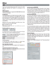
Positioning Inverter System
2 A bis 170 A (P7000)
375 W - 90 kW (P6000)
Application
manual
Antriebe mit System
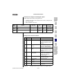
Overview of documentation
Operation Manual
P7000/P6000
With delivery
(depending on supply
package)
Application Manual
F1
D
Quick and easy initial
commissioning
Adapting the drive system to
the application
Application Manual P7000/P6000
F1
ID no.: 1005.22 B.1-00
Dated:
10/2005
Valid from software version V0.55 (P7000)
Valid from software version V1.3 (P6000)
We reserve the right to make technical changes.
Dear user
this manual mainly addresses you as a programmer for drive and
automation solutions. It describes how you can match your new drive
system optimally to the corresponding application. At this point we
assume that your drive is already running – otherwise you should first
read the operating instructions.
Don't let the sheer volume of this manual put you off: Only the chapters 1
to 3 contain basic information you should become familiar with. All other
chapters and the appendix are intended for looking up information.
(They show the full scope of functions and the flexibility of the software for
the positioning controllers to solve the most diverse drive tasks.)
Guide through this
manual
1
Safety
1
2
Device hardware
2
3
Operation structure
3
4
Encoder
4
5
Positioning controller
5
6
General software functions
6
7
User programming
7
8
Speed control "OpenLoop"
8
Appendix: Error messages and index
Application Manual P7000/P6000
A
DE
EN
FR
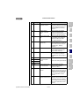
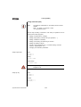
Pictograms
➢ Note: Useful information
➢ Cross-reference: Further information in other
chapters of the user manual or
additional documentations
1.
➢ Step 1: Step-by-step instructions
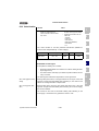
Warning symbol
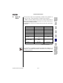
Application Manual P7000/P6000
General explanation
Danger class acc. to
ANSI Z 535
Attention! Operating errors may cause
damage to or malfunction of the drive.
This may result in
physical injury or
damage to material.
Danger, high voltage!Improper
behaviour may cause fatal accident.
Danger to life or severe
physical injury.
Danger from rotating parts!The drive
may automatically start.
Danger to life or severe
physical injury.
Contents
1
Safety
1.1
Measures for your safety ........................................1-1
1.2
Intended use ............................................................1-3
1.3
Responsibility ..........................................................1-4
2
Equipment hardware
2.1
Terminal positions P7000 .......................................2-2
2.2
Terminal positions P6000 .......................................2-7
2.3
Light emitting diodes ............................................2-11
2.4
Resetting parameter settings ...............................2-12
2.5
Loading device software .......................................2-13
2.6
Device protection ..................................................2-14
3
Application Manual P7000/P6000
Operation structure
3.1
Operation levels in the parameter structure ..........3-2
3.2
3.2.1
Operation with PROFITOOL .......................................3-4
Operation masks ..................................................3-5
3.3
Operation with KP10 operation panel .....................3-9
3.4
Commissioning ......................................................3-13
4
P7000/P6000 in rotary speed operation
4.1
Preset solutions ......................................................4-2
4.2
4.2.1
4.2.2
General functions ....................................................4-3
Torque / rotary speed profile generator ................4-3
Limitations/Stop ramps ........................................4-5
4.3
Torque control with
reference value via analog input ............................4-6
DE
EN
FR
Application Manual P7000/P6000
4.4
Speed control with
reference value via analog input ............................4-6
4.5
Speed control with
reference value from fixed speed table .................4-7
4.6
4.6.1
4.6.2
Speed control with
reference value and control via field bus .............. 4-9
CANopen ............................................................. 4-9
PROFIBUS .......................................................... 4-10
4.7
Speed control with reference value via PLC ........ 4-10
4.8
4.8.1
4.8.2
Assignment of control terminal ........................... 4-10
Terminal assignment P7000 .............................. 4-11
Terminal assignment P6000 .............................. 4-12
5
P7000/P6000 in positioning operation
5.1
Pre-set solutions .....................................................5-2
5.2
5.2.1
5.2.2
5.2.3
5.2.4
5.2.5
5.2.6
General functions .................................................... 5-4
Positioning modes ............................................... 5-5
Units and standardization .................................... 5-6
Travel profile ....................................................... 5-9
Referencing ....................................................... 5-13
Limit switch ....................................................... 5-25
Manual operation / Jog mode ............................ 5-26
5.3
5.3.1
5.3.2
5.3.3
5.3.4
5.3.5
Positioning with table travel sets ........................5-28
Travel set selection ............................................ 5-28
Sequence of travel set selection with follow-up order
logic .................................................................. 5-30
Parameterization of the travel set table .............. 5-32
Switching points ................................................ 5-37
Teach in ............................................................ 5-39
5.4
5.4.1
5.4.2
Positioning and control via field bus ...................5-40
CANopen ........................................................... 5-40
PROFIBUS .......................................................... 5-40
5.5
Positioning with PLC ............................................. 5-41
5.6
5.6.1
5.6.2
6
Application Manual P7000/P6000
Assignment of control terminal ............................5-41
Terminal assignment P7000 ..............................5-42
Terminal assignment P6000 ..............................5-43
General software functions
6.1
6.1.1
6.1.2
6.1.3
6.1.4
Inputs and outputs ..................................................6-3
Digital inputs .......................................................6-4
Digital outputs ..................................................6-13
Analog inputs .....................................................6-23
Analog output for P6000 ....................................6-29
6.2
6.2.1
6.2.2
6.2.3
6.2.4
6.2.5
6.2.6
6.2.7
Setpoint generation ...............................................6-32
Rotary speed profile ...........................................6-33
Limitations .........................................................6-34
Stop ramps ........................................................6-36
Reference encoder/Master-Slave operation ........6-39
Setpoint structure - further settings/control location ..
6-46
Control location ..................................................6-55
Motor potentiometer function .............................6-58
6.3
Motor control .........................................................6-62
6.4
6.4.1
6.4.2
6.4.3
6.4.4
Motor and transducer ...........................................6-67
Motor data .........................................................6-67
Encoder .............................................................6-74
Motor protection ................................................6-83
Motor holding brake ...........................................6-90
6.5
6.5.1
6.5.2
Bus systems ........................................................6-100
CANopen ..........................................................6-100
PROFIBUS ........................................................6-104
6.6
Cam controller .....................................................6-106
6.7
Setting KP10 ........................................................6-112
6.8
6.8.1
6.8.2
6.8.3
6.8.4
Actual values .......................................................6-117
Temperature monitoring ..................................6-117
Device data ......................................................6-118
Options ............................................................6-119
CANopen Field bus ..........................................6-122
DE
EN
FR
Application Manual P7000/P6000
6.9
6.9.1
6.9.2
Warnings/errors ..................................................6-124
Error messages ............................................... 6-124
Warning
messages ........................................................ 6-131
7
User programming
7.1
PLC functionality .....................................................7-3
7.2
7.2.1
7.2.2
7.2.3
7.2.4
7.2.5
7.2.6
PLC program ...........................................................7-4
PLC editor ............................................................ 7-4
New generation of program ................................. 7-5
PLC program structure ........................................ 7-5
Program testing and editing ................................. 7-7
PLC program files ................................................ 7-7
Program handling ................................................ 7-8
7.3
7.3.1
7.3.2
PLC command syntax ........................................... 7-10
Overview ........................................................... 7-11
Detailed
explanations ...................................................... 7-17
7.4
7.4.1
7.4.2
PLC control and parameters ................................. 7-41
PLC variables ..................................................... 7-42
PLC control parameters ..................................... 7-43
7.5
7.5.1
7.5.2
7.5.3
7.5.4
PLC program examples ........................................ 7-45
Conveyor belt .................................................... 7-46
Absolute positioning .......................................... 7-47
Relative positioning ........................................... 7-49
Sequential program ........................................... 7-50
8
Speed Control "OpenLoop" for P7000/
P6000
8.1
Preset solutions ......................................................8-2
8.2
8.2.1
8.2.2
8.2.3
General functions .................................................... 8-3
Data set changeover ............................................ 8-3
Speed profile generator "OpenLoop" ................... 8-5
Limitations/Stop ramps ........................................ 8-8
8.3
8.3.1
8.3.2
8.3.3
8.3.4
8.3.5
"OpenLoop" motor control method ......................8-10
Start current controller .......................................8-11
Vibration damping controller ..............................8-13
Current limit controller .......................................8-14
DC-holding current controller .............................8-16
v/f-characteristics curve ....................................8-17
8.4
Speed control "OpenLoop" with
0-10 V or fixed speeds ..........................................8-19
8.5
Speed control "OpenLoop" with
setpoint and control via field bus .........................8-22
A
Application Manual P7000/P6000
A.1
Overview of all error messages ............................. A-2
B
Index
DE
EN
FR
Application Manual P7000/P6000
1
1 Safety
1.1
Measures for
your safety
2
In order to avoid physical injury and/or material damage the following information must
be read before initial start-up.
The safety regulations must be strictly observed at any time.
Read the Operation Manual first!
•
Follow the safety instructions!
•
Please observe the user information
Electric drives are generally potential
danger sources:
•
Electrical voltage <230 V/460 V: Dangerously high
voltage may still be present 10 minutes after the power
is cut. You should therefore always check that the
system has been deenergized. (applies only for P7000/
P6000)
•
Rotating parts
•
Hot surfaces
For persons with pacemakers, metal containing implants
and hearing aids etc. access to the following areas is
prohibited:
−
−
Danger:
Application Manual P7000/P6000
4
5
6
7
Protection against magnetic and/or electromagnetic
fields during installation and operation.
•
3
Areas in which drive systems are installed, repaired
and operated.
Areas in which motors are assembled, repaired and
operated. Motors with permanent magnets are
sources of special dangers.
8
A
If there is a necessity to access such areas a
decision from a physician is required.
1-1
DE
EN
FR
1 Safety
Your qualification:
• In order to prevent personal injury or damage to
property, only personnel with electrical engineering
qualifications may work on the device.
• The qualified personnel must familiarise themselves with
the Operation Manual (refer to IEC364, DIN VDE0100).
• Knowledge of the national accident prevention
regulations (e. g. VBG 4 in Germany)
During installation follow these instructions:
• Always comply with the connection conditions and
technical specifications.
• Comply with the standards for electrical installations,
such as wire cross-section, earthing lead and ground
connections.
• Do not touch electronic components and contacts
(electrostatic discharge may destroy components).
Application Manual P7000/P6000
1-2
1 Safety
1.2
Intended use
Drive controllers are components for installation into stationary electric
systems or machines.
When installed in machines the commissioning of the drive controller (i. e.
start-up of intended operation) is prohibited, unless it has been
ascertained that the machine fully complies with the regulations of the
EC-directive 98/37/EC (Machine Directive); compliance with EN 60204 is
mandatory.
1
2
Commissioning (i. e. starting intended operation) is only permitted when
strictly complying with EMC-directive (89/336/EEC).
The series P7000/P6000 complies with the low voltage directive 73/23/
EEC
For the drive controller the harmonized standards of series EN 50178/
DIN VDE 0160 in connection with EN 60439-1/ VDE 0660 part 500 and
EN 60146/ VDE 0558 are applied.
The harmonized standards EN 50178/DIN VDE 0160 and EN 61800-3
are applied for the drive controllers.
If the drive controller is used in special applications, e. g. in areas subject
to explosion hazards, the applicable regulations and standards (e. g. in
Ex-environments EN 50014 “General provisions” and EN 50018
“Flameproof housing”) must be strictly observed.
Repairs must only be carried out by authorized repair workshops.
Unauthorised opening and incorrect intervention could lead to physical
injury or material damage. The warranty granted by LUST will become
void.
Note:
The use of drive controllers in mobile equipment is assumed
an exceptional environmental condition and is only permitted
after a special agreement.
3
4
5
6
7
8
A
Application Manual P7000/P6000
1-3
DE
EN
FR
1 Safety
1.3
Responsibility
Electronic devices are never fail-safe. The company setting up and/or
operating the machine or plant is itself responsible for ensuring that the
drive is rendered safe if the device fails.
EN 60204-1/DIN VDE 0113 "Safety of machines", in the section on
"Electrical equipment of machines", stipulates safety requirements for
electrical controls. They are intended to protect personnel and machinery,
and to maintain the function capability of the machine or plant concerned,
and must be observed.
An emergency stop system does not necessarily have to cut the power
supply to the drive. To protect against danger, it may be more beneficial to
keep individual drives running or to initiate specific safety sequences.
Execution of the emergency stop measure is assessed by means of a risk
analysis of the machine or plant, including the electrical equipment in
accordance with DIN EN 1050, and is determined by selecting the circuit
category in accordance with DIN EN 954-1 "Safety of machines - Safetyrelated parts of controls".
Application Manual P7000/P6000
1-4
1
2 Equipment hardware
2
3
2.1
Terminal positions P7000 .......................................2-2
2.2
Terminal positions P6000 .......................................2-7
2.3
Light emitting diodes ............................................2-11
2.4
Resetting parameter settings ...............................2-12
2.5
Loading device software .......................................2-13
2.6
Device protection ..................................................2-14
4
5
6
Info: This chapter shows general items concerning the equipment
hardware, which are required to understand and work with the
application manual. Further information on equipment hardware
can be found in the corresponding operating instructions for the
positioning controllers.
7
8
A
Application Manual P7000/P6000
2-1
DE
EN
FR
2 Equipment hardware
2.1
Terminal
positions P7000
X7
X6
X6
ERR/WARN
READY
POWER
X5
Typ
:
Net
z:
Ausg
.:
S1
S2
SN
.:
000
.0
IK
CHN
STE
RIEB nau
ANT 3 Lah
X1
3
00.0
D-3563
000
000
0
REL
X2
REL
24
ISDS
H
ISD0
6
ISD0
5
ISD0
4
ISD0
3
ISD0
2
ISD0
1
ISD0
0
+24V
23
DGND
14
22
21
20
19
18
17
16
15
HH44
HH55
12
11
10
9
8
7
6
5
4
3
2
1
RSH
RSH
ENPO
OSD0
2
OSD0
1
OSD0
0
ISA1
ISA1
+
ISA0
ISA0
+
+24V
Typ:
1
1
2
2
X1
X0
Typ:
Netz: Netz:
.:
Ausg sg.:
10
Au
00
SN.: 0.0000.: 00 0000
SN 00
000.00 0.000.00
00
X1
1
DGND
X9
S1
X3
X1
1
X1
2
EF
89
67
01
2345
ABCD
Ac
h
Ko n
tu
ladendensa ng
Betrizeit tore :
ebsa> 3 ntnl Min
beaceitung.
hten
!
WA
Capa R
tim cito NIN
Paye > 3r disc G
operattentmin. harge
atio ion
n m to th
anua e
l!
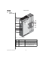
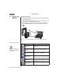
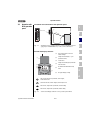
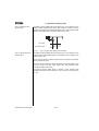
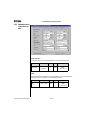
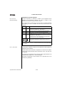
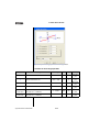
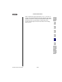
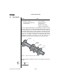
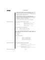
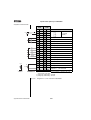
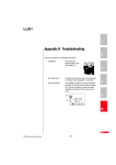
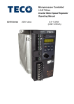
Fig. 2.1
No.
View of device P7000
Designation
H1, H2, H3 Light emitting diodes
Equipment status display
S1
Encoder switch
Setting the CAN-address =
hardware address + parameter value COADR
X1
Power terminal
Mains, motor, DC supply (L+/L-)
up to < 22 kW: Braking resistor L+/RB,
from > 22 kW: Braking resistor L+/RB
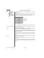
Table 2.1
Application Manual P7000/P6000
Function
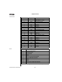
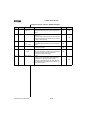
Legend to "View of device P7000"
2-2
2 Equipment hardware
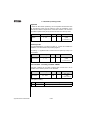
No.
Designation
Function
X2
Control terminal
8 digital inputs, 2 analog inputs, (10 bit)
3 digital outputs, 1 relay
Safe stop with relay output
X3
Motor temperature
monitoring
PTC, following DIN 44082 or
KTY 84-130 (linear temperature sensor) or
Klixon (thermal circuit breaker)
X4
RS232 port
for PC with PROFITOOL or control unit KP10
X5
CAN-interface
CANopen - interface DSP402
X6
Resolver connection
Resolver
X7
TTL-/SSI encoder
interface
TTL encoder
SSI absolute value transducer, optionally: Sin-Cos
transducer
X8
Optional board slot
Expansion board slot for e.g. optional module
ULZ_DPV1 (PROFIBUS-DP)
X9
Brake driver
2A max.
X10
Voltage supply for
optional module
+ 24 V, ground
X11
Interface
PROFIBUS-DP
Input bus connection
X13
Address coding plug
Only with optional module DPV1
Address encoder switch
Only with optional module DPV1
S1, S2
Table 2.1
1
2
3
4
5
6
7
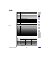
Legend to "View of device P7000"
Power terminal
X1
Table 2.2
Application Manual P7000/P6000
Designation
X1
Designation
Motor cable U
Motor cable U
Motor cable V
Motor cable V
Motor cable W
Motor cable W
PE-conductor
PE-conductor
PE-conductor
PE-conductor
D.C. ling voltage +
D.C. ling voltage +
Braking resistor
Braking resistor
D.C. ling voltage -
D.C. ling voltage -
PE-conductor
PE-conductor
NC
Mains phase L3
Neutral conductor
Mains phase L2
Mains phase
Mains phase L1
Power terminal designation P7000S and P7000T
2-3
8
A
DE
EN
FR
2 Equipment hardware
Control terminal
X2
Designation
1
DGND
digital ground
2
+24V
Auxiliary voltage UV = 24 V DC
3
ISAO+
Analog input 10 bit ± 10 V
4
ISAO-
Analog input
5
ISA1+
Analog input 10 bit ± 10 V
6
ISA1-
Analog input
7
OSD00
Digital output
8
OSD01
Digital output
9
OSD02
Digital output
10
ENPO
Power stage hardware enable
11
RSH
Relay output safe stop
12
RSH
Relay output safe stop
13
DGND
digital ground
14
+24V
Auxiliary voltage UV = 24 V DC
15
ISD00
Digital input 0
16
ISD01
Digital input 1
17
ISD02
Digital input 2
18
ISD03
Digital input 3
19
ISD04
Digital input 4
20
ISD05
Digital input 5
21
ISD06
Digital input 6
22
ISDSH
Digital input safe stop
23
REL
Relay output
24
REL
Relay output
Table 2.3
RS232
Signal assignment for control terminal X2, P7000
Pin-No.
Function
1
+15 V DC for control unit KP10
2
TxD, data transmission
3
RxD, data reception
4
not used
5
GND for +15 V DC of the control unit KP10
6
+24 V DC, voltage supply control print
7
not used
8
not used
9
GND for +24 V DC, voltage supply control print
Table 2.4
Application Manual P7000/P6000
Function
Pin assignment of the serial interface X4, 9-pin D-Sub socket
2-4
2 Equipment hardware
CAN
Pin-No.
Function
1
Wave terminating resistor 120 Ω internal for CAN by means of jumper
between Pin 1 and Pin 2
2
CAN_LOW, CAN signal
3
CAN_GND, reference ground of CAN 24 V (Pin 9)
4
CAN-SYNC_LOW.
5
Wave terminating resistor 120 Ω internal for CAN-SYNC by means of
jumper between Pin 5 and Pin 4
6
CAN_GND, bridged with Pin 3
7
CAN_HIGH, CAN signal
8
CAN-SYNC_HIGH.
9
CAN_+24 V (24 V ± 10%, 50 mA).
This supply voltage is required for CAN operation.
Table 2.5
Resolver
2
Function
1
Sine+, S2
2
Sine-, S4
3
Cosine+, S1
4
+5V
5
PTC+, motor temperature monitoring
6
REF+, resolver excitation R2
7
REF-, excitation-, R1
8
Cosine-, S3
9
PTC-
Table 2.6
3
4
Pin assignment of CAN-interface X5, 9-pin D-Sub pin
Pin-No.
1
5
6
7
8
Pin assignment of resolver interface X6, 9-pin D-Sub, socket
A
Encoder
Function
Pin-No.
SSI
Hiperface
1
A-
A-
REFCOS
2
A+
A+
+COS
DATA+
Data +, RS485
3
+5V ± 5% at 150mA
4
DATA+
Table 2.7
Application Manual P7000/P6000
Sine/Cosine
(optional)
Pin assignment for encoder interface X7, 15-pin D-Sub High
Density, socket
2-5
DE
EN
FR
2 Equipment hardware
Function
Pin-No.
Sine/Cosine
(optional)
SSI
Hiperface
5
DATA-
DATA-
Data -, RS485
6
B-
B-
REFSIN
GND
GND
GND
B+
+SIN
7
8
9
R-
10
R+
11
B+
12
Sense +
13
Sense +
14
CLK+
CLK+
15
CLK-
CLK-
Table 2.7
Application Manual P7000/P6000
Pin assignment for encoder interface X7, 15-pin D-Sub High
Density, socket
2-6
2 Equipment hardware
2.2
Terminal
positions P6000
1
2
X7
F0
9A
78
12
3456
BCDE
S3
3
ERR/WARN
READY
POWER
X5
Typ
:
Net
z:
Ausg
.:
S1
S2
SN
.:
000
.0
IK
CHN
STE
RIEB nau
ANT 3 Lah
X1
3
00.0
D-3563
000
000
0
HH44
HH55
Typ:
1
1
2
2
X1
X0
4
Typ:
Netz: Netz:
10
.:
Ausg
.:
Ausg
00
SN.: 0.0000.: 00 0000
SN 0.0000
000.00
000.00
X1
1
5
X1
1
X1
2
6
7
A
Ko
ladendensa
Betrizeit tore
ebsa> 3 ntnl Min
beaceitung.
hten
!
8
WA
Capa R
tim cito NIN
Paye > 3r disc G
operattentmin. harge
atio ion
n m to th
anua e
l!
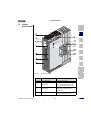
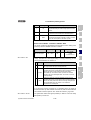
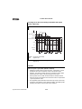
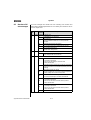
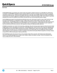
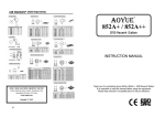
Fig. 2.2
Position plan P6000
A
No.
Designation
Function
H1, H2, H3 Light emitting diodes
X1
Power terminal
Mains, motor, DC supply (L+/L-)
up to < 22 kW: Braking resistor L+/RB,
from > 22 kW: Braking resistor L+/RB
X2
Control terminal
4 digital inputs, 2 analog inputs
3 digital outputs, (of these 1 relay)
1 analog output
X3
PTC-terminal
PTC, thermal circuit breaker or linear
temperature sensor KTY 84-130
Table 2.8
Application Manual P7000/P6000
Equipment status display
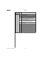
Legend to "Position plan P6000"
2-7
DE
EN
FR
2 Equipment hardware
No.
Designation
Function
X4
RS232 port
for PC with PROFITOOL or control unit KP10
X5
CAN-interface
Access to integrated CAN-interface
X7
TTL-/SSI encoder interface
for connection of suitable encoders
S3
Address encoder switch
CANopen
Setting the CAN-address =
hardware address + parameter value
COADR
X8
Optional board slot
e.g. optional module DPV1
X10
Voltage supply for
optional module
+ 24 V, ground
X11
PROFIBUS-DP interface
Input bus connection
X13
Address encoder plug
Only with optional module DPV1
Address encoder switch
Only with optional module DPV1
S1, S2
Table 2.8
Legend to "Position plan P6000"
Power terminal
X1
Table 2.9
Application Manual P7000/P6000
Designation
X1
Designation
Motor cable U
Motor cable U
Motor cable V
Motor cable V
Motor cable W
Motor cable W
PE-conductor
PE-conductor
PE-conductor
PE-conductor
D.C. ling voltage +
D.C. ling voltage +
Braking resistor
Braking resistor
D.C. ling voltage -
D.C. ling voltage -
PE-conductor
PE-conductor
NC
Mains phase L3
Neutral conductor
Mains phase L2
Mains phase
Mains phase L1
Power terminal designation P6000S and P6000T
2-8
2 Equipment hardware
Control terminal
X2
Designation
20
OSD02/20
Make contact of two-way relay
19
OSD02/19
Root of two-way relay
18
OSD02/18
Break contact of two-way relay
17
DGND
digital ground
16
OSD01
digital output
15
OSD00
digital output
14
DGND
digital ground
13
UV
12
ISD03
digital input
11
ISD02
digital input
10
ISD01
digital input
9
ISD00
digital input
8
ENPO
7
UV
6
UV
5
OSA00
analog output
4
AGND
analog ground
3
ISA01
analog input
2
ISA00
analog input
1
UR
Table 2.10
RS232
X2-18
X2-19
1
X2-20
Auxiliary voltage 24 V
2
3
4
Power stage hardware enable
Auxiliary voltage 24 V DC
Auxiliary voltage 24 V DC
5
6
Reference voltage +10,5 V
Control terminal designation P6000
Pin-No.
7
Function
1
+15 V DC for control unit KP10
2
TxD, data transmission
3
RxD, data reception
4
not used
5
GND for +15 V DC of the control unit KP10
6
+24 V DC, voltage supply control print
7
not used
8
not used
9
GND for +24V DC, voltage supply control print
Table 2.11
Application Manual P7000/P6000
Function
8
A
Pin assignment of the serial interface X4, 9-pin D-Sub socket
2-9
DE
EN
FR
2 Equipment hardware
CAN
Pin-No.
Function
1
Wave terminating resistor 120 Ω internal for CAN by means of jumper
between Pin 1 and Pin 2
2
CAN_LOW, CAN signal
3
CAN_GND, reference ground of CAN 24 V (Pin 9)
4
not used, please do not connect
5
not used, please do not connect
6
CAN_GND, bridged with Pin 3
7
CAN_HIGH, CAN signal
8
not used, please do not connect
9
CAN_+24 V (24 V ± 25%, 50 mA).
This supply voltage is required for CAN operation.
Table 2.12
Pin assignment of CAN-interface X5, 9-pin D-Sub pin
Encoder
Pin-No.
Function SSI
1
A-
DATA-
2
A+
DATA+
3
+5 V / 150 mA
+5 V / 150 mA
4
not used, please do not connect
5
not used, please do not connect
6
B-
7
not used, please do not connect
8
GND
CLK-
GND
9
R-
10
R+
11
B+
CLK+
12
+5 V (sensor)
+5 V (sensor)
13
GND (Sensor)
GND (Sensor)
14/15
Table 2.13
Application Manual P7000/P6000
Function TTL
Wave terminating resistor 120 Ω internal for track B
by means of jumper between Pin 14 and Pin 15
Pin assignment for encoder terminal X7, 15-pin D-Sub High
Density, socket
2-10
2 Equipment hardware
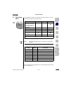
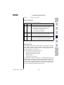
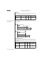
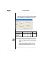
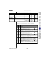
2.3
Light emitting
diodes
P7000/
P6000
H1 H2 H3
The positioning controller is fitted with three status LED’s in red (H1),
yellow (H2) and green (H3) at the top right.
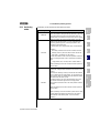
Device status
red LED (H1)
yellow LED (H2)
green LED (H3)
Supply voltage 24 V DC (internal
or external) for control element
applied or closed loop control in
"Parameterization" status
❍
❍
●
Ready (ENPO set)
❍
●
●
In service/auto-tuning active
❍
✳
●
Warning (at Standby)
❍
●
●
Warning (active with operation/
self-adjustment)
❍
✳
●
✳ (flash code)
❍
●
Error
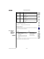
❍ LED off, ● LED on, ✳ LED flashing
Table 2.14
Note:
1
2
3
4
5
Meaning of the light emitting diodes
The parameterization mode by control unit is not separately
indicated.
6
7
Flash code of
red LED
Display
control unit
Cause of fault
1x
E-CPU
Collective error message
2x
E-OFF
Undervoltage cut-off
3x
E-OC
Overcurrent cut-off
4x
E-OV
Overvoltage cut-off
5x
E-OLM
Motor overloaded
6x
E-OLI
Device overloaded
7x
E-OTM
Motor temperature too high
8x
E-OTI
Cooling temperature too high
Table 2.15
8
A
Error messages
Error messages can be displayed more accurately with the KP10 control
unit or the PROFITOOL.
Application Manual P7000/P6000
2-11
DE
EN
FR
2 Equipment hardware
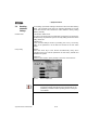
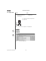
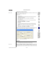
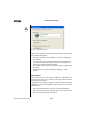
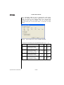
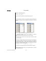
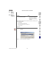
2.4
Resetting
parameter
settings
Parameter reset
The resetting of parameter settings is divided into two areas with differing
effects. The parameter reset returns an individual parameter to the last
saved value. Device reset restores the entire dataset to factory setting
(delivery defaults).
In the KEYPAD PARA menu:
If you are in the setup mode of a parameter and press the two arrow keys
simultaneously, the parameter you are currently editing will be reset to the
setting saved last.
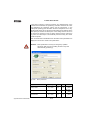
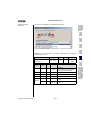
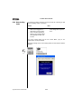
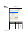
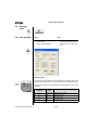
In PROFITOOL:
In the focussed settings window by actuating the F1-key. The factory
setting of the parameter is to be taken and entered in the tab "Value
Range".
Factory setting
KEYPAD:
Press both arrow keys of the KEYPAD simultaneously during servo
controller power-up to reset all parameters to their factory defaults and
reinitialise the system
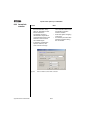
PROFITOOL:
Select function "Reset to factory default" in the menu "Active device".
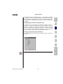
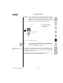
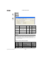
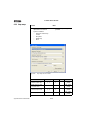
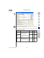
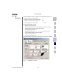
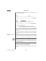
Fig. 2.3
Note:
Application Manual P7000/P6000
Reset in PROFITOOL
This factory setting also resets the selected default solution.
Check the terminal assignment and the functionality of the
positioning controller in these operating modes or load your
user dataset.
2-12
2 Equipment hardware
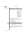
2.5
Loading device
software
With the PROFITOOL you can load a new device software (Firmware) into
the Flash-EPROM of the devices. This enables updating of the software
without having to open the positioning controllers.
1
1. For this purpose set up a connection between PROFITOOL and
positioning controllers.
2. From the menu "Options" choose the option "Load device software
(Firmware) ...“. From here the PROFITOOL will guide you through the
other work steps. LEDs H2 and H3 will light during transfer of the
Firmware. After successful transfer the LED H2 will go out, if no
ENPO signal is applied.
2
3
4
5
6
7
8
A
Application Manual P7000/P6000
2-13
DE
EN
FR
2 Equipment hardware
2.6
Device
protection
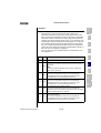
Function
Effect
• Protection of the positioning
controller against damage
caused by overload.
The positioning controller stops
the motor with an error message.
•
E-OTI, if the device
temperature exceeds a fixed
limit
•
E-OLI, if the integrated
current time value exceeds
the limit value set in
dependence on the power
module by a certain
triggering time
•
E-OC when detecting short
circuit or earth fault
•
The positioning controller
can submit a warning when
the I2xt-device protection
integrator is started
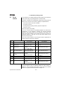
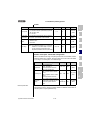
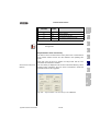
The software and hardware of the positioning controller automatically
takes over the monitoring and protection of the device.
The power stage protects itself against overheating in dependence on
• the heat sink temperature,
• the applied d.c. link voltage,
• the transistor modules used in the power stages and
• the modulation switching frequency
Note:
The current heat sink temperature of the positioning
controller in the area of the power transistors (KTEMP) and
the internal device temperature (DTEMP) are displayed in °C
(see chapter 6.8.2).
Under high loads the I2xt-integrator is activated. The I2xt monitoring
serves the purpose of protecting the device against permanent overloads.
The switch-off limit is calculated on the basis of rated current and the
overload ability of the controller.
Application Manual P7000/P6000
2-14
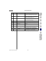
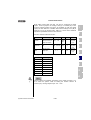
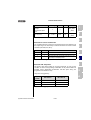
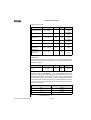
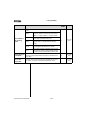
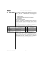
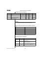
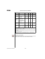
2 Equipment hardware
Device
Switch-off limit I²xt device
P6000-0007SAC1 (O,375 kW)
to P6000-0150TEW1 (15 kW)
P7000-0024SAC1 (2,4 A)
to P7000-0320TEW1 (32 A)
1,8 x Rated device current for 30 s
P6000-0220TFW1 (22 kW)
to P6000-0900THW1 (90 kW)
1,5 x Rated device current for 60 s
P7000-0450TFW1 (45 A)
to P7000-1700THW1 (170 A)
2,0 x Rated device current for 3 s
Table 2.16
2
3
Switch-off limits I²xt acc. to device size
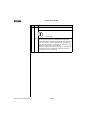
I2xt
With active
integrator the warning message can be submitted to a
digital output, field bus or PLC.
Short circuit
1
The hardware of the positioning controller will detect a short circuit at the
motor output and switch off the motor.
4
5
Info: Detailed information on permissible current load for the positioning
controllers can be taken from the operating instructions.
6
7
8
A
Application Manual P7000/P6000
2-15
DE
EN
FR
2 Equipment hardware
Application Manual P7000/P6000
2-16
1
3
Operation structure
2
3
3.1
Operation levels in the parameter structure ..........3-2
3.2
3.2.1
Operation with PROFITOOL .......................................3-4
Operation masks ..................................................3-5
3.3
Operation with KP10 operation panel .....................3-9
3.4
Commissioning ......................................................3-13
Due to the use of different operation variants and extensive possibilities
for parameterization the operation structure is very flexible. The well
organized data structure thus supports the handling of data and the
parameterization of the positioning controllers.
Parameterization of the positioning controllers may take place via the
easy to use hand-held KP10 operation panel or the comfortable PC user
interface PROFITOOL.
4
5
6
7
8
A
Application Manual P7000/P6000
3-1
DE
EN
FR
3 Operation structure
3.1
Operation levels
in the
parameter
structure
With adjustable parameters the positioning controllers can be adapted to
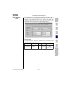
any application. For the internal values of the positioning controllers there
are further parameters available, which are password protected for
reasons of operating safety.
The operation levels are adjusted by means of parameters. The number
of editable and displayable parameters changes in dependence on the
operation level. The higher the operation level, the higher the number of
parameters with access rights. In contrast, the clarity of the parameters
actually needed by the user to reach his application as quickly as
possible, is reduced. This means that operation is remarkably easier
when choosing the lowest possible operation level.
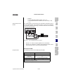
Note:
The operation levels protect against unauthorized access.
Thus the operation level 01-MODE = 2 is activated about 10
minutes after last activation of the button when using the
KP10 operation panel.
Changing the operation level
If a higher operation level is selected via parameter 01-MODE, the
associated password is automatically requested. This password can be
changed by means of a password editor (setting "000" = password
disabled).
Target group
Password
parameter
Layman
no parameter
available
Beginner
362-PSW2
Comment
without access right, only for status monitoring
• no parameterization, display of basic parameters
Operation
level 01MODE
Password in
1
-
2
000
3
000
4
000
WE 1)
with basic knowledge for minimum operation
• extended basic parameters editable
• extended parameter display
for commissioning and field bus connection
Advanced
363-PSW3
• Parameterization for standard applications
• extended parameter display
with expert knowledge in control technology
Expert
364-PSW4
• all closed loop control parameters editable
• extended parameter display
Others
365-PSW5
for system integrators
Expert personnel
367-PSWCT
Operation and start-up using the KP10 operation panel
1)
WE = Factory setting
Table 3.1
Application Manual P7000/P6000
Setting operation levels
3-2
5
-
CTRL menu
573
3 Operation structure
If a password is set up for operation level 2 ... 4, both viewing and editing
of parameters in the corresponding operation level by means of the KP10
operation panel is maintained, until a change to a lower operation level.
For this purpose a new operation level must be selected via parameter
01-MODE.
Changing the password for an operation level
A password can only be changed via levels with operation rights, i.e.
passwords of a higher operation level cannot be changed or viewed. A
password is changed by selecting the parameter, editing and finally
saving the password by pressing the Enter-key on the KP10 operation
panel. This change can also be made via PROFITOOL. The password will
only become active when changing to a lower operation level.
Changing the operation level in PROFITOOL
1
2
3
4
The corresponding level is selected in menu option "Extras - Select new
user level".
5
6
7
8
Changing levels does not require a password.
Application Manual P7000/P6000
3-3
A
DE
EN
FR
3 Operation structure
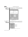
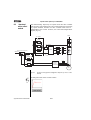
3.2
Operation with
PROFITOOL
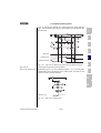
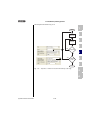
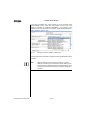
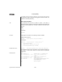
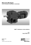
Connection and start
• Connect the interface cable and switch on the power supply for the
positioning controller.
• After the program start the PROFITOOL will automatically set up a link
to the connected controller (minimum V2.3).
• If the automatic connection does not work, check the setting in the
menu Extras > Options and set up the connection with the Icon
.
X7
X6
X5
ANTRIEBST
RS232
D-35633
ECHNIK
ERR/WARN
READY
POWER
Lahnau
Typ:
Netz:
Ausg
.:
SN.:
000
.000
.000
000
H4
H5
RS232
3m m
ax
00
1
2
X10
X11
.
Ω
D RIV E
M AN AG ER
X12
ACH
TUN
Konden
ladeze satorenG
Betriebit >
t3 Min.
sanleit
beachtung
en!
WAR
Capaci NIN
time tor
dischaG
Pay > 3 min.
rge
attentio
operat
ion n to
manuathe
l!
CDB/CDE
CDF
Fig. 3.1
Connection via RS232 interface cable (9-pin, socket/pins)
The most important functions
Icon
Function
Connect to the
device
Further information can
be found in the help to the
PROFITOOL.
Menu
Communication > Connect > Single
device
Changing the device
Active device > Change settings
settings
Print parameter data
Active device > Print settings
set
Control drive
Active device > Control > Basic
operation modes, no position setpoints
Digital Scope
Active device > Monitor > Quickly
changing digital scope values
Saving settings from Active device > Save settings of device
device to file
to
Application Manual P7000/P6000
3-4
3 Operation structure
Icon
Function
Load settings from
file into device
Active device > Load settings into
device from
Bus initialization
(change settings)
Communication > Bus configuration
Disconnect the link to
the device
Compare device
settings
Note:
Menu
1
2
Communication > Disconnect
3
Active device> Compare settings
4
Further information can be found in the operating instructions
for the PROFITOOL.
5
6
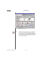
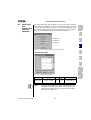
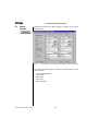
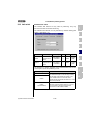
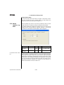
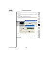
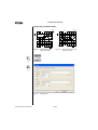
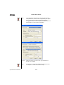
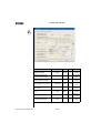
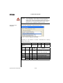
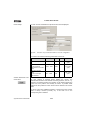
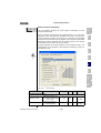
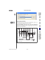
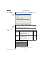
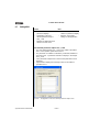
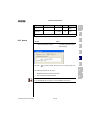
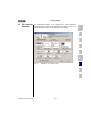
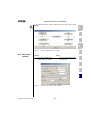
3.2.1 Operation
masks
VIA ICON "CHANGE
DEVICE SETTINGS" or via
menu:
Active device > Change
settings
7
8
A
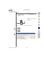
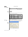
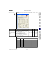
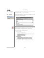
Fig. 3.2
Adjustment in minimized view
This operation mask "Settings" can be used to parameterize the position
controllers.
Application Manual P7000/P6000
3-5
DE
EN
FR
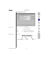
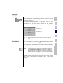
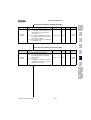
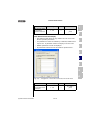
3 Operation structure
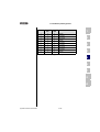
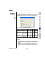
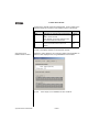
Fig. 3.3
Note:
Application Manual P7000/P6000
Adjustment in extended view
Parameter changes only take place in the volatile random
access memory and must subsequently be saved in the
device by pressing the button "Save device settings". The
same is achieved by simultaneous pressing of both arrow
keys on the KP10 operation panel for approx. 2 seconds in
menu level (see chapter 3.3).
3-6
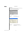
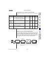
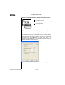
3 Operation structure
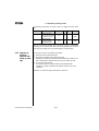
Example Operation via mask
1
2
3
4
5
Fig. 3.4
Example for operation via mask
Function of buttons
OK
Cancel
Accept
Options
Explanation of setting
→
→
→
→
Accept changes and close mask
6
Cancel changes and close mask
Accept changes (activate) and keep mask open.
Optional settings for the corresponding function
for example:
7
8
OFF (1) = no function
A
Function (max. five digits),
Display in operation panel KP200-XL
Application Manual P7000/P6000
Setting via
field bus
3-7
Plain text display
of function
DE
EN
FR
3 Operation structure
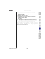
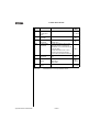
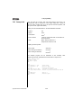
Help function:
In any input window key F1 can be used to call up a help function with
further information on the corresponding parameter.
e.g. the mask "Function selector analog standard input
Fig. 3.5
Parameter number:
Number of parameter
Abbreviation:
Name, max. five digits (display in KP10
Fig. 3.6
Application Manual P7000/P6000
Identification
Value range
Minimum/Maximum:
Value range (here: between OFF and /E-EX).
Factory setting:
After a device reset to factory setting (WE) this value is
automatically entered.
3-8
3 Operation structure
3.3
Operation with
KP10 operation
panel
Installation and connection of the operation panel
1
KP-200-XL
stop
return
X4
KP10
start
enter
3m m
ax.
b)
ACHTUNG
WARNING
Kondensatorentladezeit > 3 Min.
Betriebsanleitung
beachten!
Capacitor discharge
time > 3 min.
Pay attention to the
operation manual!
2
3
a)
Fig. 3.7
Installation of the operation panel: a) on the positioning controller
(plug X4) for P7000/P6000 or b) on the control cabinet door
Control and display elements
(1)
(2)
(1)
Chip card DATACARD to save and
transfer settings
(2)
3-digit numerical display, e. g. for
parameter number,
(3)
current menu
(4)
5-digit numerical display for parameter
name and value
(5)
Acceleration and deceleration ramp
active
(5)
(3)
(4)
VAL
Hz
start
start
enter
enter
5
6
7
8
(6)
stop
stop
return
return
4
(6)
Bar graph display, 10-digit
A
start
enter
Call up menu branches or parameters; save changes;
Control start in drive
stop
return
Quit menu branches; Cancel changes; Control stop in drive
Select menu, subject area or parameter; Increase setting
Select menu, subject area or parameter; Reduce setting
Fig. 3.8
Application Manual P7000/P6000
Control and display elements of the operation panel KP10
3-9
DE
EN
FR
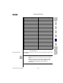
3 Operation structure
The KP10 operation panel has a menu structure for clearly arranged
operation
Menu structure
VAL
CTRL
PARA
Actual values
Subject area
• select
• select
• show
Parameters
Drive
CARD
DATACARD
• read
• control
• write
• Write
protection
• select
Capacity indicator
• change
Initial
commissioning
Fig. 3.9
Menu functions
In the menu level (display "MENU") one can use the arrow keys to change
between menus. The Start/Enter-key opens a menu, the Stop/Returnkey closes the menu.
PARA
VAL
start
enter
start
enter
stop
return
stop
return
Fig. 3.10
Note:
Application Manual P7000/P6000
CARD
CTRL
start
enter
stop
return
start
enter
stop
return
Navigating through the menu level
Parameter changes in the menu branch "PARA" only take
place in the volatile random access memory and must
subsequently be permanently saved to the read-only
memory. In menu level this can be simply accomplished by
simultaneous pressing of both arrow keys for approx. 2
seconds.
3-10
3 Operation structure
PARA
VAL
VAL
CTRL
PARA
CARD
CTRL
CARD
A
VAL
PARA
CTRL
CARD
star
t
enter
stop
retur
n
stop
retur
n
B
star
t
enter
star
t
enter
star
t
enter
VAL
PARA
CTRL
%VA
hmin
min-1
Hz/s
CARD
VAL
PARA
CTRL
CARD
1
2
CARD
%VA
hmin-1
Hz/s
3
A
1
star
t
enter
stop
retur
n
CTRL
0...9
VAL
CARD
PARA
CTRL
C1
CARD
VAL
PARA
CTRL
VAL
CARD
PARA
CTRL
CARD
%VA
hmin-1
Hz/s
%VA
hmin-1
Hz/s
stop
retur
n
stop
retur
n
PARA
CTRL
for field
parameters only
5
CARD
PARA
CTRL
CARD
star
t
enter
stop
retur
n
VAL
PARA
CTRL
VAL
CARD
PARA
star
t
enter
star
t
enter
star
t
enter
stop
retur
n
D
4
star
t
enter
star
t
enter
C2
stop
retur
n
stop
retur
n
stop
retur
n
VAL
star
t
enter
star
t
enter
stop
retur
n
stop
retur
n
CTRL
CARD
0...9
VAL
PARA
CTRL
CARD
CARD
%VA
hmin-1
Hz/s
%VA
6
7
star
t
enter
MP
A
Select menu VAL
(show actual values)
Select menu PARA
(parameterizing)
Select menu CTRL
(control drive)
Select menu CARD (load/save
with DATACARD)
B
Show permanent actual
value, use arrow key to
change to ...
Select the expert field
Drive has stopped
(if necessary password
dialog with display PASSW,
factory setting = no
password)
READ = load from DC, selection
of individual datasets possible
WRITE = save all datasets to DC
LOCK = + write protection
UNLOCK = - write protection
Select parameter
Select parameter index
Enter setpoint
Select partial parameter area
Show parameter value and
change if necessary
Start drive with Start/Enter, Function completed without
change setpoint with arrow fault
keys (MP = motor
potentiometer function)
C1 next actual value
C2 Select parameter index
D
Show actual value
Table 3.2
Application Manual P7000/P6000
8
A
Menu structure of the KP10 operation panel at a glance
3-11
DE
EN
FR
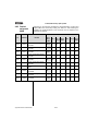
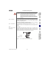
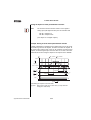
3 Operation structure
Value display in exponential
representation
The representation of the five-digit numerical display for parameter values
uses the exponential notation. The setpoint specification in the CTRLmenu is likewise specified and displayed using the exponential notation.
exponent
VAL
PARA
CTRL
CARD
base value
Fig. 3.11
exponential
value
Hz
Exponential representation in the KP10 display
The exponential representation makes work easier when considering the
exponential value a "Decimal point displacement factor".
Exponential value
Decimal point displacement direction in base value
positive
to the right ⇒value increases
negative
to the left ⇒value decreases
Table 3.3
Exponential value as "Decimal point displacement factor“
In the base value the decimal point is displaced by the number of digits
corresponding with the exponential value.
Example:
VAL
PARA
CTRL
CARD
Hz
VAL
PARA
CTRL
CARD
Hz
DATACARDS
⇒57.63 *10-1 Hz = 5.763 Hz
Decimal point displacement by two digits to the
right
⇒57.63*102 Hz = 5763 Hz
DATACARDS are created in dependence on the firmware of the positioning
controllers. In case of a firmware extension within the scope of a new
device software version the extensions are automatically written to the
DATACARD when saving ("WRITE"). DATACARDs are thus always upward
compatible.
Note:
Application Manual P7000/P6000
Decimal point displacement by one digit to the left
DATACARDS can only be read by the positioning controller
type (e.g. P6000) they have been written by.
3-12
3 Operation structure
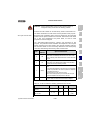
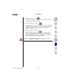
3.4
Commissioning
Commissioning procedure by following the user manual
1.
1
Initial commissioning by following the operating
instructions:
Prerequisite is the general initial
commissioning by following the operating
instructions.
The user manual solely deals with the
adaptation of the software functions.
2
If the settings made during initial commissioning by following the
operating instructions are not sufficient for the application:
2.
Selecting the optimal pre-set solution
4
The pre-set solutions cover the typical
applications for the positioning controllers.
The dataset most appropriate
application is selected.
3.
for
the
Individual adaptation of the preset solution to the
application.
The pre-set solution serves as initial point for
an application related adaptation. Further
function related adaptations are made to the
parameters in the function oriented subject
areas. Safe your settings in the unit!
4.
Check the settings of the application solution
With respect to the safety of man and machine
the application solution should only be checked
at low rotary speeds. The correct sense of
rotation must be assured. In events of
emergency can be stopped by disconnecting
the ENPO-signal and thus blocking the
controller output stage.
5.
3
5
6
7
8
A
Completion of commissioning
After successful commissioning save your
settings (with DATACARD or PROFITOOL) and
memorize the data set in the unit.
Application Manual P7000/P6000
3-13
DE
EN
FR
3 Operation structure
Application Manual P7000/P6000
3-14
1
4 P7000/P6000 in rotary speed
operation
Application Manual P7000/P6000
2
3
4.1
Preset solutions ......................................................4-2
4
4.2
4.2.1
4.2.2
General functions ....................................................4-3
Torque / rotary speed profile generator ................4-3
Limitations/Stop ramps ........................................4-5
5
4.3
Torque control with
reference value via analog input ............................4-6
4.4
Speed control with
reference value via analog input ............................4-6
4.5
Speed control with
reference value from fixed speed table .................4-7
7
4.6
4.6.1
4.6.2
Speed control with
reference value and control via field bus ..............4-9
CANopen ..............................................................4-9
PROFIBUS ..........................................................4-10
8
4.7
Speed control with reference value via PLC ........4-10
A
4.8
4.8.1
4.8.2
Assignment of control terminal ............................4-10
Terminal assignment P7000 ..............................4-11
Terminal assignment P6000 ..............................4-12
4-1
6
DE
EN
FR
4 P7000/P6000 in rotary speed operation
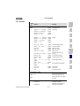
4.1
Preset solutions
Pre-set solutions are complete parameter datasets which are provided to
handle a wide variety of typical application movement tasks. The
positioning controllers are automatically configured by setting a preset
solution. The parameters for
•
•
•
•
the control location of the positioning controller,
the reference source,
the assignment of signal processing input and outputs and
the type of control
are the focal points of the setting.
The use of a pre-set solution considerably simplifies and shortens the
commissioning of the positioning controller. By changing individual
parameters, the preset solutions can be adapted to the needs of the
specific task.
A total of eleven preset solutions covers the typical areas of application
for torque/speed control with the closed-loop controllers.
Abbrevia
tion
Control location/
Reference source
Bus control profile
Chapt
.
Additionally required
documentation
TCT_1
±10V analog torque
I/O-terminals
4.8.2
SCT_1
+/-10V-analog
I/O-terminals
4.8.2
SCT_2
Fixed speed table
I/O-terminals
4.5
SCC_2
Fixed speed table
CANopen field bus interface
4.5
CANopen data transfer protocol
SCB_2
Fixed speed table
4.5
PROFIBUS data transfer protocol
SCC_3
CANopen field bus
interface
4.6
CANopen data transfer protocol
SCB_3
Field bus communication Field bus module ULZ-DPV1
- EasyDrive-Profile "Basic"
module (PROFIBUS)
4.6
PROFIBUS data transfer protocol
SCP_3
PLC
PLC
4.7
see chapter 7
SCT_4
PLC
I/O-terminals
4.7
see chapter 7
SCC_4
PLC
CANopen field bus interface
4.7
CANopen data transfer protocol
SCB_4
PLC
4.7
PROFIBUS data transfer protocol
- EasyDrive-Profile "Basic"
Field bus module ULZ-DPV1
- EasyDrive-Profile "Basic"
CANopen field bus interface
- EasyDrive-Profile "Basic"
- EasyDrive-Profile "ProgPos"
Field bus module ULZ-DPV1
- EasyDrive-Profile "ProgPos"
Table 4.1
Preset solutions - in rotary speed operation
All pre-set solutions have an individual window for basic settings in
PROFITOOL. Tabs or control buttons contained therein differ in their
general and special functions. The general functions are described in
chapter 4.2, the special functions in the corresponding pre-settings from
chapter 4.4 to 4.7.
Application Manual P7000/P6000
4-2
4 P7000/P6000 in rotary speed operation
4.2
General
functions
4.2.1 Torque / rotary
speed profile
generator
1
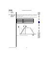
The rotary speed profile generator generates the corresponding
acceleration and deceleration ramps required to achieve the specified
speed reference value.
2
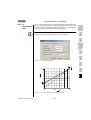
The parameter MPTYP (linear/jerk limited) and JTIME can be used to slip
linear ramps at their end points to limit the appearance of jerks.
Type of movement
dynamic, jerky
Protecting mechanics
Table 4.2
3
Setting
MPTYP = 0, linear ramp without slip
MPTYP = 3, smoothened ramp by slip by
JTIME [ms].
4
Activation of the jerk limitation
5
JTIME
6
n [1/min]
ACCR
DECR
7
t [s]
Fig. 4.1
8
Rotary speed profile generator
A
Application Manual P7000/P6000
4-3
DE
EN
FR
4 P7000/P6000 in rotary speed operation
Due to the jerk limitation the acceleration and deceleration times rise by
the slip time JTIME. The rotary speed profile is set in the PROFITOOL
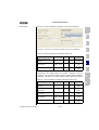
according to Fig. 4.2.
Fig. 4.2
Rotary speed profile
PROFITOOL
Value range
WE
Unit
Parameters
Acceleration
(only for speed control)
0 ... 32760
0
min-1/s
590_ACCR
(_SRAM)
Deceleration
(only for speed control)
0 ... 32760
0
min-1/s
591_DECR
(_SRAM)
Area "Reference reached"
0 ... 32760
20
min-1
230_REF_R
(_OUT)
0 ... 3
3
-
597_MPTYP
(_SRAM)
0 ... 2000
100
ms
596_JTIME
(_SRAM)
Type of profile
0: Linear ramp
3: Jerk limited ramp
1, 2: not supported
Slip
Note:
Application Manual P7000/P6000
In torque control mode no acceleration and deceleration
ramps are active. Only the slip time remains analogically
valid, i.e. it generates ramp shaped reference torque courses.
4-4
4 P7000/P6000 in rotary speed operation
Parameter 230-REF_R can be used to define a speed range in which the
actual value may differ from the reference value, without the message
"Reference value reached" (REF) becomes inactive. Reference value
fluctuations caused by reference value specification via analog inputs can
therefore be taken into account.
1
Actual value
2
+ REF_R
Setpoint
3
- REF_R
Ramp settings can be made independently from each other. A ramp
setting of zero means jump in reference value.
4
DECR
5
ACCR
4.2.2 Limitations/
Stop ramps
These functions are described in the general software functions in
chapters 6.2.2 (limitations) and 6.2.3 (stop ramps).
6
Limitations are adjustable for:
•
torque
•
rotary speed
7
Various stop ramps or reactions can be adjusted:
Application Manual P7000/P6000
•
switching off of closed-loop control
•
stop feed
•
quick stop
•
Error
8
A
4-5
DE
EN
FR
4 P7000/P6000 in rotary speed operation
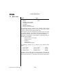
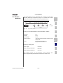
4.3
Torque control
with
reference value
via analog input
With the preset solution TCT_1 the scalable torque reference value is
specified via the analog input ISA0. The parameter settings for the analog
input are described in chapter 6.1.3, the specific settings of inputs and
outputs in chapter 4.8.
Fig. 4.3
4.4
Speed control
with
reference value
via analog input
Setting the torque control
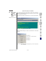
With the preset solution SCT_1 the scalable rotary speed reference value
is specified via the analog input ISA0. The parameter settings for the
analog input are described in chapter 6.1.3, the specific settings of inputs
and outputs in chapter 4.8.
see chapter 6.1.3
see chapter 4.2.1
see chapter 6.2.2
see chapter 6.2.3
Fig. 4.4
Application Manual P7000/P6000
Basic setting "Speed control, +/-10V reference value“
4-6
4 P7000/P6000 in rotary speed operation
4.5
Speed control
with
reference value
from fixed
speed table
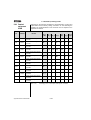
The fixed speed table is the reference source for the preset solutions
SCT_2, SCC_2 and SCB_2. There are 16 travel sets (0-15) to be entered
via the mask "Fixed speeds" from Fig. 4.6. The specific settings of inputs
and outputs for the control locations via I/O-terminals (SCT_2), CANopen
(SCC_2) or PROFIBUS (SCB_2) are described in chapter 4.8.
1
2
see chapter 4.2.1
3
see chapter 6.2.2
see chapter 6.2.3
4
Fig. 4.5
Basic setting "Speed control, fixed speeds"
5
Table of fixed speeds
6
7
8
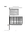
Fig. 4.6
PROFITOOL
Rotary speed
Note:
Application Manual P7000/P6000
Mask "Fixed speeds"
Value range
WE
Unit
Parameters
-32764.0 ... 32764.0
0.0
min-1
269.x-RTAB (_RTAB)
x = fixed speed 0-15
A
The rotary speed profile is the same for all fixed speed. The
realization of a variable speed profile in dependence on the
speed can be realized with a PLC-program; for an example
please refer to chapter 7.5.4.
4-7
DE
EN
FR
4 P7000/P6000 in rotary speed operation
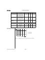
Selection of fixed speed
Fixed speeds can be selected via terminal or field bus (Profile EasyDrive
"Basic"). The number of the active fixed speed is indicated by a
parameter, and, binary coded, via the outputs (if parameterized).
The inputs planned for fixed speed selection are configured with FIxxx =
TABx. The selection is binary coded.
The binary valence (20, 21 , 22 , 23) results from the TABx-assignment.
The setting TAB0 thereby has the lowest (20), the setting TAB3 the
highest valence (23). A logic-1-level at the input activates the valence.
Changing the status of the terminal activates a new fixed speed.
Example:
IE07 IE06 IE05 IE04 IE03 IE02 IE01 IE00 IS03 IS02 IS01 IS00
TAB3 TAB2 TAB1 TAB0
=
=
=
=
23
Table 4.3
22
21
Selectable
travel sets
0-15
20
TAB1
=
TAB0
=
TAB3
=
21
20
23
0-3,
8-11
Example for the fixed speed selection via terminal
The following parameters are used to select or display the active travel
set:
Meaning
Value range
WE
Unit
Parameter
s
-
Selection of travel set fixed
speed This parameter
describes the selection via
inputs.
Field bus: Selection of a
tabular set
0 - 15
0
-
278-TIDX
(_RTAB)
-
Display parameter
Shows the currently
selected fixed speed.
0-15
0
-
776-ATIDX
(_RTAB)
PROFITOOL
With the STOP-Logics (feed enable) (terminal or bus) a progressing
movement can be stopped and restarted by application of the
programmed speed profile.
Application Manual P7000/P6000
4-8
4 P7000/P6000 in rotary speed operation
4.6
Speed control
with
reference value
and control via
field bus
With the preset solutions SCC_3 and SCB_3 the field bus is preset as
source for reference values. The specific settings on inputs and outputs
for the control locations CANopen (SCC_3) and PROFIBUS (SCB_3) are
described in chapter 4.8.
1
The reference value specification for the speed control is either
accomplished via the device internal CANopen field bus interface
(SCC_3), or via the PROFIBUS communication module (SCB_3).
2
see chapter 4.2.1
3
see chapter 6.2.2
see chapter 6.2.3
4
5
Fig. 4.7
4.6.1 CANopen
Basic setting "Speed control, reference values and control via
bus"
The drive controllers are integrated into the automation network via the
device internal electrically isolated CANopen interface X5.
Communication takes place in accordance with profile DS301. Control
and target position specification is in accordance with the proprietary
EasyDrive profile "Basic".
Note:
If a speed control in compliance with DSP402 is demanded,
the Profile-Velocity-Mode must be used for to regulate the
speed of the drive. This mode is a special form of positioning.
Please choose the presetting "PCC_1-Positioning, travel set
specification and control via CAN-Bus“.
6
7
8
A
Detailed information on configuration of the drive controller in the network
can be found in the separate documentation "CANopen data transfer
protocol".
Application Manual P7000/P6000
4-9
DE
EN
FR
4 P7000/P6000 in rotary speed operation
4.6.2 PROFIBUS
The speed specification and control via PROFIBUS requires the external
communication module ULZ-DPV1.
Control and speed specification is in accordance with the EasyDrive
profile "Basic".
Detailed information on configuration of the drive controller in a network
can be found in the separate documentation "PROFIBUS data transfer
protocol".
4.7
Speed control
with reference
value via PLC
For the preset solutions SCP_3, SCT_4 SCC_4 and SCB_4 the PLC is
preset as source of reference values. The specific settings for control
locations I/O-terminals (SCT_4), CANopen (SCC_4) and PROFIBUS
(SCB_4) are described in chapter 4.8.
ssee chapter 7
see chapter 4.2.1
see chapter 6.2.2
see chapter 6.2.3
Fig. 4.8
Basic setting "Speed control with PLC"
With these presettings the speed reference value is specified by means of
the command SET REFVAL = [x]. If the control location has also been set
to PLC (SCP_3), the command SET ENCTRL = 0/1 can be used to
switch the control off or on.
Note:
4.8
Assignment of
control terminal
Application Manual P7000/P6000
Detailed information on handling the PLC as well as
programming and operation with the PLC editor see chapter
7 "User programming".
The control terminal for the speed control is configured in dependence on
the chosen preset solution.
4-10
4 P7000/P6000 in rotary speed operation
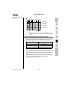
4.8.1 Terminal
assignment
P7000
Depending on the selected presetting the parameterization of inputs and
outputs differs from the factory setting, see Table 4.4. After selecting the
presetting the parameterization of the terminals can be adapted to the
application as desired.
1
Pre-set solution
I/O
Parameters
Function
TCT_1
SCT_1
SCT_2
(WE)
SCC_2 SCC_3
SCB_2 SCB_3
SCP_3
SCT_4
SCC_4
SCB_4
OFF
PLC
PLC
PLC
PLC
PLC
PLC
PLC
PLC
PLC
180-FISA0
Function selector analog
standard input ISA0+
PM10V OFF
ISA1
181-FISA1
Function selector analog
standard input ISA1+
OFF
ISD00
210-FIS00
Function selector digital
standard input ISD00
START
ISD01
211-FIS01
Function selector digital
standard input ISD01
OFF
INV
PLC
PLC
PLC
ISD02
212-FIS02
Function selector digital
standard input ISD02
OFF
TAB0
PLC
PLC
PLC
ISD03
213-FIS03
Function selector digital
standard input ISD03
OFF
TAB1
PLC
PLC
PLC
ISD04
Function selector digital
standard input ISD04
OFF
TAB2
PLC
PLC
PLC
ISD05
Function selector digital
standard input ISD05
OFF
TAB3
PLC
PLC
PLC
ISD06
Function selector digital
standard input ISD06
OFF
PLC
PLC
PLC
OSD00 240-FOS00
Function selector digital
standard input OSD00
REF
OSD01 241-FOS01
Function selector digital
standard input OSD01
ROT_0
OSD02 242-FOS02
Function selector digital
standard input OSD02
S_RDY
OSD03
Function selector digital
standard input OSD03
OFF
ISA0
Table 4.4
Application Manual P7000/P6000
OFF
OFF
OFF
2
3
4
5
6
7
8
A
Presetting the control inputs and outputs in speed controlled
operation of the P7000
4-11
DE
EN
FR
4 P7000/P6000 in rotary speed operation
4.8.2 Terminal
assignment
P6000
Depending on the selected presetting the parameterization of inputs and
outputs differs from the factory setting, see Table 4.5. After selecting the
presetting the parameterization of the terminals can be adapted to the
application as desired.
Pre-set solution
I/O
Parameters
TCT_1
SCT_1
(WE)
Function
SCT_2
ISA00
180-FISA0
Function selector analog standard
input ISA00
PM10V OFF
ISA01
181-FISA1
Function selector analog standard
input ISA01
OFF
ISD00
210-FIS00
Function selector digital standard
input ISD00
START
ISD01
211-FIS01
Function selector digital standard
input ISD01
OFF
ISD02
212-FIS02
Function selector digital standard
input ISD02
OFF
ISD03
213-FIS03
Function selector digital standard
input ISD03
OFF
OSA00 200-FOSA0
Function selector for analog output
OSA00
ACTN
OSD00 240-FOS00
Function selector digital standard
input OSD00
REF
OSD01 241-FOS01
Function selector digital standard
input OSD01
ROT_0
OSD02 242-FOS02
Function selector digital standard
input OSD02
S_RDY
Table 4.5
Application Manual P7000/P6000
SCC_2 SCC_3
SCP_3
SCB_2 SCB_3
SCT_4
SCC_4
SCB_4
OFF
PLC
PLC
PLC
PLC
PLC
PLC
OFF
OFF
OFF
PLC
PLC
PLC
PLC
PLC
TAB0
PLC
PLC
PLC
TAB1
PLC
PLC
PLC
PLC
PLC
PLC
Presetting of the control inputs and outputs with speed control
4-12
1
5 P7000/P6000 in positioning
operation
2
3
Application Manual P7000/P6000
5.1
Pre-set solutions .....................................................5-2
5.2
5.2.1
5.2.2
5.2.3
5.2.4
5.2.5
5.2.6
General functions ....................................................5-4
Positioning modes ...............................................5-5
Units and standardization .....................................5-6
Travel profile ........................................................5-9
Referencing .......................................................5-13
Limit switch .......................................................5-25
Manual operation / Jog mode .............................5-26
5.3
5.3.1
5.3.2
5.3.3
5.3.4
5.3.5
Positioning with table travel sets .........................5-28
Travel set selection ............................................5-28
Sequence of travel set selection with follow-up order
logic ..................................................................5-30
Parameterization of the travel set table ..............5-32
Switching points ................................................5-37
Teach in .............................................................5-39
5.4
5.4.1
5.4.2
Positioning and control via field bus ....................5-40
CANopen ............................................................5-40
PROFIBUS ..........................................................5-40
5.5
Positioning with PLC .............................................5-41
5.6
5.6.1
5.6.2
Assignment of control terminal ............................5-41
Terminal assignment P7000 ..............................5-42
Terminal assignment P6000 ..............................5-43
5-1
4
5
6
7
8
A
DE
EN
FR
5 P7000/P6000 in positioning operation
5.1
Pre-set
solutions
Pre-set solutions are complete parameter data sets which are provided to
handle a wide variety of typical application movement tasks.
The position controllers are automatically configured by loading a pre-set
solution into the random access memory (RAM). The parameters for
• the control location of the drive controller,
• the reference source,
• the assignment of signal processing input and outputs and
• the type of control
are the focal points of the setting.
The use of a pre-set solution considerably simplifies and shortens the
commissioning of the positioning controller. By changing individual
parameters, the preset solutions can be adapted to the needs of the
specific task. These modified pre-set solutions are saved in the device as
customized datasets. In this way, you can arrive more rapidly at your
desired movement solution.
A total of nine preset solutions covers the typical areas of application for
positioning with the closed-loop controllers.
Abbrevia
tion
PCT_2
Control location/
Reference source
Bus control profile
Additionally required
Documentation
Chapt.
Tabular travel set
I/O-terminals
5.3
-
PCC_2
Tabular travel set
CANopen field bus interface
5.3
CANopen data transfer protocol
PCB_2
Tabular travel set
Field bus communication module
(PROFIBUS)
5.3
PROFIBUS data transfer protocol
5.4
CANopen data transfer protocol
- EasyDrive Profile "TabPos"
- EasyDrive Profile "TabPos"
CANopen field bus interface
PCC_1
CANopen field bus interface
PCB_1
Field bus communication module
Field bus communication module
(PROFIBUS)
(PROFIBUS)
5.4
PROFIBUS data transfer protocol
PCP_1
PLC
PLC
5.5
see chapter 7
PCT_3
PLC
I/O-terminals
5.5
see chapter 7
PCC_3
PLC
CANopen field bus interface
5.5
CANopen data transfer protocol
PCB_3
PLC
Field bus communication module
(PROFIBUS)
5.5
PROFIBUS data transfer protocol
- DSP402-Profiles position mode
- DSP402-Profiles velocity mode
- EasyDrive-Profile "DirectPos"
- EasyDrive-Profile "ProgPos"
- EasyDrive-Profile "ProgPos"
Table 5.1
Preset solutions for positioning
All pre-set solutions have an individual window for basic settings in
PROFITOOL. Tabs contained therein differ in their general and special
functions. The general functions are listed in chapter 5.2.
Application Manual P7000/P6000
5-2
5 P7000/P6000 in positioning operation
The special functions, i. e. the reference source for the respective
presettings, are described in chapter 5.3 to 5.5.
Chapter 5.6 defines the characteristics of the control location or the
device control including the terminal assignment.
Note:
After selection of the preset solution the units and
standardization of the drive must first be adjusted, as
described in chapter 5.2.2. These are the basic requirements
for the settings following thereafter.
1
2
3
4
5
6
7
8
A
Application Manual P7000/P6000
5-3
DE
EN
FR
5 P7000/P6000 in positioning operation
5.2
General
functions
Activating the function button "Basic Settings" in PROFITOOL opens the
following window:
Fig. 5.1
Preset solution "Positioning, Travel set tables, control via terminal"
This chapter describes the types of positioning and the functions (control
buttons and tabs):
• Units and standardization
• Travel profile
• Referencing
• Limit switch
• Manual operation
Application Manual P7000/P6000
5-4
5 P7000/P6000 in positioning operation
5.2.1 Positioning
modes
Positioning is sub-divided into three different modes:
Positioning mode
Meaning
ABSOLUTE
The positioning application requires an absolute reference position
(zero). This position is either generated by referencing or by means
of a position measuring system measuring absolute values. An
absolute distance is travelled with respect to this reference position.
Relative travel tasks refer to the last target position, even if this
position has not yet been reached, e. g. when triggered during a
progressing positioning process. A new target position is thus
calculated on the following basis:
Target position (new) = Target position (old) + relative distance
1
2
3
Exceptions:
RELATIVE
-
Terminating an endless travel task with a relative travel task.
-
Releasing a follow-up task in the table of travel sets with the
effect "NEXT - Immediately, Rel.-Bez. ActPos."
Here the relative distance refers to the actual position at the time of
release. A new target position is thus calculated on the following
basis:
Target position (new) = Actual position + relative distance
Relative positioning processes do not require a reference point or no
reference travel.
ENDLESS
For endless travel tasks the drive is moved with the specified speed
(speed mode). A target position contained in this travel set is of no
meaning.
Table travel sets releasing a follow-up task with the start condition
"WSTP - Without stop from target position" are also endless travel
tasks. However, these are cancelled at the specified travel position
and transferred to the follow-up order.
An endless travel task can only be terminated with a new travel
task. Absolute travel tasks approach the new target position
directly. Relative travel tasks refer to the actual position at the time
of release.
4
5
6
7
8
A
Endless positioning processes do not require a reference point or no
reference travel.
Endless positioning can be used to realize a speed control or online
switching between positioning and speed control. The CANopen
Profile DSP402 "Profile Velocity Mode" is a form of endless
positioning.
Table 5.2
Application Manual P7000/P6000
Types of positioning
5-5
DE
EN
FR
5 P7000/P6000 in positioning operation
5.2.2 Units and
standardization
Note:
After selection of the preset solution the units and
standardization of the drive must first be adjusted. These are
the basic requirements for the settings following thereafter.
These settings can be made through the PROFITOOL.
Units
1.
For positioning the units for position, speed and acceleration can be set. If
not specified differently all positioning parameters are based on these
units. The following base units can be set:
• Translatory unit: m
• Rotary units: Degree, rev, rad, sec, min
• Special units: Incr, Steps
• Units with user defined text (max. 20 characters): User
The time basis for the speed is automatically set to [Exp*Path unit]/s, the
one for acceleration to [Exp*Path unit]/s2.
All parameters are integer values. Floating point settings are not possible.
For the input of a value lower than 1 (<1) of the base unit the exponent
must additionally be set. Base unit (e. g. [m]) and exponent (e. g. E-2)
thus determine the resulting unit (z. B. [cm]).
Fig. 5.2
Specification of units
The parameter for the resulting unit is:
PROFITOOL
Position
Application Manual P7000/P6000
Value range
WE
Unit
Parameters
-
Degree
variable
792_FGPUN (_FG)
5-6
5 P7000/P6000 in positioning operation
PROFITOOL
2.
Value range
WE
Unit
Parameters
Speed
-
Degree/s
variable
793_FGVUN (_FG)
Acceleration
-
Degree/
s2
variable
796_FGAUN (_FG)
1
After determining the units the input continues with the mechanical drive
values.
2
Feed constant and gear factor
3
The feed constant converts the specified path units into output shaft
revolutions. Furthermore, the gear transmission ratio can be entered as a
fraction. This ensures that the output shaft position is always converted to
the motor shaft without any rounding errors.
4
5
6
7
Fig. 5.3
Settings for units and standardization
PROFITOOL
Application Manual P7000/P6000
Value range
WE
Unit
Parameters
Feed constant /
Path for n revolutions
0 ... 4294967295
360
variable
789.0_FGFC
(_FG)
Feed constant /
Output shaft revolutions
0 ... 4294967295
1
-
789.1_FGFC
(_FG)
Gear/
Motor shaft revolution
0 ... 4294967295
1
-
788.0_FGGR
(_FG)
Gear/
Output shaft revolutions
0 ... 4294967295
1
-
788.1_FGGR
(_FG)
5-7
8
A
DE
EN
FR
5 P7000/P6000 in positioning operation
After the input of parameters the settings are checked by pressing
"Ready". Pressing the "Return" button brings you back to the input of
units.
Checking the settings
3.
The settings for units and standardization are checked fro plausibility and
device internal value ranges and accepted.
In very few cases the following message will appear:
Fig. 5.4
Error message caused by collision
In this case value ranges or standardizations collided in the closed-loop
control. The units and standardization assistant now suggests a different
power or exponent for the unit and will ask you to check, accept or change
this in the units window, which is directly opened upon acknowledgement.
Accepting the new setting also adapts the feed constant.
Application Manual P7000/P6000
5-8
5 P7000/P6000 in positioning operation
5.2.3 Travel profile
This mask is used to configure the limit values for the travel set, the profile
form and the travel range. The units have already been determined, see
chapter 5.2.2.
1
2
3
4
5
6
Fig. 5.5
Travel profile
7
Limit values:
PROFITOOL
Meaning
Value range
WE
Unit
Parameters
0 ... 4294967295
10000
variable
724_POSMX
(_PRAM)
0 ... 4294967295
10000
variable
722_POACC
(_PRAM)
0 ... 4294967295
10000
variable
723_PODEC
(_PRAM)
0 ... 4294967295
180
variable
757_PODMX
(_PBAS)
Hysteresis for the target position to display the
status "Target position reached". If the actual
0 ... 4294967295
position is in this window, the status will be set to
1.
100
variable
758_POWIN
(_PBAS)
Max.
speed
Maximum speed of travel set. All speeds are
limited to this value.
Max. start-up
acceleration
Max. start-up acceleration of the positioning set
Max. braking
acceleration
Max. braking acceleration of the positioning set
Max. difference between positioning reference
Permissible trailing and actual value of the profile generator An error
distance
reaction E-FLW will be executed when exceeding
(see chapter 6.9).
"Reference
reached"
window
Table 5.3
Application Manual P7000/P6000
8
A
Basic settings for travel profile
5-9
DE
EN
FR
5 P7000/P6000 in positioning operation
The buttons "Limitations" and "Stop ramps" are described under the
general software functions in chapters 6.2.2 (Limitations) and 6.2.3 (Stop
ramps).
Limitations are adjustable for:
• torque
•
rotary speed
Stop ramps or their reactions are adjustable for:
• switching off of closed-loop control
• stop feed
• quick stop
• Error
Speed override
In positioning the travel speed can be scaled online. The speed override
function with a possible scaling range from 0% - 150% of the travel speed
serves this function.
The override is set by means of the volatile parameter POOVR.
Function
Speed
override
Value range
WE
Data
types
Parameters
0 ... 150 %
100 %
usign8
(RAM)
753-POOVR
(_PBAS)
The override function is activated by:
• Changing the parameter 753-POOVR, e. g. via field bus
• Analog input FISA1 = SCALE.
The analog value is written directly to parameter 753-POOVR.
Manual changing of 753-POOVR is of no effect in this case.
• PROFIBUS EasyDrive control word "DirectPos".
The transmitted value is set directly to parameter 753-POOVR.
Manual changing of 753-POOVR is of no effect in this case.
Application Manual P7000/P6000
5-10
5 P7000/P6000 in positioning operation
Profile
PROFITOOL
Meaning
Value range
WE
Unit
Parameters
Type of profile
0: Linear acceleration profile, i.e. no jerk limitation
3: Jerk limited acceleration profile with programmed
slip time 596-JTIME
1,2: no function
0-3
3
-
597-MPTYP
(_SRAM)
Slip time with
jerk limitation
The acceleration and deceleration time increases by
the slip time. A jerk limitation is thus achieved.
Sense of
rotation
0: Normal - positive position values = clockwise
rotation of motor
1: No function
Travel range
OFF (0): Off - limited travel path, e g. for linear axes
ON (1): On - endless travel path, e g. for round axes
Definition of a circulation length is required.
For the round table configuration further
adjustment possibilities must be implemented.
1
2
0 - 2000
100
ms
596-JTIME
(SRAM)
0/1
0
-
795-FGPOL
(_FG)
OFF / ON
OFF
773-PORTA
(_PBAS)
3
4
5
Endless travel path - round table configuration
With an endless travel range, frequently referred to as round table, further
detailed settings are possible. All travel paths are in this case calculated
on a range 0 <= travel path < circulation length.
PROFITOOL
Application Manual P7000/P6000
Value range
Direction
optimization
OFF (0): Switched off
ON (1): Switched on
Further explanations see below
Reversing lock
OFF (0): No reversing lock
POS (1:) Positive sense of rotation
locked
NEG (2): Negative sense of rotation
locked
Further explanations see below
Circulation
length
Direction optimization
Meaning
OFF... ON
WE
Parameters
OFF
775_PODOP
(_PBAS)
6
7
8
OFF ... NEG
The circulation length specifies the
position range. Thereafter (in case of
0 ...
overrun) the system starts at 0
4294967295
again.
OFF
308_DLOCK
(_CTRL)
A
360
774_PONAR
(_PBAS)
With direction optimization activated an absolute target is always
approached over the shortest possible distance. Relative movements do
not take place in a path optimized way.
5-11
DE
EN
FR
5 P7000/P6000 in positioning operation
Examples for a circulation length of 360°, actual position of 0° and
absolute positioning:
Without direction optimization
With direction optimization
1) Reference value 120°:
0˚
0˚
120˚
120˚
2) Reference value 240°:
0˚
0˚
240˚
240˚
3) Reference value 600° (= 360° + 240°)
0˚
0˚
240˚
240˚
Table 5.4
Examples for a circulation length of 360°
Reversing lock
In a round table configuration a reversing lock always has priority. If the
negative sense of rotation was locked in the previous examples, the
system would always move in positive direction, even if the direction
optimization was active.
Behaviour of absolute travel
tasks
Absolute travel tasks are divided into three sections, depending on their
target position.
Travel range
Effect
Target position < circulation
The drive approaches the specified target position.
length
Target position = circulation
The drive will stop.
length
Within the range of the circulation length the drive travels to
the "Target position - (n x circulation length)".
n = integer proportion of target position/circulation length
Target position > circulation
Example:
length
Circulation length=360°, absolute target position=800°
n = 800°/360° = 2,222
Target position = 80° = 800° - 2 x 360°
Table 5.5
Application Manual P7000/P6000
Endless travel range - behaviour of absolute travel tasks
5-12
5 P7000/P6000 in positioning operation
Behaviour of relative travel
tasks
Relative travel tasks always refer to the last target position, even if this
position has not yet been reached, e. g. when triggered during a
progressing positioning process.
1
With relative travel tasks paths longer than the circulation length are
possible, if the target position exceeds the circulation length.
Example:
Circulation length = 360°; relative target position = 800°, start position =
0°
The drive performs two complete revolutions (720°) and stops during the
3rd revolution at 80° (800° - 720°).
Behaviour of endless travel
tasks
For endless travel tasks the drive is moved with the specified speed
(speed mode). A target position contained in this travel set is of no
meaning. Table travel sets releasing a follow-up task with the start
condition "WSTP - Without stop from target position" are also endless
travel tasks. However, these are cancelled at the specified travel position
and transferred to the follow-up order.
Endless travel tasks run with specified speed, irrespective of the
circulation length. When switching to the next travel set (absolute or
relative) the system moves to the new target position in the present travel
direction. An active direction optimization is thereby neglected.
Behaviour in case of travel set
changes during progressing
positioning
The travel task is changed while positioning is in progress. If, in this case,
the drive does not stop at the new target position, e. g. because of a too
long deceleration time, the drive will overshoot and return to the target
position.
If the reversing lock is in this case active the drive will brake to speed 0,
accelerate again with the defined travel profile and continue in travel
direction to the target position.
In case of overshooting a set path optimization is neglected.
5.2.4 Referencing
Referencing is performed to generate an absolute position reference
(related to the entire axis) and must normally be performed once after
switching on the mains supply. Referencing is required when running
absolute positioning processes without an absolute encoder (e. g. SSIMultiturn-Encoder). All other positioning procedures (relative, endless) do
not require referencing. For zeroizing with absolute encoders referencing
type -5 is available.
2
3
4
5
6
7
8
A
There are 41 different types, which can be set as required by the
application.
Application Manual P7000/P6000
5-13
DE
EN
FR
5 P7000/P6000 in positioning operation
By selecting the referencing (type -5 to 35) and determining the setting
−
−
−
the reference signal (positive limit switch, negative limit switch,
reference cam)
the travel direction of the drive and
the position of the zero pulse
can be defined. The referencing sequence corresponds with the
graphically displayed referencing type.
Fig. 5.6
Selection window for referencing
PROFITOOL
Meaning
Value range
WE
Referencing type
The referencing type specifies the event required
to set the reference point.
Further explanations see below.
-5 ... 35
-1
730_HOMDT
(_HOM)
Rapid motion
speed V1
Referencing speed to the first referencing event
(reference cam, zero pulse)
0 ... 4294967295
20
Degree/ 727_HOSPD
s
(_HOM)
Creep speed V2
Referencing speed from the first event for slow
approaching of the referencing position
0 ... 4294967295
20
Degree/ 727_HOSPD
s
(_HOM)
Acceleration
Acceleration during the entire referencing process
0 ... 4294967295
10
Degree/ 728_HOACC
(_HOM)
s2
Zero point offset
The reference point is always set with the
zero point offset.
-2147483648 ...
2147483647
0
Degree
Start condition
Start condition for referencing.
Further explanations see below.
OFF ... TBEN
OFF
Application Manual P7000/P6000
5-14
Unit
Parameters
729_HOOFF
(_HOM)
731_HOAUT
(_HOM)
5 P7000/P6000 in positioning operation
Table 5.6
Settings for referencing
1
Start of referencing
The start conditions can be programmed.
BUS
Setting
Effect
2
Referencing is requested via:
0
OFF
-
field bus (DSP402-Homing mode or EasyDrive control word),
level triggered (1- referencing On, 0- referencing Off)
-
Terminal (ISxx=HOMST, flank triggered 0->1)
-
PLC (command GO 0, flank triggered)
3
Referencing is started with every request.
1
2
Table 5.7
AUTO
Referencing is automatically started once when initially starting the
control. No further referencing takes place if the referencing
conditions remain unchanged for other starts of the control.
TBEN
Only valid when positioning with table travel sets.
Referencing is automatically performed once when initially selecting a
travel set. No further referencing takes place if the referencing
conditions remain unchanged for other travel set selections.
Referencing start conditions
4
5
6
Referencing type
The following describes the different types. The individual reference
points, which correspond with the zero point, are numbered in the graphs.
The different speeds (V1-rapid motion, V2-creep speed) and the
movement directions are also shown.
The four signals for the reference signal are:
•
Negative (left) hardware limit switch
•
Positive (right) hardware limit switch
•
Reference cams
•
Index signal of the encoder
7
8
A
In referencing the absolute encoders (e. g. SSI-Multiturn-Encoder) are a
special feature, because they directly create an absolute relation to the
position. Referencing with these encoders therefore does not require any
movement and, under certain conditions, energizing of the drive may also
not be necessary. However, adjustment of the zero point is still necessary.
The type -5 is particularly suitable for this purpose.
Application Manual P7000/P6000
5-15
DE
EN
FR
5 P7000/P6000 in positioning operation
Type -5, absolute encoder
This type is particularly suitable for absolute encoders (e. g. SSIMultiturn-Encoder). Referencing takes place immediately after switching
the mains supply on, which means that it can also be activated in deenergized state.
The current position complies with the zero point. The zero position is
calculated on basis of the absolute encoder position + zero point offset.
According to this, referencing with zero point offset = 0 supplies the
absolute position of the SSI-encoder, e.g. in operation of a SSI-MultiturnEncoder. Another referencing with unchanged setting of the zero point
offset does not cause a change in position.
Referencing or zero point adjustment for the system must be performed
as follows
1. Enter zero point offset = 0
2. Referencing (start referencing) delivers the absolute position of the
sensor
3. Move drive to reference position (zero point of machine)
4. At this point enter the zero point offset (the value by which the
position is to be changed with respect to the displayed position)
5. Repeat referencing (start referencing)
6. Save the setting (zero point offset)
7. The system will be automatically referenced when switching the
mains supply on. Manual referencing is no longer necessary.
Type -4, continuous
referencing, neg. reference
cams
Like referencing type 22, with subsequent possibility of continuous
referencing. Further explanations under "Type -3".
Type -3, continuous
referencing, pos. reference
cams
Like referencing type 20,
referencing.
with subsequent possibility of continuous
Types "-3" and "-4" can only be used with endless travel range (773PORTA=ON). They serve the fully automatic compensation of slippage or
inaccurate transmission ratio. After initial referencing the actual position is
overwritten with the zero point offset at every rising flank of the reference
cam. The path still to be travelled is corrected, the axis is thus able to
perform any number of relative movements to one direction without
drifting off, even with drives susceptible for slippage.
The circulation length (774-PONAR) must come as close as possible to
the path between two reference signals. With other words: E.g., the same
position must be indicated after one circulation, as otherwise disturbing
movements may occur during a correction. The permissible trailing
distance (757-PODMX) must be bigger than the maximum mechanical
inaccuracy.
Application Manual P7000/P6000
5-16
5 P7000/P6000 in positioning operation
Attention: The correction of the actual position takes place in form of
jumps. No acceleration ramps are active. The correction is
this dealt with like a trailing error compensation. The
maximum speed during the correction process can be
adjusted under the function "Limitations" (see chapter 6.2.2).
Here the maximum speed of the positioning travel profile is
not active.
Type -2, no referencing
No referencing is performed. The zero point offset is added to the current
position. During initial switching on of the power stage the status
"referencing completed" is set.
This type is most suitable for absolute encoders, as long as no zeroizing
is required. For zeroizing you should select type -5.
Type -1, actual position = 0
The actual position corresponds with the zero point, it is set to 0, i. e. the
closed-loop control runs a actual position reset. The zero point offset is
added.
Type 0
Not defined.
Type 1, negative limit switch
and index signal
The initial movement takes place according to Fig. 5.7 in direction of the
negative (left) hardware limit switch (this switch is inactive) and the
direction of movement is reversed with active flank. The first index signal
after the descending flank corresponds with the zero point.
1
2
3
4
5
6
7
v1
v2 1
8
Index signal
negative limit switch
Fig. 5.7
Application Manual P7000/P6000
Type 1, negative limit switch and index signal
5-17
A
DE
EN
FR
5 P7000/P6000 in positioning operation
Type 2, negative limit switch
and index signal
The initial movement takes place according to Fig. 5.8 in direction of the
positive (right) hardware limit switch (this switch is inactive) and the
direction of movement is reversed with active flank. The first index signal
after the descending flank corresponds with the zero point.
v1
2
v2
Index signal
positive limit switch
Fig. 5.8
Type 3+4, positive limit switch
and index signal
Type 2, negative limit switch and index signal
The initial movement takes place according to Fig. 5.9 in direction of the
positive (right) hardware limit switch, if the reference cam is inactive, see
symbol A in Fig. 5.9.
As soon as the reference cam becomes active, the direction of movement
will be reversed for type 3.
The first index signal after the descending flank corresponds with the zero
point. For type 4 the first index signal after the ascending flank
corresponds with the zero point.
The initial movement takes place in direction of the negative (left)
hardware limit switch and the reference cam is active, see symbol B in
Fig. 5.9.
Application Manual P7000/P6000
5-18
5 P7000/P6000 in positioning operation
If the reference cam becomes inactive, the first index signal of type 3
will correspond with the zero point. With type 4 the movement direction
will change as soon as the reference cam becomes inactive. The first
index signal after the ascending flank corresponds with the zero point.
1
2
v1
3
A
v2
v2
3
B
4
v2
3
v1
v2
4
4
Index signal
Reference cams
Fig. 5.9
Type 5+6, negative limit switch
and index signal
5
Type 3+4, positive limit switch and index signal
The initial movement takes place in direction of the positive (right)
hardware limit switch and the reference cam is active, see symbol A in
Fig. 5.10.
6
For type 5 the first index signal after the descending flank corresponds
with the zero point. When the reference cam becomes inactive, the
direction of movement with type 6 will be reversed and the first index
signal after the ascending flank corresponds with the zero point.
7
The initial movement takes place in direction of the negative (left)
hardware limit switch and the reference cam is inactive, see symbol B in
Fig. 5.10.
8
A
Application Manual P7000/P6000
5-19
DE
EN
FR
5 P7000/P6000 in positioning operation
With type 5 the direction of movement is reversed as soon as the
reference cam becomes active, and the first index signal after the
descending flank corresponds with the zero point. For type 6 the first
index signal after the ascending flank corresponds with the zero point.
v2
5
v1
A
v2
v1
6
6
5
B
v2
v2
Index signal
Reference cams
Fig. 5.10
Type 7 to 10, reference cams,
index signal and positive limit
switch
Type 5+6, negative limit switch and index signal
The initial movement is in direction of the positive (right) hardware limit
switch. Limit switch and reference cam are inactive, see symbol A in Fig.
5.11.
Type 7 changes the direction of movement after the active reference cam.
The first index signal after the descending flank corresponds with the zero
point. With type 8 the zero point corresponds with the first index signal
with active reference cam. Type 9 changes the direction of movement, if
the reference cam has been overtravelled. The zero point corresponds
with the first index signal after the ascending flank. With type 10 the
reference cam is overtravelled and the first index signal after this
corresponds with the zero point.
The initial movement is in direction of the negative (left) hardware limit
switch. The positive limit switch is inactive and the reference cam is
active, see symbol B in Fig. 5.11.
With type 7 the zero point corresponds with the first index signal after
descending flank of the reference cam. Type 8 changes the direction of
movement after descending flank of the reference cam. The zero point
corresponds with the first index signal after the ascending flank of the
reference cam.
The initial movement is in direction of the positive (right) hardware limit
switch. The limit switch is inactive and the reference cam is active, see
symbol C in Fig. 5.11.
Application Manual P7000/P6000
5-20
5 P7000/P6000 in positioning operation
Type 9 changes the direction of movement, if the reference cam is
inactive. The zero point corresponds with the first index signal after the
ascending flank. With type 10 the first index signal is the zero point after
descending flank of the reference cam.
The initial movement is in direction of the positive (right) hardware limit
switch. Limit switch and reference cam are active. As soon as the positive
limit switch becomes active the direction of movement will change, see
symbol D in Fig. 5.11.
With type 7 the first index signal after overtravelling the reference cam
corresponds with the zero point.
Type 8 changes the direction of movement, if the reference cam has been
overtravelled. The zero point corresponds with the first index signal after
the ascending flank. With type 9 the zero point corresponds with the first
index signal with active reference cam. Type 10 changes the direction of
movement after the active reference cam. The first index signal after the
descending flank corresponds with the zero point.
1
2
3
4
5
A
v1
v1
8
10
9 v2
7 v2
B C
v2
7
v2
v2
v2
9
8
6
10
v2
v1
7
v2
v1
v2 8
v1
9
v2
D
7
10
Index signal
8
Reference cams
positive limit switch
Fig. 5.11
Type 11 to 14, reference cams,
index signal and negative limit
switch
A
Type 7 to 10, reference cams, index signal and positive limit switch
The initial movement is in direction of the negative (left) hardware limit
switch. Limit switch and reference cam are inactive, see symbol A in Fig.
5.12.
Type 11 changes the direction of movement after the active reference
cam. The first index signal after the descending flank corresponds with
the zero point. With type 12 the zero point corresponds with the first index
signal with active reference cam.
Application Manual P7000/P6000
5-21
DE
EN
FR
5 P7000/P6000 in positioning operation
Type 13 changes the direction of movement, if the reference cam has
been overtravelled. The zero point corresponds with the first index signal
after the ascending flank.
With type 14 the reference cam is overtravelled and the first index signal
after this corresponds with the zero point.
The initial movement is in direction of the negative (left) hardware limit
switch. The limit switch is inactive and the reference cam is active, see
symbol B in Fig. 5.12.
Type 13 changes the direction of movement, if the reference cam is
inactive. The zero point corresponds with the first index signal after the
ascending flank. With type 14 the first index signal is the zero point after
descending flank of the reference cam.
The initial movement is in direction of the positive (right) hardware limit
switch. The negative limit switch is inactive and the reference cam is
active, see symbol C in Fig. 5.12.
With type 11 the zero point corresponds with the first index signal after
descending flank of the reference cam. Type 12 changes the direction of
movement after descending flank of the reference cam. The zero point
corresponds with the first index signal after the ascending flank of the
reference cam.
The initial movement is in direction of the negative (left) hardware limit
switch. Limit switch and reference cam are active. As soon as the
negative limit switch becomes active the direction of movement will
change, see symbol D in Fig. 5.12.
With type 11 the reference cam must be overtravelled, so that the first
index signal corresponds with the zero point.
Type 12 changes the direction of movement, if the reference cam has
been overtravelled. The zero point corresponds with the first index signal
after the ascending flank.
With type 13 the zero point corresponds with the first index signal with
active reference cam.
Application Manual P7000/P6000
5-22
5 P7000/P6000 in positioning operation
Type 14 changes the direction of movement after the active reference
cam. The first index signal after the descending flank corresponds with
the zero point.
14
v2
v1
v2 13
v2
14
D
v2
v1
B C
A
v2 11
v2
12
13
2
11
v2
v1
13
v1
v1
12
1
3
11
12 v2
14 v2
4
Index signal
Reference cams
5
positive limit switch
Fig. 5.12
Type 11 to 14, reference cams, index signal and negative limit switch
Type 15 and 16
These types of referencing are not defined.
Type 17 to 30, reference cams
Referencing types 17 to 30 are similar to types 1 to 14. The zero point
determination does not depend on the index signal, but solely on the
reference cams or the limit switches.
7
8
v1
19
v2
v2
19
v2
6
A
20
v1
v2
20
Reference cams
Fig. 5.13
Application Manual P7000/P6000
Type 17 to 30, reference cams
5-23
DE
EN
FR
5 P7000/P6000 in positioning operation
Type 1
analog
Type 17
...
Type 4
analog
Type 20
...
Type 8
analog
Type 24
...
Type 12
analog
Type 28
...
Type 14
Table 5.8
analog
Type 30
Type analogy for the individual types of referencing
Type 31 and 32
These types of referencing are not defined.
Type 33 and 34, index signal
The zero point corresponds with the first index signal in direction of
movement.
v2
33
v2
34
Index signal
Fig. 5.14
Type 35
Application Manual P7000/P6000
Type 33 and 34, index signal
The current position complies with the zero point. No reset is performed.
5-24
5 P7000/P6000 in positioning operation
5.2.5 Limit switch
Software limit switch
The software limit switches are only valid for positioning. They only
become active after successful referencing.
1
The software limit switches are only activated by identical setting (limit
switch+ = limit switch- = 0).
2
3
4
5
PROFITOOL
Meaning
Value range
WE
Unit
Parameters
Positive
Software limit switch
in positive sense of
rotation
-2147483648 ...
2147483647
0
variable
759-SWLSP
(_PBAS)
Negative
Software limit switch
in negative sense of
rotation
-2147483648 ...
2147483647
0
variable
760-SWLSN
(_PBAS)
6
7
The behaviour or reaction depends on the parameterized fault reaction
(see chapter 6.9) and the positioning mode.
Positioning mode
Behaviour/reaction
Absolute
Before releasing an absolute travel task the system will
check whether the target is in the valid range, meaning
inside the range of the software limit switches. If the
target is outside the limits no travel order will be
submitted and the programmed fault reaction acc. to 543R-SWL will be performed.
Relative
Endless
(speed controlled)
Table 5.9
Application Manual P7000/P6000
8
A
The drive moves until a software limit switch is detected.
After this the programmed fault reaction acc. to 543-RSWL is performed. A rapid stop is also performed
with reactions of R-SWL=NOERR or WARN
Behaviour of the software limit switches
5-25
DE
EN
FR
5 P7000/P6000 in positioning operation
Hardware limit switch
The hardware limit switches are valid for all types of closed-loop control.
They are connected via drive controller inputs. For this purpose two
inputs must be set up as described in chapter 6.1.1.
5.2.6 Manual
operation / Jog
mode
Manual operation/Jog mode is only valid for positioning. With jog mode
activated the drive is operated in speed controlled mode (endless).
For manual operation two different jog speeds can be set. These can be
activated via the window PROFITOOL Manual operation or via terminal
and field bus. This activation requires that the drive is stopped.
PROFITOOL
Jog mode via terminal or field
bus
Application Manual P7000/P6000
Value range
Speed
Rapid motion
0 ...4294967295
Speed
Creep speed
0 ...4294967295
WE
Unit
Parameters
1000
variable
721_VQJOG (_PRAM )
500
variable
720_VSJOG (_PRAM )
In jog mode the drive is controlled by means of two signals or inputs,
either in positive or negative direction. If one of these signals becomes
active while the control is active, the drive will move with creep speed.
Rapid motion is activated by operating the second jog input also in creep
speed status. If the first signal is deactivated in rapid motion, the drive will
stop. If it is set again, the drive will again move with creep speed, even if
rapid motion had been requested. An example for a jog sequence in
positive travel direction is shown in Table 5.10.
5-26
5 P7000/P6000 in positioning operation
Ser.-No.
Signal
TIPP
Signal
TIPN
1.
0
0
Standstill
2.
1
0
Creep speed
3.
1
1
Rapid motion
Status of axis
4.
0
1
Standstill
5.
1
1
Creep speed
6.
1
0
Creep speed
7.
1
1
Rapid motion
8.
1
0
Creep speed
9.
0
0
Standstill
Table 5.10
1
2
3
4
Example jog operation in positive direction
5
6
7
8
A
Application Manual P7000/P6000
5-27
DE
EN
FR
5 P7000/P6000 in positioning operation
5.3
Positioning with
table travel sets
For the preset solutions PCT_2, PCC_2 and PCB_2 the travel set table is
preset as setpoint source. The specific settings of the control via I/Oterminals or field bus are described in chapter 5.6. If the drive is
controlled via field bus, the special proprietary EasyDrive protocol
"TablePos" is used.
There are 16 travel sets (0-15). A travel set consists of:
1. Target position
2. Mode for absolute/relative/endless positioning
3. Speed
4. Start-up acceleration
5. Braking deceleration
6. Repetition of a relative travel set
7. Follow-up order logics with various provisional conditions. Follow-up
orders enable the realization of small automated sequence
programs.
8. Travel set dependent switching points, see chapter 5.3.4
A slip time in ms programmed in the travel profile serves as jerk limitation.
It applies for all travel sets. The travel sets can only be set via the PC
desktop PROFITOOL or field bus.
Note:
5.3.1 Travel set
selection
The travel sets have the predefined standard units. Before
parameterizing the travel sets you must therefore first set the
units and the standardization, see chapter see chapter 5.2.2.
Travel sets can be selected and activated via terminal or field bus. The
number of the active travel set is indicated by a parameter, and, binary
coded, via the outputs (if parameterized).
The inputs planned for travel set selection are configured with FIxxx =
TABx, see example in Table 5.11. The selection is binary coded.
The binary valence (20, 21 , 22 , 23) results from the TABx-assignment.
The setting TAB0 thereby has the lowest (20), the setting TAB3 the
highest valence (23). A logic-1-level at the input activates the valence.
Application Manual P7000/P6000
5-28
5 P7000/P6000 in positioning operation
Example:
IE07 IE06 IE05 IE04 IE03 IE02 IE01 IE00 IS03 IS02 IS01 IS00
TAB3 TAB2 TAB1 TAB0
=
=
=
=
23
Table 5.11
22
21
Selectable
travel sets
0-15
20
TAB2
=
TAB1
=
TAB0
=
22
21
20
TAB1
=
TAB0
=
TAB3
=
21
20
23
2
0-7
0-3,
8-11
Example for the travel set selection via terminal
A separate release signal (see Table 5.12) via an input or the field bus
(trigger) is required to activate a travel set via terminal. The selection of a
new table index and thus a new travel task will interrupt the ongoing
positioning process or the follow-up order logic.
Control
location
Signal
Input FIxxx = TBEN
Input FIxxx = FOSW
Next start
Effect like "TBEN", if a follow-up order is started
but no follow-up order is available or waiting.
FOSW will then start the next selected travel set.
Bit
"Perform travel task"
Release of selected travel set
The selection of a new table index and thus a new
travel task will always interrupt the ongoing
positioning process or the follow-up order logic.
Bit
"Repetition/perform
follow-up order"
Next start
Effect like bit "Perform follow-up task", if a followup order is started but no follow-up order is
available or waiting. FOSW will then start the next
selected travel set.
Field bus
Application Manual P7000/P6000
3
4
5
Comment
Release of selected travel set
The selection of a new table index and thus a new
travel task will always interrupt the ongoing
positioning process or the follow-up order logic.
I/O-terminal
Table 5.12
1
6
7
8
A
Release signal for new travel set
5-29
DE
EN
FR
5 P7000/P6000 in positioning operation
The following parameters are used to select or display the active travel
set:
PROFITOOL
Meaning
Value range
WE
Unit
Parameters
-
Travel set selection.
This parameter describes
the selection via inputs.
0 - 15
0
-
278-TIDX
(_RTAB)
-
Display parameter
Shows the currently
processed travel set.
0-15
0
-
776-ATIDX
(_RTAB)
With the HALT-Logic (Enable feed) (terminal or bus) a progressing
positioning can be interrupted either with the programmed or the quick
stop ramp (see chapter 6.2.3) and subsequently continued again.
5.3.2 Sequence of
travel set
selection with
follow-up order
logic
The sequence of travel set editing is prioritized:
1. Execution of the selected travel set
2. Execution of repetition with relative travel sets
Repetitions are performed with parameterizable start conditions. The
start conditions are identical with the ones of the follow up order.
3. Jump to the next travel set
The follow-up order is performed with parameterizable start
conditions. The start conditions are identical with the ones for the
repetitions.
Activation of a travel set always interrupts this sequence.
Application Manual P7000/P6000
5-30
5 P7000/P6000 in positioning operation
This sequence is shown in Fig. 5.15
1
Start
Select
travel set
Execure
travel set
2
3
4
Yes
Repeat?
No
Yes
Following
order
No
End
Fig. 5.15
5
6
7
Sequence of travel set selection with follow-up order logic
8
A
Application Manual P7000/P6000
5-31
DE
EN
FR
5 P7000/P6000 in positioning operation
5.3.3 Parameterization
of the travel set
table
Target position
The target position can be parameterized in a user defined path unit.
PROFITOOL
Target position
Value range
WE
Unit
Parameters
-2147483648 ...
2147483647
0
variable
272.x-PTPOS
(_RTAB)
x = travel set 0-15
Mode
The mode defines the relation to the target position. In this context please
observe the notes in chapter 5.2.1-"Positioning modes".
PROFITOOL
Mode
Application Manual P7000/P6000
Value range
WE
ABS ... SPEED
REL
5-32
Unit
Parameters
274.x_PTMOD
(_RTAB)
x = travel set 0-15
5 P7000/P6000 in positioning operation
Mode settings:
BUS
Setting
Effect
0
ABS
The target position always refers to a fixed reference zero
point.
1
REL
A relative travel task always refers to a variable position.
Depending on the start conditions for repeat or follow-up
order this may either be the last target position or the current
position.
2
2
SPEED
The axis moves with the speed profile programmed in the
selected travel set. The target position is of no relevance.
3
1
Speed
4
The speed can be specified signed A negative setting is only evaluated in
case of an endless positioning. The speed is limited by the maximum
speed in the travel profile.
PROFITOOL
Speed
Value range
WE
Unit
Parameters
-2147483648 ...
2147483647
1000
variable
273.x_PTSPD
(_RTAB)
x = travel set 0-15
Acceleration
The acceleration values for starting and braking can be parameterized
irrespective of each other. The input 0 means that the acceleration will
take place with maximum ramp steepness or maximum torque. The
acceleration values are limited by the maximum values in the travel
profile.
Application Manual P7000/P6000
PROFITOOL
Value range
WE
Unit
Parameters
Start-up acceleration
0 ... 4294967295
10000
variable
276.x_PTACC
(_RTAB)
x = travel set 0-15
Braking acceleration
0 ... 4294967295
10000
variable
277.x_PTDEC
(_RTAB)
x = travel set 0-15
5-33
5
6
7
8
A
DE
EN
FR
5 P7000/P6000 in positioning operation
Repetition
A travel set with relative positioning can be repeated several times with
the programmed value. Like the follow-up order, the repetitions of the
travel set are started in dependence on the start condition. The execution
of possible repetitions has priority over the execution of a follow-up order.
PROFITOOL
Value range
WE
0 ... 255
0
Repetition
Unit
Parameters
762.x_FOREP
(_RTAB)
x = travel set 0-15
Follow-up order
The parameterization of a follow-up order for a travel set enables the
realization of small automated sequential programs.
The setting "-1" signalizes that no further travel set (follow-up order) is to
be activated.
PROFITOOL
Follow-up order
Value range
WE
-1 ... 15
-1
Unit
Parameters
761.x_FONR
(_RTAB)
x = travel set 0-15
Start condition - activating condition "WANN"
This start condition can be used to adjust when a travel set is to be
repeated or the follow-up order is to be activated.
PROFITOOL
Value range
WE
Start condition
SW ... WSTP
SW
Unit
Parameters
764.x_FOST
(_RTAB)
x = travel set 0-15
Description of setting:
Application Manual P7000/P6000
BUS
Setting
0
SW
Meaning
Switch- digital input or control bit starts the sequence
5-34
5 P7000/P6000 in positioning operation
BUS
Setting
1
DT
The repetition or the follow-up order is started with a
programmable delay time after the target position has been
reached.
2
SW-DT
A repetition or the follow-up order is started via a digital input
or control bit, but at the latest after a defined delay time.
WSTP
The drive moves to the target position with speed v1 of the
current travel set and then accelerates "on the fly" (without
stop) to V2 or the repetition or the follow-up order.
3
Meaning
1
2
3
Effect start condition - activation condition "WIE"
The "WIE"-condition is parameterized in dependence on the setting of the
previously selected "WANN"-activation condition:
PROFITOOL
Effect of start signal
Start condition = SW:
Value range
WE
OFF ... NEXT
OFF
Unit
Parameters
765.x_FOSWC
(_RTAB)
x = travel set 0-15
Activation of the follow-up order or repetition is flank triggered (HighLevel). The effect of a start signal during a running positioning process
can be parameterized, see Table 5.13.
Bus
Setting
0
OFF
1
2
Meaning
Signals occurring during an ongoing positioning process are ignored.
Thus a signal never interrupts a running travel task.
STORE
Signals occurring during an ongoing positioning process cause an
immediate change of the current target position. A relative proportion is
added to the previous target position and approached without
intermediate stop. The number of follow-up orders to be executed
depends on the accumulated signal flanks. This function is useful for
relative positioning.
NEXT
Signals occurring during an ongoing positioning process cause an
immediate change of the current target position. A relative proportion is
added to the actual position at the time of the change and approached
without intermediate stop. This position is most suitable for
compensation of a residual path.
Table 5.13
4
5
6
7
8
A
Effect of start condition for repetition and follow-up order
If no travel set is being processed or no repetition active, the signal to
activate the follow-up order will start the travel set, that has been selected
via terminal or field bus system. See “Travel set selection”, page 5-28.
Start condition = SW-DT:
Application Manual P7000/P6000
The parameters effect start signal (FOSWC) in Table 5.13 and the delay
time (FODT) must be set.
5-35
DE
EN
FR
5 P7000/P6000 in positioning operation
Delay time
This field will only become active if the delay time (DT, SW-DT) for the
follow-up order has been selected under start condition.
PROFITOOL
Delay time
Example travel set linkage with
follow-up order logic
Value range
WE
Unit
Parameters
0 ... 65535
0
ms
763.x_FODT
(_RTAB)
x = travel set 0-15
The following picture shows two examples for positioning with follow-up
order (travel set 2).
v
1
v1
FOST = SW, DT or SW-DT
v2
t
Travel set 1
FOST = WSTP
v
2
Travel set 2
v1
aDEC2
v2
t
Travel set 1
Travel set 2
Switching point A and B
Two switching points can be evaluated per travel set. Switching points 0-3
are selected via two parameters. The entry 0 does not select a switching
point (inactive).
Application Manual P7000/P6000
PROFITOOL
Value range
WE
Switching point A
0 ... 4
0
771.x_PTSP1
(_RTAB)
x = travel set 0-15
Switching point B
0 ... 4
0
772.x_PTSP2
(_RTAB)
x = travel set 0-15
5-36
Unit
Parameters
5 P7000/P6000 in positioning operation
5.3.4 Switching
points
Four switching points can be defined. Each switching point can modify up
to three markers. The switching points can be used in all travel sets. A
maximum of two switching points can be used in each travel set.
Configuration takes place via the travel set dependent switching point
configuration. Each switching point has the following settings.
1
2
3
4
5
Target position
The target position is effective in dependence on the switching point
mode and its linkage with a travel set.
PROFITOOL
Target position
Value range
WE
Unit
Parameters
0
variable
766.x_CPOS
(_RTAB)
x = switching point 0-3
-2147483648 ...
2147483647
6
7
8
A
Application Manual P7000/P6000
5-37
DE
EN
FR
5 P7000/P6000 in positioning operation
Mode
PROFITOOL
Value range
WE
Mode
ABS ... RELE
ABS
Unit
Parameters
767.x_CREF
(_RTAB)
x = switching point 0-3
Setting of mode:
BUS
Setting
Meaning
0
ABS
The switching point refers to the reference position or the
absolute position of the system.
1
RELS
Relative to the travel set start position: Switching point
responds after a relative path related to the start position.
2
RELE
Relative to the travel set end position: The switching point
responds after a relative path before reaching the end
position.
Marker
PROFITOOL
Value range
WE
Marker 1
OFF ... INV
OFF
768.x_CM1CF
(__RTAB )
x = switching point 0-3
Marker 2
OFF ... INV
OFF
769.x_CM2CF
(__RTAB )
x = switching point 0-3
Marker 3
OFF ... INV
OFF
770.x_CM3CF
(__RTAB )
x = switching point 0-3
Marker function:
Application Manual P7000/P6000
BUS
Setting
Meaning
0
OFF
inactive
1
SET
Marker is set to 1
2
CLEAR
Marker is set to 0
3
INV
Marker is inverted
5-38
Unit
Parameters
5 P7000/P6000 in positioning operation
5.3.5 Teach in
PROFITOOL:
The actual position is transferred to the corresponding table by means of
the PROFITOOL.
1
1. Opening of the manual mode window and selection of the tab "Travel
set table".
2. Moving the drive to the position to be learned.
2
3. Enter the travel set number in the manual mode window and click on
button "Accept".
3
4
5
6
7
Fig. 5.16
Teach-In via PROFITOOL
8
Terminals:
If an input is parameterized for "Teach in" (FIxx = TBTEA), the current
position is transferred to the travel set in the table as target position, with
ascending flank.
Application Manual P7000/P6000
5-39
A
DE
EN
FR
5 P7000/P6000 in positioning operation
5.4
Positioning and
control via field
bus
With the preset solutions PCC_1 and PCB_1 the field bus is the reference
source. The specific settings of the I/O-terminals is described in chapter
5.6.
Positioning via field bus either takes place via the device internal CANopen
field bus interface, or via the PROFIBUS communication module. All
general positioning functions, as described under 5.2, can be used.
5.4.1 CANopen
The drive controller is integrated into the automation network via the
device internal electrically isolated CANopen interface X5.
Communication takes place in accordance with profile DS301.
Furthermore, a standardized communication with the device profile for
drives with changeable speed DSP402 is assured. The following profiles
are supported:
• Homing Mode (referencing) with 41 different types
• Profile-Position-Mode for direct travel set specification with device
internal jerk-limited profile generation
• Profile-Velocity-Mode for speed regulation of the drive. This is a
special positioning mode, solely used for endless travelling. A target
position is of no relevance.
Online switching between modes, i.e. with active control, is possible. In
addition, standardizations and units are applied according to the FactorGroup and the control according to the DRIVECOM-status machine.
Detailed information on configuration of the drive controller in the network
can be found in the separate documentation "CANopen data transfer
protocol".
5.4.2 PROFIBUS
The travel set specification and control via PROFIBUS requires the
external communication module ULZ-DPV1.
Control and target position specification is in accordance with the
EasyDrive profile "DirectPos".
Detailed information on configuration of the drive controller in the network
can be found in the separate documentation "PROFIBUS data transfer
protocol".
Application Manual P7000/P6000
5-40
5 P7000/P6000 in positioning operation
5.5
Positioning with
PLC
For the preset solutions PCP_1, PCT_3, PCC_3 and PCB_3 the PLC is
preset as source of reference values. The specific settings on inputs and
outputs for the control locations PLC (PCP_1), terminal (PCT_3),
CANopen (PCC_3) or PROFIBUS (PCB_3) are described in chapter 5.6.
With these presettings the various positioning commands GO [x] and
STOP [x]. can be used. If the control location has also been set to PLC
(PCP_1), the command SET ENCTRL = 0/1 can be used to switch the
control off or on.
All general positioning functions, as described under 5.2, can be used.
The travel set table can be called up via a special positioning commands
GO T [x]. Automatic linkage via repetitions and follow-up orders as well as
the switching points cannot be used when specifying reference values via
PLC.
If the drive is controlled via field bus, the special proprietary EasyDrive
protocol "ProgPos" is used.
Detailed information on handling the PLC as well as programming and
operation with the PLC editor see see chapter 7 "User programming".
5.6
Assignment of
control terminal
The control terminal for positioning is configured in dependence on the
chosen preset solution.
1
2
3
4
5
6
7
8
A
Application Manual P7000/P6000
5-41
DE
EN
FR
5 P7000/P6000 in positioning operation
5.6.1 Terminal
assignment
P7000
Depending on the selected presetting the parameterization of inputs and
outputs differs from the factory setting, see Table 5.14. After selecting the
presetting the parameterization of the terminals can be adapted to the
application as desired.
Pre-set solution
I/O
Parameters
Function
SCT_1
(WE)
PCC_1
PCP_1
PCB_1
PCT_2
PCC_2
PCB_2
PCT_3
PCC_3
PCB_3
ISA0
180-FISA0
Function selector analog standard
input ISA0+
PM10V OFF
PLC
OFF
OFF
PLC
PLC
ISA1
181-FISA1
Function selector analog standard
input ISA1+
OFF
PLC
OFF
OFF
PLC
PLC
ISD00
210-FIS00
Function selector digital standard
input ISD00
START
OFF
PLC
START
OFF
RECAM PLC
ISD01
211-FIS01
Function selector digital standard
input ISD01
OFF
RECAM RECAM TBEN
ISD02
212-FIS02
Function selector digital standard
input ISD02
OFF
PLC
TAB0
PLC
PLC
ISD03
213-FIS03
Function selector digital standard
input ISD03
OFF
PLC
TAB1
PLC
PLC
ISD04
Function selector digital standard
input ISD04
OFF
PLC
TAB2
PLC
PLC
ISD05
Function selector digital standard
input ISD05
OFF
PLC
TAB3
PLC
PLC
ISD06
Function selector digital standard
input ISD06
OFF
PLC
PLC
PLC
OSD00 240-FOS00
Function selector digital standard
input OSD00
REF
OSD01 241-FOS01
Function selector digital standard
input OSD01
ROT_0
OSD02 242-FOS02
Function selector digital standard
input OSD02
S_RDY
OSD03
Function selector digital standard
input OSD03
OFF
Table 5.14
Application Manual P7000/P6000
RECAM PLC
Presetting of the control inputs and outputs on P7000
5-42
RECAM
5 P7000/P6000 in positioning operation
5.6.2 Terminal
assignment
P6000
Depending on the selected presetting the parameterization of inputs and
outputs differs from the factory setting, see Table 5.15. After selecting the
presetting the parameterization of the terminals can be adapted to the
application as desired.
1
Pre-set solution
I/O
Parameters
Function
SCT_1
(WE)
PCC_1
PCP_1
PCB_1
PCT_2
PCC_2
PCB_2
PCT_3
PCC_3
PCB_3
OFF
OFF
PLC
PLC
PLC
PLC
180-FISA0
Function selector analog standard
input ISA00
PM10V OFF
PLC
ISA01
181-FISA1
Function selector analog standard
input ISA01
OFF
PLC
ISD00
210-FIS00
Function selector digital standard
input ISD00
START
ISD01
211-FIS01
Function selector digital standard
input ISD01
OFF
PLC
FOSW
PLC
PLC
ISD02
212-FIS02
Function selector digital standard
input ISD02
OFF
PLC
TAB0
PCL
PCL
ISD03
213-FIS03
Function selector digital standard
input ISD03
OFF
OSA00 200-FOSA0
Function selector for analog output
OSA00
ACTN
OSD00 240-FOS00
Function selector digital standard
input OSD00
REF
OSD01 241-FOS01
Function selector digital standard
input OSD01
ROT_0
OSD02 242-FOS02
Function selector digital standard
input OSD02
S_RDY
ISA00
Table 5.15
OFF
PLC
OFF
PLC
2
3
4
5
HOMSW HOMSW HOMSW HOMSW HOMSW HOMSW
PLC
PLC
PLC
6
7
8
Presetting of the control inputs and outputs on P6000
A
Application Manual P7000/P6000
5-43
DE
EN
FR
5 P7000/P6000 in positioning operation
Application Manual P7000/P6000
5-44
1
6
General software functions
2
3
Application Manual P7000/P6000
6.1
6.1.1
6.1.2
6.1.3
6.1.4
Inputs and outputs ..................................................6-3
Digital inputs .......................................................6-4
Digital outputs ..................................................6-13
Analog inputs .....................................................6-23
Analog output for P6000 ....................................6-29
6.2
6.2.1
6.2.2
6.2.3
6.2.4
6.2.5
6.2.6
6.2.7
Setpoint generation ...............................................6-32
Rotary speed profile ...........................................6-33
Limitations .........................................................6-34
Stop ramps ........................................................6-36
Reference encoder/Master-Slave operation ........6-39
Setpoint structure - further settings/control
location ..............................................................6-46
Control location ..................................................6-55
Motor potentiometer function .............................6-58
6.3
Motor control .........................................................6-62
8
6.4
6.4.1
6.4.2
6.4.3
6.4.4
Motor and transducer ...........................................6-67
Motor data .........................................................6-67
Encoder .............................................................6-74
Motor protection ................................................6-83
Motor holding brake ...........................................6-90
A
6.5
6.5.1
6.5.2
Bus systems ........................................................6-100
CANopen ..........................................................6-100
PROFIBUS ........................................................6-104
6.6
Cam controller .....................................................6-106
6.7
Setting KP10 ........................................................6-112
6-1
4
5
6
7
DE
EN
FR
6 General software functions
Application Manual P7000/P6000
6.8
6.8.1
6.8.2
6.8.3
6.8.4
Actual values ......................................................6-117
Temperature monitoring .................................. 6-117
Device data ..................................................... 6-118
Options ............................................................ 6-119
CANopen Field bus ......................................... 6-122
6.9
6.9.1
6.9.2
Warnings/errors ..................................................6-124
Error messages ............................................... 6-124
Warning
messages ........................................................ 6-131
6-2
6 General software functions
6.1
Inputs and
outputs
Each input and output on the positioning controller has a parameter to
assign a function. These parameters are called function selectors.
In addition, both the setpoint structure and the control location have an
effect on the function of inputs and outputs In the preset solutions such
settings have already been made.
The positioning controllers are equipped with the inputs and outputs listed
in Table 6.1.
Inputs/outputs
P7000
P6000
ISA0, ISA1
ISA0, ISA1
Digital inputs
ISD00 to ISD06
ISD00 to ISD03
Virtual inputs
FIFO, FIF1
FIFO, FIF1
Analogue inputs
Input "Safe stop"
ISDSH
Analog outputs
-
OSA0
Digital outputs
OSD00 to OSD02
OSD00, OSD01
Relay outputs
-RSH (only for safe stop)
-OSD04
-OSD02
OSD03
-
OV00, OV01
OV00, OV01
Power outputs 24V/2A
(e.g. for motor holding
brake)
Virtual outputs
Table 6.1
Inputs and outputs of
positioning controllers
For information on hardware for inputs and outputs see chapter 2.1 to
chapter 2.3. The detailed specification is described in the corresponding
operating instructions.
1
2
3
4
5
6
7
8
A
Application Manual P7000/P6000
6-3
DE
EN
FR
6 General software functions
6.1.1 Digital inputs
Function
Effect
• The function selector is used
to determine the function of
the digital inputs..
•
Free function assignment for
all digital inputs
(1) Selection of function for the digital input
(2) Digital value
(1)
FIS0x
FIE0x
FISAx
ISD0x
ISE0x
ISA0x
IFx
FIFx
(2)
Fig. 6.1
Function block for adaptation of the digital inputs
Fig. 6.2
Tab example "Digital inputs"
1.
2.
Application Manual P7000/P6000
6-4
6 General software functions
Parameter for setting the digital inputs
DRIVEMANAGER
ISD00
ISD01
ISD02
ISD03
ISD04
ISD05
ISD06
Function
Function selector digital standard input ISD00
Function selector digital standard input ISD01
Function selector digital standard input ISD02
Function selector digital standard input ISD03
Function selector digital standard input ISD04
Function selector digital standard input ISD05
Function selector digital standard input ISD06
Table 6.2
valid for
positioning
controller
1
210-FIS00
(_IN)
P7000, P6000
2
0-OFF
211-FIS01
(_IN)
P7000, P6000
-“-
0-OFF
212-FIS02
(_IN)
P7000, P6000
-“-
0-OFF
213-FIS03
(_IN)
P7000, P6000
-“-
0-OFF
224-FIS04
(_IN)
P7000
-“-
0-OFF
225-FIS05
(_IN)
P7000
-“-
0-OFF
226-FIS06
(_IN)
P7000
Value range
WE
see Table 6.5
1-START
-“-
Parameter
s
3
4
5
Parameter for setting the digital inputs
6
Parameter for setting the digital inputs on terminal extension
module ULZ-EA1
DRIVEMANAGER
Function
Value range
WE
Parameter
s
valid for
positioning
controller
IED00
Function selector for digital input of the user
module IED00
see Table 6.5
0-OFF
214-FIE00
(_IN)
P7000, P6000
IED01
Function selector for digital input of the user
module IED01
-“-
0-OFF
215-FIE01
(_IN)
P7000, P6000
IED02
Function selector for digital input of the user
module IED02
-“-
0-OFF
216-FIE02
(_IN)
P7000, P6000
IED03
Function selector for digital input of the user
module IED03
-“-
0-OFF
217-FIE03
(_IN)
P7000, P6000
IED04
Function selector for digital input of the user
module IED04
-“-
0-OFF
218-FIE04
(_IN)
P7000, P6000
Table 6.3
Application Manual P7000/P6000
7
8
A
Parameter for setting the digital inputs on terminal extension
module ULZ-EA1
6-5
DE
EN
FR
6 General software functions
DRIVEMANAGER
Function
Value range
WE
Parameter
s
valid for
positioning
controller
IED05
Function selector for digital input of the user
module IED05
-“-
0-OFF
219-FIE05
(_IN)
P7000, P6000
IED06
Function selector for digital input of the user
module IED06
-“-
0-OFF
220-FIE06
(_IN)
P7000, P6000
IED07
Function selector for digital input of the user
module IED07
-“-
0-OFF
221-FIE07
(_IN)
P7000, P6000
Table 6.3
Parameter for setting the digital inputs on terminal extension
module ULZ-EA1
Parameter for setting the virtual digital inputs
Virtual inputs have the fixed value 1 (High-Level). These can be used
instead of a permanently switched on switch.
Function
Value range
WE
FIF0
Function selector for virtual digital fixed input
0
-“-
0-OFF
222-FIF0
(_IN)
P7000, P6000
FIF1
Function selector for virtual digital fixed input
1
-“-
0-OFF
223-FIF1
(_IN)
P7000, P6000
Table 6.4
Parameter
s
valid for
positioning
controller
DRIVE
MANAGER
Parameter for setting the virtual digital inputs
3.
Depending on the setting of the function selector an option is available for
the corresponding input.
Setting the function selectors for the digital inputs:
Application Manual P7000/P6000
6-6
6 General software functions
BUS
Setting
Function
Effect
0
OFF
no function
Input switched off
1
START
Start closed-loop control
Start of closed-loop control - motor is energized. The sense
of rotation depends on the setpoint.
Low-High flank controlled Level controlled via AUTO-Start
function under "Start "Level triggered" (Auto-Start)" on
page 6-55.
The reaction of the drive to remove the start signal can be
programmed (see chapter 6.2.3, "Reactions in case of
"Control off"").
2
STR
Start clockwise
Start release for clockwise rotation of motor (not during
positioning).
See also "Explanations to various functions".
3
STL
Start anti-clockwise
Start release for anti-clockwise rotation of motor (not during
positioning).
See also "Explanations to various functions".
4
INV
Reversal
The setpoint is inverted, this causes a reversal of the sense
of rotation (only for speed control).
5
/STOP
/Quick stop
Quick stop in accordance with quick stop reaction (Low
active) (see chapter 6.2.3, "Reactions with quick stop:").
6
SADD1
Changing the setpoint source 1
(280-RSSL1)
The setpoint source 1 (280-RSSL1) is switched over to the
setpoint source set in 289-SADD1 (see chapter 6.2.5,
"Setpoint structure - further settings/control location").
7
SADD2
Changing the setpoint source 2
(281-RSSL2)
The setpoint source 2 (281-RSSL2) is switched over to the
setpoint source set in 290-SADD2 (see chapter 6.2.5,
"Setpoint structure - further settings/control location").
8
E-EXT
External error
Error messages from external devices cause an error
message with reaction, as specified in parameter 524-REXT (see chapter 6.9.1, "Error messages").
9
/E-EX
External error
Error messages from external devices cause an error
message with reaction, as specified in parameter 524-REXT (see chapter 6.9.1, "Error messages") Low active.
10
RSERR
Resetting an error message
Error messages are reset with an ascending flank, if the
error is no longer present (see 6.9.1, "Acknowledgement
and resetting of errors")
11
TBTEA
Travel set positioning
Teach in for position travel set table (see chapter 5.3.5,
"Teach in").
12
HOMST
Start referencing
Start referencing in accordance with the parameterized
referencing type 730_HOMTD (see chapter 5.2.4,
"Referencing").
13
TAB0
Travel set selection (valence 20)
Binary travel set selection (bit 0), (valence 20) for speed (see
chapter 4.5) or positioning (see chapter 5.3.1).
Table 6.5
Application Manual P7000/P6000
1
2
3
4
5
6
7
8
A
Function selectors for digital inputs
6-7
DE
EN
FR
6 General software functions
BUS
Setting
Function
Effect
14
TAB1
Travel set selection (valence 21)
Binary travel set selection (bit 1), (valence 21) for speed (see
chapter 4.5) or positioning (see chapter 5.3.1).
15
TAB2
Travel set selection (valence 22)
Binary travel set selection (bit 2), (valence 22) for speed (see
chapter 4.5) or positioning (see chapter 5.3.1).
16
TAB3
Travel set selection (valence 23)
Binary travel set selection (bit 3), (valence 23) for speed (see
chapter 4.5) or positioning (see chapter 5.3.1).
17
/LCW
Limit switch for clockwise
rotation
Limit switch evaluation without overrun protection. The
reactions for limit switch overrun and for mixed up limit
switches can be adjusted (see chapter 6.9.1, "Error
messages").
See also "Explanations to various functions".
18
/LCCW
Limit switch anti-clockwise
rotation
Limit switch evaluation without overrun protection. The
reactions for limit switch overrun and for mixed up limit
switches can be adjusted (see chapter 6.9.1, "Error
messages").
See also "Explanations to various functions".
19
SIO
Input appears in the status word
of the serial interface (X4)
Status of input can be read out via the status word
parameter 550-SSTAT of the serial interface.
20
OPTN
Evaluation via field bus module
(PROFIBUS)
Evaluated through the PROFIBUS. (Placeholder, inputs can
always be read via the field bus).
21
CAN
Evaluation via CAN-Bus
Evaluated via CAN-Bus (placeholder, inputs can always be
read via field bus)
23
USER1
24
USER2
25
USER3
Only for P6000
up to software V2.0:
reserved for special software
Only for P6000
up to software V2.0:
Input can be used by special software.
23
DSEL
Select data set
Only with rotary speed control "OpenLoop"
Changeover of data set (0=CDS1, 1=CDS2)
(see chapter 8.2.1)
24
MP_UP
Motor potentiometer
Raise setpoint
The rotary speed setpoint for the digital motor potentiometer
function is raised (see chapter 6.2.7).
25
MP_DN
Motor potentiometer
Reduce setpoint
The rotary speed setpoint for the digital motor potentiometer
function is reduced (see chapter 6.2.7).
26
MAN
Activation of manual mode
With field bus operation (CAN, PROFIBUS) changeover of
setpoint source (289-SADD1=xx) and control location to
terminal (260-CLSEL=TERM). See also "Explanations to
various functions".
27
TIPP
Jog mode, positive direction
In manual positioning the axis can be moved in creep speed
or in rapid motion (see chapter 5.2.6).
28
TIPN
Jog mode, negative direction
In manual positioning the axis can be moved in creep speed
or in rapid motion (see chapter 5.2.6).
Table 6.5
Application Manual P7000/P6000
Function selectors for digital inputs
6-8
6 General software functions
BUS
Setting
Function
Effect
29
TBEN
Release of table position
Acceptance of the selected positioning table index and
execution of the corresponding travel set (see chapter
5.3.1).
30
/HALT
Feed enable
The running movement of the axis is interrupted according
to the HALT reaction (see chapter 6.2.3, "Reaction with
"Stop feed"") and continued when reset.
31
PLCIS
Stop PLC program
The PLC-program is stopped after the current command line
has been processed. When removing the signal the program
continues with the next command line.
32
HOMSW
Reference cams
for zero point determination in positioning
33
FOSW
Execution of follow-up order
in travel set positioning (see chapter 5.3.2)
34
CAMRS
Resetting the cycle of the cam
switching unit
Setting the zero position of the cam switching unit (see
chapter 6.6).
35
PLC
Input used in sequence program
Placeholder, inputs can always be read, irrespective of the
setting.
36
PLCGO
Start/stop the sequence program The PLC-program is started with the first command line.
Cancelling ends the program run (see chapter 7.4).
1
2
3
4
5
For the P6000 a HTL-encoder can be additionally connected to the inputs ISD01 - ISD03. In this case the setting is:
37
ENC
HTL - encoder
Table 6.5
0-track ISD01 (index signal), A-track ISD02 and B-track
ISD03 (see chapter 6.4.2, "Encoder for P6000").
6
Function selectors for digital inputs
7
8
A
Application Manual P7000/P6000
6-9
DE
EN
FR
6 General software functions
Explanation of various functions
FIxxx = STR, STL
(Not with positioning)
The start command for a direction of rotation can be specified via the
terminals of the positioning controller. The sense of rotation is thus
determined by the start commands STR and STL.
If the setpoint has a negative sign, this will cause an inverse behaviour
when starting, i.e. with a clockwise start the motor shaft will turn anticlockwise.
STL
STR
0
0
1
0
0
1
Explanation
STOP, braking and shut-down of control as per reaction with
"Control off" (see chapter 6.2.3, "Stop ramps"). 1)
START anti-clockwise, acceleration with travel profile generator
START clockwise, acceleration with travel profile generator
BRAKING and shut-down of control as per reaction with "Control off"
1
1
0
1
1
0
(see chapter 6.2.3, "Stop ramps"). 1)
The braking process can be be interrupted by simply attaching a
start contact; the motor will accelerate again.
Sense of rotation REVERSING, overlapping time (STL and STR = 1)
min. 2 ms
1) With "OpenLoop" speed control the DC holding current controller (see chapter 8.3.4) becomes active
in case of the response "Control off" = "1=Braking with deceleration ramp" when the speed setpoint
"0" is reached.
Table 6.6
FIxxx = /LCW, /LCCW
Truth table for control via terminals
The limit switch evaluation is based on the evaluation of static signals. No
signal flanks are evaluated.
The limit switches are monitored in dependence on the sense of rotation,
so that mixed up limit switches will be reported as errors. The drive runs
out unguided.
The reactions for limit switch overrun and for mixed up limit switches can
be adjusted (see chapter 6.9.1, "Error messages").
Mechanical overtravelling of limit switches is not permitted and is not
monitored for plausibility.
Application Manual P7000/P6000
6-10
6 General software functions
Example: If the right limit switch is approached during clockwise
rotation, the signal will cause the drive to stop. However, if
this signal is overtravelled and the limit switch is no longer
dampened, the motor will start will restart in clockwise
direction as long as clockwise starting is still enabled.
1
2
(1) mechanical end stop
(2) Limit switch cannot be
overtravelled
(2)
3
4
5
Fig. 6.3
Note:
FIxxx = MAN
(Only with positioning via field
bus)
Application Manual P7000/P6000
6
Limit switch evaluation
The evaluation of pulse switches or upstream limit switches is
not supported. Bridging in limit switch, supply line and control
cabinet is not monitored or detected.
7
The "MAN" function has the effect that a device configured for bus
operation can be directly operated on the positioning controller in-situ by
the operator. This function can be used for set-up or emergency
operation of the system.
8
The changeover is not possible with activated power stage or if the
PROFITOOL is operated in control mode/manual mode.
A
6-11
DE
EN
FR
6 General software functions
If the input is activated, the control location is set to "Terminal" (260CLSEL=TERM). At the same time the setpoint source is set to the
reference specified by parameter 289-SADD1. The selection of the
setpoint source must be made in the function mask "Reference/Ramps Further Settings" (see Fig. 6.4).
Fig. 6.4
Setting the parameter SADD1 in "MAN" mode
A start signal must be switched to a digital input and parameterized (FIxxx
= START).
Note:
Application Manual P7000/P6000
While the "MAN" function is active no "Saving of device
settings" must take place, because the device setting would
be changed in the background and the original setting would
not become active when switching on the mains supply the
next time.
6-12
6 General software functions
6.1.2 Digital outputs
Function
•
Effect
The function selectors are
used to determine the
function of the digital
outputs.
Output 2
OSD0x
OED0x
OV0x
3
4
(2)
Fig. 6.5
1
2
(1) Selection of function for the digital
output
(2) Digital value
(1)
Output 1
• Free function assignment for
all digital outputs
Function block for adaptation of the digital inputs
5
6
1.
7
8
2.
A
Fig. 6.6
Application Manual P7000/P6000
Tab example "Digital outputs"
6-13
DE
EN
FR
6 General software functions
Parameter for setting the digital outputs
DRIVEMANAGER
Function
Value range
WE
Parameters
valid for
positioning
controller
OSD00
Function selector digital standard input
OSD00
see Table 6.10
10-REF
240-FOS00
(_OUT)
P7000, P6000
OSD01
Function selector digital standard input
OSD01
-“-
8-ROT_0
241-FOS01
(_OUT)
P7000, P6000
-“-
25-S-RDY
242-FOS02
(_OUT)
P7000, P6000
-“-
0-OFF
251-FOS03
(_OUT)
P7000
-“-
0-OFF
250-FOS04
(_OUT)
P7000
OSD02
Function selector for standard output
OSD02
• Digital output with P7000
• Two-way relay with P6000
OSD03
OSD04
Function selector for electronic power
drivers (2 A) OSD03
Function selector digital standard input
OSD04
• Normally open relay with P7000
OED00
Function selector for digital output of the
user module OED00
-“-
0-OFF
243-FOE00
(_OUT)
P7000, P6000
OED01
Function selector for digital output of the
user module OED01
-“-
0-OFF
244-FOE01
(_OUT)
P7000, P6000
OED02
Function selector for digital output of the
user module OED02
-“-
0-OFF
245-FOE02
(_OUT)
P7000, P6000
OED03
Function selector for digital output of the
user module OED03
-“-
0-OFF
246-FOE03
(_OUT)
P7000, P6000
Table 6.7
Parameter for setting the digital outputs
Parameter for setting the digital outputs on terminal extension
module ULZ-EA1
valid for
positioning
controller
DRIVEMANAGER
Function
Value range
WE
OED00
Function selector for digital output of the
user module OED00
-“-
0-OFF
243-FOE00
(_OUT)
P7000, P6000
OED01
Function selector for digital output of the
user module OED01
-“-
0-OFF
244-FOE01
(_OUT)
P7000, P6000
OED02
Function selector for digital output of the
user module OED02
-“-
0-OFF
245-FOE02
(_OUT)
P7000, P6000
OED03
Function selector for digital output of the
user module OED03
-“-
0-OFF
246-FOE03
(_OUT)
P7000, P6000
Table 6.8
Application Manual P7000/P6000
Parameters
Parameter for setting the digital outputs on terminal extension
module ULZ-EA1
6-14
6 General software functions
Parameter for setting the virtual digital outputs
Virtual outputs can be used, among others, for:
•
Creation of an event for the TxPDO event control in CANopen field
bus communication
•
Status evaluation in the PLC
2
valid for
positioning
controller
DRIVEMANAGER
Function
Value range
WE
OV00
Function selector for virtual digital output
OV00c
-“-
0-OFF
248-FOV00
(_OUT)
P7000, P6000
OV01
Function selector for virtual digital output
OV01
-“-
0-OFF
249-FOV01
(_OUT)
P7000, P6000
Table 6.9
Parameters
Parameter for setting the virtual digital outputs
Setting
4
Effect
0
OFF
no function
Output switched off.
1
ERR
Collective error message
Device is in error state. The error must
be rectified and reset before resuming
operation (see chapter 6.9.1, "Error
messages").
2
WARN
Collective warning
message
Parameterizable warning limit fallen
short of, device still operable (see
chapter 6.9.2, "Warning messages").
3
/ERR
Collective message fault
denied
Device is in error state. The error must
be rectified and reset before resuming
operation (see chapter 6.9.1, "Error
messages").
8
4
/WARN
Collective message
warning denied
Parameterizable warning limit
exceeded, device still operable. Failsafe design (see chapter 6.9.2,
"Warning messages").
A
5
ACTIVE
Control in function
Power stage active and closed-loop
control/control functioning
6
ROT_R
Sense of rotation
clockwise
Motor turns clockwise.
7
ROT_L
Sense of rotation anticlockwise
Motor turns anti-clockwise.
8
ROT_0
Motor stopped
Motor in standstill window, depending
on actual value.
Table 6.10
Application Manual P7000/P6000
Function
3
5
Settings for the function selectors
BUS
1
Setting the function selectors FOxxx for the digital outputs
6-15
6
7
DE
EN
FR
6 General software functions
BUS
Setting
Effect
9
LIMIT
Setpoint limitation active
The internally processed setpoint
exceeds the reference value limitation
and is maintained at limit value level
(see "Explanation of various functions")
.
10
REF
Setpoint reached
The specified setpoint has been
reached,
depending on actual value (see
"Explanation of various functions").
11
SIO
Access to control word of
RS232
The output can be set by means of the
LUSTBus-control word via the serial
interface.
12
OPTN
Reserved for the
communication module
(PROFIBUS)
The output is set via the module
ULZ_DPV1 (PROFIBUS).
13
CAN
Reserved for CAN-Bus
The output is set via the CAN-Bus.
14
BRK1
Holding brake function 1
Output becomes active in accordance
with the holding brake function, see
chapter 6.4.4.
Only suitable for U/f-operation!
15
BRK2
Holding brake function 2
Output becomes active in accordance
with the holding brake function, see
chapter 6.4.4.
16
WUV
Warning undervoltage in
d.c. link
Warning message, if the voltage in the
d.c. link falls short of the value
specified in parameter 503-WLUV.
Device operable (see chapter 6.9.2,
"Warning messages").
17
WOV
Warning overvoltage in
d.c. link
Warning message, if the voltage in the
d.c. link exceeds the value specified in
parameter 5043-WLOV. Device still
operable (see chapter 6.9.2, "Warning
messages").
18
WIIT
Warning, I2t-integrator has Warning message, if the integrator for
current I² over time t has started as
started (device)
device protection (see chapter 6.9.2,
"Warning messages").
19
WOTM
Warning motor
temperature
Warning message, if the motor
temperature has exceeded the value
specified in parameter 502-WLTM (see
chapter 6.9.2,"Warning messages").
20
WOTI
Warning, heat sink
temperature of device
Warning message, if the heat sink
temperature of the device exceeds the
value specified in parameter 500-WLTI.
Table 6.10
Application Manual P7000/P6000
Function
Setting the function selectors FOxxx for the digital outputs
6-16
6 General software functions
BUS
Setting
Effect
21
WOTD
Warning, internal
temperature in device
Warning message, if the internal
temperature in the device has exceeded
the value specified in parameter 501WLTD (see chapter 6.9.2,"Warning
messages").
22
WLIS
Warning message
apparent current limit
value
Warning message, if the apparent
current has exceeded the value
specified in parameter 506-WLIS (see
chapter 6.9.2,"Warning messages").
23
WLS
Warning message speed
limit
Warning message, if the rotary speed
has exceeded the value specified in
parameter 505-WLS (see chapter
6.9.2,"Warning messages").
24
WIT
Warning Ixt-integrator has Warning message, if the motor
started (motor)
protection integrator has exceeded the
programmable threshold 337-WLITM
(see chapter 6.9.2, "Warning
messages").
25
S_RDY
Device initialized
The output becomes active if the device
has been initialized after the power
supply has been switched on
26
C_RDY
Device operable
The output becomes active, if the
device is "operable" by setting the
signal ENPO and no error message is
applied.
27
USER0
28
USER1
29
USER2
30
USER3
31
WLTQ
Warning message torque
limit value exceeded
Warning message, if the torque
exceeds the value specified in
parameter 507-WLTQ.
32
ENMO
Switching of motor
contactor
The output becomes active when
starting the control and the up-time is
extended by the time 247-TENMO when
cancelling the start and stopping the
drive (see "Explanation of various
functions").
33
/ENMO
Switching of motor
The output becomes inactive when
contactor, denied function starting the control and the down-time
is extended by the time 247-TENMO
when cancelling the start and stopping
the drive (see "Explanation of various
functions").
Table 6.10
Application Manual P7000/P6000
Function
Reserved for special
software
2
3
4
5
6
7
Output can be used by special software.
8
Setting the function selectors FOxxx for the digital outputs
6-17
1
A
DE
EN
FR
6 General software functions
BUS
Setting
Effect
34
PLC
Output of sequential
program can be used
Output is set by PLC-program, e. g. SET
OS00 = 0/1, Mxxx (see chapter 7.3.2,
"Setting commands (SET)").
35
REFOK
Referencing
Referencing successfully completed.
36
TAB0
Active table travel set
(Valence 20)
37
TAB1
Active table travel set
(Valence 21)
38
TAB2
Active table travel set
(Valence 22)
39
TAB3
Active table travel set
(Valence 23)
40
TBACT
Travel set active
Table travel set positioning active
41
/EFLW
No trailing error
42
STOP
Quick stop active
43
CM1
Switching point 1
44
CM2
Switching point 2
45
CM3
Switching point 3
46
CM4
Switching point 4
47
CM5
Switching point 5
48
CM6
Switching point 6
49
CM7
Switching point 7
50
CM8
Switching point 8
51
CM9
Switching point 9
52
CM10
Switching point 10
53
CM11
Switching point 11
54
CM12
Switching point 12
55
CM13
Switching point 13
56
CM14
Switching point 14
57
CM15
Switching point 15
58
CM16
Switching point 16
59
/BRK1
Holding brake function 1,
inverted (without motor
current monitoring)
Output becomes inactive in accordance
with the holding brake function, see
chapter 6.4.4.
Only suitable for U/f-operation!
60
/BRK2
Holding brake function 2,
inverted
Output becomes inactive in accordance
with the holding brake function, see
chapter 6.4.4.
Table 6.10
Application Manual P7000/P6000
Function
The drive is in "Quick stop" state.
• Cam switching point (see chapter
6.6)
• Switching point flag for
positioning by means of table
travel sets (see chapter 5.3.4)
Cam switching points (see chapter 6.6)
Setting the function selectors FOxxx for the digital outputs
6-18
6 General software functions
Explanation of various functions
FOxxx = LIMIT
The LIMIT function detects if the setpoint exceeds the maximum value
When exceeding, the output is set.
1
Limit values:
•
Torque control:
The limit value display becomes active when the torque reference
exceeds the max. torque.
Max. torque = 805-SCALE x 803-TCMMX x 852-MOMNM
•
3
Speed regulation:
The limit value display becomes active when the speed reference
exceeds the max. speed.
Max. speed = 813-SCSMX x 157-MOSNM
•
2
Positioning:
The limit value display becomes active when the speed reference
exceeds the max. speed or the torque reference exceeds the max.
torque.
Max. torque = 805-SCALE x 803-TCMMX x 852-MOMNM
Max. speed = 813-SCSMX x 157-MOSNM
The specified parameters (except the online torque scaling 805-SCALE)
can be set in the function mask "Limitations" (see chapter 6.2.2).
4
5
6
7
8
A
Fig. 6.7
Function mask "Limitations"
Explanations
•
FOxxx = REF
Application Manual P7000/P6000
Both the special PLC-flag STA_LIMIT and the bit "LIMIT" in the field
bus EasyDrive status words have the same meaning.
Both the parameters 230-REF_R (setting see chapter 4.2.1) for torque
and speed regulations as well as 758-POWIN (setting see chapter 5.2.3)
for positioning can be used to define an area, in which the actual value
6-19
DE
EN
FR
6 General software functions
may deviate from the setpoint, without the message "Setpoint reached"
(REF) becoming inactive. Setpoint fluctuations caused by setpoint
specification, e. g. via analog inputs can therefore be taken into account.
230-REF_R
n [1/min]
nsoll/nmax [%]
t
100
50
0
ISA0x
t
1
0
REF
t
Fig. 6.8
Digital output with setting "Setpoint reached" with use of the
window "Setpoint reached" in speed regulation
The message "Setpoint reached" depends on the type of control:
• Torque control: Setpoint torque reached
• Speed regulation: Setpoint speed reached
• Positioning:
−
−
Absolute/relative positioning: Setpoint position reached
If an ongoing positioning process is interrupted, e. g. with HALT,
the message "Setpoint reached" will in this phase not be
submitted. The message will only appear after the actual target
position has been reached.
Endless positioning (speed mode): Setpoint speed reached
Explanations
• "Clockwise rotation" (ROT_R) or "Anti-clockwise rotation" (ROT_L)
is detected in dependence on parameter 230-REF_R.
FOxxx = ENMO, /ENMO
Application Manual P7000/P6000
Switching process in the motor lead must generally take place in deenergized state, as otherwise problems, such as burnt off contactor
contacts, overvoltage or overcurrent breaks of the positioning controller
will occur.
In order to assure de-energized switching the contacts of the motor
contactor must be closed before the inverter power stage is released. In
6-20
6 General software functions
the opposite case the contacts must remain closed until the inverter
power stage has been switched off.
This can be achieved by implementing the corresponding safety periods
for switching of the motor contactor into the control sequence of the
machine or by using the special ENMO software function of the
positioning controller.
The power contactor in the motor supply line can be controlled by the
positioning controller. With the timer parameter 247-TENMO the pickup
and drop off time of the power contactor can be accounted for. With this
one can make sure that, after the start release, the setpoint is only
specified after the contactor has closed, or, with inactive power stage, the
motor is disconnected from the positioning controller by the contactor.
Note:
In the time base of the TENMO timer additional times for
typical contactor chattering have been taken into account.
Depending on the contactor, these may take several 100 ms.
1
2
3
4
5
ENMO setting = motor contactor:
6
n [1/min]
0
t
7
START 1
0
8
ENMO 1
0
POWER 1
0
TENMO
TENMO
A
ENMO motor power contactor
POWEREnd output stage of positioning inverter
Fig. 6.9
Application Manual P7000/P6000
Function of motor contactor control via digital output with ENMO
setting
6-21
DE
EN
FR
6 General software functions
• With setting TENMO=0 the motor contactor function is deactivated.
• With activation of the ENMO function the motor contactor is
automatically closed during the self-setting process
• The motor contactor function is active if one of the function selectors
of digital outputs OSD0x or OED0x has the value ENMO or /ENMO.
The time TENMO can be set in the PROFItool after selecting the
function under "Options".
Fig. 6.10
Setting the breaking delay TENMO
PROFITOOL
Making and breaking delay
between digital output of
motor contactor and
controller release (output
stage release)
Note:
Application Manual P7000/P6000
Value range
WE
Unit
Parameters
0 ... 2000
300
ms
247-TENMO
(_OUT)
If switching takes place with the output stage in the motor line
still active, a reactance coil must be used to avoid the error
message E-OC caused by transient currents in the switching
phase.
Furthermore, with error message E-OC-1 the system will
check whether the hardware release ENPO is applied before
submitting the error message. If this is not the case, it is
assumed that an intended switching process by a motor
contactor took place in the motor line and error message will
be suppressed.
6-22
6 General software functions
6.1.3 Analog inputs
Function
•
Effect
Determination of the internal
processing of analog input
signals
• Processing and filtering of
analog setpoint specification
1
2
(1)
(2)
(3)
(4)
Function
Filter
Backlash
Options
3
4
(5)
ISA0x
(6)
5
6
(1)
(2)
(3)
(4)
(5)
(6)
Specification of analog setpoint or use as digital input
Input filter for interference decoupling
Dead band function for interference decoupling around the zero point
Options for standardizing the analog input
Analog value
Digital value
x
Number of input
Fig. 6.11
7
8
Function block for adaptation of the digital inputs
A
Application Manual P7000/P6000
6-23
DE
EN
FR
6 General software functions
Configuration possibilities ISA0x
FxPXy
f
0 - 10 V
0 - 20 mA
f
FxPXy
+ fmax
+ fmax
IADBx
FxPNy
FxPNy
+ fmin
- fmin
-10 V
-10 V
+10 V
FxNNy
+10 V
IADBx
- fmax
FxNXy
- fmax
U/I
U/I
Fig. 6.12
Standardizing with
unipolar operation
Fig. 6.14
Analog inputs
Fig. 6.13
1.
2.
Application Manual P7000/P6000
6-24
Dead band function with
bipolar operation
6 General software functions
Both analog inputs ISA0 and ISA1 can also be configured as digital
inputs. For this purpose the settings OFF (0) to PLCGO (36) of the
function selectors FISA0 and FISA1 are available, as with the digital
inputs, see also Table 6.5. In addition there are the settings 0-10V (38) to
OVR (43) for use as analog inputs. Table 6.11 shows these additional
adjustment possibilities of the function selectors.
2
Function selectors FISA0 and FISA1:
PROFITOOL
Function
Meaning
Value range
WE
Determination of the
internal processing of
analog input signals
OFF ... 4-20
PM10V
OFF
0.00 ... 999.95
0.00
%
192_IADB0
193_IADB1
(_IN)
0 ... 7
3
ms
188_AFIL0
189_AFIL1
(_IN)
Dead band
Dead band around
zero
Filter
Filter time of the
analog input
1
Unit
Parameters
180_FISAO
181_FISA1
(_IN)
3
4
5
Setting of filters AFIL0 and AFIL1:
PROFITOOL
Meaning
0
0 ms
1
300 µs
2
500 µs
3
1 ms
4
2 ms
5
4 ms
6
8 ms
7
16 ms
6
7
8
A
3.
Application Manual P7000/P6000
Various options are available, depending on the setting "Function". Fig.
6.15 shows the options mask for setting the function selector to
"PM10 V(40) = analog setpoint input -10V...+10V".
6-25
DE
EN
FR
6 General software functions
Fig. 6.15
Options analog input ISA0 with setting PM10V
Parameter for the analog input ISA0
PROFITOOL
Meaning
Value range
WE
Unit
Parameters
1.
Maximum value ISA00 at +10V
-1000 ... 1000
100
%
182_F0PX
(_IN)
2.
Minimum value ISA00 at +0V
-1000 ... 1000
0
%
183_F0PN
(_IN)
3.
Minimum value ISA00 at -0V
-1000 ... 1000
0
%
185_F0NN
(_IN)
4.
Maximum value ISA00 at -10V
-1000 ... 1000
-100
%
184_F0NX
(_IN)
0 ... 100000
1500
rpm
157_MOSNM
(_MOT)
0.001 ... 5000
4.1
Nm
852_MOMNM
(_MOT)
Rated
motor speed
Setpoint of scaling with speed control
(see chapter 6.2.2, "Limitations")
Rated
motor torque
Reference value for scaling with torque control
(see chapter 6.2.2, "Limitations")
Application Manual P7000/P6000
6-26
6 General software functions
1
2
3
4
5
Fig. 6.16
6
Options analog input ISA1 for setting 0-10V
Parameter for the analog input ISA1
PROFITOOL
1.
2.
Meaning
Maximum value ISA01 at +10V
Minimum value ISA01 at +0V
Rated
motor speed
Reference value of scaling with speed control
(see chapter 6.2.2, "Limitations")
Rated
motor torque
Reference value of scaling with torque control
(see chapter 6.2.2, "Limitations")
Note:
Application Manual P7000/P6000
Value range
WE
Unit
Parameters
-1000 ... 1000
100
%
186_F1PX
(_IN)
-1000 ... 1000
0
%
187_F1PN
(_IN)
0 ... 100000
1500
rpm
157_MOSNM
(_MOT)
Nm
852_MOMNM
(_MOT)
0.001 ... 5000
4.1
7
8
A
The resolution of the analog inputs is 10 bit. In order to
achieve an optimal interference suppression they are
scanned ad filtered with 250 µs. Further processing takes
place with 1 ms.
6-27
DE
EN
FR
6 General software functions
Setting the function selectors FISAO and FISA1:
Bus
38
39
Setting
0-10V
SCALE
Function
Effect
ISA0
ISA1
Analog setpoint
input 0-10 V
Setpoint specification 0-10 V. Observe the standardization
and adapt the setpoint structure by means of the setpoint
selector.
✔
Torque scaling
Online torque scaling 0 - 100% of the maximum value (see
chapter 6.2.2).
The torque scaling is tapped directly after the analog filter
and before the dead band. The dead band is thus without
any effect for these functions!
✔
40
PM10V
Analog setpoint
input
-10 V ... +10 V
Setpoint specification 0-10 V. Observe the standardization
and adapt the setpoint structure by means of the setpoint
selector.
✔
41
0-20V
Current input
Only for P6000!
0 ... 20 mA current input
✔
42
4-20V
Current input
4 ... 20 mA
Only for P6000!
If the current drops below 3 mA the open-circuit monitoring
is triggered The reaction to this error message is
determined by parameter 529-R-WBK.
✔
Speed override
0 - 150%
Scaling of the parameterized travel speed in positioning
(see chapter 5.2.3, sub-subject "Speed override").
The override is tapped directly after the analog filter and
before the dead band. The dead band is thus without any
effect for these functions!
43
OVR
Table 6.11
Application Manual P7000/P6000
Function selectors for analog inputs FISA0 and FISA1
6-28
✔
6 General software functions
6.1.4 Analog output
for P6000
Function
•
Effect
Determination which scaled
actual value is to be
submitted to the analog
output (0 ... 10V)
• Processing and filtering of
analog actual values
• Free assignment of function
to the analog output
• Output of analog values with
a max. frequency of 100 Hz
• The analog output serves the
purpose of diagnostics by
means of a Voltmeter, if no
PROFITOOL with DigitalScope is available
1
2
3
4
(4)
Reference value10 V
(2)
(3)
(5)
Function
Filter
10 V
5
0V
OSA00
(1)
6
(1) Actual value
(2) Selection of the actual analog value
(3) Output filter for interference decoupling from 10 to
3000 ms
(4) Reference value 10 V
(5)Standardization of the analog output
Fig. 6.17
Function block for adaptation of the analog output
7
8
Configuration possibilities OSA00
A
10 V
U [V]
0V
OAMN0 [%]
(1)
OAMX0 [%]
Output value, e. g. frequency
Fig. 6.18
Application Manual P7000/P6000
(1)
Standardization of the analog output
6-29
DE
EN
FR
6 General software functions
1.
2.
Fig. 6.19
Tab "Analog outputs FOSA0“ of the P6000
PROFITOOL
Value range
WE
Unit
Parameters
Function
OFF ... PLC
ACTN
Filter
10 ... 3000
10
ms
203_OATFO
(_OUT)
0V corresponds
with
-200 ... 200
0
%
201_OAMNO
(_OUT)
10V corresponds
with
-200 ... 200
100
%
202_OAMX0
(_OUT)
200_FOSAO
(_OUT)
Explanations
• For both corner points (0 V, 10 V) the actual value can be adapted
in the range from - 200 % to + 200 % from a reference value.
• In the hardware the analog output is filtered by a filter with a cut-off
frequency of 100 Hz.
Setting the function selector for FOSA0:
BUS
Application Manual P7000/P6000
Setting
Function
Reference value
0
OFF
no function, the input is switched off
1
ACTT
current actual torque
max. torque
2
ACTN
current actual speed
max. speed
3
AACTN
Value of the current actual speed
max. speed
4
APCUR
actual apparent current
2 * IN
6-30
6 General software functions
BUS
Setting
Function
Reference value
5
ISA00
ISA00
10 V / 20 mA
6
ISA01
ISA01
10 V
7
MTEMP
actual motor temperature
200 °C
8
KTEMP
actual heat sink temperature
200 °C
9
DTEMP
actual inside temperature
200 °C
10
PLC
Specify the value from the sequencing 10.000
control
1
2
3
4
5
6
7
8
A
Application Manual P7000/P6000
6-31
DE
EN
FR
6 General software functions
6.2
Setpoint
generation
Function
Effect
• The setpoint generation
serves the preparation of the
setpoint. Here the application
dependent setpoint structure
is supplied with "raw data"
and limited.
•
All system conditions have
an effect on the setpoint.
• The setpoint is changed in
dependence on various
system conditions (errors,
warnings, etc.).
1.
2.
Fig. 6.20 shows all functions of the setpoint generation for closed-loop
control types speed control and torque control. These functions are
described next. If this mask is opened when presetting a positioning
process, the "Speed profile" function will not be displayed.
Fig. 6.20
Application Manual P7000/P6000
Tab Setpoints / Ramps
6-32
6 General software functions
6.2.1 Rotary speed
profile
Function
•
Setting of acceleration and
deceleration ramps for the
rotary speed profile
•
Setting of a slip for the start
and end points of the linear
ramp
Effect
• Matching the dynamics of the
motor to the application
• Jerk reduced moving of the
drive
This function is only available for speed controlled and, to a limited extent,
for torque controlled presettings. It is described in chapter 4.2.1.
1
2
3
4
5
6
7
8
A
Application Manual P7000/P6000
6-33
DE
EN
FR
6 General software functions
6.2.2 Limitations
Function
Effect
• Limitation of torque and
speed
•
Setting maximum and
minimum values
The maximum permissible torque and the maximum speed are set as a
percentage of their nominal values.
Note:
If the setting is higher, the percentage based scaling of the
torque is automatically reduced to the maximum torque that
can be set with the drive controller, during the controller
initialization.
Fig. 6.21
Limitations
PROFITOOL
Value range
WE
Unit
Parameters
Torque limitation
0.00 ... 999.95
100.00
%
803_TCMMX
(_CTRL)
Rated motor torque
0.001 ... 5000
4.1
Nm
852_MOMNM
(_MOT)
Speed limitation
0.00 ... 999.95
100.00
%
813_SCSMX
(_CTRL)
0 ... 100000
1500
rpm
157_MOSNM
(_MOT)
Rated motor speed
Application Manual P7000/P6000
6-34
6 General software functions
There are two possible ways to limit the torque variably, while the closedloop control is active:
1. Torque limitation via analog input ISA1
With setting FISA1=SCALE the set maximum torque is reduced from
0% (0 V) - 100% (10 V).
2. Torque limitation by means of parameter 805-SCALE
With this setting the set maximum torque is reduced from 0% - 100%.
The parameter is permanently stored, i. e. after switching the mains
supply on the setting is always 100%.
With this function the maximum torque can be dynamically changed
via field bus or PLC.
If the analog input is set to FISA1=SCALE, setting the parameter 805SCALE will have no effect.
Function
Torque scaling
Value range
WE
Data
types
Parameters
0.00 ... 100.00 %
100.00
fixpoint16
(RAM)
805_SCALE
(_CTRL)
1
2
3
4
5
6
7
8
A
Application Manual P7000/P6000
6-35
DE
EN
FR
6 General software functions
6.2.3 Stop ramps
Function
Effect
• Deceleration ramps in
dependence on various
system conditions
−
Different ramp settings are
possible
Switch of closed-loop
control
Stop feed
Quick stop
Error
−
−
−
Fig. 6.22
Stop ramp function mask
PROFITOOL
Value range
WE
Reaction with "Control off"
- Shutdown Option Code -
-1 ... 1
0
663_SDOPC
(_SRAM)
Reaction with "Stop feed"
- Stop Option Code -
0 ... 4
1
664_HAOPC
(_SRAM)
Reaction at quick stop
- Quick Stop Option Code -
0 ... 8
2
661_QSOPC
(_SRAM)
0 ... 32760 1)
3000
Quick stop ramp
Application Manual P7000/P6000
•
6-36
Unit
rpm
Parameters
592_STOPR
(_SRAM)
6 General software functions
PROFITOOL
Value range
WE
-1
-1
0 ... 32760 1)
3000
Reaction in case of error
message
- Fault Reaction Option
Code Error stop ramp
Unit
Parameters
662_FROPC
(_SRAM)
rpm
593_ERR_R
(_SRAM)
1
2
1) A setting of 0 rpm means braking with max. dynamics / max. ramp.
3
Reactions in case of "Control off"
The condition transition "Control off" is passed through when switching off
the output stage. The closed-loop control is shut down via various control
channels (terminals, bus, PLC).
BUS
Setting
-1
-1
As reaction in case of quick stop
0
0
Lock output stage - drive "runs out"
1
1
The drive brakes with programmed deceleration ramp, the
output stage is subsequently locked.
Table 6.12
4
Reaction
5
6
Setting of reaction with "Control off"
Reaction with "Stop feed"
7
The status "Stop feed" brakes an ongoing movement, as long as the
condition is active. During braking acceleration to the previous status is
possible. When deactivated acceleration will take place along the
programmed acceleration ramp.
8
"Stop feed" is triggered by:
Triggering
location
HALT switch on
HALT switch off
Terminals
FIxxx = /HALT = 0
FIxxx = /HALT = 1
Field bus
Bit HALT = 1
Bit HALT = 0
PLC
SET HALT = 1
SET HALT = 0
Table 6.13
Application Manual P7000/P6000
A
Triggering locations for HALT
6-37
DE
EN
FR
6 General software functions
BUS
Setting
0
0
No function - please do not adjust
1
1
Braking with programmed deceleration ramp
2
2
Braking with quick stop ramp
3
3
Braking with max. dynamics at the current level. The speed
setpoint is set to 0.
4
4
Braking with max. dynamics at the current level. The speed
setpoint is set to 0.
Table 6.14
Reaction
Setting the reactions with HALT
Reactions with quick stop:
Quick stop brakes a running movement. The drive controller is in "Quick
stop" state. Acceleration up to the previous state "Technology ready" is
possible during the braking process and in dependence on the reaction,
as long as the closed-loop control is active.
Quick stop is triggered via:
Triggering
location
Quick stop - enable
Quick stop - disable
Terminals
FIxxx = /STOP = 0
FIxxx = /STOP = 1
Field bus
Bit /STOP = 0
Bit /STOP = 1
PLC
SET BRAKE = 1
SET BRAKE = 0
Table 6.15
Quick stop triggering locations
BUS
Setting
0
0
Lock output stage - drive "runs out"
Reaction
1
1
Braking with programmed deceleration ramp,
the output stage is subsequently locked.
2
2
Braking with quick stop ramp,
the output stage is subsequently locked.
3
3
Braking with max. dynamics at the current level. The speed
setpoint is set to 0,
the output stage is subsequently locked.
4
4
Braking with max. dynamics at the current level. The speed
setpoint is set to 0,
the output stage is subsequently locked.
5
5
Braking with programmed deceleration ramp.
The drive remains in quick stop state, the axis is energized
with speed 0. 1)
Table 6.16
Application Manual P7000/P6000
Setting the reactions with quick stop
6-38
6 General software functions
BUS
Setting
6
6
Reaction
Braking with quick stop ramp.
The drive remains in quick stop state, the axis is energized
1
with speed 0. 1)
7
7
Braking with max. dynamics at the current level. The speed
setpoint is set to 0.
The drive remains in quick stop state, the axis is energized
2
with speed 0. 1)
8
8
Braking with max. dynamics at the current level. The speed
setpoint is set to 0.
The drive remains in quick stop state, the axis is energized
3
with speed 0. 1)
1)
Transition to the state "Technology ready" is only possible by resetting the quick stop request.
In "Quick stop" state cancelling the signal "Start closed-loop control/drive" has no effect, as long as
the quick stop request is not reset as well.
Table 6.16
Setting the reactions with quick stop
4
5
Reaction with error
6.2.4 Reference
encoder/
Master-Slave
operation
The reaction of the error stop ramp always depends on the corresponding
error. This is described in chapter 6.9.
6
Function
7
Effect
• TTL or HTL reference encoder input as
setpoint source (Master)
• Following axis (Slave)
• Voltageless connection when using the HTLinput on P6000
• Speed and angle synchronous
synchronism related to a
leading axis (Master)
• A/B incremental or pulse direction signals
• Master-Slave operation
• Transmission ratio can be set in form of a
fraction
8
A
The configuration of the reference encoder input must be set in function
"Setpoint/ramps", option "Reference encoder".
Application Manual P7000/P6000
6-39
DE
EN
FR
6 General software functions
Note:
The configuration of the reference encoder input uses the
same parameters, as the encoder configuration (see chapter
6.4.2), because the hardware interfaces are identical.
Changing the reference encoder parameterization thus has a
direct influence on the encoder configuration.
2.
1.
3.
2.
3.
1.
Fig. 6.23
Note:
Application Manual P7000/P6000
Setting the reference encoder for TTL- (top) and HTL- input
(bottom, only for P6000)
The figures 1., 2. and 3. are explained in Table 6.19 for the
TTL-input and in Table 6.20 for the HTL-input.
6-40
6 General software functions
Selecting the reference encoder for P6000
PROFITOOL
Meaning
Value range
WE
Unit
Parameters
Reference
encoder
Selection of the reference encoder channel:
OFF (0): Off - No reference encoder needed. The TTL/
HTL encoder interfaces can be used for
motor encoders.
TTLSI (1): TTL- reference encoder on X7. This input is
not voltageless with respect to the control
electronics of the controller.
HTL (2): HTL- reference encoder on control terminal
X2. Voltageless input.
OFF (0) - HTL (2)
OFF (0)
-
475-CFREC
(_ENC)
Table 6.17
1
2
3
Selecting the reference encoder for P6000
4
Selecting the reference encoder for P7000
PROFITOOL
Meaning
Value range
WE
Unit
Parameters
Reference
encoder
Selection of the reference encoder channel:
OFF (0): Off - No reference encoder needed. The TTL/
HTL encoder interfaces can be used for
motor encoders.
X6 (1): No function
X7 (2): TTL- reference encoder on X7. This input is
not voltageless with respect to the control
electronics of the controller.
OFF (0) - X7 (2)
OFF (0)
-
475-CFREC
(_ENC)
Table 6.18
Selecting the reference encoder for P7000
5
6
7
8
A
Application Manual P7000/P6000
6-41
DE
EN
FR
6 General software functions
Configuration of a TTL- reference encoder
PROFITOOL
Unit
Parameters
input
Input configuration on X7:
P6000:
ECTTL (1):
P6000:
P7000:
ECTTL (4):
OFF (0) - SSISL (4)
P6000:
The input is evaluated as TTL-encoder. The
ECTTL (1)
index signal of the encoder is not evaluated in
P7000:
the "Reference encoder" function.
OFF(0) - SSIMS(7)
P7000:
All other parameter settings are invalid for the
ECTTL (4)
reference encoder configuration. These are
here only
reserved for motor code setting or Master/SlaveECTTL valid
coupling.
-
438-CFX7
(_ENC)
Signal type
A_B (0): Two 90 phase-displaced incremental
signals A/B serve as input signals
A_DIR (1): Track A is the clock input. Track B defines A_B (0) - A_DIR (1)
the direction of counting or rotation (Low:
clockwise, High: anti-clockwise)
A_B (0)
-
484-ECST1
(_ENC)
32 - 8192
1024
-
432-ECLN1
(_ENC)
-32768 - 32767
1
435-ECNO1
(_ENC)
0 - 65535
1
436-ECDE1
(_ENC)
Ratio input pulse/
revolution (1.)
Meaning
Value range
WE
Reference encoder pulses
Ratio numerator (2.)
Numerator for ratio between leading and following
axis. If leading and following axes are be counterrotating, a negative numerator must be entered. The
numerator can be changed online.
Ratio denominator (3.)
Denominator for ratio between leading and
following axis. The denominator can be changed
offline (controller off)
Table 6.19
Application Manual P7000/P6000
Configuration of a TTL- reference encoder
6-42
6 General software functions
Configuration of a HTL- reference encoder with P6000
The digital inputs ISD02 and ISD03 must be set to "Encoder input ENC
(37)“.
PROFItool
Signal type
Ratio input pulse/
revolution (1.)
Meaning
Value range
A_B (0): Two 90 phase-displaced incremental
signals A/B serve as input signals
A_DIR (1): Track A is the clock input. Track B defines A_B (0) - A_DIR (1)
the direction of counting or rotation (Low:
clockwise, High: anti-clockwise)
WE
Unit
Parameters
-
483-ECST2
(_ENC)
2
A_B (0)
3
Reference encoder pulses
32 - 8192
Ratio numerator (2.)
Numerator for ratio between leading and following
axis. If leading and following axes are be counterrotating, a negative numerator must be entered. The
numerator can be changed online.
Ratio denominator (3.)
Denominator for ratio between leading and
following axis. The denominator can be changed
offline (controller off)
Table 6.20
1
1024
-
482-ECLN2
(_ENC)
4
-32768 - 32767
1
480-ECNO2
(_ENC)
0 - 65535
1
481-ECDE2
(_ENC)
5
6
Configuration of a HTL- reference encoder
Reference encoder in speed controlled operation
For speed regulation with reference encoder setpoint source no preset
solution is available. You should therefore select a preset solution, which,
in any case, complies with the desired control location (e. g. terminal or
field bus). Then select the setting "RDIG (4)" from the function mask
"Setpoint/ramp - further settings" instead of the specified setpoint source.
Fig. 6.24 shows the structure of the selected setpoint preparation.
master encoder
Transmission
ratio
Lines per
revolution
Numerator
Denominator
A_B
7
8
A
Ramp generator
Controller
A_DIR
Signal type
Fig. 6.24
Application Manual P7000/P6000
Structure of setpoint preparation with reference encoder as speed
setpoint source
6-43
DE
EN
FR
6 General software functions
The speed setpoint in rpm is smoothened by means of the speed profile
generator (see chapter 4.2.1). The function "/HALT - feed/speed release"
can be used to couple or decouple the following axis via digital input or
field bus, when the motor control is active.
The speed setpoint of the reference encoder always refers to the motor
shaft. When using a gearbox on motor and target and the drive shaft
speed is to be determined by the reference encoder, the gearbox ratio
must be parameterized in the reference encoder configuration.
The speed synchronism can also be activated via PLC (see chapter 7.3.2
- "Speed synchronism" on page 7-36). Further possibilities for adapting
the setpoint source can be found in chapter 6.2.5.
Reference encoder in positioning operation (electronic
transmission)
In positioning operation synchronous travel with reference encoder
setpoint specification is controlled via PLC with special program
commands. For this purpose you should select a preset solution with
specified setpoint via PLC.
Switching on synchronous travel
(coupling):
GOSYN 1
Switching off synchronous travel
(decouple):
GOSYN 0
Table 6.21
Note:
PLC-commands to control synchronous travel
Switching on synchronous travel occurs abrupt, without
limitation of the axis dynamics by ramps. Soft coupling to a
moving leading axis is not possible.
The reference encoder position refers to the motor shaft. The unit is
always in increments (65536 Incr = 1 motor revolution). If the reference
encoder position is to be directly related to the output shaft, the
transmission ration must be entered for the reference encoder. A
transmission ratio in the standardizing assistant will be ignored when
using the reference encoder.
Application Manual P7000/P6000
6-44
6 General software functions
Example for reference encoder configuration with P6000:
System structure:
•
HTL reference encoder as setpoint specification connected to
terminal X2 on P6000.
•
P6000 with gear motor (i = 56 /3)
•
A transmission ratio of 56/3 was entered in the standardizing
assistant (under basic settings).
1
2
Conclusions:
➢ with a reference encoder transmission ratio of 1/1 the reference
encoder setpoint refers to the motor shaft of the gear motor.
3
➢ with a reference encoder transmission ratio of 56/3 the reference
encoder setpoint refers to the output shaft of the gear motor.
Further information on PLC-programming see chapter 7. Concerning
angular synchronism see chapter 7.3.2 - "Angular synchronism
(electronic transmission)" on page 7-36.
4
5
6
7
8
A
Application Manual P7000/P6000
6-45
DE
EN
FR
6 General software functions
6.2.5 Setpoint
structure further
settings/control
location
Function
Effect
• The setpoint structure adds
up both setpoints channels.
Each channel can obtain a
setpoint source from a fixed
selection.
•
The setpoint structure is
adapted to the application by
the preset solution, so that
most applications do not
require any adaptation.
• There is one setpoint
structure each for speed
controlled operation and
positioning operation.
•
For special applications the
internal processing of the
setpoint can be adapted
through the flexible setpoint
structure.
Note:
Fig. 6.25
This chapter addresses solely users, who cannot find their
particular drive solution or an approach to their solution in the
preset solutions.
Tab Reference - further settings
The control location for the motor control is described in the separate
chapter 6.2.6.
Application Manual P7000/P6000
6-46
6 General software functions
Settings for source 1 / source 2
PROFITOOL
Standard setpoint
Setpoint source1,
Setpoint source2,
when switching over
via input
Value range
WE
RCON ...ROPT
RA0
RCON
RCON ...ROPT
Unit
Parameters
280_RSSL1
281_RSSL2
(_REF)
289_SADD1
290_SADD2
(_REF)
RCON
Settings for RSSL1 / RSSL2 and SADD1 / SADD2:
BUS
Setting
1
2
3
Function
0
RCON
Setpoint constantly zero
1
RA0
Setpoint of analog input ISA00
2
RA1
Setpoint of analog input ISA01
3
RSIO
Setpoint for serial interface
4
RDIG
Setpoint for digital input in Slave-operation
5
RCAN
Setpoint for CAN-interface
6
RPLC
Setpoint for PLC
7
RTAB
Setpoint from travel set table
8
RFIX
Setpoint of fixed value
9
RMIN
Setpoint of minimum value
10
RMAX
Setpoint of maximum value
11
ROPT
Setpoint for communication module
12
RPARA
Setpoint for parameter interface
4
5
6
7
8
The following section describes the corresponding setpoint structures for
torque/speed control and positioning.
Symbol
Meaning
A
Setpoint source (input), partly with second characteristic set
Setpoint selector (switch)
Parameters
Table 6.22
Application Manual P7000/P6000
Symbols used in the block diagrams
6-47
DE
EN
FR
6 General software functions
Symbol
Meaning
Intermediate setpoints (for display only)
Limitation of setpoint
mathematical influence
Table 6.22
Application Manual P7000/P6000
Symbols used in the block diagrams
6-48
6 General software functions
1
2
3
4
5
6
7
8
A
Application Manual P7000/P6000
6-49
DE
EN
FR
6 General software functions
Block diagram of setpoint specification (position control)
Reference encoder
Coupling
viaPLC
CFREC
OFF
ECNOx
Numerator
Denominator
X2 - HTL
X7 - TTL Angular
synchronism
%P00
:
N010 SET H010 = 1000
N020 SET REFVAL = H010
:
END
:
N020 GOSYN 0/1
:
ECDEx
0
0
RPLC
TIDX
RSSL1
PTPOS
OIACC
OIDEC
OPTN
ROPT
+
X5 - CAN
OIREF
RCAN
SIO (LUSTBUS)
RCON
(=0)
JTIME
RCON
RSIO
OISMX
Off
Application Manual P7000/P6000
Further settings
Travel profile generator
6-50
6 General software functions
1
2
3
Stop ramps
Option-Code for
shutdown:
Halt:
Quick-Stop:
Fault-Reaction:
SDOPC
HAOPC
QSOPC
FROPC
4
- Shutdown
- Halt
- Quick-Stop
- Fault-Reaction
Quick-Stop:
STOPR
Fault-Reaction: ERR_R
5
6
7
REFV
8
-
ACTV
Application Manual P7000/P6000
A
6-51
DE
EN
FR
6 General software functions
Principle of setpoint specification (speed/torque control)
Further settings
RMAX
RSSL2
RMIN
+
SADD2
RFIX
REF2
%P00
:
N010 SET H010 = 1000
N020 SET REFVAL = H010
:
END
TIDX
RPLC
RTAB
+
RCON
OPTN
REF3
RSSL1
+
+
ROPT
X5 - CAN
+
SADD1
RCAN
ECNOx
ECDEx
+/TL
TL synchronous
Nominator
Denominator
REF1
RDIG
speed
SIO (RS232)
RSIO
Standardization
FIxxx=
INV
RCON
RA1
RACC
ISAxx
ISDxx
IEDxx
0 ...10 V
FISxx or
FIExx
MP-UP
RA0
Standardization
± 10 V
RCON
(=0)
Application Manual P7000/P6000
RDEC
SOFMP
0 min
Off
ISAxx
ISDxx
IEDxx
-1
J
FISxx or
FIExx
MPSEL
MP-DN
6-52
6 General software functions
1
2
Stop ramps
Option-Code for
shutdown:
Halt:
Quick-Stop:
Fault-Reaction:
SDOPC
HAOPC
QSOPC
FROPC
Quick-Stop:
Fault-Reaction:
STOPR
ERR_R
- shutdown
- Halt
- Quick-Stop
- Fault-Reaction
Speed profile
ACCR
3
4
DECR
5
Speed profile
(OpenLoop)
RACC
REF5
REF6
REFV
-
6
RDEC
JTIME
ACTV
7
8
A
Application Manual P7000/P6000
6-53
DE
EN
FR
6 General software functions
Further parameters of setpoint structure
Function
Value range
WE
Analog setpoint input ISA00
-32764 ... 32764
0
282-RA0
Analog setpoint input ISA01
-32764 ... 32764
0
283-RA1
Setpoint for serial interface
-32764 ... 32764
0
284-RSIO
Setpoint communication slot
-32764 ... 32764
0
287-ROPTN
CAN bus setpoint
-32764 ... 32764
0
288-RCAN
Setpoint of setpoint selector 1
-32764 ... 32764
291-REF1
Setpoint of setpoint selector 2
-32764 ... 32764
292-REF2
REF1 + REF2
-32764 ... 32764
0
293-REF3
Setpoint after ramp generator
-32764 ... 32764
0
295-REF5
Setpoint after slip
-32764 ... 32764
0
296-REF6
Table 6.23
Application Manual P7000/P6000
Parameters of the setpoint structure
6-54
Unit
Parameters
6 General software functions
6.2.6 Control location
Function
Effect
• The control location determines the
interface for submission of the
control command to start the closedloop control.
• The control location is automatically
set when choosing a preset solution.
• Possible control locations are (see
Table 6.26):
- Terminals
- Control unit
- Serial interface
- Optional slot (PROFIBUS),
- CAN-interface
- PLC
The control location is set with parameter 260-CLSEL (PROFITOOL
function mask "Setpoint/Ramps - further settings“).
PROFITOOL
Value range
WE
Control location for
motor control
OFF ... PLC
TERM
Table 6.24
Unit
1
2
3
4
Parameters
260_CLSEL
(_CONF)
5
Parameter control location
6
Evaluation of start signal
Prerequisites for starting the controller:
•
Hardware release ENPO is set at least 10 ms before setting the start
signal (High-Level).
•
The device status "Safe Stop" (on P6000 only with hardware version
"SH“) is inactive.
The start signal is evaluated in dependence on the signal level.
Start "flank triggered“ (factory
setting)
Start "Level triggered" (AutoStart)
Starting takes place after a Low-High transition of the signal. If the start
signal is at High-Level immediately after switching on, the control is not
started. A Low-High transition is required first.
7
8
A
Starting takes place when the start signal has High-Level. If the start
signal is at High-Level immediately after switching on the mains supply,
the control is started.
The function is also used for automatic starting after switching on the
main supply. It is switched on by parameter 7-AUTO = ON.
Application Manual P7000/P6000
6-55
DE
EN
FR
6 General software functions
Attention: With Auto-Start the drive starts automatically after Mains On
or after resetting an error, depending on the error reaction.
Function
Auto-Start
Table 6.25
Fig. 6.26
Meaning
OFF: Start Low-Highflank triggered
ON. Start "Level triggered"
Value range
WE
Parameter
OFF/ON
OFF
7-AUTO
(_CONF)
Parameter Auto-Start
Setting of Auto-Start function with selection via terminal (TERM)
Setting of control location selector 260-CLSEL
BUS
Function
0
OFF
1
TERM
Control via terminal strip
2
KPAD
Control via KEYPAD
3
SIO
serial interface RS232 (Serial Input Output)
4
CAN
Control via CANopen interface
5
OPTN
Control via communication module
6
PLC
Control via sequencing program
7
PARAM
Control via parameter interface
- NO FUNCTION -
Table 6.26
Application Manual P7000/P6000
KEYPAD/
PROFITOOL
no function
Settings for 260-CLSEL control location selector
6-56
6 General software functions
Terminals (TERM)
To start the controller in control mode "Terminal" a digital input must be
parameterized to FIxxx = START.
With the settings FIxxx = STR, STL a start command can be specified for
a direction of rotation. The start commands are thereby decisive for the
sense of rotation.
Operation panel KEYPAD KP10
(KPAD)
In order to save an input, the start function with Auto-Start can also be
parameterized to a virtual input. The controller is in this case started by
setting the hardware release ENPO.
2
In the CONTROL menu the operation panel completely takes over the
controller. It sets the control location selector and the setpoint channel 1
to KP10. The second setpoint channel is disabled.
3
With the operation panel one can take over the control of the closed-loop
control and specify a signed setpoint to determine the sense of rotation
Serial interface (SIO)
1
A special bus protocol is used to control the positioning controllers via the
serial interface (terminal X4). The operating software PROFITOOL uses
this protocol for communication and control of the positioning controllers.
4
5
As soon as the PROFITOOL function "Control device" is called up, the
control location is set to SIO.
Once the end of the control window is reached, the PROFITOOL resets the
original parameter setting.
Note:
If the communication between positioning controller and
PROFITOOL is interrupted, the setting cannot be reset by the
PROFITOOL.
6
7
CANopen-interface (CAN)
The positioning controller is controlled via a device internal CANopen
interface. Control modes according to the CANopen device profile
DSP402 and the manufacturer specific protocol EASYDRIVE are available.
8
Optional slot (OPTN, e.g.
PROFIBUS)
The control of the positioning controller via communication modules can
take place through the manufacturer specific protocol EASYDRIVE.
A
The control location is set to OPTN.
Sequential program (PLC)
Application Manual P7000/P6000
When controlling the positioning controller via PLC, the control location is
set to PLC.
6-57
DE
EN
FR
6 General software functions
6.2.7 Motor
potentiometer
function
Function
Effect
• With two inputs the setpoint
can be raised or reduced in a
linear way
•
Simple adaptation of motor
speed to process
MPSEL
0
SOFMP
1
(1)
2
3
6
(1) active motor potentiometer function in setpoint source FPOT
Fig. 6.27
Function block motor potentiometer function selector
The motor potentiometer function can be parameterized in two ways:
1. Via function mask "Inputs" (FIxxx = MP_xx) and the corresponding
options function
2. Via function mask "Setpoint/ramps - further settings"
Fig. 6.28
Application Manual P7000/P6000
Setting the motor potentiometer function via function mask "Inputs
- Options"
6-58
6 General software functions
Parameters for motor potentiometer function
PROFITOOL
Function
Value range
WE
0 ... 6
0 (OFF)
Unit
Parameter
Speed motor
potentiometer
Configuration for motor potentiometer
function
Settings see Table 6.28
Acceleration
(Further settings)
Acceleration ramp for motor potentiometer
function
0 ... 32760
1000
min-1/s
641_MPACC
(_VF)
Deceleration
(Further settings)
Deceleration ramp for motor potentiometer
function
0 ... 32760
1000
min-1/s
642_MPDCC
(_VF)
-32764 ... 32764
0
rpm
643-SOFMP
(_VF)
Display of current offset speed SOFMP
Table 6.27
1
640_MPSEL
(_VF)
Parameters for motor potentiometer function
2
3
4
Settings for motor potentiometer function 640-MPSEL
BUS KP/PT
Function
0
OFF
no function
1
F1
Raising or lowering the speed within the speed range (limits +MOSNM x
SCSMX[%]) with inputs MP_UP and MP_DN.
2
F2
Raising or lowering the speed within the speed range (limits +MOSNM x
SCSMX[%]) with inputs MP_UP and MP_DN.
5
6
If both inputs are set at the same time, the offset speed is reset to 0 min-1.
3
F3
4
F4
5
F5
Raising or lowering the speed within the speed range (limits +MOSNM x
SCSMX[%]) with inputs MP_UP and MP_DN.
In case of a mains failure the offset speed is saved.
Raising or lowering the speed within the speed range (limits +MOSNM x
SCSMX[%]) with inputs MP_UP and MP_DN.
7
8
If both inputs are set at the same time, the offset speed is reset to 0 min-1. In
case of a mains failure the offset speed is saved.
Raising or lowering the speed within the speed range (limits +MOSNM x
SCSMX[%]) with inputs MP_UP and MP_DN.
A
When cancelling the start command, the offset speed is reset to 0 min-1.
Raising or lowering the speed within the speed range (limits +MOSNM x
SCSMX[%]) with inputs MP_UP and MP_DN.
6
F6
If both inputs are set at the same time, the offset speed is reset to 0 min-1.
When cancelling the start command, the offset speed is reset to 0 min-1.
Table 6.28
Application Manual P7000/P6000
Settings for 320-MPSEL motor potentiometer function
6-59
DE
EN
FR
6 General software functions
Setting the inputs for motor potentiometer functions
Note:
For terminal control the function selector of one digital or
analog input (with digital function) must be controlled with
MP-UP = Setpoint up
MP-DN = Setpoint down
(see chapter 6.1.2 "Digital outputs").
Example: Setting F2 of the motor potentiometer function
A digital potentiometer is supplied via two digital inputs. One of the inputs
has a reducing effect for the setpoint, the other one raises the setpoint. At
the analog input ISA0x a base value can be specified as analog speed
setpoint, so that the digital inputs have the effect of an offset. The motor
potentiometer function assigns a setpoint to the setpoint source SOFMP.
641_MPACL
642_MPDEC
FMAX
f [Hz]
Offset
REF1 + REF2
Offset
Basis
0
1
0
1
0
Start
MP_DN
(1)
MP_UP
1
0
t [ms]
(1) Resetting the setpoint to the base value
Fig. 6.29
Application Manual P7000/P6000
Basic function with reset to base value (corresponds with
setting F2 in Table 6.28)
6-60
6 General software functions
Definitions on
Fig. 6.29
1
Basis
analog default speed value at input ISAxx
Offset
Proportion of increase or reduction from the base value,
influenced by the inputs with functions MP_UP and MP_DN
ISDxx = MP_UP
Input for offset setting to increase the setpoint
ISDxx = MP_DN
Input for offset setting to reduce the setpoint
2
3
4
5
6
7
8
A
Application Manual P7000/P6000
6-61
DE
EN
FR
6 General software functions
6.3
Motor control
Function
Effect
• Optimization of controller
settings
•
Optimal concentricity of the
drive
• Adaptation of the controller
to the moment of inertia of
the system
• Setting the switching
frequency of the output stage
The positioning controller is based on the principle of field oriented
controlling. Field orientation means to memorize a current at the location
in the motor, at which the field has the biggest size.
The memorized current is thus optimally converted to torque. This results
in an optimal utilization of the machine with highest possible dynamics,
together with low losses. The result is a very good rate of efficiency.
The digitally controlled drive is most suitable for applications calling for
the following characteristics:
−
−
−
−
−
Speed constancy (concentricity)
Position accuracy
Dynamics
constant torque
Interference compensation
The positioning controller can be operated in three different control
modes:
• Torque control
Torque Control
(TCON)
• Speed control
Speed Control
(SCON)
• Position control
Position Control
(PCON)
It has three control circuits, which are superimposed to each other (see
illustration Fig. 6.30). Depending on the preset solution, the lower-level
control circuits are active, e.g. with speed control only the speed and the
Application Manual P7000/P6000
6-62
6 General software functions
torque controller. The speed setpoint is thereby directly delivered by the
setpoint specification, the positioning controller is decoupled and out of
function.
1
2
3
4
Fig. 6.30
5
Control structure
Torque and speed controllers are designed as PI-controllers, the
positioning controller as P-controller. Amplification (P-proportion) and
integral-action time (I-proportion) of the individual controllers can be
adjusted. In the operation mask these settings are made in the function
mask "Control".
6
During commissioning the desired preset solution can be simply selected
and parameterized with the help of the PROFITOOL. This also includes
the setting of the control mode.
7
8
1.
A
The control structure and the parameters to be set are displayed when
selecting the setting values "Control" Fig. 6.31. When selecting the tab
"Output stage" you can determine the switching frequency of the output
stage, see Table 6.29.
Application Manual P7000/P6000
6-63
DE
EN
FR
6 General software functions
2.
Fig. 6.31
Setting the positioning/speed control
PROFITOOL
Value range
WE
Unit
Parameter
0 ... 999.95
100.00
%
811_SCGFA
(_CTRL)
Moment of inertia of motor
(Button "Moments of inertia")
0 ... 100
0
ms
160_MOJNM
(_MOT)
Motor of inertia motor+system
(Button "Moments of inertia")
0 ... 1000
0
ms
817_SCJ
(_CTRL)
0 ... 1000000000
0.035
Nm min
810_SCG
(_CTRL)
SCTLG: Integral-action time
speed control
1 ... 2000
12.6
ms
812_SCTLG
(_CTRL)
PCG: Amplification positioning
control
1 ... 32000
4000
rpm
473_PCG
(_CTRL)
ECTF: Filter actual speed value
0 ... 100
0.6
ms
818_ECTF
(_CTRL)
SCTF: Filter speed setpoint
0 ... 1000
0
ms
816_SCTF
(_CTRL)
Amplification speed control,
scaling factor SCGFA
SCG: Amplification speed control
Application Manual P7000/P6000
6-64
6 General software functions
PROFITOOL
Reduction of speed control
amplification
Value range
WE
Unit
Parameter
0.00 ... 100.00
50.00
%
809_SCGFO
(_CTRL)
kHz
690_PMFS
(_CONF)
Power stage switching frequency
4KHZ (0)...16KHZ (3) 8KHZ (1)
(Tab "Output stage")
1
2
Setting the switching frequency (parameter PMFS):
BUS
Setting
Function
0
4KHZ (0)
4 kHz
1
8KHZ (1)
8 kHz
2
12KHZ (2)
12 kHz
3
16KHZ (3)
16 kHz
Table 6.29
4
Output stage switching frequency
Depending on the application the following steps must be performed to
set the speed control circuit:
•
6
For this purpose one can either enter the known moment of inertia
directly in the function mask (button "Moments of inertia"), or the
speed control amplification can be changed in percent (SCGFA in %)
.
7
M
3~
n1
JM
Jred
Jred =
Fig. 6.32
n2
J2
i
J2
J2
=
2
n1
i
n2
JM = Moment of inertia of the motor
(MOJNM)
Jred = reduced moment of inertia of the
system
i = Transfer factor
8
A
2
( )
Reduction of the moment of inertia
Adaptation to the stiffness of the drive line:
This is possible in two different ways. The control circuits can either
parameterized or the adaptation can be made through an assistant.
In the assistant the stiffness can be specified in percent and the
Application Manual P7000/P6000
5
Adaptation of the speed control amplification to the existing external
inertia.
The moment of inertia for the system must thus be reduced to the
motor.
•
3
6-65
DE
EN
FR
6 General software functions
newly calculated values can be transferred to the controller setting. A
value of <100% results in a "soft" controller setting (e.g. for a toothed
belt drive), whereas a value of >100% causes a "hard" controller
setting for hard mechanics (free of clearance and elasticity).
The torque/current controller is optimally adjusted to the respective motor
by means of the motor data set or the identification. The tab "Current
controller" is available for adaptation and testing by means of a test
signal.
Fig. 6.33
Function mask for setting the current controller
PROFITOOL
Amplification (CCG)
Integral-action time (CCTLG)
Application Manual P7000/P6000
Value range
WE
Unit
Parameter
0 ... 500
1
V/A
800_CCG
(_CTRL)
0,1 ... 100
3,6
ms
801_CCTLG
(_CTRL)
6-66
6 General software functions
6.4
Motor and
transducer
The motor data are required for controlling the motor. For this purpose
you must select the mask "Motor and encoder".
1
1.
2
The setting takes place in four stages:
1. Motor data
3
2. encoder
3. Motor protection
4. Brake
4
6.4.1 Motor data
Function
•
Effect
Setting of motor data on the
basis of existing data sets or,
in case of asynchronous
motors, motor identification.
• Optimal operative behaviour
of the motor
The electric motor data and the associated optimal controller setting can
be set in two different ways.
1. Motor database
A database with the settings for all motors is available for motors
from WattDrive GmbH.
2. Motor identification for asynchronous motors with P6000
For unknown motors the motor identification on the basis of types
plates can be performed with the PROFITOOL.
5
6
7
8
A
Application Manual P7000/P6000
6-67
DE
EN
FR
6 General software functions
2.
Fig. 6.34
Motor and encoder
In both cases a presetting is determined for the controller, which is based
on the following assumptions:
• The torque controller is set up optimally, so no further adjustments
are necessary.
• The setting of the speed controller is based on the assumption that
the moment of inertia of the machine reduced to the motor shaft is
equal to the moment of inertia of the motor.
• The position controller has been designed for elastic coupling to the
mechanics.
• Optimizations can be made according to chapter 6.3 - "Motor
control".
Motor database
If the data for the motor to be used are available in a database of the
DRIVE MANAGER, these can be selected via the option "Motor selection"
and transferred to the device.
A database with the settings for all motors (without encoder information)
is available for motors from WattDrive GmbH. Using the correct motor
dataset ensures:
• that the electrical data of the motor are correctly parameterized,
• that the motor protection (tab "Motor protection") is correctly set and
• the control circuits for the drive are preset.
Application Manual P7000/P6000
6-68
6 General software functions
Motor databases for motors from WattDrive GmbH are not part of the
PROFITOOL or its installation. The motor databases are separately stored
on the PROFITOOL installation CD-ROM and can be installed from there.
Up-to-date versions can be downloaded from the website http://www.lustantriebstechnik.de. The "Setup" installs the motor database into the
default directory of the PROFITOOL.
If a motor dataset is supplied on a data carrier (floppy disk, CD-ROM) it
can be directly loaded via button "Other directory".
Attention: When selecting motor data from the database it must be
assured that both the nominal data as well as the wiring are
in accordance with the application. This applies in particular
for rated voltage, speed and frequency.
1
2
3
4
Motor identification for asynchronous motors with P6000:
If the motor data for the respective motor are not available, the motor can
be measured using the option "Motor identification" to calculate the
controller setting.
As a prerequisite for successful motor identification the motor power must
be lower than or equal with the the converter power, but should be at least
quarter of the converter power.
Setting the nominal motor data
For the purpose of motor identification the nominal data of the motor must
be specified in the mask Fig. 6.35.
5
6
7
8
A
Fig. 6.35
Application Manual P7000/P6000
Motor identification
6-69
DE
EN
FR
6 General software functions
Setting the motor data:
PROFITOOL
Value range
WE
Unit
Parameter
Type designation motor
max. 25 digits
-
-
839_MONAM
(_MOT)
1. Rated voltage
0 ... 1000
230
V
155_MOVNM
(_MOT)
2. Rated current
0.1 ... 64
2.95
A
158_MOCNM
(_MOT)
3. Rated speed
0 ... 100000
1500
rpm
157_MOSNM
(_MOT)
4. Rated frequency
0.1 ... 1600
50
Hz
156_MOFN
(_MOT)
0.02 ... 1000000
0.57
kW
154_MOPNM
(_MOT)
0.001 ... 5000
4.1
Nm
852_MOMNM
(_MOT)
5. Rated power
6. Rated torque
(only with synchronous
servo motors)
The moment of inertia of the motor is of relevance for the setting of the
speed control.
If the moment of inertia of the motor is known, it is recommended to enter
this before starting the motor identification. The controller parameters are
adapted accordingly.
PROFITOOL
Moment of inertia of
motor
Value range
WE
Unit
Parameter
0 ... 100
0
kgm2
160_MOJNM
(_MOT)
Select "No" if the moment of inertia is unknown. A "0" is entered as
moment of inertia (160-MOJNM=0). The motor data are then used to
determine a moment of inertia suitable for an IEC-standard motor. The
moment of inertia of the motor depends on the number of pole pairs and
the related rotor design. The moment of inertia of standard three-phase
current motors with squirrel-cage rotor (acc. to DIN VDE 0530, 1000 min1
, 6-pole, 50 Hz and self-ventilated), saved in the positioning controller,
are shown in Table 6.45.
Table 6.30
Application Manual P7000/P6000
Power P [kW]
Moment of inertia JM [kgm²]
0,09
0,00031
0,12
0,00042
0,18
0,00042
Basic values for the moment of inertia related to a six-pole
IEC-standard motor
6-70
6 General software functions
Table 6.30
Performing identification
Moment of inertia JM [kgm²]
0,25
0,0012
0,37
0,0022
0,55
0,0028
0,75
0,0037
1,1
0,0050
1,5
0,010
2,2
0,018
3,0
0,031
4,0
0,038
5,5
0,045
7,5
0,093
11
0,127
13
0,168
15
0,192
20
0,281
22
0,324
30
0,736
37
1,01
45
1,48
55
1,78
75
2,36
90
3,08
1
2
3
4
5
6
7
8
Basic values for the moment of inertia related to a six-pole
IEC-standard motor
The ENPO of the device must be set before pressing the button "Start
identification".
Note:
Application Manual P7000/P6000
Power P [kW]
A
During self-setting the electric motor circuit must be closed.
Contacts must thus only be bridged during the self-setting
phase.
If the actuation of the motor contactor is realized via the
positioning controller with the function ENMO, the motor
contactor will be automatically closed during the
identification.
6-71
DE
EN
FR
6 General software functions
In the steps "Frequency response analysis" and "Measurement of the
inductance characteristic" the positioning controller measures the motor
and determines the resistance values and the inductances. In the
subsequent operating point calculation the flow is adapted in such a way,
that the rated speed can be reached and the rated torque (defined via the
rated power) is reached at rated speed. If the voltage is found to be too
low, the flow is reduced to such an extent, that the speed is reached in
any case. The rated torque is automatically reduced. Finally, the control
circuits are preset.
After successful motor identification the calculated motor parameters are
displayed in the function "Show motor parameters“.
Attention: Motor parameters must only be changed by qualified
personnel. With an incorrect setting the motor may start
unintentionally ("thrashing").
Fig. 6.36
Motor parameters
PROFITOOL
Application Manual P7000/P6000
Value range
WE
Unit
Parameter
Primary resistor
0.0 ... 500.0
6.0
Ω
842_MOR_S
(_MOT)
Leakage inductance
0.0 ... 10.0
0.018
H
841_MOL_S
(_MOT)
Rotor resistance
0.0 ... 500.0
4.2
Ω
843_MOR_R
(_MOT)
6-72
6 General software functions
PROFITOOL
Value range
WE
Unit
Parameter
Rotor resistance scaling factor
(120% recommended for rotor
resistance with warm motor)
20 ... 300
100
%
837_MORRF
(_MOT)
Main inductance
(only for display, calculated on
basis of rated flow and
magnetizing characteristic)
0.0 ... 10000
0.1
H
850_MOL_M
(_MOT)
Rated flow
0.0 ... 100.0
0.358
Vs
840_MOFNM
(_MOT)
1
2
3
4
5
6
7
8
A
Application Manual P7000/P6000
6-73
DE
EN
FR
6 General software functions
6.4.2 Encoder
Function
Effect
• Encoder setting
•
• Evaluation of up to two
encoders
Determination of the motor
rotor position
•
Determination of the
movement of the connected
mechanics
Controlled operation of the drive requires the use of an encoder.
Configuration takes place via the tab "Encoder".
Note:
This chapter solely describes the setting of the encoders. The
specification and acceptability of the encoders as well as
their interfaces and connections is described in the operating
instructions for the corresponding positioning controllers.
Types of project planning
Project planning with one
encoder
DRIVE
position
speed
E1
M
n1
n2
E1
Fig. 6.37
Project planning with one encoder
Two different installation variants are possible:
• Mounting of encoder E1 to the motor
−
Inverting the sense of rotation by using a ratio n1/n2 = -1/1 is
possible
• Mounting encoder E1 to the mechanics or gearbox output shaft
(dashed encoder E1 in Fig. 6.37)
−
−
Application Manual P7000/P6000
Prerequisite is a fixed ratio n1/n2 between drive and output, n1/
n2 must be parameterized.
For a sufficient generation of a rotating field a position resolution
of at least 7 bit (128 pulses) related to one revolution of the
motor shaft is required.
6-74
6 General software functions
−
Project planning with two
encoders
Example:
Encoder with 2048 pulses/revolution, n1/n2 = 10
=> 204,8 pulses/revolution related to the motor shaft (> 7 bit)
=> o.k.
For compensation of inaccuracies in the mechanics (looseness, play) or
for exact determination of the absolute position of the moving mechanics
for positioning without referencing, a second encoder E2 can be directly
mounted to the mechanics.
1
2
3
DRIVE
position
speed
4
E1
M
n1
n2
5
E2
Fig. 6.38
Project planning with two encoders
6
•
Encoder 1 on motor for speed regulation and commutation.
•
Encoder 2 on mechanics or gearbox output shaft for position control.
The transmission ratio n1/n2 must be parameterized.
Encoder for P6000
Accepted encoders
The following encoders are evaluated by the P6000:
Encoder type
Connection to P6000
TTL incremental encoder (TTL)
X7
SSI absolute value
encoder (SSI)
X7
HTL incremental encoder (HTL)
X2 (control terminal ISD01-ISD03)
7
8
A
Permitted encoders with the associated connection specification are specified in
the P7000/P6000 operating instructions!
Table 6.31
Application Manual P7000/P6000
Accepted encoders on P6000
6-75
DE
EN
FR
6 General software functions
Attention: The configuration of the encoders uses the same parameters
as the configuration of the reference encoder input (see
chapter 6.2.4), because the hardware interfaces are identical.
Changing the encoder parameterization thus has a direct
influence on the configuration reference encoder.
Selecting the encoder
configuration
The encoder configuration is determined at the start.
Fig. 6.39
Encoder configuration with P6000
Depending on the selection of encoder combinations the following
settings can be made:
PROFITOOL
Selection of encoder
combinations
Encoder
E1
WE
Unit
Parameter
USER ... HT_TT
TT_TT
-
430_ECTYP
(_ENC)
BUS
Setting
Function
0
USER
User defined
(Is set by the drive, if e.g. the reference
encoder has been parameterized)
HTL
-
1
HT_HT
HTL motor and position encoder
TTL
-
2
TT_TT
TTL motor and position encoder
SSI
-
4
SI_SI
SSI motor and position encoder
SSI
3
HT_SI
HTL motor encoder, SSI position encoder
TTL
5
HT_TT
HTL motor encoder, TTL position encoder
HTL
Application Manual P7000/P6000
Encoder
E2
Value range
6-76
6 General software functions
Encoder settings
For each encoder combination a special function mask is displayed.
1
2
3
Fig. 6.40
Selection of special function masks for encoder configuration
4
For HTL-encoders the following parameters must be set:
PROFITOOL
Lines per revolution (HTLencoder)
n1 (numerator)
n2 (denominator)
Value range
WE
Unit
Parameter
32 ... 8192
1024
-
482_ECLN2
(_ENC)
-32768 ... 32767
1
480_ECNO2
(_ENC)
1 ... 65535
1
481_ECDE2
(_ENC)
Transmission ratio n2/n1 (is encoder is not mounted on motor shaft)
Furthermore, the digital inputs for encoder connection must be
configured. The connection of track signals A to ISD02 and B to ISD03 is
mandatory. Connection of an index signal to ISD01 is optionally possible.
5
6
7
8
With TTL or SSI encoders the following parameters must be set:
PROFITOOL
Value range
WE
Unit
Parameter
Lines per revolution (TTLencoder)
32 ... 8192
1024
-
432_ECLN1
(_ENC)
Number of bits Multiturn
(SSI encoder)
0 ... 16
12
-
448_SSIMU
(_ENC)
Number of bits Singleturn
(SSI encoder)
0 ... 20
13
-
447_SSISI
(_ENC)
-32768 ... 32767
1
435_ECNO1
(_ENC)
1 ... 65535
1
436_ECDE1
(_ENC)
n1 (numerator)
n2 (denominator)
Transmission ratio n2/n1 (is encoder is not mounted on motor shaft)
Application Manual P7000/P6000
6-77
A
DE
EN
FR
6 General software functions
Attention: Only SSI absolute value encoders as specified in the
operating instructions must be used.
Setting the number of bits and other settings under the button
"SSI-configuration" are reserved for special SSI encoders.
Such encoders may only be used after express approval by
WattDrive GmbH!
Encoder for P7000
Accepted encoders
The following encoders are evaluated by the P7000:
Encoder type
Connection to P7000
TTL incremental encoder (TTL)
X7
SSI absolute value encoder (SSI)
X7
Resolver
X6
Accepted encoders with the associated connection specification are specified in the P7000/
P6000 operating instructions!
Table 6.32
Accepted encoders on P7000
Attention: The configuration of the TTL or SSI encoders uses the same
parameters as the configuration of the reference encoder
input (see chapter 6.2.4), because the hardware interfaces
are identical. Changing the encoder parameterization thus
has a direct influence on the configuration of the reference
encoder.
Application Manual P7000/P6000
6-78
6 General software functions
Selecting the encoder
configuration
The encoder configuration is determined at the start.
1
2
3
4
Fig. 6.41
Encoder configuration for P7000
Depending on the selection of encoder combinations the following
settings can be made:
PROFITOOL
Value range
Selection of encoder
combinations
Encoder
E1
RS_RS
Unit
Parameter
-
430_ECTYP
(_ENC)
BUS
Setting
Function
0
USER
User defined
(Is set by the drive, if e.g. the reference
encoder has been parameterized)
RS_RS
Resolver motor and position encoder
Resolver
-
1
SSI
-
2
SI_SI
SSI motor and position encoder
TTL
-
4
TT_TT
TTL motor and position encoder
SSI
3
HT_SI
Resolver motor encoder, SSI position
encoder
TTL
5
HT_TT
Resolver motor encoder, TTL position
encoder
Resolver
Application Manual P7000/P6000
Encoder
E2
USER ... RS_TT
WE
6-79
5
6
7
8
A
DE
EN
FR
6 General software functions
Encoder settings
For each encoder combination a special function mask is displayed.
Fig. 6.42
Selection of special function masks for encoder configuration
For resolver encoders the following parameters must be set:
PROFITOOL
Value range
WE
Unit
Parameter
Number of pole pairs, resolver
1 ... 80
1
-
433_ECNPP
(_ENC)
Encoder offset
(see also "Automatic
determination of the encoder
offset")
0000h ... FFFFh
0000h
-
434_ECOFF
(_ENC)
OFF ... RESET
OFF
Track signal correction
(GPOC)
(see also "Track signal
correction GPOC")
Automatic determination of the
encoder offset
685_ECCON
(_ENC)
For commutation of synchronous motors excited by permanent magnets
the rotor position is required before starting the control. The
determination therefore uses absolute measuring systems, such as e. g.
resolvers. The relation between zero position of the absolute measuring
system and rotor position must thereby be known. A possible offset
between the zero positions of rotor and encoder is referred to as encoder
offset.
For servo motors form WattDrive GmbH it is assured, that the encoder
offset is always constant (normally 0h). It has been set in the
corresponding motor datasets.
Application Manual P7000/P6000
6-80
6 General software functions
Attention: For the determination of the encoder offset the motor is
energized. Rotary movements are thereby possible.
Unknown encoder offsets can be detected by means of the PROFITOOL.
The button "Determine encoder offset" must be pressed for this purpose.
Track signal correction GPOC
Resolvers show systematic faults, which are reflected by the measured
position and the speed calculated on this basis. Dominant encoder faults
are in this case amplification and phase faults, as well as offset
proportions of the track signals.
The "Gain-Phase-Offset-Correction“ (GPOC) was developed for this
purpose. This patented method evaluates the amplitude of the complex
pointer described by the track signals, using special correlation methods.
The dominant faults can thus be exactly determined and subsequently
corrected, without being influenced by other encoder faults.
KEYPAD/
PROFITOOL
Signal correction function
0
OFF
The track signals are corrected with fixed values.
These values are individually determined for each device in the
factory. Scattering of the individual encoders cannot be taken into
account.
1
ON
The track signals are corrected with fixed values.
These values can be determined by the GPOC using the ADAPT
mode and stored in the positioning controller.
BUS
2
3
4
5
2
ADAPT
The optimal correction values are determined online with the
GPOC.
At low speeds the adaptation is switched off, thus to avoid drifting
off of the error parameters. The minimum speed for an adaptation
is calculated on the basis of
(scanning frequency of the control x 60 / 500).
With a 4 kHz scanning frequency of the control and a two-pole
resolver the adaptation will take place from 480 rpm.
3
RESET
The correction parameters are reset to factory setting. RESET is
not set as status, but leaves the current status unchanged.
Table 6.33
1
6
7
8
A
Parameter settings 685-ECCON for the signal correction
With TTL or SSI encoders the following parameters must be set:
PROFITOOL
Application Manual P7000/P6000
Value range
WE
Unit
Parameter
Lines per revolution (TTLencoder)
32 ... 8192
1024
-
432_ECLN1
(_ENC)
Number of bits Multiturn
(SSI encoder)
0 ... 16
12
-
448_SSIMU
(_ENC)
6-81
DE
EN
FR
6 General software functions
PROFITOOL
Number of bits Singleturn
(SSI encoder)
Value range
WE
Unit
Parameter
0 ... 20
13
-
447_SSISI
(_ENC)
Transmission ratio n2/n1 (is encoder is not mounted on motor shaft)
n1 (numerator)
n2 (denominator)
-32768 ... 32767
1
435_ECNO1
(_ENC)
1 ... 65535
1
436_ECDE1
(_ENC)
Attention: Only SSI absolute value encoders as specified in the
operating instructions must be used.
Setting the number of bits and other settings under the button
"SSI-configuration" are reserved for special SSI encoders.
Such encoders may only be used after express approval by
WattDrive GmbH!
Application Manual P7000/P6000
6-82
6 General software functions
6.4.3 Motor
protection
Function
Effect
• Shut-down with an error message EOTM, if the motor temperature
exceeds the limit value.
T
PTC
•
• When using a linear temperature
sensor the position controllers can
emit a warning message at a defined
temperature.
Monitoring of the motor temperature
by temperature sensors or thermal
switches.
I
• Shut-down with an error message
from E-OLM, if the applied currenttime value exceeds the limit value.
I2xt
t
•
• The positioning controllers are able
to emit a warning message at a
2
I xt-monitoring.
This function replaces a motor
protection switch.
defined value of the I2xt motor
protection integrator.
1
2
3
4
5
1.
6
Motor temperature monitoring
T
PTC
7
2.
8
Fig. 6.43
Application Manual P7000/P6000
Monitoring of the motor temperature by temperature sensors or
thermal switches.
PROFITOOL
Value range
WE
Temperature monitoring
(type of motor temperature monitoring)
OFF ... KTY
OFF
Maximum temperature
(Only for linear PTC (KTY84-130))
10 ... 250
150
6-83
Unit
A
Parameter
330_MOPTC
(_MOT)
°C
334_MOTMX
(_MOT)
DE
EN
FR
6 General software functions
Setting for parameter MOPTC:
BUS
PROFITOOL
0
OFF
Monitoring switched off
1
KTY
linear PTC (KTY84-130, tolerance band yellow)
2
PTC
Threshold value PTC with short-circuit detection
(DIN 44081/44082)
- recommended for "Triple-PTC“ -
3
TSS
Klixon (normally closed temperature switch)
41
PTC1
Threshold value PTC without short-circuit detection
(DIN 44081/44082)
- recommended for "Single-PTC“ -
Table 6.34
Function
Setting for the type of motor PTC-evaluation MOPTC
Specification of temperature
sensor connection X3
X3
Specification:
• Measuring range max. 12 V
• Measuring range 100 Ω - 15 kΩ
• Short-circuit detection 18 Ω to 100 Ω
• Cycle time 5 ms
Explanations
• The following temperature sensors can be evaluated:
− linear PTC (KTY84-130, tolerance band yellow)
− Threshold value PTC (acc. to DIN 44081, DIN 44082)
− temperature dependent switch (Klixon)
• If the temperature exceeds a limit value, the positioning controller
switches the motor off with error message E-OTM. The reaction to
the error "Overtemperature motor" can be parameterized. (see
chapter 6.9.1).
• With "KTY84 -130“-evaluation the actual motor temperature is
displayed in the actual value menu (button "Actual values").
• The „KTY84 -130“-evaluation has an adjustable "Motor
temperature" warning threshold, to warn in case of an expected
overtemperature shut-down (see chapter 6.9.2).
• With evaluations by means of KTY84-130 the limit value can be set
with parameter 334-MOTMX "Maximum temperature“.
Application Manual P7000/P6000
6-84
6 General software functions
I
I2xt
t
Motor current I2xt-monitoring
The Ixt-monitoring protects the motor against overheating over the
complete speed range.
This is especially important with self-ventilated motors. In case of longer
operation of IEC asynchronous standard motors with low speed the
cooling provided by blower and housing is not sufficient. Self-ventilated
asynchronous motors thus need a reduction of the maximum permissible
permanent current in dependence on the rotation frequency. The rotation
is calculated on basis of the actual motor speed.
Correctly adjusted, this function replaces a motor protection switch. The
characteristic can be adapted to the operating conditions by means of
interpolation points.
1
2
3
4
2.
5
6
7
8
A
I2xt-monitoring
Fig. 6.44
PROFITOOL
Meaning
Value range
WE
Unit
Parameter
Rated motor current (IN) for
motor protection (related to rated
motor current)
0 ... 1000
100
%
335_MOPCN
(_MOT)
Rated motor frequency (fN)
for motor protection
0.1 ... 1000
50
Hz
336_MOPFN
(_MOT)
Permissible permanent current
Rated motor current
Rated motor frequency
Application Manual P7000/P6000
6-85
DE
EN
FR
6 General software functions
PROFITOOL
Meaning
Value range
WE
Unit
Parameter
1. Current interpolation
point
1. Current interpolation point (Ia)
of the motor protection
characteristic (related to the
max. characteristic current)
0 ... 1000
100
%
332_MOPCA
(_MOT)
2. Current interpolation
point
2. Current interpolation point (Ib)
of the motor protection
characteristic (related to the
max. characteristic current)
0 ... 1000
100
%
331_MOPCB
(_MOT)
2. Frequency
interpolation point
2. Frequency interpolation point
(fb) for motor protection
characteristic
0.1 ... 1000
50
Hz
333_MOPFB
(_MOT)
Switch-off point (current - time area, maximum integrator value)
IN
for x s
Overload factor (related to rated
motor current)
0 ... 1000
150
%
352_MOPCM
(_MOT)
Overload time
Maximum time for maximum
current
0 ... 600
120
s
353_MOPCT
(_MOT)
Motor protection characteristic
in factory setting
I [%]
IN = 335-MOPCN
fN = 336-MOPFN
fN
Fig. 6.45
Application Manual P7000/P6000
f [Hz]
Setting the motor protection characteristic in factory setting
6-86
6 General software functions
Setting the motor protection
characteristic
1
I [%]
1
WE
2
3
IN = 335-MOPCN
fN = 336-MOPFN
Ib = 331-MOPCB
fb = 333-MOPFB
Ia = 332-MOPCA
WE = factory setting
IN
Ib
Ia
0
Fig. 6.46
fN
fb
Adaptation of characteristic by means of interpolation points
below the rated frequency fN for e. g. IEC asynchronous standard
motors.
As a rule of thumb the motor protection characteristic or the
operation of the IEC asynchronous standard motor should comply
with the following limit values, in order to protect the motor.
Frequency (Hz)
Rated motor current (%)
0
30 (Ia)
25 (fb)
80 (Ib)
50 (fN)
100 (IN)
Switch-off point acc. to VDE0530 at 150 % x IN for 120 s
For servo motors setting a constant characteristic is recommended.
The information provided by the manufacturer must be observed.
•
Application Manual P7000/P6000
3
f [Hz]
Explanations on the adjustment of the motor protection characteristic
•
2
The switch-off point defines the permissible current-time area up to
switching off. For IEC asynchronous motors the switch-off point acc.
to VDE0530 has been set to 150 % of the rated motor current for
120 s. For servo motors the information provided by the
manufacturer must be observed.
6-87
4
5
6
7
8
A
DE
EN
FR
6 General software functions
Explanations on the function of the motor protection characteristic
• As long as the current value at a certain frequency is below the
characteristic, the motor is in a safe operating state.
• If the current value at a certain frequency is above the characteristic,
the motor is overloaded. The I2xt-integrator becomes active.
Integration always takes place with the square value of the motor
current, according to the equation:
t
2
t =
∫
2
2
( I Mot – I grenz ) dt for 0 < I2t < I2tmax
0
• The I2xt-integrator starts at 110% of the current limit value of the
motor protection characteristic.
renz
IN
I(f)
= 1, 1 × Rated motor current ( MOCNM ) × ------------- × ------------100% 100%
I(f) results from the motor protection characteristic with IN, Ia, Ib, fn
and Fb:
Condition
Section Fig. 6.46
Calculation I(f)
f ist < f b
1
Ib – Ia
I ( f ) = ------------- × f + I a
fb
f b ≤ f ist < f N
2
IN – Ib
I ( f ) = -------------- × ( f – f N ) + I N
fN – fb
f N < f ist
3
I ( f ) = IN
• The limit value of the integrator is defined by a permissible
overcurrent
2
erload factor (MOPCM)
--------------------------------------------------- × Rated motor current ( MOCNM )⎞ × overload time ( (MO
⎠
100%
However, this value only applies for the rated point. If the motor
protection characteristic had been parameterized, the permissible
overcurrent applies for other frequencies over the overload time
MOPCT:
I max ( f ) =
2
2
ated
motor current ( MOCNM )
I ( f ) – 100% 2
2
-----------------------------------------------------------------overload factor (MOPCM ) + I N × ------------------------------2
100%
100%
Application Manual P7000/P6000
6-88
6 General software functions
•
•
If the integrated current time value exceeds the motor dependent
adjusted limit value, the positioning controllers switch off the motor
with error message E-OLM. The reaction to the error "Ixt shut-down
motor" can be parameterized. (see chapter 6.9.1). This function
replaces a motor protection switch.
1
A "Motor protection" warning threshold to signalize an expected shutdown can be adjusted as a percentage value of the maximum
integrator value (see chapter 6.9.2).
2
3
Possible motor protections
A
Type of
overload
Motor
protection
switch (e.g.
PKZM)1)
B
C
D
C+D
Thermistor
protection
relay
Motor PTC
monitoring
Software
function
"Motor
protection"
Motor PTC
monitoring
and motor
protection
Overload in
permanent
4
5
operation 2)
Heavy
starting 3)
6
Blocking 2)
Blocking 3)
7
Ambient
temperature
>50°C 2)
8
Restriction of
cooling 2)
Converter
operation
<50 Hz
A
No protection
Limited protection
Full protection
1) Operation in motor line between positioning controller and motor not permitted
2) Controller and motor have the same power rating (1:1)
3) The controller is at least four times the rating of the motor (4:1)
4) Effective with warm motor, too long reaction with cold motor
5) No full protection, because only based on the permissible current.
Table 6.35
Application Manual P7000/P6000
Possible motor protections
6-89
DE
EN
FR
6 General software functions
6.4.4 Motor holding
brake
The following software functions are used in both the controlling as well
as the regulating modes of operation.
Function
Effect
• An electro-magnetic holding
brake can be triggered in
dependence on limit values.
•
The holding brake closes
when falling below a speed
limit.
• Time controlled releasing or
applying of the holding brake
can optionally be taken into
account.
The motor holding brake has the two modes BRK1 (only for U/fcharacteristic control) and BRK2.
Parameter settings for the motor holding brake are made with the buttons
"Outputs".
1.
Application Manual P7000/P6000
6-90
6 General software functions
1
2.
2
3
Motor holding brake BRK1
M
3~
BRK1
This function can only be used for the U/f-characteristic control. For a
controlled variant the BRK2 function is to be used.
4
The following illustration shows the function of the motor holding brake
within the adjustable speed range. The brake can be released in
dependence on a setpoint by means of a digital output, that can be set by
means of the function selector.
5
6
f [Hz]
SBHYS
SBCW
7
t
0
SBCCW
SBHYS
8
BRK1
1
0
A
1
/BRK1
0
t [ms]
BRK1digital output
Fig. 6.47
Application Manual P7000/P6000
Holding brake speed ranges with setting BRK1
6-91
DE
EN
FR
6 General software functions
3.
Parameters for motor holding brake BRK1
PROFITOOL
Clockwise
rotation
Function
BRK1: Speed limit for
motor brake (clockwise
rotation)
Anti-clockwise BRK1: Speed limit for
rotation
motor brake (anticlockwise rotation)
Hysteresis
Table 6.36
BRK1: Switch-on
hysteresis of motor
holding brake
Value range
WE
Unit
Parameter
0 ... 32764
0
min-1
310-SBCW
(_FEPROM)
-32764 ... 0
0
min-1
311-SBCCW
(_FEPROM)
-32764 ... 32764
1
min-1
312-SBHYS
(_FEPROM)
Parameters for motor holding brake BRK1
Explanations
• The speed limit for application/release of the holding brake can be
set independently for clockwise and anti-clockwise rotation. The
switching hysteresis must be taken into consideration.
• The switching points for the motor holding brake BRK1 are coupled
to the setpoint.
Application Manual P7000/P6000
6-92
6 General software functions
Motor holding brake BRK2 for closed loop
M
3~
BRK2
The function is activated by selecting the braking function BRK2 through
a digital output. The time for release and application of the motor holding
brake can be accounted for by means of seperate timing elements. The
possibility of building up torque is a prerequisite for releasing the brake.
1
2
3.
3
4
5
Parameters for motor holding brake BRK2
PROFITOOL
Function
Hysteresis
-NO FUNCTION-
Release brake setpoint specification
Delay of the setpoint
specification with motor
brake (brake application time)
Apply brake control off
Delay of deactivating the
control with motor brake
(releasing the brake)
Table 6.37
6
Value range
WE
Unit
1 ... 32764
10
315-SSHYS
min-1 (_FEPROM)
0 ... 65535
100
ms
Parameter
316-TREF
(_FEPROM)
7
8
0 ... 65535
100
ms
317-TCTRL
(_FEPROM)
Parameters for motor holding brake BRK2
A
Explanations
•
•
Application Manual P7000/P6000
The re-parameterization of digital output from or to the setting BRK2
does not work online. For parameterization the output stage must be
inactive.
If the brake control BRK2 is linked with the motor protection control
ENMO, the timing element 247-TENMO „Time between motor contactor and active control“ is executed before or after the brake is triggered.
6-93
DE
EN
FR
6 General software functions
Time diagram for the motor holding brake BRK2
n [min-1]
START
1
0
POWER
1
0
BRK2
1
0
TCTRL
TREF
MPT
POWER
BRK2
MPT
Fig. 6.48
Converter output stage
digital output
Flow build-up phase, motor (automatically generated via control)
After successful build-up of flow, torque can be memorized.
Function of the motor holding brake BRK2
Erläuterungen
• Setpoint ? 0 min-1
In the start phase the motor holding brake is switched in dependence
on the setpoint. If the current setpoint specification is ? 0 min-1, the
magnetizing phase for the built-up of flow in the motor is executed
over the time MPT. The output = BRK2 subsequently becomes
active and the timing element 316-TREF is activated. The time 316TREF must be parameterized to the brake application time. Upon
expiration of the time 316-TREF the brake should be released and
acceleration to the specified setpoint should take place. After the
time 316-TREF has expired, the functionality of the motor holding
brake BRK2, the message „Setpoint reached“ and the standstill
detection is determined by the actual value of the rotor.
• Sollwert = 0 min-1
If, with setpoint = 0 min-1 the actual value is in the window „Setpoint
reached“ of the parameter 230-REF_R in parameterization, standstill
of the motor is detected. At the same time the timing element 317Application Manual P7000/P6000
6-94
6 General software functions
TREF is started with setpoint specification = 0 min-1. The time 317TCTRL must be parameterized to the brake application time. After
expiration of the time 317-TCTRL the brake must be reliable closed
and hold the load. The output stage is subsequently locked.
•
In case of fault all outputs are set to LOW and the motor holding
brake will close.
1
2
3
4
5
6
7
8
A
Application Manual P7000/P6000
6-95
DE
EN
FR
6 General software functions
Motor holding brake BKRK2 for "OpenLoop" speed control
M
3~
BRK2
By selecting the braking function BRK2 via a digital output the
corresponding function is activated.
The time for releasing or applying the motor holding brake can be
accounted for by using separate timing elements. The switching points of
the brake control are triggered in a setpoint dependent way. The build up
of torque is enabled by operating the motor at slip speed with the motor
holding brake closed.
3.
Fig. 6.49
Application Manual P7000/P6000
Tab motor holding brake BRK2 for speed control „OpenLoop“
6-96
6 General software functions
Parameters for motor holding brake BRK2
1
Erläuterungen
PROFITOOL
Clockwise rotation
Function
Value range
WE
Unit
2
Speed limit of motor
holding brake (clockwise) enables torque
building with ultimate
speed.
0 ... 32764
Anti-clockwise rota- Speed limit of motor
tion
holding brake (clockwise) enables torque
building with ultimate
speed.
-32764 ... 0
90
-1
min
636_SSCW
(_VF)
3
-90
min-1
Hysteresis
- NO FUNCTION -
Release brakesetpoint
specification
Delay of the setpoint
specification with motor
brake (brake application
time)
0 ... 65535
100
ms
Apply brake control off
Delay of deactivating the
control with motor brake
(releasing the brake)
0 ... 65535
100
ms
Table 6.38
Parameter
1 ... 32764
10
637_SSCCW
(_VF)
4
315-SSHYS
min-1 (_FEPROM)
316-TREF
(_FEPROM)
317-TCTRL
(_FEPROM)
Parameters for motor holding brake BRK2
5
6
7
Explanations
•
The speed limit of speed control "OpenLoop" for releasing the motor
holding brake is independently adjustable for clockwise or anti-clockwise rotation. Please consider the hysteresis.
•
The speed of clockwise or anti-clockwise rotation is adjusted to the
slip speed of the motor.
•
The value of the speed hysteresis for the motor holding brake is half
the value of the slip of the motor.
•
The re-parameterization of a digital output from or to the setting
BRK2 does not work online. For parameterization the output stage
must be inactive.
If the brake control BRK2 is linked with the motor protection control
ENMO, the timing element 247-TENMO "Time between motor
contactor and active control" is executed before or after the brake is
triggered.
•
Application Manual P7000/P6000
6-97
8
A
DE
EN
FR
6 General software functions
Time diagram for the motor holding brake BRK2 with speed
control „OpenLoop“
n [1/min]
SSHYS
SSCW+SSHYS
SSCW
SSCCW
+SSCCW-SSHYS
STR
1
0
STL
1
0
POWER
1
0
BRK2
1
0
SSHYS
TREF
TCTRL
TREF
TCTRL
POWER
BRK2
Converter output stage
digital output
Fig. 6.50
Function of the motor holding brake BRK2 with speed control
„OpenLoop“
Explanations
Speed set point > speed limit (SSCW or SSCCW)
• Setting the speed reference above the value "Speed limit + speed
hysteresis" the motor accelerates on this value and the brake
releases. The reference will be fixed up to expiration of time TREF.
Parameterize time TREF to the opening time of the brake.
• After expiration of time TREF the brake shall be released and the
reference will be accelerated to the set reference above "Speed limit
+ speed hysteresis" value.
• The adjustable speed limit will be fixed to the slip speed of the motor,
so that the motor builts a torque against the brake. Immediately after
releasing the brake a torque for the load is available.
Application Manual P7000/P6000
6-98
6 General software functions
Speed set point > speed limit (SSCW or SSCCW)
•
Setting the reference below the adjustable speed limit the drive will
be decelerated. Reaching the speed limit closes the brake. Reference will be fixed at the speed limit up to expiration of time TCTRL.
Parameterize time TCTRL to the decelaration time of the brake.
1
•
After expiration of time TCTRL the brake shall be closed safely.
References below the speed limit, parameterized to the slip speed,
results in low torque.
2
•
The brake protect the load, if there is no sufficient torque available
during operation of the motor below the slip speed
3
4
5
6
7
8
A
Application Manual P7000/P6000
6-99
DE
EN
FR
6 General software functions
6.5
Bus systems
Function
Effect
• Configuration as field bus
user
•
Selection of important
settings for the application
1.
The positioning controllers can be integrated into a field bus network. The
available bus systems are listed in Table 6.39.
Field bus
possible for
positioning
controller
Connection
Required
documentation for
commissioning
CANopen
P7000
P6000
device internal (standard)
via X5
User manual ULZ-DPV1
PROFIBUS
P7000
P6000
external communication
module ULZ-DPV1
CANopen user manual
Download of required documentation under http://www.lust-antriebstechnik.de
Table 6.39
6.5.1 CANopen
Possible field bus systems
PROFITOOL or KEYPAD are used to set field bus address and baud rate.
An operating mode can be additionally selected. Further settings of the
field bus configuration solely take place via the field bus system.
2.
Application Manual P7000/P6000
6-100
6 General software functions
The CANopen user manual is required when connecting, commissioning
and diagnosing a drive controller in the CANopen network.
CANopen configuration
parameter
PROFITOOL
Address
CANopen
Function
Value range
WE
Set the software field bus address.
The software address is added to
the hardware address set with the
coding switch
0 ... 127
1
B_1M ... B10
B500
Baud rate
Permissible data transmission
frequencies (see Table 6.40).
Mode of
operation
Determination for DSP402 or
EASYDRIVE modes with the
definition of control and status
channel (see Table 6.40). The
operating mode is preset when
selecting a preset solution.
Baud rate 581-COBDR
3
581_COBDR
(_CAN)
638_H6060
(_CAN)
-4 ... 6
2
580_COADR
(_CAN)
4
-1
5
Operating mode 638-H6060
BUS
Setting
0
B_1M
1 MBaud
-4
-
1
B800
800 kBaud
-3
EASYDRIVE ProgPos (PLC control)
2
B500
800 kBaud
-2
EASYDRIVE Basic
3
B250
250 kBaud
-1
EASYDRIVE TablePos (travel set table)
4
B125
800 kBaud
0
-
5
B50
50 kBaud
1
DSP402 - Profile position mode
6
B20
20 kBaud
2
-
7
B10
10 kBaud
3
DSP402 - Profile velocity mode
4
-
5
-
6
DSP402 - Homing Mode
Table 6.40
Baud rate
Parameter
1
Setting
Mode of operation
6
7
8
A
Setting the CANopen baud rate and operating mode
TxPDO-Event control
3.
Application Manual P7000/P6000
6-101
DE
EN
FR
6 General software functions
The 4 transmission PDOs are sent in asynchronous mode (factory
setting, see CANopen user manual) in dependence on one or several
events. The events for each individual PDO can be selected from
individual function masks, see example in Fig. 6.51. The same event
(e. g. input IS02) can be used several times, i.e. with each TX event
control.
Fig. 6.51
Function mask event control for TxPDO1 with P6000
The events are saved bit by bit in the parameters TXEVn (n = 1 ... 4).
PROFITOOL
Application Manual P7000/P6000
Function
Value range
WE
Parameter
Button TXPDO1 Events for sending of the first
transmission PDO (TxPDO1)
Bit by bit coded acc. to Table 6.41
0h ... FFFFh
7000h
148-TXEV1
(_CAN)
Button TXPDO2 Events for sending of the second
transmission PDO (TxPDO2)
Bit by bit coded acc. to Table 6.41
0h ... FFFFh
7000h
149-TXEV2
(_CAN)
Button TXPDO3 Events for sending of the third
transmission PDO (TxPDO3)
Bit by bit coded acc. to Table 6.41
0h ... FFFFh
7000h
675-TXEV3
(_CAN)
Button TXPDO4 Events for sending of the fourth
transmission PDO (TxPDO4)
Bit by bit coded acc. to Table 6.41
0h ... FFFFh
7000h
676-TXEV4
(_CAN)
6-102
6 General software functions
Bit
Default
TxPDOn (n = 1 ... 4) send in case of change of ...
0
0
Input IS00
1
0
Input IS01
2
0
Input IS02
3
0
Input IS03
4
0
Input IE00
5
0
Input IE01
6
0
Input IE02
7
0
Input IE03
8
0
Input IE04
9
0
Input IE05
10
0
Virtual output OV00
11
0
Virtual output OV01
12
1
PLC-Flag M98=1
13
1
PLC-Flag M99=1
14
1
CAN status word
15
0
Extended CAN status word (only with EASYDRIVE operating modes)
Table 6.41
2
3
4
5
6
Bit by bit coding of parameters TXEVn
7
Explanations
•
1
The diagnose of the CANopen control and status word as well as the
network status takes place in the function menu "Actual values", tab
"CANopen", see chapter 6.8.4.
8
A
Application Manual P7000/P6000
6-103
DE
EN
FR
6 General software functions
6.5.2 PROFIBUS
PROFITOOL or KEYPAD are used to set field bus address and
configuration of the process data channel (operating mode).
2.
For connecting the communication module ULZ-DPV1 as well as the
commissioning and diagnose of a drive controller in the PROFIBUS
network, the user manual ULZ-DPV1 is required.
PROFIBUS configuration
parameters
PROFITOOL
Address
PROFIBUS
Process data
channel configuration
Function
Value range
WE
Parameter
Set the software field bus address.
The software address is only
evaluated, if the coding switches S1
and S2 for the hardware address
are set to 0.
0 ... 127
0
582_PPADR
(_OPT)
Determination of the EASYDRIVE
operating modes with definition of
the control and status channel (see
Table 6.42). The process data
channel is preset when selecting a
preset solution.
0 ... 255
0
589_OPCFG
(_OPT)
Process data channel - configuration 589OPCFG
Setting
0-3
-
4
EASYDRIVE Basic
5
EASYDRIVE ProgPos (PLC control)
Table 6.42
Application Manual P7000/P6000
Mode of operation
Setting the PROFIBUS process data channel
6-104
6 General software functions
Process data channel - configuration 589OPCFG
Setting
Mode of operation
6
EASYDRIVE TablePos (travel set table)
7
EASYDRIVE DirectPos
8
-
Table 6.42
2
Setting the PROFIBUS process data channel
3
Explanations
•
1
A diagnose of the PROFIBUS control and status word takes place
with plugged on and active PROFIBUS module ULZ-DPV1 in the
function menu "Actual values", tab "Option“, see chapter 6.8.3.
4
5
6
7
8
A
Application Manual P7000/P6000
6-105
DE
EN
FR
6 General software functions
6.6
Cam controller
Function
Effect
• Electronic cam controller
with up to 16 cams
•
Replacement for mechanical
cam controllers
• Can be used with positioning
or speed control
•
Short set-up time by
changing cams
•
Selection of important
settings for the application
The cam controller implemented in the positioning controller can most
simply be described as a cylinder with radially attached cams along the
axis of the cylinder. Up to 16 cams with start and end position, related to
the cylinder diameter (cycle), can be arranged in any order. Each cam
has an action register assigned, which triggers the corresponding actions
when the cam is reached. This status can be reported to a superordinate
controls, e. g. by setting a flag CMx. The flag status CMx can be
transmitted via outputs or the field bus. The cam status can be
additionally used by describing a PLC-flag in the sequencing control.
cam 16
cam 3
cam 2
cam 1
Fig. 6.52
Function of electronic cam controller
The cam controller is started and works if a cam number unequal zero is
specified.
1.
Application Manual P7000/P6000
6-106
6 General software functions
Cam settings
1
2.
2
3
4
5
Pressing the button "Help" in the windows "Settings cam controller" and
"Define action" opens the online help.
6
The corresponding configurations of the cam controller must be made
with the following parameters:
PROFITOOL
Start position
End position
Action
Application Manual P7000/P6000
Meaning
Value range
The cam positions can be specified in
any sequence, however, should
always be inside the cycle, This
condition is not checked!
Unit:
Increments (65536/motor revolution)
with speed control, user defined with
positioning
0 ...
2147483647
0 ...
2147483647
WE
Parameter
0
743.x_CST
AP
(_CAM)
0
744.x_CEN
DP
(_CAM)
7
8
A
Setting switching points, setting PLC
markers. Double-clicking on the
745.x_CAC
00000000H ... FFFF0
column opens the action window. The
TN
FFFFFFFFH 000H
parameter is bit coded acc. to Table
(_CAM)
6.43.
6-107
DE
EN
FR
6 General software functions
PROFITOOL
Meaning
After the end of the defined cycle
(revolution of the cam controller) the
cycle is restarted.
Permitted only with reference position
CCENC = ENCD, EGEAR. With CCENC
= ACTP the cycle depends on the
Cam controller actual position of the positioning
cycle
controller (e.g. with endless
positioning: Cycle = length of
revolution).
Unit:
Increments (65536/motor revolution)
with speed control, user defined with
positioning
Application Manual P7000/P6000
Value range
WE
Parameter
0 ...
2147483647
0
741_CCCY
C
(_IN)
Number of
cams
Only the defined number of cams is
evaluated. If the defined number of
cams is zero, the cam controller will
not be processed.
0 ... 15
0
742_CCNU
M
(_IN)
Hysteresis for
avoidance of
jitter effects
It makes sense to select a bigger cam
length than the hysteresis.
Unit:
Increments (65536/motor revolution)
with speed control, user defined with
positioning.
0 ...
2147483647
0
747_CCHY
S
(_IN)
Reference
position
Here the position source to feed the
cam controller is set. The following
settings are possible:
"ENCD [0] = cam controller cycle
related to the position encoder" :=
The cycle of the cam controller is
determined by the current position of
the position encoder.
740_CCEN
"EGEAR [1] = cam controller cycle
ENCD ... ACTP ACTP
C
related to the reference encoder" :=
(_CAM)
The cycle of the cam controller is
determined by the external reference
encoder.
"ACTP [2] = related to the actual
position“: =
The cam controller cycle is
determined by the actual position of
the positioning controller.
6-108
6 General software functions
Defining the cam action
The following window opens when double-clicking into the column
"Action":
1
3.
2
3
4
5
PROFITOOL
Meaning
Activation of cam only with defined travel direction. The
following settings are possible:
"NEG [0] = Only to negative direction" := The cam
Sense of rotation dependent switches only in negative sense of rotation.
switching
"POS [1] = Only to positive direction" := The cam
switches only in positive sense of rotation.
"OFF [2] = To both directions" := The cam switches
irrespective of the sense of rotation.
Value range
WE
Parameter
NEG ... OFF
OFF
750.x_CCDIR
(_CAM)
Application Manual P7000/P6000
7
8
The following actions (can also be multiply combined) are possible for
each cam:
Bit
Default
Cam action
0
Inactive
Set/delete switch point CM1
1
Inactive
Set/delete switch point CM2
2
Inactive
Set/delete switch point CM3
3
Inactive
Set/delete switch point CM4
4
Inactive
Set/delete switch point CM5
5
Inactive
Set/delete switch point CM6
6
Inactive
Set/delete switch point CM7
Table 6.43
6
A
Action register for the individual cams 745.x_CACTN
6-109
DE
EN
FR
6 General software functions
Bit
Default
Cam action
7
Inactive
Set/delete switch point CM8
8
Inactive
Set/delete switch point CM9
9
Inactive
Set/delete switch point CM10
10
Inactive
Set/delete switch point CM11
11
Inactive
Set/delete switch point CM12
12
Inactive
Set/delete switch point CM13
13
Inactive
Set/delete switch point CM14
14
Inactive
Set/delete switch point CM15
15
Inactive
Set/delete switch point CM16
16 ... 23
255
Number of PLC-flag (00h - FFh)
24 ... 31
255
Number of PLC-flag (00h - FFh)
Table 6.43
Action register for the individual cams 745.x_CACTN
In odder to avoid undefined conditions a flag (CMx or PLC-flag) must only
be used in a cam or action register.
The switch points can be set to outputs. For this purpose the chosen
output must be assigned to the cam controller (e.g.: OS02 := CM4 (46)).
The assignment of the output takes place in the "Output" mask (button
"Outputs").
Explanations
• Hysteresis
An hysteresis can be specified as a measure to avoid jitter effects.
When the cam is reached the first time, the entry position is saved. If
the cam is e.g. left at the same position, the cam condition will only
Application Manual P7000/P6000
6-110
6 General software functions
be deactivated when the hysteresis (747-CCHYS) has also been left.
For a clear detection of the cam, the cam length must be adapted to
the max. speed of the drive (detection in 1ms-cycle).
1
Entry position in the cam
Hysteresis
Cam
2
End position
3
Jitter
Start position
Extended cam status at re-emtry at entry position
4
Start position
End position
Fig. 6.53Hysteresis with cam controller
•
Synchronization of the cam controller
−
−
•
Synchronization of the cam controller to the current position via
PLCMotion:
A positive flank of the flag M75 synchronizes the cam controller
to the current position.
Synchronization of the cam controller to the current position via
terminal:
A positive flank at the input parameterized to start "CAMRS (34)
= reset cycle of cam controller", synchronizes the cam controller
to the current position.
Stopping the cam controller
The cam controller is stopped by the sequencing program of the PLC
or by the field bus. If the number of cams (parameter "742-CCNUM
number of cams") is set to zero, the cam controller is stopped.
•
5
6
7
8
A
Transmission of CAN-telegrams
The cam controller itself does not transmit any CAN-telegrams.
Setting the markers 98 or 99, the virtual outputs OV00 und OV01,
creates an event handling to CAN (see chapter 6.5.1, "TxPDO-Event
control").
Application Manual P7000/P6000
6-111
DE
EN
FR
6 General software functions
6.7
Setting KP10
Function
Effect
• Determination of the
permanent displays
•
Selection of important actual
values for permanent display
• Compilation of the user
defined parameter subject
area _11UA
•
Selection of important
settings for the application
• Definition of additional actual
values in the VAL menu
User defined parameter subject area _11UA
• The user defined subject area _11UA is only visible in the PARA
menu of the operation panel KEYPAD KP10.
• The parameter 13-UAPSP is underlain by a data field, suitable for
the input of max. 14 parameter numbers for display in the subject
area _11UA.
• In the parameter subject area no actual value parameters can be
displayed.
• All parameters displayed in this subject area can be edited in
operation level 1.
Fig. 6.54
Application Manual P7000/P6000
Configuration of the user defined parameter subject area
6-112
6 General software functions
PROFITOOL
User application (PARA)
for user defined
parameter subject area
Value range
0 ... 999
WE
Parameter
0
13.x_UAPSP.x
(_KPAD)
1
2
User defined actual value display
•
User defined actual values are only visible in the VAL-menu of the
KEYPAD operation panel KP10.
•
The parameter 12-UAVAL is underlain by a data field, suitable for the
input of max. 14 parameter numbers for display in the VAL-menu.
•
Editable parameters can also be displayed.
•
All parameters entered here are also visible in operation level 1.
3
4
5
6
7
8
A
Fig. 6.55
Configuration of user defined actual values in the VAL-menu
PROFITOOL
User application (VAL)
for user defined actual
value display
Application Manual P7000/P6000
Value range
WE
Parameter
0 ... 999
0
12.x_UAVAL.x
(_KPAD)
6-113
DE
EN
FR
6 General software functions
Display for permanent display of actual values and bar graph
not active (Low-Level)
VAL
OSD02
OSD01
OSD00
ISD03
ISD02
ISD01
ISD00
ENPO
active (High-Level)
Fig. 6.56
Display for permanent display of actual values and bar graph
Permanent actual value display and bar graph can be used separately for
the display of actual values. The bar graph is used for the status display of
system values or to show the trend of individual actual values. The
permanent actual value display is directly opened when accessing the
VAL-menu (menu of actual values). The input of an index is only
necessary for field parameters, i.e. a parameter with several entries. For
all other parameters it must be set to 0.
Fig. 6.57
Application Manual P7000/P6000
Configuration of the permanent actual value and bar graph display
6-114
6 General software functions
PROFITOOL
Permanent actual value
display
No. / Index
Bar graph
No. / Index
Value range
WE
Parameter
1 ... 999 / 0 ... 255
400 / 0
360_DISP / 375_DPIDX
(_KPAD)
1 ... 999 / 0 ... 255
170 /
361_BARG / 374_BGIDX
(_KPAD)
2
3
Adjustment possibilities for
360-DISP and 361-BARG
Parameter
Function
PT
KP10
Operation
level KP10
DISP BARG
Actual torque value
14
ACTT
2
✔
✔
Actual speed value
77
SPEED
2
✔
✔
d.c. link direct voltage
405
DCV
2
✔
✔
Current actual value of control
400
ACTV
2
✔
Current setpoint of control
406
REFV
2
✔
✔
Effective value of apparent current
408
APCUR
2
✔
✔
System time after switching on
86
TSYS
3
✔
Operating hours of positioning
controller
87
TOP
3
✔
States of digital inputs and outputs
419
IOSTA
2
✔
Filtered input voltage ISA00
416
ISA0
4
✔
Filtered input voltage ISA01
417
ISA1
4
✔
Filtered input current ISA00
418
IISA0
4
✔
Motor temperature with KTY84evaluation
407
MTEMP
2
✔
Internal temperature
425
DTEMP
2
✔
✔
Heat sink temperature
427
KTEMP
2
✔
✔
Filtered output voltage
420
OSA00
4
✔
Table 6.44
Parameter
Function
SPEED
current actual
speed
APCUR
actual apparent
current
Table 6.45
4
5
6
✔
7
8
A
Settings for permanent actual value and bar graph display
Standardization of parameters
with bar graph display
Application Manual P7000/P6000
1
Effect/notes
only clockwise rotation (only positive
values)
Reference
value
max. speed
2*IN
Standardization of actual parameter values
6-115
DE
EN
FR
6 General software functions
Parameter
ISA0
Effect/notes
Reference
value
Voltage or current
at analog input
ISA00
10 V / 20 mA
ISA1
Voltage at analog
input ISA01
10 V
MTEMP
actual motor
temperature
Motor temperature only with linear
evaluation (KTY)
200 °C
KTEMP
actual heat sink
temperature
< 15 kW: Temperatures > 100 °C in the
output stage module correspond with
temperatures > 85 °C on the heat sink and
causes shut-down
> 15 kW: Temperatures >85 °C cause
shut-down, because the temperature
sensor is directly mounted to the heat sink
200 °C
DTEMP
actual inside
temperature
Inside temperatures > 85 °C cause shutdown
200 °C
DCV
d.c. link direct
voltage
Reference values depend on device design
P6000S 500 V
P6000T 1000 V
500 V /
1000 V
ACTT
current actual
torque
Table 6.45
Application Manual P7000/P6000
Function
max. torque
Standardization of actual parameter values
6-116
6 General software functions
6.8
Actual values
1
1.
6.8.1 Temperature
monitoring
Function
•
2
Effect
Visualization of device and
motor temperatures
3
4
5
6
Fig. 6.58
Actual temperature display
7
PROFITOOL
Meaning
Heat sink
Heat sink temperature of positioning controllers
Inside
Inside temperature of positioning controllers
Motor
Motor temperature Is only displayed if the motor
is equipped with a linear temperature sensor
KTY84-130 and the evaluation is parameterized,
see chapter 6.4.3.
• The warning threshold can be programmed
(see chapter 6.9.2)
Unit
Parameter
°C
427-KTEMP
(_VAL)
°C
425-DTEMP
(_VAL)
°C
8
A
407-MTEMP
(_VAL)
• If a temperature of 150°C is exceeded, a
parameterizable error message will be
displayed (see chapter 6.9.1)
Table 6.46
Application Manual P7000/P6000
Temperature parameters
6-117
DE
EN
FR
6 General software functions
6.8.2 Device data
Function
Effect
• Provision of all positioning
controller data
•
Clear identification of
positioning controller and
device software
The equipment data provide information about hardware and software,
which should always be at hand when calling the support hotline.
The device data can partly also be read off the type plates.
Fig. 6.59
Tab "Device data"
PROFITOOL
Meaning
Value range
Software version Software revision
106-CRIDX
(_STAT)
*
CS:
Check sum XOR
Serial number
Serial number of the
device
Data set
designation
Data set designation
d.c. link direct
voltage
Current d.c.link direct
voltage
Table 6.47
Parameter Device data
Parameter
92-REV
(_STAT)
*
Software version Revision index as
- appendix -xx
appendix to the revision
number
Application Manual P7000/P6000
Unit
*
115-CSXOR
(_STAT)
*
127-S_NR
(_STAT)
0-28 characters
89-NAMDS
(_CONF)
*
6-118
V
405-DCV
(_VAL)
6 General software functions
PROFITOOL
Meaning
Value range
Unit
*
h
87-TOP
(_VAL)
1 ... 65535
min
86-TSYS
(_VAL)
Operating hours
Time after
switching on
Parameter
*) With an actual value the value range is of no importance
Table 6.47
6.8.3 Options
2
Parameter Device data
Function
•
1
Effect
Provision of all data for a
connected optional module
• Clear identification of the
connected optional module
• Status display
3
4
5
6
7
Fig. 6.60
Optional module status display, in this case the I/O-module ULZEA1
The following modules can be used:
•
PROFIBUS field bus module ULZ-DPV1
•
Communication module UM-8I40
8
A
Detailed information on optional modules can be found in the user manual
(e. g. PROFIBUS user manual) or in the installation instructions.
Application Manual P7000/P6000
6-119
DE
EN
FR
6 General software functions
The data of the optional module are displayed first. These consists of the
detected module and, if present, of the software version of the module.
PROFITOOL
Module
Meaning
Software version Software version of the connected optional module A
value of 0.00 indicates that the module has no
software.
Table 6.48
Parameter
Identification of a connected module. Possible displays 579-OPTN1
are:
(_OPT)
NONE: no module connected
PROFI: PROFIBUS communication module ULZ-DPV1
IO1: I/O terminal extension module ULZ-EA1
576-OP1RV
(_OPT)
Parameters of the optional module identification
The rest of the display depends on the respective module.
Status display for the
PROFIBUS module ULZ-DPV1
Besides the option detection, the control and status word transmitted via
field bus is also displayed when using PROFIBUS communication.
Fig. 6.61
Application Manual P7000/P6000
Status display for the PROFIBUS module ULZ-DPV1
6-120
6 General software functions
PROFITOOL
Process data
channel configuration
Function
Active EASYDRIVE operation mode. Selection from
menu "Bus systems/PROFIBUS“, see chapter 6.5.2
Parameter
Control word PZD1- Display of the hexadecimal coded EASYDRIVE- control
6
word with the PZD’s 1-6.
598.x_PBCTR.x
By clicking on the corresponding PZD, it is displayed (_OPT)
bit coded, partly with text display, see Fig. 6.62.
Control word PZD1- Display of the hexadecimal coded EASYDRIVE- status
6
word with the PZD’s 1-6.
599.x_PBSTA.x
By clicking on the corresponding PZD, it is displayed (_OPT)
bit coded, partly with text display. see Fig. 6.62
Table 6.49
1
589_OPCFG
(_OPT)
Parameters of the PROFIBUS module ULZ_DPV1 status
display
2
3
4
5
6
7
Fig. 6.62
8
Bit coded PZD-display
A
Explanations
•
A detailed diagnose of the bus system is only possible with
commercial bus analysers. Here only the control and status
information can be checked.
For further information on PROFIBUS communication please refer to the
ULZ-DPV1 user manual.
Application Manual P7000/P6000
6-121
DE
EN
FR
6 General software functions
6.8.4 CANopen Field
bus
Function
Effect
• Provision of the CANopen
communication status
Fig. 6.63
Clear identification of the
correct data transfer
CANopen communication status
PROFITOOL
Meaning
Parameter
Device address
(partly not displayed in the
function mask)
Device address, resulting from the sum of 571-CAADR
hardware coding and software setting
(_CAN)
(580-COADR).
Active operation mode
Active (selected) CANopen operation mode 653-H6061
(_CAN)
Network status
Current network status
588-NMT
(_CAN)
Control word (byte1-0)
Hexadecimal coded control word for
CANopen communication
573-H6040
(_CAN)
Extended control word
(Byte 3-2)
Extended hexadecimal coded control
word for CANopen communication with
EASYDRIVE operation mode.
574-H223E
(_CAN)
Table 6.50
Application Manual P7000/P6000
•
Parameter CANopen field bus status
6-122
6 General software functions
PROFITOOL
Meaning
Parameter
Status word (byte1-0)
Hexadecimal coded status word for
CANopen communication
572-H6041
(_CAN)
Extended status word
(Byte 3-2)
Extended hexadecimal coded status word 575-H223F
for CANopen communication with
(_CAN)
EASYDRIVE operation mode.
1
2
By clicking on the corresponding control or status word, it is displayed bit coded, partly with text
display, see Fig. 6.62.
Table 6.50
Parameter CANopen field bus status
3
Explanations
•
A detailed diagnose of the bus system is only possible with
commercial bus analysers. Here only the control and status
information can be checked.
For further information on CANopen communication please refer to the
CANopen user manual.
4
5
6
7
8
A
Application Manual P7000/P6000
6-123
DE
EN
FR
6 General software functions
6.9
Warnings/
errors
1.
6.9.1 Error messages
Function
Effect
• Display and resetting of drive
system faults
•
• Setting of fault reactions
Quick identification of fault
cause and determination of
the reaction of the drive to a
fault
2.
Fig. 6.64
Tab "Warnings/errors"
Error messages
Error messages can be detected and evaluated via the status LEDs of the
controllers and the PROFITOOL. A red flashing LED H1 indicates a fault.
P7000/
P6000
H1 H2 H3
The reaction to a fault can be parameterized in dependence on the cause
of the fault.
Flash code of
red LED (H1)
1x
Cause of fault
E-CPU, various Collective error message
2x
E-OFF
Undervoltage cut-off
3x
E-OC
Overcurrent cut-off
4x
E-OV
Overvoltage cut-off
Table 6.51
Application Manual P7000/P6000
Display
KEYPAD
Error message signal
6-124
6 General software functions
Flash code of
red LED (H1)
Cause of fault
5x
E-OLM
Motor overloaded
6x
E-OLI
Device overloaded
7x
E-OTM
Motor temperature too high
8x
E-OTI
Heat sink/device temperature too high
Table 6.51
Note:
Display
KEYPAD
1
2
Error message signal
Further error numbers and possible causes can be found in
the appendix.
3
4
Representation of the error history
The last four errors are stored in the history. Each error is saved with an
error location number and the error time related to the operating hour
meter.
After each error the error log rotates one step further and the error
parameter will indicate the last fault.
View of the error history in the
PROFITOOL
The error history is displayed in the function mask "Error/Warning". When
pressing button "Diagnose" the error cause is described in detail and
remedial measures are suggested.
5
6
7
8
A
Fig. 6.65
Application Manual P7000/P6000
Representation of the error history in the PROFITOOL
6-125
DE
EN
FR
6 General software functions
E - OTM - 1, 191h
Time of error
related to the operating
hour meter
Error location-No. (error cause)
Error
PROFITOOL
Meaning
Value range
WE
Unit
0 ... 65535
0
h
0 ... 65535
0
min
0 ... 65535
0
h
96-ERR2
(_ERR)
0 ... 65535
0
h
97-ERR3
(_ERR)
0 ... 65535
0
h
98-ERR4
(_ERR)
Last errorError
Last error
Last errortime
System time at
occurrence of last
error
Error history
2.-last
second last error
Error history
3.-last
third last error
Error history
4.-last
fourth last error
Table 6.52
Parameters of the error history
Parameter
95-ERR1
(_ERR)
94-TERR
(_ERR)
Error display with KEYPAD
Error Location-No.
VAL
Error
s t op
re t u
rn
Fig. 6.66
Note:
Application Manual P7000/P6000
s t art
e net r
Error display with KEYPAD
A list of errors and warning messages displayed in the
PROFITOOL or KEYPAD can be found in the appendix.
6-126
6 General software functions
Acknowledgement and resetting of errors
Errors can be acknowledged and reset in different ways:
•
Rising flank at digital input ENPO
•
Rising flank at a programmable digital input with setting of the
function selector to RSERR
•
Writing the first value to parameter 74-ERES via bus system or via
corresponding bit in control word
•
In PROFITOOL under tab "Error/warnings" by pressing button "Reset
error"
•
In PLC-sequential program with command "SET ERRRQ=1“
1
2
3
Errors and the related error reactions
Errors trigger different reactions. These can be set for any error.
3.
4
5
6
7
8
A
Fig. 6.67
Application Manual P7000/P6000
Setting of fault reactions
6-127
DE
EN
FR
6 General software functions
PROFITOOL
Value range
WE
Parameter
Converter undervoltage
HALT, LOCKH, RESET
HALT
512_R-OFF
(_ERR)
Converter overvoltage
HALT, LOCKH, RESET
LOCKH
514_R-OV
(_ERR)
Converter overcurrent
HALT, LOCKH, RESET
LOCKH
513_R-OC
(_ERR)
Motor overtemperature
HALT ... RESET
LOCKH
516_R-OTM
(_ERR)
IxI-motor cut-off
HALT ... RESET
LOCKH
519_R-OLM
(_ERR)
External error message
WARN ... RESET
STOP
524_R-EXT
(_ERR)
Wire breakage at 4 .. 20 mA
WARN ... RESET
STOP
529_R-WBK
(_ERR)
Mixed up limit switches
HALT ... RESET
STOP
535_R-LSX
(_ERR)
Limit switch contacted
HALT ... RESET
STOP
534_R-LS
(_ERR)
Software limit switch
NOERR ... LOCKS
WARN
543_R-SWL
(_ERR)
Positioning
HALT ... RESET
STOP
536_R-POS
(_ERR)
Servo lag
WARN ... RESET
WARN
542_R-FLW
(_ERR)
PLC-sequential program
WARN ... RESET
HALT
541_R-PLC
(_ERR)
0 ... 1000
0 ms
545_TEOC
(_ERR)
Time delay error message E-OC1
Table 6.53
Application Manual P7000/P6000
Parameters for error reactions in case of error messages
6-128
6 General software functions
Explanations
•
The functionality of the error reaction is described in Table 6.54.
•
When switching in the motor line at the motor output to the
positioning controller short-term high voltage peaks and currents
will occur when the output stage is active or the motor is still excited.
These will certainly not destroy the output stage of the positioning
controller, but will occasionally cause E-OC-1 error messages. The
output stage is already deactivated with message E-OC-1 when the
overcurrent is detected. With the programmable time delay TEOC
the error message is held back and after this time has expired the
system will check whether the hardware release ENPO is still set. In
this case the error message is signalized.
•
BUS
The error stop ramp can be parameterized in a separate tab, see
see chapter 6.2.3.
KP/PT
0
NOERR no reaction
1
Trigger warning (message), no further reaction concerning the drive.
This warning is not of the same significance as the warning messages in
chapter 6.9.2.
WARN
NOTE:
In contrast to the general definition, the error reaction "Software limit
switch“ causes a quick stop.
HALT
Lock output stage.
If the error is no longer present, the device may be restarted after
acknowledging the error message. With programmed auto start (7AUTO=ON) the device starts automatically after the reset.
3
STOP
Brake drive with error stop ramp to 0 rpm, then block the output stage.
If the error is no longer present, the device may be restarted after
acknowledging the error message. With programmed auto start (7AUTO=ON) the device starts automatically after the reset.
4
Block output stage and lock against restarting.
If the error is no longer present, the device may be restarted after
LOCKH
confirming the error message. With programmed auto start (7-AUTO=ON)
automatic starting of the device is prevented.
5
Brake drive with error stop ramp to 0 rpm, then block the output stage.
Secure against restarting.
LOCKS If the error is no longer present, the device may be restarted after
acknowledging the error message. With programmed auto start (7AUTO=ON) automatic starting of the device is prevented.
2
Table 6.54
Application Manual P7000/P6000
Function
1
2
3
4
5
6
7
8
A
Meaning of error reactions
6-129
DE
EN
FR
6 General software functions
BUS
KP/PT
Function
Lock output stages and wait for error reset by mains off/on.
Note:
This error can only be reset by switching the mains supply
off and on again!
6
RESET
After a reset the device performs an initialisation and self-test phase.
During this time the bus connection is interrupted and signal changes at the
inputs are not detected. The outputs additionally take on their hardware
rest position. The completion of an initialisation and self test phase can be
displayed via a digital output as "Device operable".
If the error is no longer present and the device reports to be operable after
the reset, the device can be restarted. With programmed auto start (7AUTO=ON) the device starts automatically.
Table 6.54
Application Manual P7000/P6000
Meaning of error reactions
6-130
6 General software functions
6.9.2 Warning
messages
Function
Effect
• A warning is submitted when
adjustable limits for various actual
values of the positioning controllers
or the motor are exceeded.
• EA forthcoming fault in the
drive system will be
signalized to the system at
an early stage.
2.
2
3
Fig. 6.68
4
Display of warnings in the tab "Warnings/errors"
Warning messages are automatically reset as soon as the reason for the
warning no longer exists. They are reported or evaluated via:
•
Digital outputs
•
Field bus status word
•
PLC-sequential program
•
PROFITOOL status display
Warning
Function
Hex-value
Bit
WOTI
Warning message, if the heat sink
temperature exceeds the value specified in
parameter 500-WLTI.
0001H
0
WOTD
Warning message, if the heat sink
temperature exceeds the value specified in
parameter 501-WLTD.
0002H
1
WOTM
Warning message, if the motor temperature
has exceeded the value specified in
parameter 502-WLTM.
0004H
2
WOV
Warning message, if the voltage in the d.c.
link exceeds the value specified in
parameter 504-WLOV.
0008H
3
WUV
Warning message, if the voltage in the d.c.
link falls short of the value specified in
parameter 503-WLUV.
0010H
4
Table 6.55
5
6
The warning messages are displayed in the PROFITOOL in parameter
122-WRN according to Table 6.55 hexadecimal coded.
Application Manual P7000/P6000
1
7
8
A
Hexadecimal representation of warning messages
6-131
DE
EN
FR
6 General software functions
Warning
Function
Hex-value
Bit
WLS
Warning message, if the output speed
exceeds the value specified in parameter
505-WLS.
0020H
5
WIS
Warning message, if the apparent current
has exceeded the value specified in
parameter 506-WLIS.
0040H
6
WIIT
Warning message, if the I2*t integrator of
the device is active.
0080H
7
-
reserved
0100H
8
WIT
Warning message, if the Ixt-integrator of the
motor is active.
0200H
9
WLTQ
Warning message, if the torque exceeds the
value specified in parameter 507-WLTQ.
0400H
10
Table 6.55
Hexadecimal representation of warning messages
Warning messages come with a hysteresis:
Physical magnitude
Voltages
Hysteresis
Undervoltage - 0V / + 10 V
Overvoltage - 10 V / + 10 V
Temperature
- 0 °C / + 5 °C
Frequency
+ 0 Hz / - 1 Hz
Table 6.56
Hysteresis for warning messages
Warning thresholds
Warning thresholds determine when a warning is to be submitted.
3.
Fig. 6.69
Application Manual P7000/P6000
Warning thresholds
6-132
6 General software functions
PROFITOOL
Value range
WE
Unit
Parameter
Heat sink temperature
5 ... 100
100
°C
500_WLTI
(_WARN)
Internal temperature
5 ... 80
80
°C
501_WLTD
(_WARN)
Motor temperature
(only KTY84-130)
5 ... 250
180
°C
502_WLTM
(_WARN)
Undervoltage
0 ... 800
0
V
503_WLUV
(_WARN)
Motor protection
(percentage of the
maximum integrator value)
0 ... 100
0
%
337_WLITM
(_WARN)
Overvoltage
0 ... 800
800
V
504_WLOV
(_WARN)
Rotary speed
0 ... 32767
32767
rpm
505_WLS
(_WARN)
Apparent current
0 ... 1000
1000
A
506_WLIS
(_WARN)
-10000 ... 10000
10000
Nm
507_WLTQ
(_WARN)
0 ... 10
0
s
508_TWLTQ
(_WARN)
Torque
Switching-on delay
(Option for the warning
message "Torque")
Table 6.57
1
2
3
4
5
6
7
Parameter warning thresholds
8
A
Application Manual P7000/P6000
6-133
DE
EN
FR
6 General software functions
Explanations
• Each warning can be emitted to any digital output.
• The motor temperature warning (WLTM) indicates an overloading of
the motor.
• The device temperature warning (WLTI) takes the temperature
value from the sensor mounted on the heat sink near the output
stage transistors or, in case of small controllers, directly from the
output stage module.
• Due to high break-away or starting torques it may be necessary to
activate the torque warning threshold only if the threshold value is
exceeded for a longer period of time. This can be accomplished with
parameter 508-TWLTQ "Switch-on delay for torque warning
threshold".
• Falling short of or exceeding the d.c. link direct voltage triggers the
warning "Undervoltage" (WLUV) or "Overvoltage" (WLOV).
• The status word 122-WRN is made up of the existing warning
messages. It is displayed in the window "Warnings/errors".
Application Manual P7000/P6000
6-134
1
7 User programming
2
3
7.1
PLC functionality .....................................................7-3
7.2
7.2.1
7.2.2
7.2.3
7.2.4
7.2.5
7.2.6
PLC program ............................................................7-4
PLC editor ............................................................7-4
New programming ...............................................7-5
PLC program structure .........................................7-5
Program testing and editing .................................7-7
PLC program files ................................................7-7
Program handling .................................................7-8
7.3
7.3.1
7.3.2
PLC command syntax ...........................................7-10
Overview ...........................................................7-11
Detailed explanations .........................................7-16
Jump instructions sub-program invocations (JMP) ........ 7-16
Unconditional jump instructions .............................................. 7-16
Conditional jump instructions ................................................. 7-16
Actual value ............................................................................ 7-16
Setpoint .................................................................................. 7-17
Axis status .............................................................................. 7-17
Status of a digital input ........................................................... 7-17
Status of a digital output ......................................................... 7-18
Status of a logic marker........................................................... 7-18
Status of a special marker....................................................... 7-18
Value of an integer variable (direct comparison) .................... 7-18
Value of an integer variable
(comparison with second variable) ......................................... 7-18
Value of a floating point variable (direct comparison) ............ 7-18
Value of a floating point variable
(comparison with second variable) ......................................... 7-19
Status of a counter ................................................................. 7-19
Status of a timer ..................................................................... 7-19
4
5
6
7
8
A
Sub-programs (CALL, RET) .......................................... 7-20
Setting a breakpoint (BRKPT) ....................................... 7-20
Blank instruction (NOP) ................................................. 7-22
Program end (END) ....................................................... 7-22
Setting commands (SET) .............................................. 7-23
Setting a digital output ............................................................ 7-23
Setting a logic marker ............................................................. 7-23
Setting special markers – variables (status variables) ........... 7-24
Application Manual P7000/P6000
DE
EN
FR
7 User programming
Setting special markers – variables (control variables) .......... 7-24
Indexed assignment of a constant value ................................ 7-25
Setting an integer variable ...................................................... 7-25
Setting a special integer variable ............................................ 7-28
Setting a floating point variable .............................................. 7-29
Setting a special floating point variable .................................. 7-29
Setting a counter .................................................................... 7-30
Setting and starting a timer ..................................................... 7-30
Setting parameters .................................................................. 7-30
Setting field parameters .......................................................... 7-31
Inverting (INV) ............................................................... 7-32
Travel commands with positioning (GO) ....................... 7-32
Travelling with or without continuation of program ................. 7-32
Travelling with continuation .................................................... 7-33
Travelling without continuation ............................................... 7-33
Referencing ............................................................................ 7-34
Travelling endless ................................................................... 7-34
Speed synchronism ................................................................ 7-35
Angular synchronism (electronic transmission) ...................... 7-35
Path optimized positioning of a round table ............................ 7-37
Braking the drive (STOP, SET HALT/BRAKE) ............. 7-37
Stop feed ................................................................................ 7-37
Quick stop ............................................................................... 7-38
Braking with deceleration ramp (only positioning) .................. 7-38
Braking with quick stop ramp (only positioning) ..................... 7-38
Emergency stop (speed = 0) and shut-down of control
(only positioning) .................................................................... 7-38
Wait commands (WAIT) ............................................... 7-39
Time ........................................................................................ 7-39
Axis status .............................................................................. 7-39
Parameter write access ........................................................... 7-39
Example program ................................................................... 7-39
Application Manual P7000/P6000
7.4
7.4.1
7.4.2
PLC control and parameters ................................. 7-41
PLC variables ..................................................... 7-42
PLC control parameters ..................................... 7-43
7.5
7.5.1
7.5.2
7.5.3
7.5.4
PLC program examples ........................................ 7-45
Conveyor belt .................................................... 7-46
Absolute positioning .......................................... 7-47
Relative positioning ........................................... 7-49
Sequential program ........................................... 7-50
7-2
7 User programming
7.1
PLC
functionality
The PLC firmware contains a routine for the sequential processing of a
user programmable sequential program.
Number of programs in the device memory:
1
Number of command lines per program:
254
Processing time per command line:
1 ...50 ms
1
2
The sequential program enables:
•
Starting of the motor control
•
Setpoint specification for motor control (torques, speeds, position)
•
Setting/reading analog and digital outputs/inputs
•
Reading/writing parameters
•
Mathematical operations (+,-,*, :, ≠, £,, ≥, modulo, abs, round)
•
Logic operations (AND, OR, Exclusive OR)
•
Time and counter functions
•
Single axis positioning control
3
4
5
Work with the PLC functionality or the PLC editor requires an installed
PROFITOOL, because it is in integral part of this.
6
7
8
A
Fig. 7.1
Application Manual P7000/P6000
PROFITOOL main window
7-3
DE
EN
FR
7 User programming
7.2
PLC program
7.2.1 PLC editor
The PLC editor is supplied as installation version on a separate CD-ROM.
The languages German and English are available.
The PLC editor is an "Add-On“ component of the PROFITOOL and can
thus only be used with the PROFITOOL.
The PLC editor is only required for project planning or initial
commissioning, series commissioning of the drive controller then takes
place with the help of the PROFITOOLdataset or the DATACARD.
The PLC program editor provides the functions:
• Program generation
−
−
−
−
Editor for program generation
Generation of a text declaration file <Project Name>.txt for the
variables to display application specific texts in the PROFITOOL.
Command code syntax check
Renumbering of line numbers
• Program handling
−
−
Loading/Saving/Printing/New generation of programs
Loading/Saving a program from/to the drive controller.
Loading/Saving a program from/to PROFITOOL dataset.
• Online help for PLC editor and command syntax with examples
Application Manual P7000/P6000
7-4
7 User programming
All PLC functions can be selected via control buttons.
7.2.2 New generation
of program
2
Save program to device
Load program from device
Save program to dataset
Load program from dataset
3
Renumbering of line numbers
Program-Syntax-Test / Program kernel with new file
Online Help
Print program
Find/Replace
Undo
Paste text
Copy text
Cut text
Save program as file *.plc
New program
Open program as file
1
For a quick start or a new generation of a sequential program the
syntax test is called up with an empty text field. The PLC editor now offers
the generation of a program kernel.
4
5
6
7
7.2.3 PLC program
structure
The PLC program editor supports the functions for program generation,
program handling and online help for the PLC editor. These functions can
be selected via control buttons, see chapter 7.2.1.
8
A program is divided into two parts:
1. Text declaration for variables, markers, counters and timers used
A
2. Sequential program
The text declaration serves the purpose of identifying the variables,
markers, counters and timers used in the sequential program. The text
declaration is used to generate a text file, which, after being evaluated in
the PROFITOOL, displays the values in the application specific texts.
The text declaration starts with a designator, which contains the project
name of the text declaration file (for details please refer to "PLC program
files").
%TEXT (Project name)
; Start of text declaration
This is followed by the assignment of parameter texts:
Application Manual P7000/P6000
7-5
DE
EN
FR
7 User programming
DEF
DEF
DEF
DEF
DEF
M000
H000
H001
H002
H003
=
=
=
=
=
Reference point_OK
Setpoint position_1
Setpoint position_2
Actual position
Zero offset
The end of the text declaration is always followed by the line:
END
The text declaration is optional. PLC parameters without declaration are
not saved in the text file or are not displayed in the PROFITOOL with their
number.
Fig. 7.2
Display of PLC values with application specific texts
The Sequential program follows the text declaration. It contains a
program header, the actual program section and the program
end.
The program header consists of a line with program number (at present
only %P00 possible):
%P00
The lines of the actual program section are referred to as command lines.
The maximum number of sets that can be saved in the positioning
controller is limited to (N001 ... N254). Each command line consists of a
line number, the command and the operand. After separation by means of
a semicolon a comment can be inserted.
N030 SET M000 = 0;
Reference point not defined
The program end is always followed by the line (without line number):
END
Example programs can be found in the installed PROFITOOL directory
„..\userdata\samples\PLC“.
Application Manual P7000/P6000
7-6
7 User programming
7.2.4 Program testing
and editing
The syntax test checks the current program for errors in the command
code. The test is automatically conducted when saving the program to the
drive controller or, manually, by pressing the corresponding button. The
result of this test is displayed in the status bar. In case of error messages
one can jump directly to the faulty program line by simply double-clicking
on the corresponding error message.
Renumbering the line numbers eases inserting program sets. With
renumbering the first line is identified by number N010, all further lines
are incremented with a step width of 10 (N020, N030, ...). If the
representation of a program with the specified line range (001-254) is not
possible this way, the step width will be automatically reduced.
7.2.5 PLC program
files
1
2
3
The program content is saved in two files:
1. Program file *.plc
This file contains the sequential program as well as the text
declaration, and therefore the complete program information. When
passing on the PLC program it is thus enough to just copy this file.
2. Text declaration file <Project name>.txt
The file is used by the PROFITOOL to display the application specific
parameter designations.
It is automatically generated from the text declaration of the program
file after successfully completed loading of the program into the drive
controller or into a dataset. The file <Project name>.txt is copied into
the PROFITOOL directory "LUST\
PROFItool\firmdata\<Projektname>.txt". This file is now available on
the PC used to generate the program or to load the source code into
the drive controller. However, it can also be copied to other PCs.
The complete sequential program is saved in two parameters as machine
code. These parameters are contained in the device data set and can
thus be loaded or saved via the PROFITOOL or, in case of series
commissioning, via the DATACARD.
4
5
6
7
8
A
For reproduction of all program information or data each program must be
saved as *.plc file.
The comment lines in the sequential program and the text declarations
are not saved in the controller or in the device dataset, i.e. they cannot be
read back.
Application Manual P7000/P6000
7-7
DE
EN
FR
7 User programming
7.2.6 Program
handling
Open / Edit
An existing PLC program can be opened in different ways:
1. Double-click on the file *.plc. This opens the PROFITOOL, which in
turn starts the PLC editor and opens the program.
2. Opening via the PROFITOOL menu "File/Open/PLC Sequential
Program ...“
Fig. 7.3
Opening a PLC program via PROFItool
3. Opening via the already started PLC editor
4. Opening of a program from a device dataset.
Saving after Create / Edit
Application Manual P7000/P6000
An existing PLC program can be saved by the PLC editor in different
ways.
7-8
7 User programming
1. Saving a program into a file
With this button a file *.plc is created on your PC; this file contains the
PLC program and the text declaration.
2. Saving a program into a device
With this button the PLC program is saved as machine code into two
parameters in the controller. The file <Project name.txt> generated
from the text declaration is thus saved in the corresponding
PROFITOOL directory, see 7.2.5.
3. Saving a program into a dataset
With an existing device dataset this button can be used to save a
PLC program into an existing device dataset. The file <Project
name.txt> generated from the text declaration is thus saved in the
corresponding PROFITOOL directory, see 7.2.5.
Attention: It is not possible to generate a new dataset, which only
contains the PLC program.
1
2
3
4
5
6
7
8
A
Application Manual P7000/P6000
7-9
DE
EN
FR
7 User programming
7.3
PLC command
syntax
Operand
Cxx, Cyy
Comment
Operand
Counter index 00-10
Hxxx, Hyyy Variable index 000-127
Fxxx, Fyyy
Variable index 000-127
Zxx, Zyy
Timer index 00-10
Ny
Line number 001-254
PARA[n, i]
Parameter number n 000-999
Parameter index i 000-255
Mxxx, Myyy Flag index 000-255
Ippi
Inputs
ppi = A00, A00, E00-E07,
S00-S03 (P6000),
S00-S06 (P7000),
Oppi
Outputs
ppi = E00-E03,
S00-S02 (P6000),
S00-S04 (P7000),
b
Value 1-32
d
Counter reading 0 ...65535
(16 bit)
t
Timer reading
0 ... 4.294.967.295 (32 bit)
f
Numerical floating point value
(32 bit)
z
Integer numerical value
±2147483648 (32 bit)
Logic operands:
Operand
Application Manual P7000/P6000
Comment
Mathematical operands:
Comment
Operand
Comment
&
AND
+
Addition
|
OR
-
Subtraction
^
Exclusive OR
*
Multiplication
!=
≠
:
Division
<=
≤
%
Modulo
>=
≥
ABS
ABS
Absolute-value
generation
ROUND
7-10
Absolute-value
generation
Rounding
7 User programming
7.3.1 Overview
Comm
Operand
and
Comment
1
Jump instructions
JMP
Ny/END
unconditional jump
(ACTVAL = < > Hxxx,Fyyy)
Ny/END
Actual value
(ACTVAL <= >= Hxxx,Fyyy)
Ny/END
(ACTVAL != Hxxx,Fyyy)
Ny/END
(ACTVAL = != 0)
Ny/END
(REFVAL = < > Hxxx,Fyyy)
Ny/END
(REFVAL <= >= Hxxx,Fyyy)
Ny/END
3
Setpoint
4
(REFVAL != Hxxx,Fyyy)
Ny/END
(REFVAL = != 0)
Ny/END
(REF = 0/1, =Mxxx)
Ny/END
Axis status setpoint reached
(ROT_0 = 0/1, =Mxxx)
Ny/END
Axis status standstill
(Ippi = 0/1)
Ny/END
Status of an input
(Oppi = 0/1)
Ny/END
Status of an output
(Mxxx = 0/1, = != Myyy)
Ny/END
Status of a flag
Ny/END
Status of a special flag, e. g.
STA_REF
(Mxxx & | ^ Ippi)
Ny/END
Logic operation flag input
(Mxxx & | ^ Oppi)
Ny/END
Logic operation flag output
(spec. flag = 0/1, = != Myyy)
(Hxxx =
(Hxxx =
Ny/END
!= 0)
Ny/END
!= < <= > >= Hyyy)
5
6
7
Value of integer variables
8
(Fxxx = != 0.0)
Ny/END
(Fxxx= != < <= > >= Fyyy)
Ny/END
Value of floating point variables
(Cxx = != d)
Ny/END
Counter status
(Zxx = != 0)
Ny/END
Timer status
END
2
A
Jump to program end
Sub-program invocation
CALL
Sub-program invocation after line Ny
Maximum nesting depth. 250
Ny
Return to the line of sub-program
invocation
RET
BRKPT
Activates breakpoint; the set
breakpoint is evaluated
Deactivates breakpoint; the set
breakpoint is not evaluated
SET BRKPT=1
SET BRKPT=0
Application Manual P7000/P6000
7-11
DE
EN
FR
7 User programming
Comm
Operand
and
Comment
Setting commands
SET
Oppi = 0/1, Mxxx
Output direct or with flag
OUTPUT = Hxxx
Set output image
Mxxx = 0/1, Ippi, Oppi, Myyy, M[Cxx]
Set flag
Mxxx = Hxxx
Set flag (LSB of Hxxx)
M[Cxx] = 0/1
Application Manual P7000/P6000
M[Cxx] = Myyy
Set flag (indexed*)
Mxxx & | ^ Myyy
Link flag logically
Mxxx = STA_ERR
Read error status (1 -> error)
Mxxx = STA_WRN
Read warning status
(1 -> Warning)
Mxxx = STA_ERR_WRN
Read warning/error status
(1 -> Warning/Error)
Mxxx = STA_ACTIV
Control active
Mxxx = STA_ROT_R
Motor turning clockwise
Mxxx = STA_ROT_L
Motor turning anti-clockwise
Mxxx = STA_ROT_0
Motor standstill
Mxxx = STA_LIMIT
Setpoint limitation
Mxxx = STA_REF
Setpoint reached
Mxxx = STA_HOMATD
Reference point defined
Mxxx = STA_BRAKE
Quick stop active
Mxxx = STA_OFF
Deenergized state
Mxxx = STA_C_RDY
Control standby state
Mxxx = STA_WUV
Undervoltage warning
Mxxx = STA_WOV
Overvoltage warning
Mxxx = STA_ WIIT
Warning I2*t
Mxxx = STA_WOTM
Warning motor overtemperature
Mxxx = STA_WOTI
Warning heat sink temperature
Mxxx = STA_WOTD
Warning inside temperature
Mxxx = STA_WIS
at present no function (always 1)
Mxxx = STA_WFOUT
at present no function (always 1)
Mxxx = STA_WFDIG
at present no function (always 1)
Mxxx = STA_ WIT
Warning I*t motor protection
Mxxx = STA_ WTQ
Warning torque
Mxxx = STA_INPOS
Setpoint position reached
ENCTRL = 0/1, Mxxx
Controller off / on
INV = 0/1, Mxxx
Invert setpoint (only with speed and
torque control)
ERR = 1, Mxxx
Trigger error
7-12
7 User programming
Comm
Operand
and
SET
Comment
ERRRQ = 1, Mxxx
Reset error
BRKPT = 0/1, Mxxx
Breakpoints off / on
BRAKE = 0/1, Mxxx
Quick stop off / on
HALT = 0/1, Mxxx
Halt/Feed off / on
PCTRL = 0/1, Mxxx
no function
Hxxx = EGEARPOS, EGEARSPEED
Read reference encoder increments,
reference encoder speed
F[CXX], H[Cxx], M[Cxx] = Value
Indexed assignment
1
2
3
Hxxx = z, Hyyy, H[Cyy], Fxxx, Mxxx, Cyy, Zxx Set variable
Application Manual P7000/P6000
H[Cxx] = z, Hyyy
Set integer variable (indexed*)
Hxxx + - * : % z, Hyyy
Calculate variable
Hxxx << >> z, Hyyy
Displace variable
Hxxx = ABS Hyyy
Variable absolute-value generation
Hxxx =
Set variable
PARA[n], PARA[n, i]
Hxxx, Fxxx = REFPOS
Position setpoint
Hxxx, Fxxx = ACTPOS
Actual position value
Hxxx, Fxxx = ACTFRQ
Assign actual frequency [Hz]
Hxxx, Fxxx = ACTSPEED
Assign actual speed [min-1]
Hxxx, Fxxx = ACTTORQUE
Assign actual torque [Nm]
Hxxx, Fxxx = ACTCURRENT
Assign actual current (effective) [A]
Hxxx = OSA0
Analog output value
Hxxx = ISA0, ISA1
Assign analog input 0 / 1
Hxxx = OUTPUT, INPUT
Read variable with output or input
image
EGEARPOS = Hxxx
Set reference encoder increments
OSA0 = Hxxx
Assign analog value
REFVAL = Hxxx, Fxxx
Assign setpoint (only with speed and
torque control)
INPOSWINDOW = Hxxx
Setpoint reaches window
Fxxx = f, Hxxx, F[Cxx], Fyyy
Set floating point variable
F[Cxx] = f, Fyyy
Set floating point variable (indexed)
Fxxx + - * : f, Fyyy
Calculate floating point variable
Fxxx = ROUND Fyyy
Round floating point variable
Fxxx = ABS Fyyy
Floating point variable absolutevalue generation
Fxxx = PARA[n, i], PARA[n],
PARA[Hyyy,Hzzz], PARA[Hyyy]
Set parameter
Cxx = d, Cyy, Hyyy
Set counter
Cxx + - d, Hyyy
Calculate counter
Zxx = t, Hyyy
Set timer
PARA[n] = Hxxx, Fxxx
Parameter number direct
7-13
4
5
6
7
8
A
DE
EN
FR
7 User programming
Comm
Operand
and
SET
Comment
PARA[Hxxx] = Hyyy, Fxxx
Parameter number via integer
variable
PARA[n,i] = Hxxx, Fxxx
Input parameter number, direct
PARA[Hxxx, Hyyy] = Hzzz, Fxxx
Specification parameter number and
index via integer variable
ACCR = Hxxx
Change acceleration
DECR = Hxxx
ACCR = 0 ...150%
Scaling
DECR = 0 ...150%
Scaling
Wait commands
WAIT
d, Hxxx
Wait time in ms
(0 ... 4.294.967.295 ms)
ROT_0
Setpoint position = target position
REF
Actual position in position window
PAR
Wait until parameter is written.
Travel commands (only with positioning)
GO
Application Manual P7000/P6000
W A Hxxx
Travel absolute by value of Hxxx
with speed acc. to
parameter 724_POSMX and wait
with program processing, until target
position is reached.
W R Hxxx
Travel relative by value of Hxxx with
speed acc. to
parameter 724_POSMX and wait
with program processing, until target
position is reached.
A Hxxx
Travel absolute by value of Hxxx
with speed acc. to
parameter 724_POSMX (program
processing continues)
R Hxxx
Travel relative by value of Hxxx with
speed acc. to
parameter 724_POSMX (program
processing continues)
0
perform selected referencing
0+Hxxx
perform selected referencing and set
reference position=Hxxx
A Hxxx V Hyyy
Travel absolute by value of Hxxx
with speed Hyyy (program
processing continues)
7-14
7 User programming
Comm
Operand
and
GO
Comment
R Hxxx V Hyyy
Travel relative by value of Hxxx with
speed Hyyy (program processing
continues)
T[Hxxx]
Position via table
T[Cxx]
Travel via table entry Cxx
W T[Hxxx]
Travel via table entry Hxxx, wait
W T[Cxx]
Travel via table entry Cxxx, wait
T[xxx]
Travel via table entry xxx
W T[xxx]
Travel via table entry xxx, wait until
position is reached
V Hxxx
Travel endless via variable
W A Hxxx V Hyyy
Travel absolute by value of Hxxx
with speed Hyyy and wait with
program processing, until target
position is reached
W R Hxxx V Hyyy
Travel relative by value of Hxxx with
speed Hyyy and wait with program
processing, until target position is
reached
SYN 1 / SYN 0
Switching synchronous travel on and
off
1
2
3
4
5
6
Command to stop the drive
STOP
B
Braking with parameterized
deceleration (only with positioning)
STOP
M
Braking with quick stop ramp
(only with positioning)
8
0
Braking with quick stop ramp and
shut-down of control, if control
location=PLC
(only with positioning)
A
BRAKE = 0/1, Mxxx
Perform quick stop acc. to quick stop
reaction (see 6.2.3):
1: Perform quick stop
0: End quick stop
HALT = 0/1, Mxxx
Stop feed acc. to reaction (see
6.2.3):
1: Stop axis
0: Enable axis
STOP
SET
SET
7
Further commands
NOP
INV
Instruction without function
Oppi, Mxxx, Hxxx
Inverting
Quits the program, all other lines will
be ignored. Do not enter line number.
END
Application Manual P7000/P6000
7-15
DE
EN
FR
7 User programming
Application Manual P7000/P6000
Comm
Operand
and
Comment
BRKPT
Insert breakpoint into program line,
evaluation with active breakpoints,
see page 7-11
7-16
7 User programming
7.3.2 Detailed
explanations
Jump instructions and sub-program invocation (JMP)
•
Unconditional jump instructions will be executed in any case (without
condition).
•
Conditional jump instructions will only be executed when the
specified condition is fulfilled. The condition for execution is specified
in parenthesis (...).
•
A line number or the end of the program is always specified
as jump target.
Attention: If a JMP/SET command is set to non-existing inputs/outputs,
no error message will be generated.
Unconditional jump instructions
These commands are not linked to any prerequisites (axis position, status
of programmed variables) and are thus executed directly and
unconditionally.
JMP
JMP
Conditional jump instructions
Ny
END
Conditional jump instructions / sub-program invocations are linked with
certain conditions, which are specified in parenthesis. If this condition is
fulfilled, the jump to the specified set number or the end of the program
will be executed. If the condition is not fulfilled, the program will continue
with the next successive set.
Note:
Actual value
Jump to set with number y
Jump to program end
The execution of a conditional jump can be linked to one of
the following conditions.
1
2
3
4
5
6
7
reached:
JMP (ACTVAL =
Hyyy,Fyyy)
Ny/END
Hxxx,Fyyy)
Hxxx,Fyyy)
Ny/END
Ny/END
Hxxx,Fyyy)
Hxxx,Fyyy)
Ny/END
Ny/END
Hxxx,Fyyy)
0)
0)
Ny/END
Ny/END
Ny/END
8
exceeded:
JMP (ACTVAL >
JMP (ACTVAL >=
A
fallen short of:
JMP (ACTVAL <
JMP (ACTVAL <=
compare:
JMP (ACTVAL !=
JMP (ACTVAL =
JMP (ACTVAL !=
Application Manual P7000/P6000
7-17
DE
EN
FR
7 User programming
Note:
Setpoint
The command REFVAL is of relevance for the speed control.
In case of positioning the command REF is processed,
because this command refers to "Setpoint reached".
reached:
JMP (REFVAL
=
Hxxx,Fyyy)
Ny/END
>
>=
Hxxx,Fyyy)
Hxxx,Fyyy)
Ny/END
Ny/END
<
<=
Hxxx,Fyyy)
Hxxx,Fyyy)
Ny/END
Ny/END
!=
=
!=
Hxxx,Fyyy)
0)
0)
Ny/END
Ny/END
Ny/END
exceeded:
JMP (REFVAL
JMP (REFVAL
fallen short of:
JMP (REFVAL
JMP (REFVAL
compare:
JMP (REFVAL
JMP (REFVAL
JMP (REFVAL
Axis status
REF reached:
JMP (REF = 1)
Ny/END
Actual value in setpoint window
Ny/END
Actual value not in setpoint
REF not reached:
JMP (REF = 0)
window
in dependence on a flag:
JMP (REF = Mxxx)
Ny/END
Flag: Mxxx=1; Mxxx=0
Axis stopped:
JMP (ROT_0 = 1)
Ny/END
Axis moves:
JMP (ROT_0
= 0)
Ny/END
in dependence on a flag:
JMP (ROT_0 = Mxxx)
Status of a digital input
Ny/END
Status = 0:
JMP (Ippi = 0)
Ny/END
Status = 1:
JMP (Ippi = 1)
Application Manual P7000/P6000
Ny/END
7-18
7 User programming
Status of a digital output
Status = 0:
JMP (Oppi = 0)
1
Ny/END
Status = 1:
JMP (Oppi = 1)
2
Ny/END
Status of a logic flag
JMP
JMP
JMP
JMP
JMP
JMP
JMP
JMP
JMP
JMP
(Mxxx
(Mxxx
(Mxxx
(Mxxx
(Mxxx
(Mxxx
(Mxxx
(Mxxx
(Mxxx
(Mxxx
JMP
JMP
JMP
JMP
(spec.
(spec.
(spec.
(spec.
= Myyy)
!= Myyy)
= 0)
= 1)
& Ippi)
| Ippi)
^ Ippi)
& Oppi)
| Oppi)
^ Oppi)
Ny
Ny
Ny
Ny
Ny
Ny
Ny
Ny
Ny
Ny
/
/
/
/
/
/
/
/
/
/
END
END
END
END
END
END
END
END
END
END
3
4
Status of a special flag
Value of an integer variable
(direct comparison)
Value of an integer variable
(comparison with second
variable)
flag
flag
flag
flag
= Mxxx)
!= Mxxx)
= 0)
= 1)
Ny
Ny
Ny
Ny
END
END
END
END
5
6
compare:
JMP (Hxxx = 0)
JMP (Hxxx != 0)
/
/
/
/
Ny / END
Ny / END
7
compare:
JMP (Hxxx = Hyyy)
JMP (Hxxx != Hyyy)
Ny / END
Ny / END
8
Ny / END
Ny / END
A
exceeded:
JMP (Hxxx >= Hyyy)
JMP (Hxxx > Hyyy)
fallen short of:
JMP (Hxxx <= Hyyy)
JMP (Hxxx < Hyyy)
Value of a floating point
variable (direct comparison)
Application Manual P7000/P6000
Ny / END
Ny / END
compare:
JMP (Fxxx = 0.0)
JMP (Fxxx != 0.0)
Ny / END
Ny / END
7-19
DE
EN
FR
7 User programming
Value of a floating point
variable (comparison with
second variable)
compare:
JMP (Fxxx = Fyyy)
JMP (Fxxx != Fyyy)
Ny / END
Ny / END
exceeded:
JMP (Fxxx >= Fyyy)
JMP (Fxxx > Fyyy)
Ny / END
Ny / END
fallen short of:
JMP (Fxxx <= Fyyy)
JMP (Fxxx < Fyyy)
Ny / END
Ny / END
Status of a counter
JMP (Cxx = d)
JMP (Cxx != d)
Ny/END
Ny/END
Status of a timer
JMP (Zxx = 0)
JMP (Zxx != 0)
Note:
Application Manual P7000/P6000
Ny/END
Ny/END
Jump if value is reached
Jump if value is not reached
Timer run out?
Timer not yet run out?
A query for equality is only possible with a run-out timer (i.e.
"= 0"), because it cannot be assured that a certain
intermediate status ("=t") is reached at the time of the query.
7-20
7 User programming
Sub-programs (CALL, RET)
A sub-program is a part of the main program. No independent program
header, e. g. P01, is generated. The invocation is not realized by means
of JMP, but via CALL.
1
CALL Ny
Invocation of a sub-program, or a jump to
the first program line of the sub-program
2
RET
Return from the sub-program
Possible structure of the program
(the line numbers only serve as examples)
N010 ...
...
N050 CALL N110
...
N100 JMP ...
N110 ...
...
N200 RET
; Start of main program
; Sub-program invocation
3
4
; End of main program
; Start of sub-program
5
; End of sub-program
After processing of the sub-program the program is continued with the set
following the invocation (CALL). The maximum nesting depth for subprograms is 250. If this number is exceeded an error message will be
issued and the running program will be aborted.
Setting a breakpoint (BRKPT)
With this command the sequential program can be interrupted at any line.
6
7
8
How to use breakpoints in a sequential program:
Activating/deactivating breakpoints in the sequential program
A
Ny SET BRKPT = 1 / 0
Setting breakpoints in a line in the sequential program
Ny BRKPT
With activated breakpoints the program processing is interrupted in line
Ny (parameter 450 PLCST = BRKPT).
By starting (parameter operation status on "Start" in the PLC window,
450-PLCST = GO) the program processing is continued with the next
command line.
Application Manual P7000/P6000
7-21
DE
EN
FR
7 User programming
Note:
Breakpoints can also be set via the user interface of the
PROFITOOL.
Switching off the PLC (e.g. via parameter 450 PLCST = OFF) the
program processing is ended.
; Example program
%P00
N010
N020
N030
N040
N050
N060
N070
N080
N100
END
NOP
SET BRKPT = 1
SET H000 = 0
SET H001 = 10
BRKPT
SET H000 + 1
JMP (H000 < H001) N100
SET BRKPT = 0
JMP N040
;
;
;
;
;
;
;
;
;
no instruction
activate breakpoints
assign variable
assign variable
Breakpoint
increment variable
H000 smaller 10 ?
deactivate breakpoints
continue incrementing
With deactivated breakpoints this function is similar to an blank instruction
(NOP).
Blank instruction (NOP)
This is an instruction without function, i.e. the program processes the line,
but no reaction will occur. The processing requires (as with other
commands) computing time.
Application Manual P7000/P6000
7-22
7 User programming
How to use this function in the sequential program:
Ny NOP
Instruction without function
1
Program end (END)
Both the text declaration as well as the actual sequential program must be
quit with this command. All subsequently following lines will be ignored. In
case of a missing END an error message will be emitted.
How to use this function in the sequential program
END
No line number is specified!
2
3
4
5
6
7
8
A
Application Manual P7000/P6000
7-23
DE
EN
FR
7 User programming
Setting commands (SET)
Note:
The results of calculations etc. are always saved in the left
variable.
F001 = 10; F002 = 15, Set F001 - F002;
"-5" is generated in F001
With the help of setting commands a vast variety of operations can be
executed in the travel programs:
• Setting of outputs (direct, via flags)
• Setting of flags (direct, indexed, via logic operations, ...)
• Setting, calculation of variables, ...
• Setting, incrementing, decrementing of counters
• Setting and starting of timers
• Access to device parameters (e. g. controller settings, override
functions, setpoint tables, etc.)
• Changing of acceleration parameters
Setting a digital output
direct:
SET Oppi = 0
SET Oppi = 1
via flag:
SET Oppi = Mxxx
Output image:
SET OUTPUT = Hxxx
Attention: Only the outputs will be set, which have their function selector
FOppi=PLC set.
Setting logic flag
direct:
SET Mxxx = 0
SET Mxxx = 1
indexed:
SET M[Cxx] = 0
SET M[Cxx] = 1
Application Manual P7000/P6000
7-24
7 User programming
via 2. flag:
direct:
SET Mxxx = Myyy
assign flag value
1
indexed:
2
SET M[Cxx] = Myyy
via logic operation:
SET
SET
SET
Mxxx & Myyy
Mxxx | Myyy
Mxxx ^ Myyy
Logic AND
Logic OR
Logic EXCLUSIVE-OR
via integer variable
SET Mxxx = Hxxx
Assignment of LSB for Hxxx
3
4
via digital inputs and outputs
Setting special markers –
variables (status variables)
SET Mxxx = Ippi
SET Mxxx = Oppi
assign status input
assign status output
SET
SET
SET
SET
SET
SET
SET
SET
SET
SET
SET
SET
SET
SET
SET
SET
SET
SET
SET
SET
SET
SET
SET
SET
SET
Drive in error status
Drive in warning status
Drive in status error / warning
Control active
Motor rotating clockwise
Motor rotating anti-clockwise
Motor stopped
Limit reached
Setpoint reached
Axis referenced
Drive in braking state
Drive in de-energized state
Drive in status "Controller ready"
Warning undervoltage
Warning overvoltage
Warning warning I^2*t
Warning motor overtemperature
Warning heat sink temperature
Warning inside temperature
Warning apparent current - limit value
Warning output frequency - limit value
Warning setpoint master error
Warning I*t motor protection
Warning torque
Position setpoint reached
(only with positioning controller
Mxxx
Mxxx
Mxxx
Mxxx
Mxxx
Mxxx
Mxxx
Mxxx
Mxxx
Mxxx
Mxxx
Mxxx
Mxxx
Mxxx
Mxxx
Mxxx
Mxxx
Mxxx
Mxxx
Mxxx
Mxxx
Mxxx
Mxxx
Mxxx
Mxxx
=
=
=
=
=
=
=
=
=
=
=
=
=
=
=
=
=
=
=
=
=
=
=
=
=
STA_ERR
STA_WRN
STA_ERR_WRN
STA_ACTIV
STA_ROT_R
STA_ROT_L
STA_ROT_0
STA_LIMIT
STA_REF
STA_HOMATD
STA_BRAKE
STA_OFF
STA_C_RDY
STA_WUV
STA_WOV
STA_WIIT
STA_WOTM
STA_WOTI
STA_WOTD
STA_WIS
STA_WFOUT
STA_WFDIG
STA_WIT
STA_WTQ
STA_INPOS
5
6
7
8
A
switched on)
Setting special flags –
variables (control variables)
Application Manual P7000/P6000
SET ENCTRL = 0 / 1, Mxxx Control off / on (only with control
location PLC)
SET INV = 0 / 1, Mxxx
Invert setpoint
(only with speed control, not with
endless positioning)
7-25
DE
EN
FR
7 User programming
SET ERR
= 0 / 1, Mxxx Trigger error
SET ERRRQ = 0 / 1, Mxxx Reset error
Attention: PLC must not be switched off
with controller. Observe the control
location when switching on via PLC!
SET BRKPT = 0 / 1, Mxxx Breakpoints off / on
SET ACCR = 0 ... 150%
Scaling of acceleration from 0
percent to 150 percent
SET ACCR = 0 ... 150%
Scaling of deceleration
from 0 percent to 150 percent
SET HALT = 0/ 1, Mxxx
Stop feed acc. to stop reaction,
see 6.2.3 and
“Braking the drive (STOP, SET HALT/
BRAKE)”, page 7-38
SET BRAKE = 0/ 1, Mxxx Trigger quick stop acc. to quick stop
reaction, see 6.2.3 and
“Braking the drive (STOP, SET HALT/
BRAKE)”, page 7-38
SET EGEARPOS = Hxxx
Set run-in reference encoder
increments
SET Hxxx = EGEARPOS
Read run-in reference encoder
increments
SET Hxxx = EGEARSPEED
Read reference encoder speed in rpm
Indexed assignment of a
constant value
SET F[Cxxx] = Value
SET H[Cxxx] = Value
SET M[Cxxx] = Value
Setting integer variable
direct:
SET Hxxx = z
indexed:
SET H[Cxx] = z
with 2. variable:
direct:
SET Hxxx = Hyyy
indexed:
SET H[Cxx] = Hyyy
with 2. indexed variable:
SET Hxxx = H[Cyy]
with 2. floating point variable:
SET Hxxx = Fxxx
Assignment of a floating point variable with limitation to +/- 2147483647
no rounding
Application Manual P7000/P6000
7-26
7 User programming
with flag:
SET Hxxx = Mxxx
1
with counter status:
2
SET Hxxx = Cyy
with timer status:
3
SET Hxxx = Zxx
via acceleration - direct: 2)
SET
SET
SET
SET
SET
Hxxx
Hxxx
Hxxx
Hxxx
Hxxx
+z
-z
*z
:z
% z
z
≠
4
Addition
Subtraction
Multiplication
0 1)Division
Modulo
5
via displacement with constant:
6
to the right:
SET Hxxx >> z
Division Hxxx by
2z
to the left:
SET Hxxx<< z
Multiplication Hxxx with 2z
7
Calculation via second variable - direct: 2)
SET
SET
SET
SET
SET
Hxxx
Hxxx
Hxxx
Hxxx
Hxxx
+
*
:
%
Hyyy
Hyyy
Hyyy
Hyyy
Hyyy
Addition
Subtraction
Multiplication
Hyyy ≠ 0 1) Division
Modulo
Calculation via displacement with second variable:
8
A
Right:
SET Hxxx >> Hyyy
Division Hxxx by 2Hyyy
Left:
SET Hxxx << Hyyy
Multiplication Hxxx with 2Hyyy
Calculation by means of absolute-value generation:
SET Hxxx = ABS Hyyy
Application Manual P7000/P6000
7-27
DE
EN
FR
7 User programming
Application Manual P7000/P6000
1)
z or Hyyy = 0 is not permitted (division by 0)!
(error message will be triggered).
2)
With this operation one must make sure
that no value range overflow takes place.
7-28
7 User programming
Setting special integer variable
with value of parameter:
direct:
1
SET Hxxx = PARA[n]
with value of field parameter:
2
direct:
SET Hxxx = PARA[n,i]
3
with actual values:
direct:
SET
SET
SET
SET
SET
Hxxx
Hxxx
Hxxx
Hxxx
Hxxx
=
=
=
=
=
ACTPOS
ACTFRQ
ACTSPEED
ACTTORQUE
ACTCURRENT
Assign
Assign
Assign
Assign
Assign
actual
actual
actual
actual
actual
position value
frequency value (only for U/f)
speed value
torque
current value
4
5
with setpoints:
direct:
SET Hxxx = REFPOS
Assign position setpoint
6
with input and output functions:
SET Hxxx = OSA0
SET Hxxx = ISA0
SET Hxxx = ISA1
SET Hxxx = Input
SET Hxxx = Output
SET OSA0 = Hxxx
SET Oppi = 0
SET Oppi = 1
SET Oppi = Mxxx
Read value of analog output
(0..10.000 = 0V..10V)
Assign value of analog input 0
(0 ... 1.000 = 0V ... 10V).
Assign value of analog input 1
(0 ... 1.000 = 0V ... 10V)
Assign input image
Assign output image
Assign P6000 analog output (0..10.000 = 0V..
10V).
Set digital output to Low
Set digital output to High
Assign flag value to digital output
7
8
A
The function selector of the outputs must be set to PLC.
SET REFVAL = Hxxx
Assign setpoint
(only for torque/speed control=
SET INPOSWINDOW = HxxxAssign window setpoint reached
(only with positioning)
Application Manual P7000/P6000
7-29
DE
EN
FR
7 User programming
Setting floating point variable
direct:
SET Fxxx = f
with 2. variable:
direct:
SET Fxxx = Fyyy
Assignment of floating point variable
indexed:
SET F[Cxx] = Fyyy
Indexed assignment
with 2. indexed variable
SET Fxxx = F[Cxx]
Indexed assignment
with 2. integer variable:
SET Fxxx = Hxxx
Assignment of integer variables
via calculation - direct:
SET
SET
SET
SET
Fxxx
Fxxx
Fxxx
Fxxx
+
*
:
f
f
f
f
Addition of floating constants
Subtraction of floating constants
Multiplication of floating constants
Division of floating constants
Calculation via 2. variable - direct:
SET
SET
SET
SET
Fxxx
Fxxx
Fxxx
Fxxx
+
*
:
Fyyy
Fyyy
Fyyy
Fyyy
Addition of floating variables
Subtraction of floating variables
Multiplication of floating variables
Division of floating variables
Calculation by rounding:
SET Fxxx = ROUND Fyyy
Mathematically rounded
2.8 -> 3.0
-2.8 -> -3.0
Calculation by means of absolute-value generation:
Setting special floating point
variable
Application Manual P7000/P6000
SET
SET
SET
SET
SET
SET
SET
SET
SET
SET
SET
SET
Fxxx = ABS Fyyy
Absolute-value generation -2.8 -> 2.8
Fxxx = PARA[Hyyy, Hzzz] Assign field parameter value
Fxxx = PARA[Hyyy]
Assign parameter value
Fxxx = PARA[n, i]
Assign field parameter value
Fxxx = PARA[n]
Assign parameter value
Fxxx = ACTFRQ
Actual frequency value (only with U/f)
Fxxx = ACTSPEED
Actual speed value
Fxxx = ACTTOURQUE
Actual torque value
Fxxx = ACTTOURQUE
Actual current value
Fxxx = ACTPOS
Assign actual position value
Fxxx = REFPOS
Assign position setpoint
REFVAL= Fxxx
Assign setpoint via
floating point variable
(only for torque/speed control)
7-30
7 User programming
Set counter
direct:
SET Cxx = d
1
with variable:
SET Cxx = Hyyy
with counter:
2
SET Cxx = Cyy
Incrementing / decrementing counter:
3
SET Cxx + d
SET Cxx - d
Incrementing / decrementing counter via variable:
Setting and starting timers
SET Cxx + Hyyy
SET Cxx - Hyyy
4
After assigning a timer (time counting element) with a value, this value is
automatically reduced by 1 every millisecond, until finally the value of 0 is
reached.
5
The timer Z11 must not be used when working with the command WAIT,
because this timer is used to execute the WAIT commands.
6
7
direct:
SET Zxx = t
with variable:
8
SET Zxx = Hyyy
The timer value is specified in ms.
Set parameter
A
with integer variable:
SET PARA[n] = Hxxx
Direct specification of parameter number
SET PARA[Hxxx] = Hyyy Specification of parameter number via
floating point variable
with floating point variable
SET PARA[n] = Fxxx
Direct specification of parameter number
SET PARA[Hxxx] = Fyyy Specification of parameter number via
integer variable
Application Manual P7000/P6000
7-31
DE
EN
FR
7 User programming
Note:
Setting field parameters
Saving the sequential program, the parameters and the
travelling data into the Flash-EPROM may also be triggered
by the program. (SET PARA [150] =1).
with integer variable:
SET Para [n,i] = Hxxx
number
Direct specification of parameter
and index
SET PARA [Hxxx,Hyyy] = Hzzz Specification of parameter number
and index via integer variables
with floating point variable:
SET
PARA [n,i] = Fxxx
Specification of parameter number
and index direct
SET PARA [Hxxx, Hyyy] = Fxxx Specification of parameter number
and index via integer variables
Note:
Data types
Value range
USIGN8
0 ... 255
USIGN16
0 ... 65535
USIGN32
0 ... 4294967295
INT8
-128 ... 127
INT16
-32768 ... 32767
INT32
-2147483648 ...
2147483647
Function
Suitable for
PLC variable
unsigned
Hxxx, Fxxx
Integer, signed
INT32Q16
-32767,99 ... 32766,99
32 bit number with
standardization 1/65536,
i. e. the low-word
indicates the fractional
digits.
FIXPOINT16
0,00 ... 3276,80
Fixed-point number with
standardization 1 /20, i. e.
increment value 0.05
FLOAT32
see IEEE
Table 7.1
Application Manual P7000/P6000
The data type must be observed during read / write
operations.
Example: Do not assign floating point values to an integer
type parameter (value range violations possible).
32 bit floating point
number in IEEE-format
Data types
7-32
Fxxx
7 User programming
1
Inverting (INV)
The INV-command can be used to logically invert an integer variable, a
flag or the status of a digital output. With this e. g. an output with LowLevel is inverted to High-Level, whereby it can be used in the program as
a status indicator.
2
How to use this function in the sequential program:
Ny INV Hxxx
Ny INV Mxxx
Ny INV Oppi
Logic inverting of an integer variable
Logic inverting of a flag
Logic inverting of a digital output
Travel commands in positioning (GO)
4
These commands can be used to move the driven positioning axis. These
commands must only be used in positioning mode, the setpoint channel
must be set to PLC (preset solution with setpoint via PLC). With torque/
speed control GO-commands are evaluated as NOP. Effect of the
individual positioning modes see chapter 5.2.1.
5
There are generally five methods to move the axis:
Travelling with or without
continuation of program
3
•
Absolute positioning: Travelling to a certain position
(GO A ..)
•
Relative positioning: Travelling over a certain distance
(GO R ..)
•
Endless positioning: Travelling with defined speed
(GO V ...)
•
Start referencing:
(GO 0)
•
Synchronous travel: Electronic transmission
(GO SYN ..)
•
with continuation of program (GO ...)
6
7
8
A
If this command is submitted within the program, the program will
immediately continue with the following program line, after the axis
has been started. In this way several commands can be processed
parallel to an ongoing positioning.
If this command is submitted during an ongoing positioning, the
travel to the new target position will be continued with the changed
Application Manual P7000/P6000
7-33
DE
EN
FR
7 User programming
speed. The new command is executed immediately, i.e. the position
specified in the previous command is no longer approached.
Reference for relative positioning is always the last position setpoint.
• without continuation of program (GO W ...)
With this command the next successive program line is only
processed after the actual position has reached the position window.
As long as the axis is not in the positioning window - e.g. due to a
trailing error - the program is not continued.
The "W“ is an abbreviation for "Wait", GO W = "go and wait“.
Travelling with continuation
Position or path via variable / speed via variable
GO A Hxxx V Hyyy
Absolute travel by value of Hxxx
with speed Hyyy
(program processing continues)
Relative travel by value of Hxxx
with speed Hyyy
(program processing continues)
GO R Hxxx V Hyyy
Position via variable / speed via parameter
GO A Hxxx
GO R Hxxx
Absolute
(program
Relative
(program
travel by value of Hxxx
processing continues)
travel by value of Hxxx
processing continues)
Relative travel commands with continuation must not be processed in a
"short" endless loop, as this would lead to a position overflow. See
following example:
N010 SET H001 = 360
N020 GO R H001
N030 JMP N020
Position or path from table
GO T[Hxxx]
GO T[Cxx]
GO T[xxx]
Travelling without continuation
Travel acc. to table entry
(program processing continues)
Travel acc. to table entry
(program processing continues)
Travel acc. to table entry
(program processing continues)
Position or path via variable / speed via variable
GO W A Hxxx V Hyyy Absolute travel by value of Hxxx
with speed Hyyy
and wait for further program processing until
target position is reached
GO W R Hxxx V Hyyy Relative travel by value of Hxxx
with speed Hyyy
and wait for further program processing until
target position is reached
Application Manual P7000/P6000
7-34
7 User programming
Position via variable / speed via parameter
GO W A Hxxx
GO W R Hxxx
Absolute travel by value of Hxxx
and wait for further program processing until
target position is reached
Relative travel by value of Hxxx
and wait for further program processing until
target position is reached
1
2
Position or path from table
GO W T[Hxxx]
GO W T[Cxxx]
GO WT[xxx]
Travel acc. to table entry Hxxx,
wait until position is reached
Travel acc. to table entry Cxxx,
wait until position is reached
Travel acc. to table entry,
wait until position is reached.
3
4
Referencing
Referencing is performed using the specified referencing type and the
associated speeds (727 HOSPD).
If this command is submitted within a program, the next successive set
will only be effective, after referencing has been completed.
GO 0
Referencing is performed,
in dependence on the method specified in parameter
730
GO 0 + Hxxx
depending on software status
Referencing is performed, position
0 results from this. Thereafter this zero
position is set to the value specified in Hxxx.
The GO 0 - command is flank triggered. Referencing can therefore only
be stopped by a cancellation condition (e. g. STOP B).
The status of referencing can be monitored with the special flag
STA_HOMATD:
5
6
7
8
Example for referencing with status query:
N010 SET H000 = 30
N020 GO 0 + H000
N030 JMP (STA_HOMATD = 1) N050
N040 JMP N030
N050 ....
; (30 degree zero offset)
;
;
;
;
;
;
HOMATD = 1 -> Reference point
defined
HOMATD = 0 -> Reference point
not defined
Return in query
further program run
A
after referencing the thus detected zero position will have the value 30°
assigned (in the device)
Application Manual P7000/P6000
7-35
DE
EN
FR
7 User programming
Endless travel
via variable:
GO V Hxxx
Hxx= Index of variables with speed value
The sign of the value in Hxxx determines the travel direction.
Speed synchronism
Switching on synchronous travel:
GOSYN 1
Switching off synchronous travel:
GOSYN 0
With speed synchronism (configuration of input see chapter 6.2.4) the
speed of the reference encoder in rpm is switched to the setpoint
structure. The speed acceleration ramps (see chapter 6.2) are active, i.e.
"soft" coupling and decoupling.
Note:
Speed synchronism is only active with speed control.
The speed setpoint of the reference sensor always refers to the motor
shaft. When using a gearbox on motor and target and the drive shaft
speed is to be determined by the reference sensor, the gearbox ratio must
be parameterized in the reference sensor configuration.
Angular synchronism
(electronic transmission)
With angular synchronism (configuration of input see chapter 6.2.4) the
drive controller converts the incoming square wave pulses of a reference
encoder directly to a position setpoint and approaches this point in a
position controlled manner.
The configuration of the reference encoder input is described in detail in
chapter 6.2.4.
Switching on synchronous travel:
GOSYN 1
Switching off synchronous travel:
GOSYN 0
After switching on synchronous travel with the command GOSYN 1 the
sequential program is immediately continued with the next successive
set.
Note:
Application Manual P7000/P6000
Switching synchronous travel on / off occurs abrupt, without
limitation of the axis dynamics by ramps. Soft coupling /
decoupling on a rotating leading axis is not possible.
7-36
7 User programming
The reference sensor position refers to the motor shaft. The unit is always
in increments (65536 Incr = 1 motor revolution). If the reference sensor
position is to be directly related to the output shaft, the transmission ration
must be entered for the reference sensor. A transmission ratio in the
standardizing assistant will be ignored when using the reference sensor.
Example for the P6000:
1
2
System structure:
•
HTL reference sensor as setpoint specification connected to terminal
X2 on P6000.
•
P6000 with gear motor (i = 56 /3)
•
A transmission ratio of 56/3 was entered in the standardizing
assistant (under basic settings).
Conclusions:
➢ with a reference sensor transmission ratio of 1/1 the reference
3
4
sensor setpoint refers to the motor shaft of the gear motor.
➢ with a reference sensor transmission ratio of 56/3 the reference
sensor setpoint refers to the output shaft of the gear motor.
Position and speed of the reference encoder can be read with the help of
special PLC variables:
SET Hxxx = EGEARPOS; Reading the reference encoder position in
increments
The submitted reference encoder increments are the actual increments of
the reference encoder, multiplied with the transmission ratio of the
reference encoder.
5
6
7
SET Hxxx = EGEARSPEED; Reading the reference encoder speed in rpm
The output is the reference encoder speed, multiplied with the
transmission ratio of the reference encoder.
8
The position of the reference encoder can also be changed via the PLC:
SET EGEARPOS = Hxxx; Setting the reference encoder position in
increments
Application Manual P7000/P6000
7-37
A
DE
EN
FR
7 User programming
A GOR-command (relative positioning) during synchronous travel results
in a superimposed positioning.
v
1
300
t
v
500
2
1000
300
t
tx
(1) leading axis, (2) following axis
Fig. 7.4
Relative positioning during synchronous travel. tx=time of
command GO R H000 V001 with H000 = 1000 and H001 =200
A GOA-command (absolute positioning) during synchronous travel aborts
this travel. The axis continues travelling with the transmitted travelling
speed and performs the requested absolute positioning, by observing the
set ramps.
GO A and GO R positions, as always, refer to the output shaft. The
required transmission ratio can be configured through the standardizing
assistant.
Path optimized positioning of a
round table
The target position is specified as an absolute value and the positioning
controller moves the axis in the direction with the shortest path. Relative
movements do not take place in a path optimized way. See also chapter
5.2.3.
This type of positioning assumes that an endless travel path has been
selected. For the round table function the settings in the travel profile are
decisive. If round table function, direction optimization and length of
circumference are specified there under, the commands will be executed
in a path optimized manner.
Braking the drive (STOP, SET HALT/BRAKE)
Various commands with and without controller stop are available to brake
the drive.
Application Manual P7000/P6000
7-38
7 User programming
Stop feed
With the command
SET HALT = 1
the drive is braked to standstill according to the reaction "Stop Feed" (see
chapter 6.2.3). The drive thus remains energized.
With the command
2
SET HALT = 0
the drive is set in motion again with the previously specified travel set.
The braking process can be terminated at any time.
Quick stop
1
With the command
3
SET BRAKE = 1
the drive is braked according to the reaction "Quick Stop" (see chapter
6.2.3). The drive controller is in "Quick stop" system state. The controller
is now switched off, if switching off has been parameterized in the quick
stop reaction and if it has been enabled via PLC (SET ENCTRL = 1,
control location PLC).
4
5
With the command
SET BRAKE = 0
the quick stop condition is terminated. This command must always be
executed before the drive can be switched on again. Termination of the
quick stop and return to the previous travel set is possible, as long as the
drive is energized.
Braking with deceleration ramp
(only positioning)
For normal braking with programmed deceleration ramp the command
7
STOP B
is available. The braking process cannot be aborted. The travel set that
had been valid when the STOIP command was triggered, becomes
invalid. The command is valid with positioning.
Braking with quick stop ramp
(only positioning)
6
8
For quick braking with quick stop ramp the command
A
STOP M
is available. The braking process cannot be aborted. The travel set that
had been valid when the STOIP command was triggered, becomes
invalid. The command is valid with positioning.
Emergency stop (speed = 0)
and shut-down of control (only
positioning)
for quickest possible braking (speed setpoint=0) and subsequent shut
down of the control the command
STOP 0
is available. The control is only switched off if it had been switched on via
PLC (SET ENCTRL = 1, control location PLC).
Application Manual P7000/P6000
7-39
DE
EN
FR
7 User programming
The braking process cannot be aborted. The travel set that had been
valid when the STOIP command was triggered, becomes invalid. The
command is valid with positioning.
Wait commands (WAIT)
Time
This command can be used to realize a certain time delay in
milliseconds. After expiration of this time the program will continue with
the next successive program line. The WAIT command is executed via the
timer Z11.
direct:
WAIT d
via variable:
WAIT Hxxx
Axis status
The program is continued, if the following condition is fulfilled.
Position window reached
WAIT REF
Actual position in position window
1)
Axis stopped:
WAIT ROT_O
1)
2)
Parameter write access
Position setpoint = Target position
2)
Positioning finished,
Output "Axis in position" will be set
Positioning mathematically finished,
WAIT PAR
Wait until parameter write access has taken place.
If the parameter write access is mandatory for the further processing of
the program, a WAIT PAR should be inserted after the parameter
assignments.
Example program
%P00
N010
N020
N030
N040
N050
END
Application Manual P7000/P6000
SET H000 = 1
; Assign value 1 to variable H000
SET PARA[460,1] = H000 ; Write (field) parameter 460,
; Index 1
SET PARA[460,2] = H000 ; Write (field) parameter 460,
; Index 2
SET PARA[270] = H000
; Write parameter 270
WAIT PAR
; Wait with program processing until
; all parameter write access
; have taken place
; End of program
7-40
7 User programming
7.4
PLC control and
parameters
An uncomplicated setting of the specified PLC control parameters
enables the PLC function mask (extended main window -> PLC or via
"Basic settings/PLC with the corresponding PLC presetting):
1
2
3
4
5
6
Fig. 7.5
PROFITOOL - PLC function mask
7
8
A
Application Manual P7000/P6000
7-41
DE
EN
FR
7 User programming
7.4.1 PLC variables
All PLC variables are shown by means of parameters. These parameters
can be edited via the PROFITOOL in a PLC function mask (see Fig. 7.5).
Changing
ONLINE
Parameter
Integer variables are integer numerical values. In
combination with floating point variables or parameters
the digits after the decimal point are not taken into
2-31 to 231
consideration. Rounding will also not take place.
Access in the sequential program H000...H127
yes
460-PLC_H
(_PLCP)
Flag (0/1)
Access in the sequential program M000...M255
0/1
yes
461-PLC_M
(_PLCP)
Timer (32 bit)
Time base 1 ms
Access in the sequential program Z00...Z11
Timers are set to a certain value and run back to 0.
0 to 232
yes
462-PLC_Z
(_PLCP)
0 to 65535
yes
463-PLC_C
(_PLCP)
yes
464-PLC_O
(_PLCP)
yes
465-PLC_F
(_PLCP)
read only
466-PLC_I
(_PLCP)
PROFITOOL
Integer variables
(32 bit)
Meaning
Value range
Counter for indexed
Access in the sequential program C00...C10
addressing (8 bit)
Image of the digital
outputs (bit coded)
The image can also be written in the program as special
variable OUTPUT.
OSD00-OSD02 Bit 0 - Bit 2
OED00-OED03 Bit 4 - Bit 6
OV00-OV01
Bit 7 - Bit 8
In order to set outputs from within the program, the
corresponding function selector must be set to FOppi =
PLC.
Floating point
variables
Access in the sequential program F000...F127
-3,37x1038 to
3,37x1038
The image can also be written in the program as special
Image of digital and variable INPUT.
ISD00-ISD03
Bit 0 - Bit 3
analog inputs (bit
IED00-IED07
Bit 4 - Bit 11
coded)
ISA00 - ISA01
Bit 12 - Bit 13
Table 7.2
Application Manual P7000/P6000
PLC Variables and flags
7-42
7 User programming
7.4.2 PLC control
parameters
The PLC control parameters enable a flexible configuration of the PLCprogram or of its sequence.
1
PROFITOOL
Name of the PLC
program (Project
name)
Meaning
The project name is defined when generating the sequential program (text
declaration). The name directly designates the text declaration file (project
name.txt)
(max. 32 characters without special characters, spaces will be ignored)
Changing
ONLINE
Parameter
yes
468- PLCPJ
(_PLCC)
3
This parameter enables the starting/stopping (depending on parameter 452PLCCT=PARA) or indicates the current operating status of the sequential
program.
OFF (0)
PLC program sequence shut-down / switched off
GO(1)
Start PLC program sequence / in progress
BRKPT(2)
PLC program sequence interrupted
yes
The GO command continues the operation. The program
processing can be interrupted (BRKPT) or ended (OFF) with
the parameter at any time, irrespective of the control
location. With GO the processing of the program can be
resumed from the cancellation line, as long as the control
location is still valid (e.g. terminal still set). If this conditions
is no longer fulfilled, the parameter is set to OFF.
Operating status of
the sequencing
control
Current program line
Shows the currently processed program line. The line number is also visible
read
in the digital oscilloscope.
Table 7.3
PLC control parameters
2
4
450-PLCST
(_PLCC)
5
6
451-PLCPL
(_PLCC)
7
8
A
Application Manual P7000/P6000
7-43
DE
EN
FR
7 User programming
Changing
ONLINE
Parameter
yes
452-PLCST
(_PLCC)
The program is interrupted at the line specified under PLCBN; the parameter
Program stop in line
450-PLCST changes to status BRKPT. The program is restarted with 450yes
x (breakpoint)
PLCST=GO(1).
455-PLCBN
(_PLCC)
Start with program
line (0 = first
program line).
456-PLCSN
(_PLCC)
PROFITOOL
Meaning
Parameter PLCCT defines the location from which the sequential program is
started.
Start conditions of
the sequencing
control
TERM(0)
PLC start via input
The function selector for an input must be set to Fixxx =
PLCGO. (0 -> Program stopped, 1 -> Program started)
PARA(1)
PLC start via parameter "Operation status"
Manual change of operation status PLCST
AUTO(2)
Automatic PLC start when starting the device, parameter
"Operation status" is set to GO and serves as status
indicator
CTRL(3)
PLC start together with activation of controller
PLC start together with deactivation of controller
BUS(4)
PLC is started via field bus in EasyDrive-ProgPos control
word with the bit "Start PLC". When resetting the bit the
PLC-sequence is directly terminated by jumping to line 0.
Processing of the program starts with the line specified in PLCSN. This is
very sensible, if a program contains different independent routines.
Table 7.3
Application Manual P7000/P6000
PLC control parameters
7-44
7 User programming
7.5
PLC program
examples
The examples in this chapter are solely intended as programming
exercises. Neither the problem definitions, nor the suggested solutions
have been checked under the aspects of safety.
The examples shall demonstrate the possible solutions with the
integrated sequencing control and what a typical program section could
look like. A preset solution, which access the PLC, must be set up, e.g.
"PCT_3 (18) positioning, travel set specification via PLC, control via
terminal“.
The specified values for path unit, speed and acceleration are only
examples and should strictly be adapted to the application described
hereunder.
1
2
3
Basis for these examples is a gear motor with a rated speed of 1395 min1
and a transmission ratio of ü=9,17.
WattDrive GmbH therefore does not assume any responsibility and will
not accept any liability for damage resulting from the type of use of this
programming material or of parts thereof.
4
5
The numerical values for path. speed and acceleration solely refer to the
programming units specified in the positioning controllers.
6
7
8
A
Application Manual P7000/P6000
7-45
DE
EN
FR
7 User programming
7.5.1 Conveyor belt
After the start the conveyor belt drive shall advance the belt by 1m
(corresponds with 10 revolutions of the output shaft) with a speed of
35 mm/s. After a waiting time of 5 s the process shall be repeated, until
the input is reset. (Input used ISD03).
Setting units and standardization in the standardization assistant:
Position:
mm
Speed
mm/s
Acceleration:
mm/s2
Feed constant:
1000 mm corresponds with 10 revolutions of
the output shaft
Gear:
Motor shaft revolutions 917
Output shaft revolutions 100
Adapting the travel profile:
Max. speed:
250 mm/s
Max. starting acceleration:
50 mm/s2
Max. braking acceleration:
50 mm/s2
The example program can be transferred to the controller, after
referencing has been parameterized as described in chapter 5.2.4.
%TEXT (Conveyor Belt)
DEF H001 = Path
DEF H002 = Speed
END
%P00
N001 SET H001 = 1000
N002 SET H002 = 35
N010
N020
N030
mm/s
N040
N050
END
Application Manual P7000/P6000
; Path in mm
; Speed in mm/s
GO 0
; Perform referencing
JMP (IS03=0) N020 ; continue, if input = high
GO W R H001 V H002 ; Travel to position direction with 35
WAIT 5000
JMP N020
; Wait 5 s
; Restart cycle
7-46
7 User programming
7.5.2 Absolute
positioning
The fourth position is to be approached with a speed of v=80 mm/s
absolute, followed by a wait period of always 1 s. The travel back to initial
position is to take place with three times the speed (240mm/s).
x=100
x=200
x=100
0
RNok
x=100
2
1
2
3
v=80
v=240
Fig. 7.6
3
Approach position
Setting units and standardization in the standardization assistant:
Position:
mm
Speed
mm/s
Acceleration:
mm/s2
Feed constant:
100 mm corresponds with 1 revolution of the
output shaft
Gear:
Motor shaft revolutions 917
Output shaft revolutions 100
4
5
6
7
Adapting the travel profile:
Max. speed:
250 mm/s
Max. starting acceleration:
50 mm/s2
Max. braking acceleration:
50 mm/s2
The example program can be transferred to the controller, after
referencing has been parameterized as described in chapter 5.2.4.
Application Manual P7000/P6000
1
7-47
8
A
DE
EN
FR
7 User programming
Positions and speeds are directly transferred as values, the specification
of the acceleration takes place according to the machine parameters.
; Standardization in s=mm and v=mm/s
%TEXT (Absolute Positioning)
DEF H000 = Position_0
DEF H001 = Position_1
DEF H002 = Position_2
DEF H003 = Position_3
DEF H004 = Speed_v1
DEF H005 = Speed_v2
END
%P00
N001
N002
N003
N004
N005
N006
SET
SET
SET
SET
SET
SET
N020
N030
N040
N050
N060
GO 0
GO W
WAIT
WAIT
GO W
A H000 V H004
ROT_0
1000
A H001 V H004
N070
N080
N090
N100
N110
N120
WAIT
GO W
WAIT
GO W
WAIT
GO W
1000
A H002 V H004
1000
A H003 V H004
1000
A H000 V H005
H000
H001
H002
H003
H004
H005
=
=
=
=
=
=
200
300
400
500
80
240
;
;
;
;
;
;
Referencing
Approach initial position
Wait until axis has stopped
Wait 1 s
Approach position 1 and wait until
axis has stopped
; Position 2
; Position 3
; return to initial position
N130 JMP N050
END
Application Manual P7000/P6000
7-48
7 User programming
7.5.3 Relative
positioning
In the previous example the axis has always travelled further by the same
distance, this opens the possibility for a solution with relative positioning.
A counter always holds the actual position; units and standardization see
previous example.
%TEXT (Relative Positioning_1)
DEF H000 = Position_0
DEF H001 = Distance_between_positions
DEF H002 = Speed_v1
DEF H003 = Speed_v2
END
%P00
N001
N002
N005
N006
N010
N020
N030
N040
N050
N060
N070
N080
N090
N100
END
SET
SET
SET
SET
H000
H001
H002
H003
=
=
=
=
GO 0
GO W A H000
SET C00 = 0
WAIT 1000
GO W R H001
SET C00+1
WAIT 1000
JMP (C00 !=
GO W A H000
JMP N030
200
100
80
240
V H002
V H002
;
;
;
;
Position
Distance
Speed in
Speed in
0 in mm
between two positions in mm
mm/s
mm/s
; Referencing
; Approach initial position and wait
; Set counter = 0
; Approach next position
; Count position counter
2
3
4
5
3) N050 ; Position 3 not yet reached
V H003 ; return to initial position
The solution is even simpler and more elegant when doing without the
counter and the comparison is made with the position setpoint (SP).
%TEXT (Relative Positioning_2)
DEF H000 = Position_0
DEF H001 = Distance_between_positions
DEF H002 = Speed_v1
DEF H003 = Speed_v2
END
%P00
N001 SET H000
N002 SET H001
mm
N003 SET H002
N004 SET H003
N005 SET H004
comparison
1
= 200
= 100
; Position 0 in mm
; Distance between two positions in
= 80
= 240
= 500
; Speed in mm/s
; Speed in mm/s
; Position setpoint 3, used for
N010 GO 0
N020 GO W A H000 V H002
N030 WAIT 1000
6
7
8
A
; Referencing
; Approach initial position and wait
N040 GO W R H001 V H002
; Approach next position
N050 WAIT 1000
N060 JMP (REFVAL < H004) N040 ; Position 3 not yet reached
N070 GO W A H000 V H003
; return to initial position
N080 JMP N030
END
Application Manual P7000/P6000
7-49
DE
EN
FR
7 User programming
7.5.4 Sequential
program
Here the positioning controller is used as a freely programmable
sequencing control for a speed profile.
An endless conveyor belt is operated with two speeds. The belt is to be
stopped when a target position (≥ 10000) has been reached. The cycle is
repeated by a new release input. In order to maintain the structure clear,
sub-programs are used. The main program takes over the initialization
and call up the sub-programs 1 to 3 in an endless loop.
Parameterization
of inputs
(PROFITOOL):
Input
(Program):
Output
(Program)
IS00
Start(1) = Start of control
IS01
PLC (35) = Input can be used in
sequential program
IS02
PLC (35) = Input can be used in
sequential program
IS03
/HALT (Feed release, must have
High-Level)
ISD01
Selection of speed
0 = v1 / 1 = v2
ISD02
Release
OSD00
Target position reached
Setting units and standardization in the standardization assistant:
Position:
Degree
Speed
Degree/s
Acceleration:
Degrees/s2
Feed constant:
360° corresponds with 1 revolution of the
output shaft
Gear:
Motor shaft revolutions 917
Output shaft revolutions 100
Adapting the travel profile:
Application Manual P7000/P6000
Max. speed:
900 degree/s
Max. starting acceleration:
320 Degrees/s2
Max. braking acceleration:
320 Degrees/s2
7-50
7 User programming
The example program can be transferred to the controller, after
referencing has been parameterized as described in chapter 5.2.4.
1
%TEXT (Sequencing control)
DEF H000 = Speed
DEF H001 = Position
END
2
%P00
; Main program
N005 GO 0
N010 SET M000 = 1
N015 SET M001 = 0
N020 SET H001 = 10000
;
;
;
;
;
Perform referencing
Flag = 1:
Axis is not to be started
Flag = 0: Axis is not moving
Target position for comparison
3
N025
N030
N035
N040
;
;
;
;
Sub-program query inputs
Sub-program start axis
Sub-program position comparison
Repeat
4
CALL N045
CALL N080
CALL N105
JMP N025
; Sub-program 1: Query inputs
5
N045 JMP (M001 = 1) N075 ; If drive is in motion, jump to RET
N050 JMP (IS02 = 0) N075 ; no query
N055 SET M000 = 0
; Start took place, set flag = 0
N060
N065
N070
N075
SET H000 = 300
; Set speed 1
JMP (IS01 = 0) N075 ; Speed 1 selected
SET H000 = 600
; Speed 2 selected + set
RET
7
; Sub-program 2: Start axis
N080 JMP (M000 = 1) N100
N085 GO R H001 V H000
;
;
N090 SET M000 = 1
;
N095 SET M001 = 1
;
N100 RET
Axis starts with
speed H000, target position H001
Release detected, reset flag
Drive in motion
; Sub-program 3: Position comparison
N105
N110
N115
N120
N125
N130
N135
JMP
SET
JMP
SET
SET
SET
RET
(REF
OS00
N135
M000
M001
OS00
= 1) N120
= 0
= 1
= 0
= 1
6
8
A
;Drive stopped
END
Application Manual P7000/P6000
7-51
DE
EN
FR
7 User programming
Application Manual P7000/P6000
7-52
1
8 Speed Control "OpenLoop" for
P7000/P6000
8.1
Preset solutions ......................................................8-2
8.2
8.2.1
8.2.2
8.2.3
General functions ....................................................8-3
Data set changeover ............................................8-3
Speed profile generator "OpenLoop" ....................8-5
Limitations/Stop ramps ........................................8-8
8.3
8.3.1
8.3.2
8.3.3
8.3.4
8.3.5
"OpenLoop" motor control method ......................8-10
Start current controller .......................................8-11
Vibration damping controller ..............................8-13
Current limit controller .......................................8-14
DC-holding current controller .............................8-16
v/f-characteristics curve ....................................8-17
8.4
Speed control "OpenLoop" with
0-10 V or fixed speeds ..........................................8-19
8.5
2
3
4
5
6
7
8
Speed control "OpenLoop" with
setpoint and control via field bus .........................8-22
A
Application Manual P7000/P6000
8-1
DE
EN
FR
8 Speed Control "OpenLoop" for P7000/P6000
8.1
Preset solutions
Pre-set solutions are complete parameter datasets which are provided to
handle a wide variety of typical application movement tasks. The
positioning controllers are automatically configured by setting a preset
solution. The parameters for
•
•
•
•
the control location of the positioning controller,
the reference source,
the assignment of signal processing input and outputs and
the type of control
are the focal points of the setting.
The use of a pre-set solution considerably simplifies and shortens the
commissioning of the positioning controller. By changing individual
parameters, the preset solutions can be adapted to the needs of the
specific task.
A total of three preset solutions covers the typical areas of application for
"OpenLoop" speed control with the closed-loop controllers.
Abbrevia
tion
Control location/
Reference source
Bus control profile
Chapt
.
Additionally required
Documentation
VSCT1
0-10V analog
I/O-terminals
8.4
VSCC1
CANopen field bus
interface
CANopen field bus interface
8.5
CANopen data transfer protocol
VSCB1
Field bus communication Field bus communication module (Profibus)
- EasyDrive-Profile "Basic"
module (Profibus)
8.5
Profibus data transfer protocol
- EasyDrive-Profile "Basic"
Table 8.1
Preset solutions - in speed controlled operation
All pre-set solutions have an individual window for basic settings in
PROFITOOL. Tabs or control buttons contained therein differ in their
general and special functions. The general functions are described in
chapter 8.2, the motor control method in chapter 8.3 and the special
functions for the respective presettings in chapters 8.4 and 8.5.
Application Manual P7000/P6000
8-2
8 Speed Control "OpenLoop" for P7000/P6000
8.2
General
functions
8.2.1 Data set
changeover
1
Function
•
Effect
Online switching between
two data sets is possible
• Matching the dynamics of
the motor to the application
• Operation of two different
motors with one positioning
controller
2
3
The "OpenLoop" speed control contains two data sets. Switching to the
second data set CDS2
4
•
via terminals,
•
when reaching the speed limit,
•
when reversing the sense of rotation or
•
access by bus
5
is possible.
Note:
Online changeover between data sets CDS1 and CDS2 is
possible.
6
7
8
A
Fig. 8.1
Application Manual P7000/P6000
Function mask "Data set changeover"
8-3
DE
EN
FR
8 Speed Control "OpenLoop" for P7000/P6000
Parameters for data set changeover
PROFITOOL
Function
Value range
WE
Changeover
Control location for changeover of data
set (CDS)
see Table 8.4
OFF
Speed threshold
SLIM
Speed limit for changeover to CDS
-32764 ... 32764
600
-
Display of active data set (CDS)
(not shown in PROFITOOL)
see Table 8.5
0
Table 8.2
Unit
Parameter
651-CDSSL
(_VF)
652-FLIM
(_VF)
min-1
650-CDSAC
(_VF)
Parameters for data set changeover
Explanations
• An overview of function areas with parameters for the second
characteristics curve data set can be found in Table 8.3.
Function areas with parameters for characteristics curve data
sets
Function area
Parameter
Fixed CDS speeds
all parameters
Speed profile generator "OpenLoop"
Acceleration and deceleration ramps
Current limit controller
Limit value and function selector
v/f-characteristics curve
all parameters
Start current controller
Setpoint, reduced setpoint and timer
Vibration damping controller
Amplification
Table 8.3
Function areas with parameters in the second data set (CDS)
Possibilities of data set changeover
BUS
KP/PT
0
OFF
1
SILIM
Function
no changeover
• CDS 1 active
Changeover when exceeding the speed setpoint of
the value in parameter SILIM
• CDS 2, is speed > SLIM, otherwise CDS 1
2
Table 8.4
Application Manual P7000/P6000
TERM
Changeover via digital input
• CDS 2, if IxDxx = 1, otherwise CDS 1
Settings for variants of data set changeover
8-4
8 Speed Control "OpenLoop" for P7000/P6000
BUS
KP/PT
3
ROT
4
SIO
5
CAN
6
OPTN
7
SLABS
Function
Changeover when reversing the sense of rotation
• CDS 2, if ccw-rotation, otherwise CDS 1
Changeover via SIO
• CDS 2, if control bit is set, otherwise CDS 1
Control via CANopen interface
• CDS 2, if control bit is set, otherwise CDS 1
• CDS 2, if control bit is set, otherwise CDS 1
Changeover when exceeding the speed setpoint of
the absolute value (value formation) in parameter
SILIM
8.2.2 Speed profile
generator
"OpenLoop"
3
4
Settings for variants of data set changeover
Active characteristics curve data set display with 650-CDSAC
BUS
KP/PT
0
CDS1
characteristics curve data set 1 (CDS1) active
1
CDS2
characteristics curve data set 2 (CDS2) active
Table 8.5
2
Changeover via field bus to optional slot
• CDS2, if speed > (SILIM), otherwise CDS1
Table 8.4
1
5
Function
6
Display of active data set
7
Function
•
•
Effect
Setting of acceleration and
deceleration ramps for the
rotary speed profile
• Matching the dynamics of
the motor to the application
8
• Jerk reduced moving of the
drive
Setting of a slip for the start
and end points of the linear
ramp
A
The ramps can be selected separately for each data set.
The parameter MPTYP (linear/jerk limited) and JTIME can be used to slip
linear ramps at their end points to limit the appearance of jerks.
Type of movement
dynamic, jerky
Protecting mechanics
Table 8.6
Application Manual P7000/P6000
Setting
MPTYP = 0, linear ramp without slip
MPTYP = 3, smoothened ramp by slip by
JTIME [ms].
Activation of the jerk limitation
8-5
DE
EN
FR
8 Speed Control "OpenLoop" for P7000/P6000
JTIME
n [1/min]
ACCR
DECR
t [s]
Fig. 8.1
Speed profile generator for "OpenLoop" speed control
Due to the jerk limitation the acceleration and deceleration times rise by
the slip time JTIME. The rotary speed profile is set in the PROFITOOL
according to Fig. 8.2.
Fig. 8.2
Function mask speed profile "OpenLoop"
PROFITOOL
Value range
WE
Unit
Parameter
Acceleration
(Data set dependent)
0 ... 32760
1000
min-1/s
620.x_RACC 1)
(_VF)
Deceleration
(Data set dependent)
0 ... 32760
1000
min-1/s
621.x_DECR 1)
(_VF)
Area "Reference reached"
0 ... 32760
30
Table 8.7
Application Manual P7000/P6000
Parameters speed profile generator "OpenLoop"
8-6
230_REF_R
(_OUT)
8 Speed Control "OpenLoop" for P7000/P6000
PROFITOOL
Value range
WE
Unit
Parameter
0 ... 3
3
-
597_MPTYP
(_SRAM)
0 ... 2000
100
ms
596_JTIME
(_SRAM)
Type of profile
0: Linear ramp
3: Jerk limited ramp
1, 2: not supported
Slip
1)
1
2
Field parameters; Index "x" = 0: Data set CDS1, index "x" = 1: Data set CDS2
Table 8.7
Parameters speed profile generator "OpenLoop"
Parameter 230-REF_R can be used to define a speed range in which the
setpoint after the profile generator may differ from the input setpoint,
without the message "Reference value reached" (REF) becomes inactive.
Setpoint fluctuations caused by setpoint specification via analog inputs
can therefore be taken into account.
3
4
Actual value
5
+ REF_R
Setpoint
6
- REF_R
Ramp settings can be made independently from each other. A ramp
setting of zero means jump in setpoint.
7
DECR
8
ACCR
A
Application Manual P7000/P6000
8-7
DE
EN
FR
8 Speed Control "OpenLoop" for P7000/P6000
8.2.3 Limitations/
Stop ramps
Function
Effect
• Limitation of motor current
and speed
•
Setting maximum and
minimum values
The maximum permissible currents are limited to a percentage of the
nominal device current and the maximum speed to the nominal motor
speed.
Fig. 8.3
PROFITOOL
Function mask "OpenLoop" limitations
Function
WE
Unit
Parameter
Start current
The start current (motor control
0 ... 180
function "start current controller") is
of the nominal device
controlled up to a defined speed in a
current
data set dependent way.
100
%
601.x_CICN 1)
(_VF)
Current limit value
The current limit (motor control
0 ...180
function "current limit controller") is of the nominal device
limited in a data set dependent way.
current
150
%
632.x_CLCL 1)
(_VF)
Speed limitation
Percentage limitation of the speed
setpoint
0.00 ... 999.95
of the rated motor
speed
100.00
%
813_SCSMX
(_CTRL)
0 ... 100000
1500
rpm
157_MOSNM
(_MOT)
Rated motor speed
1)
Value range
Field parameters; Index "x" = 0: Data set CDS1, index "x" = 1: Data set CDS2
Table 8.8
Application Manual P7000/P6000
Parameters for the "OpenLoop" limitation function
8-8
8 Speed Control "OpenLoop" for P7000/P6000
The stop ramps are described with the general software function in
chapter 6.2.3 (stop ramps). Various stop ramps or reactions can be
adjusted:
•
Switching off of closed-loop control
•
Stop feed
•
Quick stop
•
Error
1
2
3
4
5
6
7
8
A
Application Manual P7000/P6000
8-9
DE
EN
FR
8 Speed Control "OpenLoop" for P7000/P6000
8.3
"OpenLoop"
motor control
method
With default setting "OpenLoop" for speed control the drive controller
uses the motor control method VFC. This control method does not require
any speed feedback, because the drive controller works with v/f characteristics curve control. Function, see control technological block
diagram (Fig. 8.4).
Mains
U - Control
DC-holding current
controller
is
f
+
Starting current
controller
is
u
f
v/f-characteristics
UZK correction
Uq
u
U(UZK)
U
PWM
f
Ub
Driving profile generator [DPG]
Reference
Uc
f
f
f - Control
Vibration
damping
+ Controller disq'
dt
Δf
Current limit
value controller
Δf
is
UDC correction UTod correction
f
isa
isa
f
isb
isb
f
isc
isc
f
isq'
is
Calculation
of current
components
isq' x iw
Fig. 8.4
isa
isb
isc
M
3~
Control technological block diagram for "OpenLoop" motor control
method
All settings are made in the "Control" function.
1.
Application Manual P7000/P6000
-
8-10
8 Speed Control "OpenLoop" for P7000/P6000
2.
In the function mask all active functions are shown with a green status
display.
1
2
3
4
Fig. 8.5
8.3.1 Start current
controller
Function mask "OpenLoop" control
Function
5
Effect
• The motor is "preloaded" with a
certain current via a P-controller
• Increase of starting torque up to the
preset speed limit
6
7
8
A
Fig. 8.6
Application Manual P7000/P6000
Function mask "Start current controller"
8-11
DE
EN
FR
8 Speed Control "OpenLoop" for P7000/P6000
PROFITOOL
Value range
WE
Unit
Parameter
OFF/CIACC
OFF(0)
-
600_CISEL
(_VF)
Start current in % of the
Start current 2) drive controller
rated current
0 ... 180
of the nominal
device current
100
%
601.x_CICN4)
(_VF)
Timer for changeover to
the reduced start
Automatic
current. Changeover to
changeover to
the reduced start current
...
setpoint after the time
has run out.
0 ... 60
2
s
605.x_CITM4)
(_VF)
0 ... 180
50
%
602.x_CICNR4)
(_VF)
% of rated
motor speed
MOSNM
8
%
603_CISM
(_VF)
Function
to start current
3)
Speed
limit
1)
Meaning
Controller OFF/ON
Reduced start current
after time CITM has run
out
Speed at which the Pcontroller is switched off.
1) From cut-off speed the controlled start current is controlled back to the normal
operating current of the v/f - characteristics curve. The transition range is fixed to 5%
of the rated motor frequency (MOFN).
2) The start current setting can also be found in the basic setting mask under the option
"Limitation".
3) The changeover can be deactivated by setting the start current and the reduced start
current to the same value.
4) Field parameter; index "x" = 0: Data set CDS1, index "x" = 1: Data set CDS2
Table 8.9
Parameters for start current controller
Note Start current setpoint:
Please remember that the start current setpoint must always be lower (at
least 25%) than the rated current of the current limit controller.
Application Manual P7000/P6000
8-12
8 Speed Control "OpenLoop" for P7000/P6000
8.3.2 Vibration
damping
controller
Function
Effect
• The controller reduces the oscillation
propensity by means of automatic
dynamic speed or frequency
changes.
• This control function dampens the
vibration behaviour of motors with
rotor shafts which are susceptible for
bending.
• This control function has an
additional dampening effect on
acceleration processes with
mechanical components having high
elasticity and/or lots.
1
2
3
4
5
Fig. 8.7
6
Function mask "Vibration damping controller"
Meaning
Value range
WE
Unit
Parameter
7
Amplification
P-proportion of controller.
Setting "0" is used to
switch off the controller.
(Suitable value for basic
setting: 100%)
-500 ... +500
0
%
611.x_APGN1)
(_VF)
8
Filter time
Filter for actual current
0,1 ...10
0,1
s
612_APTF
(_VF)
A
PROFITOOL
1) Field parameter; index "x" = 0: Data set CDS1, index "x" = 1: Data set CDS2
Table 8.10
Application Manual P7000/P6000
Parameters for vibration damping controller
8-13
DE
EN
FR
8 Speed Control "OpenLoop" for P7000/P6000
8.3.3 Current limit
controller
Function
Effect
• The drive accelerates along
the set acceleration ramp.
When an adjustable current
limit is reached the
acceleration process is
decelerated in dependence
on the selected function, until
sufficient current reserves
are available again.
• In stationary operation the
speed is reduced, if the
motor current is too high.
Fig. 8.8
Application Manual P7000/P6000
•
Protection against
overcurrent shut down when
accelerating excessive
moment of inertia.
•
Protection against chopping
of the drive.
•
Acceleration processes with
maximum dynamics along
the current limit.
Function mask "Current limit controller"
8-14
8 Speed Control "OpenLoop" for P7000/P6000
PROFITOOL
Meaning
Value range
Function
Controller OFF/ON
OFF:
Function disabled
CCWFR: see Table 8.12
Current limit value
see Table 8.12
Application speed
Note: In the speed range from 0 to
application speed the value of the
acceleration ramp RACC is reduced to 25%.
WE
Unit
Parameter
631.x_CLSL
(_VF)
1
1)
OFF/CCWFR
OFF(0)
0 ... 180
of the nominal
device current
150
%
632.x_CLCL1)
(_VF)
0 ... 30.000
0
min-1
634_CLSR
(_VF)
0 ... 1000
150
min-1
633_CLSLR
(_VF)
0 ... 32000
1000
min-1/s
635_CLRR
(_VF)
2
3
With setting 0 min-1 this function is disabled.
Lowering speed
Deceleration ramp
If the apparent motor current is 100% of the
set current limit (CLCL), the speed will be
lowered to the lowering speed along the
adjusted deceleration ramp.
5
1) Field parameter; index "x" = 0: Data set CDS1, index "x" = 1: Data set CDS2
Table 8.11
4
Parameters for setting the current limit controller
Status
Function
During the acceleration process with acceleration ramp (RACC) the
acceleration (RACC) is reduced in a linear way from the the set value
to 0 rpm/s, when 75% of the current limit is reached. This means that
the drive is no longer accelerated when the current limit is reached.
If the current limit is exceeded, the speed setpoint will be reduced.
This reduction takes place with the steepness of the deceleration
ramp (CLRR). This steepness increases linear from 0 to the preset
value CLRR at current limit 125% CLCL. This process only takes place
in the range of the lowering speed (CLSLR).
Accelerations with
activated current
limit controller
If the apparent current of the motor drops below the current limit, the
drive will again be accelerated along the acceleration ramp (RACC).
The conditions mentioned before do thereby apply.
6
7
8
A
The controller is still active after the acceleration process.
Stationary operation If the motor load, and thus the current, increases during stationary
with active current operation, the speed will be reduced when the motor current exceeds
limit control
the current limit. The motor speed is reduced along the deceleration
ramp (CLRR) down to the maximum lowering speed CLSLR.
Deceleration with
active current limit
control
Table 8.12
Application Manual P7000/P6000
The current control has no effect on the deceleration ramp. I.e. the
speed ramp does not change if the motor current exceeds the current
limit.
Behaviour of the current limit controller at CLSL=CCWFR
8-15
DE
EN
FR
8 Speed Control "OpenLoop" for P7000/P6000
8.3.4 DC-holding
current
controller
Function
Effect
• After the deceleration ramp (RDEC)
an adjustable direct current is
injected into the motor.
Fig. 8.9
PROFITOOL
• This counteracts a rotation of the
motor shaft without load. No stall
torque is applied against a loaded
motor shaft.
Function mask DC holding current controller
Meaning
Value range
WE
Unit
Parameter
DC holding
current
DC holding current related to
the rated current of the drive
controller
0 ... 180
50
%
608_HODCN
(_VF)
Holding time
The output stage will be shut
off after the set time has run
out.
With setting "0" the
controller is switched off.
(Suitable value for basic
setting: 0,5 s)
0 ... 4
0
s
609_HODCT
(_VF)
Table 8.13
Note:
Parameters of the DC holding current controller
The function is ineffective in device status "Quick stop", i. e.:
• with reaction "Controller off" = "-1= acc. to reaction Quick
Stop" (see chapter 6.2.3)
• when triggering quick stop via terminal
(FIxxx=/STOP) or field bus control bit.
Application Manual P7000/P6000
8-16
8 Speed Control "OpenLoop" for P7000/P6000
8.3.5 v/fcharacteristics
curve
The v/f - characteristics curve is automatically adapted during initial startup or via the motor identification. Further optimization of the motor control
method VFC does not take place with the help of the v/f - characteristics
curve, but via the P-controllers described in chapter8.3.
The VFC control method has been optimized for asynchronous standard
motors or asynchronous geared motors acc. to VDE 0530.
1
2
3
4
5
6
Fig. 8.10
v/f-characteristics curve
7
VNx
8
A
U [V]
VBx
FNx
f [Hz]
Fig. 8.11
Application Manual P7000/P6000
v/f - characteristics curve with two supports
8-17
DE
EN
FR
8 Speed Control "OpenLoop" for P7000/P6000
PROFITOOL
Meaning
Value range
WE
Unit
Parameter
Boost voltage
Start voltage at 0 min-1.
This is automatically
adapted via the start current
controller.
0 ... 100
0
V
615.x_VB1)
(_VF)
Rated motor
voltage
The values related to the
connected motor are
detected by the motor
identification.
0 ... 460
460
V
616.x_VN1)
(_VF)
0 ... 1600
50
Hz
617.x_FN1)
(_VF)
0 ... 1P
0.003
s
704_VTF
(_VF)
Rated motor
frequency
When changing data sets
Filtering in data the motor voltage is filtered
set changeover to avoid sporadic changes
in the transition area.
1) Field parameter; index "x" = 0: Data set CDS1, index "x" = 1: Data set CDS2
Table 8.14
Application Manual P7000/P6000
Parameters for v/f-characteristics curve
8-18
8 Speed Control "OpenLoop" for P7000/P6000
8.4
Speed control
"OpenLoop"
with
0-10 V or fixed
speeds
This chapter describes the preset solution of speed control "OpenLoop"
with 0-10V or fixed speeds. This chapter describes the inputs and outputs
and the generation of setpoints.
1
The preset drive solution is selected via the "1st step" during initial startup.
2
Selecting the pre-set solution
3
4
5
Fig. 8.12
Selecting the pre-set solution VSCT1
6
All other standard settings are made via the PROFITOOL mask "Basic
settings".
7
see chapter 6.1.3
8
see here in chapter - "Selection of setpoint"
see chapter 8.2.2
see chapter 8.2.3
A
see chapter 6.2.3
Fig. 8.13
Application Manual P7000/P6000
Basic setting "Speed control "OpenLoop", 0-10 V or fixed speeds,
control via terminal"
8-19
DE
EN
FR
8 Speed Control "OpenLoop" for P7000/P6000
Assignment of control terminal
P6000
K0
+24V
P7000
X2
Des.
X2
Des.
20
OSD02
24
REL
Function
14
19
OSD02
23
REL
11
18
OSD02
/
/
12
digital ground
Relay contact
for message
"Standby"
17
DGND
13
DGND
H2
16
OSD01
8
OSD01 Message "BRK2"
H1
15
OSD00
7
OSD00 Message "Setpoint reached"
14
DGND
1
DGND
digital ground
13
+24V
14
+24V
Auxiliary voltage +24 V
S2
12
ISD03
18
ISD03
CDS fixed speed 1/2
S1
11
ISD02
17
ISD02
0-10V/CDS fixed speeds
STL
10
ISD01
16
ISD01
START left
STR
9
ISD00
15
ISD00
START right
ENPO
8
ENPO
10
ENPO1) Power stage hardware enable1)
7
+24V
2
+24V
Auxiliary voltage +24 V
6
+24V
/
/
Auxiliary voltage +24 V
5
OSA00
/
/
OFF
4
AGND
/
/
analog ground (P6000)
3
ISA01
/
/
Not assigned
2
ISA00
3
ISA0+
Setpoint 0 V ... + 10 V with P6000 2)
1
UR
4
ISA0-
Reference voltage 10V, 10mA with P6000 3)
+10 V
R1
10 kW
P7000
P6000
Fig. 8.14
Application Manual P7000/P6000
1) Please remember that the control input ENPO on P7000 is part of the
control function "Safe Stop"
2) Analog input, differentially + at P7000
3) Analog input, differentially - at P7000
Assignment of control terminals P7000/P6000
8-20
8 Speed Control "OpenLoop" for P7000/P6000
Selection of setpoint
The setpoint specification can either take place via n analog setpoint or
via two fixed speeds. The logic in Table 8.15 does thereby apply.
Factory setting
1
S1
ISD02
S2
ISD03
0
0
Analog input active
variable
0
1
Analog input active
variable
1
0
Changeover analog input/CDS
fixed speed
if S2 = 0 - fixed speed 1
if S2 = 1 - fixed speed 2
500
3
1
1
Changeover analog input/CDS
fixed speed
if S2 = 0 - fixed speed 1
if S2 = 1 - fixed speed 2
100
4
Table 8.15
Actual setpoint
[min-1]
2
Truth table for setpoint specification (S1, S2)
5
The CDS fixed speeds are set by means of a function mask.
6
7
Fig. 8.15
8
Function mask CDS fixed speeds
PROFITOOL
Meaning
Value range
Fixed speed 1
Fixed speed at TB0 = 0
-32764 ...
32764
Fixed speed 2
Fixed speed at TB0 = 1
-32764 ...
32764
WE
Unit
Parameter
613.0_RCDS11)
500
min-1
100
min-1
A
614.0_RCDS22)
(_VF)
613.1_RCDS11)
614.1_RCDS22)
(_VF)
1) Parameter for data set CDS1
2) Parameter for data set CDS2
Table 8.16
Application Manual P7000/P6000
Parameters CDS fixed speeds
8-21
DE
EN
FR
8 Speed Control "OpenLoop" for P7000/P6000
8.5
Speed control
"OpenLoop"
with
setpoint and
control via field
bus
With the preset solutions VSCC1 and VSCB1 the field bus is preset as
setpoint source.
The reference value specification for the speed control is either
accomplished via the device internal CANopen field bus interface
(VSCC1), or via the Profibus communication module (VSCB1).
see chapter 8.2.2
see chapter 8.2.3
see chapter 6.2.3
Fig. 8.16
Basic setting "Speed control "OpenLoop", setpoint and control via
bus"
Assignment of control terminal
All inputs and outputs are set to 0-OFF. They can be set as described in
chapter 6.1"Inputs and outputs".
CANopen
The drive controllers are integrated into the automation network via the
device internal electrically isolated CANopen interface X5.
Communication takes place in accordance with profile DS301. Control
and target position specification is in accordance with the proprietary
EasyDrive profile "Basic".
Detailed information on configuration of the drive controller in the network
can be found in the separate documentation "CANopen data transfer
protocol".
Profibus
The speed specification and control via Profibus requires the external
communication module ULZ-DPV1.
Control and speed specification is in accordance with the EasyDrive
profile "Basic".
Detailed information on configuration of the drive controller in a network
can be found in the separate documentation "Profibus data transfer
protocol".
Application Manual P7000/P6000
8-22
1
2
Appendix A
3
A.1
Overview of all error messages ............................. A-2
4
5
6
7
8
A
Application Manual P7000/P6000
A-1
DE
EN
FR
Appendix A
A.1
Overview of all
error messages
The error messages are divided into error including error number and
fault location. Detailed explanations on error history and reactions can be
found in chapter 6.9.1
ErrorNo.
1
2
Error
Fault
location
E-CPU Hardware or software error
OFF
0
Unidentifiable error in control print
6
Error in self-test:
Parameter initialization failed due to incorrect parameter
description.
10
Insufficient RAM area for Scope function
16
Error in program data memory (detected during run time)
17
Error in program data memory
(detected when starting device)
Mains failure
1
3
Application Manual P7000/P6000
Description
E-OC
D.C. link direct voltage < 212 V / 425 V
(is also displayed with normal mains off)
Overcurrent cut-off
0
Overcurrent due to:
1. Incorrectly set parameters
2. Short circuit, earth leakage or insulation faults
3. Device internal defect
1
Ixt-shut-down below 5 Hz (quick Ixt) to protect the output stage
(permissible current-time area exceeded) reported by self status
monitoring
43
Output stage protection has tripped
The max. permitted motor current was exceeded in dependence
on the ZK-voltage and the heat sink temperature
46
Overcurrent shut-down after wiring test
Short circuit, earth leakage or insulation faults detected
48
Overcurrent detected:
1. Incorrectly set parameters
2. Short circuit, earth leak or insulation fault in operation
3. Device internal defect
49
Overcurrent detected
1. Incorrectly set parameters
2. Short circuit, earth leak or insulation fault in operation
3. Device internal defect
50
Internal fault in overcurrent monitoring
A-2
Appendix A
ErrorNo.
4
Error
E-OV
Fault
location
E-OLI
Ixt-shut-down to protect the motors
(Permissible current-time area exceeded)
3
I2xt-shut-down to protect the output stage (permissible currenttime area exceeded)
4
E-OTM Motor overtemperature
47
8
2
Ixt-converter cut-off
48
7
Overvoltage caused by
1. Overload of brake chopper (too long or to many brake
operations)
2. Mains overvoltage
E-OLM IxI-motor cut-off
47
6
1
Overvoltage cut-off
1
5
Description
E-OTI
Motor overtemperature (temperature sensor in motor has
responded) due to:
1. Temperature sensor not connected or incorrectly
parameterized
2. Motor overloaded
Drive unit overtemperature
44
Output stage (heat sink) overheated due to:
1. Too high ambient temperature
2. Too high load (output stage or brake chopper)
45
Overtemperature inside the device caused by
1. Too high ambient temperature
2. Too high load (output stage or brake chopper)
5
6
7
8
A
Application Manual P7000/P6000
A-3
DE
EN
FR
Appendix A
ErrorNo.
9
Application Manual P7000/P6000
Error
E-PLS
Fault
location
Description
Plausibility error with parameter or program sequence
0
Unidentifiable runtime error
4
Unknown switching frequency or unknown device type detected
6
The parameter list could not be initialized in the device start list.
Possibly incorrect table with device class parameters.
7
Runtime monitoring detected invalid parameter object (incorrect
data type or incorrect data width)
8
The current operation level does not contain a readable
parameter, or parameter access error via KP10
11
Runtime monitoring detected invalid length of the automatically
saved memory area.
12
Runtime error when activating an assistance parameter
13
Unidentifiable parameter access level
42
An exception message (Exception) was triggered.
54
Runtime error when checking an assistance parameter
100
Internal parameter access error during controller initialization
101
Unknown switching frequency during initialization of the PWM
130
Error in current controller tuning
133
Error in performance of Macro-State-Machine
255
Userstack exceeded the maximum size
A-4
Appendix A
ErrorNo.
10
Application Manual P7000/P6000
Error
E-PAR
Fault
location
Description
1
Parameterization error
0
Invalid parameter setting
5
After the device boot phase the value of a parameter is outside
the valid range.
6
Fault when initially initializing the parameter list. A parameter
could not be reset to default.
7
Error when initializing a parameter with its saved setting.
8
Error during internal parameter access via KP10. A parameter
could not be read or written.
47
Error when initializing the motor protection module
55
Internal error in status machine control
100
Error in controller initialization
101
Error when initializing the modulation
102
Error when initializing the brake chopper
103
Error when initializing the current model
104
Error when initializing the current control
105
Error when initializing the speed calculation
106
Error when initializing the speed controller
107
Error when initializing the torque calculation
108
Error when initializing the position detection
109
Error when initializing the position controller
110
Error when initializing the V/f-characteristic control
111
Error when initializing current controlled operation
112
Error when initializing the flow control in field weakening range
113
Error when initializing the mains failure support
114
Error when initializing the current and voltage detection
115
Error when initializing the TTL encoder evaluation,
lines per revolution or transmission ratio are not supported
116
Error when initializing the HTL encoder evaluation,
lines per revolution or transmission ratio are not supported
117
Error when initializing the SSI-interface and encoder evaluation,
lines per revolution or transmission ratio are not supported.
A-5
2
3
4
5
6
7
8
A
DE
EN
FR
Appendix A
ErrorNo.
10
Error
E-PAR
Fault
location
Parameterization error
118
Error when initializing the encoder function
prohibited combination of encoders (e.g. a transducer is used as
encoder and reference encoder)
119
Error when initializing the control
Invalid values for main inductance (zero or negative)
120
Error when initializing the analog output
121
Error when initializing the analog inputs
122
Error when initializing the resolver evaluation
123
Error when initializing the fault voltage compensation
124
Error when initializing the speed control without sensor (SFC)
125
Error when initializing the speed control without sensor (U/Imodel)
126
Error when initializing the external AD-converters
127
The desired method for commutation finding is not supported.
128
Error when initializing the GPOC error correction method
129
Error in configuration of HTL encoder. HTL-encoder was
parameterized as position-speed or reference encoder, but the
input terminals FIS02 and FIS02 are not set to HTL-evaluation.
130
Error in current controller tuning
131
Error in self-setting (test signal generator)
132
Error in UZK-calibration
133
Error in performance of Macro-State-Machine
11
E-FLT
Floating point error
12
E-PWR Unknown power circuitry
0
13
E-EXT
15
E-OPT
General error in floating point calculation
4
Power section not correctly detected
6
Power section not correctly detected
external error message (input)
1
Application Manual P7000/P6000
Description
Error message from an external device is present
Error on module in options module location
26
BUSOFF
27
Unable to send Transmit Protocol
28
Guarding error
29
Node-Error
30
Initialization error
A-6
Appendix A
ErrorNo.
Error
16
E-CAN
17
E-PLC
Fault
location
1
CAN bus error
0
CAN bus error
31
BUSOFF detected
32
Unable to send Transmit Telegram
33
Guarding error
34
Node-Error
35
Initialization error
36
PDO object outside value range
37
Error in initialization of communication parameters
38
Target position memory - overflow
39
Heartbeat - Error
40
invalid CAN-address
41
Insufficient memory to save communication objects
42
Guarding error in monitoring of a Sync/PDO object
Error in processing of PLC sequential program
0
Application Manual P7000/P6000
Description
Error in sequencing control (PLC)
210
Error triggered through PLC (SET ERR = 1, Mxxx with Mxxx = 1)
211
Error in sub-program invocation / return with CALL / RET.
Stack underflow: unexpected RET without previous CALLinvocation.
Stack overflow: max. nesting depth (250 CALL - invocations)
reached
212
Error when writing parameters (buffer full)
Writing from the interrupt takes place via a buffer for max.30
entries, whereby the buffer itself is processed in the main loop.
If this message occurs, the buffer capacity has been reached,
i.e. the main loop was unable to process all assigned
parameters.
The command WAIT PAR has the effect, that the program
processing is stopped, until all parameters have been written
and the buffer has been emptied. With a high number of
parameter access operations (more than 30 successive
parameter assignments) or when assuring the parameter write
access during the further processing of the program, a WAIT
PAR should be inserted.
213
Error when writing parameters. Parameter does not exist, is no
field parameter. Value range violation, value cannot be written,
etc.
A-7
2
3
4
5
6
7
8
A
DE
EN
FR
Appendix A
ErrorNo.
18
Error
E-SIO
Fault
location
214
Error when reading parameters. Parameter does not exist or is
no field parameter.
215
Internal error: No code available or program instruction cannot
be executed.
216
Internal error: No code available, program instruction cannot be
executed or jump to next unused address.
This error occurs when a sequential program is loaded while a
sequential program is still active in the controller, whereby the
new program has different line numbers. If not absolutely
necessary, you should switch off the PLC when loading a
program.
217
During a division operation in the program a division by zero has
occurred.
220
Error in floating point operation in sequencing control. The
sequencing control is in wait state and shows the faulty
program line. Check the cancellation conditions (value ranges)
for floating point operations. If necessary correct the
sequencing program or the faulty program line.
Note: In floating point calculations value range violations
(0...3.37E+38) can occur.
When comparing two floating point variables the cancellation
condition may probably not be reached. Make sure to use
unambiguous and plausible value ranges in programming.
221
The cycle time of the sequencing control has been exceeded,
i.e. the processing of the program takes more time than
permitted.
223
Error in indexed addressing, e.g. SET H000 = H[C01]
Error in serial interface
9
19
20
Application Manual P7000/P6000
E-EEP
Description
Watchdog for monitoring of communication via LustBus has
tripped.
Faulty EEPROM
0
Error when accessing the parameter ROM
2
Error when writing to the parameter ROM
4
Error when reading the parameter ROM in the device boot phase
7
Error when writing a String parameter to the parameter ROM
11
Checksum error when initializing the AutoSave parameters
15
Checksum error when initializing the device setting
E-WBK Open circuit at current input 4-20 mA
1
Wire breakage at current input 4 to 20mA detected
127
Phase failure on motor detected
A-8
Appendix A
ErrorNo.
30
Error
E-ENC
Fault
location
Error in rotary position transducer interface
0
Error in encoder interface
1
Error in encoder interface:
Wire breakage in track signals detected
117
Initialization of SSI-interface
127
Error in commutation finding
The commutation angle has not been determined accurately
enough.
137
32
E-FLW
36
38
Application Manual P7000/P6000
E-SWL
E-POS
E-HW
1
2
3
Wire breakage SSI encoder
Servo lag
240
33
Description
4
Servo lag
Software limit switch evaluation has responded.
0
Error in internal setpoint limitation
243
Positive software limit switch has responded.
244
Positive software limit switch has responded.
246
Internal setpoint limitation
Travel set rejected by the contacted hardware or software limit
switch due to a limitation of the travel range.
5
6
Positioning error
0
Error in positioning and sequencing control
241
Error of hardware limit switch detected during referencing or no
reference cam found
242
Error of hardware limit switch interchanged during referencing.
245
No reference point defined
247
Timeout reached at target position
248
Feed release missing (technology not ready, feed release missing
(HALT active), quick stop active)
249
Positioning currently not permitted
(referencing active, step mode active, positioning inactive)
250
Initialization of standardization block: the total transmission ratio
(numerator/denominator) can no longer be displayed in 16 bit.
251
Standardization: the standardized position can no longer be
displayed in 32-bit.
7
8
A
Hardware limit switched has been approached
51
Left hardware limit switched has been contacted
52
Right hardware limit switched has been contacted
A-9
DE
EN
FR
Appendix A
ErrorNo.
Error
39
E-HWE
41
Application Manual P7000/P6000
Fault
location
Description
Hardware limit switched mixed up
1
Hardware limit switched mixed up
negative setpoint for positive limit switch or
positive setpoint for negative limit switch
4
Internal error in CPU periphery.
E-PER
A-10
Appendix B Index
1
A
Action register .................................. 6-106
Active characteristic curve data set display ..... 8-5
Actual value ....................................... 4-5
Adaptation of the application
data set ...................................... 3-13
Adjustment in minimized view ................... 3-5
Amplification ..................................... 6-66
analog input, options ............................ 6-26
Angular synchronism ............................ 7-36
Automation network
Integration ............................. 4-9, 8-22
Auto-Start ........................................ 6-55
Axis status ........................................ 7-40
B
Bar graph, KP10 ............................... 6-114
Basic function with reset ........................ 6-60
Breakpoints ...................................... 7-11
Bus systems .................................... 6-100
C
Calculation
Current limit values with adapted motor protection
characteristic .................. 6-89
Switch-off point of the Ixt-monitoring ...... 6-89
Calling up the
Application Manual P7000/P6000
travel set table .............................. 5-41
CANopen .......................... 4-9, 6-100, 8-22
Changing the operation level ............... 3-2, 3-3
Changing the password for an operation level .. 3-3
Chopping protection ............................. 8-14
Circulation length ................................ 5-11
CM-ProfibusDPV1 ........................ 4-10, 8-22
Commissioning ................................... 3-13
Concentricity ..................................... 6-62
Conditional jump instructions ................... 7-17
Connection an start ............................... 3-4
Connection via RS232 interface cable ........... 3-4
Control and display elements .................... 3-9
KP10 .......................................... 3-9
Control location ...................... 4-2, 6-55, 8-2
Drive controller ................... 4-2, 5-2, 8-2
OPTN ......................................... 6-57
PLC .................................. 4-10, 5-41
Serial interface .............................. 6-57
Control location selector
Settings ...................................... 6-56
Control off ........................................ 6-37
Control terminal designation ..................... 2-9
Controller initialization ........................... 6-34
Current-time value ............................... 6-83
2
3
4
5
6
7
A
D
Danger (symbols) ................................. 0-2
Dangers ........................................... 1-1
Dead band function with bipolar operation ..... 6-24
Deceleration ramp ............................... 6-36
Device data ..................................... 6-118
Device protection ................................ 2-14
Digital output with setting "Setpoint reached" . 6-20
Direction optimization ........................... 5-11
Display
B-1
DE
EN
FR
Appendix B Index
650-CDSAC ................................... 8-5
DS301 ...................................... 4-9, 8-22
DSP402 ............................................ 4-9
Dynamics, maximum ............................ 8-14
E
EasyDrive profile .......................... 4-10, 8-22
Einstellung
digitale Ausgänge für BRK2 ................ 6-93
Electronic transmission .................. 6-44, 7-36
EMC (Electromagnetic Compatibility) ............. 1-2
Emergency Stop facility ........................... 1-4
Encoder .......................................... 6-74
Encoder for P6000 .......................... 6-75
Encoder for P7000 .......................... 6-78
Encoder combination ..................... 6-76, 6-79
Encoder offset ................................... 6-80
Error
Reactions ................................... 6-39
reset ........................................ 6-127
error history ..................................... 6-125
Error log ......................................... 6-125
Error messages ......................... 2-11, 6-124
Error reactions ......................... 6-127, 6-129
Error stop ramp .................................. 6-39
Event control, TxPDO ........................... 6-101
Example
Setting F1 motor potentiometer function .. 6-60
Exponential representation in the KP10 display 3-12
Exponential value as "Decimal point displacement
factor“ ....................................... 3-12
F
Factory setting ................................... 2-12
Feed constant ..................................... 5-7
Feed enable ................................ 4-8, 5-30
field oriented control ............................ 6-62
Fixed speed
Selection ...................................... 4-8
Flag ............................................. 6-106
Flußaufbauphase
Motor ........................................ 6-94
Following axis ................................... 6-39
Follow-up order .................................. 5-34
activation .................................... 5-35
Application Manual P7000/P6000
defined delay time .......................... 5-35
Effect of start condition ..................... 5-35
in dependence on the mode ............... 5-33
Priority ....................................... 5-34
Signal for activation ........................ 5-35
Start condition .............................. 5-34
Target position .............................. 5-35
WSTP ........................................ 5-35
Frequency response analysis ................... 6-72
Function
BRK2 ........................................ 6-98
Function areas
Parameters for characteristic curve data set 8-4
Function block
Adaptation of digital outputs ............... 6-13
Adaptation of the analog output ............ 6-29
Function of motor contactor control ............ 6-21
Function selector .................................. 6-6
digital outputs ............................... 6-15
Functions
the most important ones ................... 3-13
Funktion
BRK2 ........................................ 6-94
G
Gear factor ......................................... 5-7
Guide through this manual ........................ 0-1
H
Hardware release ................................ 6-22
Hexadecimal representation of
warning messages ........................ 6-131
Holding brake .................................... 6-90
Speed range ................................ 6-91
HTL reference encoder
input ......................................... 6-39
Hysteresis ............................... 6-97, 6-132
I
I2xt-monitoring ........................... 6-83, 6-85
Inputs
analog ....................................... 6-24
digital .......................................... 6-4
of positioning controllers ..................... 6-3
B-2
Appendix B Index
Terminal extension module UM-8I4O ....... 6-5
virtual ......................................... 6-6
Inputs and outputs
Assignment ............................. 4-2, 8-2
Installation
Connecting the KeyPad ...................... 3-9
Integral-action time .............................. 6-66
Interference suppression ........................ 6-27
J
Jerk limitation ............................... 4-3, 8-5
Jitter effects .................................... 6-110
Jog mode ......................................... 5-26
Jump in reference value .......................... 4-5
K
KeyPad KP10, operation
..........................
3-9
L
Leading axis ...................................... 6-39
Light emitting diodes ............................ 2-11
Limit switch ...................................... 5-25
Hardware .................................... 5-26
Software ..................................... 5-25
Limit switch evaluation .......................... 6-10
Limit values
Travel set ..................................... 5-9
Limitation ............................. 4-5, 6-34, 8-8
Rotary speed ................................. 8-8
rotary speed ................................. 6-34
Torque ........................................ 8-8
torque ........................................ 6-34
Loading device software ......................... 2-13
Low voltage directive ............................. 1-3
M
Manual operation ................................ 5-26
Master-Slave operation .......................... 6-39
Measures for your safety ......................... 1-1
Menu level ....................................... 3-10
Menu structure ................................... 3-10
KeyPad at a glance .......................... 3-11
Application Manual P7000/P6000
KP10, overview .............................. 3-10
Mode ............................................. 5-32
Moment of inertia ................................ 6-70
of the system ................................ 6-65
reduction .................................... 6-65
Moments of inertia ............................... 6-70
Motor
selection ..................................... 6-68
type designation ............................. 6-70
Motor contactor control .......................... 6-21
Motor control
control location .............................. 6-55
Motor data ........................................ 6-67
Motor database .................................. 6-68
Motor holding brake ............................. 6-90
BRK1 ......................................... 6-91
Time diagram ............................... 6-98
Motor identification .............................. 6-69
Motor potentiometer function ................... 6-58
Motor power contactor .......................... 6-21
Motor protection ................................. 6-83
Motor protection characteristic
Factory setting .............................. 6-86
Setting ....................................... 6-87
Motor shaft ........................................ 5-7
Motor temperature monitoring .................. 6-83
Motorhaltebremse BRK2 ................. 6-93, 6-96
movement tasks ............................ 4-2, 8-2
1
2
3
4
5
6
A
7
A
N
Nominal motor data
.............................. 6-69
O
Operation and data structure ..................... 3-1
Operation levels in the parameter structure ..... 3-2
Operation levels, parameter structure ........... 3-2
Operation panel KP10 ............................ 6-57
Optional board slot ............................... 6-57
Output shaft ....................................... 5-7
Output, analog ................................... 6-29
Outputs
digital ........................................ 6-13
Terminal extension module UM-8I4O ...... 6-14
B-3
DE
EN
FR
Appendix B Index
virtual ....................................... 6-15
Outputs of positioning controllers ................ 6-3
Overcurrent protection .......................... 8-14
Override .......................................... 5-10
P
Parameter
Characteristic curve changeover ............. 8-4
Characteristic curve data set changeover ... 8-4
Device data ................................ 6-118
Motor holding brake ........................ 6-92
Motor potentiometer function .............. 6-59
Subject area _51ER Error messages ..... 6-126
parameter datasets .......................... 4-2, 8-2
Parameters
digital outputs ............................... 6-15
Setpoint structure ........................... 6-54
Path optimized positioning of a round table .... 7-38
Permanent actual value display, KP10 ........ 6-114
Pictograms ......................................... 0-2
PLC
Command syntax ........................... 7-10
Control parameters ......................... 7-43
Line renumbering ............................. 7-7
New generation of program .................. 7-5
PLC editor ..................................... 7-4
PLC program structure ....................... 7-5
Program file ................................... 7-7
Program handling ............................. 7-8
Sequential program ........................... 7-6
Syntax test .................................... 7-7
Text declaration ............................... 7-5
Text declaration file ........................... 7-7
Variables and flags ......................... 7-42
Position Control .................................. 6-62
Position control .................................. 6-62
Block diagram .............................. 6-50
Position plan P6000 ............................... 2-7
Positioning
Pre-set solution ............................... 5-2
Possibilities of characteristic curve data set
changeover with 651-CDSSL ................ 8-4
Possible motor protections ...................... 6-89
Power terminal designation P6000 ............... 2-8
Pre-set solution .............................. 4-2, 8-2
Application Manual P7000/P6000
Positioning .................................... 5-2
Reset ........................................ 2-12
Speed control "OpenLoop" ................... 8-2
Speed regulation .............................. 4-2
Procedure
Commissioning ............................. 3-13
Profibus .......................... 4-10, 6-104, 8-22
Profile ............................................ 5-10
Profile Velocity mode .............................. 4-9
PTC
Evaluation ................................... 6-84
Q
Qualification, user ................................. 1-2
Quick stop
Reactions ................................... 6-38
Quick stop ramp ................................. 5-30
R
Ramp, linear ............................... 6-33, 8-5
Ramps
linear .................................... 4-3, 8-5
Reactance coil ................................... 6-22
Reference encoder .............................. 6-39
as speed setpoint source ................... 6-43
Configuration HTL .......................... 6-43
Configuration TTL ........................... 6-42
Example for reference encoder configuration ....
6-45
in positioning operation .................... 6-44
in speed controlled operation .............. 6-43
Selection for P6000 ......................... 6-41
Selection for P7000 ......................... 6-41
Reference encoder input
Configuration ................................ 7-36
Reference encoder input, configuration ........ 6-39
Reference source ............................ 4-2, 8-2
Field bus ...................................... 4-9
PLC .......................................... 4-10
Pre-set solution ......................... 4-2, 8-2
Speed regulation .............................. 4-7
Travel set table ............................. 5-28
Reference value
reached ....................................... 4-5
Referencing ............................... 5-13, 5-15
B-4
Appendix B Index
Absolute encoder ............................ 5-16
General ...................................... 5-13
Homing Mode with CANopen ............... 5-40
start conditions .............................. 5-15
Tab ............................................ 5-4
Type 1 ....................................... 5-17
Type 11 to 14 ............................... 5-21
Type 17 to 30 ............................... 5-23
Type 2 ....................................... 5-18
Type 3+4 .................................... 5-18
Type 33 and 34 ............................. 5-24
Type 35 ...................................... 5-24
Type -4 to type 0 ............................ 5-16
Type 5+6 .................................... 5-19
Type 7 to 10 ................................. 5-20
Re-initialization .................................. 2-12
Relative positioning .............................. 7-38
Repairs ............................................ 1-3
Repetition ........................................ 5-34
Representation
error history ............................... 6-125
Reset
Parameters .................................. 2-12
Resetting parameter settings .................... 2-12
Responsibility ..................................... 1-4
Reversing lock ................................... 5-11
Round table configuration .................. 5-12
Rotary speed profile generator ............ 4-3, 6-33
Round table configuration ....................... 5-11
RS232 ............................................. 2-4
S
Safety .............................................. 1-1
Sequential program
PLC .......................................... 6-57
Serial interface, as control location ............. 6-57
Set counter ....................................... 7-31
Setpoint
generation ................................... 6-32
reached ....................................... 8-7
Setpoint fluctuation .............................. 6-20
Setpoint generation .............................. 6-32
Setpoint jump ..................................... 8-7
Setpoint reached ................................. 6-20
Setpoint source
Application Manual P7000/P6000
Field bus ..................................... 8-22
Setpoint specification
Block diagram ............................... 6-50
Setpoint structure
Display parameter ........................... 6-54
Setting
digital outputs for BRK2 ..................... 6-97
Motor protection characteristic ............. 6-87
Setting and starting timers ...................... 7-31
Setting operation levels via "_36KP-KeyPad" ... 3-2
Settings
360-DISP and 361-BARG ................. 6-115
651-CDSSL ................................... 8-4
Control location selector .................... 6-56
Control location selector 260-CLSEL ....... 6-56
Function selector for digital outputs ........ 6-15
Inputs motor potentiometer functions ...... 6-60
Motor potentiometer function ............... 6-59
Motor protection characteristic ............. 6-86
settings
240-FOS00 ... 246-FOE03 .................. 6-15
Short circuit ...................................... 2-15
Slave .............................................. 6-39
Slip ......................................... 6-33, 8-5
Jerk limitation ............................... 5-28
Slip time
JTIME ................................... 4-4, 8-6
with jerk limitation .......................... 5-11
Specification
Interface contacts ............................ 2-9
Interface contacts P7000 .................... 2-4
Speed Control .................................... 6-62
Speed control .................................... 6-62
+/- 10V reference value .................... 8-19
via CANopen ................................. 8-22
via Profibus .................................. 8-22
Speed limit ....................................... 6-90
Speed override ................................... 5-10
Speed regulation
+/- 10V reference value ..................... 4-6
Block diagram ............................... 6-52
via CANopen .................................. 4-9
via Profibus ................................... 4-9
with fixed speed .............................. 4-7
with PLC ..................................... 4-10
B-5
1
2
3
4
5
6
A
7
A
DE
EN
FR
Appendix B Index
with reference encoder setpoint source ... 6-43
Speed synchronism ............................. 7-36
Standardization .................................... 5-6
Standardization of actual parameter values ... 6-115
Standardization of the analog output ........... 6-29
Standardizing with unipolar operation .......... 6-24
Standards .......................................... 1-3
Start
flank triggered .............................. 6-55
Level triggered .............................. 6-55
Stop feed ......................................... 6-37
Reactions ................................... 6-37
Stop ramp .................................... 4-5, 8-8
Switching point .................................. 5-36
Switch-off limits ................................. 2-15
Synchronism ..................................... 6-39
Synchronization ................................ 6-111
T
Table of fixed speeds .............................. 4-7
Tabular travel set
PCT_2, PCC_2, PCB_2 ....................... 5-2
Target position ................................... 5-32
Teach in .......................................... 5-39
Temperature sensor ............................. 6-83
Temperature sensors, types .................... 6-84
Terminals
as control location .......................... 6-57
Time diagram for the motor holding brake
BRK2 ........................................ 6-98
Time diagram for the motor holding brake BRK2 .....
6-94
Torque Control ................................... 6-62
Torque control ................................... 6-62
Block diagram .............................. 6-52
Torque limitation
via analog input ............................. 6-35
via parameter ............................... 6-35
Track signal correction GPOC ................... 6-81
Trailing distance
permissible .................................... 5-9
Travel profile ....................................... 5-9
Travel set
Display and selection ......................... 4-8
Limit values ................................... 5-9
Application Manual P7000/P6000
Repetition ...................................
see follow-up order .........................
Switching points ............................
Travel set selection ..............................
Travelling
endless ......................................
with continuation ...........................
Truth table for
control via terminals ........................
TTL reference encoder input ....................
5-34
5-34
5-36
5-28
7-36
7-34
6-10
6-39
U
Units ............................................... 5-6
User defined subject area _11UA .............. 6-112
V
Value display in exponential representation .... 3-12
Value ranges ....................................... 5-8
View of device and terminals ..................... 2-7
W
Wait commands ................................. 7-40
Warning messages
Hysteresis .................................. 6-132
Warning thresholds ............................. 6-132
B-6
WATT DRIVE Antriebstechnik GmbH
Wöllersdorferstrasse 68 • A-2753 Markt Piesting • Austria
Tel. +43 / 2633 / 404-0 • Fax +43 / 2633 / 404-220
Internet: http://www.wattdrive.com
e-mail: [email protected]
WATT DRIVE GmbH
Eickelstrasse 4 • D-59759 Arnsberg • Germany
Tel. +49 / 2932 / 9681-0 • Fax +49 / 2932 / 9681-81
Internet: http://www.wattdrive.de
e-mail: [email protected]
ID no.: 1005.22B.0-00 • 10/2005
Technische Änderungen vorbehalten.
We reserve the right to make technical changes.