1
Î
GE Fanuc Automation
Programmable Control Products
Series 90t PLC
Serial Communications
User’s Manual
GFK-0582D
November 2000
GFL–002
Warnings, Cautions, and Notes
as Used in this Publication
Warning
Warning notices are used in this publication to emphasize that hazardous
voltages, currents, temperatures, or other conditions that could cause personal injury exist in this equipment or may be associated with its use.
In situations where inattention could cause either personal injury or damage to equipment, a Warning notice is used.
Caution
Caution notices are used where equipment might be damaged if care is
not taken.
Note
Notes merely call attention to information that is especially significant to understanding and operating the equipment.
This document is based on information available at the time of its publication. While efforts
have been made to be accurate, the information contained herein does not purport to cover all
details or variations in hardware or software, nor to provide for every possible contingency in
connection with installation, operation, or maintenance. Features may be described herein
which are not present in all hardware and software systems. GE Fanuc Automation assumes no
obligation of notice to holders of this document with respect to changes subsequently made.
GE Fanuc Automation makes no representation or warranty, expressed, implied, or statutory
with respect to, and assumes no responsibility for the accuracy, completeness, sufficiency, or
usefulness of the information contained herein. No warranties of merchantability or fitness for
purpose shall apply.
The following are trademarks of GE Fanuc Automation North America, Inc.
Alarm Master
CIMPLICITY
CIMPLICITY 90-ADS
CIMSTAR
Field Control
FrameworX
GEnet
Genius
Helpmate
Logicmaster
Modelmaster
Motion Mate
PowerTRAC
ProLoop
PROMACRO
Series Five
Series 90
Series One
E Copyright 1989 - 2000 GE Fanuc Automation North America, Inc.
All Rights Reserved
Series Six
Series Three
VersaMax
VersaPro
VuMaster
Workmaster
Preface
What’s new in this Manual
Information has been added about the following products and features:
D
Series 90 Serial Port Communications Capabilities table (Chapter 1)
D
IC693CPU363 and Series 90–70 CPU serial ports (Chapter 3)
D
Break-Free SNP (Chapter 3)
D
Serial I/O protocol (Chapters 3 and 9)
D
Port Isolator IC690ACC903 (Appendix G)
D
SNP multidrop (Appendix H)
D
Use of modems (Appendices I, J, and K)
D
RTU wiring methods (Chapter 8)
Content of this Manual
This manual describes serial communications products for the Series 90 Programmable Logic
Controller (PLC).
For a list of product standards, refer to the latest version of data sheet GFK-0867, GE Fanuc
Approvals, Standards, General Specifications.
Installation instructions in this manual are provided for installations that do not require special
procedures for noisy or hazardous environments. For installations that must conform to more
stringent requirements (such as CE Mark), see GE Fanuc manual GFK-1179, Installation
Requirements for Conformance to Standards.
A summary of this manual’s contents is provided here:
GFK-0582D
Chapter 1.
Introduction: Provides an overview of the manual. Includes a table that
matches products with communication features that they support.
Chapter 2.
The CMM - Description, Installation, and Configuration: Describes how
to install and configure the Series 90 Communications Coprocessor Modules (IC693CMM311, IC697CMM711). Includes a description of the
modules and how they operate in the system.
Chapter 3.
Series 90 CPU Serial Ports: Describes the serial ports on the Series 90-30
models CPU351, 352, and 363 CPUs and the Series 90–70 models CPX772,
782, 928, 935, and CGR772 and 935 CPUs .
Chapter 4
Initiating Communications - The COMMREQ: Explains how to initiate
communications from the ladder logic. The structure of the COMMREQ
ladder instruction is described in detail.
Chapter 5.
CCM Service: Defines the CCM service commands; explains how the parameters of the service commands are included in the Data Block of the
COMMREQ. Numerous ladder programming examples are given.
iii
Preface
iv
Chapter 6.
SNP Service: Defines the SNP and SNP-X service commands; explains
how the parameters of the service commands are included in the Data Block
of the COMMREQ. Numerous ladder programming examples are given.
Chapter 7.
Protocol Definitions - CCM, RTU, SNP, SNP-X: Describes the CCM,
RTU, SNP, and SNP-X Protocols.
Chapter 8.
Cable Connection Diagrams: Describes how to construct serial
communications cables and wire them to serial devices. Includes new
section on RTU 2/4–wire, and data sheets for the IC693CBL316 serial
“Station Manager” cable and the IC690CBL714A serial Multidrop cable.
Chapter 9.
Serial I/O Protocol: Describes how to use this feature to write custom protocols for communicating with devices such as bar code readers and pagers.
Appendix A.
Glossary: Contains a concise, alphabetized listing of communications
terms and acronyms.
Appendix B.
ASCII Code List: Contains a complete ASCII Code List.
Appendix C.
CCM Compatibility: Provides a comparison among the Series 90, Series
Six, Series Five, and Series One PLC CCM protocol implementations.
Appendix D.
RTU Compatibility: Provides a comparison among the Series 90, Series
Six, and Series Five PLC RTU implementations.
Appendix E.
Serial Line Interface: Describes the Serial Line Interface as implemented
by the Series 90 PLCs.
Appendix F.
Communication Networks: Describes the types of communications networks that can be used to interconnect Series 90 PLCs.
Appendix G.
IC690ACC903 Port Isolator: Data sheet for the Port Isloator product.
Appendix H.
SNP Multidrop: Describes various configurations of SNP multidrop for
Series 90 products. Discusses cables and troubleshooting.
Appendix I.
General Modem Information: Modem recommendations, operating tips,
and sample diagram.
Appendix J.
Using Modems with LM90: Describes how to set communications
parameters in Logicmaster when using modems.
Appendix K.
Modem Setup with VersaPro and Control: Describes how to set
communications parameters in VersaPro or Control when using modems.
Appendix L.
Getting Help: Lists phone numbers and web addresses where you can
obtain help for a variety of serial communications problems.
Appendix M.
Series 90 Micro Serial Ports: Describes the capabilities of the Series 90
Micro PLC serial ports.
Series 90 PLC Serial Communications User’s Manual – November 2000
GFK-0582D
Preface
Appendix N.
IC655CCM590 Isolated Repeater Converter (Obsolete Product):
Provides a data sheet for this product.
Appendix O.
IC690ACC901 Miniconverter/Cable Kit: Provides a data sheet for this
product.
Related Publications
GFK-0255
Series 90 Programmable Coprocessor Module and Support
Software User’s Manual
GFK-0487
Series 90 Programmable Coprocessor Module Reference Manual
GFK-0263
Logicmaster 90-70 Programming Software User’s Manual
GFK-0265
Logicmaster 90-70 Programmable Controller Reference Manual
GFK-0466
Logicmaster 90 Series 90-30/20/Micro Programming Software
User’s Manual
GFK-0467
Logicmaster 90-30/20/Micro Programmable Controller Reference Manual
GFK-0402
Hand-Held Programmer for Series 90-30/20/Micro programmable
Controllers User’s Manual
GFK-0262
Series 90-70 Programmable Controller Installation Manual
GFK-0356
Series 90-30 Programmable Controller Installation Manual
Preface
v
Contents
Chapter 1
Chapter 2
Introduction . . . . . . . . . . . . . . . . . . . . . . . . . . . . . . . . . . . . . . . . . . . . . . .
1–1
Quick Guide to the Manual . . . . . . . . . . . . . . . . . . . . . . . . . . . . . . . . . . . . . . . . . .
1–1
Series 90 Serial Port Communications Capabilities . . . . . . . . . . . . . . . . . . . .
1–2
Series 90 Micro PLC Serial Communications Protocol Support . . . . . . . . . . .
1–3
Serial Communications Protocol Overview . . . . . . . . . . . . . . . . . . . . . . . . . . .
1–3
The Communications Coprocessor Modules . . . . . . . . . . . . . . . . . . . . .
2–1
Overview of the CMM . . . . . . . . . . . . . . . . . . . . . . . . . . . . . . . . . . . . . . . . . . .
2–1
Section 1: Description of CMM Hardware and Operation . . . . . . .
LED Indicators . . . . . . . . . . . . . . . . . . . . . . . . . . . . . . . . . . . . . . . . . . . . . . . . . . . .
2–3
Restart/Reset Pushbutton . . . . . . . . . . . . . . . . . . . . . . . . . . . . . . . . . . . . . . . . . . . .
2–4
Serial Ports . . . . . . . . . . . . . . . . . . . . . . . . . . . . . . . . . . . . . . . . . . . . . . . . . . . . . . .
2–4
Section 2: Installing and Configuring the CMM . . . . . . . . . . . . . . . .
Chapter 3
Chapter 4
GFK-0582D
2–2
2–7
What you will Need . . . . . . . . . . . . . . . . . . . . . . . . . . . . . . . . . . . . . . . . . . . . . . . .
2–7
Installing the CMM Hardware . . . . . . . . . . . . . . . . . . . . . . . . . . . . . . . . . . . . . . . .
2–8
Configuring the CMM . . . . . . . . . . . . . . . . . . . . . . . . . . . . . . . . . . . . . . . . . . . . . .
2–10
I/O Rack Configuration . . . . . . . . . . . . . . . . . . . . . . . . . . . . . . . . . . . . . . . . . .
2–10
CMM Configuration Modes . . . . . . . . . . . . . . . . . . . . . . . . . . . . . . . . . . . . . . .
2–10
Description of Communications Parameters . . . . . . . . . . . . . . . . . . . . . . . . . .
2–12
Series 90 CPU Serial Ports . . . . . . . . . . . . . . . . . . . . . . . . . . . . . . . . . . .
3–1
Overview . . . . . . . . . . . . . . . . . . . . . . . . . . . . . . . . . . . . . . . . . . . . . . . . . . . . . . . .
3–1
Series 90–30 CPU Serial Ports . . . . . . . . . . . . . . . . . . . . . . . . . . . . . . . . . . . . . . . .
3–2
Standard SNP Port (Accessed Through Power Supply Connector) . . . . . . . . .
3–5
Series 90–70 CPU Serial Ports . . . . . . . . . . . . . . . . . . . . . . . . . . . . . . . . . . . . . . . .
3–6
Features Supported on Series 90–70 CPU Serial Ports . . . . . . . . . . . . . . . . . .
3–7
General Series 90 CPU Serial Communication Information . . . . . . . . . . . . . . . . .
3–9
Configuring Serial Ports 1 and 2 with a COMMREQ . . . . . . . . . . . . . . . . . . . . . .
3–15
Initiating Communications - The COMMREQ . . . . . . . . . . . . . . . . . .
4–1
Section 1: The Communications Request . . . . . . . . . . . . . . . . . . . . . .
4–2
Structure of a Serial Communications Request . . . . . . . . . . . . . . . . . . . . . . . . . . .
4–2
Operation of the Communications Request . . . . . . . . . . . . . . . . . . . . . . . . . . . . . .
4–3
Timing for Processing CMM Communications Requests . . . . . . . . . . . . . . . .
4–4
Series 90 PLC Serial Communications User’s Manual – November 2000
vii
Contents
Chapter 5
Chapter 6
Section 2: The COMMREQ Ladder Instruction . . . . . . . . . . . . . . . .
4–5
Section 3: The COMMREQ Command Block . . . . . . . . . . . . . . . . . .
4–7
CCM Service . . . . . . . . . . . . . . . . . . . . . . . . . . . . . . . . . . . . . . . . . . . . . .
5–1
Section 1: The CCM COMMREQ Data Block . . . . . . . . . . . . . . . . .
5–2
Structure of the CCM Data Block . . . . . . . . . . . . . . . . . . . . . . . . . . . . . . . . . . . . .
5–2
Data Block Summary for CCM Commands . . . . . . . . . . . . . . . . . . . . . . . . . . . . .
5–3
CCM Memory Types . . . . . . . . . . . . . . . . . . . . . . . . . . . . . . . . . . . . . . . . . . . . . . .
5–5
The CCM Scratch Pad (Memory Type 6) . . . . . . . . . . . . . . . . . . . . . . . . . . . .
5–6
Diagnostic Status Words . . . . . . . . . . . . . . . . . . . . . . . . . . . . . . . . . . . . . . . . . .
5–8
CCM Memory Addressing and Data Lengths . . . . . . . . . . . . . . . . . . . . . . . . . . . .
5–9
CCM Memory Addresses . . . . . . . . . . . . . . . . . . . . . . . . . . . . . . . . . . . . . . . . .
5–9
CCM Data Lengths . . . . . . . . . . . . . . . . . . . . . . . . . . . . . . . . . . . . . . . . . . . . . .
5–10
Section 2: The CCM COMMREQ Status Word . . . . . . . . . . . . . . . .
5–11
Section 3: CCM COMMREQ Programming Examples . . . . . . . . . .
5–14
Ladder Program Example . . . . . . . . . . . . . . . . . . . . . . . . . . . . . . . . . . . . . . . . . . .
5–14
CCM Command Examples . . . . . . . . . . . . . . . . . . . . . . . . . . . . . . . . . . . . . . . . . .
5–16
Set Q Response: 06001 (1771) . . . . . . . . . . . . . . . . . . . . . . . . . . . . . . . . . . . .
5–16
Clear CCM Diagnostic Status Words: 06002 (1772) . . . . . . . . . . . . . . . . . . .
5–17
Read CCM Diagnostic Status Words to Source Registers: 06003 (1773) . . .
5–17
Software Configuration Command: 06004 (1774) . . . . . . . . . . . . . . . . . . . .
5–18
Read Target to Source Memory: 06101-06103 (17D5-17D7) . . . . . . . . . . . .
5–19
Read Q-Response to Source Register Table: 06109 (17DD)
..............................................................
5–20
Single Bit Write: 06110 (17DE) . . . . . . . . . . . . . . . . . . . . . . . . . . . . . . . . . . .
5–21
Write to Target from Source: 06111-06113 (17DF-17E1) . . . . . . . . . . . . . . .
5–22
SNP Service . . . . . . . . . . . . . . . . . . . . . . . . . . . . . . . . . . . . . . . . . . . . . . .
6–1
Section 1:
6–2
The SNP COMMREQ Data Block . . . . . . . . . . . . . . . . .
SNP Memory Types and Addressing . . . . . . . . . . . . . . . . . . . . . . . . . . . . . . . . . . .
Section 2: The SNP Status Word . . . . . . . . . . . . . . . . . . . . . . . . . . . .
viii
6–3
6–4
SNP Major Error Codes . . . . . . . . . . . . . . . . . . . . . . . . . . . . . . . . . . . . . . . . . . . . .
6–5
SNP Minor Error Codes . . . . . . . . . . . . . . . . . . . . . . . . . . . . . . . . . . . . . . . . . . . . .
6–6
Series 90 PLC Serial Communications User’s Manual – November 2000
GFK-0582D
Contents
Section 3: SNP COMMREQ Programming Example . . . . . . . . . . .
Chapter 7
Ladder Program Example . . . . . . . . . . . . . . . . . . . . . . . . . . . . . . . . . . . . . . . . . . .
SNP Commands . . . . . . . . . . . . . . . . . . . . . . . . . . . . . . . . . . . . . . . . . . . . . . . . . . .
Clear Diagnostic Status Words: 07000 (1B58) . . . . . . . . . . . . . . . . . . . . . . . .
Read Diagnostic Status Words: 07001 (1B59) . . . . . . . . . . . . . . . . . . . . . . . .
Change SNP ID: 07002 (1B5A) . . . . . . . . . . . . . . . . . . . . . . . . . . . . . . . . . . .
Set X-Status Bits Address: 07003 (1B5B) . . . . . . . . . . . . . . . . . . . . . . . . . . .
Disable Break-Free SNP Slave Operation: 07004 (1B5C) . . . . . . . . . . . . . . .
Enable Break–Free SNP Slave Operation COMMREQ: 7005 (1B5D) . . . . .
X-Read: 07101 (1BBD) . . . . . . . . . . . . . . . . . . . . . . . . . . . . . . . . . . . . . . . . . .
X-Write: 07102 (1BBE) . . . . . . . . . . . . . . . . . . . . . . . . . . . . . . . . . . . . . . . . .
Attach: 07200 (1C20) . . . . . . . . . . . . . . . . . . . . . . . . . . . . . . . . . . . . . . . . . . .
Change Privilege Level: 07201 (1C21) . . . . . . . . . . . . . . . . . . . . . . . . . . . . . .
Read System Memory: 07202 (1C22) . . . . . . . . . . . . . . . . . . . . . . . . . . . . . . .
Write System Memory: 07203 (1C23) . . . . . . . . . . . . . . . . . . . . . . . . . . . . . .
Read Task Memory: 07204 (1C24) . . . . . . . . . . . . . . . . . . . . . . . . . . . . . . . . .
Write Task Memory: 07205 (1C25) . . . . . . . . . . . . . . . . . . . . . . . . . . . . . . . .
Read Program Block Memory: 07206 (1C26) . . . . . . . . . . . . . . . . . . . . . . . .
Write Program Block Memory: 07207 (1C27) . . . . . . . . . . . . . . . . . . . . . . . .
PLC Short Status: 07208 (1C28) . . . . . . . . . . . . . . . . . . . . . . . . . . . . . . . . . . .
Return Control Program Name: 07209 (1C29) . . . . . . . . . . . . . . . . . . . . . . . .
Return Controller Type and ID Information: 07210 (1C2A) . . . . . . . . . . . . .
Return PLC Time/Date: 07211 (1C2B) . . . . . . . . . . . . . . . . . . . . . . . . . . . . . .
Return Fault Table: 07212 (1C2C) . . . . . . . . . . . . . . . . . . . . . . . . . . . . . . . . .
Set PLC Time/Date: 07213 (1C2D) . . . . . . . . . . . . . . . . . . . . . . . . . . . . . . . .
Toggle Force System Memory: 07214 (1C2E) . . . . . . . . . . . . . . . . . . . . . . . .
Establish Datagram: 07215 (1C2F) . . . . . . . . . . . . . . . . . . . . . . . . . . . . . . . . .
Update Datagram: 07216 (1C30) . . . . . . . . . . . . . . . . . . . . . . . . . . . . . . . . . .
Cancel Datagram: 07217 (1C31) . . . . . . . . . . . . . . . . . . . . . . . . . . . . . . . . . . .
Update Real-Time Datagram: 07218 (1C32) . . . . . . . . . . . . . . . . . . . . . . . . .
Long Attach: 07300 (1C84) . . . . . . . . . . . . . . . . . . . . . . . . . . . . . . . . . . . . . .
Autodial Command: 07400 (1CE8) . . . . . . . . . . . . . . . . . . . . . . . . . . . . . . . .
6–16
6–20
6–21
6–22
6–24
6–25
6–27
6–29
6–30
6–32
6–34
6–38
6–40
6–41
6–42
6–43
6–44
6–45
6–46
6–48
6–50
6–52
6–53
6–55
6–56
6–58
6–61
6–62
6–63
6–65
6–68
Protocol Definition - CCM, RTU, SNP/SNP-X . . . . . . . . . . . . . . . . . . .
7–1
Section 1: CCM Protocol . . . . . . . . . . . . . . . . . . . . . . . . . . . . . . . . . . . .
7–2
Overview of CCM Protocol . . . . . . . . . . . . . . . . . . . . . . . . . . . . . . . . . . . . . . . . . .
CCM Peer-to-Peer Mode . . . . . . . . . . . . . . . . . . . . . . . . . . . . . . . . . . . . . . . . . . . .
CCM Master-Slave Mode . . . . . . . . . . . . . . . . . . . . . . . . . . . . . . . . . . . . . . . . . . .
Protocol Timing and Retry Specifications . . . . . . . . . . . . . . . . . . . . . . . . . . . . . . .
CCM Protocol State Tables . . . . . . . . . . . . . . . . . . . . . . . . . . . . . . . . . . . . . . . . . .
CCM Peer State Table . . . . . . . . . . . . . . . . . . . . . . . . . . . . . . . . . . . . . . . . . . .
CCM Master State Table . . . . . . . . . . . . . . . . . . . . . . . . . . . . . . . . . . . . . . . . .
CCM Master Actions . . . . . . . . . . . . . . . . . . . . . . . . . . . . . . . . . . . . . . . . . . . .
CCM Slave State Table . . . . . . . . . . . . . . . . . . . . . . . . . . . . . . . . . . . . . . . . . .
CCM Slave Actions . . . . . . . . . . . . . . . . . . . . . . . . . . . . . . . . . . . . . . . . . . . . .
GFK-0582D
6–16
Series 90 PLC Serial Communications User’s Manual – November 2000
7–2
7–7
7–9
7–11
7–13
7–14
7–16
7–17
7–18
7–19
ix
Contents
Section 2: RTU Protocol . . . . . . . . . . . . . . . . . . . . . . . . . . . . . . . . . . . .
Introduction . . . . . . . . . . . . . . . . . . . . . . . . . . . . . . . . . . . . . . . . . . . . . . . . . . . . . .
7–20
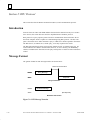
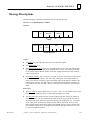
Message Format . . . . . . . . . . . . . . . . . . . . . . . . . . . . . . . . . . . . . . . . . . . . . . . . . . .
7–20
Message Types . . . . . . . . . . . . . . . . . . . . . . . . . . . . . . . . . . . . . . . . . . . . . . . . . . . .
7–21
Message Fields . . . . . . . . . . . . . . . . . . . . . . . . . . . . . . . . . . . . . . . . . . . . . . . . . . . .
7–22
Message Length . . . . . . . . . . . . . . . . . . . . . . . . . . . . . . . . . . . . . . . . . . . . . . . . . . .
7–24
Character Format . . . . . . . . . . . . . . . . . . . . . . . . . . . . . . . . . . . . . . . . . . . . . . . . . .
7–24
Message Termination . . . . . . . . . . . . . . . . . . . . . . . . . . . . . . . . . . . . . . . . . . . . . . .
7–24
Timeout Usage . . . . . . . . . . . . . . . . . . . . . . . . . . . . . . . . . . . . . . . . . . . . . . . . . . . .
7–24
Cyclic Redundancy Check (CRC) . . . . . . . . . . . . . . . . . . . . . . . . . . . . . . . . . . . . .
7–25
Calculating the CRC-16 . . . . . . . . . . . . . . . . . . . . . . . . . . . . . . . . . . . . . . . . . .
7–26
Example CRC-16 Calculation . . . . . . . . . . . . . . . . . . . . . . . . . . . . . . . . . . . . .
7–26
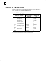
Calculating the Length of Frame . . . . . . . . . . . . . . . . . . . . . . . . . . . . . . . . . . . . . .
7–28
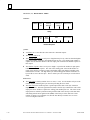
Message Descriptions . . . . . . . . . . . . . . . . . . . . . . . . . . . . . . . . . . . . . . . . . . . . . . .
7–29
Communication Errors . . . . . . . . . . . . . . . . . . . . . . . . . . . . . . . . . . . . . . . . . . .
7–44
Invalid Query Message . . . . . . . . . . . . . . . . . . . . . . . . . . . . . . . . . . . . . . . . . . .
7–44
Serial Link Timeout . . . . . . . . . . . . . . . . . . . . . . . . . . . . . . . . . . . . . . . . . . . . .
7–45
Invalid Transactions . . . . . . . . . . . . . . . . . . . . . . . . . . . . . . . . . . . . . . . . . . . . .
7–46
Section 3: SNP Protocol . . . . . . . . . . . . . . . . . . . . . . . . . . . . . . . . . . . .
x
7–20
7–47
Overview of SNP Protocol . . . . . . . . . . . . . . . . . . . . . . . . . . . . . . . . . . . . . . . . . . .
7–47
SNP Master-Slave Operation . . . . . . . . . . . . . . . . . . . . . . . . . . . . . . . . . . . . . . . . .
7–47
SNP Timers . . . . . . . . . . . . . . . . . . . . . . . . . . . . . . . . . . . . . . . . . . . . . . . . . . . . . .
7–50
SNP Datagrams . . . . . . . . . . . . . . . . . . . . . . . . . . . . . . . . . . . . . . . . . . . . . . . . . . .
7–54
Series 90 PLC Serial Communications User’s Manual – November 2000
GFK-0582D
Contents
Section 4: SNP-X Protocol . . . . . . . . . . . . . . . . . . . . . . . . . . . . . . . . . .
Chapter 8
GFK-0582D
7–57
Overview of SNP-X Protocol . . . . . . . . . . . . . . . . . . . . . . . . . . . . . . . . . . . . . . . . .
7–57
SNP-X Communication Session . . . . . . . . . . . . . . . . . . . . . . . . . . . . . . . . . . . .
7–57
Error Handling . . . . . . . . . . . . . . . . . . . . . . . . . . . . . . . . . . . . . . . . . . . . . . . . .
7–58
Broadcast Capability . . . . . . . . . . . . . . . . . . . . . . . . . . . . . . . . . . . . . . . . . . . .
7–58
Modem Support . . . . . . . . . . . . . . . . . . . . . . . . . . . . . . . . . . . . . . . . . . . . . . . .
7–58
Slave PLC Status Word . . . . . . . . . . . . . . . . . . . . . . . . . . . . . . . . . . . . . . . . . .
7–59
Slave Memory Access Bits (X-Status Bits) . . . . . . . . . . . . . . . . . . . . . . . . . . .
7–59
Timers . . . . . . . . . . . . . . . . . . . . . . . . . . . . . . . . . . . . . . . . . . . . . . . . . . . . . . . .
7–60
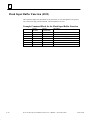
Block Check Code (BCC) . . . . . . . . . . . . . . . . . . . . . . . . . . . . . . . . . . . . . . . .
7–62
SNP-X Protocol Sequence . . . . . . . . . . . . . . . . . . . . . . . . . . . . . . . . . . . . . . . . . . .
7–63
Establish Session . . . . . . . . . . . . . . . . . . . . . . . . . . . . . . . . . . . . . . . . . . . . . . .
7–64
Directed Commands . . . . . . . . . . . . . . . . . . . . . . . . . . . . . . . . . . . . . . . . . . . . .
7–64
Broadcast Commands . . . . . . . . . . . . . . . . . . . . . . . . . . . . . . . . . . . . . . . . . . . .
7–65
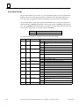
SNP-X Message Structure . . . . . . . . . . . . . . . . . . . . . . . . . . . . . . . . . . . . . . . . . . .
7–67
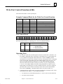
X-Request Message Structure . . . . . . . . . . . . . . . . . . . . . . . . . . . . . . . . . . . . .
7–67
X-Response Message Structure . . . . . . . . . . . . . . . . . . . . . . . . . . . . . . . . . . . .
7–69
X-Buffer Message Structure . . . . . . . . . . . . . . . . . . . . . . . . . . . . . . . . . . . . . . .
7–71
SNP-X Commands . . . . . . . . . . . . . . . . . . . . . . . . . . . . . . . . . . . . . . . . . . . . . . . . .
7–72
X-Attach Command . . . . . . . . . . . . . . . . . . . . . . . . . . . . . . . . . . . . . . . . . . . . .
7–72
X-Read Command . . . . . . . . . . . . . . . . . . . . . . . . . . . . . . . . . . . . . . . . . . . . . .
7–75
X-Write Command . . . . . . . . . . . . . . . . . . . . . . . . . . . . . . . . . . . . . . . . . . . . . .
7–77
SNP-X State Tables . . . . . . . . . . . . . . . . . . . . . . . . . . . . . . . . . . . . . . . . . . . . . . . .
7–84
SNP-X Master State Table . . . . . . . . . . . . . . . . . . . . . . . . . . . . . . . . . . . . . . . .
7–84
SNP-X Master Actions . . . . . . . . . . . . . . . . . . . . . . . . . . . . . . . . . . . . . . . . . . .
7–85
SNP-X Slave State Table . . . . . . . . . . . . . . . . . . . . . . . . . . . . . . . . . . . . . . . . .
7–86
SNP-X Slave Actions . . . . . . . . . . . . . . . . . . . . . . . . . . . . . . . . . . . . . . . . . . . .
7–87
Cable Connection Diagrams . . . . . . . . . . . . . . . . . . . . . . . . . . . . . . . . .
8–1
Section 1: Cable Assembly Specifications . . . . . . . . . . . . . . . . . . . . . .
8–2
Section 2: RS-232 Cable Diagrams . . . . . . . . . . . . . . . . . . . . . . . . . . .
8–3
Section 3: RS-422/RS-485 Cable Diagrams . . . . . . . . . . . . . . . . . . . . .
8–5
RS-422/RS-485 Interface and Cabling Information . . . . . . . . . . . . . . . . . . . . . . .
8–5
RS-422/RS-485 Cable Diagrams . . . . . . . . . . . . . . . . . . . . . . . . . . . . . . . . . . . . . .
8–6
2–Wire and 4–Wire RTU RS422/RS485 Cable Connections . . . . . . . . . . . . .
8–10
2–Wire and 4–Wire RS–422/RS–485 Serial I/O Connections . . . . . . . . . . . .
8–14
Series 90 PLC Serial Communications User’s Manual – November 2000
xi
Contents
Chapter 9
Section 4: IC693CBL316 Serial Cable . . . . . . . . . . . . . . . . . . . . . . . . .
8–16
Section 5: IC690CBL714A MultidropCable . . . . . . . . . . . . . . . . . . . .
8–17
Serial I/O Protocol . . . . . . . . . . . . . . . . . . . . . . . . . . . . . . . . . . . . . . . . . .
9–1
Overview of Serial I/O Protocol Communications . . . . . . . . . . . . . . . . . . . . .
9–2
Serial Communications Sequence of Operations . . . . . . . . . . . . . . . . . . . . . . .
9–3
Format of the Communication Request Function . . . . . . . . . . . . . . . . . . . . . .
9–4
Command Block for the COMMREQ Function . . . . . . . . . . . . . . . . . . . . . . .
9–5
Example of a Serial I/O COMMREQ Instruction . . . . . . . . . . . . . . . . . . . . . .
9–6
Configuring Serial Ports Using the COMMREQ Function . . . . . . . . . . . . . . .
9–8
RTU Slave/SNP Slave Operation With Programmer Attached . . . . . . . . . . . .
9–9
COMMREQ Command Block for Configuring SNP Protocol . . . . . . . . . . . .
9–10
COMMREQ Data Block for Configuring RTU Protocol . . . . . . . . . . . . . . . . .
9–11
COMMREQ Data Block for Configuring Serial I/O Protocol . . . . . . . . . . . . .
9–12
Calling Serial I/O COMMREQs from the PLC Sweep . . . . . . . . . . . . . . . . . .
9–13
Serial I/O COMMREQ Status Word Codes . . . . . . . . . . . . . . . . . . . . . . . . . . .
9–14
Serial I/O COMMREQ Commands . . . . . . . . . . . . . . . . . . . . . . . . . . . . . . . . .
9–16
COMMREQ Overlap Considerations . . . . . . . . . . . . . . . . . . . . . . . . . . . . . . . .
9–17
Initialize Port Function (4300) . . . . . . . . . . . . . . . . . . . . . . . . . . . . . . . . . . . . . . . .
9–18
Set Up Input Buffer Function (4301) . . . . . . . . . . . . . . . . . . . . . . . . . . . . . . . . . . .
9–19
Flush Input buffer Function (4302) . . . . . . . . . . . . . . . . . . . . . . . . . . . . . . . . . . . .
9–20
Read port status Function (4303) . . . . . . . . . . . . . . . . . . . . . . . . . . . . . . . . . . . . . .
9–21
Port Status Words . . . . . . . . . . . . . . . . . . . . . . . . . . . . . . . . . . . . . . . . . . . . . . .
9–22
Write port control Function (4304) . . . . . . . . . . . . . . . . . . . . . . . . . . . . . . . . . . . .
9–23
Cancel COMMREQ Function (4399) . . . . . . . . . . . . . . . . . . . . . . . . . . . . . . . . . .
9–24
Autodial Function (4400) . . . . . . . . . . . . . . . . . . . . . . . . . . . . . . . . . . . . . . . . . . . .
9–25
Autodial Command Block . . . . . . . . . . . . . . . . . . . . . . . . . . . . . . . . . . . . . . . .
9–26
Write bytes Function (4401) . . . . . . . . . . . . . . . . . . . . . . . . . . . . . . . . . . . . . . . . .
9–27
Read bytes Function (4402) . . . . . . . . . . . . . . . . . . . . . . . . . . . . . . . . . . . . . . . . . .
9–28
Return Data Format for the Read Bytes Function . . . . . . . . . . . . . . . . . . . . . .
9–29
Read String Function (4403) . . . . . . . . . . . . . . . . . . . . . . . . . . . . . . . . . . . . . . . . .
9–30
Return Data Format for the Read String Function . . . . . . . . . . . . . . . . . . . . . .
9–31
Appendix A Glossary . . . . . . . . . . . . . . . . . . . . . . . . . . . . . . . . . . . . . . . . . . . . . . . . . .
A–1
Commonly used Acronyms and Abbreviations . . . . . . . . . . . . . . . . . . . . . . . . . . .
A–2
Glossary of Terms . . . . . . . . . . . . . . . . . . . . . . . . . . . . . . . . . . . . . . . . . . . . . . . . .
A–3
xii
Series 90 PLC Serial Communications User’s Manual – November 2000
GFK-0582D
Contents
Appendix B ASCII Code List . . . . . . . . . . . . . . . . . . . . . . . . . . . . . . . . . . . . . . . . . . .
B–1
Appendix C CCM Compatibility . . . . . . . . . . . . . . . . . . . . . . . . . . . . . . . . . . . . . . . .
C–1
Appendix D RTU Compatibility . . . . . . . . . . . . . . . . . . . . . . . . . . . . . . . . . . . . . . . . .
D–1
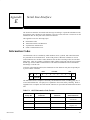
Appendix E Serial Line Interface . . . . . . . . . . . . . . . . . . . . . . . . . . . . . . . . . . . . . . . .
E–1
Information Codes . . . . . . . . . . . . . . . . . . . . . . . . . . . . . . . . . . . . . . . . . . . . . . . . .
E–1
Transmission Errors and Detection . . . . . . . . . . . . . . . . . . . . . . . . . . . . . . . . . . . .
Noise Errors . . . . . . . . . . . . . . . . . . . . . . . . . . . . . . . . . . . . . . . . . . . . . . . . . . .
Transmission Timing Errors . . . . . . . . . . . . . . . . . . . . . . . . . . . . . . . . . . . . . . .
E–2
E–2
E–3
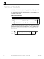
Asynchronous Transmission . . . . . . . . . . . . . . . . . . . . . . . . . . . . . . . . . . . . . . . . .
E–4
Serial Communications Line . . . . . . . . . . . . . . . . . . . . . . . . . . . . . . . . . . . . . . . . .
Modems . . . . . . . . . . . . . . . . . . . . . . . . . . . . . . . . . . . . . . . . . . . . . . . . . . . . . .
E–5
E–5
Interface Standards . . . . . . . . . . . . . . . . . . . . . . . . . . . . . . . . . . . . . . . . . . . . . . . . .
E–6
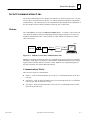
Appendix F Communication Networks . . . . . . . . . . . . . . . . . . . . . . . . . . . . . . . . . . .
F–1
Point-To-Point . . . . . . . . . . . . . . . . . . . . . . . . . . . . . . . . . . . . . . . . . . . . . . . . . . . .
F–1
Multidrop . . . . . . . . . . . . . . . . . . . . . . . . . . . . . . . . . . . . . . . . . . . . . . . . . . . . . . . .
F–2
Modem Transmission . . . . . . . . . . . . . . . . . . . . . . . . . . . . . . . . . . . . . . . . . . . . . .
F–3
Appendix G IC690ACC903 Port Isolator . . . . . . . . . . . . . . . . . . . . . . . . . . . . . . . . .
G–1
Appendix H SNP Multidrop . . . . . . . . . . . . . . . . . . . . . . . . . . . . . . . . . . . . . . . . . . . .
H–1
SNP Multidrop Overview . . . . . . . . . . . . . . . . . . . . . . . . . . . . . . . . . . . . . . . . .
Cable and Connector Specifications . . . . . . . . . . . . . . . . . . . . . . . . . . . . . . . .
SNP Multidrop Examples . . . . . . . . . . . . . . . . . . . . . . . . . . . . . . . . . . . . . . . . .
Configuring and Connecting a Programmer to a Multidrop Network . . . . . . .
SNP Multidrop Troubleshooting . . . . . . . . . . . . . . . . . . . . . . . . . . . . . . . . . . .
H–1
H–2
H–4
H–5
H–6
General Modem Information . . . . . . . . . . . . . . . . . . . . . . . . . . . . . . . . .
I–1
Introduction . . . . . . . . . . . . . . . . . . . . . . . . . . . . . . . . . . . . . . . . . . . . . . . . . . .
Example Modem Application . . . . . . . . . . . . . . . . . . . . . . . . . . . . . . . . . . . . .
..............................................................
Modem Recommendations . . . . . . . . . . . . . . . . . . . . . . . . . . . . . . . . . . . . . . . .
General Modem Issues . . . . . . . . . . . . . . . . . . . . . . . . . . . . . . . . . . . . . . . . . . .
Modem Operating Notes . . . . . . . . . . . . . . . . . . . . . . . . . . . . . . . . . . . . . . . . .
I–1
I–2
I–2
I–3
I–4
I–5
Using Modems with Logicmaster . . . . . . . . . . . . . . . . . . . . . . . . . . . . .
J–1
Introduction . . . . . . . . . . . . . . . . . . . . . . . . . . . . . . . . . . . . . . . . . . . . . . . . . . .
Setting PLC CPU Communications Parameters in Logicmaster . . . . . . . . . . .
Using Logicmaster’s Auto–Dialer Utility . . . . . . . . . . . . . . . . . . . . . . . . . . . .
Using Windows) HyperTerminal . . . . . . . . . . . . . . . . . . . . . . . . . . . . . . . . . . .
J–1
J–2
J–4
J–7
Appendix I
Appendix J
GFK-0582D
Series 90 PLC Serial Communications User’s Manual – November 2000
xiii
Contents
Appendix K Using Modems with VersaPro and Control . . . . . . . . . . . . . . . . . . . . .
K–1
Introduction . . . . . . . . . . . . . . . . . . . . . . . . . . . . . . . . . . . . . . . . . . . . . . . . . . .
K–1
Contents of this Appendix . . . . . . . . . . . . . . . . . . . . . . . . . . . . . . . . . . . . . . . .
K–1
PLC CPU Configuration . . . . . . . . . . . . . . . . . . . . . . . . . . . . . . . . . . . . . . . . . .
K–2
Installing a Modem in Windows . . . . . . . . . . . . . . . . . . . . . . . . . . . . . . . . . . .
K–3
Setting Up the Communications Configuration Utility (CCU) . . . . . . . . . . . .
K–6
Connecting to the PLC . . . . . . . . . . . . . . . . . . . . . . . . . . . . . . . . . . . . . . . . . . .
K–9
Using HyperTerminal to Establish Connection . . . . . . . . . . . . . . . . . . . . . . . .
K–10
Appendix L Getting Help . . . . . . . . . . . . . . . . . . . . . . . . . . . . . . . . . . . . . . . . . . . . . .
L–1
Getting Additional Help and Information . . . . . . . . . . . . . . . . . . . . . . . . . . . .
L–1
Series 90 Product Repair . . . . . . . . . . . . . . . . . . . . . . . . . . . . . . . . . . . . . . . . .
L–2
Modem Support . . . . . . . . . . . . . . . . . . . . . . . . . . . . . . . . . . . . . . . . . . . . . . . .
L–2
EIA Standards . . . . . . . . . . . . . . . . . . . . . . . . . . . . . . . . . . . . . . . . . . . . . . . . . .
L–2
Appendix M Series 90 Micro PLC Serial Ports . . . . . . . . . . . . . . . . . . . . . . . . . . . . .
M–1
Appendix N IC655CMM590 Isolated Repeater/Converter . . . . . . . . . . . . . . . . . . .
N–1
Description of the Isolated Repeater/Converter . . . . . . . . . . . . . . . . . . . . . . . . . .
N–1
System Configurations . . . . . . . . . . . . . . . . . . . . . . . . . . . . . . . . . . . . . . . . . . . . . .
N–5
Cable Diagrams for IC655CMM590 Converter . . . . . . . . . . . . . . . . . . . . . . . . . .
N–7
Appendix O IC690ACC901 Miniconverter and Cable Kit . . . . . . . . . . . . . . . . . . . .
O–1
xiv
Series 90 PLC Serial Communications User’s Manual – November 2000
GFK-0582D
restart lowapp ARestart oddapp: ARestarts for autonumbers that do not restart in each
chapter. figure bi level 1, reset table_big level 1, reset chap_big level 1, reset1 Lowapp
Alwbox restart evenap:A1app_big level 1, resetA figure_ap level 1, reset table_ap level
1, reset figure level 1, reset Figure 1. table level 1, reset Table 1. these restarts oddbox
reset: 1evenbox reset: 1must be in the header frame of chapter 1. a:ebx, l 1 resetA a:obx:l
1, resetA a:bigbx level 1 resetA a:ftr level 1 resetA c:ebx, l 1 reset1 c:obx:l 1, reset1
c:bigbx level 1 reset1 c:ftr level 1 reset1 Reminders for autonumbers that need to be
restarted manually (first instance will always be 4) let_in level 1: A. B. C. letter level
1:A.B.C. num level 1: 1. 2. 3. num_in level 1: 1. 2. 3. rom_in level 1: I. II. III. roman
level 1: I. II. III. steps level 1: 1. 2. 3.
Chapter
1 Introduction
1
This chapter includes a quick reference to the manual and provides a summary of the serial
communications capabilities of the Series 90 products.
Quick Guide to the Manual
The purpose of this manual is to describe how to use the serial communications features of the
Series 90 Communications Coprocessor Modules (CMMs) and CPUs. Hardware topics include
installing the modules and constructing and installing the serial communications cables. Software
topics include configuring the modules using GE Fanuc PLC Software and programming serial
communications requests (COMMREQs) in ladder diagrams.
Topics
Communications Capabilities Table and
protocol overview
Where to go in the Manual
Chapter 1:
Introduction
- The Communications Coprocessor
Module (CMM)
Chapter 2:
The CMM - Description,
Installation, and Configuration
- Description of Series 90 CPU Serial Ports
Chapter 3:
Series 90 CPU Serial Ports
- Communications Cables,
Isolated Repeater/Converter,
Miniconverter
Port Isolator
Chapter 8:
Serial cables, isolators, and converters
- Modems
Appendix I,
J, and K:
Modem basics, setting modem parameters
Chapter 2:
CMM Configuration
Chapter 3:
CPU Configuration
Chapter 4:
Initiating Communications The COMMREQ
Chapter 5:
CCM Service
Chapter 6:
SNP Service
- Protocol Descriptions
Chapter 7:
Protocol Definition - CCM, RTU, SNP,
SNP-X
- Serial I/O Protocol
Chapter 9:
Protocol definition, programming example
Hardware
Software
- Module Configuration
- Ladder Programming (COMMREQ)
GFK-0582D
1–1
1
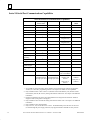
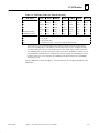
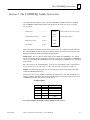
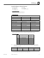
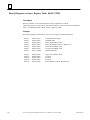
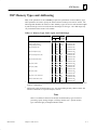
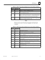
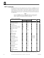
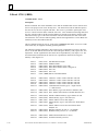
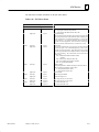
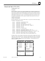
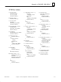
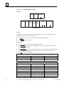
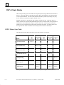
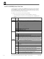
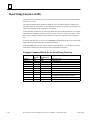
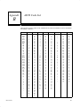
Series 90 Serial Port Communications Capabilities
Series 90 Serial Port Communications Capabilities
Protocol or Feature
Series 90–30 CPU
Ports 1 and 26
Series 90–70 CPUs
Series 90 PCMs
Series 90
CMMs
SNP (slave)
Yes
Yes
Yes3 (with C file)
Yes
SNP (master)
Yes1
No
Yes3 (with C file)
Yes
Break–Free SNP
Yes1
Yes1
No
No
SNP–X (slave)
Yes
SNP–X (master)
No
RTU (slave)
Yes2
No
Yes3
(with C file)
Yes
No
Yes3
(with C file)
Yes
Yes3 (with
No
Yes
Megabasic file)
RTU (master)
No
No
Yes3 (with
Megabasic file)
No
CCM (slave)
No
No
Yes
Yes
CCM (master &
peer)
No
No
Yes
Yes
Serial I/O Read
Yes4
No
No
No
Serial I/O Write
Yes2
No
No
No
MegaBasic programming
No
No
Yes
No
C programming
Yes5
Yes
Yes
No
Datagrams
Yes1
Yes
C programmer
“printf” support
No
Yes1
Yes
No
C–Debugger support
No
Yes1
No
No
Port 1
Port 1
All ports except for
Port 2 of PCM300
All ports
Ports 2 and 3, and
Standard SNP port
on single port CPUs
Ports 2 and 3, and
Standard SNP port
on single port CPUs
Port 2 of PCM300,
PCM301, and
PCM311
Port 2 of
CMM311
RS–232
RS–422/485
Yes3
(with C file)
Both ports of
PCM711
1
2
3
4
5
6
1–2
Yes
Both ports of
CMM711
Not available for all CPU firmware releases and may not be supported by all releases of Logicmaster,
VersaPro, or Control PLC programming software. See Chapter 3 for details on CPU capabilities.
Only available on Ports 1 and 2 of CPUs 351 (firmware release 8.00 and later), 352 (firmware release
8.00 and later), and 363 (all versions), starting with firmware release 8.00. See Chapter 3 for additional
information.
Requires an application file, which can be downloaded free of charge from the GE Fanuc Technical
Support web site (www.gefanuc.com/support).
Only available on CPUs 352 and 363 starting with firmware release 10.00. See Chapter 3 for additional
information.
Only available on CPUs 350 and higher.
Only CPUs 351, 352, and 363 have Ports 1 and 2. The Standard SNP port on all Series 90–30 CPUs
(accessed through the power supply connector) only supports SNP slave and SNP–X slave protocols.
Series 90 PLC Serial Communications User’s Manual – November 2000
GFK-0582D
Introduction
1
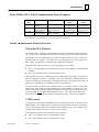
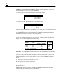
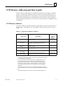
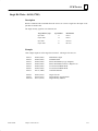
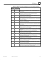
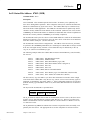
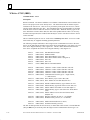
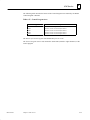
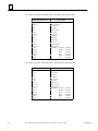
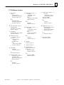
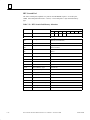
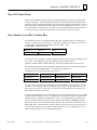
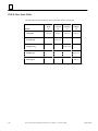
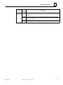
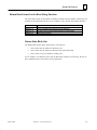
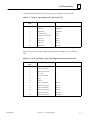
Series 90 Micro PLC Serial Communications Protocol Support
Micro
PLCs
14–point
23–point
28–point
SNP/SNPX Slave
SNP/SNPX Master*
Port 1
All releases
Ports 1 and 2,
Rel. 3.00 and later
Ports 1 and 2,
Rel. 2.01 and later
not supported
Port 2
Rel. 3.00 and later
Port 2
Rel. 3.00 and later
4–Wire RTU
Slave*
Port 1
Rel. 3.00 and later
Port 2
Rel. 3.00 and later
Port 2
Rel. 3.00 and later
2–Wire RTU
Slave*
Port 1
Rel. 3.10 and later
Port 2
Rel. 3.10 and later
Port 2
Rel. 3.10 and later
*Also requires the following versions or later hardware: IC693UDR001LP1, IC693UDR002LP1, IC693UAA003JP1,
IC693UDR005JP1, IC693UAL006BP1, IC693UAA007HP1, and IC693UDR010BP1.
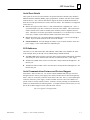
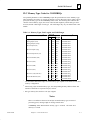
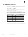
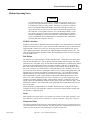
Serial Communications Protocol Overview
SNP and SNP-X Protocols
The SNP protocol is a proprietary communications protocol developed by GE Fanuc Automation. It is the native communications protocol for all models of the Series 90 PLC product line.
The SNP-X protocol is a highly optimized extension of SNP. While it offers fewer functions
than SNP, SNP-X is simpler to use and provides a significant performance improvement over
SNP. It does not support PLC programming or configuration operations.
The SNP and SNP-X protocol allows for the following types of operation:
D
Master - the initiating device in a Master/Slave system (only available on CMM and PCM
modules).
D
Slave - the responding device in a Master/Slave system.
The SNP master and slave as implemented on the CMM module do not support PLC programming or configuration functions. Logicmaster 90 may be connected to a CMM serial port configured as an SNP slave for data display and modification only. (The SNP-X protocol does not
support PLC programming or configuration under any circumstances.)
The SNP and SNP-X protocols can be enabled on none, one, or both serial ports of the CMM
module using either the RS-232 or RS-422/RS-485 electrical standard. Essentially, any combination of protocols, ports, and electrical standards are available with one exception: The Series 90-30 CMM cannot support RS-422/RS-485 on port 1. Port selection, data rate, parity,
flow control, number of stop bits, timeouts, and turnaround delay values can be configured.
CCM Protocol
CCM protocol is included in the EPROM firmware for both the Series 90-70 and Series 90-30
CMM modules. The CCM protocol was originally developed for the Series Six Communications Control Module (CCM) and is available on most GE Fanuc PLCs. It is available on the
CMM and PCM modules, but not on Series 90 CPU serial ports.
The CCM protocol allows for the following types of operation:
GFK-0582D
D
Master - the initiating device in a Master/Slave system.
D
Slave - the responding device in a Master/Slave system.
Chapter 1 Introduction
1–3
1
D
Peer - initiates and responds to another Peer device.
The CCM protocol can be enabled on none, one, or both of the serial ports of the CMM module
using either the RS-232 or RS-422/RS-485 electrical standard. Essentially, any combination of
protocols, ports, and electrical standards are available with one exception: The Series 90-30
CMM cannot support RS-422/RS-485 on port 1. Port selection, data rate, parity, flow control,
timeouts, turnaround delay, station address/CPU ID, and retry values can be configured.
RTU Protocol
RTU protocol is available on the Series 90-30 CPU ports, 351, 352 and 363 serial ports, and the
Series 90-70 and Series 90-30 CMM modules. RTU protocol as implemented on the CMM is a
subset of the ModbustRemote Terminal Unit (RTU) serial communications protocol.
RTU is a half–duplex protocol. It is commonly wired in either of two configurations: 2–Wire
or 4–Wire. For details on this subject, please refer to the section “2–Wire and 4–Wire RTU” in
Chapter 7.
The RTU protocol as implemented on the CMMs and CPUs provides for Slave operation only.
However, a MegaBasic application file is available that enables a PCM module to support the
RTU Master or Slave implementation. This file is available for free download from the GE
Fanuc Technical Support site. See Appendix G, “Getting Help,” for information on the GE Fanuc web site.
D
Master - the initiating device in a Master/Slave system.
D
Slave - the responding device in a Master/Slave system.
The RTU protocol can be enabled on none, one, or both of the serial ports of the CMM module,
on several CPU serial ports, and on PCM serial ports (using the MegaBasic application file)
using either the RS-232 or RS-422/RS-485 electrical standard. Essentially, any combination of
protocols, ports, and electrical standards are available with one exception: The Series 90-30
CMM cannot support RS-422/RS-485 on port 1. Port selection, station address, data rates,
flow control, and parity values can be configured.
Additional RTU Solutions
D
Horner Electric makes RTU master modules for the Series 90–30 (HE693RTM705) and
Series 90–70 (HE697RTM700) PLCs. Contact your GE Fanuc distributor or Horner Electric (see Chapter L for information).
D
The Series 90 PCM modules can serve as an RTU master by using the MegaBasic application file that can be downloaded free of charge from the GE Fanuc Technical Support web
site (www.gefanuc.com/support).
tModbus is a trademark of Gould, Inc.
1–4
Series 90 PLC Serial Communications User’s Manual – November 2000
GFK-0582D
Chapter
2 The Communications Coprocessor Modules
2
section level 1 1
figure bi level 1
table_big level 1
This chapter describes the Communications Coprocessor modules (CMM311, CMM711) and
explains how to install and configure the modules. Also included is a discussion of the system
operation of the modules in the Series 90 PLC:
The chapter is divided into two sections.
D
Section 1: Description of CMM Hardware and Operation
D
Section 2: Installing and Configuring the CMM
Overview of the CMM
The Communications Coprocessor Module (CMM) is a high-performance microcomputer designed to perform communications functions in a Series 90 PLC system.
The CMM is closely coupled to the Series 90 PLC and may be configured to behave as two
independent communications ports. For many applications, each port behaves like an independent window into the PLC for access by other devices, such as industrial computers and color
graphic terminals. Many applications, which accessed the Series Six PLC user reference tables
using CCM or RTU protocols, can now support the Series 90 PLC with little or no change.
Many applications, which access the Series 90 PLC via the built-in serial port on the PLC CPU
using SNP protocol, can now access the PLC via the CMM module.
Each CMM occupies a single slot in a Series 90 PLC rack. Up to 28 CMMs may be installed
in a single Series 90-70 PLC system to improve access to serial I/O devices and to access PLC
memory. In Series 90-30 PLCs, up to 4 CMMs may be installed in the main rack (baseplate).
GFK-0582D
2–1
2
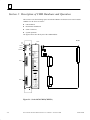
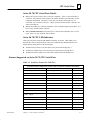
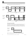
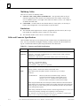
Section 1: Description of CMM Hardware and Operation
This section covers the following topics for both the CMM711 for the Series 90-70 PLC and the
CMM311 for the Series 90-30 PLC.
D
LED Indicators
D
Restart/Reset Pushbutton
D
Serial Connectors
D
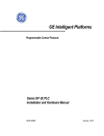
System Operation
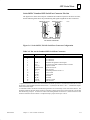
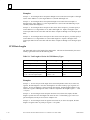
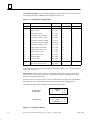
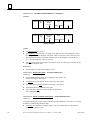
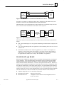
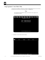
The figures below show the layout of the CMM modules:
a44901
ÎÎÎ
ÎÎ
Î
ÎÎÎ
ÎÎ
Î
ÎÎ
Î
ÎÎ
Î
ÎÎ
ÎÎ
Î
ÎÎ
Î
ÎÎ
Î
ÎÎ
Î
ÎÎ
Î
ÎÎ
Î
ÎÎ
Î
ÎÎ
Î
ÎÎ
Î
ÎÎ
Î
ÎÎ
Î
ÎÎ
Î
ÎÎ
Î
ÎÎ
Î
ÎÎ
ÎÎ
ÎÎ Î
ÎÎ
Î
DOOR
BD
OK
PORT 1
PORT 2
RESTART
MODEL 70
CMM 711
MODULE OK
PORT 1
PORT 2
ON = OK, ACTIVE
BLINK =
COMMUNICATING
PUSH TO RESTART
APPLICATION
PORT 1
PORT 1
RS–232 OR
RS–422
COMPATIBLE
PORT 2
RS–232 OR
ÎÎ
ÎÎ
ÎÎ
ÎÎ
RS–422/485
COMPATIBLE
MODULE FUNCTION
PORT 2
SERIES 90–70
COMMUNICA TIONS
COPROCESSOR
PORT 1 & 2 RS–232
PIN SIGNAL
1
SHIELD
2
TD
3
RD
4
RTS
5
CTS
7
GROUND
8
DCD *
20 DTR *
PORT 1 & 2 RS–422
PIN SIGNAL
7
GROUND
SD (A)
9
10 RTS (A) *
CTS (A) *
11
12 TERM PIN 11 *
13 RD (A)
21 SD (B)
22 RTS (B) *
23 CTS (B) *
24 TERM PIN 25 *
25 RD (B)
*CONFIGURA TION
DEPENDENT
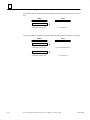
MODULE IC697CMM711
LABEL 44A726758–124R01
ÎÎ
ÎÎ
ÎÎ
ÎÎ
Figure 2-1. Series 90-70 CMM (CMM711)
2–2
Series 90 PLC Serial Communications User’s Manual – November 2000
GFK-0582D
CCM Modules
COMM
COPROC
OK
US1
US2
OK
US1
US2
Î
Î
2
a44902
RESTART
COMBINED
SERIAL PORT
PORT1
&
PORT2
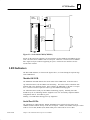
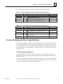
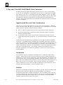
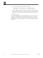
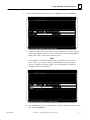
Figure 2-2. Series 90-30 CMM (CMM311)
Except for the serial port connectors, the user interfaces for the CMM311 and CMM711 are the
same. The Series 90-70 CMM711 has two serial port connectors. The Series 90-30 CMM311
has a single serial port connector supporting two ports. Each of the user interfaces are discussed below in detail.
LED Indicators
The three LED indicators, as shown in the figures above, are located along the top front edge
of the CMM board.
Module OK LED
The MODULE OK LED indicates the current status of the CMM board. It has three states:
Off: When the LED is off, the CMM is not functioning. This is the result of a hardware malfunction (that is, the diagnostic checks detect a failure, the CMM fails, or the PLC is not present). Corrective action is required in order to get the CMM functioning again.
On: When the LED is steady on, the CMM is functioning properly. Normally, this LED
should always be on, indicating that the diagnostic tests were successfully completed and the
configuration data for the module is good.
Flashing: The LED flashes during power-up diagnostics.
Serial Port LEDs
The remaining two LED indicators, PORT1 and PORT2 (US1 and US2 for the Series 90-30
CMM311) blink to indicate activity on the two serial ports. PORT1 (US1) blinks when port 1 either
sends or receives data; PORT2 (US2) blinks when port 2 either sends or receives data.
GFK-0582D
Chapter 2 The Communications Coprocessor Modules
2–3
2
Restart/Reset Pushbutton
If the Restart/Reset pushbutton is pressed when the MODULE OK LED is on, the CMM will
be re-initialized from the Soft Switch Data settings.
If the MODULE OK LED is off (hardware malfunction), the Restart/Reset pushbutton is inoperative; power must be cycled to the entire PLC for CMM operation to resume.
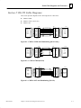
Serial Ports
The serial ports on the CMM are used to communicate with external devices. The Series 90-70
CMM (CMM711) has two serial ports, with a connector for each port. The Series 90-30 CMM
(CMM311) has two serial ports, but only one connector. The serial ports and connectors for
each PLC are discussed below.
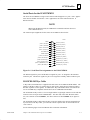
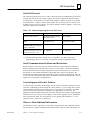
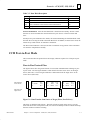
Serial Ports for the CMM711
The Series 90-70 CMM has two serial ports, each of which support both RS-232 and RS-485
modes. The pin assignments of the serial ports are identical.
Note
When using the RS-485 mode, the CMM can be connected to RS-422 devices as
well as RS-485 devices.
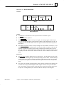
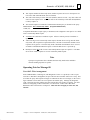
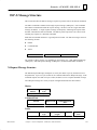
The connector pin assignments for both ports of the Series 90-70 CMM are shown below:
SHIELD
RS-232 TD
RS-232 RD
RS-232 RTS
RS-232 CTS
NO CONNECTION
SIGNAL GROUND
RS-232 DCD
RS-485 SD ( A )
RS-485 RTS ( A )
RS-485 CTS ( A’ )
TERMINATION ( CTS )
RS-485 RD ( A’ )
ÎÎ
Î
ÎÎ
Î
ÎÎ
Î
ÎÎ
Î
ÎÎ
Î
ÎÎ
Î
ÎÎ
ÎÎ
Î
ÎÎ
ÎÎ
ÎÎ
a42734
1
14
RESERVED
15
RESERVED
16
RESERVED
17
RESERVED
18
RESERVED
19
RESERVED
20
RS-232 DTR
21
RS-485 SD ( B )
22
RS-485 RTS ( B )
23
RS-485 CTS ( B’ )
24
TERMINATION ( RD )
25
RS-485 RD ( B’ )
2
3
4
5
6
7
8
9
10
11
12
13
Figure 2-3. Serial Port Pin Assignments for the Series 90-70 CMM
Note
In the figure above, SD (Send Data) and RD (Receive Data) are the same as TXD
and RXD (used in the Series SixTM PLC). (A) and (B) are the same as – and +.
A’ and B’ denote inputs, and A and B denote outputs. To terminate the RS-485
CTS input signal, jumper pins 11 and 12; to terminate the RD input signal, jumper pins 24 and 25.
2–4
Series 90 PLC Serial Communications User’s Manual – November 2000
GFK-0582D
CCM Modules
2
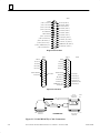
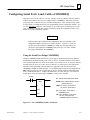
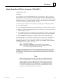
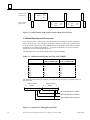
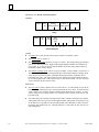
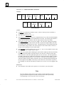
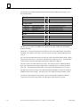
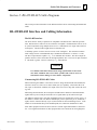
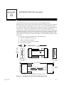
Serial Ports for the IC693CMM311
The Series 90-30 CMM has a single serial connector which supports two ports. Port 1 applications must use the RS-232 interface. Port 2 applications can select either the RS-232 or
RS-485 interface.
NOTE
When using the RS-485 mode, the CMM can be connected to RS-422 devices as
well as RS-485 devices.
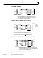
The connector pin assignments for the Series 90-30 CMM are shown below.
SHIELD
( PORT 1 ) RS-232 TD
( PORT 1 ) RS-232 RD
( PORT 1 ) RS-232 RTS
( PORT 1 ) RS-232 CTS
NO CONNECTION
SIGNAL GROUND
( PORT 1 ) RS-232 DCD
( PORT 2 ) RS-485 SD ( A )
( PORT 2 ) RS-485 RTS ( A )
( PORT 2 ) RS-485 CTS ( A’ )
( PORT 2 ) TERMINATION ( CTS )
( PORT 2) RS-485 RD ( A’ )
Î
Î
ÎÎ
Î
ÎÎ
Î
ÎÎ
Î
ÎÎ
Î
ÎÎ
Î
ÎÎ
Î
ÎÎ
ÎÎ
ÎÎ
ÎÎ
ÎÎÎ
ÎÎ
ÎÎÎ
a44357
1
14
RS-232 TD ( PORT 2 )
15
RS-232 CTS ( PORT 2 )
16
RS-232 RD ( PORT 2 )
17
RS-232 DTR ( PORT 2 )
18
RS-232 DCD ( PORT 2 )
19
RS-232 RTS ( PORT 2 )
20
RS-232 DTR ( PORT 1 )
21
RS-485 SD ( B ) (PORT 2 )
22
RS-485 RTS ( B ) ( PORT 2 )
23
RS-485 CTS ( B’ ) ( PORT 2 )
24
TERMINATION ( RD ) (PORT 2)
25
RS-485 RD ( B’ ) ( PORT 2 )
2
3
4
5
6
7
8
9
10
11
12
13
Figure 2-4. Serial Port Pin Assignments for the IC693CMM311
The RS-485 signals for port 2 and the RS-232 signals for port 1 are assigned to the standard
connector pins. The RS-232 signals for port 2 are assigned to normally unused connector pins.
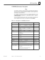
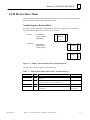
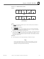
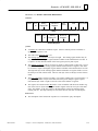
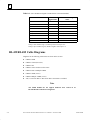
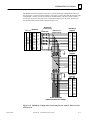
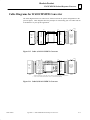
IC693CBL305 Wye Cable
A Wye cable (IC693CBL305) is supplied with each Series 90-30 CMM and PCM module. The
purpose of the Wye cable is to separate the two ports from a single physical connector (that is,
the cable separates out the signals). In addition, the Wye cable makes cables used with the Series 90-70 CMM fully compatible with the Series 90-30 CMM and PCM modules.
The IC693CBL305 Wye cable is 1 foot in length and has a right angle connector on the end that
connects to the serial port on the CMM module. The other end of the cable has dual connectors; one connector is labeled PORT 1, the other connector is labeled PORT 2 (see figure below).
The IC693CBL305 Wye cable routes the Port 2, RS-232 signals to the RS-232 designated pins.
If you do not use the Wye cable, you will need to make a special cable to connect RS-232 devices to Port 2.
See the following figure for IC693CBL305 cable connection information.
GFK-0582D
Chapter 2 The Communications Coprocessor Modules
2–5
2
ÎÎ
ÎÎ
Î
Î
ÎÎ
Î
ÎÎ
Î
ÎÎ
Î
ÎÎ
Î
ÎÎ
Î
ÎÎ
Î
ÎÎ
Î
ÎÎ
Î
ÎÎ
Î
SHIELD
a44357
1
( PORT 1 ) RS-232 TD
14
RS-232 TD ( PORT 2 )
15
RS-232 CTS ( PORT 2 )
16
RS-232 RD ( PORT 2 )
17
RS-232 DTR ( PORT 2 )
18
RS-232 DCD ( PORT 2 )
19
RS-232 RTS ( PORT 2 )
20
RS-232 DTR ( PORT 1 )
21
RS-485 SD ( B ) (PORT 2 )
22
RS-485 RTS ( B ) ( PORT 2 )
23
RS-485 CTS ( B’ ) ( PORT 2 )
24
TERMINATION ( RD ) (PORT 2)
25
RS-485 RD ( B’ ) ( PORT 2 )
2
( PORT 1 ) RS-232 RD
3
( PORT 1 ) RS-232 RTS
4
( PORT 1 ) RS-232 CTS
5
NO CONNECTION
6
SIGNAL GROUND
7
( PORT 1 ) RS-232 DCD
8
( PORT 2 ) RS-485 SD ( A )
9
( PORT 2 ) RS-485 RTS ( A )
10
( PORT 2 ) RS-485 CTS ( A’ )
11
( PORT 2 ) TERMINATION ( CTS )
12
( PORT 2) RS-485 RD ( A’ )
13
Single Connector End
ÎÎÎ
ÎÎÎ
ÎÎ
ÎÎ
ÎÎ
ÎÎ
ÎÎÎ
ÎÎÎ
ÎÎ
ÎÎ
ÎÎ
ÎÎ
ÎÎÎ
ÎÎÎ
ÎÎ
ÎÎ
ÎÎ
ÎÎ
ÎÎÎ
ÎÎ
ÎÎ
ÎÎÎ
ÎÎÎ
ÎÎ
ÎÎ
ÎÎÎ
ÎÎ
ÎÎ
ÎÎ
ÎÎ
ÎÎÎ
ÎÎÎ
ÎÎ
ÎÎ
PORT 1
SHIELD
PORT 2
1
RS-232 TD
2
RS-232 RD
3
RS-232 RTS
4
14
RS-232 TD
15
3
16
RS-232 RTS
16
4
17
RS-232 CTS
17
RS-232 CTS
5
18
6
19
RS-232 DCD
19
7
20
8
SIGNAL GROUND
7
RS-232 DCD
8
RS-232 DTR
21
9
RS-485 SD ( A )
22
RS-485 RTS ( A )
10
23
RS-485 CTS ( A’)
11
24
12
13
PIN 1
RS-232
25-PIN MALE
CONNECTOR
1 FOOT
(+2.0 INCH, -0 INCH)
LABEL
PCM COMM. CABLE
IC693CBL305B
RS-485 SD ( B )
22
RS-485 RTS ( B )
23
RS-485 CTS ( B’ )
24
TERMINATION ( RD )
25
RS-485 RD ( B’ )
11
RS-485 RD ( A’)
Wye Connector End
RS-232 DTR
21
10
12
25
20
9
TERMINATION ( CTS )
13
Î
5
18
6
SIGNAL GROUND
a44358
14
2
15
RS-232 RD
ÎÎÎÎ
ÎÎÎ
ÎÎÎ
Î
ÎÎ
Î
ÎÎ
ÎÎÎ
Î
ÎÎ
Î
ÎÎ
Î
ÎÎ
Î
ÎÎ
Î
ÎÎ
Î
ÎÎ
ÎÎ
Î
Î
ÎÎ
ÎÎ
Î
SHIELD
1
Î
Î
Î
IC693CBL305
RS-232
25-PIN FEMALE
CONNECTOR
a44225
PIN 1
PORT 1
PORT 2
RS-232/RS-485
25-PIN FEMALE
CONNECTOR
PIN 1
Figure 2-5. IC693CBL305 Wye Cable Connections
2–6
Series 90 PLC Serial Communications User’s Manual – November 2000
GFK-0582D
CCM Modules
2
Section 2: Installing and Configuring the CMM
This section explains how to install the CMM in the rack (Series 90-70) or baseplate (Series
90-30) and how to configure the module using Logicmaster 90 or the windows-based programming software. Topics covered are:
D
What you will Need
D
Installing the CMM
D
Configuring the CMM
What you will Need
Before you can begin the installation procedure, you must have the following equipment and
software packages:
D
A Series 90-70 or Series 90-30 Programmable Logic Controller (PLC).
(For Series 90-30, the CPU must be a model CPU331 or higher.)
D
A Communications Coprocessor Module (CMM) to install and test:
-
IC697CMM711 for a Series 90-70 CMM
-
IC693CMM311 for a Series 90-30 CMM
If this application uses CCM protocol with standard default settings for a Series 90-30 CMM
(CMM 311), no other equipment is required.
For other applications, you will also need the following:
GFK-0582D
D
A computer with a hard disk.
D
Programming software (either Logicmaster 90 or windows-based programming software).
Chapter 2 The Communications Coprocessor Modules
2–7
2
Installing the CMM Hardware
The first step in the installation procedure is to physically install the CMM hardware and verify
that it is working properly.
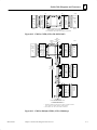
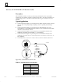
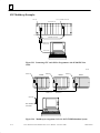
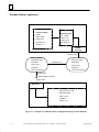
Overview
In a single rack system, the CMM resides in the same rack as the CPU. In a Series 90-70 multiple rack system, the CMM can reside in either the CPU rack or in an expansion rack. The
Series 90-30 CMM must reside in the same rack as the CPU.
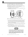
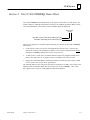
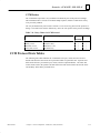
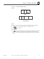
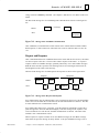
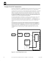
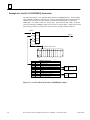
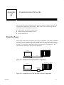
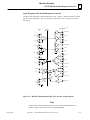
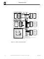
The following illustration shows one possible system configuration for installing a Series 90-70
CMM in a local or expansion rack:
ÎÎÎÎ
ÎÎ
ÎÎÎÎ
ÎÎÎ
ÎÎ
Î
ÎÎ
Î
ÎÎ
ÎÎ
Î
ÎÎ
Î
ÎÎ
Î
ÎÎ
ÎÎ
ÎÎ
ÎÎÎÎ
ÎÎÎ
ÎÎ
Î
ÎÎÎ
ÎÎÎÎ
ÎÎ
ÎÎÎÎ
ÎÎÎ
ÎÎ
Î
ÎÎÎÎ
ÎÎ
ÎÎÎÎ
ÎÎÎ
ÎÎ
Î
ÎÎ
ÎÎ
ÎÎ
ÎÎ
Î
Î
ÎÎ
ÎÎ
Î
ÎÎ
ÎÎ
Î
ÎÎ
ÎÎ
Î
ÎÎ
Î
ÎÎ
ÎÎ
Î
ÎÎ
ÎÎÎÎÎ
ÎÎ
ÎÎ
ÎÎ
ÎÎ
Î
Î
ÎÎ
ÎÎ
Î
ÎÎ
Î
ÎÎ
Î
ÎÎ
Î
ÎÎ
ÎÎ
Î
ÎÎ
ÎÎ
ÎÎ
ÎÎ
Î
Î
ÎÎ
ÎÎ
Î
ÎÎ
ÎÎ
Î
ÎÎ
ÎÎ
Î
ÎÎ
Î
ÎÎ
ÎÎ
Î
ÎÎ
ÎÎÎÎ
ÎÎÎÎ
Î
ÎÎÎÎÎ
Î ÎÎÎÎ
ÎÎÎÎÎ
ÎÎÎ
ÎÎÎ
Î
ÎÎ
ÎÎÎÎ
ÎÎÎÎ
Î
ÎÎÎÎÎ
Î ÎÎÎÎ
ÎÎÎÎÎ
ÎÎÎ
ÎÎÎ
Î
LOCAL RACK CONFIGURATION
P
S
C C
P M
U M
CPU RACK
P
S
a44915
C B
P T
U M
EXPANSION RACK
P
S
B C
R M
M M
Figure 2-6. Series 90-70 CMM Configurations
The power supply, CPU, and Series 90-70 Bus Expansion Module must reside in specific slots
within the rack. The term Bus Expansion Module includes both Bus Transmitter Modules and
Bus Receiver Modules. The CPU Module must be located in slot 1 of rack 0.
The Series 90-70 system usually includes a Bus Transmitter Module (BTM). Version A of the
Bus Transmitter Module must be located to the right of all other GE Fanuc boards; version B
must be located in slot 2 of rack 0. If the PLC system will have more than one rack, a Bus Receiver Module (BRM) must be located in slot 1 of each expansion rack.
The CMM can be placed in any slot not already allocated in any rack, with the following cautions:
2–8
D
The configuration files created by the Logicmaster 90 configuration software must match
the physical configuration of the modules. If they do not, the controller may not operate as
expected. Any faults will be logged in the PLC fault table.
D
When CMMs are in a Series 90-70 rack, all the slots between the CMM and the PLC CPU
must be occupied. If any of these slots are empty, the CMM will not be able to communicate across the backplane to the Series 90-70 PLC CPU.
D
The Series 90-30 CMM must be in the main rack (baseplate) with the PLC CPU.
Series 90 PLC Serial Communications User’s Manual – November 2000
GFK-0582D
CCM Modules
2
Installing the CMM in the Rack
To install the CMM in the rack, follow these steps:
1.
Set the PLC CPU to STOP. This will prevent the local PLC application program, if any,
from initiating any command that may affect the operation of the module.
2.
Power down the Series 90 PLC system.
3.
Locate the desired rack and slot.
4.
Slide the CMM completely into the slot. The three LEDs will be at the top of the board.
5.
Press down firmly to lock the board in place, but do not use excessive force.
6.
Power up the PLC rack. The top LED (MODULE OK) of the Series 90-70 CMM will flash
during power-up diagnostics. It continues to flash while waiting for configuration data
from the CPU. If no signal is received across the backplane for 30 seconds, the Series
90-70 CMM will assume the CPU is not there and continue to power up without it. Once
the CMM is ready, this LED should stop flashing and remain ON.
Note
The top LED (MODULE OK) of the Series 90-30 CMM will not light if the PLC
is not present, or if the CMM fails its power-up diagnostics.
7.
Repeat this procedure for each CMM.
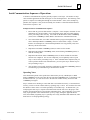
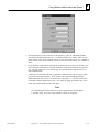
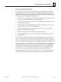
Troubleshooting
After completing the above steps to install the CMM, the MODULE OK (BD OK) LED
should be on continuously. If it is not, the problem may be either that the LED is burned out,
or the board has not passed diagnostics. Follow this procedure to determine the cause of the
problem:
GFK-0582D
1.
Make sure that power to the rack is on, the PLC is okay, and that the CMM is seated properly.
2.
Check the PLC fault table using the programming software. If there is a bad or missing
module fault, the board may be defective; otherwise, contact the GE Fanuc Technical Support Hotline for assistance. The GE Fanuc PLC Technical Support Hotline can be reached
at 1-800-GE FANUC (1-800-433-2682), or International direct dial 804-978-6036.
3.
Change the CMM config to SNP (RS-232 is needed), and run the programming software
through the CMM using either the IC690CBL702 (9-pin AT) or IC690CBL705 (25-pin
PS-2) cable.
Chapter 2 The Communications Coprocessor Modules
2–9
2
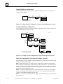
Configuring the CMM
Configuring the CMM through the programming software is a two-part procedure:
D
I/O Rack Configuration
D
Module Configuration (Soft Switch Data)
I/O Rack Configuration
The Series 90 I/O Rack Configuration software is used to define the type and location of all
modules present in the PLC racks. This is done by completing setup screens which represent
the modules in a rack. Specific configuration settings for individual modules can then be selected. The configuration data is saved in a configuration file which is then stored to the Series
90 PLC.
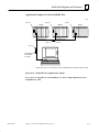
Series 90-70 PLCs
A rack in the Series 90-70 PLC can be used as a main CPU rack or as an expansion rack.
Racks are available that have either 5 or 9 slots for modules, plus provision for a power supply
or power supply connection in the leftmost slot. The rack shown in the previous illustration has
9 slots for modules.
The rack in which the CPU resides requires a power supply in slot PS and a CPU module in
slot 1. Slot 1 in the CPU rack is reserved for the CPU module; in an expansion rack, slot 1 is
reserved for the Bus Receiver Module (BRM). A Bus Transmitter Module must be installed in
slot 2 of rack 0 if it is a version B (or later) module; version A of the BTM must be located to
the right of all other GE Fanuc boards. The BTM is required for parallel communications with
the programmer, or if multiple racks are to be in a system.
The remaining slots can contain combinations of I/O or intelligent modules to suit the application program. The CMM can be installed in any slot, except for slot 1, in any rack in the system. There can be no empty slots to the left of option modules or I/O modules using interrupts
(unless a Blank Slot Interrupt Jumper is installed in the empty slot) in a Series 90-70 PLC system. If more I/O is required in the system than can be contained in a single rack, additional
racks can be added to the system, up to a maximum of eight racks (including the CPU rack).
Series 90-30 PLCs
For Series 90-30 PLCs, the CMM must reside in the CPU rack (baseplate). There is a slot for
the power supply and slot 1 is reserved for the CPU module; the CMM can reside in any other
slot. There are no Bus Expansion Modules as there are for the Series 90-70 PLCs.
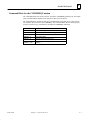
CMM Configuration Modes
The CMM configuration mode selects the communication protocol for each serial port on the
module. There are nine possible configuration modes for the CMM module:
2–10
D
CCM ONLY - CCM protocol on both ports
D
CCM/RTU - CCM protocol on port 1, RTU protocol on port 2
D
RTU/CCM - RTU protocol on port 1, CCM protocol on port 2
Series 90 PLC Serial Communications User’s Manual – November 2000
GFK-0582D
CCM Modules
D
RTU ONLY - RTU protocol on both ports
D
SNP ONLY - SNP and SNP-X protocols on both ports
D
SNP/CCM - SNP and SNP-X protocols on port 1, CCM protocol on port 2
D
CCM/SNP - CCM protocol on port 1, SNP and SNP-X protocols on port 2
D
SNP/RTU - SNP and SNP-X protocols on port 1, RTU protocol on port 2
D
RTU/SNP - RTU protocol on port 1, SNP and SNP-X protocols on port 2
2
A different Soft Switch Data Screen is displayed for each configuration mode.
The factory default is CCM protocol on both ports. Make sure that the proper protocol is selected. If you are using SNP multidrop, make sure that the proper SNP ID has been stored to
the PLC CPU. Note: If you change the CMM’s SNP ID via the programming software, it is
necessary to reset the CMM in order for the new SNP ID to take effect. Resetting the CMM
can be done by either pressing the CMM’s “Restart” pushbutton, or by power–cycling the PLC
rack that contains the CMM.
GFK-0582D
Chapter 2 The Communications Coprocessor Modules
2–11
2
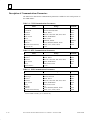
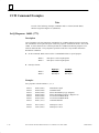
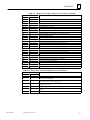
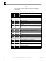
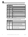
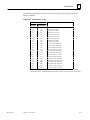
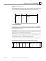
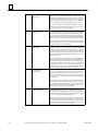
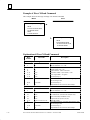
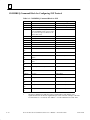
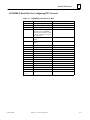
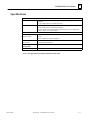
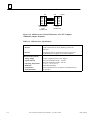
Description of Communications Parameters
The tables below describe the communications parameters available for each serial protocol on
the CMM module:
ÁÁÁÁÁÁÁÁÁÁ
ÁÁÁÁÁÁÁÁÁÁÁÁ
ÁÁÁÁÁ
ÁÁÁÁÁÁÁÁÁÁ
ÁÁÁÁÁÁÁÁÁÁÁÁ
ÁÁÁÁÁ
ÁÁÁÁÁÁÁÁÁÁ
ÁÁÁÁÁÁÁÁÁÁÁÁ
ÁÁÁÁÁ
ÁÁÁÁÁÁÁÁÁÁ
ÁÁÁÁÁÁÁÁÁÁÁÁ
ÁÁÁÁÁ
ÁÁÁÁÁÁÁÁÁÁ
ÁÁÁÁÁÁÁÁÁÁÁÁ
ÁÁÁÁÁ
ÁÁÁÁÁÁÁÁÁÁ
ÁÁÁÁÁÁÁÁÁÁÁÁ
ÁÁÁÁÁ
ÁÁÁÁÁÁÁÁÁÁ
ÁÁÁÁÁÁÁÁÁÁÁÁ
ÁÁÁÁÁ
ÁÁÁÁÁÁÁÁÁÁ
ÁÁÁÁÁÁÁÁÁÁÁÁ
ÁÁÁÁÁ
ÁÁÁÁÁÁÁÁÁÁ
ÁÁÁÁÁÁÁÁÁÁÁÁ
ÁÁÁÁÁ
ÁÁÁÁÁÁÁÁÁÁ
ÁÁÁÁÁÁÁÁÁÁÁÁ
ÁÁÁÁÁ
ÁÁÁÁÁÁÁÁÁÁ
ÁÁÁÁÁÁÁÁÁÁÁÁ
ÁÁÁÁÁ
ÁÁÁÁÁÁÁÁÁÁ
ÁÁÁÁÁÁÁÁÁÁÁÁ
ÁÁÁÁÁ
ÁÁÁÁÁÁÁÁÁÁ
ÁÁÁÁÁÁÁÁÁÁÁÁ
ÁÁÁÁÁ
ÁÁÁÁÁÁÁÁÁÁ
ÁÁÁÁÁÁÁÁÁÁÁÁ
ÁÁÁÁÁ
ÁÁÁÁÁÁÁÁÁÁ
ÁÁÁÁÁÁÁÁÁÁÁÁ
ÁÁÁÁÁ
ÁÁÁÁÁÁÁÁÁÁ
ÁÁÁÁÁÁÁÁÁÁÁÁ
ÁÁÁÁÁ
ÁÁÁÁÁÁÁÁÁÁ
ÁÁÁÁÁÁÁÁÁÁÁÁ
ÁÁÁÁÁ
ÁÁÁÁÁÁÁÁÁÁ
ÁÁÁÁÁÁÁÁÁÁÁÁ
ÁÁÁÁÁ
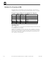
Table 2-1. CCM Communications Parameters
Field
CCM Enable
CCM Mode
Interface1
Data Rate
Flow Control
Parity
Retry Count
Timeout
Modem Turnaround Delay
CCM CPU ID
Range
YES, NO
SLAVE, MASTER, PEER
RS232, RS485
300, 600, 1200, 2400, 4800, 9600, 19200
NONE, HARDWARE
ODD, NONE
NORMAL, SHORT
LONG, MEDIUM, SHORT, NONE
NONE, 10 ms, 100 ms, 500 ms
1-254
Default
YES
SLAVE
RS232
19200
NONE
ODD
NORMAL
LONG
NONE
1
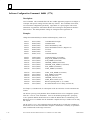
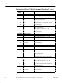
Table 2-2. RTU Communications Parameters
Field
RTU Enable
Interface1
Data Rate
Flow Control
Parity
Station Address
Range
YES, NO
RS232, RS485
300, 600, 1200, 2400, 4800, 9600, 19200
NONE, HARDWARE
ODD, EVEN, NONE
1 - 247
Default
YES
RS232
19200
NONE
ODD
1
ÁÁÁÁÁÁÁÁÁÁ
ÁÁÁÁÁÁÁÁÁÁÁÁ
ÁÁÁÁÁ
ÁÁÁÁÁÁÁÁÁÁ
ÁÁÁÁÁÁÁÁÁÁÁÁ
ÁÁÁÁÁ
ÁÁÁÁÁÁÁÁÁÁ
ÁÁÁÁÁÁÁÁÁÁÁÁ
ÁÁÁÁÁ
ÁÁÁÁÁÁÁÁÁÁ
ÁÁÁÁÁÁÁÁÁÁÁÁ
ÁÁÁÁÁ
ÁÁÁÁÁÁÁÁÁÁ
ÁÁÁÁÁÁÁÁÁÁÁÁ
ÁÁÁÁÁ
ÁÁÁÁÁÁÁÁÁÁ
ÁÁÁÁÁÁÁÁÁÁÁÁ
ÁÁÁÁÁ
ÁÁÁÁÁÁÁÁÁÁ
ÁÁÁÁÁÁÁÁÁÁÁÁ
ÁÁÁÁÁ
ÁÁÁÁÁÁÁÁÁÁ
ÁÁÁÁÁÁÁÁÁÁÁÁ
ÁÁÁÁÁ
ÁÁÁÁÁÁÁÁÁÁ
ÁÁÁÁÁÁÁÁÁÁÁÁ
ÁÁÁÁÁ
ÁÁÁÁÁÁÁÁÁÁ
ÁÁÁÁÁÁÁÁÁÁÁÁ
ÁÁÁÁÁ
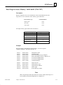
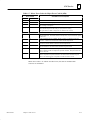
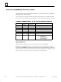
Table 2-3. SNP Communications Parameters
Field
SNP Enable
SNP Mode
Interface1
Data Rate
Flow Control
Parity
Stop Bits
Timeout
Modem Turnaround Delay
Range
YES, NO
SLAVE, MASTER
RS485, RS232
300, 600, 1200, 2400, 4800, 9600, 19200
NONE, HARDWARE
ODD, EVEN, NONE
1, 2
LONG, MEDIUM, SHORT, NONE
NONE, 10 ms, 100 ms, 500 ms
Default
YES
SLAVE
RS485
19200
NONE
ODD
1
LONG
NONE
1 For the CMM311 module, port 1 is RS-232 only.
2–12
Series 90 PLC Serial Communications User’s Manual – November 2000
GFK-0582D
CCM Modules
2
Notes on Communication Parameters
Interface. (CCM, RTU, and SNP) The Interface field specifies the type of electrical interface
used at this serial port. Valid selections are RS-485 or RS-232. Note that for the CMM311
module, port 1 operates as RS-232 only.
Flow Control. (CCM, RTU, and SNP) The Flow Control field specifies the method of flow
control to use at this serial port. Valid selections are NONE or HARDWARE. The timing diagrams below illustrate the state of the flow control lines for flow control = NONE and HARDWARE. Note: The CMM modules do not support harware flow control when used with an
RS–485 interface.
The NONE selection makes use of the signals Transmit Data (TD) and Receive Data (RD) only.
The signal Request to Send (RTS), however, is used as a modem keying signal. The RTS signal
is energized for the Modem Turnaround Delay interval and during the character transmission;
the RTS signal is then immediately de-energized.
RTS
(from CMM)
TD
(from CMM)
Figure 2-7. Flow Control = NONE, MODEM TURNAROUND DELAY=0
RTS
(from CMM)
100 ms
TD
(from CMM)
Figure 2-8. Flow Control = NONE, MODEM TURNAROUND DELAY=100 ms
The HARDWARE selection makes use of the Transmit Data (TD), Receive Data (RD), Request
to Send (RTS, Clear to Send (CTS), Data Carrier Detect (DCD), and Data Terminal Ready
(DTR). The signals are used in the manner specified by the RS-232 and RS-422/RS-485 electrical standards; these signals are described below:
GFK-0582D
Chapter 2 The Communications Coprocessor Modules
2–13
2
RTS
(from CMM)
Max. of
2 sec.
CTS
(to CMM)
TD
(from CMM)
Figure 2-9. Flow Control = HARDWARE
Request to Send (RTS) and Clear to Send (CTS). These signals are used to control the transmission of data to the remote device. The RTS signal is asserted at the beginning of each transmission by the CMM. The actual characters are not transmitted, however, until the CTS signal
is returned. Once the characters are transmitted, the RTS signal is immediately removed. As in
the case of NONE flow control, a nonzero Modem Turnaround Delay is NOT used to control
the operation of the RTS signal. It is simply used to adjust the appropriate protocol timers for
any delay in receiving the CTS signal once the RTS signal is asserted.
Data Carrier Detect (DCD) and Data Terminal Ready (DTR). These signals are used to control the reception of data from the remote device. The DCD signal, when received from the
remote device, essentially forms a request to the CMM to prepare for reception of data. The
CMM, in turn, asserts the DTR signal when it is prepared to receive the data. In the CMM,
DTR is always asserted; it is never turned off.
Timeout. (CCM) The Timeout field displays the length of timeouts used for CCM on the target port. Valid selections are LONG, MEDIUM, SHORT, or NONE.
Timeout. (SNP) The Timeout field specifies a set of values for each of the SNP timers. Valid
selections include LONG, MEDIUM, SHORT, or NONE. The SNP Timeout selections and the
related timer values are specified in the following table. The timers in the second half of the
table are derived from earlier timer values via the specified equation.
Modem Turnaround Delay. (CCM and SNP Only) The Modem Turnaround Delay field
specifies the length of time required by the intervening modems to turn the link around. In the
case that NONE flow control is selected, the Modem Turnaround Delay also specifies the
length of time that the Request to Send (RTS) signal is asserted before any characters are transmitted. Valid selections are NONE, 10 ms, 100 ms, or 500 ms.
Note
Timeout values used by Logicmaster 90 software and the Series 90-70 and 90-30
CPUs are also listed for comparison.
2–14
Series 90 PLC Serial Communications User’s Manual – November 2000
GFK-0582D
CCM Modules
2
ÁÁÁÁÁÁÁÁ
ÁÁÁÁ
ÁÁÁÁ
ÁÁÁÁ
ÁÁÁÁ
ÁÁÁÁ
ÁÁÁÁ
ÁÁÁÁ
ÁÁÁÁÁÁÁÁ
ÁÁÁÁ
ÁÁÁÁÁÁÁÁ
ÁÁÁÁÁÁÁÁ
ÁÁÁÁ
ÁÁÁÁ
ÁÁÁÁÁÁÁÁ
ÁÁÁÁ
ÁÁÁÁÁÁÁÁ
ÁÁÁÁÁÁÁÁ
ÁÁÁÁ
ÁÁÁÁ
ÁÁÁÁÁÁÁÁ
ÁÁÁÁ
ÁÁÁÁ
ÁÁÁÁ
ÁÁÁÁ
ÁÁÁÁ
ÁÁÁÁ
ÁÁÁÁ
ÁÁÁÁÁÁÁÁ
ÁÁÁÁ
ÁÁÁÁ
ÁÁÁÁ
ÁÁÁÁ
ÁÁÁÁ
ÁÁÁÁ
ÁÁÁÁ
ÁÁÁÁÁÁÁÁ
ÁÁÁÁ
ÁÁÁÁ
ÁÁÁÁ
ÁÁÁÁ
ÁÁÁÁ
ÁÁÁÁ
ÁÁÁÁ
ÁÁÁÁÁÁÁÁ
ÁÁÁÁ
ÁÁÁÁ
ÁÁÁÁ
ÁÁÁÁ
ÁÁÁÁ
ÁÁÁÁ
ÁÁÁÁ
ÁÁÁÁÁÁÁÁ
ÁÁÁÁÁÁÁÁÁÁÁÁÁÁÁÁÁÁÁÁÁÁ
ÁÁÁÁ
ÁÁÁÁ
ÁÁÁÁ
ÁÁÁÁ
ÁÁÁÁ
ÁÁÁÁ
ÁÁÁÁ
ÁÁÁÁÁÁÁÁ
ÁÁÁÁÁÁÁÁÁÁÁÁÁÁÁÁÁÁÁÁÁÁ
ÁÁÁÁÁÁÁÁ
ÁÁÁÁÁÁÁÁÁÁÁÁÁÁÁÁÁÁÁÁÁÁ
ÁÁÁÁÁÁÁÁ
ÁÁÁÁÁÁÁÁÁÁÁÁÁÁÁÁÁÁÁÁÁÁ
ÁÁÁÁÁÁÁÁ
ÁÁÁÁÁÁÁÁÁÁÁÁÁÁÁÁÁÁÁÁÁÁ
Table 2-4. SNP Timer Values for Timeout Selections
SNP Timer
T1
T2
T3’
T4
T5
Transmission Delay1
COMMREQ timeout2
T3
T3’’
T5’
T5’’
None
Short
Medium
Long
LM90
90-30
5 ms
5 ms
5 ms
5 ms
10 ms
5 ms
2 sec
500 ms
1 sec
2 sec
3 sec
1 sec
Disabled
5 sec
10 sec
10 sec
10 sec
10 sec
50 ms
50 ms
50 ms
50 ms
100 ms
N/A
Disabled
2 sec
5 sec
Disabled
10 sec
10 sec
0 sec
0 sec
0 sec
0 sec
0 sec
0 sec
30 sec
30 sec
30 sec
30 sec
N/A
N/A
T3’ - 80 character times
T3 + 65 seconds
T5 + 80 character times
T5 + Transmission Delay + twice next message transmission time.
90-70
5 ms
500 ms
10 sec
N/A
10 sec
0 sec
N/A
1 The Transmission Delay specifies the length of time required for the data to transfer from the initiating
device to the responding device. This duration is also referred to as the wire time. Examples where this
value may be changed to a non-zero value include instances where satellite links are used to transfer data.
2 The COMMREQ Timeout specifies the maximum length of time that a COMMREQ can remain in process.
If the COMMREQ command cannot be completed before this time interval, the COMMREQ processing is
terminated, and an error code is returned in the COMMREQ Status Word indicating that a COMMREQ
timeout has occurred.
See the “SNP Timers” section of Chapter 7, Protocol Definition, for a complete description of the
SNP timers.
GFK-0582D
Chapter 2 The Communications Coprocessor Modules
2–15
Chapter
3 Series 90 CPU Serial Ports
3
section level 1 1
figure bi level 1
table_big level 1
Overview
This chapter describes the serial communications ports on the Series 90–30 and Series 90–70
CPU models. This chapter is divided into the following main topics:
GFK-0582D
H
Series 90–30 CPU Serial Ports
H
Series 90–70 Serial Ports
H
General Series 90 CPU Serial Communication Information
H
Configuring Serial Ports 1 and 2 with a COMMREQ
3–1
3
Series 90–30 CPU Serial Ports
H
All Series 90–30 CPUs have a built–in serial port that is accessed through a connector on
the PLC power supply.
H
CPUs 351, 352, and 363 each have two additional serial ports that are accessed by connectors on their faceplates. See Figure 2–1 below.
Serial Communications Features of CPUs 351, 352, and 363
This manual only discusses the serial communications features of these CPUs. A detailed description of their other hardware features can be found in the “CPUs” chapter of the Series
90-30 Programmable Controller Installation and Hardware Manual, GFK-0356P ( or later versions).
These three CPUs (IC693CPU351/352/363) have three serial ports. The standard SNP port is
accessed through the power supply connector. Ports 1 and 2 are accessed by connectors on the
front of the module (shown in the figure below). For many applications, each port serves as an
independent window into the PLC for communicating with other devices, such as industrial
computers, pagers, and operator interface terminals.
These serial ports are configurable using GE Fanuc’s Logicmaster, Control, or VersaPro PLC
software. Ports 1 and 2 can also be configured using a Communications Request (COMMREQ) Instruction in a ladder logic program.
P2
CPU 351
PS
PORT
P1
SNP
P1
CPU 363
P2
ON
OFF
ON/RUN
PIN 1
OFF/
STOP
PORT 1
RS-232
PORT 1
RS-232
PIN 1
PORT 2
RS-485
PIN 1
PORT 2
RS-485
FRAME
CPU363
Shield Ground
Connector
CPU351/352
Figure 3-1. CPU Features (CPUs 351 and 352 look identical except for labeling)
3–2
Series 90 PLC Serial Communications User’s Manual – November 2000
GFK-0582D
CPU Serial Ports
3
Serial Ports Details
These ports can be used for serial interfaces to Operator Interface terminals (OIs), Human to
Machine Interface terminals (HMIs), pagers, programmers, modems, and other serial communications devices. Also, CPU352 and CPU363 support the Serial I/O Read function that enables them to read input from devices such as bar code readers. This function is not supported
on the CPU351.
H
Port 1, the top port on these CPUs, is a non–isolated RS-232 compatible port. Port 1 is
accessed through a 6-pin RJ-11 connector on the front of the module. This connector has
female contacts and is similar to modular jacks commonly used for telephones and modems. GE Fanuc’s serial cable, part number IC693CBL316, is a convenient way to connect
to this port. Chapter 8 of this manual contains a data sheet on this cable.
H
Port 2, the bottom port, is an isolated, RS-485 compatible port. It is accessed through a
female, 15-pin, D–shell connector on the front of the module.
H
Standard SNP Port, accessed through the female, 15-pin, D–shell connector on the PLC
power supply, is a non–isolated RS–485 compatible port.
LED Indicators
The CPUs 351, 352, and 363 have three LED indicators which enable you to determine the status
of the serial port activity on the CPU 351/352 without having a terminal connected.
H
The SNP or PS LED (top LED) is ON when data is being transferred through the Standard
SNP serial port, whose connector (RS–422/485) is located on the PLC power supply.
H
The P1 LED (middle LED), will be ON when data is being transferred through Port 1, the
RS-232 port.
H
The P2 LED (bottom LED), will be ON when data is being transferred through Port 2, the
RS-422/485 port.
Serial Communications Features and Protocol Support
Serial Ports 1 and 2 on CPUs 351, 352, and 363 and the standard SNP serial port (accessed
through connector on PLC power supply) have different features and are discussed separately.
Ports 1 and 2 are accessed by connectors on the front of the CPU. Port 3 is accessed through a
connector on the PLC power supply. Features available on Ports 1 and 2 were added over a
period of time in various firmware releases. Firmware releases pertaining to communications
features are documented in the following tables. A complete firmware release history is available on the technical support section of the GE Fanuc web site:
http://www.gefanuc.com/support/PLC .
GFK-0582D
Chapter 3 – Series 90 CPU Serial Ports
3–3
3
Table 3-1. Features of CPU351 Serial Ports 1 and 2
Feature
Firmware Release
6.52
Firmware Release
8.00
Firmware Release
9.00
Firmware Release
10.00
SNP Master/Slave
Yes*
Yes
Yes
Not Available**
SNP–X Master/
Slave
Yes*
Yes
Yes
Not Available**
RTU Slave
No
Yes*
Yes
Not Available**
Break–Free SNP
No
No
Yes*
Not Available**
Serial I/O Write
No
Yes*
Yes*
Not Available**
Serial I/O Read
No
No
No
Not Available**
* Indicates CPU firmware release in which the feature was first available. When CPU351 was initially
released, it was equipped with firmware release 6.00.
** The latest firmware available for CPU351 is release 9.11. It is not planned to upgrade the CPU351
beyond that release.
Table 3-2. Features of CPU352 Serial Ports 1 and 2
Feature
Firmware Release
7.00
Firmware Release
8.00
Firmware Release
9.00
Firmware Release
10.00
SNP Master/Slave
Yes*
Yes
Yes
Yes
SNP–X Master/
Slave
Yes*
Yes
Yes
Yes
RTU Slave
No
Yes*
Yes
Yes
Break–Free SNP
No
No
Yes*
Yes
Serial I/O Write
No
Yes*
Yes
Yes
Serial I/O Read
No
No
No
Yes*
* Indicates CPU firmware release in which the feature was first available. When CPU352 was initially released, it was equipped with firmware release 7.00.
Table 3-3. Feaures of CPU363 Serial Ports 1 and 2
Feature
Firmware Release 9.00**
Firmware Release 10.00
SNP Master/Slave
Yes
Yes
SNP–X Master/Slave
Yes
Yes
RTU Slave
Yes
Yes
Break–Free SNP
Yes*
Yes
Serial I/O Write
Yes
Yes
Serial I/O Read
No
Yes*
* Indicates CPU firmware release in which the feature was first available.
** When CPU363 was initially released, it was equipped with firmware release 9.00.
3–4
Series 90 PLC Serial Communications User’s Manual – November 2000
GFK-0582D
CPU Serial Ports
3
Standard SNP Port (Accessed Through Power Supply Connector)
All Series 90–30 CPUs have a standard SNP serial port that is accessed through a connector on
the PLC power supply. This serial port only supports the SNP Slave and SNP–X Slave
protocols. Break–Free SNP became the default protocol on this port, starting with firmware
release 8.20 for CPUs 311 – 341 and 9.00 for CPUs 350 – 364. For CPUs equipped with
firmware earlier than those two releases, the default protocol is standard (Break–Enabled) SNP.
Break–Free SNP protocol is discussed in a later section of this chapter.
The most common use for this port is communicating with a personal computer running the
PLC programming software; however, it is capable of other uses, such as communicating with
an operator interface device. In either case, the personal computer or operator interface device
would act as the master and the PLC as the slave because this port only supports the slave
versions of the SNP and SNP–X protocols.
GFK-0582D
Chapter 3 – Series 90 CPU Serial Ports
3–5
3
Series 90–70 CPU Serial Ports
H
All Series 90–70 CPUs have at least one built–in serial port, the standard SNP port. It is
called Serial Port 3 on CPUs that have three serial ports.
H
CPUs CPX772, CPX782, CPX928, and CPX935 each have two additional serial ports,
Ports 1 and 2, that were first activated in firmware release 7.80. CPUs CGR772 and
CGR775 each have two additional serial ports, Ports 1 and 2, that were first activated in
firmware release 7.85. The following figure shows the location of these ports.
a45734A
LED P1
LED P2
Î
ÎÎ
Î
ÎÎ
ÎÎ
Î
ÎÎ
ÎÎ
Î
ÎÎÎÎ
Î
ÎÎÎ
ÎÎ
Î
ÎÎ
Î
ÎÎ
ÎÎ
Î
ÎÎ
ÎÎÎ
Î
ÎÎ
ÎÎ
Î
ÎÎ
ÎÎ
Î
ÎÎ
Î
Î
ÎÎ
ÎÎ
ÎÎÎ
Î
ÎÎ
Î
ÎÎÎ
Î
ÎÎ
Î
Î
ÎÎ
Î
ÎÎ
Î
ÎÎ
Î
ÎÎ
Î
ÎÎ
Î
ÎÎ
Î
ÎÎ
Î
ÎÎ
Î
ÎÎ
Î
ÎÎ
Î
ÎÎ
Î
ÎÎ
Î
ÎÎ
Î
ÎÎ
Î
ÎÎ
Î
Î
ÎÎ
Î
Î Î
ÎÎ
CPX 935
TOP
OFF
LED P3
B
A
T
T
E
R
Y
PIN 1
SERIAL PORT 1
SERIAL PORT 2
PIN 1
ON
REMOTE PROGRAMMER
MEMORY PROTECT
KEY POSITION
FRONT
OK
P1
RUN
P2
EN
P3
MEM PROTECT
ON = OK, ENABLED,
PROTECTED
RUN WITH
OUTPUTS
ENABLED
RUN WITH
OUTPUTS
DISABLED
STOP
BATTERY
CONNECTORS
INSTALL NEW
BATTERY BEFORE
UNPLUGGING OLD
BATTERY. USE
IC697ACC701
MODULE FUNCTION
96 MHz 32 BIT CENTRAL
PROCESSING UNIT
SERIAL PORT 1
RS-232
SERIAL PORT 2
RS-485
COMPATIBLE
FACTORY TEST
SERIAL PORT 3
PIN 1
SERIAL PORT 3
RS-485
COMPATIBLE
USE THIS MODULE
IN SLOT 1 ONLY
MODULE
IC697CPX935
LABEL
44A726758–154R01
Figure 3-2. Example of a Series 90–70 CPU with Three Serial Ports
3–6
Series 90 PLC Serial Communications User’s Manual – November 2000
GFK-0582D
3
CPU Serial Ports
Series 90–70 CPU Serial Ports Details
H
Port 1, the top port on these CPUs, is RS-232 compatible. It has a 6-pin, female RJ-11
connector. This connector looks similar to the smaller modular jacks commonly used for
telephones and modems. GE Fanuc’s serial cable, part number IC693CBL316, is a
convenient way to connect to this port. Chapter 8 of this manual contains a data sheet for
cable IC693CBL316.
H
Port 2, the middle port, is RS-485 compatible, and is isolated through an optocoupler. It is
has a 15-pin, female D–shell connector.
H
Port 3 (Standard SNP Port), the bottom port, is also RS–485 compatible, but is not isolated. It has a 15–pin, female D–shell connector.
Series 90–70 CPU LED Indicators
These CPUs have three serial port LED indicators, labeled P1, P2, and P3, which enable you to
determine the status of serial port activity on the CPUs without having a terminal connected. For
location of these LEDs, please see the previous figure.
H
The P1 LED (top LED) is ON when data is being transferred through Port 1.
H
The P2 LED (middle LED) is ON when data is being transferred through Port 2.
H
The P2 LED (bottom LED), is ON when data is being transferred through Port 3.
Features Supported on Series 90–70 CPU Serial Ports
Table 3-4. Serial Port Features for CPX CPUs
Serial Port Features Supported on CPUs CPX772, CPX782, CPX928, and CPX935
Feature
Ports 1 and 2
Port 3
Yes, starting with Firmware Release 7.80
Yes
No
No
Yes, starting with Firmware Release 8.00
No
SNP–X protocol (slave or master)
No
No
RTU protocol
No
No
CCM protocol
No
No
Serial I/O
No
No
Program Load/Store
Yes, starting with Firmware Release 8.00
Yes
Datagrams
Yes, starting with Firmware Release 8.00
Yes
MSG Mode for C programmer
“printf” support
No
Yes
C–Debugger support
No
Yes
RS–232
Port 1 only
No
RS–422/485
Port 2 only
Yes
Yes
No
Port 2 only
No
SNP (slave) protocol
SNP (master) protocol
Break–Free SNP protocol
Configurable with COMMREQ
Electrical Isolation
GFK-0582D
Chapter 3 – Series 90 CPU Serial Ports
3–7
3
Table 3-5. Serial Port Features for CGR CPUs
Serial Port Features Supported on CPUs CGR772 and CGR935
Feature
Ports 1 and 2
Port 3
Yes, starting with Firmware Release 7.85
Yes
SNP (master) protocol
No
No
Break–Free SNP protocol
No
No
SNP–X protocol (slave or master)
No
No
RTU protocol
No
No
CCM protocol
No
No
Serial I/O
No
No
Program Load/Store
No
Yes
Datagrams
No
Yes
MSG Mode for C programmer
“printf” support
No
Yes
C–Debugger support
No
Yes
RS–232
Port 1 only
No
RS–422/485
Port 2 only
Yes
Yes
No
Port 2 only
No
SNP (slave) protocol
Configurable with COMMREQ
Electrical Isolation
3–8
Series 90 PLC Serial Communications User’s Manual – November 2000
GFK-0582D
CPU Serial Ports
3
General Series 90 CPU Serial Communication Information
Pin Assignments for CPU Serial Ports 1 and 2
The pin assignments in the next two tables only apply to the following CPUs:
H
Series 90–30: CPU351, CPU352, and CPU363
H
Series 90–70: CPX772, CPX782, CPX928, CPX935, CGR772, and CGR935
Table 3-6. Port 1 (Non–Isolated) RS–232 Signals
Pin
Number
1*
2
3
4
5
6
Signal
Name
CTS
TXD
0V
0V
RXD
RTS
Description
Clear To Send
Transmit Data
Signal Ground
Signal Ground
Receive Data
Request to Send
* See the previous figures for location of pin 1.
Table 3-7. Port 2 (Isolated) RS-485 Signals
Pin
Number
1*
2
3
4
5
6
7
8
9
10
11
12
13
14
15
Signal
Name
Shield
NC
NC
NC
+5VDC
RTS(A)
SG
CTS(B‘)
RT
RD(A‘)
RD(B‘)
SD(A)
SD(B)
RTS(B’)
CTS(A’)
Description
Cable Shield
No Connection
No Connection
No Connection
Logic Power **
Differential Request to Send
Signal Ground
Differential Clear To Send
Resistor Termination
Differential Receive Data
Differential Receive Data
Differential Send Data
Differential Send Data
Differential Request To Send
Differential Clear To Send
* See the previous figures for location of pin 1.
** Note that Pin 5 provides Isolated +5 VDC power
(100 mA maximum) for powering external options.
GFK-0582D
Chapter 3 – Series 90 CPU Serial Ports
3–9
3
Series 90 PLC Standard, (Non–Isolated) SNP Serial Port
The standard Series 90 PLC serial port has a 15–pin D–type female connector and is
RS-422/485 compatible. An RS-232 to RS-422 converter is required to interface to systems
that provide RS-232 compatible interfaces. It is found an all Series 90 PLCs:
H Series 90-70 PLC – Found on all Series 90–70 CPUs. This is the only port on most CPUs.
On CPUs with three ports, this port is called Serial Port 3.
H
Series 90-30 PLC – Found on all Series 90–30 CPUs. Accessed through connector on PLC
power supply on all CPUs (see next figure).
a43832
Pin 1
ÎÎÎÎÎ
ÎÎÎÎÎ
RS-485
COMPATIBLE
SERIAL PORT
Figure 3-3. Series 90–30 CPU Serial Port Connector on Power Supply
H
This serial port is RS-485 compatible, and uses the GE Fanuc SNP (Series Ninety Protocol)
protocol (slave only). The IC690ACC901 Miniconverter is usually used to connect this
port to a personal computer’s RS–232 serial port. Break-Free SNP became the default
protocol on all serial ports on the Series 90-30 CPUs, starting with Firmware Release 9.00
for CPUs 350 - 364, and Firmware Release 8.20 for CPUs 311 - 341. BreakFree SNP is
discussed in a later section of this chapter.
H
The serial port connector is only functional in a power supply that is installed in a baseplate
that also contains the CPU. It is not functional on a power supply that is installed in an
expansion or remote baseplate.
H
Any device connected to the serial port that uses +5 VDC power from the Series 90-30
power supply must be included in the calculation for maximum power consumption (see
the heading “Power Supply Loading Calculations” in Chapter 12 of GFK–0356 for details).
Caution
Care must be taken that common mode voltage specifications are met for
connections to this non–isolated serial port. Common mode conditions that
exceed those specified will result in errors in transmission and/or damage to
Series 90 PLC components. Common mode specifications are discussed in
Appendix C. When the common mode voltage specification is exceeded, a
port isolator such as the GE Fanuc IC690ACC903 must be used. See Appendix G for details on this port isolator.
3–10
Series 90 PLC Serial Communications User’s Manual – November 2000
GFK-0582D
CPU Serial Ports
3
Series 90 PLC Standard SNP Serial Port Connector Pin–Out
The figure below shows the serial port orientation and connector layout for the Series 90 CPUs,
and the following table shows the pin numbering and signal assignment for these connectors.
SERIES 90–70 PLC
8
15
PIN
1
9
SERIES 90–30 PLC
PIN
1
a44521
9
15
8
NOTE
SERIES 90 PLC CONNECTORS
USE METRIC HARDWARE.
Figure 3-4. Series 90 PLC, RS-422 Serial Port Connector Configuration
Table 3-8. Pin–out for Standard SNP Serial Port Connectors
Pin Number
Signal Name
1
2
3
4
Shield
5
6
7
8
9
10
11
12
13
14
15
+5V *
RTS (A)
Signal Ground
CTS (B’)
RT *
RD (A’)
RD (B’)
SD (A)
SD (B)
RTS (B)
CTS (A’)
ATCH *
Description
No Connection
No Connection
Hand-Held Programmer attach signal
+5V Power for: HHP and RS-232/485 Converter
Request To Send
Signal Ground, OV
Clear To Send
Terminating Resistor for RD **
Receive Data
Receive Data
Send Data
Send Data
Request To Send
Clear To Send
* Signals available at the Connector but are not included in the RS-422 specification. SD (Send Data) and RD (Receive Data)
are the same as TXD and RXD (used in the Series Six PLC). (A) and (B) are the same as - and + . A and B denote outputs,
and A’ and B’ denote inputs.
** Termination resistance for the Receive Data (RD) signal needs to be connected only on units at the end of the lines. This
termination is made on the Series 90 PLC products by connecting a jumper between pins 9 and 10 inside the 15-pin D-shell
with the following exception. For Series 90-70 PLCs with Catalog Numbers IC697CPU731J, and IC697CPU771G and
earlier the termination for RD at the PLC is implemented by a jumper between pins 9 and 11.
GFK-0582D
Chapter 3 – Series 90 CPU Serial Ports
3–11
3
Break-Free SNP Protocol
Break-Free SNP has become the default protocol on some of the Series 90 CPUs. The table
below identifies which products support this feature. The purpose of this feature is to improve
serial communications when modems are used. Break–Free SNP simplifies modem
communications with Series 90 PLCs by eliminating the requirement for a serial break at the
start of each SNP and SNP–X session. Consequently, modem pairs that alter the timing or
characteristics of breaks from SNP/SNP–X masters may be used successfully.
Break–Free operation is completely transparent to the user. When normal breaks are received,
SNP/SNP–X communications operate identical to standard SNP communications. When Attach
and X–Attach messages are received, these are also recognized without a preceding break.
Modified breaks (for example, breaks transformed to a single ASCII NUL character, with or
without a framing error) are ignored.
The Break–Free feature requires data rates of 1200 baud and higher. Breaks are required at 300
and 600 baud rates. The PLC’s auto–baud feature also requires breaks. Auto–baud permits
Series 90–30 CPUs with no stored configuration to communicate at either 9600 or 19,200 baud,
odd parity, and one stop bit. Note that auto–baud is incompatible with modem communications
because a stored configuration is required to set the serial port for NO PARITY.
Break–Free SNP is compatible with existing SNP master units such as computers running PLC
programming software, or PCM modules. In a few applications, primarily where a combination
of multi-drop SNP communications and very short PLC sweep times are used, users may desire,
for performance reasons, to disable Break-Free SNP. Break-Free SNP can be disabled and
re-enabled via Communications Request (COMMREQ) instructions 7004 and 7005, which are
detailed in Chapter 6 of this manual.
This feature can be added to older versions of the applicable CPUs through a firmware upgrade
– contact your GE Fanuc distributor for information.
Table 3-9. Series 90 Products Supporting Break–Free SNP Feature
3–12
Product
Break–Free SNP
Series 90–30 CPU350 – 364
Supported on all serial communications ports
starting with firmware release 9.00
Series 90–30 CPU311, 313, 323, 331, 341
Supported starting with firmware release 8.20
Series 90–70 CPX772, 782, 928, 935
Supported only on Ports 1 and 2 starting with
firmware release 8.00
Series 90–30 CPU340
Series 90–70 CPU731 – 927
Series 90–70 CGR772, 935
Not supported
Series 90 PLC Serial Communications User’s Manual – November 2000
GFK-0582D
CPU Serial Ports
3
Serial I/O Protocol
The Serial I/O protocol allows users to write a custom protocol for communicating with various
serial devices such as bar code readers or pagers (not all CPUs support both Serial I/O modes –
see table below). Serial I/O has two modes: Read and Write. Support for Serial I/O is detailed
in the table below. Chapter 9 of this manual explains how to use this protocol. Serial I/O can
be added to older versions of CPU351, 352, and 363 through a firmware upgrade – contact your
GE Fanuc distributor for information.
Table 3-10. Products Supporting the Serial I/O Feature
Product
Serial I/O Write
Serial I/O Read**
CPU351, Ports 1 and 2
Supported starting with firmware release 8.00
Not available*
CPU352, CPU363, Ports 1
and 2
Supported starting with firmware release 8.00
Supported, starting with firmware release 10.00**
CPU351, CPU352, CPU363, Not supported
Standard SNP port (via power
supply connector)
Not supported
Series 90–30 CPUs: 311–341
Series 90–70 CPUs: All
Not supported
Not supported
* Firmware 10.00, required for Serial I/O Read, will not be made available for CPU351.
** The Serial I/O Read feature requires the use of VersaPro 1.1 (or later version) PLC
programming software. It is currently not supported by other programming software.
Serial Communications Problems and Restrictions
Known problems, restrictions, and work–around solutions are documented in the Important
Product Information (IPI) sheet that comes with a new CPU module. The IPI also documents
the latest information on new features and problem corrections that may be too recent to be in
this manual. It also contains information on upgrading older versions of the product. We
recommend you read these IPIs, then retain them as part of your PLC documentation. IPIs can
also be found on the GE Fanuc InfoLink PLC documentation CD and on the GE Fanuc web site
support area (www.gefanuc.com/support/PLC).
Version Support of Product Features
As noted in many of the tables in this chapter, not all versions of a product and not all versions
of the PLC programming software support the various features. If you are using older versions
of the products or software but need or desire to use a later feature not supported, you should
contact your GE Fanuc distributor for information on upgrading to a new version. The
Important Product Information (IPI) sheet that comes with the product usually contains upgrade
information as well (see the previous paragraph). Some firware upgrades may be downloaded
for free from the GE Fanuc web site support area (www.gefanuc.com/support/PLC). Or, an
upgrade kit can be ordered for a nominal cost.
Where to Find Additional Information
The GE Fanuc web site support area (www.gefanuc.com/support/PLC) has additional information on many PLC subjects including serial communications. This site offers such thing as anGFK-0582D
Chapter 3 – Series 90 CPU Serial Ports
3–13
3
swers to Frequently Asked Questions (FAQs), product revision histories, online versions of recently revised publications, an online version of InfoLink, and downloadable files and
upgrades.
CPU Diagnostic Error Codes
If any power–up diagnostic tests fail, one or more diagnostic error codes will be generated. On
both the Series 90–30 and Series 90–70 CPUs, error codes will be displayed on serial port LEDs
P1 and P2. P1 will repeatedly flash the number of times that corresponds to the most significant digit of the error code, and P2 will repeatedly flash the number of times that corresponds to
the least significant digit of the error code. For example, if P1 flashes two times, then pauses,
then flashes two times, etc., it indicates that the most significant digit of the error code is two.
If P2 flashes three times, then pauses, then flashes three times, etc., it indicates the least significant digit of the error code is three. Therefore, the error code 23 would be indicated.
Table 3-11. Error Code Table
Error Code
Error Description
11
Bad Processor Flags
12
Bad Processor Register
13 or 14
3–14
Bad Stack Area
15
DMA Channel 0 not working
16
DMA Channel 1 not working
17
DMA Channel 2 not working
18
DMA Channel 3 not working
19
Address Lines not working
21
H8 Timers not working
22
Bad Interrupt Vector Table
23
Bad Diagnostic RAM Area
24
Bad H8 Cache RAM
25
Unexpected Interrupt
26
Bad System RAM
27
Bad CRC Checksum
28
Bad Dualport RAM
29
Serial Port 1 Loopback failed
31
Watchdog Timer Expired
99
Unspecified Diagnostic Error
Series 90 PLC Serial Communications User’s Manual – November 2000
GFK-0582D
CPU Serial Ports
3
Configuring Serial Ports 1 and 2 with a COMMREQ
Only Ports 1 and 2 on the CPU351, CPU352, CPU363, CPX772, CPX782, CPX928, CPX935,
CGR772, and CGR935 CPUs may be configured with a COMMREQ. When these CPUs are
powered-up, their serial ports are given a default configuration. These default settings remain
in effect unless you change them using your programming software configurator function. You
can also temporarily change the active settings on one of these ports by initiating a Serial Port
Setup COMMREQ, although this will not permanently change the configuration values set by
default or set with configuration software.
Caution
Both serial ports will be returned to their configuration values (set by default or with
configuration software) when power is cycled to the PLC. If power is cycled and
you have previously initiated a COMMREQ to change any serial port settings, you
will need to again initiate the COMMREQ upon power–up if you wish to reinstate
the settings commanded by the COMMREQ.
Using the Serial Port Setup COMMREQ
The PLC COMMREQ ladder instruction is a general purpose instruction used for many different
communication functions and with a wide variety of devices. (General information on this instruction is found in GFK–0467, the Series 90–30/20/Micro PLC CPU Instruction Set Reference Manual,
and GFK–0265, the Series 90–70 PLC Reference Manual.) In order to specify what function the
instruction will be performing and with what device, applicable codes 1are specified for the
COMMREQ’s SYSID and TASK ID inputs. For configuring CPU serial ports, the SYSID must be
0001 (which represents the CPU location: Rack 00, Slot 01) and the TASK ID either 19 decimal
(Port 1) or 20 decimal (Port 2). Length of the data block is 12 words (24 bytes). The format for
the data block of the Serial Port Setup COMMREQ is shown in the next table.
Enable
IN: Address of Data Block First Word
COMM
OK
REQ
SYSID: Rack and Slot Number of CPU
(Always 0001 hex)
IN
FT
SYSID
TASK
TASK: 19 (13hex) = Serial Port 1
20 (14hex) = Serial Port 2
FT: Fault output. Goes High for
COMMREQ Fault.
OK: (Only available on the Series
90–70.) Goes high if the
COMMREQ passes power flow.
Figure 3-5. The COMMREQ Ladder Instruction
GFK-0582D
Chapter 3 – Series 90 CPU Serial Ports
3–15
3
COMMREQ Data Block
Table 3-12. Serial Port Setup COMMREQ Data Block
Word
Parameter*
Word
Parameter*
Start address +0
Command = FFF0 (hex)
Start address +8
Bits per Character
Start Address +1
Protocol
Start Address +9
Stop Bits
Start Address +2
Port Mode
Start Address +10
Interface
Start Address +3
Data Rate
Start Address +11
Duplex Mode
Start Address +4
Parity
Start Address +12
Device Identifier bytes 1 and 2
Start Address +5
Flow Control
Start Address +13
Device Identifier bytes 3 and 4
Start Address +6
Turnaround Delay
Start Address +14
Device Identifier bytes 5 and 6
Start Address +7
Timeout
Start Address +15
Device Identifier bytes 7 and 8
*The values for these parameters can be selected from the choices in the following table.
Note: The SNP ID can also be changed by sending an SNP COMMREQ with the Change SNP ID command (7002).
COMMREQ Timing Consideration
The Serial Port Setup COMMREQ can be sent any time that the system is running, thereby allowing you to configure a single port without interrupting the other port’s current activity. After sending a valid Serial Port Setup COMMREQ, you should wait a minimum of two seconds
before issuing another COMMREQ to the port that has just been configured.
3–16
Series 90 PLC Serial Communications User’s Manual – November 2000
GFK-0582D
CPU Serial Ports
3
COMMREQ Parameter Description
Note
The validity of values for various parameters in the table below depends on
the type of protocol configured and the availability of options supported by
the firmware version of the CPU.
For example, the Series 90–70 CPUs do not support SNP Master, so the
combination of Protocol parameter = 1 (SNP) and Port Mode = 1 (Master)
is not a valid choice.
The user should consult the tables earlier in this chapter to determine the
features supported by the CPU to be targeted by the COMMREQ.
Table 3-13. Description of COMMREQ Parameters
Parameter
Values
Default
Protocol
0 = DISABLED
3 = RTU
1 = SNP
4 = Reserved
2 = Reserved
5 = Serial I/O
SNP
Port Mode
0 = SLAVE
1 = MASTER
2 = PEER
SLAVE
Data Rate
0 = 300
3 = 2400
6 = 19200
1 = 600
4 = 4800
2 = 1200
5 = 9600
19200
Parity
0 = NONE
1 = ODD
2 = EVEN
ODD
Flow Control
0 = HARDWARE
1 = NONE
2 = SOFTWARE
Turnaround Delay
0 = NONE
3 = 500ms
1 = 10 ms
2 = 100ms
NONE
Timeout
0 = LONG
3 = NONE
1 = MEDIUM
2 = SHORT
LONG
Bits per Character
0 = 7 bits 1 = 8 bits
Stop Bits
0 = 1 stop bit
Interface
0 = RS232 (default for Port 1)
1 = RS485 (default for Port 2)
Duplex Mode
0 = 2-wire
Device Identifier
(8 bytes in length)
This is an identifier that distinguishes this device from
others on the same network (for example: SNP ID,
STA ADDR).
NONE
8 bits
1 = 2 stop bits
1 = 4-wire
1 stop bit
RS232 (P1)
RS485 (P2)
2 = point-to-point
4-wire
NULL
Note that for devices that use an SNP ID of 1,
enter 49 decimal (31 hexadecimal).
GFK-0582D
Chapter 3 – Series 90 CPU Serial Ports
3–17
Chapter
4 Initiating Communications - The COMMREQ
4
section level 1 1
figure bi level 1
table_big level 1
This chapter describes how to initiate communications in ladder programs created with Logicmaster software. The chapter is divided into 3 sections:
D
Section 1: The Communications Request
D
Section 2: The COMMREQ Ladder Instruction
D
Section 3: The COMMREQ Command Block
Section 1 describes the structure and operation of the Communications Request. Section 2 describes the format and content of the COMMREQ Ladder Instruction. Section 3 describes the
format and content of the COMMREQ Command Block.
Note
This chapter pertains only to the CCM, SNP, and SNP-X Protocols, which protocols can be used to initiate communications. The RTU Protocol as implemented
on the CMM is slave only and cannot initiate communications.
The Serial I/O Protocol COMMREQs are discussed in detail in Chapter 9.
GFK-0582D
4–1
4
Section 1: The Communications Request
The Communications Request can be used for a wide variety of PLC communications tasks.
This publication primarily describes its use for serial communications. The Communications Request is initiated by a COMMREQ Ladder Instruction, which has an associated Command Block to define the characteristics of the request. An associated Status Word reports the
progress and results of each request.
This section describes the structure and operation of the Communications Request.
Structure of a Serial Communications Request
The Communications Request is made up of three main parts which are important to the user.
These parts are:
D
The COMMREQ Ladder Instruction
D
The Command Block
D
The Status Word
The figure below illustrates the relationship of these parts:
a44916
COMMREQ
INSTRUCTION
INPUTS
AND
OUTPUTS
FOR COMMREQ
INSTRUCTION
COMMAND
BLOCK
COMMAND
BLOCK
POINTER
DETAILS
OF THE
REQUEST
STATUS
WORD
POINTER
STATUS
WORD
ERROR
CODES
Figure 4-1. Structure of the COMMREQ
The COMMREQ Ladder Instruction: The COMMREQ Ladder Instruction is the main structure
used to enter specific information about a communications request. This information includes the
rack and slot location of the device (CMM or CPU) associated with the request and the port on
which to execute the request. Also, the COMMREQ Ladder Instruction points to the location in
memory where the first word of the Command Block is located.
4–2
Series 90 PLC Serial Communications User’s Manual – November 2000
GFK-0582D
The COMMREQ Instruction
4
The Command Block: The Command Block is a block of PLC memory that contains additional information about the communications request. This information includes timing parameters,
a pointer to the Status Word, and a Data Block. The Data Block describes the direction of the
data transfer and location and type of data being transferred.
The Status Word: The Status Word reports on the results of the communications request. For
more information on the CCM Status Word, refer to Chapter 5, CCM Service. For more information on the SNP Status Word, refer to Chapter 6, SNP Service.
Operation of the Communications Request
The figure and text below describe generally what happens when a serial Communications Request is initiated. In the example shown, a CMM module is used for the serial communications:
PLC CPU
CMM
BACKPLANE
LADDER
PROGRAM
COMMREQ
CPU
MEMORY
DATA
STATUS
WORD
COMMAND BLOCK
CCM OR SNP
PROTOCOL
SOFTWARE
a44917
SERIAL
COMMUNICATIONS
LINE
DATA
STATUS WORD
Figure 4-2. Communications Request Example
A Communications Request is initiated when a COMMREQ ladder instruction is activated. At
that time, the PLC CPU sends details (which are contained in the COMMREQ Command
Block) of the Communications Request to the target device . How the information is transferred to the target device depends upon whether the request is a local or remote request.
D
Local Requests. In a local request, communications take place within the PLC, from
module to module. They take place over the PLC backplane if the targeted module is
in the CPU baseplate. Or, if the targeted module is mounted in an expansion or remote
rack, communications take place over the Bus Expansion system . No data is communicated over a serial port if a local request is used. An example of a local request is a
COMMREQ that clears the Serial Port buffer.
D
Remote Requests. Remote requests result in communication through a serial port. In
this case, the COMMREQ Command Block contains instructions that determine the
parameters of the communications over the serial port. These instructions determine
such things as what port will be used, if a Read or Write will be performed, how much
data will be transferred, etc.
At the conclusion of every request, the status of the request is reported to a particular memory
location indicated by the Status Word Pointer in the Command Block.
GFK-0582D
Chapter 4 Initiating Communications - The COMMREQ
4–3
4
Timing for Processing CMM Communications Requests
If the CMM receives Communications Requests from the PLC faster than they can be processed
by the CMM, the CMM may eventually log a QUEUE FULL application fault in the PLC fault
table:
MOD: Other S/W error COMMREQ MB FULL START
This fault can also occur if the CMM has stopped functioning
Additionally, COMMREQs can be issued so quickly that the PLC CPU cannot send them fast
enough. This results in the application fault “Com Request not processed due to PLC memory
limitation.” This will occur in a Series 90–30 system if the COMMREQ is issued every scan.
Using a contact from a transition coil to enable the COMMREQ will help avoid this problem,
and a timer instruction can be used to produce a delay between COMMREQ executions.
The first Communications Request sent to a CMM after a power cycle or ACFAIL must be
delayed until the CMM has finished power-up initialization. A general rule of thumb is to wait
five seconds after the first scan before trying to initiate a Communications Request.
4–4
Series 90 PLC Serial Communications User’s Manual – November 2000
GFK-0582D
The COMMREQ Instruction
4
Section 2: The COMMREQ Ladder Instruction
The Communications Request begins when the COMMREQ Ladder Instruction is activated.
The COMMREQ Ladder Instruction has four inputs and one (Series 90–30) or two (Series
90–70) outputs:
(Enable Logic)
––––––––––––––
–
COMM
– Function OK (on Series 90–70 only)
REQ
(Command Block Pointer)
???????
–
IN FT
(Rack/Slot Location)
???????
–
SYSID
(Port Number)
???????
–
TASK
– Function Faulted (logic)
Each of the inputs and outputs are discussed in detail below. It is important to understand that
the Command Block Pointer input points to another location in memory where you must enter
additional information about the Communications Request.
Enable Logic: This is a discrete contact input used to enable the COMMREQ. As a general
rule we recommend using a contact from a transition (“one–shot”) coil to enable a COMMREQ.
This is to avoid sending the COMMREQ every scan (sending the COMMREQ every scan could
cause a fault).
IN: The location of the Command Block. It can be any valid address within a word-oriented
area of memory: %P, %L, %R, %AI, or %AQ ( only Series 90–70 supports %P and %L)
SYSID: A hexadecimal value that gives the rack and slot location of the module associated
with this COMMREQ Instruction.
For the Series 90–70, if the SYSID is incorrectly programmed for a rack and slot that does not
contain a CMM or applicable CPU, the function OK output is not activated. The Series 90–30
COMMREQ instruction does not have an OK output.
SYSID Examples:
Rack
Slot
Hex Word Value
0
4
0004h
3
4
0304h
2
9
0209h
7
2
0702h
For a Series 90 CPU, the SYSID is always 0001h for rack 0, slot 1.
GFK-0582D
Chapter 4 Initiating Communications - The COMMREQ
4–5
4
TASK: For a serial communications COMMREQ, the TASK parameter specifies the serial port on
the CMM module or CPU to be used by this COMMREQ.
The following table lists the valid task numbers for the CMM modules:
ÁÁÁÁÁÁ
ÁÁÁÁÁÁÁÁ
ÁÁÁÁÁÁ
ÁÁÁÁÁÁÁÁ
ÁÁÁÁÁÁ
ÁÁÁÁÁÁÁÁ
ÁÁÁÁÁÁ
ÁÁÁÁÁÁÁÁ
ÁÁÁÁÁÁ
ÁÁÁÁÁÁÁÁ
ÁÁÁÁÁÁ
ÁÁÁÁÁÁÁÁ
ÁÁÁÁÁÁ
ÁÁÁÁÁÁÁÁ
ÁÁÁÁÁÁ
ÁÁÁÁÁÁÁÁ
Task Number
Description
1
Port 1 Protocol
Port 2 Protocol
2
The next table lists the valid task numbers for the CPU serial ports:
Task Number
Description
19
Port 1
Port 2
20
If the task number programmed for the CMM or the CPU serial ports is not valid, an application
fault will be logged in the fault table: COMMREQ BAD TASK ID. This can occur if the task on
the COMMREQ Instruction is misprogrammed or if a CMM has been configured without a
communications protocol enabled on the targeted serial port.
OK and FT Outputs: The function’s OK (Series 90–70 only) and FT outputs can provide
power flow to optional logic which can verify successful completion of the Communications
Request. The OK and FT outputs can have these states:
ÁÁÁÁÁ
ÁÁÁÁÁ
ÁÁÁÁÁÁÁ
ÁÁÁÁÁ
ÁÁÁÁÁ
ÁÁÁÁÁ
ÁÁÁÁÁÁÁ
ÁÁÁÁÁ
ÁÁÁÁÁ
ÁÁÁÁÁ
ÁÁÁÁÁÁÁ
ÁÁÁÁÁ
ÁÁÁÁÁÁÁ
ÁÁÁÁÁ
ÁÁÁÁÁ
ÁÁÁÁÁ
ÁÁÁÁÁ
ÁÁÁÁÁ
ÁÁÁÁÁÁÁ
ÁÁÁÁÁ
ÁÁÁÁÁ
ÁÁÁÁÁ
ÁÁÁÁÁÁÁ
ÁÁÁÁÁ
ENable
Error?
active
active
not active
no
yes
no execution
OK output
(Series 90–70 Only)
true
false
false
FT output
false
true
false
Power Flow: The COMMREQ Instruction passes power flow without delay to the OK output
(only the Series 90–70 has an OK output) in NOWAIT mode. In WAIT mode, the function
passes power flow to the OK output unless the timeout period is exceeded, or if a 0 timeout
period has been specified. Then, the OK output is set to false and the FT output is set to true.
WAIT/NOWAIT modes are discussed in detail in Section 3: “The COMMREQ Command
Block.”
The FT output can also be set true and OK set to false if:
D
The specified target address is not present.
D
The specified task is not valid for the device.
D
Data length is 0.
In addition to the FT output, which is a discrete bit, the COMMREQ instruction also has a Status
Word that reports fault information codes if a problem occurs.
4–6
Series 90 PLC Serial Communications User’s Manual – November 2000
GFK-0582D
The COMMREQ Instruction
4
Section 3: The COMMREQ Command Block
The Command Block contains the details of a Communications Request. The address of the
Command Block is specified by the IN input of the COMMREQ Ladder Instruction. This address can be in any word-oriented area of memory (%P, %L, %R, %AI, or %AQ). The Command Block structure can be placed in the designated memory area using an appropriate programming instruction (the BLOCK MOVE instruction is recommended).
ÁÁÁÁÁÁÁÁÁÁ
ÁÁÁÁÁÁÁÁÁÁÁ
ÁÁÁÁÁÁÁÁÁÁ
ÁÁÁÁÁÁÁÁÁÁÁ
ÁÁÁÁÁÁÁÁÁÁ
ÁÁÁÁÁÁÁÁÁÁÁ
ÁÁÁÁÁÁÁÁÁÁ
ÁÁÁÁÁÁÁÁÁÁÁ
ÁÁÁÁÁÁÁÁÁÁ
ÁÁÁÁÁÁÁÁÁÁÁ
ÁÁÁÁÁÁÁÁÁÁ
ÁÁÁÁÁÁÁÁÁÁÁ
ÁÁÁÁÁÁÁÁÁÁ
ÁÁÁÁÁÁÁÁÁÁÁ
ÁÁÁÁÁÁÁÁÁÁ
ÁÁÁÁÁÁÁÁÁÁÁ
ÁÁÁÁÁÁÁÁÁÁ
ÁÁÁÁÁÁÁÁÁÁÁ
The Command Block has the following structure:
Data Block Length
Word 1
WAIT/NOWAIT Flag
Word 2
Status Pointer Memory Type
Word 3
Status Pointer Offset
Word 4
Idle Timeout Value
Word 5
Maximum Communication Time
Word 6
Data Block
Words 7 up to 134
When entering information for the Command Block, refer to these definitions:
Data Block Length (Word 1): This is the length of the Data Block portion of the Command
Block (1 to 128 words). The Data Block portion starts at Word 7 of the Command Block. The
length is measured from the beginning of the Data Block at Word 7, not from the beginning of
the Command Block.
WAIT/NOWAIT Flag (Word 2): This flag determines whether the Series 90 PLC will wait
until the CMM, or CPU 351 or CPU 352 serial ports receive the intended data before continuing. Valid values are:
0 = NOWAIT
1 = WAIT for reply
The request can either send a message and wait for a reply, or send a message and continue
without waiting for a reply. If the Command Block specifies that the program will not wait for
a reply, the Command Block contents are sent to the CMM and ladder program execution resumes immediately. This is referred to as NOWAIT mode.
If the Command Block specifies that the program will wait for a reply, the Command Block
contents are sent to the targeted device and the CPU waits for a reply. The maximum length of
time the PLC will wait for the device to respond is specified in the Command Block. If the
device does not respond in that time, ladder program execution resumes. This is referred to as
WAIT mode.
GFK-0582D
Chapter 4 Initiating Communications - The COMMREQ
4–7
4
Caution
When using the CCM Protocol, it is recommended that this flag be set to NOWAIT. Otherwise, the time spent by the CCM Protocol could negatively impact the CPU sweep.
When using the SNP Protocol, this flag must be set to NOWAIT. Any SNP
COMMREQ with the WAIT flag set will be immediately returned with an
error.
Status Word Pointer Memory Type (Word 3): The Status Word is written into PLC CPU
memory at the location specified by Command Block Word 3 and Word 4. The format of this
location includes memory type (Word 3) and offset (Word 4).
ÁÁÁÁÁÁ
ÁÁÁÁÁÁÁÁ
ÁÁÁÁÁÁÁÁÁ
ÁÁÁÁÁÁÁÁÁ
ÁÁÁÁÁÁ
ÁÁÁÁÁÁÁÁ
ÁÁÁÁÁ
ÁÁÁÁÁ
ÁÁÁÁÁÁ
ÁÁÁÁÁÁÁÁ
ÁÁÁÁÁ
ÁÁÁÁÁ
ÁÁÁÁÁÁ
ÁÁÁÁÁÁÁÁ
ÁÁÁÁÁ
ÁÁÁÁÁ
ÁÁÁÁÁÁ
ÁÁÁÁÁÁÁÁ
ÁÁÁÁÁ
ÁÁÁÁÁ
ÁÁÁÁÁÁ
ÁÁÁÁÁÁÁÁ
ÁÁÁÁÁ
ÁÁÁÁÁ
ÁÁÁÁÁÁ
ÁÁÁÁÁÁÁÁ
ÁÁÁÁÁ
ÁÁÁÁÁ
Abbreviation
Memory Type
Value to Enter
Decimal
%I
%Q
%R
%AI
%AQ
Discrete input table
Discrete output table
Register memory
Analog input table
Analog output table
70
72
8
10
12
Hexadecimal
46h
48h
08h
0Ah
0Ch
Status Word Pointer Offset (Word 4): This word contains the offset within the memory type
selected. The status word pointer offset is a zero-based number. For example, if you want
%R1 as the location of the Status Word, you must specify a zero for the offset. The offset for
%R100 would be 99.
For information on the contents of the CCM Status Word, see Chapter 5, CCM Service.
For information on the contents of the SNP Status Word, see Chapter 6, SNP Service.
Idle Timeout Value (Word 5): The idle timeout value is the maximum time the PLC waits for
the CMM to acknowledge receipt of the request. For NOWAIT, this value is not used. (Any
timeout value is ignored; it can be zero.) If WAIT is selected, this word specifies the idle timeout period, in 100-microsecond increments.
Maximum Communication Time (Word 6): This word contains the maximum amount of
time the program should hold the window open when the CMM is busy. For NOWAIT, this
value is not used. (Any timeout value is ignored; it can be zero.) If WAIT is selected, this
word specifies the maximum time in 100 microsecond increments.
Data Block (Words 7 - 134): The Data Block contains information about the request in a format that depends on the communication protocol being used.
For Data Block information on the CCM protocol, see Chapter 5, CCM Service. The CCM
Data Block is a maximum of 6 words long.
For Data Block information on the SNP protocol, see Chapter 6, SNP Service. The SNP Data
Block length depends upon the particular SNP command.
4–8
Series 90 PLC Serial Communications User’s Manual – November 2000
GFK-0582D
Chapter
5 CCM Service
5
section level 1 1
figure bi level 1
table_big level 1
This chapter describes the CCM serial communications service. Before proceeding with this
chapter, it is important to be familiar with the information presented in Chapter 4, Initiating
Communications - The COMMREQ.
This chapter contains the following sections:
D
Section 1: The CCM COMMREQ Data Block
D
Section 2: The CCM COMMREQ Status Word
D
Section 3: CCM COMMREQ Programming Examples
Comparisons among the Series 90, Series Six, Series Five, and Series One PLC CCM implementations are provided in Appendix C to assist those experienced in the operation of CCM on
GE Fanuc programmable controllers.
The CCM serial communications service is not supported on any Series 90 CPU serial port.
You must use CMM or PCM modules for CCM support.
GFK-0582D
5–1
5
Section 1: The CCM COMMREQ Data Block
The CCM COMMREQ Data Block is the part of the COMMREQ Command Block that identifies
which CCM Command is to be executed and provides specific parameters for that CCM Command.
In describing the CCM COMMREQ Data Block, the following topics are discussed:
D
Structure of the CCM Data Block
D
Data Block Summary for CCM Commands
D
CCM Memory Types
D
CCM Memory Addressing and Data Lengths
Structure of the CCM Data Block
The CCM Data Block has the following structure:
Description
Command Block
Word
CCM Command Word
Word 7
Target ID
Word 8
Target Memory Type
Word 9
Target Memory Address
Word 10
Data Length
Word 11
Source Memory Address
Word 12
Each of the elements of the CCM Data Block are explained below:
CCM Command Number (Word 7): This word identifies which CCM Command is to be
executed. There are two categories of CCM Commands, local commands and remote commands. The local commands take place between the initiating CPU and its associated CMM
only. They are not sent over the serial line. The remote commands, Read/Write commands, are
sent over the serial line. A complete list of CCM Commands is provided later in this section
under the heading, Data Block Summary for CCM Commands.
Target ID (Word 8): To execute a transfer of data between CCM devices, one CCM device
must request the transfer and the other must comply with the request. The device requesting or
initiating the transfer is the source; the device complying with, but not initiating, the request is
the target. Data can flow from source to target, as well as from target to source.
The Target ID is the identification number of the target device; for Series 90 CCM, it is the
CPU ID number. Each CMM port can be configured with the same or a different CPU ID number. This number is assigned using GE Fanuc configuration software. If not familiar with how
to do set this number, consult your software’s user’s manual or on–line help system for details.
On the Series 90–30, if you are using a CPU331 or higher, a default CPU ID is assigned by the
5–2
Series 90 PLC Serial Communications User’s Manual– November 2000
GFK-0582D
CCM Service
5
PLC’s CPU. This default CPU ID is a value of 1 on both CMM ports. CPU ID of value 1 is
also the initial Logicmaster 90 default configuration value.
The value of the target ID number can be from 1 to 255 in peer-to-peer mode or from 1 to 90 in
master-slave mode. Target ID 0 is reserved. Any peer CCM device, regardless of its ID, will
respond to target ID 255.
Target Memory Type (Word 9): This is the type of memory being accessed in the CCM target
device. There are nine accessible Series 90 target memory types (1, 2, 3, 6, 9, 13, 14, 17, and 18).
The memory types are discussed later in this section under the heading, CCM Memory Types.
Other CCM devices support different types ranges, see Appendix D.
Target Memory Address (Word 10): The Target Memory Address specifies the address
within the CCM target device where the data transfer is to begin. The address range for each
Series 90 memory type and addressing examples are provided later in this section under the
heading, CCM Memory Addressing and Data Lengths.
Note
For both target memory type and target memory address, the error checking is
done by the responding device, and not by the initiating CMM. Target memory
types and target memory addresses, which may be invalid for the initiating CPU,
may be valid for the responding CCM device.
Data Length (Word 11): This is the length of the data transfer. The units are determined by
the source memory type, which is specified by the command number. The unit length and accessible increment for each memory type is described with examples under the heading, CCM
Memory Addressing and Data Lengths, later in this section.
Source Memory Address (Word 12): The source memory address specifies the address within the Series 90 CPU where the data transfer is to begin. The address range for each Series 90
memory type and addressing examples are provided later in this section under the heading,
CCM Memory Addressing and Data Lengths.
Data Block Summary for CCM Commands
The first word of the Data Block (Command Block Word 8) must be a command in the range
of 6000 to 6199 (decimal) and is similar to the commands used by the Series Six CCM modules.
A subrange of 6000 to 6099 is reserved for general utility type functions that only involve local
data storage on the CMM (local commands) and generally are used in all CCM modes (master,
slave, peer-responder, and peer-initiator).
The subrange 6100 to 6199 is used for operations that require initiating communication over the
serial line (remote commands) and are generally restricted to CCM modes of master and peerinitiator.
GFK-0582D
Chapter 5 CCM Service
5–3
5
The following table lists the command words and the required parameters for each. For more
detailed information and examples of each command, refer to Section 3 of this chapter.
Table 5-1. COMMREQ Data Block Summary for CCM Commands
Data Block Registers
(X indicates Required; –– indicates Not Used)
Command
Description
Data
Block
Size
Set Q Response1,2
(Slave mode only)
Command
Word
Word 7
Target
ID
Word 8
Target
Memory
Type
Word 9
Target
Memory
Address
Word 10
Data
Length
Word 11
Source
Memory
Address
Word 12
3 words
6001
(1771h)
X3a
X3b
––
––
––
Status Words
1 word
6002
(1772h)
––
––
––
––
––
Read CCM Diagnostic1
6 words
(2 words
unused)
6003
(1773h)
––
––
X
X
X
15 words
6004
(1774h)
Read from Target to
Source Register Table
6 words
6101
(17D5h)
X
X
X
X
X
Read from Target to
Source Input Table
6 words
6102
(17D6h)
X
X
X
X
X
Read from Target to
Source Output Table
6 words
6103
(17D7h)
X
X
X
X
X
Read Q–Response to
Source Register Table
6 words
(3 used)
6109
(17DDh)
X
––
––
––
X4
4 words
6110
(17DEh)
X
X
X
––
––
Write to Target from
Source Register Table
6 words
6111
(17DFh)
X
X
X
X
X
Write to Target from
Source Input Table
6 words
6112
(17E0h)
X
X
X
X
X
Write to Target from
Source Output Table
6 words
6113
(17E1h)
X
X
X
X
X
Clear CCM Diagnostic1
Status Words to
Source Registers
Software Configuration1
Single Bit Write
See Section 3 for details
1
2
Internal Command (no communications across the serial port).
The Q Response can be set via command 6001, and the CCM slave will respond to a
Q Sequence Enquiry received from an external device on the serial port. For a
description of the Q Sequence, refer to Section 3 of this chapter.
3a Data bytes 1 and 2.
3b Data bytes 3 and 4.
4
Source Register Memory (%R) address.
5–4
Series 90 PLC Serial Communications User’s Manual– November 2000
GFK-0582D
CCM Service
5
CCM Memory Types
The tables below list the memory types supported by the Series 90 CCM. The memory types
for the CCM single bit set and clear are logical memory types. They map to the same input
and output tables as memory types 1 and 2, but are assigned unique memory type numbers because they are used to perform the bit set and bit clear special operations on the input and output tables.
Table 5-2. Memory Types Supported by Series 90 CCM
CCM Memory Type
GFK-0582D
CCM Target Table
Operation
1
Register Table
Read/Write
2
Input Table
Read/Write
3
Output Table
Read/Write
6
CCM Scratch Pad
Read
9
Diagnostic Status Words
Read
13
Input Table
Bit Set
14
Output Table
Bit Set
17
Input Table
Bit Clear
18
Output Table
Bit Clear
Chapter 5 CCM Service
5–5
5
The CCM Scratch Pad (Memory Type 6)
The entire scratch pad is updated every time an external READ request is received by CCM.
All scratch pad locations are read only. The scratch pad is a byte-oriented memory type.
Table 5-3. CCM Scratch Pad Memory Allocation
SP Address
5–6
Field Identifier
Bits
7
6
5
4
0
0
0
0
3
2
1
0
00
CPU Run Status
01
CPU Command Status
Bit pattern same as SP(00)
02
03
CPU Type
Major2a (in hexadecimal)
Minor2b (in hexadecimal)
04-0B
CPU SNP ID
7 ASCII characters + termination character = (00h)
0C
0D
CPU Firmware Revision No.
Major (in BCD)
Minor (in BCD)
0E
0F
PCM/CMM Firmware
Revision No.
Major (in BCD)
Minor (in BCD)
10-11
Reserved
(00h)
123
Node Type Identifier
(90-70: 0Ch; 90-30/35: 0Dh)
13-15
Reserved
(00h)
16
CCM CPU ID
Master/Slave: 1-90 (Decimal)
Peer-to-Peer: 1-254
17
Reserved
(00h)
18-33
Sizes of Memory Types
See Note (4)
18-1B
Register Memory
%R size
1C-1F
Analog Input Table
%AI size
20-23
Analog Output Table
%AQ size
24-27
Input Table
%I size
28-2B
Output Table
%Q size
2C-2F
Internal Discrete Memory
%M size
30-33
User Program Code
See Note (5)
34-FF
Reserved
(00h)
Series 90 PLC Serial Communications User’s Manual– November 2000
See Note (1)
GFK-0582D
CCM Service
5
Scratch Pad Memory Allocation Footnotes
1
0000 = Run_Enabled
0001 = Run_Disabled
0010 = Stopped
0011 = Stopped_Faulted
0100 = Halted
0101 = Suspended
0110 = Stopped_IO_Enabled
2a PLC CPU Major Type Codes:
S9070_PLC_CPU 12 (0Ch) Series 90-70 PLC CPU
S9030_PLC_CPU 16 (10h) Series 90-30 PLC CPU
2b Minor CPU Type Codes:
Minor Type Codes for Series 90–30 CPUs
35 (23h) for CPU331
44 (2Ch) for CPU350
40 (28h) for CPU360
38 (26h) for CPU340
37 (25h) for CPU351
41 (29h) for CPU363
36 (24h) for CPU341
39 (27h) for CPU352
42 (2Ah) for CPU364
Minor Type Codes for Series 90–70 CPUs
84 (54h) for CFR782
80 (50h) for CPU780
24 (18h) for CPU924
29 (1Dh) for CFR928
81 (51h) for CPU781
25 (19h) for CPU925
74 (4Ah) for CGR772
82 (52h) for CPU782
73 (49h) for CPX772
36 (24h) for CGR935
88 (58h) for CPU788
83 (53h) for CPX782
31 (1Fh) for CPU731
89 (59h) for CPU789
28 (1Ch) for CPX928
32 (20h) for CPU732
90 (5Ah) for CPU790
35 (23h) for CPX935
71 (47h) for CPU771
92 (5Ch) for CPU914
72 (48h) for CPU772
15 (0Fh) for CPU915
3 Located in the same position as in the Series Six scratch pad. Series One, Three, and Five PLC users who need to
determine the node type, should note this location and make drive modifications where necessary.
4
Scratch Pad Bytes 18h–33h
Bytes
Length of Memory
18-1B
%R
Register Memory
Words
1C-1F
%AI
Analog Input Table
Words
20-23
%AQ
Analog Output Table
24-27
%I
Input Table
Points (Bits)
28-2B
%Q
Output Table
Points (Bits)
2C-2F
%M
Internal Discrete Memory
Points (Bits)
30-33
Note:
Words
User Program Code
Bytes
Four bytes hold the hexadecimal length of each memory type with the most significant word reserved for
future expansion. For example, the 731 default register memory size of 1024 words (0400h) would be returned in the following format:
Word
5
Size
Returned In
Least Significant
Most Significant
SP Byte
18
19
1A
1B
contains
00
04
00
00
The amount of program memory occupied by the logic program. Also appears
on the Logicmaster 90 PLC Memory Usage screen in the User Program field.
GFK-0582D
Chapter 5 CCM Service
5–7
5
Diagnostic Status Words
In addition to the CCM Status Word which is automatically transferred from the CMM to the
CPU, there are 20 Diagnostic Status Words which are maintained and updated within the
CMM. The Diagnostic Status Words are not automatically transferred to the CPU; the internal
COMMREQ command 6003 (Read Diagnostic Status Words to Source Registers) is used to
transfer these status words to the CPU. An external device can access these status words using
a READ command with target memory type 9. The table below explains the purpose of each
Diagnostic Status Word.
When two CCM ports are running concurrently, each has its own copy of Diagnostic Status
Words. Neither can report on the status of the other.
The Series Six Diagnostic Status Words contained data referring to both ports. The Series 90
maintains two separate sets of Diagnostic Status Words as outlined in the following table. The
software version number remains in the same location as it was in the Series Six PLC.
Table 5-4. CCM Diagnostic Status Word Definitions
Diagnostic
Status Word
Word
Contents
Byte 2
00h
2
Number of Successful Conversations2
3
Number of Aborted Conversations2
4
Number of Header Retries
5
Number of Data Block Retries
6
Number of Q-Sequence Successes
7
Number of Peer-to-Peer Collisions
8-11
2
3
4
5–8
Reserved (00h)
12
PCM/CMM Software Version Number 3
13
COMMREQ Status Word4
14
Reserved (00h)
15-20
1
Byte 1 (LSB)
Serial Port Error Code1
1
COMMREQ Data Block Contents
Refer to Section 2 of this chapter for a list of the possible error codes and their
definitions.
Internal commands will not modify this count. The term conversation refers
to serial communications across the serial port.
Same as the PCM/CMM Firmware Revision Number in the scratch pad
(0E-0F). This value will always remain in word 12 of the diagnostic status
words, even when the diagnostic status words are cleared by issuing internal
command 6002 or by an external device request.
Refer to Section 2 of this chapter for a description of the returned Status Word
for a CCM COMMREQ.
Series 90 PLC Serial Communications User’s Manual– November 2000
GFK-0582D
CCM Service
5
CCM Memory Addressing and Data Lengths
In order to carry out a data transfer, the CCM protocol must be given the address at which the
transfer is to begin and the length of the data to be transferred. The starting address plus the
length must not exceed the end of a table boundary. The requirements for specification of the
starting address and data length are explained in this section, followed by general guidelines
for replacing a Series One, Three, Five or Six PLC with a Series 90 PLC in an application using
CCM protocol.
CCM Memory Addresses
The memory addresses in the following table are target addresses when the responding device is
a Series 90 PLC. These addresses are source addresses when the initiating device is a Series
90 PLC.
Table 5-5. Target/Source Memory Addresses
Memory Type
1
2
3
GFK-0582D
Description
Address
Ranges1
1
Register
Specified the register with which the data
transfer is to begin.
1-Maximum Units
2
3
Input Table
Output Table
Specifies the input or output point with which the
data transfer is to begin. Source memory address
must be on a byte boundary (that is, 1, 9, 17 ...).2
1-Maximum Units
6
CCM Scratch Pad
Memory3
Specifies the scratch pad byte with which the data
transfer is to begin.
0-255
9
CCM Diagnostic
Status Words3
Specifies the diagnostic status word with which the
data transfer is to begin.
1-20
13
14
Bit Set Input
Bit Set Output
Specifies the input or output point to be set.
1-Maximum Units
17
18
Bit Clear Input
Bit Clear Output
Specifies the input or output point to be cleared.
1-Maximum Units
The maximum addressable ranges for each memory type depends on the model
of CPU and memory configuration.
For I/O references, the Series 90 and Series Six CCM implementations use
point-oriented addressing, rather than the byte-oriented addressing of the
Series One, Three and Five PLCs. The starting address is interpreted by the
Series 90 PLC as the bit number at which the transfer is to begin. Series 90
source memory addresses must be on a byte boundary. (See the examples
that follow.)
Software packages which use the byte-oriented addressing method to interface
with a Series One, Three, or Five PLC may need to be modified for the Series 90
PLC.
Scratch pad and diagnostic status words are resident in PCM/CMM memory.
Chapter 5 CCM Service
5–9
5
Examples:
Example 1: To read target Series 90 inputs 9 through 16 into source Series 90 inputs 17 through
24, the source address is 17, the target address is 9, and the data length is 8.
Example 2: To read target Series One inputs 9 through 16 into source Series 90 inputs 17
through 24, the source address is 17, the target address is 2 (Series One I/O addressing is byteoriented), and the data length is 8.
Example 3: To read target Series 90 input 27 into source Series 90 input 3, you must specify a
source address of 1, a target address of 25, and a data length of 8. Inputs 1 through 8 of the
source input table will be overwritten with the values of inputs 25 through 32 of the target input
table.
Example 4: To read target Series One input 27 into source Series 90 input 3, you must specify a
source address of 1, a target address of 4, and a data length of 8. Inputs 1 through 8 of the
source input table will be overwritten with the values of inputs 25 through 32 of the target input
table.
CCM Data Lengths
The data length refers to the length of the data transfer. The units are determined by the source
memory type and are listed in the following table.
Table 5-6. Unit Lengths of Series 90 CCM Memory Types
Memory Type
1: Registers
Unit Length
Length Accessible
1 Register=16 bits
Register(s)
1 Point = 1 bit
Multiple(s) of 8 Points
6: Scratch Pad
1 Byte = 8 bits
Byte(s)
9: Diagnostic Status Words
1 Word = 16 bits
Word(s)
1 Point = 1 bit
Point
2,3: Inputs and Outputs
13,14: Bit Set Input/Outputs
17,18: Bit Clear Inputs/Outputs
Examples:
Example 1: To read 12 bytes of the target Series 90 scratch pad into Series 90 (or Series Six)
registers, the data length is 6 since the unit length for the source memory type (registers) is a
register. To read 12 diagnostic status words into the registers, the data length would be 12 because both registers and diagnostic status words have equivalent unit lengths (register = word
= 2 bytes).
Example 2: To read 8 target Series 90 inputs into Series 90 (or Series Six) inputs, the data
length is 8 points since the unit length is the same for each. CCM memory types 2 and 3 (inputs and outputs) can only be accessed in multiples of 8.
Example 3: To read 8 target Series 90 registers into Series 90 (or Series Six) inputs, the data
length is 8 registers times 16 points per register = 128 points.
5–10
Series 90 PLC Serial Communications User’s Manual– November 2000
GFK-0582D
CCM Service
5
Section 2: The CCM COMMREQ Status Word
The CCM COMMREQ Status Word reports on the progress and results of a CCM request. The
memory address to which the Status Word is written by the CMM is specified in Words 3 and 4
of the Command Block. The contents of the CCM Status Word are defined as:
Hex Format
00 00
(see Table 15) Secondary Error Codes (high byte)
Completion and Primary Error Codes (low byte)
There are several points to remember when interpreting the contents of the CCM COMMREQ
Status Word:
1.
CCM will never send a zero for the CCM Status Word to the PLC CPU. If the user program needs to know if the command is complete, it can zero the CCM Status Word before
issuing the COMMREQ and then check it for being non-zero.
2.
A status code of 1 in the low byte indicates that the request was completed without errors.
Refer to the table below for a complete listing of secondary error codes for CCM.
3.
Display the CCM Status Word in hexadecimal format to read the two bytes of data. When
an error occurs, the low byte will be greater than 1.
The following table lists the CCM error codes that are reported (as secondary error codes) in the
high byte of the CCM Status Word after the execution of a CCM COMMREQ. These codes
also appear in the low byte of CCM Diagnostic Status Word (DSW) 1.
GFK-0582D
Chapter 5 CCM Service
5–11
5
Table 5-7. CCM Secondary Error Codes (High Byte of COMMREQ Status Word,
Low Byte of DSW)
Error Code
Decimal
5–12
Hexadecimal
Description
0
1
2
00
01
02
3
03
Successful transfer.
A timeout occurred on the serial link.
A COMMREQ attempted to write data to a section of the CCM scratch pad that is
permanently write-protected by CCM.
A COMMREQ attempted to read or write a non-existent I/O point.
4
04
A COMMREQ attempted to access more data than is available in a particular memory type.
5
05
A COMMREQ attempted to read or write an odd number of bytes to register memory or
the diagnostic status words.
6
06
A COMMREQ attempted to read or write one or more non-existent registers.
7
07
A COMMREQ specified the transfer of zero data bytes.
8
08
A COMMREQ attempted to write to protected memory.
9
09
A COMMREQ attempted to transfer data to or from an invalid memory type or absolute
source address.
10
0A
A COMMREQ attempted to read or write one or more non-existent diagnostic status words.
11
0B
A COMMREQ attempted to transfer data beginning at an invalid scratch pad address or an
input/output table address not on a byte boundary (that is, 1, 9, 17 ...).
12
0C
Serial communication was aborted after a data block transfer was retried three times, or a number specified by the configuration.
13
0D
Serial communication was aborted after a header transfer was retried three times, or a
number specified by the configuration.
14
0E
Serial communication was aborted after a Q-Request was retried three times, or a
number specified by the configuration.
15
0F
An attempt was made to set the Q-Response data on a device not configured as a slave.
20
14
One or more of the following errors occurred during a data block transfer:
a. An invalid STX character was received.
b. An invalid ETB character was received.
c. An invalid ETX character was received.
d. An invalid LRC character was received.
e. A parity, framing, or overrun error occurred.
Series 90 PLC Serial Communications User’s Manual– November 2000
GFK-0582D
CCM Service
5
Table 5–7 (Continued)
Error Code
Decimal
Hexadecimal
Description
21
15
CCM expected to receive an EOT character from an external device and did not receive it.
22
16
CCM expected to receive an ACK or NAK character and did not receive either one.
23
17
Communication was aborted when CCM did not receive a valid acknowledge to a master enquire
sequence after 32 attempts, or a number specified by the configuration.
24
18
Communication was aborted after a peer enquire was NAKed 32 times by the external device, or a
number specified by the configuration.
25
19
Communication was aborted when CCM did not receive a valid response to a peer
enquire after 32 attempts, or a number specified by the configuration.
26
1A
A timeout occurred during an attempt to transmit on a port due to CTS being in an
inactive state too long.
29
30
31
34
1D
1E
1F
22
An error occurred when data was being transferred between CCM and the Series 90 CPU.
A parity, framing, or overrun error occurred during a serial header transfer.
A parity, framing, or overrun error occurred during a serial data block transfer.
Bad Q-Response received.
48
65
66
68
69
30
41
42
44
45
A COMMREQ attempted to initiate a conversation on a port in use.
The COMMREQ command number is invalid.
An invalid COMMREQ data block length was specified.
The COMMREQ is invalid on a peer port.
The COMMREQ is invalid on a slave port.
70
46
The COMMREQ is valid only on a master port.
71
72
47
48
The COMMREQ target ID is invalid.
The COMMREQ data block values are out of range.
127
7F
Generic miscellaneous error.
GFK-0582D
Chapter 5 CCM Service
5–13
5
Section 3: CCM COMMREQ Programming Examples
This section provides an explanation and example of each CCM Command. Each example includes values for the Command Block. A ladder program example is also presented here for
your convenience.
Before attempting to execute the CCM Command examples make sure you have first done the
following:
D
Installed the CMM in the desired rack (see Chapter 2), and connected a cable between the
Logicmaster 90 or Hand Held Programmer and the PLC.
D
Performed Rack Configuration and selected the desired communications parameters for the
CMM. (See Chapter 2). Verified that configuration is valid.
D
Stored the configuration to the PLC. (See Chapter 2).
D
Installed the serial communications cable, if you are executing a remote command. (See
Chapter 8 for cable diagrams).
D
Written and Stored the ladder program below or a similar program.
Ladder Program Example
Use the following ladder program to become familiar with programming CCM Commands and
to verify that your system is connected and operating properly.
In the CCM Command examples that follow, simply substitute the values of the provided Command Block into the BLOCK MOVE instructions of the ladder program example below. Then
place the PLC in RUN mode. You can check the Status Word and appropriate data tables to
see if the command executed properly.
In the ladder program example, the COMMREQ inputs are defined as follows:
5–14
D
The IN input assigns Register %R0005 as the beginning of the Command Block.
D
The SYSID input indicates that the location of the associated CMM is in rack 0, slot 2.
Make sure this value matches your system configuration.
D
The TASK input indicates that commands will be executed by port 1 of the CMM.
Series 90 PLC Serial Communications User’s Manual– November 2000
GFK-0582D
CCM Service
5
Ladder Program Example
| << RUNG 4 STEP #0001>>
|
|FST_SCN +—————+
%T0001
+——] [———+MOVE +————————————————————————————————————————————————————————(S)——
|
| INT |
|
|
|
| CONST –+IN Q+–%R0001
| +00000 | LEN |
|
|00001|
|
+—————+
|
| << RUNG 5 STEP #0004 >>
|%T0001 +—————+
%T0002
+——] [———+ TMR +————————————————————————————————————————————————————————(^)——
|
|0.10s|
|
|
|
| CONST –+PV
|
| +00020 |
|
|
+—————+
|
%R0002
|
| << RUNG 6 STEP #0007 >>
|
|%T0002 +—————+
+—————+
%T0001
+——] [———+BLKMV+—————————————————+BLKMV+————————————————————————————————(R)——
|
| INT |
| INT |
|
|
|
|
|
| CONST –+IN1 Q+–%R0005
CONST –+IN1 Q+–%R0012
| +00006 |
|
+00001 |
|
|
|
|
|
|
| CONST –+IN2 |
CONST –+IN2 |
| +00000 |
|
+00001 |
|
|
|
|
|
|
| CONST –+IN3 |
CONST –+IN3 |
| +00008 |
|
+00101 |
|
|
|
|
|
|
| CONST –+IN4 |
CONST –+IN4 |
| +00000 |
|
+00001 |
|
|
|
|
|
|
| CONST –+IN5 |
CONST –+IN5 |
| +00000 |
|
+00102 |
|
|
|
|
|
|
| CONST –+IN6 |
CONST –+IN6 |
| +00000 |
|
+00000 |
|
|
|
|
|
|
| CONST –+IN7 |
CONST –+IN7 |
| +06101 +—————+
+00000 +—————+
|
| << RUNG 7 STEP #0011 >>
|
|%T0002
+—————+
+—————+
%T0003
+——] [——+————————+MOVE_+—————————————————+COMM_|+————————————————————————(S)——
|
|
| INT |
| REQ ||
|%T0005 |
|
|
|
||
+——] [——+ CONST –+IN Q+–%R0001 %R0005 –+IN FT++
|
+00000 |
|
|
|
|
|00001|
|
|
|
+—————+
CONST –+SYSID|
|
0002 |
|
|
|
|
|
CONST –+TASK |
|
00000001 +—————+
|
| << RUNG 8 STEP #0016 >>
|
|ALW_ON +—————+
%T0005
+——] [———+ EQ_ |+————————————————————————————————————————————————————————(^)——
|
| INT ||
|
|
||
|%R0001 –+I1 Q++
|
|
|
| CONST –+I2
|
| +00001+—————+
|
| [
END OF PROGRAM LOGIC
]
|
GFK-0582D
Chapter 5 CCM Service
5–15
5
CCM Command Examples
Note
In each of the following examples, NOWAIT mode is selected and the Status
Word is assigned to Register 10 (%R00010).
Set Q Response: 06001 (1771)
Description
Local Command. The Set Q Response command is for a CMM configured in slave mode only.
The command is used to pass four bytes of data in Q sequence format from the PLC CPU to the
CMM. A remote master device will then poll this slave CMM with a Read Q Sequence command to obtain the data. The Q Sequence operation avoids the 17-byte header included in
Read/Write commands.
D
In this command, Words 8 and 9 of the Command Block have a special purpose:
Word 8:
Word 9:
D
Data bytes 1 and 2 of Q Response
Data bytes 3 and 4 of Q Response
Data byte format:
Word 8:
Word 9:
High Byte
Data Byte 2
Data Byte 4
Low Byte
Data Byte 1
Date Byte 3
Example:
Set Q response with the numbers 1, 2, 3, 4.
5–16
Word 1:
Word 2:
Word 3:
Word 4:
Word 5:
Word 6:
Word 7:
00003
00000
00008
00009
00000
00000
06001
(0003)
(0000)
(0008)
(0009)
(0000)
(0000)
(1771)
Word 8:
Word 9:
00513 (0201)
01027 (0403)
Data Block Length
NOWAIT Mode
Status Word Memory Type (Register)
Status Word Address minus 1 (Register 10)
Not used in NOWAIT Mode
Not used in NOWAIT Mode
Command Number
Data Bytes 1 and 2
Data Bytes 3 and 4
Series 90 PLC Serial Communications User’s Manual– November 2000
GFK-0582D
CCM Service
5
Clear CCM Diagnostic Status Words: 06002 (1772)
Description
Local Command. This command requires only the command number, Word 7.
Example:
Clear CCM Diagnostic Status Words
Word 1:
Word 2:
Word 3:
Word 4:
Word 5:
Word 6:
Word 7:
00001
00000
00008
00009
00000
00000
06002
(0001)
(0000)
(0008)
(0009)
(0000)
(0000)
(1772)
Data Block Length
NOWAIT Mode
Status Word Memory Type (Register)
Status Word Address minus 1 (Register 10)
Not used in NOWAIT Mode
Not used in NOWAIT Mode
Command Number
Read CCM Diagnostic Status Words to Source Registers: 06003 (1773)
Description
Local Command. There are 20 consecutively numbered CCM Diagnostic Status Words which
can be read by the PLC CPU. A transfer of all or part of the Diagnostic Status Words can be
made to the CPU as long as they are in a consecutive block.
Example
Read the first five Diagnostic Status Words to source registers %R00050-%R00054.
GFK-0582D
Word 1:
Word 2:
Word 3:
Word 4:
Word 5:
Word 6:
Word 7:
00006
00000
00008
00009
00000
00000
06003
(0006)
(0000)
(0008)
(0009)
(0000)
(0000)
(1773)
Data Block Length
NOWAIT Mode
Status Word Memory Type (Register)
Status Word Address minus 1 (Register 10)
Not used in NOWAIT Mode
Not used in NOWAIT Mode
Command Number
Word 8:
Word 9:
Word 10:
Word 11:
Word 12:
00000
00000
00001
00005
00050
(0000)
(0000)
(0001)
(0005)
(0032)
Not used
Not used
Target Memory Address
Data Length (words)
Source Register
Chapter 5 CCM Service
5–17
5
Software Configuration Command: 06004 (1774)
Description:
Local command. This command allows the PLC Ladder application program to reconfigure a
CCM port with specific settings for timers and retry counters. This command, when issued,
will override the configuration specified by Logicmaster 90. Specifying the value 65535
(FFFFh) for any parameter will indicate that the current setting for that parameter should remain in effect. The initial parameter settings are configured with Logicmaster 90.
Example:
Change the turnaround delay to 1000ms and the ENQ retry count to 16.
Word 1:
Word 2:
Word 3:
Word 4:
Word 5:
Word 6:
Word 7:
00015 (000F)
00000 (0000)
00008 (0008)
00009 (0009)
00000 (0000)
00000 (0000)
06004 (1774)
CCM Data Block Length
NOWAIT Mode
Status Word Memory (%R)
Status Word Address minus 1 (Register 10)
Not used
Not used
Command Number
Word 8:
Word 9:
Word 10:
Word 11:
Word 12:
Word 13:
Word 14:
01000 (03E8)
65535 (FFFF)
65535 (FFFF)
65535 (FFFF)
65535 (FFFF)
65535 (FFFF)
65535 (FFFF)
Turnaround Delay (0-65534ms)
ENQ_ACK_TIMER (0-65534ms)
SOH_TIMER (0-65534ms)
HEADER_TIMER (0-65534ms)
HEADER_ACK_TIMER (0-65534ms)
STX_TIMER (0-65534ms)
DATA_TIMER (0-65534ms)
Word 15:
Word 16:
Word 17:
Word 18:
Word 19:
Word 20:
Word 21:
65535 (FFFF)
65535 (FFFF)
00016 (0010)
65535 (FFFF)
65535 (FFFF)
65535 (FFFF)
65535 (FFFF)
DATA_ACK_TIMER (0-65534ms)
EOT_TIMER (0-65534ms)
ENQ_COUNT (0-50)
HEADER_COUNT (0-50)
DATA_BLK COUNT (0-50)
RS-485 operating mode (2, 4, or FFFF)
Re-enable RS-485 receiver delay (0-65534 ms)
See Chapter 7, CCM Protocol, for a description of the use and value of each CCM timer and
counter.
The RS-485 operating mode parameter allows the RS-485 driver to be configured to operate
either as a 2-wire or 4-wire transmittter. 4-wire is the default operating mode. Specifying
2-wire operation disables the RS-485 receiver while the RS-485 driver is transmitting. The
RS-485 receiver is re-enabled once the transmitter completes and any re-enable receiver delay
has expired.
The Re-enable receiver delay parameter allows the RS-485 driver to delay the re-enabling of
the RS-485 receivers once the transmitter completes a transmission. The delay is specified in
units of milliseconds in the range 0-65534 ms.
5–18
Series 90 PLC Serial Communications User’s Manual– November 2000
GFK-0582D
CCM Service
5
Read Target to Source Memory: 06101-06103 (17D5-17D7)
Description
Remote Command. This set of commands is used to read information from the
target device to one of the three source memory types listed below:
Source Memory Type
Command Number
Register Table
06101
Input Table
06102
Output Table
06103
The target memory types which can be accessed are:
Target Memory Type
Type Number
Register Table
1
Input Table
2
Output Table
3
CCM Scratch Pad
6
Diagnostic Status Words
9
Example
Read from target CCM Diagnostic Status Words 1-9 to source registers
%R00936-%R00944. The target CPU ID is 36.
Word 1:
Word 2:
Word 3:
Word 4:
Word 5:
Word 6:
Word 7:
00006 (0006)
00000 (0000)
00008 (0008)
00009 (0009)
00000 (0000)
00000 (0000)
06101 (17D5)
Data Block Length
NOWAIT Mode
Status Word Memory Type (Register)
Status Word Address minus 1 (Register 10)
Not used in NOWAIT Mode
Not used in NOWAIT Mode
Command Number
Word 8:
Word 9:
Word 10:
Word 11:
Word 12:
00036
00009
00001
00009
00936
Target CPU ID
Target Memory Type
Target Memory Address
Data Length
Source Memory Address
(0024)
(0009)
(0001)
(0009)
(03A8)
Note
When using the Input and Output tables, the memory address must begin on a
byte boundary and the data length must be a multiple of 8.
GFK-0582D
Chapter 5 CCM Service
5–19
5
Read Q-Response to Source Register Table: 06109 (17DD)
Description
Remote command. This command allows the PLC programmer to read the
Q-Response buffer of a remote device and store the data into a specific location of the Register
Table. A Q-Response buffer contains exactly 2 registers of data.
Example
Read the Q-Response from CCM slave device 5 into registers %R00100-%R00101.
5–20
Word 1:
Word 2:
Word 3:
Word 4:
Word 5:
Word 6:
Word 7:
00006 (0006)
00000 (0000)
00008 (0008)
00009 (0009)
00000 (0000)
00000 (0000)
06109 (17DD)
CCM Data Block Length
NOWAIT Mode
Status Word Memory (%R)
Status Word Address minus 1 (Register 10)
Not used in NOWAIT mode
Not used in NOWAIT mode
Command Number
Word 8:
Word 9:
Word 10:
Word 11:
Word 12:
00005
00000
00000
00000
00100
Target CPU ID (Slave ID=5)
Not used
Not used
Not used
Source Memory Address (Register 100)
(0005)
(0000)
(0000)
(0000)
(0064)
Series 90 PLC Serial Communications User’s Manual– November 2000
GFK-0582D
CCM Service
5
Single Bit Write: 06110 (17DE)
Description
Remote Command. This command allows the user to set or clear a single bit in the input or output table of another CPU.
The target memory types/bit write functions are:
Target Memory Type
Type Number
Bit Function
Input Table
13
Bit Set
Output Table
14
Bit Set
Input Table
17
Bit Clear
Output Table
18
Bit Clear
Example
Clear Output %Q00713 in the target Series 90 PLC. The target CPU ID is 25.
GFK-0582D
Word 1:
Word 2:
Word 3:
Word 4:
Word 5:
Word 6:
Word 7:
00004 (0004)
00000 (0000)
00008 (0008)
00009 (0009)
00000 (0000)
00000 (0000)
06110 (17DE)
Data Block Length
NOWAIT Mode
Status Word Memory Type (Register)
Status Word Address minus 1 (Register 10)
Not used in NOWAIT Mode
Not used in NOWAIT Mode
Command Number
Word 8:
Word 9:
Word 10:
00025 (0019)
00018 (0012)
00713 (02C9)
Target CPU ID
Target Memory Type/Function
Target Memory Address
Chapter 5 CCM Service
5–21
5
Write to Target from Source: 06111-06113 (17DF-17E1)
Description
Remote Command. This set of commands is used to write information to the
target device from one of the three source memory types listed below:
Source Memory Type
Command Number
Register Table
06111
Input Table
06112
Output Table
06113
The target memory types which can be written to are:
Target Memory Type
Type Number
Register Table
1
Input Table
2
Output Table
3
Example
Write to target registers %R00200-%R00249 from source registers
%R00001-%R0050. The target CPU ID is 10.
Word 1:
Word 2:
Word 3:
Word 4:
Word 5:
Word 6:
Word 7:
00006 (0006)
00000 (0000)
00008 (0008)
00009 (0009)
00000 (0000)
00000 (0000)
06111 (17DF)
Word 8:
Word 9:
Word 10:
Word 11:
Word 12:
00010
00001
00200
00050
00001
(000A)
(0001)
(00C8)
(0032)
(0001)
Data Block Length
NOWAIT Mode
Status Word Memory Type (Register)
Status Word Address minus 1 (Register 10)
Not used in NOWAIT Mode
Not used in NOWAIT Mode
Command Number
Target CPU ID
Target Memory Type
Target Memory Address
Data Length
Source Memory Address
Note
When using the Input, and Output tables, the memory address must begin on a
byte boundary and the data length must be a multiple of 8.
5–22
Series 90 PLC Serial Communications User’s Manual– November 2000
GFK-0582D
Chapter
6 SNP Service
6
section level 1 1
figure bi level 1
table_big level 1
This chapter describes the SNP serial communications service. Before proceeding with this
chapter, it is important to be familiar with the information presented in Chapter 4, Initiating
Communications - The COMMREQ.
This chapter contains the following sections:
GFK-0582D
D
Section 1: The SNP COMMREQ Data Block
D
Section 2: The SNP COMMREQ Status Word
D
Section 3: SNP COMMREQ Programming Examples
6–1
6
Section 1:
The SNP COMMREQ Data Block
The SNP COMMREQ Data Block is the part of the COMMREQ Command Block that identifies which SNP Command is to be executed and provides specific parameters for that SNP
Command.
In describing the SNP COMMREQ Data Block, the following topics are discussed:
6–2
D
Structure of the SNP Data Block
D
SNP Memory Types And Addressing
Series 90 PLC Serial Communications User’s Manual – November 2000
GFK-0582D
SNP Service
6
SNP Memory Types and Addressing
Many of the parameters of the COMMREQ require the specification of a PLC Memory Type.
These parameters are used to specify the master and slave memory areas read or written. The
following table identifies the valid set of PLC Memory Types, the access codes and unit lengths
by which each type can be accessed, and the valid ranges of each type. The valid ranges may
vary for different Series 90 PLC CPU models.
ÁÁÁÁÁÁÁÁÁÁÁ
ÁÁÁÁ
ÁÁÁ
ÁÁÁÁÁÁÁÁ
ÁÁÁÁ
ÁÁÁÁÁÁÁÁÁÁÁ
ÁÁ
ÁÁÁ
ÁÁÁ
ÁÁÁÁÁÁÁÁ
ÁÁÁÁÁÁÁÁÁÁÁ
ÁÁ
ÁÁÁ
ÁÁÁ
ÁÁÁÁÁÁÁÁ
ÁÁÁÁÁÁÁÁÁÁÁ
ÁÁ
ÁÁÁÁÁÁÁÁÁÁÁÁÁÁ
ÁÁÁÁÁÁÁÁÁÁÁ
ÁÁ
ÁÁÁ
ÁÁÁ
ÁÁÁÁÁÁÁÁ
ÁÁÁÁÁÁÁÁÁÁÁ
ÁÁ
ÁÁÁ
ÁÁÁ
ÁÁÁÁÁÁÁÁ
ÁÁÁÁÁÁÁÁÁÁÁ
ÁÁ
ÁÁÁÁÁÁÁÁÁÁÁÁÁÁ
ÁÁÁÁÁÁÁÁÁÁÁ
ÁÁ
ÁÁÁÁÁÁÁÁÁÁÁÁÁÁ
ÁÁÁÁÁÁÁÁÁÁÁ
ÁÁ
ÁÁÁ
ÁÁÁ
ÁÁÁÁÁÁÁÁ
ÁÁÁÁÁÁÁÁÁÁÁ
ÁÁ
ÁÁÁÁÁÁÁÁÁÁÁ
ÁÁÁÁ
ÁÁ
ÁÁÁ
Á ÁÁÁ
ÁÁÁÁÁÁÁÁÁÁÁ
ÁÁÁÁÁÁÁÁ
ÁÁÁÁÁÁÁÁÁÁÁ
ÁÁ
ÁÁÁ
ÁÁÁ
ÁÁÁÁÁÁÁÁ
ÁÁÁÁÁÁÁÁÁÁÁ
ÁÁ
ÁÁÁÁÁÁÁÁÁÁÁÁÁÁ
ÁÁÁÁÁÁÁÁÁÁÁ
ÁÁ
ÁÁÁ
ÁÁÁ
ÁÁÁÁÁÁÁÁ
ÁÁÁÁÁÁÁÁÁÁÁ
ÁÁ
ÁÁÁ
ÁÁÁ
ÁÁÁÁÁÁÁÁ
ÁÁÁÁÁÁÁÁÁÁÁ
ÁÁ
ÁÁÁÁÁÁÁÁÁÁÁÁÁÁ
ÁÁÁÁÁÁÁÁÁÁÁ
ÁÁ
ÁÁÁ
ÁÁÁ
ÁÁÁÁÁÁÁÁ
ÁÁÁÁÁÁÁÁÁÁÁ
ÁÁ
ÁÁÁ
ÁÁÁ
ÁÁÁÁÁÁÁÁ
ÁÁÁÁÁÁÁÁÁÁÁ
ÁÁ
ÁÁÁÁÁÁÁÁÁÁÁÁÁÁ
Table 6-1. Memory Types, Unit Lengths, and Valid Ranges
PLC Memory Type
Valid Range1
Hex
Length
Registers (%R)
Analog Inputs (%AI)
08
10
08h
0Ah
word
word
1-maximum units
1-maximum units
Analog Outputs (%AQ)
Discrete Inputs (%I)
12
70
16
72
18
74
20
76
22
78
24
80
26
82
28
84
30
86
56
0Ch
46h
10h
48h
12h
4Ah
14h
4Ch
16h
4Eh
18h
50h
1Ah
52h
1Ch
54h
1Eh
56h
38h
word
bit
byte
bit
byte
bit
byte
bit
byte
bit
byte
bit
byte
bit
byte
bit
byte
bit
byte
1-maximum units
1-maximum units
1-maximum units2
1-maximum units
1-maximum units2
1-maximum units
1-maximum units2
1-maximum units
1-maximum units2
1-maximum units
1-maximum units2
1-maximum units
1-maximum units2
1-maximum units
1-maximum units2
1-maximum units
1-maximum units2
1-maximum units
1-maximum units2
Discrete Temporaries (%T)
Discrete Internals (%M)
Discretes (%SA)
Discretes (%SB)
Discretes (%SC)
Discretes (%S) (read only)
Genius Global Data (%G)
2
Unit
Dec
Discrete Outputs (%Q)
1
Type Code
The maximum addressable ranges for each memory type depends on the model of CPU and
memory configuration.
When using a byte-oriented memory type, the corresponding memory address offsets and
number of elements are expressed in bytes, not bits.
Note
There is no difference between bit and byte-oriented memory types in terms of
processing speed, message length or message transfer time. Special memory
type restrictions apply in Datagram Point Formats.
GFK-0582D
Chapter 6 SNP Service
6–3
6
Section 2: The SNP Status Word
The SNP COMMREQ Status Word reports on the progress and results of an SNP communications request. The memory address to which the Status Word is written by the CMM is specified in Words 3 and 4 of the Command Block. The contents of the SNP Status Word are defined as:
Hex Format
High
Low
00
00
Minor Error Codes (high byte)
Completion and Major Error Codes (low byte)
There are several points to remember when interpreting the contents of the SNP COMMREQ
Status Word:
1.
The CMM will never send a zero for the SNP Status Word to the PLC CPU. If the user
program needs to know if the command is complete, it can zero the SNP Status Word before issuing the COMMREQ and then check it for being non-zero.
2.
A status code of 1 in the low byte and 0 in the high byte indicates that the request was completed without errors. All other non-zero values indicate errors. Refer to the tables below
for a complete listing of major and minor error codes for SNP.
3.
Display the SNP Status Word in hexadecimal form to read the two bytes of data.
4.
When an error occurs, the low byte (major error code) will be greater than 1.
5.
The high byte will contain any applicable minor error code.
The following tables list the SNP error codes that are reported in the SNP Status Word after the
execution of an SNP COMMREQ. When an error occurs, these codes also appear in the first
word of the SNP Diagnostic Status Words (DSW 1).
6–4
Series 90 PLC Serial Communications User’s Manual – November 2000
GFK-0582D
SNP Service
6
SNP Major Error Codes
ÁÁÁÁÁÁÁÁ
ÁÁÁÁÁÁÁÁÁÁÁÁÁÁÁÁÁÁÁÁ
ÁÁÁÁ
ÁÁÁÁÁ
ÁÁÁÁÁÁÁÁÁÁÁÁÁÁÁÁÁÁÁÁ
ÁÁÁÁÁÁÁÁ
ÁÁÁÁ
ÁÁÁÁÁ
ÁÁÁÁÁÁÁÁÁÁÁÁÁÁÁÁÁÁÁÁ
ÁÁÁÁ
ÁÁÁÁÁ
ÁÁÁÁÁÁÁÁÁÁÁÁÁÁÁÁÁÁÁÁ
ÁÁÁÁ
ÁÁÁÁÁ
ÁÁÁÁÁÁÁÁÁÁÁÁÁÁÁÁÁÁÁÁ
ÁÁÁÁ
ÁÁÁÁÁ
ÁÁÁÁÁÁÁÁÁÁÁÁÁÁÁÁÁÁÁÁ
ÁÁÁÁ
ÁÁÁÁÁ
ÁÁÁÁÁÁÁÁÁÁÁÁÁÁÁÁÁÁÁÁ
ÁÁÁÁ
ÁÁÁÁÁ
ÁÁÁÁÁÁÁÁÁÁÁÁÁÁÁÁÁÁÁÁ
ÁÁÁÁ
ÁÁÁÁÁ
ÁÁÁÁÁÁÁÁÁÁÁÁÁÁÁÁÁÁÁÁ
ÁÁÁÁ
ÁÁÁÁÁ
ÁÁÁÁÁÁÁÁÁÁÁÁÁÁÁÁÁÁÁÁ
ÁÁÁÁ
ÁÁÁÁÁ
ÁÁÁÁÁÁÁÁÁÁÁÁÁÁÁÁÁÁÁÁ
ÁÁÁÁ
ÁÁÁÁÁ
ÁÁÁÁÁÁÁÁÁÁÁÁÁÁÁÁÁÁÁÁ
ÁÁÁÁ
ÁÁÁÁÁ
ÁÁÁÁÁÁÁÁÁÁÁÁÁÁÁÁÁÁÁÁ
ÁÁÁÁ
ÁÁÁÁÁ
ÁÁÁÁÁÁÁÁÁÁÁÁÁÁÁÁÁÁÁÁ
ÁÁÁÁ
ÁÁÁÁÁ
ÁÁÁÁÁÁÁÁÁÁÁÁÁÁÁÁÁÁÁÁ
ÁÁÁÁ
ÁÁÁÁÁ
ÁÁÁÁÁÁÁÁÁÁÁÁÁÁÁÁÁÁÁÁ
ÁÁÁÁ
ÁÁÁÁÁ
ÁÁÁÁÁÁÁÁÁÁÁÁÁÁÁÁÁÁÁÁ
ÁÁÁÁ
ÁÁÁÁÁ
ÁÁÁÁÁÁÁÁÁÁÁÁÁÁÁÁÁÁÁÁ
ÁÁÁÁ
ÁÁÁÁÁ
ÁÁÁÁÁÁÁÁÁÁÁÁÁÁÁÁÁÁÁÁ
ÁÁÁÁ
ÁÁÁÁÁ
ÁÁÁÁÁÁÁÁÁÁÁÁÁÁÁÁÁÁÁÁ
ÁÁÁÁ
ÁÁÁÁÁ
ÁÁÁÁÁÁÁÁÁÁÁÁÁÁÁÁÁÁÁÁ
ÁÁÁÁ
ÁÁÁÁÁ
ÁÁÁÁÁÁÁÁÁÁÁÁÁÁÁÁÁÁÁÁ
ÁÁÁÁ
ÁÁÁÁÁ
ÁÁÁÁÁÁÁÁÁÁÁÁÁÁÁÁÁÁÁÁ
ÁÁÁÁ
ÁÁÁÁÁ
ÁÁÁÁÁÁÁÁÁÁÁÁÁÁÁÁÁÁÁÁ
ÁÁÁÁ
ÁÁÁÁÁ
ÁÁÁÁÁÁÁÁÁÁÁÁÁÁÁÁÁÁÁÁ
ÁÁÁÁ
ÁÁÁÁÁ
ÁÁÁÁÁÁÁÁÁÁÁÁÁÁÁÁÁÁÁÁ
ÁÁÁÁ
ÁÁÁÁÁ
ÁÁÁÁÁÁÁÁÁÁÁÁÁÁÁÁÁÁÁÁ
ÁÁÁÁ
ÁÁÁÁÁ
ÁÁÁÁÁÁÁÁÁÁÁÁÁÁÁÁÁÁÁÁ
ÁÁÁÁ
ÁÁÁÁÁ
ÁÁÁÁÁÁÁÁÁÁÁÁÁÁÁÁÁÁÁÁ
ÁÁÁÁ
ÁÁÁÁÁ
ÁÁÁÁÁÁÁÁÁÁÁÁÁÁÁÁÁÁÁÁ
ÁÁÁÁ
ÁÁÁÁÁ
ÁÁÁÁÁÁÁÁÁÁÁÁÁÁÁÁÁÁÁÁ
ÁÁÁÁ
ÁÁÁÁÁ
ÁÁÁÁÁÁÁÁÁÁÁÁÁÁÁÁÁÁÁÁ
ÁÁÁÁ
ÁÁÁÁÁ
ÁÁÁÁÁÁÁÁÁÁÁÁÁÁÁÁÁÁÁÁ
Table 6-2. Major Error Codes for SNP
Error Status
Decimal
GFK-0582D
Major Error Description
Hexadecimal
1
01h
Successful Completion. (This is the expected completion value in the COMMREQ Status
Word.)
2
02h
Insufficient Privilege. For Series 90-70 PLC, the minor error code contains the privilege
level required for the service request.
4
04h
Protocol Sequence Error. The CPU has received a message that is out
of order.
5
05h
Service Request Error. The minor error code contains the specific
error code. See table of Minor Error Codes below.
6
7
06h
07h
Illegal Mailbox Type. Service request mailbox type is either undefined or unexpected.
The PLC CPU’s Service Request Queue is full. The master should retry later. It is
recommended that the master wait a minimum of 10 msec before sending another service
request.
10
0Ah
SNP DOS Driver Error. The minor error code contains the specific error code. See table of
Minor Error Codes below.
11
0Bh
Illegal Service Request. The requested service is either not defined or not supported. (This
value is returned in lieu of the actual 01h value passed in the SNP error message, to avoid
confusion with the normal successful COMMREQ completion.)
12
0Ch
Local SNP/SNP-X Error. An error occurred within the SNP task in the CMM module in
this PLC. This error may occur in either an SNP master or an SNP slave. The minor error
code contains the specific error code. See table of Minor Error Codes below.
13
0Dh
Remote SNP Error. An error occurred within the SNP slave task in the CMM module in the
remote PLC. The minor error code contains the specific error code. See table of Minor
Error Codes below.
14
0Eh
Autodial Error. An error occurred while attempting to send a
command string to an attached external modem. The minor error code contains the specific
error code. See table of Minor Error Codes below.
15
0Fh
SNP-X slave error. An error occurred within the SNPX task in the remote slave device.
The minor error code contains the specific error code. See the table of Minor Error Codes
below.
19
80
13h
50h
Port configurator error.
Problem with sending mail to the slave Service Request task. (Series 90-70 PLC CPUs
only).
81
51h
Problem with getting mail from the slave Service Request task. (Series 90-70 PLC CPUs
only).
85
55h
Slave SNP task timed out before receiving an SRP response. (Series 90-70 PLC CPUs
only).
86
56h
Slave SNP task could not find the requested datagram connection. (Series 90-70 PLC
CPUs only).
87
57h
Slave SNP task encountered an error in trying to write the datagram. (Series 90-70 PLC
CPUs only).
88
58h
Slave SNP task encountered an error in trying to update the datagram. (Series 90-70 PLC
CPUs only).
Chapter 6 SNP Service
6–5
6
SNP Minor Error Codes
The meaning of each Minor Error Code depends upon the Major Error Code for which it is defined. Consult the appropriate Minor Error Code table for the indicated Major Error Code.
ÁÁÁÁÁÁÁÁÁ
ÁÁÁÁÁÁÁÁÁÁÁÁÁÁÁÁÁÁÁ
ÁÁÁÁÁÁÁÁÁ
ÁÁÁÁ
ÁÁÁÁÁÁ
ÁÁÁÁÁÁÁÁÁÁÁÁÁÁÁÁÁÁÁ
ÁÁÁÁ
ÁÁÁÁÁÁ
ÁÁÁÁÁÁÁÁÁÁÁÁÁÁÁÁÁÁÁ
ÁÁÁÁ
ÁÁÁÁÁÁ
ÁÁÁÁÁÁÁÁÁÁÁÁÁÁÁÁÁÁÁ
ÁÁÁÁ
ÁÁÁÁÁÁ
ÁÁÁÁÁÁÁÁÁÁÁÁÁÁÁÁÁÁÁ
ÁÁÁÁ
ÁÁÁÁÁÁ
ÁÁÁÁÁÁÁÁÁÁÁÁÁÁÁÁÁÁÁ
ÁÁÁÁ
ÁÁÁÁÁÁ
ÁÁÁÁÁÁÁÁÁÁÁÁÁÁÁÁÁÁÁ
ÁÁÁÁ
ÁÁÁÁÁÁ
ÁÁÁÁÁÁÁÁÁÁÁÁÁÁÁÁÁÁÁ
ÁÁÁÁ
ÁÁÁÁÁÁ
ÁÁÁÁÁÁÁÁÁÁÁÁÁÁÁÁÁÁÁ
ÁÁÁÁ
ÁÁÁÁÁÁ
ÁÁÁÁÁÁÁÁÁÁÁÁÁÁÁÁÁÁÁ
ÁÁÁÁ
ÁÁÁÁÁÁ
ÁÁÁÁÁÁÁÁÁÁÁÁÁÁÁÁÁÁÁ
ÁÁÁÁ
ÁÁÁÁÁÁ
ÁÁÁÁÁÁÁÁÁÁÁÁÁÁÁÁÁÁÁ
ÁÁÁÁ
ÁÁÁÁÁÁ
ÁÁÁÁÁÁÁÁÁÁÁÁÁÁÁÁÁÁÁ
ÁÁÁÁ
ÁÁÁÁÁÁ
ÁÁÁÁÁÁÁÁÁÁÁÁÁÁÁÁÁÁÁ
ÁÁÁÁ
ÁÁÁÁÁÁ
ÁÁÁÁÁÁÁÁÁÁÁÁÁÁÁÁÁÁÁ
ÁÁÁÁ
ÁÁÁÁÁÁ
ÁÁÁÁÁÁÁÁÁÁÁÁÁÁÁÁÁÁÁ
ÁÁÁÁ
ÁÁÁÁÁÁ
ÁÁÁÁÁÁÁÁÁÁÁÁÁÁÁÁÁÁÁ
ÁÁÁÁ
ÁÁÁÁÁÁ
ÁÁÁÁÁÁÁÁÁÁÁÁÁÁÁÁÁÁÁ
ÁÁÁÁ
ÁÁÁÁÁÁ
ÁÁÁÁÁÁÁÁÁÁÁÁÁÁÁÁÁÁÁ
ÁÁÁÁ
ÁÁÁÁÁÁ
ÁÁÁÁÁÁÁÁÁÁÁÁÁÁÁÁÁÁÁ
ÁÁÁÁ
ÁÁÁÁÁÁ
ÁÁÁÁÁÁÁÁÁÁÁÁÁÁÁÁÁÁÁ
ÁÁÁÁ
ÁÁÁÁÁÁ
ÁÁÁÁÁÁÁÁÁÁÁÁÁÁÁÁÁÁÁ
ÁÁÁÁ
ÁÁÁÁÁÁ
ÁÁÁÁÁÁÁÁÁÁÁÁÁÁÁÁÁÁÁ
ÁÁÁÁ
ÁÁÁÁÁÁ
ÁÁÁÁÁÁÁÁÁÁÁÁÁÁÁÁÁÁÁ
ÁÁÁÁ
ÁÁÁÁÁÁ
ÁÁÁÁÁÁÁÁÁÁÁÁÁÁÁÁÁÁÁ
ÁÁÁÁ
ÁÁÁÁÁÁ
ÁÁÁÁÁÁÁÁÁÁÁÁÁÁÁÁÁÁÁ
ÁÁÁÁ
ÁÁÁÁÁÁ
ÁÁÁÁÁÁÁÁÁÁÁÁÁÁÁÁÁÁÁ
ÁÁÁÁ
ÁÁÁÁÁÁ
ÁÁÁÁÁÁÁÁÁÁÁÁÁÁÁÁÁÁÁ
ÁÁÁÁ
ÁÁÁÁÁÁ
ÁÁÁÁÁÁÁÁÁÁÁÁÁÁÁÁÁÁÁ
ÁÁÁÁ
ÁÁÁÁÁÁ
ÁÁÁÁÁÁÁÁÁÁÁÁÁÁÁÁÁÁÁ
ÁÁÁÁ
ÁÁÁÁÁÁ
ÁÁÁÁÁÁÁÁÁÁÁÁÁÁÁÁÁÁÁ
Table 6-3. Minor Error Codes for Major Error Code 5
Error Status
Decimal Hexadecimal
–1
–2
–3
–4
–5
–6
–7
–8
–9
–10
–11
–12
–13
–14
–15
–16
–17
–18
–19
–20
–21
–22
–23
–24
–25
–26
–27
–28
–29
–30
–31
–32
–33
–34
–35
–36
6–6
FFh
FEh
FDh
FCh
FBh
FAh
F9h
F8h
F7h
F6h
F5h
F4h
F3h
F2h
F1h
F0h
EFh
EEh
EDh
ECh
EBh
EAh
E9h
E8h
E7h
E6h
E5h
E4h
E3h
E2h
E1h
E0h
DFh
DEh
DDh
DCh
Service Request Error Description
Service request has been aborted.
No privilege for attempted operation.
Unable to perform auto configuration.
I/O configuration is invalid.
Cannot clear I/O configuration.
Cannot replace I/O module.
Task address out of range.
Invalid task name referenced.
Required to log in to a task for service.
Invalid sweep state to set.
Invalid password.
Invalid input parameter in request.
I/O configuration mismatch.
Invalid program cannot log in.
Request only valid from programmer.
Request only valid in stop mode.
Programmer is already attached.
Could not return block sizes.
VME bus error encountered.
Task unable to be created.
Task unable to be deleted.
Not logged in to process service request.
Memory Type selector not valid in context.
No user memory is available to allocate.
Configuration is not valid.
CPU model number does not match.
DOS file area not formatted.
Memory Type for this selector does not exist.
CPU revision number does not match.
IOS could not delete configuration or bad type.
No I/O configuration to read or delete.
Service in process cannot login.
Invalid datagram connection address.
Size of datagram connection invalid.
Unable to locate given datagram connection ID.
Unable to find connection address.
Series 90 PLC Serial Communications User’s Manual – November 2000
GFK-0582D
SNP Service
6
ÁÁÁÁÁÁÁÁÁ
ÁÁÁÁÁÁÁÁÁÁÁÁÁÁÁÁÁÁÁ
ÁÁÁÁ
ÁÁÁÁÁÁ
ÁÁÁÁÁÁÁÁÁÁÁÁÁÁÁÁÁÁÁ
ÁÁÁÁÁÁÁÁÁ
ÁÁÁÁ
ÁÁÁÁÁÁ
ÁÁÁÁÁÁÁÁÁÁÁÁÁÁÁÁÁÁÁ
ÁÁÁÁ
ÁÁÁÁÁÁ
ÁÁÁÁÁÁÁÁÁÁÁÁÁÁÁÁÁÁÁ
ÁÁÁÁ
ÁÁÁÁÁÁ
ÁÁÁÁÁÁÁÁÁÁÁÁÁÁÁÁÁÁÁ
ÁÁÁÁ
ÁÁÁÁÁÁ
ÁÁÁÁÁÁÁÁÁÁÁÁÁÁÁÁÁÁÁ
ÁÁÁÁ
ÁÁÁÁÁÁ
ÁÁÁÁÁÁÁÁÁÁÁÁÁÁÁÁÁÁÁ
ÁÁÁÁ
ÁÁÁÁÁÁ
ÁÁÁÁÁÁÁÁÁÁÁÁÁÁÁÁÁÁÁ
ÁÁÁÁ
ÁÁÁÁÁÁ
ÁÁÁÁÁÁÁÁÁÁÁÁÁÁÁÁÁÁÁ
ÁÁÁÁ
ÁÁÁÁÁÁ
ÁÁÁÁÁÁÁÁÁÁÁÁÁÁÁÁÁÁÁ
ÁÁÁÁ
ÁÁÁÁÁÁ
ÁÁÁÁÁÁÁÁÁÁÁÁÁÁÁÁÁÁÁ
ÁÁÁÁ
ÁÁÁÁÁÁ
ÁÁÁÁÁÁÁÁÁÁÁÁÁÁÁÁÁÁÁ
ÁÁÁÁ
ÁÁÁÁÁÁ
ÁÁÁÁÁÁÁÁÁÁÁÁÁÁÁÁÁÁÁ
ÁÁÁÁ
ÁÁÁÁÁÁ
ÁÁÁÁÁÁÁÁÁÁÁÁÁÁÁÁÁÁÁ
ÁÁÁÁ
ÁÁÁÁÁÁ
ÁÁÁÁÁÁÁÁÁÁÁÁÁÁÁÁÁÁÁ
ÁÁÁÁ
ÁÁÁÁÁÁ
ÁÁÁÁÁÁÁÁÁÁÁÁÁÁÁÁÁÁÁ
ÁÁÁÁ
ÁÁÁÁÁÁ
ÁÁÁÁÁÁÁÁÁÁÁÁÁÁÁÁÁÁÁ
ÁÁÁÁ
ÁÁÁÁÁÁ
ÁÁÁÁÁÁÁÁÁÁÁÁÁÁÁÁÁÁÁ
ÁÁÁÁ
ÁÁÁÁÁÁ
ÁÁÁÁÁÁÁÁÁÁÁÁÁÁÁÁÁÁÁ
ÁÁÁÁ
ÁÁÁÁÁÁ
ÁÁÁÁÁÁÁÁÁÁÁÁÁÁÁÁÁÁÁ
ÁÁÁÁ
ÁÁÁÁÁÁ
ÁÁÁÁÁÁÁÁÁÁÁÁÁÁÁÁÁÁÁ
ÁÁÁÁ
ÁÁÁÁÁÁ
ÁÁÁÁÁÁÁÁÁÁÁÁÁÁÁÁÁÁÁ
ÁÁÁÁ
ÁÁÁÁÁÁ
ÁÁÁÁÁÁÁÁÁÁÁÁÁÁÁÁÁÁÁ
ÁÁÁÁ
ÁÁÁÁÁÁ
ÁÁÁÁÁÁÁÁÁÁÁÁÁÁÁÁÁÁÁ
ÁÁÁÁÁÁÁÁÁ
ÁÁÁÁÁ
ÁÁÁÁÁ
ÁÁÁÁÁÁÁÁÁÁÁÁÁÁÁÁÁÁÁ
ÁÁÁÁÁ
ÁÁÁÁÁ
ÁÁÁÁÁÁÁÁÁÁÁÁÁÁÁÁÁÁÁ
ÁÁÁÁÁ
ÁÁÁÁÁ
ÁÁÁÁÁÁÁÁÁÁÁÁÁÁÁÁÁÁÁ
ÁÁÁÁÁÁÁÁÁÁÁÁÁÁÁÁÁÁÁÁÁÁÁÁ
ÁÁÁÁÁ
ÁÁÁÁÁ
ÁÁÁÁÁ
ÁÁÁÁÁÁÁÁÁÁÁÁÁÁÁÁÁÁÁ
ÁÁÁÁÁ
ÁÁÁÁÁ
ÁÁÁÁÁÁÁÁÁÁÁÁÁÁÁÁÁÁÁ
ÁÁÁÁÁ
ÁÁÁÁÁÁÁÁÁÁÁÁÁÁÁÁÁÁÁ
ÁÁÁÁÁ
ÁÁÁÁÁ
ÁÁÁÁÁ
ÁÁÁÁÁÁÁÁÁÁÁÁÁÁÁÁÁÁÁ
ÁÁÁÁÁÁÁÁÁÁÁÁÁÁÁÁÁÁÁÁÁÁÁÁ
ÁÁÁÁÁ
ÁÁÁÁÁ
ÁÁÁÁÁ
ÁÁÁÁÁÁÁÁÁÁÁÁÁÁÁÁÁÁÁ
Table 6–3. Minor Error Codes for Major Error Code 5 (Continued)
Error Status
Decimal Hexadecimal
Service Request Error Description
–37
–38
–39
–40
–41
–42
–43
–44
–45
–46
–47
–48
–49
DBh
DAh
D9h
D8h
D7h
D6h
D5h
D4h
D3h
D2h
D1h
D0h
CFh
Invalid Memory Type selector in datagram.
Null pointer to data in Memory Type selector.
Transfer type invalid for this Memory Type selector.
Point length not allowed.
Invalid datagram type specified.
Total datagram connection memory exceeded.
Invalid block name specified in datagram.
Mismatch of configuration checksum.
User Program Module (UPM) read or write exceeded block end.
Invalid write mode parameter.
Packet size or total program size does not match input.
One or more PLC modules configured have unsupported revision.
Specified device is not available in the system (not present).
–50
–51
–52
–53
–54
–55
–56
–57
–58
–59
–60
–61
–62
–63
CEh
CDh
CCh
CBh
CAh
C9h
C8h
C7h
C6h
C5h
C4h
C3h
C2h
C1h
Specified device has insufficient memory to handle request.
Attempt was made to read a device but no data has been stored on it.
Data stored on device has been corrupted and is no longer reliable.
A comm or write verify error occurred during save or restore.
Device is write–protected.
Login using non–zero buffer size required for block commands.
Password(s) already enabled and cannot be forced inactive.
Passwords are set to inactive and cannot be enabled or disabled.
Control Program (CP) tasks exist but requestor not logged into main CP.
No task–level Rack/Slot configuration to read or delete.
Verify with FA Card or EEPROM failed.
Text length does not match traffic type.
The OEM key is NULL (inactive).
Invalid block state transition.
Table 6-4. Minor Error Codes for Major Error Code 10 (0Ah)
Error Status
Decimal Hexadecimal
GFK-0582D
–110
92h
–111
91h
–112
90h
–113
–114
8Fh
8Eh
–115
8Dh
Chapter 6 SNP Service
SNP DOS Driver Error Description
No SNP communication. Either communication has been lost or a communication session has not been established.
Bad SNP communication. Transmission was aborted after maximum retries due to serial
errors (that is, parity, overrun, or framing errors).
Bad SNP BCC encountered. Transmission was aborted after maximum retries due to a
bad Block Check Code.
Out–of–Sequence SNP message. SNP message type received was not the type expected.
PC Serial port configured for SNP Master driver is not open; no communication can take
place.
Bad DOS Version. Must have DOS 2.0, or later, to support the SNP DOS Driver.
6–7
6
Note
Minor Error Codes 1-31 indicate non-fatal errors; SNP or SNP-X communication
is not terminated.
ÁÁÁÁÁÁÁÁÁ
ÁÁÁÁÁÁÁÁÁÁÁÁÁÁÁÁÁÁÁ
ÁÁÁÁ
ÁÁÁÁÁÁ
ÁÁÁÁÁÁÁÁÁÁÁÁÁÁÁÁÁÁÁ
ÁÁÁÁÁÁÁÁÁ
ÁÁÁÁ
ÁÁÁÁÁÁ
ÁÁÁÁÁÁÁÁÁÁÁÁÁÁÁÁÁÁÁ
ÁÁÁÁ
ÁÁÁÁÁÁ
ÁÁÁÁÁÁÁÁÁÁÁÁÁÁÁÁÁÁÁ
ÁÁÁÁ
ÁÁÁÁÁÁ
ÁÁÁÁÁÁÁÁÁÁÁÁÁÁÁÁÁÁÁ
ÁÁÁÁ
ÁÁÁÁÁÁ
ÁÁÁÁÁÁÁÁÁÁÁÁÁÁÁÁÁÁÁ
ÁÁÁÁ
ÁÁÁÁÁÁ
ÁÁÁÁÁÁÁÁÁÁÁÁÁÁÁÁÁÁÁ
ÁÁÁÁ
ÁÁÁÁÁÁ
ÁÁÁÁÁÁÁÁÁÁÁÁÁÁÁÁÁÁÁ
ÁÁÁÁ
ÁÁÁÁÁÁ
ÁÁÁÁÁÁÁÁÁÁÁÁÁÁÁÁÁÁÁ
ÁÁÁÁ
ÁÁÁÁÁÁ
ÁÁÁÁÁÁÁÁÁÁÁÁÁÁÁÁÁÁÁ
ÁÁÁÁ
ÁÁÁÁÁÁ
ÁÁÁÁÁÁÁÁÁÁÁÁÁÁÁÁÁÁÁ
ÁÁÁÁ
ÁÁÁÁÁÁ
ÁÁÁÁÁÁÁÁÁÁÁÁÁÁÁÁÁÁÁ
ÁÁÁÁ
ÁÁÁÁÁÁ
ÁÁÁÁÁÁÁÁÁÁÁÁÁÁÁÁÁÁÁ
ÁÁÁÁ
ÁÁÁÁÁÁ
ÁÁÁÁÁÁÁÁÁÁÁÁÁÁÁÁÁÁÁ
ÁÁÁÁ
ÁÁÁÁÁÁ
ÁÁÁÁÁÁÁÁÁÁÁÁÁÁÁÁÁÁÁ
ÁÁÁÁ
ÁÁÁÁÁÁ
ÁÁÁÁÁÁÁÁÁÁÁÁÁÁÁÁÁÁÁ
ÁÁÁÁ
ÁÁÁÁÁÁ
ÁÁÁÁÁÁÁÁÁÁÁÁÁÁÁÁÁÁÁ
ÁÁÁÁ
ÁÁÁÁÁÁ
ÁÁÁÁÁÁÁÁÁÁÁÁÁÁÁÁÁÁÁ
ÁÁÁÁ
ÁÁÁÁÁÁ
ÁÁÁÁÁÁÁÁÁÁÁÁÁÁÁÁÁÁÁ
ÁÁÁÁ
ÁÁÁÁÁÁ
ÁÁÁÁÁÁÁÁÁÁÁÁÁÁÁÁÁÁÁ
ÁÁÁÁ
ÁÁÁÁÁÁ
ÁÁÁÁÁÁÁÁÁÁÁÁÁÁÁÁÁÁÁ
ÁÁÁÁ
ÁÁÁÁÁÁ
ÁÁÁÁÁÁÁÁÁÁÁÁÁÁÁÁÁÁÁ
ÁÁÁÁ
ÁÁÁÁÁÁ
ÁÁÁÁÁÁÁÁÁÁÁÁÁÁÁÁÁÁÁ
ÁÁÁÁ
ÁÁÁÁÁÁ
ÁÁÁÁÁÁÁÁÁÁÁÁÁÁÁÁÁÁÁ
ÁÁÁÁ
ÁÁÁÁÁÁ
ÁÁÁÁÁÁÁÁÁÁÁÁÁÁÁÁÁÁÁ
ÁÁÁÁ
ÁÁÁÁÁÁ
ÁÁÁÁÁÁÁÁÁÁÁÁÁÁÁÁÁÁÁ
ÁÁÁÁ
ÁÁÁÁÁÁ
ÁÁÁÁÁÁÁÁÁÁÁÁÁÁÁÁÁÁÁ
ÁÁÁÁ
ÁÁÁÁÁÁ
ÁÁÁÁÁÁÁÁÁÁÁÁÁÁÁÁÁÁÁ
ÁÁÁÁ
ÁÁÁÁÁÁ
ÁÁÁÁÁÁÁÁÁÁÁÁÁÁÁÁÁÁÁ
ÁÁÁÁ
ÁÁÁÁÁÁ
ÁÁÁÁÁÁÁÁÁÁÁÁÁÁÁÁÁÁÁ
ÁÁÁÁ
ÁÁÁÁÁÁ
ÁÁÁÁÁÁÁÁÁÁÁÁÁÁÁÁÁÁÁ
Table 6-5. Minor Error Codes for Major Error Code 12 (0Ch)
Error Status
Decimal Hexadecimal
6–8
Local SNP/SNP-X Error Description
1
2
3
01h
02h
03h
WAIT-type COMMREQ is not permitted. Must use NOWAIT-type.
COMMREQ command is not supported.
SNP communication is not active. Must initiate a new SNP communication by sending
an Attach or Long Attach COMMREQ.
4
5
04h
05h
SNP slave did not respond to Attach message from master.
Unable to write SNP Status Word to local PLC memory. May be due to invalid Status
Word memory type or address.
6
7
8
06h
07h
08h
Master device memory type is not valid in this PLC.
Master device memory address or length is zero.
Unable to read or write master device memory locations specified in COMMREQ.
Usually caused by invalid memory address for this PLC. SNP message exchange may
have taken place.
9
09h
Master device memory data length exceeds maximum data size of
CMM module (2048 bytes). Must use a smaller data length. Use multiple COMMREQs if
total data length exceeds this maximum value.
10
11
12
0Ah
0Bh
0Ch
Slave device memory type is missing or not valid.
Slave device memory address is missing or zero.
COMMREQ Data Block Length is too small. (When expected COMMREQ length is 6
words or less, an improper length may cause other minor error codes 6-11.)
13
14
0Dh
0Eh
Invalid Diagnostic Status Word (DSW) starting word or length.
Invalid maximum SNP message data size. Must be an even value from 42 to 2048
bytes.
15
16
17
0Fh
10h
11h
Invalid Privilege Level. Must be 0 through 4 or -1.
Invalid Fault Table selector. Must be 1 for I/O Fault Table or 2 for PLC Fault Table.
Invalid Fault Table starting index. Must be 1-32 for I/O Fault Table or 1-16 for PLC
Fault Table.
18
19
20
21
22
12h
13h
14h
15h
16h
Invalid fault count. Must be 1-32 for I/O Fault Table or 1-16 for PLC Fault Table.
Invalid Set PLC Date/Time mode. Must be 1-4.
Invalid Set PLC Date/Time date, time, or day-of-week value.
Unable to retrieve master device PLC time/date from PLC CPU.
Invalid slave PLC type. Must be 0 for Series 90-70 or 1 for
Series 90-30 or Series 90-20.
23
17h
Invalid datagram type. Must be 01h for normal datagram or 81h (129) for permanent
datagram.
24
25
26
18h
19h
1Ah
Missing or too many datagram point formats. Must be 1-32.
Invalid datagram point format data.
Datagram area size is too small to include data for all specified point formats.
27
1Bh
Invalid number of Control Program Names. Must be 1-8.
Series 90 PLC Serial Communications User’s Manual – November 2000
GFK-0582D
SNP Service
6
ÁÁÁÁÁÁÁÁÁ
ÁÁÁÁÁÁÁÁÁÁÁÁÁÁÁÁÁÁÁ
ÁÁÁÁ
ÁÁÁÁÁÁ
ÁÁÁÁÁÁÁÁÁÁÁÁÁÁÁÁÁÁÁ
ÁÁÁÁÁÁÁÁÁ
ÁÁÁÁ
ÁÁÁÁÁÁ
ÁÁÁÁÁÁÁÁÁÁÁÁÁÁÁÁÁÁÁ
ÁÁÁÁ
ÁÁÁÁÁÁ
ÁÁÁÁÁÁÁÁÁÁÁÁÁÁÁÁÁÁÁ
ÁÁÁÁ
ÁÁÁÁÁÁ
ÁÁÁÁÁÁÁÁÁÁÁÁÁÁÁÁÁÁÁ
ÁÁÁÁ
ÁÁÁÁÁÁ
ÁÁÁÁÁÁÁÁÁÁÁÁÁÁÁÁÁÁÁ
ÁÁÁÁ
ÁÁÁÁÁÁ
ÁÁÁÁÁÁÁÁÁÁÁÁÁÁÁÁÁÁÁ
ÁÁÁÁ
ÁÁÁÁÁÁ
ÁÁÁÁÁÁÁÁÁÁÁÁÁÁÁÁÁÁÁ
ÁÁÁÁ
ÁÁÁÁÁÁ
ÁÁÁÁÁÁÁÁÁÁÁÁÁÁÁÁÁÁÁ
ÁÁÁÁ
ÁÁÁÁÁÁ
ÁÁÁÁÁÁÁÁÁÁÁÁÁÁÁÁÁÁÁ
ÁÁÁÁÁÁÁÁÁÁ
ÁÁÁÁÁÁÁÁÁÁÁÁÁÁÁÁÁÁÁ
Table 6–5. Minor Error Codes for Major Error Code 12 (0Ch) (Continued)
Error Status
Decimal Hexadecimal
28
1Ch
29
1Dh
30
1Eh
31
1Fh
Local SNP/SNP-X Error Description
SNP-X Request exceeds maximum data size (1000 bytes). Must use a smaller
data length. Use multiple COMMREQs if necessary.
Invalid SNP-X communication session type. Must be 0 for a single slave device, or 1 for multiple slave devices.
Illegal destination SNP ID specified for SNP-X slave. Must be 0-7 ASCII characters, plus a terminating null character (00h). The Null SNP ID (eight bytes of
00h) may be used to specify any single device. The Broadcast SNP ID (eight bytes of FFh) may be used to specify all slave devices on the serial link.
Destination SNP ID does not match SNP-X session type. The Broadcast
SNP ID is not permitted in a single-slave SNP-X session. The Null SNP ID is
not permitted in a multiple-slave SNP-X session.
Note
Minor Error Codes 32-118 indicate fatal errors; subsequent communication must
be initiated with an Attach or Long Attach COMMREQ, or any remote SNP-X
COMMREQ.
ÁÁÁÁÁÁÁÁÁ
ÁÁÁÁÁÁÁÁÁÁÁÁÁÁÁÁÁÁÁ
ÁÁÁÁ
ÁÁÁÁÁÁ
ÁÁÁÁÁÁÁÁÁÁÁÁÁÁÁÁÁÁÁ
ÁÁÁÁÁÁÁÁÁ
ÁÁÁÁ
ÁÁÁÁÁÁ
ÁÁÁÁÁÁÁÁÁÁÁÁÁÁÁÁÁÁÁ
ÁÁÁÁ
ÁÁÁÁÁÁ
ÁÁÁÁÁÁÁÁÁÁÁÁÁÁÁÁÁÁÁ
ÁÁÁÁ
ÁÁÁÁÁÁ
ÁÁÁÁÁÁÁÁÁÁÁÁÁÁÁÁÁÁÁ
ÁÁÁÁ
ÁÁÁÁÁÁ
ÁÁÁÁÁÁÁÁÁÁÁÁÁÁÁÁÁÁÁ
ÁÁÁÁ
ÁÁÁÁÁÁ
ÁÁÁÁÁÁÁÁÁÁÁÁÁÁÁÁÁÁÁ
ÁÁÁÁ
ÁÁÁÁÁÁ
ÁÁÁÁÁÁÁÁÁÁÁÁÁÁÁÁÁÁÁ
ÁÁÁÁ
ÁÁÁÁÁÁ
ÁÁÁÁÁÁÁÁÁÁÁÁÁÁÁÁÁÁÁ
ÁÁÁÁ
ÁÁÁÁÁÁ
ÁÁÁÁÁÁÁÁÁÁÁÁÁÁÁÁÁÁÁ
ÁÁÁÁ
ÁÁÁÁÁÁ
ÁÁÁÁÁÁÁÁÁÁÁÁÁÁÁÁÁÁÁ
ÁÁÁÁ
ÁÁÁÁÁÁ
ÁÁÁÁÁÁÁÁÁÁÁÁÁÁÁÁÁÁÁ
ÁÁÁÁ
ÁÁÁÁÁÁ
ÁÁÁÁÁÁÁÁÁÁÁÁÁÁÁÁÁÁÁ
ÁÁÁÁ
ÁÁÁÁÁÁ
ÁÁÁÁÁÁÁÁÁÁÁÁÁÁÁÁÁÁÁ
ÁÁÁÁ
ÁÁÁÁÁÁ
ÁÁÁÁÁÁÁÁÁÁÁÁÁÁÁÁÁÁÁ
ÁÁÁÁ
ÁÁÁÁÁÁ
ÁÁÁÁÁÁÁÁÁÁÁÁÁÁÁÁÁÁÁ
ÁÁÁÁ
ÁÁÁÁÁÁ
ÁÁÁÁÁÁÁÁÁÁÁÁÁÁÁÁÁÁÁ
ÁÁÁÁÁÁÁÁÁÁ
ÁÁÁÁÁÁÁÁÁÁÁÁÁÁÁÁÁÁÁ
Table 6–5. Minor Error Codes for Major Error Code 12 (0Ch) (Continued)
Error Status
GFK-0582D
Local SNP/SNP-X Error Description
Decimal
Hexadecimal
32
20h
Inactivity timeout (T3’). The SNP slave has not received any new SNP messages within the configured T3’ time interval.
33
21h
A Parity error has occurred on an Attach, Attach Response, or Update Real–time Datagram message. Communications have not been established.
34
22h
A BCC (Block Check Code) error has occurred on an Attach, Attach
Response, or Update Realtime Datagram message. Communications
have not been established.
35
23h
A Framing or Overrun serial error has occurred on an Attach, Attach Response, or
Update Realtime Datagram message. Communications have not been established.
36
24h
An invalid SNP message type was received when an Attach, Attach
Response, or Update Realtime Datagram message was required. Communications have
not been established.
37
25h
An invalid next message length value was specified in an Attach, Attach Response, or
Update Realtime Datagram message. Communications have not been established.
38
26h
An unexpected SNP message type was received when an Attach,
Attach Response, or Update Realtime Datagram was required.
Communications have not been established.
39
27h
Another Break was received while SNP slave was waiting for an Attach or Update
Realtime Datagram message.
40
28h
An SNP message has been sent and retried the maximum number of times. A maximum of two retries are permitted. A retry is caused by a NAK from from the remote
SNP device.
Chapter 6 SNP Service
6–9
6
ÁÁÁÁÁÁÁÁÁ
ÁÁÁÁÁÁÁÁÁÁÁÁÁÁÁÁÁÁÁ
ÁÁÁÁ
ÁÁÁÁÁÁ
ÁÁÁÁÁÁÁÁÁÁÁÁÁÁÁÁÁÁÁ
ÁÁÁÁÁÁÁÁÁ
ÁÁÁÁ
ÁÁÁÁÁÁ
ÁÁÁÁÁÁÁÁÁÁÁÁÁÁÁÁÁÁÁ
ÁÁÁÁ
ÁÁÁÁÁÁ
ÁÁÁÁÁÁÁÁÁÁÁÁÁÁÁÁÁÁÁ
ÁÁÁÁ
ÁÁÁÁÁÁ
ÁÁÁÁÁÁÁÁÁÁÁÁÁÁÁÁÁÁÁ
ÁÁÁÁ
ÁÁÁÁÁÁ
ÁÁÁÁÁÁÁÁÁÁÁÁÁÁÁÁÁÁÁ
ÁÁÁÁ
ÁÁÁÁÁÁ
ÁÁÁÁÁÁÁÁÁÁÁÁÁÁÁÁÁÁÁ
ÁÁÁÁ
ÁÁÁÁÁÁ
ÁÁÁÁÁÁÁÁÁÁÁÁÁÁÁÁÁÁÁ
ÁÁÁÁÁÁÁÁÁÁÁÁÁÁÁÁÁÁÁÁÁÁÁÁÁÁÁÁÁ
ÁÁÁÁ
ÁÁÁÁÁÁ
ÁÁÁÁÁÁÁÁÁÁÁÁÁÁÁÁÁÁÁ
ÁÁÁÁ
ÁÁÁÁÁÁ
ÁÁÁÁÁÁÁÁÁÁÁÁÁÁÁÁÁÁÁ
ÁÁÁÁ
ÁÁÁÁÁÁ
ÁÁÁÁÁÁÁÁÁÁÁÁÁÁÁÁÁÁÁ
ÁÁÁÁ
ÁÁÁÁÁÁ
ÁÁÁÁÁÁÁÁÁÁÁÁÁÁÁÁÁÁÁ
ÁÁÁÁ
ÁÁÁÁÁÁ
ÁÁÁÁÁÁÁÁÁÁÁÁÁÁÁÁÁÁÁ
ÁÁÁÁ
ÁÁÁÁÁÁ
ÁÁÁÁÁÁÁÁÁÁÁÁÁÁÁÁÁÁÁ
ÁÁÁÁ
ÁÁÁÁÁÁ
ÁÁÁÁÁÁÁÁÁÁÁÁÁÁÁÁÁÁÁ
ÁÁÁÁ
ÁÁÁÁÁÁ
ÁÁÁÁÁÁÁÁÁÁÁÁÁÁÁÁÁÁÁ
ÁÁÁÁ
ÁÁÁÁÁÁ
ÁÁÁÁÁÁÁÁÁÁÁÁÁÁÁÁÁÁÁ
ÁÁÁÁ
ÁÁÁÁÁÁ
ÁÁÁÁÁÁÁÁÁÁÁÁÁÁÁÁÁÁÁ
ÁÁÁÁ
ÁÁÁÁÁÁ
ÁÁÁÁÁÁÁÁÁÁÁÁÁÁÁÁÁÁÁ
ÁÁÁÁ
ÁÁÁÁÁÁ
ÁÁÁÁÁÁÁÁÁÁÁÁÁÁÁÁÁÁÁ
ÁÁÁÁ
ÁÁÁÁÁÁ
ÁÁÁÁÁÁÁÁÁÁÁÁÁÁÁÁÁÁÁ
ÁÁÁÁ
ÁÁÁÁÁÁ
ÁÁÁÁÁÁÁÁÁÁÁÁÁÁÁÁÁÁÁ
ÁÁÁÁ
ÁÁÁÁÁÁ
ÁÁÁÁÁÁÁÁÁÁÁÁÁÁÁÁÁÁÁ
ÁÁÁÁ
ÁÁÁÁÁÁ
ÁÁÁÁÁÁÁÁÁÁÁÁÁÁÁÁÁÁÁ
ÁÁÁÁ
ÁÁÁÁÁÁ
ÁÁÁÁÁÁÁÁÁÁÁÁÁÁÁÁÁÁÁ
ÁÁÁÁ
ÁÁÁÁÁÁ
ÁÁÁÁÁÁÁÁÁÁÁÁÁÁÁÁÁÁÁ
ÁÁÁÁ
ÁÁÁÁÁÁ
ÁÁÁÁÁÁÁÁÁÁÁÁÁÁÁÁÁÁÁ
ÁÁÁÁ
ÁÁÁÁÁÁ
ÁÁÁÁÁÁÁÁÁÁÁÁÁÁÁÁÁÁÁ
Table 6–5. Minor Error Codes for Major Error Code 12 (0Ch) (Continued)
Error Status
6–10
Local SNP/SNP-X Error Description
Decimal
Hexadecimal
41
29h
A received SNP message has been NAKed the maximum number of
two times. The NAKed message may be retransmitted a maximum of two times.
42
2Ah
An unknown message was received when an acknowledge (ACK or NAK) was required.
43
44
45
2Bh
2Ch
2Dh
Sequence Error. An unexpected SNP message type was received.
A received SNP message contains bad next message length value.
Acknowledge timeout. An acknowledge (ACK or NAK) was not
received within the configured T2 time interval. A slave device may generate this
error if the master device has aborted after maximum response NAKs and does not
NAK the next response retry.
46
2Eh
Response timeout. The SNP Master did not receive an SNP Response message within
the configured T5’ time interval.
47
2Fh
Buffer message timeout. An expected Text Buffer or Connection Data message was
not received within the configured T5’’ time interval.
48
30h
Serial output timeout. The CMM module was unable to transmit a Break, an SNP
message, or SNP acknowledge (ACK or NAK) from
the serial port. (May be due to missing CTS signal when the CMM module is configured to use hardware flow control.)
49
31h
SNP slave did not receive a response from the Service Request
Processor in the PLC CPU.
50
32h
COMMREQ timeout. The COMMREQ did not complete within the configured time
interval.
51
33h
An SNP Request or Response was aborted prior to completion due to reception of a
Break.
52
53
34h
35h
PLC backplane communications error.
Invalid Piggyback Status data memory type or address. Communications have not
been established.
54
36h
Invalid SNP Slave SNP ID. Must be a 0-7 ASCII characters, plus
a terminating null character (00h). The Null SNP ID (eight bytes of 00h) may be used
to specify any single slave device.
55
37h
The SNP master has received an response message containing an
unexpected data length. Usually indicates a problem with the remote SNP slave device.
May occur when Series 90-70 commands (Task Memory or Program Block Memory
Read/Write) are issued to a Series 90-30 slave device.
56
38h
57
39h
Response code in received SNP-X response message does not match expected
value. (Response code must equal the request code +80h.)
SNP-X Response message exceeds maximum data size (decimal 1000 bytes).
Data in the Response is ignored.
Series 90 PLC Serial Communications User’s Manual – November 2000
GFK-0582D
SNP Service
6
ÁÁÁÁÁÁÁÁÁ
ÁÁÁÁÁÁÁÁÁÁÁÁÁÁÁÁÁÁÁ
ÁÁÁÁ
ÁÁÁÁÁÁ
ÁÁÁÁÁÁÁÁÁÁÁÁÁÁÁÁÁÁÁ
ÁÁÁÁÁÁÁÁÁ
ÁÁÁÁ
ÁÁÁÁÁÁ
ÁÁÁÁÁÁÁÁÁÁÁÁÁÁÁÁÁÁÁ
ÁÁÁÁ
ÁÁÁÁÁÁ
ÁÁÁÁÁÁÁÁÁÁÁÁÁÁÁÁÁÁÁ
ÁÁÁÁ
ÁÁÁÁÁÁ
ÁÁÁÁÁÁÁÁÁÁÁÁÁÁÁÁÁÁÁ
ÁÁÁÁ
ÁÁÁÁÁÁ
ÁÁÁÁÁÁÁÁÁÁÁÁÁÁÁÁÁÁÁ
ÁÁÁÁ
ÁÁÁÁÁÁ
ÁÁÁÁÁÁÁÁÁÁÁÁÁÁÁÁÁÁÁ
ÁÁÁÁ
ÁÁÁÁÁÁ
ÁÁÁÁÁÁÁÁÁÁÁÁÁÁÁÁÁÁÁ
ÁÁÁÁÁÁÁÁÁÁÁÁÁÁÁÁÁÁÁÁÁÁÁÁÁÁÁÁÁ
ÁÁÁÁ
ÁÁÁÁÁÁ
ÁÁÁÁÁÁÁÁÁÁÁÁÁÁÁÁÁÁÁ
ÁÁÁÁ
ÁÁÁÁÁÁ
ÁÁÁÁÁÁÁÁÁÁÁÁÁÁÁÁÁÁÁ
ÁÁÁÁ
ÁÁÁÁÁÁ
ÁÁÁÁÁÁÁÁÁÁÁÁÁÁÁÁÁÁÁ
ÁÁÁÁ
ÁÁÁÁÁÁ
ÁÁÁÁÁÁÁÁÁÁÁÁÁÁÁÁÁÁÁ
ÁÁÁÁ
ÁÁÁÁÁÁ
ÁÁÁÁÁÁÁÁÁÁÁÁÁÁÁÁÁÁÁ
ÁÁÁÁ
ÁÁÁÁÁÁ
ÁÁÁÁÁÁÁÁÁÁÁÁÁÁÁÁÁÁÁ
ÁÁÁÁ
ÁÁÁÁÁÁ
ÁÁÁÁÁÁÁÁÁÁÁÁÁÁÁÁÁÁÁ
ÁÁÁÁ
ÁÁÁÁÁÁ
ÁÁÁÁÁÁÁÁÁÁÁÁÁÁÁÁÁÁÁ
ÁÁÁÁ
ÁÁÁÁÁÁ
ÁÁÁÁÁÁÁÁÁÁÁÁÁÁÁÁÁÁÁ
ÁÁÁÁ
ÁÁÁÁÁÁ
ÁÁÁÁÁÁÁÁÁÁÁÁÁÁÁÁÁÁÁ
ÁÁÁÁ
ÁÁÁÁÁÁ
ÁÁÁÁÁÁÁÁÁÁÁÁÁÁÁÁÁÁÁ
ÁÁÁÁ
ÁÁÁÁÁÁ
ÁÁÁÁÁÁÁÁÁÁÁÁÁÁÁÁÁÁÁ
ÁÁÁÁ
ÁÁÁÁÁÁ
ÁÁÁÁÁÁÁÁÁÁÁÁÁÁÁÁÁÁÁ
ÁÁÁÁ
ÁÁÁÁÁÁ
ÁÁÁÁÁÁÁÁÁÁÁÁÁÁÁÁÁÁÁ
ÁÁÁÁ
ÁÁÁÁÁÁ
ÁÁÁÁÁÁÁÁÁÁÁÁÁÁÁÁÁÁÁ
ÁÁÁÁ
ÁÁÁÁÁÁ
ÁÁÁÁÁÁÁÁÁÁÁÁÁÁÁÁÁÁÁ
ÁÁÁÁ
ÁÁÁÁÁÁ
ÁÁÁÁÁÁÁÁÁÁÁÁÁÁÁÁÁÁÁ
ÁÁÁÁ
ÁÁÁÁÁÁ
ÁÁÁÁÁÁÁÁÁÁÁÁÁÁÁÁÁÁÁ
ÁÁÁÁ
ÁÁÁÁÁÁ
ÁÁÁÁÁÁÁÁÁÁÁÁÁÁÁÁÁÁÁ
ÁÁÁÁÁÁÁÁÁÁÁÁÁÁÁÁÁÁÁÁÁÁÁÁÁÁÁÁÁ
ÁÁÁÁ
ÁÁÁÁÁÁ
ÁÁÁÁÁÁÁÁÁÁÁÁÁÁÁÁÁÁÁ
ÁÁÁÁ
ÁÁÁÁÁÁ
ÁÁÁÁÁÁÁÁÁÁÁÁÁÁÁÁÁÁÁ
ÁÁÁÁ
ÁÁÁÁÁÁ
ÁÁÁÁÁÁÁÁÁÁÁÁÁÁÁÁÁÁÁ
ÁÁÁÁ
ÁÁÁÁÁÁ
ÁÁÁÁÁÁÁÁÁÁÁÁÁÁÁÁÁÁÁ
ÁÁÁÁÁÁÁÁÁÁÁÁÁÁÁÁÁÁÁÁÁÁÁÁÁÁÁÁÁ
ÁÁÁÁÁÁÁÁÁÁ
ÁÁÁÁÁÁÁÁÁÁÁÁÁÁÁÁÁÁÁ
Table 6–5. Minor Error Codes for Major Error Code 12 (0Ch) (Continued)
Error Status
GFK-0582D
Decimal
Hexadecimal
64
40h
65
41h
66
42h
67
43h
68
44h
69
45h
70
46h
80
50h
81
51h
82
52h
83
53h
84
54h
85
55h
86
56h
Chapter 6 SNP Service
Local SNP/SNP-X Error Description
A parity error has occurred on an X-Attach Response message when establishing a new SNP-X communication session. Communications have not
been established.
A framing or overrun error has occurred on an X-Attach Response
message when establishing a new SNP-X communication session.
Communications have not been established.
A BCC (Block Check Code) error has occurred on an X-Attach
Response message when establishing a new SNP-X communication session.
Communications have not been established.
An invalid message type was received when an X-Attach Response was required
when establishing a new SNP-X communication session. Communications
have not been established.
An invalid next message type value was detected in an X-Attach Response
message when establishing a new SNP-X communication session. Communications have not been established.
An invalid response code was detected in an X-Attach Response message when
establishing a new SNP-X communication session. Communications have not
been established.
An expected X-Attach Response message was not received within the response
timeout interval when establishing a new SNP-X communication session. The
master has retried the X-Attach message twice without receiving a response.
Communications have not been established.
A parity error has occurred on an X-Attach Response message when reestablishing an existing SNP-X communication session. Communications have not been
established.
A framing or overrun error has occurred on an X-Attach Response
message when reestablishing an existing SNP-X communication session.
Communications have not been established.
A BCC (Block Check Code) error has occurred on an X-Attach Response message when reestablishing an existing SNP-X communication session. Communications have not been established.
An invalid message type was received when an X-Attach Response
was required when reestablishing an existing SNP-X communication session.
Communications have not been established.
An invalid next message type value was detected in an X-Attach Response message when reestablishing an existing SNP-X communication session. Communications have not been established.
An invalid response code was detected in an X-Attach Response message
when reestablishing an existing SNP-X communication session. Communications have not been established.
An expected X-Attach Response message was not received within the
response timeout interval when reestablishing an existing SNP-X communication session. The master has retried the X-Attach message twice without receiving a response. Communications have not been established.
6–11
6
ÁÁÁÁÁÁÁÁÁ
ÁÁÁÁÁÁÁÁÁÁÁÁÁÁÁÁÁÁÁ
ÁÁÁÁ
ÁÁÁÁÁÁ
ÁÁÁÁÁÁÁÁÁÁÁÁÁÁÁÁÁÁÁ
ÁÁÁÁÁÁÁÁÁ
ÁÁÁÁ
ÁÁÁÁÁÁ
ÁÁÁÁÁÁÁÁÁÁÁÁÁÁÁÁÁÁÁ
ÁÁÁÁ
ÁÁÁÁÁÁ
ÁÁÁÁÁÁÁÁÁÁÁÁÁÁÁÁÁÁÁ
ÁÁÁÁ
ÁÁÁÁÁÁ
ÁÁÁÁÁÁÁÁÁÁÁÁÁÁÁÁÁÁÁ
ÁÁÁÁ
ÁÁÁÁÁÁ
ÁÁÁÁÁÁÁÁÁÁÁÁÁÁÁÁÁÁÁ
ÁÁÁÁ
ÁÁÁÁÁÁ
ÁÁÁÁÁÁÁÁÁÁÁÁÁÁÁÁÁÁÁ
ÁÁÁÁ
ÁÁÁÁÁÁ
ÁÁÁÁÁÁÁÁÁÁÁÁÁÁÁÁÁÁÁ
ÁÁÁÁ
ÁÁÁÁÁÁ
ÁÁÁÁÁÁÁÁÁÁÁÁÁÁÁÁÁÁÁ
ÁÁÁÁ
ÁÁÁÁÁÁ
ÁÁÁÁÁÁÁÁÁÁÁÁÁÁÁÁÁÁÁ
ÁÁÁÁ
ÁÁÁÁÁÁ
ÁÁÁÁÁÁÁÁÁÁÁÁÁÁÁÁÁÁÁ
ÁÁÁÁ
ÁÁÁÁÁÁ
ÁÁÁÁÁÁÁÁÁÁÁÁÁÁÁÁÁÁÁ
ÁÁÁÁ
ÁÁÁÁÁÁ
ÁÁÁÁÁÁÁÁÁÁÁÁÁÁÁÁÁÁÁ
ÁÁÁÁ
ÁÁÁÁÁÁ
ÁÁÁÁÁÁÁÁÁÁÁÁÁÁÁÁÁÁÁ
ÁÁÁÁ
ÁÁÁÁÁÁ
ÁÁÁÁÁÁÁÁÁÁÁÁÁÁÁÁÁÁÁ
ÁÁÁÁ
ÁÁÁÁÁÁ
ÁÁÁÁÁÁÁÁÁÁÁÁÁÁÁÁÁÁÁ
ÁÁÁÁ
ÁÁÁÁÁÁ
ÁÁÁÁÁÁÁÁÁÁÁÁÁÁÁÁÁÁÁ
ÁÁÁÁ
ÁÁÁÁÁÁ
ÁÁÁÁÁÁÁÁÁÁÁÁÁÁÁÁÁÁÁ
ÁÁÁÁ
ÁÁÁÁÁÁ
ÁÁÁÁÁÁÁÁÁÁÁÁÁÁÁÁÁÁÁ
ÁÁÁÁÁÁÁÁÁ
ÁÁÁÁÁÁÁÁÁÁÁÁÁÁÁÁÁÁÁ
ÁÁÁÁ
ÁÁÁÁÁÁ
ÁÁÁÁÁÁÁÁÁÁÁÁÁÁÁÁÁÁÁ
ÁÁÁÁÁÁÁÁÁ
ÁÁÁÁ
ÁÁÁÁÁÁ
ÁÁÁÁÁÁÁÁÁÁÁÁÁÁÁÁÁÁÁ
ÁÁÁÁ
ÁÁÁÁÁÁ
ÁÁÁÁÁÁÁÁÁÁÁÁÁÁÁÁÁÁÁ
ÁÁÁÁ
ÁÁÁÁÁÁ
ÁÁÁÁÁÁÁÁÁÁÁÁÁÁÁÁÁÁÁ
ÁÁÁÁ
ÁÁÁÁÁÁ
ÁÁÁÁÁÁÁÁÁÁÁÁÁÁÁÁÁÁÁ
ÁÁÁÁ
ÁÁÁÁÁÁ
ÁÁÁÁÁÁÁÁÁÁÁÁÁÁÁÁÁÁÁ
ÁÁÁÁÁÁÁÁÁÁÁÁÁÁÁÁÁÁÁÁÁÁÁÁÁÁÁÁÁ
ÁÁÁÁ
ÁÁÁÁÁÁ
ÁÁÁÁÁÁÁÁÁÁÁÁÁÁÁÁÁÁÁ
ÁÁÁÁ
ÁÁÁÁÁÁ
ÁÁÁÁÁÁÁÁÁÁÁÁÁÁÁÁÁÁÁ
ÁÁÁÁ
ÁÁÁÁÁÁ
ÁÁÁÁÁÁÁÁÁÁÁÁÁÁÁÁÁÁÁ
ÁÁÁÁ
ÁÁÁÁÁÁ
ÁÁÁÁÁÁÁÁÁÁÁÁÁÁÁÁÁÁÁ
ÁÁÁÁÁÁÁÁÁÁÁÁÁÁÁÁÁÁÁÁÁÁÁÁÁÁÁÁÁ
ÁÁÁÁ
ÁÁÁÁÁÁ
ÁÁÁÁÁÁÁÁÁÁÁÁÁÁÁÁÁÁÁ
ÁÁÁÁ
ÁÁÁÁÁÁ
ÁÁÁÁÁÁÁÁÁÁÁÁÁÁÁÁÁÁÁ
Table 6–5. Minor Error Codes for Major Error Code 12 (0Ch) (Continued)
Error Status
Decimal
Hexadecimal
96
97
98
99
60h
61h
62h
63h
100
101
102
64h
65h
66h
112
113
70h
71h
114
72h
115
73h
116
74h
117
118
75h
76h
Local SNP/SNP-X Error Description
A parity error has occurred on an X-Response message.
A framing or overrun error has occurred on an X-Response message.
A BCC (Block Check Code) error has occurred on an X-Response message.
An invalid message type was received when an X-Response message was
required.
An invalid next message type value was detected in an X-Response message.
An invalid response code was detected in an X-Response message.
An expected X-Response message was not received within the response timeout interval.
A parity error has occurred on an Intermediate Response message.
A framing or overrun error has occurred on an Intermediate Response message.
A BCC (Block Check Code) error has occurred on an Intermediate Response
message.
An invalid message type was received when an Intermediate Response message
was required.
An invalid next message type value was detected in an Intermediate Response
message.
An invalid response code was detected in an Intermediate Response message.
An expected Intermediate Response message was not received within the
response timeout interval.
Table 6-6. Minor Error Codes for Major Error Code 13 (0Dh)
Error Status
6–12
Remote SNP Error Description
Decimal
Hexadecimal
64
65
40h
41h
The requested service is not supported by the SNP slave.
SNP slave on CMM module requires PLC CPU privilege level 2 to
operate. The SNP slave has rejected a request to change to a higher or lower privilege
level.
66
42h
SNP Request or Response message exceeds maximum data length of
the CMM module. (Total data length for Mailbox and all following
Buffer messages is 2048 bytes.) The master must use a smaller data
length. Use multiple requests if total data length exceeds the maximum value.
67
43h
Improper Write Datagram message format. Series 90-70 slave devices use a
different format for this message than Series 90-30 or Series 90-20 slave devices. The master must use the proper message format for this SNP slave device. (The SNP master in the CMM module sends this message as part of the
Establish Datagram COMMREQ command.
The datagram has been partially established, but is not usable; the datagram
should be cancelled by using the Datagram ID returned by the COMMREQ.)
68
44
A datagram error occurred in a Series 90-70 slave device (dual-port error).
Series 90 PLC Serial Communications User’s Manual – November 2000
GFK-0582D
SNP Service
6
ÁÁÁÁÁÁÁÁÁ
ÁÁÁÁÁÁÁÁÁÁÁÁÁÁÁÁÁÁÁÁ
ÁÁÁÁ
ÁÁÁÁÁÁ
ÁÁÁÁÁÁÁÁÁÁÁÁÁÁÁÁÁÁÁÁ
ÁÁÁÁÁÁÁÁÁ
ÁÁÁÁ
ÁÁÁÁÁÁ
ÁÁÁÁÁÁÁÁÁÁÁÁÁÁÁÁÁÁÁÁ
ÁÁÁÁ
ÁÁÁÁÁÁ
ÁÁÁÁÁÁÁÁÁÁÁÁÁÁÁÁÁÁÁÁ
ÁÁÁÁ
ÁÁÁÁÁÁ
ÁÁÁÁÁÁÁÁÁÁÁÁÁÁÁÁÁÁÁÁ
ÁÁÁÁ
ÁÁÁÁÁÁ
ÁÁÁÁÁÁÁÁÁÁÁÁÁÁÁÁÁÁÁÁ
ÁÁÁÁ
ÁÁÁÁÁÁ
ÁÁÁÁÁÁÁÁÁÁÁÁÁÁÁÁÁÁÁÁ
ÁÁÁÁ
ÁÁÁÁÁÁ
ÁÁÁÁÁÁÁÁÁÁÁÁÁÁÁÁÁÁÁÁ
ÁÁÁÁ
ÁÁÁÁÁÁ
ÁÁÁÁÁÁÁÁÁÁÁÁÁÁÁÁÁÁÁÁ
ÁÁÁÁ
ÁÁÁÁÁÁ
ÁÁÁÁÁÁÁÁÁÁÁÁÁÁÁÁÁÁÁÁ
ÁÁÁÁ
ÁÁÁÁÁÁ
ÁÁÁÁÁÁÁÁÁÁÁÁÁÁÁÁÁÁÁÁ
ÁÁÁÁ
ÁÁÁÁÁÁ
ÁÁÁÁÁÁÁÁÁÁÁÁÁÁÁÁÁÁÁÁ
ÁÁÁÁ
ÁÁÁÁÁÁ
ÁÁÁÁÁÁÁÁÁÁÁÁÁÁÁÁÁÁÁÁ
ÁÁÁÁ
ÁÁÁÁÁÁ
ÁÁÁÁÁÁÁÁÁÁÁÁÁÁÁÁÁÁÁÁ
ÁÁÁÁ
ÁÁÁÁÁÁ
ÁÁÁÁÁÁÁÁÁÁÁÁÁÁÁÁÁÁÁÁ
ÁÁÁÁ
ÁÁÁÁÁÁ
ÁÁÁÁÁÁÁÁÁÁÁÁÁÁÁÁÁÁÁÁ
ÁÁÁÁ
ÁÁÁÁÁÁ
ÁÁÁÁÁÁÁÁÁÁÁÁÁÁÁÁÁÁÁÁ
ÁÁÁÁ
ÁÁÁÁÁÁ
ÁÁÁÁÁÁÁÁÁÁÁÁÁÁÁÁÁÁÁÁ
ÁÁÁÁÁÁÁÁÁÁ
ÁÁÁÁÁÁÁÁÁÁÁÁÁÁÁÁÁÁÁÁ
Table 6-7. Minor Error Codes for Major Error Code 14 (0Eh)
Error Status
Autodial Error Description
Decimal
Hexadecimal
1
2
3
01h
02h
03h
Not used.
The modem command string length exceeds 250 characters.
COMMREQ Data Block Length is too small. Output command string
data is missing or incomplete.
4
04h
Serial output timeout. The CMM module was unable to transmit the
modem autodial output from the serial port. (May be due to missing
CTS signal when the CMM is configured to use hardware flow control.)
5
6
05h
06h
Response was not received from modem. Check modem and cable.
Modem responded with BUSY. Modem is unable to complete the
requested connection. The remote modem is already in use; retry the connection request
at a later time.
7
07h
Modem responded with NO CARRIER. Modem is unable to complete the requested
connection. Check the local and remote modems and the telephone line.
8
08h
Modem responded with NO DIALTONE. Modem is unable to complete the requested
connection. Check the modem connections and the telephone line.
9
09h
Modem responded with ERROR. Modem is unable to complete the
requested command. Check the modem command string and modem.
10
0Ah
Modem responded with RING, indicating that the modem is being called by another
modem. Modem is unable to complete the requested command. Retry the modem command at a later time.
11
0Bh
An unknown response was received from the modem. Modem is
unable to complete the requested command. Check the modem command string and
modem. The modem response is expected to be either CONNECT or OK.
Note
Minor Error Codes 1-21 indicate non-fatal errors; the SNP-X communication
session is not terminated.
GFK-0582D
Chapter 6 SNP Service
6–13
6
ÁÁÁÁÁÁÁÁÁ
ÁÁÁÁÁÁÁÁÁÁÁÁÁÁÁÁÁÁÁÁ
ÁÁÁÁ
ÁÁÁÁÁÁ
ÁÁÁÁÁÁÁÁÁÁÁÁÁÁÁÁÁÁÁÁ
ÁÁÁÁÁÁÁÁÁ
ÁÁÁÁ
ÁÁÁÁÁÁ
ÁÁÁÁÁÁÁÁÁÁÁÁÁÁÁÁÁÁÁÁ
ÁÁÁÁ
ÁÁÁÁÁÁ
ÁÁÁÁÁÁÁÁÁÁÁÁÁÁÁÁÁÁÁÁ
ÁÁÁÁ
ÁÁÁÁÁÁ
ÁÁÁÁÁÁÁÁÁÁÁÁÁÁÁÁÁÁÁÁ
ÁÁÁÁ
ÁÁÁÁÁÁ
ÁÁÁÁÁÁÁÁÁÁÁÁÁÁÁÁÁÁÁÁ
ÁÁÁÁ
ÁÁÁÁÁÁ
ÁÁÁÁÁÁÁÁÁÁÁÁÁÁÁÁÁÁÁÁ
ÁÁÁÁ
ÁÁÁÁÁÁ
ÁÁÁÁÁÁÁÁÁÁÁÁÁÁÁÁÁÁÁÁ
ÁÁÁÁ
ÁÁÁÁÁÁ
ÁÁÁÁÁÁÁÁÁÁÁÁÁÁÁÁÁÁÁÁ
ÁÁÁÁ
ÁÁÁÁÁÁ
ÁÁÁÁÁÁÁÁÁÁÁÁÁÁÁÁÁÁÁÁ
ÁÁÁÁ
ÁÁÁÁÁÁ
ÁÁÁÁÁÁÁÁÁÁÁÁÁÁÁÁÁÁÁÁ
ÁÁÁÁÁÁÁÁÁÁÁÁÁÁÁÁÁÁÁÁÁÁÁÁÁÁÁÁÁÁ
ÁÁÁÁ
ÁÁÁÁÁÁ
ÁÁÁÁÁÁÁÁÁÁÁÁÁÁÁÁÁÁÁÁ
ÁÁÁÁ
ÁÁÁÁÁÁ
ÁÁÁÁÁÁÁÁÁÁÁÁÁÁÁÁÁÁÁÁ
ÁÁÁÁ
ÁÁÁÁÁÁ
ÁÁÁÁÁÁÁÁÁÁÁÁÁÁÁÁÁÁÁÁ
ÁÁÁÁ
ÁÁÁÁÁÁ
ÁÁÁÁÁÁÁÁÁÁÁÁÁÁÁÁÁÁÁÁ
ÁÁÁÁ
ÁÁÁÁÁÁ
ÁÁÁÁÁÁÁÁÁÁÁÁÁÁÁÁÁÁÁÁ
ÁÁÁÁ
ÁÁÁÁÁÁ
ÁÁÁÁÁÁÁÁÁÁÁÁÁÁÁÁÁÁÁÁ
ÁÁÁÁ
ÁÁÁÁÁÁ
ÁÁÁÁÁÁÁÁÁÁÁÁÁÁÁÁÁÁÁÁ
ÁÁÁÁ
ÁÁÁÁÁÁ
ÁÁÁÁÁÁÁÁÁÁÁÁÁÁÁÁÁÁÁÁ
ÁÁÁÁ
ÁÁÁÁÁÁ
ÁÁÁÁÁÁÁÁÁÁÁÁÁÁÁÁÁÁÁÁ
Table 6-8. Minor Error Codes for Major Error Code 15 (0Fh)
Error Status
Decimal
Hexadecimal
1
01h
2
02h
3
4
5
03h
04h
05h
6
06h
7
07h
8
08h
16
10h
21
15h
SNP-X Slave Error Description
The service request code in an X-Request message is unsupported or invalid at this
time. This error may occur if an SNP-X communication session has not been successfully established at the slave device.
Insufficient privilege level in the slave PLC CPU for the requested SNP-X service.
Password protection at PLC CPU may be preventing the requested service.
Invalid slave memory type in X-Request message.
Invalid slave memory address or range in X-Request message.
Invalid data length in X-Request message. Data length must be non-zero and
may not exceed decimal 1000 bytes.
X-Buffer data length does not match the service request in X-Request message.
The X-Buffer message length is obtained from the Next Message Length field in
the X-Request message; the length of the data within the buffer message is always
the message length minus 8 bytes.
Queue Full indication from Service Request Processor in slave PLC CPU. The
slave is temporarily unable to complete the service request; the master should try
again later. It is recommended that the master wait at least 10 msec before repeating
the X-Request. (This error applies to CMM module only.)
Service Request Processor response exceeds 1000 bytes; the SNP-X slave device
cannot return the data in an X-Response message. (This error applies to CMM
module only.)
Unexpected Service Request Processor error. (This error applies to CMM module
only; the unexpected SRP error code is saved in the Diagnostic Status Words in the
CMM module.)
Requested service is not permitted in a Broadcast request. The master must
direct the X-Request message to a specific SNP-X slave device.
Note
Minor Error Codes 32-35 indicate fatal errors; subsequent SNP-X communication must be initiated with an X-Attach message. The SNP-X slave device returns these error codes in an X-Response message.
ÁÁÁÁÁÁÁÁÁ
ÁÁÁÁÁÁÁÁÁÁÁÁÁÁÁÁÁÁÁÁ
ÁÁÁÁ
ÁÁÁÁÁÁ
ÁÁÁÁÁÁÁÁÁÁÁÁÁÁÁÁÁÁÁÁ
ÁÁÁÁÁÁÁÁÁ
ÁÁÁÁ
ÁÁÁÁÁÁ
ÁÁÁÁÁÁÁÁÁÁÁÁÁÁÁÁÁÁÁÁ
ÁÁÁÁ
ÁÁÁÁÁÁ
ÁÁÁÁÁÁÁÁÁÁÁÁÁÁÁÁÁÁÁÁ
ÁÁÁÁ
ÁÁÁÁÁÁ
ÁÁÁÁÁÁÁÁÁÁÁÁÁÁÁÁÁÁÁÁ
ÁÁÁÁ
ÁÁÁÁÁÁ
ÁÁÁÁÁÁÁÁÁÁÁÁÁÁÁÁÁÁÁÁ
ÁÁÁÁ
ÁÁÁÁÁÁ
ÁÁÁÁÁÁÁÁÁÁÁÁÁÁÁÁÁÁÁÁ
ÁÁÁÁÁÁÁÁÁÁÁÁÁÁÁÁÁÁÁÁÁÁÁÁÁÁÁÁÁÁ
ÁÁÁÁ
ÁÁÁÁÁÁ
ÁÁÁÁÁÁÁÁÁÁÁÁÁÁÁÁÁÁÁÁ
ÁÁÁÁ
ÁÁÁÁÁÁ
ÁÁÁÁÁÁÁÁÁÁÁÁÁÁÁÁÁÁÁÁ
ÁÁÁÁ
ÁÁÁÁÁÁ
ÁÁÁÁÁÁÁÁÁÁÁÁÁÁÁÁÁÁÁÁ
ÁÁÁÁ
ÁÁÁÁÁÁ
ÁÁÁÁÁÁÁÁÁÁÁÁÁÁÁÁÁÁÁÁ
ÁÁÁÁÁÁÁÁÁÁ
ÁÁÁÁÁÁÁÁÁÁÁÁÁÁÁÁÁÁÁÁ
Table 6–8. Minor Error Codes for Major Error Code 15 (0Fh) (Continued)
Error Status
6–14
Decimal
Hexadecimal
32
20h
33
21h
34
22h
35
23h
SNP-X Slave Error Description
Invalid Message Type field in a received X-Request message. The
message type of an X-Request message must be 58h = ’X’.
Invalid Next Message Type or Next Message Length field in a received X
Request message. If this request does not use a buffer (0-2 bytes of
data), the Next Message Type must be zero. If this request will be followed
with a buffer message (more than 2 bytes of data), the Next
Message Type must be 54h = ’T’, and the Next Message Length must specify
the length of the X-Buffer message. Valid X-Buffer message lengths are 9-1008
bytes (data length plus 8 bytes).
Invalid Message Type field in a received X-Buffer message. The message type
of an X-Buffer message must be 54h = ’T’.
Invalid Next Message Type field in a received X-Buffer message. Since an X-Buffer message is never followed by another message, the Next Message Type must always be zero.
Series 90 PLC Serial Communications User’s Manual – November 2000
GFK-0582D
SNP Service
6
Note
Minor Error Codes 64-115 indicate fatal errors; subsequent SNP-X communication must be initiated with an X-Attach message. The SNP-X slave device is unable to return an X-Response message; these error codes are available only in the
Diagnostic Status Words maintained for each serial port on the CMM module.
ÁÁÁÁÁÁÁÁÁ
ÁÁÁÁÁÁÁÁÁÁÁÁÁÁÁÁÁÁÁÁ
ÁÁÁÁ
ÁÁÁÁÁÁ
ÁÁÁÁÁÁÁÁÁÁÁÁÁÁÁÁÁÁÁÁ
ÁÁÁÁÁÁÁÁÁ
ÁÁÁÁ
ÁÁÁÁÁÁ
ÁÁÁÁÁÁÁÁÁÁÁÁÁÁÁÁÁÁÁÁ
ÁÁÁÁ
ÁÁÁÁÁÁ
ÁÁÁÁÁÁÁÁÁÁÁÁÁÁÁÁÁÁÁÁ
ÁÁÁÁ
ÁÁÁÁÁÁ
ÁÁÁÁÁÁÁÁÁÁÁÁÁÁÁÁÁÁÁÁ
ÁÁÁÁ
ÁÁÁÁÁÁ
ÁÁÁÁÁÁÁÁÁÁÁÁÁÁÁÁÁÁÁÁ
ÁÁÁÁ
ÁÁÁÁÁÁ
ÁÁÁÁÁÁÁÁÁÁÁÁÁÁÁÁÁÁÁÁ
ÁÁÁÁ
ÁÁÁÁÁÁ
ÁÁÁÁÁÁÁÁÁÁÁÁÁÁÁÁÁÁÁÁ
ÁÁÁÁ
ÁÁÁÁÁÁ
ÁÁÁÁÁÁÁÁÁÁÁÁÁÁÁÁÁÁÁÁ
ÁÁÁÁ
ÁÁÁÁÁÁ
ÁÁÁÁÁÁÁÁÁÁÁÁÁÁÁÁÁÁÁÁ
ÁÁÁÁ
ÁÁÁÁÁÁ
ÁÁÁÁÁÁÁÁÁÁÁÁÁÁÁÁÁÁÁÁ
ÁÁÁÁ
ÁÁÁÁÁÁ
ÁÁÁÁÁÁÁÁÁÁÁÁÁÁÁÁÁÁÁÁ
ÁÁÁÁ
ÁÁÁÁÁÁ
ÁÁÁÁÁÁÁÁÁÁÁÁÁÁÁÁÁÁÁÁ
ÁÁÁÁ
ÁÁÁÁÁÁ
ÁÁÁÁÁÁÁÁÁÁÁÁÁÁÁÁÁÁÁÁ
ÁÁÁÁ
ÁÁÁÁÁÁ
ÁÁÁÁÁÁÁÁÁÁÁÁÁÁÁÁÁÁÁÁ
ÁÁÁÁ
ÁÁÁÁÁÁ
ÁÁÁÁÁÁÁÁÁÁÁÁÁÁÁÁÁÁÁÁ
ÁÁÁÁ
ÁÁÁÁÁÁ
ÁÁÁÁÁÁÁÁÁÁÁÁÁÁÁÁÁÁÁÁ
ÁÁÁÁ
ÁÁÁÁÁÁ
ÁÁÁÁÁÁÁÁÁÁÁÁÁÁÁÁÁÁÁÁ
ÁÁÁÁ
ÁÁÁÁÁÁ
ÁÁÁÁÁÁÁÁÁÁÁÁÁÁÁÁÁÁÁÁ
ÁÁÁÁ
ÁÁÁÁÁÁ
ÁÁÁÁÁÁÁÁÁÁÁÁÁÁÁÁÁÁÁÁ
ÁÁÁÁ
ÁÁÁÁÁÁ
ÁÁÁÁÁÁÁÁÁÁÁÁÁÁÁÁÁÁÁÁ
ÁÁÁÁ
ÁÁÁÁÁÁ
ÁÁÁÁÁÁÁÁÁÁÁÁÁÁÁÁÁÁÁÁ
ÁÁÁÁ
ÁÁÁÁÁÁ
ÁÁÁÁÁÁÁÁÁÁÁÁÁÁÁÁÁÁÁÁ
ÁÁÁÁ
ÁÁÁÁÁÁ
ÁÁÁÁÁÁÁÁÁÁÁÁÁÁÁÁÁÁÁÁ
Table 6–8. Minor Error Codes for Major Error Code 15 (0Fh) (Continued)
Error Status
Decimal
SNP-X Slave Error Description
Hexadecimal
64
40h
65
66
41h
42h
67
43h
68
80
81
82
44h
50h
51h
52h
83
53h
84
54h
85
96
97
98
55h
60h
61h
62h
112
113
114
115
70h
71h
72h
73h
Serial output timeout. The slave was unable to transmit an SNP-X message
from the serial port. (May be due to missing CTS signal when the CMM module is configured to use hardware flow control.)
An SNP-X request was aborted prior to completion due to reception of a Break.
An X-Buffer message was received containing greater than 1000 bytes of data. The
data is ignored.
The SNP-X slave did not receive a response from the Service Request
Processor in the PLC CPU.
PLC backplane communications error.
A parity error has occurred in a received X-Attach message.
A framing or overrun error has occurred in a received X-Attach message.
A BCC (Block Check Code) error has occurred in a received X-Attach
message.
An invalid Message Type was received when an X-Attach message was required.
(For an X-Attach message, the message type must be 58h = ’T’.)
An invalid Next Message Type value was detected in a received
X-Attach message. (For an X-Attach message, the Next Message Length must
be zero.)
An invalid request code was detected in a received X-Attach message.
A parity error has occurred in a received X-Request message.
A framing or overrun error has occurred in a received X-Request message.
A BCC (Block Check Code) error has occurred in a received X-Request message.
A parity error has occurred in a received X-Buffer message.
A framing or overrun error has occurred in a received X-Buffer message.
A BCC (Block Check Code) error has occurred in a received X-Buffer message.
An expected X-Buffer message was not received.
ÁÁÁÁÁÁÁÁÁ
ÁÁÁÁÁÁÁÁÁÁÁÁÁÁÁÁÁÁÁÁ
ÁÁÁÁÁÁÁÁÁ
ÁÁÁÁ
ÁÁÁÁÁÁ
ÁÁÁÁÁÁÁÁÁÁÁÁÁÁÁÁÁÁÁÁ
ÁÁÁÁ
ÁÁÁÁÁÁ
ÁÁÁÁÁÁÁÁÁÁÁÁÁÁÁÁÁÁÁÁ
ÁÁÁÁ
ÁÁÁÁÁÁ
ÁÁÁÁÁÁÁÁÁÁÁÁÁÁÁÁÁÁÁÁ
ÁÁÁÁ
ÁÁÁÁÁÁ
ÁÁÁÁÁÁÁÁÁÁÁÁÁÁÁÁÁÁÁÁ
ÁÁÁÁ
ÁÁÁÁÁÁ
ÁÁÁÁÁÁÁÁÁÁÁÁÁÁÁÁÁÁÁÁ
ÁÁÁÁ
ÁÁÁÁÁÁ
ÁÁÁÁÁÁÁÁÁÁÁÁÁÁÁÁÁÁÁÁ
ÁÁÁÁ
ÁÁÁÁÁÁ
ÁÁÁÁÁÁÁÁÁÁÁÁÁÁÁÁÁÁÁÁ
Table 6-9. Minor Error Codes for Major Error Code 19 (13h)
Error Status
GFK-0582D
Decimal
Hexadecimal
2
02h
3
4
5
03h
04h
05h
Chapter 6 SNP Service
Port Configurer Error Description
Unsupported COMMREQ. These errors are only generated when
there is no protocol currently being run on a port and the port
receives a COMMREQ. (The port may be disabled or an error has occurred in
processing a new configuration).
Invalid COMMREQ length.
Invalid COMMREQ status word location.
Invalid COMMREQ data.
6–15
6
Section 3: SNP COMMREQ Programming Example
This section provides an explanation and example of each SNP command. Each example includes values for the Command Block. A ladder program example is also presented here for
convenience.
Before attempting to execute the SNP command examples, make sure that the following steps
have been performed:
D
The CMM module has been installed in the desired PLC rack (see Chapter 2).
D
The rack configuration has been performed and the desired communications parameters
have been selected for the CMM module, using the Logicmaster 90 configuration software
or the Hand Held Programmer (see Chapter 2).
D
The rack configuration has been verified and is valid.
D
The rack configuration has been stored into the PLC (see Chapter 2). If using Logicmaster
90, the configuration in the PLC has been verified equal to the Logicmaster 90 configuration.
D
The serial communications cable has been installed between the master and slave devices
for operation of any remote commands. (See Chapter 8 for cable diagrams).
D
The ladder application program below or a similar program has been written and stored
into the PLC.
Note
In the examples below, the CMM module has been installed in and configured
for Rack 0, Slot 2 with SNP operation on Port 1. If your configuration is different
than this, you will need to change the COMMREQ fields for Rack/Slot (SYSID
field) and /or Port Number (TASK field) to match your configuration.
Ladder Program Example
Use the following ladder program to become familiar with programming SNP commands and to
verify that the system is connected and operating properly.
The ladder program example below initiates point-to-point SNP communication with any SNP
slave device by issuing a single Attach command shortly after the ladder is started, and then
repeatedly issues Read System Memory commands to the connected slave device.
To use other commands in the example ladder, simply substitute the example Command Block
values provided for each command into the BLOCK MOVE instructions in Rung 6 or Rung 9 of
the ladder. (Rung 6 prepares the initial Attach command; Rung 9 prepares the repeated command that follows the initial Attach.) The example ladder loads up to 8 words into the COMMREQ Data Block; add BLOCK MOVE instructions into the ladder if the desired command requires more data.
6–16
Series 90 PLC Serial Communications User’s Manual – November 2000
GFK-0582D
SNP Service
6
Ladder Program Example Operation
The first two rungs (Rung 4 and Rung 5) provide a 2.0 second delay when the ladder is started.
This allows more than enough time for the CMM module to initialize upon system powerup.
When the startup delay is complete, one-shot %T0002 fires to load the Attach command.
Rung 6 loads the COMMREQ Command Block with an Attach command (07200) after the
startup delay. This command uses a null Slave SNP ID, to permit communication with any slave
device. (Piggyback Status reporting is not enabled.)
Rung 7 activates the COMMREQ to send the SNP command to the CMM module. The Command Block has been previously setup in registers %R0005 and up. The SNP Status Word in
%R0001 is cleared; the SNP Status Word will be updated by the CMM when the command is
complete.
Rung 8 monitors the SNP Status Word. When the SNP Status Word is changed to 0001 (denoting successful completion), one-shot %T0004 fires to load the repeating SNP command.
Rung 9 loads the COMMREQ Command Block with a Read System Memory command
(07202) when the previous command is complete. This command reads register %R101 from
the slave device into register %R102 in the master device.
In the ladder program example, the COMMREQ Ladder Instruction inputs are defined as follows:
D
The IN input assigns Register %R00005 as the beginning of the Command Block.
D
The SYSID input indicates that the command is for CMM module in rack 0, slot 2.
D
The TASK input indicates that the command is for port 1 on the CMM module.
Make sure that the SYSID and TASK values match the system configuration and that the specified CMM port is properly configured for operation as an SNP master.
GFK-0582D
Chapter 6 SNP Service
6–17
6
Ladder Program Example
| << RUNG 4 STEP #0001>>
|
|FST_SCN +————–+
%T0001
+——] [———+MOVE +—————————————————————————————————————————————————————————(S)——
|
| INT |
|
|
|
| CONST –+IN Q+–%R0001
| +00000 | LEN |
|
|00001|
|
+—————+
|
| << RUNG 5 STEP #0004 >>
|
|%T0001 +—————+
%T0002
+——] [———+ TMR +—————————————————————————————————————————————————————————(^)——
|
|0.10s|
|
|
|
| CONST –+PV
|
| +00020 |
|
|
+—————+
|
%R0002
|
| << RUNG 6 STEP #0007 >>
|
|%T0002 +—————+
+—————+
%T0001
+——] [———+BLKMV+—————————————————+BLKMV+—————————————————————————————————(R)——
|
| INT |
| INT |
|
|
|
|
|
| CONST –+IN1 Q+–%R0005
CONST –+IN1 Q+–%R0012
| +00007 |
|
+00000 |
|
|
|
|
|
|
| CONST –+IN2 |
CONST –+IN2 |
| +00000 |
|
+00000 |
|
|
|
|
|
|
| CONST –+IN3 |
CONST –+IN3 |
| +00008 |
|
+00000 |
|
|
|
|
|
|
| CONST –+IN4 |
CONST –+IN4 |
| +00000 |
|
+00000 |
|
|
|
|
|
|
| CONST –+IN5 |
CONST –+IN5 |
| +00000 |
|
+00000 |
|
|
|
|
|
|
| CONST –+IN6 |
CONST –+IN6 |
| +00000 |
|
+00000 |
|
|
|
|
|
|
| CONST –+IN7 |
CONST –+IN7 |
| +07200 +—————+
+00000 +—————+
|
| << RUNG 7 STEP #0011 >>
|
|%T0002
+—————+
+—————+
%T0003
+——] [——+————————+MOVE_+—————————————————+COMM_|+————————————————————————(S)——
|
|
| INT |
| REQ ||
|%T0005 |
|
|
|
||
+——] [——+ CONST –+IN Q+–%R0001 %R0005 –+IN FT++
|
+00000 |
|
|
|
|
|00001|
|
|
|
+—————+
CONST –+SYSID|
|
0002 |
|
|
|
|
|
CONST –+TASK |
|
00000001 +—————+
|
(continued on next page)
6–18
Series 90 PLC Serial Communications User’s Manual – November 2000
GFK-0582D
SNP Service
6
| << RUNG 8 STEP #0016 >>
|
|ALW_ON +—————+
%T0004
+––] [———+ EQ_ |+————————————————————————————————————————————————————————(^)——
|
| INT ||
|
|
||
|%R0001 –+I1 Q++
|
|
|
| CONST –+I2
|
| +00001+—————+
|
| << RUNG 9 STEP #0019 >>
|
|%T0004 +—————+
+—————+
%T0005
+——] [———+BLKMV+—————————————————+BLKMV+—————————————————————————————————(^)——
|
| INT |
| INT |
|
|
|
|
|
| CONST –+IN1 Q+–%R0005
CONST –+IN1 Q+–%R0012
| +00006 |
|
+00008 |
|
|
|
|
|
|
| CONST –+IN2 |
CONST –+IN2 |
| +00000 |
|
+00101 |
|
|
|
|
|
|
| CONST –+IN3 |
CONST –+IN3 |
| +00008 |
|
+00001 |
|
|
|
|
|
|
| CONST –+IN4 |
CONST –+IN4 |
| +00000 |
|
+00008 |
|
|
|
|
|
|
| CONST –+IN5 |
CONST –+IN5 |
| +00000 |
|
+00102 |
|
|
|
|
|
|
| CONST –+IN6 |
CONST –+IN6 |
| +00000 |
|
+00000 |
|
|
|
|
|
|
| CONST –+IN7 |
CONST –+IN7 |
| +07202 +—————+
+00000 +—————+
|
| [
END OF PROGRAM LOGIC
]
|
GFK-0582D
Chapter 6 SNP Service
6–19
6
SNP Commands
The following table lists the SNP commands that can be initiated by a COMMREQ. Most can
be issued only to a serial port configured as an SNP master. Remote commands provide communication between a master and slave. Unless otherwise indicated, the master may send any
remote command to any Series 90 slave; certain remote commands are valid only when communicating with a Series 90-70 slave. Local commands are executed without communication
to a remote device.
Note
The first COMMREQ issued to a CMM module after PLC powerup must be
delayed; the CMM cannot accept COMMREQs when the PLC application is
started. A delay of 2 seconds past first scan is recommended.
ÁÁÁÁÁÁÁÁÁÁÁ
ÁÁÁÁÁÁÁÁÁÁ
ÁÁÁÁÁÁ
ÁÁÁ
ÁÁÁÁÁÁÁÁÁÁ
ÁÁÁÁÁÁÁÁÁÁÁ
ÁÁÁÁÁÁ
ÁÁÁÁÁ
ÁÁÁÁÁÁ
ÁÁÁ
ÁÁÁÁÁÁÁÁÁÁÁ
ÁÁÁÁÁÁ
ÁÁÁÁÁ
ÁÁÁÁÁÁ
ÁÁÁ
ÁÁÁÁÁÁÁÁÁÁÁ
ÁÁÁÁÁÁ
ÁÁÁÁÁ
ÁÁÁÁÁÁ
ÁÁÁ
ÁÁÁÁÁÁÁÁÁÁÁ
ÁÁÁÁÁÁ
ÁÁÁÁÁ
ÁÁÁÁÁÁ
ÁÁÁ
ÁÁÁÁÁÁÁÁÁÁÁ
ÁÁÁÁÁÁ
ÁÁÁÁÁ
ÁÁÁÁÁÁ
ÁÁÁ
ÁÁÁÁÁÁÁÁÁÁÁ
ÁÁÁÁÁÁ
ÁÁÁÁÁ
ÁÁÁÁÁÁ
Á
ÁÁÁ
ÁÁ
ÁÁÁÁÁÁÁÁÁÁÁ
ÁÁÁÁÁÁ
ÁÁÁÁÁ
ÁÁÁÁÁÁ
ÁÁÁ
ÁÁÁÁÁÁÁÁÁÁÁ
ÁÁÁÁÁÁ
ÁÁÁÁÁ
ÁÁÁÁÁÁ
ÁÁÁ
ÁÁÁÁÁÁÁÁÁÁÁ
ÁÁÁÁÁÁ
ÁÁÁÁÁ
ÁÁÁÁÁÁ
ÁÁÁ
ÁÁÁÁÁÁÁÁÁÁÁ
ÁÁÁÁÁÁ
ÁÁÁÁÁ
ÁÁÁÁÁÁ
ÁÁÁ
ÁÁÁÁÁÁÁÁÁÁÁ
ÁÁÁÁÁÁ
ÁÁÁÁÁ
ÁÁÁÁÁÁ
ÁÁÁ
ÁÁÁÁÁÁÁÁÁÁÁ
ÁÁÁÁÁÁ
ÁÁÁÁÁ
ÁÁÁÁÁÁ
ÁÁÁ
ÁÁÁÁÁÁÁÁÁÁÁ
ÁÁÁÁÁÁ
ÁÁÁÁÁ
ÁÁÁÁÁÁ
ÁÁÁ
ÁÁÁÁÁÁÁÁÁÁÁ
ÁÁÁÁÁÁ
ÁÁÁÁÁ
ÁÁÁÁÁÁ
ÁÁÁ
ÁÁÁÁÁÁÁÁÁÁÁ
ÁÁÁÁÁÁ
ÁÁÁÁÁ
ÁÁÁÁÁÁ
ÁÁÁ
ÁÁÁÁÁÁÁÁÁÁÁ
ÁÁÁÁÁÁ
ÁÁÁÁÁ
ÁÁÁÁÁÁ
ÁÁÁ
ÁÁÁÁÁÁÁÁÁÁÁ
ÁÁÁÁÁÁ
ÁÁÁÁÁ
ÁÁÁÁÁÁ
ÁÁÁ
ÁÁÁÁÁÁÁÁÁÁÁ
ÁÁÁÁÁÁ
ÁÁÁÁÁ
ÁÁÁÁÁÁ
ÁÁÁ
ÁÁÁÁÁÁÁÁÁÁÁ
ÁÁÁÁÁÁ
ÁÁÁÁÁ
ÁÁÁÁÁÁ
ÁÁÁ
ÁÁÁÁÁÁÁÁÁÁÁ
ÁÁÁÁÁÁ
ÁÁÁÁÁ
ÁÁÁÁÁÁ
ÁÁÁ
ÁÁÁÁÁÁÁÁÁÁÁ
ÁÁÁÁÁÁ
ÁÁÁÁÁ
ÁÁÁÁÁÁ
ÁÁÁ
ÁÁÁÁÁÁÁÁÁÁÁ
ÁÁÁÁÁÁ
ÁÁÁÁÁ
ÁÁÁÁÁÁ
ÁÁÁ
ÁÁÁÁÁÁÁÁÁÁÁ
ÁÁÁÁÁÁ
ÁÁÁÁÁ
ÁÁÁÁÁÁ
ÁÁÁ
ÁÁÁÁÁÁÁÁÁÁÁ
ÁÁÁÁÁÁ
ÁÁÁÁÁ
ÁÁÁÁÁÁ
ÁÁÁ
ÁÁÁÁÁÁÁÁÁÁÁ
ÁÁÁÁÁÁ
ÁÁÁÁÁ
ÁÁÁÁÁÁ
ÁÁÁ
ÁÁÁÁÁÁÁÁÁÁÁ
ÁÁÁÁÁÁ
ÁÁÁÁÁ
ÁÁÁÁÁÁ
ÁÁÁ
ÁÁÁÁÁÁÁÁÁÁÁ
ÁÁÁÁÁÁ
ÁÁÁÁÁ
ÁÁÁÁÁÁ
ÁÁÁ
ÁÁÁÁÁÁÁÁÁÁÁ
ÁÁÁÁÁÁ
ÁÁÁÁÁ
ÁÁÁÁÁÁ
ÁÁÁ
Table 6-10. SNP Commands
SNP Command
Local Commands
Clear Diagnostic Status Words
Read Diagnostic Status Words
Change SNP ID
Set X-Status Bits Address
Command Number
Decimal
Hexadecimal
Master
7000
7001
7002
7003
(1B58)
(1B59)
(1B5A)
(1B5B)
7004
7005
(1B5C)
X
Enable Break–Free SNP Slave Operation
(1B5D)
X
Remote SNP-X Commands
X-Read
X-Write
7101
7102
(1BBD)
(1BBE)
X
X
Remote SNP Commands
Attach
Change Privilege Level
Read System Memory
Write System Memory
Read Task Memory
Write Task Memory
Read Program Block Memory
Write Program Block Memory
PLC Short Status
Return Control Program Name
Return Controller Type and ID
Return PLC Time/Date
Return Fault Table
Set PLC Time/Date
Toggle Force System Memory
Establish Datagram
Update Datagram
Cancel Datagram
Update Real-Time Datagram
Long Attach
7200
7201
7202
7203
7204
7205
7206
7207
7208
7209
7210
7211
7212
7213
7214
7215
7216
7217
7218
7300
(1C20)
(1C21)
(1C22)
(1C23)
(1C24)
(1C25)
(1C26)
(1C27)
(1C28)
(1C29)
(1C2A)
(1C2B)
(1C2C)
(1C2D)
(1C2E)
(1C2F)
(1C30)
(1C31)
(1C32)
(1C84)
X
X
X
X
to 90-70 only1
to 90-70 only1
to 90-70 only1
to 90-70 only1
X
X
X
X
X
X
X
X
X
X
X
X
Special Purpose Commands
Autodial
7400
(1CE8)
X
Disable Break–Free SNP Slave Operation
X
X
Slave
X
X
X
X
1
This Command is valid only when communicating with a Series 90-70 slave device.
All SNP command examples in this section return the COMMREQ Status Word to Register %R00001.
6–20
Series 90 PLC Serial Communications User’s Manual – November 2000
GFK-0582D
SNP Service
6
Clear Diagnostic Status Words: 07000 (1B58)
Available Modes: Master and Slave
Description:
Local command. This command clears the SNP Diagnostic Status Words maintained within the
module. A complete set of Diagnostic Status Words is maintained for each serial port of the
module.
Example Command Block:
Clear the local Diagnostic Status Words in the module for the serial port specified by the TASK
field of the issuing COMMREQ.
Note: The Diagnostic Status Words (see next page for a list of these words) are for reporting
the applicable serial port’s communications status and should not be confused with the
COMMREQ Status Word (below, in Words 3 and 4) that reports on the status of the
COMMREQ.
ÁÁÁÁ
ÁÁÁÁÁÁÁÁÁÁÁÁÁÁÁÁÁÁÁÁÁ
ÁÁÁÁ
ÁÁÁÁÁÁÁÁÁÁÁÁÁÁÁÁÁÁÁÁÁ
ÁÁÁÁ
ÁÁÁÁÁÁÁÁÁÁÁÁÁÁÁÁÁÁÁÁÁ
ÁÁÁÁ
ÁÁÁÁÁÁÁÁÁÁÁÁÁÁÁÁÁÁÁÁÁ
ÁÁÁÁ
ÁÁÁÁÁÁÁÁÁÁÁÁÁÁÁÁÁÁÁÁÁ
ÁÁÁÁ
ÁÁÁÁÁÁÁÁÁÁÁÁÁÁÁÁÁÁÁÁÁ
ÁÁÁÁ
ÁÁÁÁÁÁÁÁÁÁÁÁÁÁÁÁÁÁÁÁÁ
ÁÁÁÁÁÁÁÁÁÁÁÁÁÁÁÁÁÁÁÁÁÁÁÁÁ
Word 1:
Word 2:
Word 3:
Word 4:
Word 5:
Word 6:
Word 7:
GFK-0582D
Chapter 6 SNP Service
00001 (0001)
00000 (0000)
00008 (0008)
00000 (0000)
00000 (0000)
00000 (0000)
07000 (1B58)
SNP Data Block Length
NOWAIT Mode
COMMREQ Status Word Memory Type (%R)
COMMREQ Status Word Address minus 1 (Register 1)
Not Used
Not Used
SNP Command Number
6–21
6
Read Diagnostic Status Words: 07001 (1B59)
Available Modes: Master and Slave (CPU 351 and CPU 352 serial ports only support the Master mode).
Description:
Local command. This command returns the SNP Diagnostic Status Words maintained within
the CMM module into the PLC memory area specified by the COMMREQ. A complete set of
Diagnostic Status Words is maintained for each serial port of the CMM module.
Example Command Block:
Read all 20 local Diagnostic Status Words from the CMM and place them into Register
Memory (%R), Registers 181-200. The desired serial port is specified by the TASK field of the
issuing COMMREQ.
ÁÁÁÁ
ÁÁÁÁÁÁÁÁÁÁÁÁÁÁÁÁÁÁÁÁÁÁ
ÁÁÁÁ
ÁÁÁÁÁÁÁÁÁÁÁÁÁÁÁÁÁÁÁÁÁÁ
ÁÁÁÁ
ÁÁÁÁÁÁÁÁÁÁÁÁÁÁÁÁÁÁÁÁÁÁ
ÁÁÁÁ
ÁÁÁÁÁÁÁÁÁÁÁÁÁÁÁÁÁÁÁÁÁÁ
ÁÁÁÁ
ÁÁÁÁÁÁÁÁÁÁÁÁÁÁÁÁÁÁÁÁÁÁ
ÁÁÁÁ
ÁÁÁÁÁÁÁÁÁÁÁÁÁÁÁÁÁÁÁÁÁÁ
ÁÁÁÁ
ÁÁÁÁÁÁÁÁÁÁÁÁÁÁÁÁÁÁÁÁÁÁ
ÁÁÁÁ
ÁÁÁÁÁÁÁÁÁÁÁÁÁÁÁÁÁÁÁÁÁÁ
ÁÁÁÁÁÁÁÁÁÁÁÁÁÁÁÁÁÁÁÁÁÁ
ÁÁÁÁ
ÁÁÁÁ
ÁÁÁÁÁÁÁÁÁÁÁÁÁÁÁÁÁÁÁÁÁÁ
ÁÁÁÁ
ÁÁÁÁÁÁÁÁÁÁÁÁÁÁÁÁÁÁÁÁÁÁ
ÁÁÁÁÁÁÁÁÁÁÁÁÁÁÁÁÁÁÁÁÁÁÁÁÁÁ
Word 1:
Word 2:
Word 3:
Word 4:
Word 5:
Word 6:
Word 7:
00005 (0005)
00000 (0000)
00008 (0008)
00000 (0000)
00000 (0000)
00000 (0000)
07001 (1B59)
SNP Data Block Length
NOWAIT Mode
Status Word Memory Type (%R)
Status Word Address minus 1 (Register 1)
Not Used
Not Used
SNP Command Number
Word 8:
Word 9:
Word 10:
Word 11:
00001 (0001)
00020 (0014)
00008 (0008)
00181 (00B5)
First Diagnostic Status Word to read (DSW 1)
Number of Diagnostic Status Words to read (20 DSWs)
Memory Type to store Diagnostic Status Words (%R)
Address to store Diagnostic Status Words (Register 181)
The Memory Type and Address to store Diagnostic Status Words fields must be selected to
accommodate the requested number of Diagnostic Status Words. See Table 6–1, “Memory
Types, Unit Lengths, and Valid Ranges,” for valid memory types and addresses.
SNP Diagnostic Status Words:
The following table specifies the contents of the SNP Diagnostic Status Words:
ÁÁÁÁÁÁÁ
ÁÁÁÁÁÁÁÁÁÁÁÁÁÁ
ÁÁÁÁÁÁÁ
ÁÁÁÁÁÁÁÁÁÁÁÁÁÁ
ÁÁÁÁÁÁÁ
ÁÁÁÁÁÁÁÁÁÁÁÁÁÁ
ÁÁÁÁÁÁÁ
ÁÁÁÁÁÁÁÁÁÁÁÁÁÁ
ÁÁÁÁÁÁÁ
ÁÁÁÁÁÁÁÁÁÁÁÁÁÁ
ÁÁÁÁÁÁÁ
ÁÁÁÁÁÁÁÁÁÁÁÁÁÁ
ÁÁÁÁÁÁÁ
ÁÁÁÁÁÁÁÁÁÁÁÁÁÁ
ÁÁÁÁÁÁÁ
ÁÁÁÁÁÁÁÁÁÁÁÁÁÁ
ÁÁÁÁÁÁÁ
ÁÁÁÁÁÁÁÁÁÁÁÁÁÁ
ÁÁÁÁÁÁÁ
ÁÁÁÁÁÁÁÁÁÁÁÁÁÁ
Table 6-11. SNP Diagnostic Status Words Definitions
Word Number
Word 1
Word 2
Word 3
Word 4
Word 5
Word 6
Word 7
Words 8-13
Word 14
Words 15-20
6–22
Contents
Error SNP Status Word
Number of Successful Requests/Responses
Number of Error Requests
Number of Aborts
Number of Retries sent
Number of NAKs sent
Number of Break Sequences Received
Reserved (00h)
SNP Software Version Number
First 6 words of error COMMREQ Data Block
Series 90 PLC Serial Communications User’s Manual – November 2000
GFK-0582D
SNP Service
6
Error SNP Status Word. This word indicates the major and minor error code values of the
most recent COMMREQ error or internal SNP error. This word follows the format and contents
of the SNP Status Word. (See Section 2, SNP Status Word, for complete details.)
Number of Successful Requests/Responses. This word indicates the number of successful
COMMREQ completions or SNP responses. For a master device, this value indicates the number of successful COMMREQ completions; this value also includes any additional messages
exchanged to keep the SNP communications alive. For a slave device, this value indicates the
number of SNP responses successfully sent to the remote master; this value also includes any
messages sent to keep the SNP communication alive, as well as successful local COMMREQ
completions.
Number of Error Requests. This word indicates the number of COMMREQs that have failed
at this SNP device. This value counts non-fatal errors only; the SNP communication is maintained. For an SNP slave device, this value also counts error responses returned to the master.
Number of Aborts. This word indicates the number of fatal errors at this SNP device; the SNP
communication is terminated. An abort may occur at either a master or slave device. After an
abort, the master device must establish new SNP communications. Aborts may be caused by
failure to receive an expected message or acknowledgement, certain protocol errors, failure to
read or write to the serial port, or a communication failure to the local PLC. Inactivity timeouts, which do terminate SNP communication, are not counted as aborts; an inactivity timeout
occurs at the slave device when the slave receives no further messages from the master.
Number of Retries Sent. This word indicates the number of message retries performed by this
SNP device. A master or slave device retries a message when the acknowledgement to that
message indicates a recoverable transmission error. A maximum of two retries are permitted to
any SNP message; if the message is still not correctly acknowledged, a fatal error occurs and
the SNP communication is aborted. For SNP-X operation, this word indicates the number of
X-Attach retries to establish the SNP-X session, as well as any repeated SNP-X request after a
session has been reestablished.
Number of NAKs Sent. This word indicates the number of negative acknowledgements
(NAKs) returned by this SNP device. A NAK is sent when an error (recoverable or fatal) is
detected in a received SNP message. If the error is recoverable, a retry is expected; if the error
is fatal, the SNP communication is aborted.
Number of Break Sequences Received. This word indicates the number of Break sequences
received by this SNP device. Used by slave devices only. When a Break sequence is received,
any existing SNP communication is aborted. The Break sequence immediately precedes each
new SNP communication.
SNP Software Version Number. This word indicates the version number of the communication firmware in this CMM module. The version number consists of two hexadecimal numbers
(high byte, low byte).
Error COMMREQ Data Block. These 6 words contain the first 6 words of the COMMREQ
Data Block from the most recent COMMREQ failure. Used by both master and slave devices
(slave devices perform local COMMREQ commands only). This data can help to identify the
COMMREQ which has failed.
GFK-0582D
Chapter 6 SNP Service
6–23
6
Change SNP ID: 07002 (1B5A)
Available Modes: Slave
Description:
Local command. The slave device in the CMM module defaults to the same SNP ID as the
built-in slave device in the PLC CPU. This command changes the SNP ID of the CMM slave
device to a specified value. Different SNP IDs are required to differentiate between multiple
SNP slave devices in a multi-drop arrangement.
The SNP slave in the CMM module reverts to the default SNP ID (that is, the SNP ID of the
PLC CPU) whenever the PLC is powered up or the CMM is manually restarted.
Example Command Block:
ÁÁÁÁ
ÁÁÁÁÁÁÁÁÁÁÁÁÁÁÁÁÁÁÁÁÁ
ÁÁÁÁ
ÁÁÁÁÁÁÁÁÁÁÁÁÁÁÁÁÁÁÁÁÁ
ÁÁÁÁ
ÁÁÁÁÁÁÁÁÁÁÁÁÁÁÁÁÁÁÁÁÁ
ÁÁÁÁ
ÁÁÁÁÁÁÁÁÁÁÁÁÁÁÁÁÁÁÁÁÁ
ÁÁÁÁ
ÁÁÁÁÁÁÁÁÁÁÁÁÁÁÁÁÁÁÁÁÁ
ÁÁÁÁ
ÁÁÁÁÁÁÁÁÁÁÁÁÁÁÁÁÁÁÁÁÁ
ÁÁÁÁ
ÁÁÁÁÁÁÁÁÁÁÁÁÁÁÁÁÁÁÁÁÁ
ÁÁÁÁ
ÁÁÁÁÁÁÁÁÁÁÁÁÁÁÁÁÁÁÁÁÁ
ÁÁÁÁ
ÁÁÁÁÁÁÁÁÁÁÁÁÁÁÁÁÁÁÁÁÁ
ÁÁÁÁ
ÁÁÁÁÁÁÁÁÁÁÁÁÁÁÁÁÁÁÁÁÁ
ÁÁÁÁ
ÁÁÁÁÁÁÁÁÁÁÁÁÁÁÁÁÁÁÁÁÁ
Change the SNP ID of the SNP slave device in the CMM module to NEWID1.
Word 1:
Word 2:
Word 3:
Word 4:
Word 5:
Word 6:
Word 7:
00005 (0005)
00000 (0000)
00008 (0008)
00000 (0000)
00000 (0000)
00000 (0000)
07002 (1B5A)
SNP Data Block Length
NOWAIT Mode
Status Word Memory Type (%R)
Status Word Address minus 1 (Register 1)
Not Used
Not Used
SNP Command Number
Word 8:
Word 9:
Word 10:
Word 11:
17742 (454E)
18775 (4957)
12612 (3144)
00000 (0000)
Characters 1 and 2 of Slave SNP ID:
Characters 3 and 4 of Slave SNP ID:
Characters 5 and 6 of Slave SNP ID:
Characters 7 and 8 of Slave SNP ID:
N (4Eh), E (45h)
W (57h), I (49h)
D (44h), 1 (31h)
null, null
The Slave SNP ID field specifies the new SNP ID of this slave device. The SNP ID field is 8
bytes long. For the Series 90–30 and Series 90-70 PLCs, the SNP ID can be a maximum of 7
bytes followed by a null character (0) and can include any ASCII character. A null SNP ID
(Character 1 = 0) is not permitted.
6–24
Series 90 PLC Serial Communications User’s Manual – November 2000
GFK-0582D
SNP Service
6
Set X-Status Bits Address: 07003 (1B5B)
Available Modes: Slave
Description:
Local Command. This command specifies the local PLC bit memory to be updated by the
slave device during SNP-X operation. Three contiguous memory bits, called the X-Status Bits,
indicate X-command activity by the slave device. The X-Status Bits may be examined at any
time from the PLC ladder application. The CMM slave X-Status Bits are updated only when a
valid PLC memory address has been defined via this command. (When an error occurs for this
COMMREQ, the X-Status Bits address is undefined; X-Status Bits data will not be updated into
the local PLC memory until this COMMREQ is successfully completed.)
The X-Status Bits used by the slave device on the CMM module are similar to the X-Status Bits
defined in %S memory (%S17-%S19) for use by the slave device on the Series 90-20 and Series
90-30 PLC built-in serial port. (See the Note below.)
The X-Status Bits consist of three contiguous bits. The address of the lowest bit (X_ACTIVE)
is specified in the COMMREQ Data Block; the remaining two X-Status Bits are always located
at the two next higher memory locations. The X-Status Bits may be defined only in the %I,
%Q, %T, or %M bit-oriented Memory Types.
The following example defines the X-Status Bits in Discrete Internal Memory (%M, bit mode),
bits 101-103.
ÁÁÁÁ
ÁÁÁÁÁÁÁÁÁÁÁÁÁÁÁÁÁÁÁÁÁ
ÁÁÁÁ
ÁÁÁÁÁÁÁÁÁÁÁÁÁÁÁÁÁÁÁÁÁ
ÁÁÁÁ
ÁÁÁÁÁÁÁÁÁÁÁÁÁÁÁÁÁÁÁÁÁ
ÁÁÁÁ
ÁÁÁÁÁÁÁÁÁÁÁÁÁÁÁÁÁÁÁÁÁ
ÁÁÁÁ
ÁÁÁÁÁÁÁÁÁÁÁÁÁÁÁÁÁÁÁÁÁ
ÁÁÁÁ
ÁÁÁÁÁÁÁÁÁÁÁÁÁÁÁÁÁÁÁÁÁ
ÁÁÁÁ
ÁÁÁÁÁÁÁÁÁÁÁÁÁÁÁÁÁÁÁÁÁ
ÁÁÁÁ
ÁÁÁÁÁÁÁÁÁÁÁÁÁÁÁÁÁÁÁÁÁ
ÁÁÁÁÁÁÁÁÁÁÁÁÁÁÁÁÁÁÁÁÁ
ÁÁÁÁ
Word 1:
Word 2:
Word 3:
Word 4:
Word 5:
Word 6:
Word 7:
00003 (0003)
00000 (0000)
00008 (0008)
00000 (0000)
00000 (0000)
00000 (0000)
07003 (1B5B)
SNP Data Block Length
NOWAIT Mode
Status Word Memory Type (%R)
Status Word Address minus 1 (Register 1)
Not Used
Not Used
SNP-X Command Number
Word 8:
Word 9:
00076 (004C) Slave Memory Type of X-Status Bits (%M, bit mode)
00101 (0065) Slave Address of X-Status bits (%M101)
The Slave Memory Type and Address of X-Status Bits fields must be selected to allow enough
room for the three X-Status Bits. Only the %I, %Q, %M, or %T bit-oriented memory types are
permitted; see the Memory Type table, Table 6–1. If the X-Status Bits location is not specified
(both the memory type and address values are 0), the X-Status Bits information is not written to
the PLC.
ÁÁÁÁÁ
ÁÁÁÁ
ÁÁÁÁÁÁ
ÁÁÁÁÁ
ÁÁÁÁ
ÁÁÁÁÁÁ
ÁÁÁÁÁ
ÁÁÁÁ
ÁÁÁÁÁÁ
The layout of the X-Status Bits is specified below:
(bit n+2)
(bit n+1)
X_WRITE
X_READ
(bit n)
X_ACTIVE
The X_ACTIVE bit indicates that an SNP-X communication session is active; this slave device
is able to receive data transmission X-requests while this bit is set. This bit is set when a new
SNP-X communication session is established; this bit is cleared whenever a Break is received,
or a fatal error occurs.
The X_READ and X_WRITE bits indicate that a remote X-request has been successfully completed by this slave device. The appropriate bit is set after completion of each successful reGFK-0582D
Chapter 6 SNP Service
6–25
6
mote read or write X-request. The PLC application ladder must detect the X_READ and
X_WRITE bits in every sweep. Upon detection, each bit must be immediately cleared in order
to correctly detect the next remote X-request completion.
Note
The X-Status Bits operate slightly differently for slave devices on CMM modules, the Series 90 CPU Serial Ports 1 and 2, and on the Series 90 CPU standard
SNP serial port. For the Series 90 CPU standard SNP port, the X-Status Bits are
located at predefined memory locations and are always updated after SNP-X
slave operation. The X_READ and X_WRITE bits remain set for exactly one
sweep and may not be cleared by the PLC ladder application.
6–26
Series 90 PLC Serial Communications User’s Manual – November 2000
GFK-0582D
SNP Service
6
Disable Break-Free SNP Slave Operation: 07004 (1B5C)
Available Modes: Slave
Description:
Local Command. This command disables the break-free SNP feature in Series 90-30 CPUs
that support this feature (see Chapter 3 for feature support information). Break-independent
operation improves serial communications using modems, as certain modems alter the timing of
the break or interpret it as a modem command. Break-free SNP eliminates the requirement for
a serial break at the start of each SNP and SNP-X session.
The following points should be considered when incorporating this COMM_REQ command
into your control application:
D
This command disables break-free operation and eliminates its impact on PLC sweep time.
D
Break-free operation remains disabled until the next time the PLC is power-cycled or until
command 7005 is executed.
D
If a communication session is in progress when the command is executed, communication
will continue, but detection of no-break Attach/X-Attach messages will stop immediately.
D
This COMM_REQ command may be executed on the first PLC sweep (FST_SCN).
If the COMM_REQ status word location specified in words 3 and 4 of the command block is
not a valid %R, %AI or %AQ reference, the fault output (FT) will be energized when the
COMM_REQ attempts to execute. Otherwise, the status word is updated, based to indicate if
the COMM_REQ was successful, as listed below:
0001
Command successful.
010Ch WAIT-mode COMMREQ is not permitted; must use NOWAIT.
020Ch Command not supported; the port is either not configured as an SNP
slave or does not support break-free operation.
Sending this command when break-free SNP is already disabled has no effect; however, the
COMMREQ status location will be set to 1, indicating success. Sending this command to a
PLC CPU built-in serial port that does not support break-free SNP will set the fault output of
the COMMREQ.
Note
Break-free SNP on built-in slave ports in PLC CPUs uses a small fraction of the
CPU processing bandwidth. For most applications the impact on CPU performance is negligible. However, applications that use multi-drop SNP or SNP-X
communication can incur noticeable increases in PLC sweep times because all
slave units must examine every received message. If your application requires
a very small or predictable sweep time and you have a multi-drop SNP network,
you may need to disable break-free SNP on the port.
GFK-0582D
Chapter 6 SNP Service
6–27
6
COMMREQ Parameters SYSID and Task are set based on the active CPU and Serial Port
SYSID: CPU311, CPU313, CPU323:
0000
CPU331– CPU364
:
0001
Task: Power Supply Port (all CPUs)
00031 (001F hex)
Port 1 (CPUs 351/352/363 only)
00019 (0013 hex)
Port 2 (CPUs 351/352/363 only)
00020 (0014 hex)
Example Command Block:
Word 1:
Word 2:
Word 3:
Word 4:
Word 5:
Word 6:
Word 7:
6–28
00001
00000
00008
00000
00000
00000
07004
(0001)
(0000)
(0008)
(0000)
(0000)
(0000)
(1B5C)
SNP Data Block Length
NOWAIT Mode
Status Word Memory Type (%R)
Status Word Address minus 1 (Register 1)
Not Used
Not Used
SNP Command Number: Disable break-free SNP
Series 90 PLC Serial Communications User’s Manual – November 2000
GFK-0582D
SNP Service
6
Enable Break–Free SNP Slave Operation COMMREQ: 7005 (1B5D)
Available Modes: Slave
Description:
Local command. This command enables the break–free SNP feature in Series 90–30
CPUs that support this feature (see Chapter 3 for feature support information). See
command 7004 for a discussion of break–free SNP.
Because break–free operation is enabled when the PLC is powered on, this command
has no effect unless command 7004 was previously executed. If a communication session is in progress when this command is executed, communication will continue, and
detection of no–break Attach/X–Attach messages will begin when the current session
is ended by a link–idle time–out.
The COMMREQ that sends this command may be executed on the first PLC sweep.
If the COMM_REQ status word location specified in words 3 and 4 of the command
block is not a valid %R, %AI or %AQ reference, power flow into the COMM_REQ
function block will cause power flow to its fault (FT) output. Otherwise, the value one
(1) is written to the status word when the command succeeds. When unsuccessful, one
of these values is returned:
010Ch WAIT–mode COMMREQ is not permitted; must use NOWAIT.
020Ch Command not supported; the port is either not configured as an SNP
slave or does not support break–free operation.
Sending this command when break–free SNP is already enabled has no effect; however, the COMMREQ status location will be set to 1, indicating success. Sending this
command to a PLC CPU built–in serial port that does not support break–free SNP will
set the fault output of the COMMREQ.
COMMREQ Parameters SYSID and Task are set based on the active CPU and Serial Port
SYSID: CPU311, CPU313, CPU323:
0000
CPU331– CPU364
:
0001
Task: Power Supply Port (all CPUs)
00031 (001F hex)
Port 1 (CPUs 351/352/363 only)
00019 (0013 hex)
Port 2 (CPUs 351/352/363 only)
00020 (0014 hex)
Example Command
Word 1:
Word 2:
Word 3:
Word 4:
Word 5:
Word 6:
Word 7:
GFK-0582D
Chapter 6 SNP Service
Block:
00001
00000
00008
00000
00000
00000
07005
(0001)
(0000)
(0008)
(0000)
(0000)
(0000)
(1B5D)
SNP Data Block Length
NOWAIT Mode
Status Word Memory Type (%R)
Status Word Address minus 1 (Register 1)
Not Used
Not Used
SNP Command Number: Enable break–free SNP
6–29
6
X-Read: 07101 (1BBD)
Available Modes: Master
Description:
Remote command. The master establishes a new SNP-X communication session with the slave
device if the proper session is not already active. The master then sends an X-Read request to
the slave device; the slave responds with data. This service is provided to permit quick read
access to various reference tables within the slave PLC. This command reads enough data from
the slave reference table to fill the specified number of elements in the master reference table.
When the memory types of the slave and master reference tables differ, the data will be transferred from the slave reference table beginning with the least significant bit. The X-Read command may not use the broadcast SNP ID.
This X-command requires at least 11 words in the COMMREQ Data Block. From 2 to 6 additional words may be supplied containing optional parameters.
The following example establishes a direct single-session communication session to the slave
device via the null SNP ID, then reads slave device Register Memory (%R), register 201, and
deposits the 10 least significant bits into master device Input Memory (%I), Inputs 1-10. The
PLC Status Word returned from the slave device is updated into master device Register
Memory (%R), Register 32.
ÁÁÁÁ
ÁÁÁÁÁÁÁÁÁÁÁÁÁÁÁÁÁÁÁÁÁÁ
ÁÁÁÁ
ÁÁÁÁÁÁÁÁÁÁÁÁÁÁÁÁÁÁÁÁÁÁ
ÁÁÁÁ
ÁÁÁÁÁÁÁÁÁÁÁÁÁÁÁÁÁÁÁÁÁÁ
ÁÁÁÁ
ÁÁÁÁÁÁÁÁÁÁÁÁÁÁÁÁÁÁÁÁÁÁ
ÁÁÁÁ
ÁÁÁÁÁÁÁÁÁÁÁÁÁÁÁÁÁÁÁÁÁÁ
ÁÁÁÁ
ÁÁÁÁÁÁÁÁÁÁÁÁÁÁÁÁÁÁÁÁÁÁ
ÁÁÁÁ
ÁÁÁÁÁÁÁÁÁÁÁÁÁÁÁÁÁÁÁÁÁÁ
ÁÁÁÁ
ÁÁÁÁÁÁÁÁÁÁÁÁÁÁÁÁÁÁÁÁÁÁ
ÁÁÁÁ
ÁÁÁÁÁÁÁÁÁÁÁÁÁÁÁÁÁÁÁÁÁÁ
ÁÁÁÁ
ÁÁÁÁÁÁÁÁÁÁÁÁÁÁÁÁÁÁÁÁÁÁ
ÁÁÁÁ
ÁÁÁÁÁÁÁÁÁÁÁÁÁÁÁÁÁÁÁÁÁÁ
ÁÁÁÁ
ÁÁÁÁÁÁÁÁÁÁÁÁÁÁÁÁÁÁÁÁÁÁ
ÁÁÁÁ
ÁÁÁÁÁÁÁÁÁÁÁÁÁÁÁÁÁÁÁÁÁÁ
ÁÁÁÁ
ÁÁÁÁÁÁÁÁÁÁÁÁÁÁÁÁÁÁÁÁÁÁ
ÁÁÁÁ
ÁÁÁÁÁÁÁÁÁÁÁÁÁÁÁÁÁÁÁÁÁÁ
ÁÁÁÁ
ÁÁÁÁÁÁÁÁÁÁÁÁÁÁÁÁÁÁÁÁÁÁ
ÁÁÁÁ
ÁÁÁÁÁÁÁÁÁÁÁÁÁÁÁÁÁÁÁÁÁÁ
ÁÁÁÁ
ÁÁÁÁÁÁÁÁÁÁÁÁÁÁÁÁÁÁÁÁÁÁ
ÁÁÁÁ
ÁÁÁÁÁÁÁÁÁÁÁÁÁÁÁÁÁÁÁÁÁÁ
ÁÁÁÁ
ÁÁÁÁÁÁÁÁÁÁÁÁÁÁÁÁÁÁÁÁÁÁ
ÁÁÁÁ
ÁÁÁÁÁÁÁÁÁÁÁÁÁÁÁÁÁÁÁÁÁÁ
ÁÁÁÁ
ÁÁÁÁÁÁÁÁÁÁÁÁÁÁÁÁÁÁÁÁÁÁ
ÁÁÁÁ
ÁÁÁÁÁÁÁÁÁÁÁÁÁÁÁÁÁÁÁÁÁÁ
ÁÁÁÁ
ÁÁÁÁÁÁÁÁÁÁÁÁÁÁÁÁÁÁÁÁÁÁ
Word 1:
Word 2:
Word 3:
Word 4:
Word 5:
Word 6:
Word 7:
00017 (0011)
00000 (0000)
00008 (0008)
00000 (0000)
00000 (0000)
00000 (0000)
07101 (1BBD)
Word 8:
Word 9:
Word 10:
Word 11:
Word 12:
00000 (0000)
00000 (0000)
00000 (0000)
00000 (0000)
00000 (0000)
Word 13:
Word 14:
Characters 1 and 2 of Slave SNP ID: null, null
Characters 3 and 4 of Slave SNP ID: null, null
Characters 5 and 6 of Slave SNP ID: null, null
Characters 7 and 8 of Slave SNP ID: null, null
Communication Session type (0 = single-session;
1 = multi-session)
00008 (0008) Slave Memory Type from which to read data (%R)
00201 (00C9) Slave Address from which to read data (Register 201)
Word 15:
Word 16:
Word 17:
Word 18:
00010 (000A)
00070 (0046)
00001 (0001)
00008 (0008)
Word 20:
Word 21:
Number of Master Memory Type elements to read
Master Memory Type to store data (%I)
Master Address to store data (Input 1)
Master Memory Type to store Slave PLC Status Word
(%R)
00032 (0020) Master Address to store Slave PLC Status Word
(Register 32)
00000 (0000) Response Timeout (in msec; 0 = use default)
00000 (0000) Broadcast Delay (in msec; 0 = use default)
Word 22:
Word 23:
00000 (0000) Modem Turnaround Time (in msec)
00000 (0000) Transmission Delay (in msec)
Word 19:
6–30
SNP Data Block Length
NOWAIT Mode
Status Word Memory Type (%R)
Status Word Address minus 1 (Register 1)
Not Used
Not Used
SNP-X Command Number
Series 90 PLC Serial Communications User’s Manual – November 2000
GFK-0582D
SNP Service
6
The SNP ID field specifies the slave device from which data will be retrieved. The null SNP ID
(all bytes 00h) may be used only when the single-session Communication Session type is selected.
The broadcast SNP ID (all bytes FFh) may not be used by this command.
The Communication Session type field specifies whether the communication session is singlesession or multi-session. The master uses this value, together with the SNP ID value, to determine whether the proper communication session is already active, or if a new session must be
established prior to the actual data transfer. For single-session operation, the communication
session is established with only the slave device specified by the SNP ID. For multi-session
operation, the communication session is established with all slave devices on the serial link. In
either case, once the proper communication session exists, the master sends the data transfer
command to the slave specified by the SNP ID. When communicating with a single slave device, single-session provides the fastest performance. When communicating with multiple
slave devices on a multidrop serial link, multi-session provides the fastest performance.
The Number of Master Memory Type elements to read field is specified in units consistent with the
access mode of the Master Memory Type. A maximum of 1000 bytes of data may be transferred in
one X-Read command; use multiple commands to transfer more data.
Note
The following command parameters are optional. The COMMREQ Data Block
length (Word 1) must include all parameters in use.
The optional Master Memory Type and Address to store Slave PLC Status Word fields specify a location in the master PLC memory that is updated with the PLC Status Word from the slave device upon
successful completion of this command. If both fields are not programmed, or are set to zero, the
slave PLC Status Word is not updated into master PLC memory.
The optional Response Timeout field specifies a new value for the Response Timeout timer.
This time is the maximum time that the master will wait for an X-response from the slave. The
new value is specified in milliseconds and is in effect for this COMMREQ only. If not programmed or set to zero, the master uses the T2 timer value, as selected by the Timeouts configuration parameter.
The optional Broadcast Delay field specifies a new value for the Broadcast Delay timer. This
time is the interval that the master must wait for all slave devices to establish an SNP-X communication session, or to process a broadcast X-command, since the slave devices do not return
a response to any broadcast message. The new value is specified in milliseconds and is in effect for this COMMREQ only. If not programmed or set to zero, the master uses the T2 timer
value, as selected by the Timeouts configuration parameter.
The optional Modem Turnaround Time field specifies a new Modem Turnaround Time value.
This is the time interval required by a connected modem to turn the link around. The new value
is specified in milliseconds and is in effect for this COMMREQ only. If not programmed, the
master uses the value selected by the Modem Turnaround Delay configuration parameter.
The optional Transmission Delay field specifies a new Transmission Delay value. This time interval accounts for unusually long time delays in transmission between the master and slave devices.
Such unusually long delays are typical of communications via satellite. The new value is specified
in milliseconds and is in effect for this COMMREQ only. If not programmed, the master uses the
value selected by the Timeouts configuration parameter.
GFK-0582D
Chapter 6 SNP Service
6–31
6
X-Write: 07102 (1BBE)
Available Modes: Master
Description:
Remote command. The master establishes a new SNP-X communication session with the slave
device if the proper session is not already active. The master then sends an X-Write request
with data to the slave device. This service is provided to permit quick write access to various
reference tables within the slave PLC. This command writes the specified number of elements
from the master reference table into the slave reference table. When the memory types of the
slave and master reference tables differ, the data will be padded with the value 0 as necessary.
In multi-session operation, the broadcast SNP ID may be used to write data to all slave devices
on the serial link.
This X-command requires at least 11 words in the COMMREQ Data Block. From 2 to 6 additional words may be supplied containing optional parameters.
The following example establishes a direct single-session communication session to the slave
device via the null SNP ID, and then writes master device Input Memory (%I), Inputs 1-10, into
slave device Register Memory (%R), register 201. The PLC Status Word returned from the
slave device is updated into master device Register Memory (%R), Register 32.
ÁÁÁÁ
ÁÁÁÁÁÁÁÁÁÁÁÁÁÁÁÁÁÁÁÁÁÁ
ÁÁÁÁ
ÁÁÁÁÁÁÁÁÁÁÁÁÁÁÁÁÁÁÁÁÁÁ
ÁÁÁÁ
ÁÁÁÁÁÁÁÁÁÁÁÁÁÁÁÁÁÁÁÁÁÁ
ÁÁÁÁ
ÁÁÁÁÁÁÁÁÁÁÁÁÁÁÁÁÁÁÁÁÁÁ
ÁÁÁÁ
ÁÁÁÁÁÁÁÁÁÁÁÁÁÁÁÁÁÁÁÁÁÁ
ÁÁÁÁ
ÁÁÁÁÁÁÁÁÁÁÁÁÁÁÁÁÁÁÁÁÁÁ
ÁÁÁÁ
ÁÁÁÁÁÁÁÁÁÁÁÁÁÁÁÁÁÁÁÁÁÁ
ÁÁÁÁ
ÁÁÁÁÁÁÁÁÁÁÁÁÁÁÁÁÁÁÁÁÁÁ
ÁÁÁÁ
ÁÁÁÁÁÁÁÁÁÁÁÁÁÁÁÁÁÁÁÁÁÁ
ÁÁÁÁ
ÁÁÁÁÁÁÁÁÁÁÁÁÁÁÁÁÁÁÁÁÁÁ
ÁÁÁÁ
ÁÁÁÁÁÁÁÁÁÁÁÁÁÁÁÁÁÁÁÁÁÁ
ÁÁÁÁ
ÁÁÁÁÁÁÁÁÁÁÁÁÁÁÁÁÁÁÁÁÁÁ
ÁÁÁÁ
ÁÁÁÁÁÁÁÁÁÁÁÁÁÁÁÁÁÁÁÁÁÁ
ÁÁÁÁ
ÁÁÁÁÁÁÁÁÁÁÁÁÁÁÁÁÁÁÁÁÁÁ
ÁÁÁÁ
ÁÁÁÁÁÁÁÁÁÁÁÁÁÁÁÁÁÁÁÁÁÁ
ÁÁÁÁ
ÁÁÁÁÁÁÁÁÁÁÁÁÁÁÁÁÁÁÁÁÁÁ
ÁÁÁÁ
ÁÁÁÁÁÁÁÁÁÁÁÁÁÁÁÁÁÁÁÁÁÁ
ÁÁÁÁ
ÁÁÁÁÁÁÁÁÁÁÁÁÁÁÁÁÁÁÁÁÁÁ
ÁÁÁÁ
ÁÁÁÁÁÁÁÁÁÁÁÁÁÁÁÁÁÁÁÁÁÁ
ÁÁÁÁ
ÁÁÁÁÁÁÁÁÁÁÁÁÁÁÁÁÁÁÁÁÁÁ
ÁÁÁÁ
ÁÁÁÁÁÁÁÁÁÁÁÁÁÁÁÁÁÁÁÁÁÁ
ÁÁÁÁ
ÁÁÁÁÁÁÁÁÁÁÁÁÁÁÁÁÁÁÁÁÁÁ
ÁÁÁÁ
ÁÁÁÁÁÁÁÁÁÁÁÁÁÁÁÁÁÁÁÁÁÁ
ÁÁÁÁ
ÁÁÁÁÁÁÁÁÁÁÁÁÁÁÁÁÁÁÁÁÁÁ
ÁÁÁÁ
ÁÁÁÁÁÁÁÁÁÁÁÁÁÁÁÁÁÁÁÁÁÁ
Word 1:
Word 2:
Word 3:
Word 4:
Word 5:
Word 6:
Word 7:
00017 (0011)
00000 (0000)
00008 (0008)
00000 (0000)
00000 (0000)
00000 (0000)
07102 (1BBE)
Word 8:
Word 9:
Word 10:
Word 11:
Word 12:
00000 (0000)
00000 (0000)
00000 (0000)
00000 (0000)
00000 (0000)
SNP Data Block Length
NOWAIT Mode
Status Word Memory Type (%R)
Status Word Address minus 1 (Register 1)
Not Used
Not Used
SNP-X Command Number
Word 13:
Word 14:
Characters 1 and 2 of Slave SNP ID: null, null
Characters 3 and 4 of Slave SNP ID: null, null
Characters 5 and 6 of Slave SNP ID: null, null
Characters 7 and 8 of Slave SNP ID: null, null
Communication Session type (0 = single-session;
1 = multi-session)
00008 (0008) Slave Memory Type to store data (%R)
00201 (00C9) Slave Address to store data (Register 201)
Word 15:
Word 16:
Word 17:
Word 18:
00010 (000A)
00070 (0046)
00001 (0001)
00008 (0008)
Word 20:
Word 21:
Number of Master Memory Type elements to write
Master Memory Type from which to write data (%I)
Master Address from which to write data (Input 1)
Master Memory Type to store Slave PLC Status Word
(%R)
00032 (0020) Master Address to store Slave PLC Status Word
(Register 32)
00000 (0000) Response Timeout (in msec; 0 = use default)
00000 (0000) Broadcast Delay (in msec; 0 = use default)
Word 22:
Word 23:
00000 (0000) Modem Turnaround Time (in msec)
00000 (0000) Transmission Delay (in msec)
Word 19:
The SNP ID field specifies the slave device(s) to which data will be written. The null SNP ID
(all bytes 00h) may be used only when the single-session Communication Session type is se6–32
Series 90 PLC Serial Communications User’s Manual – November 2000
GFK-0582D
SNP Service
6
lected. The broadcast SNP ID (all bytes FFh) may be used only when the multi-session Communication Session type is selected.
The Communication Session type field specifies whether the communication session is single-session or
multi-session. The master uses this value, together with the SNP ID value, to determine whether the
proper communication session is already active, or if a new session must be established prior to the
actual data transfer. For single-session operation, the communication session is established with only
the slave device specified by the SNP ID. For multi-session operation, the communication session is
established with all slave devices on the serial link. In either case, once the proper communication
session exists, the master sends the data transfer command to the slave specified by the SNP ID. When
communicating with a single slave device, single-session provides the fastest performance. When communicating with many slave devices on a multidrop serial link, multi-session provides the fastest performance.
The Number of Master Memory Type elements to write field is specified in units consistent with the
access mode of the Master Memory Type. A maximum of 1000 bytes of data may be transferred in
one X-Write command; use multiple commands to transfer more data.
Note
Where data types do not match, zero fill will take place.
The remaining COMMREQ parameters are optional. The COMMREQ Data
Block length (Word 1) must include all parameters in use.
The optional Master Memory Type and Address to store Slave PLC Status Word fields specify a location
in the master PLC memory that is updated with the PLC Status Word from the slave device upon successful completion of this command. If both fields are not programmed, or are set to zero, the slave
PLC Status Word is not updated into master PLC memory.
The optional Response Timeout field specifies a new value for the Response Timeout timer.
This time is the maximum time that the master will wait for an X-response from the slave. The
new value is specified in milliseconds and is in effect for this COMMREQ only. If not programmed or set to zero, the master uses the T2 timer value, as selected by the Timeouts configuration parameter.
The optional Broadcast Delay field specifies a new value for the Broadcast Delay timer. This
time is the interval that the master must wait for all slave devices to establish an SNP-X communication session, or to process a broadcast X-command, since the slave devices do not return
a response to any broadcast message. The new value is specified in milliseconds and is in effect for this COMMREQ only. If not programmed or set to zero, the master uses the T2 timer
value, as selected by the Timeouts configuration parameter.
The optional Modem Turnaround Time field specifies a new Modem Turnaround Time value. This is
the time interval required by a connected modem to turn the link around. The new value is specified in
milliseconds and is in effect for this COMMREQ only. If not programmed, the master uses the value
selected by the Modem Turnaround Delay configuration parameter.
The optional Transmission Delay field specifies a new Transmission Delay value. This time interval accounts for unusually long time delays in transmission between the master and slave devices.
Such unusually long delays are typical of communications via satellite. The new value is specified
in milliseconds and is in effect for this COMMREQ only. If not programmed, the master uses the
value selected by the Timeouts configuration parameter.
GFK-0582D
Chapter 6 SNP Service
6–33
6
Attach: 07200 (1C20)
Available Modes: Master
Description:
Remote command. The Attach command establishes a communication session with a slave
device. The Attach command can be issued at any time. The master sends a Break sequence,
followed by an Attach request; the specified slave responds with an Attach response. The
Break sequence is initiated to all slave devices sharing the same communication link. The
detection of the Break sequence by a slave device immediately aborts any communication session currently in process and places all slave devices into a state waiting for a valid Attach request. The master device waits the length of the T4 timer before sending the Attach request to
the slave devices. Only the slave device with the matching SNP ID responds with an Attach
response. The non-matching slaves return to a state waiting for a Break sequence. The master,
upon receiving a valid Attach response, completes the COMMREQ with a successful status.
No response or an invalid response completes the COMMREQ with an error status.
Having negotiated a successful Attach to a slave PLC, the master device is accorded the default
privilege level at the slave device. For the built-in CPU port in a Series 90-70 PLC, the default
slave privilege level is Level 0; Level 0 prevents any read or write of the PLC memory. For the
standard SNP port in a Series 90-30 or Series 90-20 PLC, the default slave privilege level is
Level 1; Level 1 permits read but not write of the PLC memory. For an SNP slave device on a
CMM module in any Series 90 PLC, the slave privilege is always Level 2 and cannot be
changed; Level 2 permits read and write of the PLC memory.
If the master device requires additional privileges, see the Change Privilege Level command for
further information.
The Attach command also enables or disables Piggyback Status reporting for the duration of the
SNP communication. When enabled, Piggyback Status data is updated after each successful
command.
If a particular installation requires configuration parameter values different from those specified
with the programming software or the Hand Held Programmer, the Long Attach command must
be used. The Long Attach command adds some overhead to the communications process and
should only be used if necessary. Examples of cases which may require the Long Attach include:
6–34
D
Satellite communications
D
Modem communications with setup times > 500ms
D
Communications in high noise environments
D
Specific error detection/recovery requirements
Series 90 PLC Serial Communications User’s Manual – November 2000
GFK-0582D
SNP Service
6
Example Command Block:
Attach to a slave device whose SNP ID is SNPID1. Enable Piggyback Status update on this and
all following commands; store the 6 bytes of Piggyback Status data into master device Register
Memory (%R), Registers 171-173.
ÁÁÁÁ
ÁÁÁÁÁÁÁÁÁÁÁÁÁÁÁÁÁÁÁÁÁÁ
ÁÁÁÁ
ÁÁÁÁÁÁÁÁÁÁÁÁÁÁÁÁÁÁÁÁÁÁ
ÁÁÁÁ
ÁÁÁÁÁÁÁÁÁÁÁÁÁÁÁÁÁÁÁÁÁÁ
ÁÁÁÁ
ÁÁÁÁÁÁÁÁÁÁÁÁÁÁÁÁÁÁÁÁÁÁ
ÁÁÁÁ
ÁÁÁÁÁÁÁÁÁÁÁÁÁÁÁÁÁÁÁÁÁÁ
ÁÁÁÁ
ÁÁÁÁÁÁÁÁÁÁÁÁÁÁÁÁÁÁÁÁÁÁ
ÁÁÁÁ
ÁÁÁÁÁÁÁÁÁÁÁÁÁÁÁÁÁÁÁÁÁÁ
ÁÁÁÁ
ÁÁÁÁÁÁÁÁÁÁÁÁÁÁÁÁÁÁÁÁÁÁ
ÁÁÁÁÁÁÁÁÁÁÁÁÁÁÁÁÁÁÁÁÁÁ
ÁÁÁÁ
ÁÁÁÁ
ÁÁÁÁÁÁÁÁÁÁÁÁÁÁÁÁÁÁÁÁÁÁ
ÁÁÁÁ
ÁÁÁÁÁÁÁÁÁÁÁÁÁÁÁÁÁÁÁÁÁÁ
ÁÁÁÁÁÁÁÁÁÁÁÁÁÁÁÁÁÁÁÁÁÁ
ÁÁÁÁ
ÁÁÁÁÁÁÁÁÁÁÁÁÁÁÁÁÁÁÁÁÁÁ
ÁÁÁÁ
ÁÁÁÁÁÁÁÁÁÁÁÁÁÁÁÁÁÁÁÁÁÁ
Word 1:
Word 2:
Word 3:
Word 4:
Word 5:
Word 6:
Word 7:
00007 (0007)
00000 (0000)
00008 (0008)
00000 (0000)
00000 (0000)
00000 (0000)
07200 (1C20)
SNP Data Block Length
NOWAIT Mode
Status Word Memory Type (%R)
Status Word Address minus 1 (Register 1)
Not Used
Not Used
SNP Command Number
Word 8:
Word 9:
Word 10:
Word 11:
Word 12:
Word 13:
20051 (4E53)
18768 (4950)
12612 (3144)
00000 (0000)
00008 (0008)
00171 (00AB)
Characters 1 and 2 of Slave SNP ID: S (53h), N (4Eh)
Characters 3 and 4 of Slave SNP ID: P (50h), I (49h)
Characters 5 and 6 of Slave SNP ID: D (44h), 1 (31h)
Characters 7 and 8 of Slave SNP ID: null, null
Master Memory Type to store Piggyback Status (%R)
Master Address to store Piggyback Status (Register 171)
The Slave SNP ID field specifies the SNP ID of the desired slave device. The SNP ID field is 8
bytes long. For Series 90–30 and Series 90-70 PLCs, the SNP ID can be a maximum of 7 bytes
followed by a null character (0) and can include any ASCII character.
A null SNP ID (Character 1 = 0) can be used to Attach to any slave SNP device regardless of its
assigned SNP ID. It should be noted that a null SNP ID can only be successful in a point-topoint wiring configuration. In a multidrop wiring configuration, all SNP slave devices would
respond to any Attach specifying a null SNP ID. This procedure will produce unpredictable
results and should not be attempted.
The Master Memory Type and Address for Piggyback Status fields are optional. If the Piggyback Status memory type and address values are 0 (that is, a Piggyback area is not specified),
the Piggyback Status information is ignored and is not provided to the PLC ladder application
program. If a Piggyback Status location is specified, an area must be provided which can accommodate the 6 bytes of Piggyback Status information described below. The Piggyback Status information is returned with every SNP response message sent by the slave device. Once
the Piggyback Status area is specified, the Piggyback Status information is written there as each
successful SNP response message is received, for as long as the connection remains established.
See Table 6–1 for valid memory types and addresses.
GFK-0582D
Chapter 6 SNP Service
6–35
6
Piggyback Status:
The table below describes the Piggyback Status information:
ÁÁÁÁÁÁÁÁÁÁÁÁ
ÁÁÁÁÁÁÁÁÁ
ÁÁÁÁÁÁÁ
ÁÁÁÁÁÁ
ÁÁÁÁÁÁÁÁÁ
ÁÁÁÁÁÁÁÁÁÁÁÁ
ÁÁÁÁÁÁÁ
ÁÁÁÁÁÁ
ÁÁÁÁÁÁÁÁÁ
ÁÁÁÁÁÁÁ
ÁÁÁÁÁÁ
ÁÁÁÁÁÁÁÁÁ
ÁÁÁÁÁÁÁ
ÁÁÁÁÁÁ
ÁÁÁÁÁÁÁÁÁ
ÁÁÁÁÁÁÁ
ÁÁÁÁÁÁ
ÁÁÁÁÁÁÁÁÁ
ÁÁÁÁÁÁÁ
ÁÁÁÁÁÁ
ÁÁÁÁÁÁÁÁÁ
ÁÁÁÁÁÁÁ
ÁÁÁÁÁÁ
ÁÁÁÁÁÁÁÁÁ
Table 6-12. Piggyback Status Data
Piggyback Status Storage Area
Word Location
Description
Byte Location
Word 1 (low byte)
Word 1 (high byte)
Word 2 (low byte)
Word 2 (high byte)
Word 3 (low byte)
Word 3 (high byte)
Byte 1
Byte 2
Byte 3
Byte 4
Byte 5
Byte 6
Control Program Number
Current Privilege Level
Last sweep time
Last sweep time
Slave PLC Status Word
Slave PLC Status Word
Control Program Number. This value represents the number of the control program task the
SNP master is currently logged into. The valid values in today’s implementations are -1 and 0
as follows:
ÁÁÁÁÁÁÁÁÁÁÁÁÁÁÁÁÁÁÁÁÁÁÁ
ÁÁÁÁÁÁÁÁÁÁÁÁÁÁÁÁÁÁÁÁÁÁÁ
1
0
SNP master is not logged into a control program task.
SNP master is logged into control program task 0.
Privilege Level. Current privilege level of the SNP master device. Valid values are 0 through
4 for Series 90-70 PLCs, and 1 through 4 for Series 90-30 PLCs.
Last Sweep Time. This value is equal to the time taken by the last complete sweep for the
main control program task. The value is in 100 microsecond increments and is measured from
Start of Sweep (X–1) to Start of Sweep (X).
PLC Status Word. The bits in this word are defined in the following table, where bit 0 is the
least significant bit, and bit 15 is the most significant bit.
Recalling the convention of byte ordering within a word, byte 5 is the least significant byte
(containing bits 0 through 7) and byte 6 is the most significant byte (containing bits 8 through
15), as shown below:
ÁÁÁÁÁÁÁÁ
ÁÁÁÁÁÁÁÁ
ÁÁÁÁÁÁÁÁ
ÁÁÁÁÁÁÁÁ
Byte 6
Byte 5
Bits 15-8
Bits 7-0
The PLC Status Word bit assignments are described in the following table:
6–36
Series 90 PLC Serial Communications User’s Manual – November 2000
GFK-0582D
SNP Service
6
ÁÁÁÁÁÁ
ÁÁÁÁÁÁÁÁÁÁÁÁÁÁÁÁÁÁÁÁ
ÁÁÁÁÁÁ
ÁÁÁÁÁÁÁÁÁÁÁÁÁÁÁÁÁÁÁÁ
ÁÁÁÁÁÁ
ÁÁÁÁÁÁÁÁÁÁÁÁÁÁÁÁÁÁÁÁ
ÁÁÁÁÁÁ
ÁÁÁÁÁÁÁÁÁÁÁÁÁÁÁÁÁÁÁÁ
ÁÁÁÁÁÁ
ÁÁÁÁÁÁÁÁÁÁÁÁÁÁÁÁÁÁÁÁ
ÁÁÁÁÁÁ
ÁÁÁÁÁÁÁÁÁÁÁÁÁÁÁÁÁÁÁÁ
ÁÁÁÁÁÁ
ÁÁÁÁÁÁÁÁÁÁÁÁÁÁÁÁÁÁÁÁ
ÁÁÁÁÁÁ
ÁÁÁÁÁÁÁÁÁÁÁÁÁÁÁÁÁÁÁÁ
ÁÁÁÁÁÁ
ÁÁÁÁÁÁÁÁÁÁÁÁÁÁÁÁÁÁÁÁ
ÁÁÁÁÁÁÁÁÁÁÁÁÁÁÁÁÁÁÁÁ
ÁÁÁÁÁÁ
ÁÁÁÁÁÁÁÁÁÁÁÁÁÁÁÁÁÁÁÁ
ÁÁÁÁÁÁ
ÁÁÁÁÁÁÁÁÁÁÁÁÁÁÁÁÁÁÁÁ
ÁÁÁÁÁÁ
ÁÁÁÁÁÁÁÁÁÁÁÁÁÁÁÁÁÁÁÁ
ÁÁÁÁÁÁ
ÁÁÁÁÁÁÁÁÁÁÁÁÁÁÁÁÁÁÁÁ
ÁÁÁÁÁÁ
ÁÁÁÁÁÁÁÁÁÁÁÁÁÁÁÁÁÁÁÁ
ÁÁÁÁÁÁ
ÁÁÁÁÁÁÁÁÁÁÁÁÁÁÁÁÁÁÁÁ
ÁÁÁÁÁÁ
ÁÁÁÁÁÁÁÁÁÁÁÁÁÁÁÁÁÁÁÁ
ÁÁÁÁÁÁÁÁÁÁÁÁÁÁÁÁÁÁÁÁ
ÁÁÁÁÁÁ
ÁÁÁÁÁÁÁÁÁÁÁÁÁÁÁÁÁÁÁÁ
ÁÁÁÁÁÁ
ÁÁÁÁÁÁÁÁÁÁÁÁÁÁÁÁÁÁÁÁ
ÁÁÁÁÁÁ
ÁÁÁÁÁÁÁÁÁÁÁÁÁÁÁÁÁÁÁÁ
ÁÁÁÁÁÁ
ÁÁÁÁÁÁÁÁÁÁÁÁÁÁÁÁÁÁÁÁ
ÁÁÁÁÁÁ
ÁÁÁÁÁÁÁÁÁÁÁÁÁÁÁÁÁÁÁÁ
ÁÁÁÁÁÁ
ÁÁÁÁÁÁÁÁÁÁÁÁÁÁÁÁÁÁÁÁ
ÁÁÁÁÁÁ
ÁÁÁÁÁÁÁÁÁÁÁÁÁÁÁÁÁÁÁÁ
ÁÁÁÁÁÁ
ÁÁÁÁÁÁÁÁÁÁÁÁÁÁÁÁÁÁÁÁ
ÁÁÁÁÁÁ
ÁÁÁÁÁÁÁÁÁÁÁÁÁÁÁÁÁÁÁÁ
ÁÁÁÁÁÁ
ÁÁÁÁÁÁÁÁÁÁÁÁÁÁÁÁÁÁÁÁ
ÁÁÁÁÁÁ
ÁÁÁÁÁÁÁÁÁÁÁÁÁÁÁÁÁÁÁÁ
ÁÁÁÁÁÁ
ÁÁÁÁÁÁÁÁÁÁÁÁÁÁÁÁÁÁÁÁ
ÁÁÁÁÁÁ
ÁÁÁÁÁÁÁÁÁÁÁÁÁÁÁÁÁÁÁÁ
ÁÁÁÁÁÁ
Á
ÁÁÁÁÁÁÁÁÁÁÁÁÁÁÁÁÁÁÁÁ
ÁÁÁÁÁÁÁÁÁÁÁÁÁÁÁÁÁÁÁ
ÁÁÁÁÁÁ
ÁÁÁÁÁÁÁÁÁÁÁÁÁÁÁÁÁÁÁÁ
ÁÁÁÁÁÁ
ÁÁÁÁÁÁÁÁÁÁÁÁÁÁÁÁÁÁÁÁ
ÁÁÁÁÁÁ
ÁÁÁÁÁÁÁÁÁÁÁÁÁÁÁÁÁÁÁÁ
Table 6-13. Slave PLC Status Word Data
Bit Number
Bit 0
Bit 1
Bit 2
Bit 3
Bit 4
Bit 5
Bit 6
Bit 7
Bit 8
Bit 9
Bit 10
Bit 11
Bits 12-15
GFK-0582D
Chapter 6 SNP Service
Description
Oversweep flag; meaningful only when constant sweep mode is active.
1 = Constant Sweep value exceeded.
0 = No oversweep condition exists.
Constant Sweep Mode.
1 = Constant Sweep Mode active.
0 = Constant Sweep Mode is not active.
PLC Fault Entry since last read.
1 = PLC fault table has changed since last read by this device.
0 = PLC fault table unchanged since last read.
I/O Fault Entry since last read.
1 = I/O fault table has changed since last read by this device.
0 = I/O fault table unchanged since last read.
PLC Fault Entry Present.
1 = One or more fault entries in PLC fault table.
0 = PLC fault table is empty.
I/O Fault Entry Present.
1 = One or more fault entries in I/O fault table.
0 = I/O fault table is empty.
Programmer attachment flag.
1 = Programmer attachment found.
0 = No programmer attachment found.
Front panel ENABLE/DISABLE switch setting.
1 = Outputs disabled.
0 = Outputs enabled.
Front panel RUN/STOP switch setting.
1 = RUN, 0 = STOP
OEM protected bit.
1 = OEM protection in effect.
0 = No OEM protection.
CP Changed
Not used.
PLC State:
0 = Run I/O enabled.
1 = Run I/O disabled.
2 = Stop I/O disabled.
3 = CPU stop faulted.
4 = CPU halted.
5 = CPU suspended.
6 = Stop I/O enabled.
6–37
6
Change Privilege Level: 07201 (1C21)
Available Modes: Master
Description:
Remote command. The slave device must be attached before executing this command; see Attach command. The master sends a Change Privilege Level request; the slave responds. This
service provides the master with the capability of changing its access privilege level at the slave
PLC if the proper password is provided. This command is only necessary if the master is not
accorded sufficient privileges as a result of the Attach command.
Example Command Block:
Request privilege level change at attached slave device to level 2. The Slave device password
is PASS1.
ÁÁÁÁ
ÁÁÁÁÁÁÁÁÁÁÁÁÁÁÁÁÁÁÁÁ
ÁÁÁÁ
ÁÁÁÁÁÁÁÁÁÁÁÁÁÁÁÁÁÁÁÁ
ÁÁÁÁ
ÁÁÁÁÁÁÁÁÁÁÁÁÁÁÁÁÁÁÁÁ
ÁÁÁÁ
ÁÁÁÁÁÁÁÁÁÁÁÁÁÁÁÁÁÁÁÁ
ÁÁÁÁ
ÁÁÁÁÁÁÁÁÁÁÁÁÁÁÁÁÁÁÁÁ
ÁÁÁÁ
ÁÁÁÁÁÁÁÁÁÁÁÁÁÁÁÁÁÁÁÁ
ÁÁÁÁ
ÁÁÁÁÁÁÁÁÁÁÁÁÁÁÁÁÁÁÁÁ
ÁÁÁÁ
ÁÁÁÁÁÁÁÁÁÁÁÁÁÁÁÁÁÁÁÁ
ÁÁÁÁ
ÁÁÁÁÁÁÁÁÁÁÁÁÁÁÁÁÁÁÁÁ
ÁÁÁÁ
ÁÁÁÁÁÁÁÁÁÁÁÁÁÁÁÁÁÁÁÁ
ÁÁÁÁ
ÁÁÁÁÁÁÁÁÁÁÁÁÁÁÁÁÁÁÁÁ
ÁÁÁÁÁÁÁÁÁÁÁÁÁÁÁÁÁÁÁÁÁÁÁÁ
Word 1:
Word 2:
Word 3:
Word 4:
Word 5:
Word 6:
Word 7:
00006 (0006)
00000 (0000)
00008 (0008)
00000 (0000)
00000 (0000)
00000 (0000)
07201 (1C21)
SNP Data Block Length
NOWAIT Mode
Status Word Memory Type (%R)
Status Word Address minus 1 (Register 1)
Not Used
Not Used
SNP Command Number
Word 8:
Word 9:
Word 10:
Word 11:
Word 12:
00002 (0002)
16720 (4150)
21331 (5353)
00049 (0031)
00000 (0000)
Requested Privilege Level
Password (bytes 1 and 2): P (50h), A (41h)
Password (bytes 3 and 4): S (53h), S (53h)
Password (bytes 5 and 6): 1 (31h)
Password (bytes 7 and 8): null, null
The Requested Privilege Level field is a value between 0 and 4 for Series 90-70 PLCs, and between 1 and 4 for Series 90-30 or Series 90-20 PLCs. In addition, the privilege level can be set
to a value of –1. When the value of –1 is specified, the highest privilege level with the provided password is accorded the requestor.
The Password field specifies the password required for access to the desired privilege level. If a
password is not entered, set all bytes in this field to null (0).
Note
The CMM module requires privilege level 2 at the PLC CPU for correct operation. To avoid incompatibility with existing SNP master implementations, an
SNP slave in the CMM module will accept any privilege level and password in
a Change Privilege Level request; the CMM slave device will always remain at
privilege level 2.
6–38
Series 90 PLC Serial Communications User’s Manual – November 2000
GFK-0582D
SNP Service
6
The following table describes the meaning of each privilege level:
Table 6-14. Description of PLC Privilege Levels
ÁÁÁÁ
ÁÁÁÁÁÁÁÁÁÁÁÁÁÁÁÁÁÁÁÁ
ÁÁÁÁ
ÁÁÁÁÁÁÁÁÁÁÁÁÁÁÁÁÁÁÁÁ
ÁÁÁÁ
ÁÁÁÁÁÁÁÁÁÁÁÁÁÁÁÁÁÁÁÁ
ÁÁÁÁ
ÁÁÁÁÁÁÁÁÁÁÁÁÁÁÁÁÁÁÁÁ
ÁÁÁÁ
ÁÁÁÁÁÁÁÁÁÁÁÁÁÁÁÁÁÁÁÁ
ÁÁÁÁÁÁÁÁÁÁÁÁÁÁÁÁÁÁÁÁ
ÁÁÁÁ
ÁÁÁÁ
ÁÁÁÁÁÁÁÁÁÁÁÁÁÁÁÁÁÁÁÁ
ÁÁÁÁ
ÁÁÁÁÁÁÁÁÁÁÁÁÁÁÁÁÁÁÁÁ
ÁÁÁÁÁÁÁÁÁÁÁÁÁÁÁÁÁÁÁÁ
ÁÁÁÁ
ÁÁÁÁ
ÁÁÁÁÁÁÁÁÁÁÁÁÁÁÁÁÁÁÁÁ
Level
Meaning
Level 4
Write to all configuration or logic. Configuration may only be
written in STOP mode; logic may be written in STOP or RUN mode.
Display, set, or delete passwords for any level.
Level 3
Write to any configuration or logic, including word-for-word
changes, the addition/deletion of program logic, and the overriding
discrete I/O.
Level 2
Write to any data memory, except overriding discrete I/O. The PLC
can be started or stopped. PLC and I/O fault tables can be cleared.
Level 1
Read any data memory. Write to memory is prohibited. The PLC
cannot be started or stopped.
Level 0
(Series 90-70 PLC only.) Read and Write of PLC system memory is
prohibited.
The following table indicates the minimum privilege level required at the slave device to perform each request from the SNP master:
ÁÁÁÁÁÁÁÁÁÁÁ
ÁÁÁÁÁÁÁÁÁÁÁÁÁÁ
ÁÁÁÁÁÁÁÁÁÁÁÁÁÁ
ÁÁÁÁÁÁÁÁÁÁÁ
ÁÁÁÁÁÁÁÁ
ÁÁÁÁÁÁÁ
ÁÁÁÁÁÁÁÁÁÁÁ
ÁÁÁÁÁÁÁÁ
ÁÁÁÁÁÁÁ
ÁÁÁÁÁÁÁÁÁÁÁ
ÁÁÁÁÁÁÁÁ
ÁÁÁÁÁÁÁ
ÁÁÁÁÁÁÁÁÁÁÁ
ÁÁÁÁÁÁÁÁ
ÁÁÁÁÁÁÁ
ÁÁÁÁÁÁÁÁÁÁÁ
ÁÁÁÁÁÁÁÁ
ÁÁÁÁÁÁÁ
ÁÁÁÁÁÁÁÁÁÁÁ
ÁÁÁÁÁÁÁÁ
ÁÁÁÁÁÁÁ
ÁÁÁÁÁÁÁÁÁÁÁ
ÁÁÁÁÁÁÁÁ
ÁÁÁÁÁÁÁ
ÁÁÁÁÁÁÁÁÁÁÁ
ÁÁÁÁÁÁÁÁ
ÁÁÁÁÁÁÁ
ÁÁÁÁÁÁÁÁÁÁÁ
ÁÁÁÁÁÁÁÁ
ÁÁÁÁÁÁÁ
ÁÁÁÁÁÁÁÁÁÁÁ
ÁÁÁÁÁÁÁÁ
ÁÁÁÁÁÁÁ
ÁÁÁÁÁÁÁÁÁÁÁ
ÁÁÁÁÁÁÁÁ
ÁÁÁÁÁÁÁ
ÁÁÁÁÁÁÁÁÁÁÁ
ÁÁÁÁÁÁÁÁ
ÁÁÁÁÁÁÁ
ÁÁÁÁÁÁÁÁÁÁÁ
ÁÁÁÁÁÁÁÁ
ÁÁÁÁÁÁÁ
ÁÁÁÁÁÁÁÁÁÁÁ
ÁÁÁÁÁÁÁÁ
ÁÁÁÁÁÁÁ
ÁÁÁÁÁÁÁÁÁÁÁ
ÁÁÁÁÁÁÁÁ
ÁÁÁÁÁÁÁ
ÁÁÁÁÁÁÁÁÁÁÁ
ÁÁÁÁÁÁÁÁ
ÁÁÁÁÁÁÁ
ÁÁÁÁÁÁÁÁÁÁÁ
ÁÁÁÁÁÁÁÁ
ÁÁÁÁÁÁÁ
Table 6-15. Required PLC Privilege Levels
Service Request
Minimum Privilege Level
Series 90-20,
Series 90-30, or
Series 90 Micro PLCs
Series 90-70 PLC
Change Privilege Level
Read System Memory
Read Task Memory
Read Program Block Memory
Write System Memory
Write Task Memory
Write Program Block Memory
Toggle Force System Memory
Return Fault Table
1
1
n/a
n/a
2
n/a
n/a
2
1
0
1
1
1
2
2
2
2
1
Return Control Program Name
Return Controller Type and ID
Return PLC Time/Date
PLC Short Status
Set PLC Time/Date
Establish Datagram
Update Datagram
Cancel Datagram
Update Real-Time Datagram
1
1
1
1
21
1
1
1
1
0
1
1
0
2
1
1
1
0
1 For Series 90-30 PLCs with Release 1.x CPU firmware, privilege level 3 is required.
GFK-0582D
Chapter 6 SNP Service
6–39
6
Read System Memory: 07202 (1C22)
Available Modes: Master
Description:
Remote command. The slave device must be attached before executing this command; see Attach command. The master sends a Read request; the slave responds with the data. This service is provided to permit the access to various reference tables within the slave PLC. (See
Table 6–1 for the slave memory types supported.) This command reads enough data from the
slave reference table to fill the specified number of elements in the master reference table.
When the access modes of the slave and master reference tables differ, the data will be transferred from the slave reference table beginning with the least significant bit.
Example Command Block:
Read attached slave device Register Memory (%R), Register 1, and place the 10 least significant bits into master device Input Memory (%I), Inputs 1-10.
ÁÁÁÁ
ÁÁÁÁÁÁÁÁÁÁÁÁÁÁÁÁÁÁÁÁÁÁÁ
ÁÁÁÁ
ÁÁÁÁÁÁÁÁÁÁÁÁÁÁÁÁÁÁÁÁÁÁÁ
ÁÁÁÁ
ÁÁÁÁÁÁÁÁÁÁÁÁÁÁÁÁÁÁÁÁÁÁÁ
ÁÁÁÁ
ÁÁÁÁÁÁÁÁÁÁÁÁÁÁÁÁÁÁÁÁÁÁÁ
ÁÁÁÁ
ÁÁÁÁÁÁÁÁÁÁÁÁÁÁÁÁÁÁÁÁÁÁÁ
ÁÁÁÁ
ÁÁÁÁÁÁÁÁÁÁÁÁÁÁÁÁÁÁÁÁÁÁÁ
ÁÁÁÁ
ÁÁÁÁÁÁÁÁÁÁÁÁÁÁÁÁÁÁÁÁÁÁÁ
ÁÁÁÁ
ÁÁÁÁÁÁÁÁÁÁÁÁÁÁÁÁÁÁÁÁÁÁÁ
ÁÁÁÁ
ÁÁÁÁÁÁÁÁÁÁÁÁÁÁÁÁÁÁÁÁÁÁÁ
ÁÁÁÁ
ÁÁÁÁÁÁÁÁÁÁÁÁÁÁÁÁÁÁÁÁÁÁÁ
ÁÁÁÁ
ÁÁÁÁÁÁÁÁÁÁÁÁÁÁÁÁÁÁÁÁÁÁÁ
ÁÁÁÁ
ÁÁÁÁÁÁÁÁÁÁÁÁÁÁÁÁÁÁÁÁÁÁÁ
Word 1:
Word 2:
Word 3:
Word 4:
Word 5:
Word 6:
Word 7:
00006 (0006)
00000 (0000)
00008 (0008)
00000 (0000)
00000 (0000)
00000 (0000)
07202 (1C22)
SNP Data Block Length
NOWAIT Mode
Status Word Memory Type (%R)
Status Word Address minus 1(Register 1)
Not Used
Not Used
SNP Command Number
Word 8:
Word 9:
Word 10:
Word 11:
Word 12:
00008 (0008)
00001 (0001)
00010 (000A)
00070 (0046)
00001 (0001)
Slave Memory Type from which to read data (%R)
Slave Memory Address from which to read data (Register 1)
Number of Master Memory Type elements to read
Master Memory Type to store data (%I)
Master Address to store data (Input 1)
The Number of Master Memory Type elements to read field is specified in units consistent with
the unit length of the Master’s Memory Type. See Table 6–1 for valid memory types and addresses.
Note
The SNP master on the CMM module, and CPU 351, CPU 352, and CPU363
serial ports limit this command to a total data length of 2048 bytes (1024 words).
6–40
Series 90 PLC Serial Communications User’s Manual – November 2000
GFK-0582D
SNP Service
6
Write System Memory: 07203 (1C23)
Available Modes: Master
Description:
Remote command. The slave device must be attached before executing this command; see Attach command. The master sends a Write request with data; the slave responds. This service is
provided to permit the access to various reference tables within the slave PLC. (See Table 6–1
for the slave memory types supported.) This command transfers the specified number of elements from the master reference table into the slave reference table. When the memory types
of the slave and master reference tables differ, the slave reference table will be padded with the
value 0 as necessary.
Example Command Block:
Write to the attached slave device Register Memory (%R), Register 201, from master device
Input Memory (%I), Inputs 1-10. (The least significant 10 bits of %R201 in the slave device
are filled with data from the master device; the remaining bits of %R201 in the slave device are
set to 0.)
ÁÁÁÁ
ÁÁÁÁÁÁÁÁÁÁÁÁÁÁÁÁÁÁÁÁÁÁÁ
ÁÁÁÁ
ÁÁÁÁÁÁÁÁÁÁÁÁÁÁÁÁÁÁÁÁÁÁÁ
ÁÁÁÁ
ÁÁÁÁÁÁÁÁÁÁÁÁÁÁÁÁÁÁÁÁÁÁÁ
ÁÁÁÁ
ÁÁÁÁÁÁÁÁÁÁÁÁÁÁÁÁÁÁÁÁÁÁÁ
ÁÁÁÁ
ÁÁÁÁÁÁÁÁÁÁÁÁÁÁÁÁÁÁÁÁÁÁÁ
ÁÁÁÁ
ÁÁÁÁÁÁÁÁÁÁÁÁÁÁÁÁÁÁÁÁÁÁÁ
ÁÁÁÁ
ÁÁÁÁÁÁÁÁÁÁÁÁÁÁÁÁÁÁÁÁÁÁÁ
ÁÁÁÁ
ÁÁÁÁÁÁÁÁÁÁÁÁÁÁÁÁÁÁÁÁÁÁÁ
ÁÁÁÁ
ÁÁÁÁÁÁÁÁÁÁÁÁÁÁÁÁÁÁÁÁÁÁÁ
ÁÁÁÁ
ÁÁÁÁÁÁÁÁÁÁÁÁÁÁÁÁÁÁÁÁÁÁÁ
ÁÁÁÁ
ÁÁÁÁÁÁÁÁÁÁÁÁÁÁÁÁÁÁÁÁÁÁÁ
Word 1:
Word 2:
Word 3:
Word 4:
Word 5:
Word 6:
Word 7:
00006 (0006)
00000 (0000)
00008 (0008)
00000 (0000)
00000 (0000)
00000 (0000)
07203 (1C23)
SNP Data Block Length
NOWAIT Mode
Status Word Memory Type (%R)
Status Word Address minus 1 (Register 1)
Not Used
Not Used
SNP Command Number
Word 8:
Word 9:
Word 10:
Word 11:
Word 12:
00008 (0008)
00201 (00C9)
00010 (000A)
00070 (0046)
00001 (0001)
Slave Memory Type to store data (%R)
Slave Address to store data (Register 201)
Number of Master Memory Type elements to write
Master Memory Type from which to write data (%I)
Master Address from which to write data (Input 1)
The Number of Master Memory Type elements to write field is specified in units consistent with
the unit length of the Master Memory Type. See Table 6–1 for valid memory types and addresses.
Note
The SNP master on the CMM module, and CPU 351 and CPU 352 serial ports
limit this command to a total data length of 2048 bytes (1024 words).
Note
When master and slave memory types do not match, zero fill will take place.
GFK-0582D
Chapter 6 SNP Service
6–41
6
Read Task Memory: 07204 (1C24)
Available Modes: Master (for communication with Series 90-70 slave device only)
Description:
Remote command. The slave device must be attached before executing this command; see Attach command. The master sends a Read request; the slave responds with the data. This service provides the master with the capability to read the Main Data segment (%P reference
table) of the slave’s main control program task. Only a Series 90-70 PLC slave device supports this service; a Series 90-20 or Series 90-30 slave device will produce unpredictable results.
Example Command Block:
Read attached slave device Main Control Program Task Memory (%P), Word 1, and store in
master device Input Memory (%I), Inputs 1-10. Slave device Main Program name = _MAIN.
Words 12-15 contain the Main Program name of the slave device.
ÁÁÁÁ
ÁÁÁÁÁÁÁÁÁÁÁÁÁÁÁÁÁÁÁÁÁ
ÁÁÁÁ
ÁÁÁÁÁÁÁÁÁÁÁÁÁÁÁÁÁÁÁÁÁ
ÁÁÁÁÁÁÁÁÁÁÁÁÁÁÁÁÁÁÁÁÁ
ÁÁÁÁ
ÁÁÁÁ
ÁÁÁÁÁÁÁÁÁÁÁÁÁÁÁÁÁÁÁÁÁ
ÁÁÁÁ
ÁÁÁÁÁÁÁÁÁÁÁÁÁÁÁÁÁÁÁÁÁ
ÁÁÁÁ
ÁÁÁÁÁÁÁÁÁÁÁÁÁÁÁÁÁÁÁÁÁ
ÁÁÁÁ
ÁÁÁÁÁÁÁÁÁÁÁÁÁÁÁÁÁÁÁÁÁ
ÁÁÁÁ
ÁÁÁÁÁÁÁÁÁÁÁÁÁÁÁÁÁÁÁÁÁ
ÁÁÁÁÁÁÁÁÁÁÁÁÁÁÁÁÁÁÁÁÁ
ÁÁÁÁ
ÁÁÁÁÁÁÁÁÁÁÁÁÁÁÁÁÁÁÁÁÁ
ÁÁÁÁ
Á
ÁÁÁÁÁÁÁÁÁÁÁÁÁÁÁÁÁÁÁÁ
ÁÁÁÁ
ÁÁÁÁÁÁÁÁÁÁÁÁÁÁÁÁÁÁÁÁÁ
ÁÁÁÁ
ÁÁÁÁÁÁÁÁÁÁÁÁÁÁÁÁÁÁÁÁÁ
ÁÁÁÁÁÁÁÁÁÁÁÁÁÁÁÁÁÁÁÁÁ
ÁÁÁÁ
Á
ÁÁÁÁÁÁÁÁÁÁÁÁÁÁÁÁÁÁÁÁ
ÁÁÁÁ
ÁÁÁÁÁÁÁÁÁÁÁÁÁÁÁÁÁÁÁÁÁ
ÁÁÁÁ
ÁÁÁÁÁÁÁÁÁÁÁÁÁÁÁÁÁÁÁÁÁ
Word 1:
Word 2:
Word 3:
Word 4:
Word 5:
Word 6:
Word 7:
00009 (0009)
00000 (0000)
00008 (0008)
00000 (0000)
00000 (0000)
00000 (0000)
07204 (1C24)
SNP Data Block Length
NOWAIT Mode
Status Word Memory Type (%R)
Status Word Address minus 1 (Register 1)
Not Used
Not Used
SNP Command Number
Word 8:
Word 9:
Word 10:
Word 11:
Word 12:
Word 13:
Word 14:
00001 (0001)
00010 (000A)
00070 (0046)
00001 (0001)
16717 (414D)
20041 (4E49)
00049 (0031)
Slave Task Memory Address (%P1)
Number of Master Memory Type elements to read
Master Memory Type to store data (%I)
Master Address to store data (Input 1)
Characters 1 and 2: M (4Dh, A (41h)
Characters 3 and 4: I (49h), N (4Eh)
Characters 5 and 6: 1 (31h), null
Word 15:
00000 (0000) Characters 7 and 8: null, null
The Number of Master Memory Type elements to read field is specified in units consistent with
the unit length of the Master Memory Type. See Table 6–1 for valid memory types and addresses.
Note
The SNP master on the CMM module, and CPU 351 and CPU 352 serial ports
limit this command to a total data length of 2048 bytes (1024 words).
6–42
Series 90 PLC Serial Communications User’s Manual – November 2000
GFK-0582D
SNP Service
6
Write Task Memory: 07205 (1C25)
Available Modes: Master (for communication with Series 90-70 slave device only)
Description:
Remote command. The slave device must be attached before executing this command; see Attach command. The master sends a Write request with data; the slave responds. This service
provides the master with the capability to write the Main Data segment (%P reference table) of
the slave’s main control program task. When the memory type of the master reference table
does not specify word access, the slave data will be padded with the value 0 as necessary. Only
a Series 90-70 PLC slave device supports this service; a Series 90-20 or Series 90-30 slave device will produce unpredictable results.
Example Command Block:
Write to the attached slave device Main Control Program Task Memory (%P), Word 1, from
master device Input Memory (%I), Inputs 1-10. Slave device Main Program name = _MAIN.
Words 12-15 contain the Main Program name of the slave device.
ÁÁÁÁ
ÁÁÁÁÁÁÁÁÁÁÁÁÁÁÁÁÁÁÁÁÁ
ÁÁÁÁ
ÁÁÁÁÁÁÁÁÁÁÁÁÁÁÁÁÁÁÁÁÁ
ÁÁÁÁ
ÁÁÁÁÁÁÁÁÁÁÁÁÁÁÁÁÁÁÁÁÁ
ÁÁÁÁ
ÁÁÁÁÁÁÁÁÁÁÁÁÁÁÁÁÁÁÁÁÁ
ÁÁÁÁ
ÁÁÁÁÁÁÁÁÁÁÁÁÁÁÁÁÁÁÁÁÁ
ÁÁÁÁ
ÁÁÁÁÁÁÁÁÁÁÁÁÁÁÁÁÁÁÁÁÁ
ÁÁÁÁ
ÁÁÁÁÁÁÁÁÁÁÁÁÁÁÁÁÁÁÁÁÁ
ÁÁÁÁ
ÁÁÁÁÁÁÁÁÁÁÁÁÁÁÁÁÁÁÁÁÁ
ÁÁÁÁÁÁÁÁÁÁÁÁÁÁÁÁÁÁÁÁÁ
ÁÁÁÁ
ÁÁÁÁÁÁÁÁÁÁÁÁÁÁÁÁÁÁÁÁÁ
ÁÁÁÁ
ÁÁÁÁÁÁÁÁÁÁÁÁÁÁÁÁÁÁÁÁÁ
ÁÁÁÁ
ÁÁÁÁÁÁÁÁÁÁÁÁÁÁÁÁÁÁÁÁÁ
ÁÁÁÁ
ÁÁÁÁÁÁÁÁÁÁÁÁÁÁÁÁÁÁÁÁÁ
ÁÁÁÁ
ÁÁÁÁÁÁÁÁÁÁÁÁÁÁÁÁÁÁÁÁÁ
ÁÁÁÁ
ÁÁÁÁÁÁÁÁÁÁÁÁÁÁÁÁÁÁÁÁÁ
ÁÁÁÁÁÁÁÁÁÁÁÁÁÁÁÁÁÁÁÁÁÁÁÁÁ
Word 1:
Word 2:
Word 3:
Word 4:
Word 5:
Word 6:
Word 7:
00009 (0009)
00000 (0000)
00008 (0008)
00000 (0000)
00000 (0000)
00000 (0000)
07205 (1C25)
SNP Data Block Length
NOWAIT Mode
Status Word Memory Type (%R)
Status Word Address minus 1 (Register 1)
Not Used
Not Used
SNP Command Number
Word 8:
Word 9:
Word 10:
Word 11:
Word 12:
Word 13:
Word 14:
00001 (0001)
00010 (000A)
00070 (0046)
00001 (0001)
16717 (414D)
20041 (4E49)
00049 (0031)
Slave Task Memory Address (%P1)
Number of Master Memory Type elements to write
Master Memory Type to write data from(%I)
Master Address to write data from (Input 1)
Characters 1 and 2: M (4Dh, A (41h)
Characters 3 and 4: I (49h), N (4Eh)
Characters 5 and 6: 1 (31h), null
Word 15:
00000 (0000) Characters 7 and 8: null, null
The Number of Master Memory Type elements to write field is specified in units consistent with
the unit length of the Master Memory Type. See Table 6–1 for valid memory types and addresses.
Note
The SNP master on the CMM module, and CPU 351 and CPU 352 serial ports
limit this command to a total data length of 2048 bytes (1024 words).
GFK-0582D
Chapter 6 SNP Service
6–43
6
Read Program Block Memory: 07206 (1C26)
Available Modes: Master (for communication with Series 90-70 slave device only)
Description:
Remote command. The slave device must be attached before executing this command; see Attach command. The master sends a Read request; the slave responds with the data. This service provides the master with the capability to read the Local Subblock Data segment (%L reference table) of a specified Program Block in the slave. Only a Series 90-70 PLC slave device
supports this service; a Series 90-20 or Series 90-30 slave device will produce unpredictable
results.
Example Command Block:
Read attached slave device Program Block Memory (%L), Words 1-10, and store to master device Register Memory (%R), Registers 201-210. Slave device Main Program name = _MAIN;
slave device Program Block name = PBLOCK1. Words 12-15 contain the slave device Main
Program name; words 16-19 contain the slave device Program Block name.
ÁÁÁÁÁÁÁÁÁÁÁÁÁÁÁÁÁÁÁÁÁÁÁÁÁÁÁÁ
ÁÁÁÁÁÁÁÁÁÁÁÁÁÁÁÁÁÁÁÁÁÁÁÁÁÁÁÁ
ÁÁÁÁ
ÁÁÁÁÁÁÁÁÁÁÁÁÁÁÁÁÁÁÁÁÁÁÁÁ
ÁÁÁÁ
ÁÁÁÁÁÁÁÁÁÁÁÁÁÁÁÁÁÁÁÁÁÁÁÁÁÁÁÁ
ÁÁÁÁÁÁÁÁÁÁÁÁÁÁÁÁÁÁÁÁÁÁÁÁ
ÁÁÁÁÁÁÁÁÁÁÁÁÁÁÁÁÁÁÁÁÁÁÁÁÁÁÁÁ
ÁÁÁÁÁÁÁÁÁÁÁÁÁÁÁÁÁÁÁÁÁÁÁÁ
ÁÁÁÁ
ÁÁÁÁ
ÁÁÁÁÁÁÁÁÁÁÁÁÁÁÁÁÁÁÁÁÁÁÁÁ
ÁÁÁÁ
ÁÁÁÁÁÁÁÁÁÁÁÁÁÁÁÁÁÁÁÁÁÁÁÁ
ÁÁÁÁÁÁÁÁÁÁÁÁÁÁÁÁÁÁÁÁÁÁÁÁÁÁÁÁ
ÁÁÁÁ
ÁÁÁÁÁÁÁÁÁÁÁÁÁÁÁÁÁÁÁÁÁÁÁÁ
ÁÁÁÁ
ÁÁÁÁÁÁÁÁÁÁÁÁÁÁÁÁÁÁÁÁÁÁÁÁ
ÁÁÁÁÁÁÁÁÁÁÁÁÁÁÁÁÁÁÁÁÁÁÁÁÁÁÁÁ
ÁÁÁÁ
ÁÁÁÁÁÁÁÁÁÁÁÁÁÁÁÁÁÁÁÁÁÁÁÁ
ÁÁÁÁ
ÁÁÁÁÁÁÁÁÁÁÁÁÁÁÁÁÁÁÁÁÁÁÁÁ
ÁÁÁÁ
ÁÁÁÁÁÁÁÁÁÁÁÁÁÁÁÁÁÁÁÁÁÁÁÁ
ÁÁÁÁÁÁÁÁÁÁÁÁÁÁÁÁÁÁÁÁÁÁÁÁÁÁÁÁ
Word 1:
Word 2:
Word 3:
Word 4:
Word 5:
Word 6:
Word 7:
00013 (000D)
00000 (0000)
00008 (0008)
00000 (0000)
00000 (0000)
00000 (0000)
07206 (1C26)
SNP Data Block Length
NOWAIT Mode
Status Word Memory Type (%R)
Status Word Address minus 1 (Register 1)
Not Used
Not Used
SNP Command Number
Word 8:
Word 9:
Word 10:
Word 11:
Word 12:
Word 13:
Word 14:
00001 (0001)
00010 (000A)
00008 (0008)
00201 (00C9)
16717 (414D)
20041 (4E49)
00049 (0031)
Slave Program Block Address (%L1)
Number of Master Memory Type elements to read
Master Memory Type to store data (%R)
Master Address to store data (Register 201)
Characters 1 and 2: M (4Dh, A (41h)
Characters 3 and 4: I (49h), N (4Eh)
Characters 5 and 6: 1 (31h), null
Word 15:
Word 16:
Word 17:
Word 18:
Word 19:
00000 (0000)
16976 (4250)
20300 (4F4C)
19267 (4B43)
00049 (0031)
Characters 7 and 8:
Characters 1 and 2:
Characters 3 and 4:
Characters 5 and 6:
Characters 7 and 8:
null, null
P (50h, B (42h)
L (4Ch), O (4Fh)
C (43h), K (4Bh)
1 (31h), null
The Number of Master Memory Type elements to read field is specified in units consistent with
the unit length of the Master Memory Type. See Table 6–1 for valid memory types and addresses.
Note
The SNP master on the CMM module, and CPU 351 and CPU 352 serial ports
limit this command to a total data length of 2048 bytes (1024 words).
6–44
Series 90 PLC Serial Communications User’s Manual – November 2000
GFK-0582D
SNP Service
6
Write Program Block Memory: 07207 (1C27)
Available Modes: Master (for communication with Series 90-70 slave device only)
Description:
Remote command. The slave device must be attached before executing this command; see Attach command. The master sends a Write request with data; the slave responds. This service
provides the master with the capability to write the Local Subblock Data segment (%L reference table) of a specified Program Block in the slave. When the memory type of the master
reference table does not specify word access, the slave data will be padded with the value 0 as
necessary. Only a Series 90-70 PLC slave device supports this service; a Series 90-20 or Series
90-30 slave device will produce unpredictable results.
Example Command Block:
Write to the attached slave device Program Block Memory (%L), Words 1-10, from master device Register Memory (%R), Registers 201-210. Slave device Main Program name = _MAIN;
slave device Program Block name = PBLOCK1. Words 12-15 contain the slave device Main
Program name; words 16-19 contain the slave device Program Block name.
ÁÁÁÁÁÁÁÁÁÁÁÁÁÁÁÁÁÁÁÁÁÁÁ
ÁÁÁÁ
ÁÁÁÁÁÁÁÁÁÁÁÁÁÁÁÁÁÁÁ
ÁÁÁÁ
ÁÁÁÁÁÁÁÁÁÁÁÁÁÁÁÁÁÁÁ
ÁÁÁÁ
ÁÁÁÁÁÁÁÁÁÁÁÁÁÁÁÁÁÁÁ
ÁÁÁÁ
ÁÁÁÁÁÁÁÁÁÁÁÁÁÁÁÁÁÁÁ
ÁÁÁÁÁÁÁÁÁÁÁÁÁÁÁÁÁÁÁÁÁÁÁ
ÁÁÁÁ
ÁÁÁÁÁÁÁÁÁÁÁÁÁÁÁÁÁÁÁ
ÁÁÁÁÁÁÁÁÁÁÁÁÁÁÁÁÁÁÁ
ÁÁÁÁ
ÁÁÁÁÁÁÁÁÁÁÁÁÁÁÁÁÁÁÁÁÁÁÁ
ÁÁÁÁ
ÁÁÁÁÁÁÁÁÁÁÁÁÁÁÁÁÁÁÁ
ÁÁÁÁ
ÁÁÁÁÁÁÁÁÁÁÁÁÁÁÁÁÁÁÁ
ÁÁÁÁÁÁÁÁÁÁÁÁÁÁÁÁÁÁÁÁÁÁÁ
ÁÁÁÁ
ÁÁÁÁÁÁÁÁÁÁÁÁÁÁÁÁÁÁÁ
ÁÁÁÁ
ÁÁÁÁÁÁÁÁÁÁÁÁÁÁÁÁÁÁÁ
ÁÁÁÁ
ÁÁÁÁÁÁÁÁÁÁÁÁÁÁÁÁÁÁÁ
ÁÁÁÁ
ÁÁÁÁÁÁÁÁÁÁÁÁÁÁÁÁÁÁÁ
ÁÁÁÁ
ÁÁÁÁÁÁÁÁÁÁÁÁÁÁÁÁÁÁÁ
ÁÁÁÁÁÁÁÁÁÁÁÁÁÁÁÁÁÁÁÁÁÁÁ
Word 1:
Word 2:
Word 3:
Word 4:
Word 5:
Word 6:
Word 7:
00013 (000D)
00000 (0000)
00008 (0008)
00000 (0000)
00000 (0000)
00000 (0000)
07207 (1C27)
SNP Data Block Length
NOWAIT Mode
Status Word Memory Type (%R)
Status Word Address minus 1 (Register 1)
Not Used
Not Used
SNP Command Number
Word 8:
Word 9:
Word 10:
Word 11:
Word 12:
Word 13:
Word 14:
00001 (0001)
00010 (000A)
00008 (0008)
00201 (00C9)
16717 (414D)
20041 (4E49)
00049 (0031)
Slave Program Block Memory Address (%L1)
Number of Master elements to write
Master Memory Type to write data from (%R)
Master Address to write data from (Register 201)
Characters 1 and 2: M (4Dh, A (41h)
Characters 3 and 4: I (49h), N (4Eh)
Characters 5 and 6: 1 (31h), null
Word 15:
Word 16:
Word 17:
Word 18:
Word 19:
00000 (0000)
16976 (4250)
20300 (4F4C)
19267 (4B43)
00049 (0031)
Characters 7 and 8:
Characters 1 and 2:
Characters 3 and 4:
Characters 5 and 6:
Characters 7 and 8:
null, null
P (50h, B (42h)
L (4Ch), O (4Fh)
C (43h), K (4Bh)
1 (31h), null
The Number of Master Memory Type elements to write field is specified in units consistent with
the Unit Length of the Master Memory Type. See Table 6–1 for valid memory types and addresses.
Note
The SNP master on the CMM module, and CPU 351 and CPU 352 serial ports
limit this command to a total data length of 2048 bytes (1024 words).
GFK-0582D
Chapter 6 SNP Service
6–45
6
PLC Short Status: 07208 (1C28)
Available Modes: Master
Description:
Remote command. The slave device must be attached before executing this command; see Attach command. The master sends a PLC Short Status request; the slave responds with data.
This service provides the master with the capability to read the status of the slave PLC.
Example Command Block:
Read the attached slave device short status and store in master device Register Memory (%R),
Register 201.
ÁÁÁÁ
ÁÁÁÁÁÁÁÁÁÁÁÁÁÁÁÁÁÁÁ
ÁÁÁÁÁÁÁÁÁÁÁÁÁÁÁÁÁÁÁÁÁÁÁ
ÁÁÁÁ
ÁÁÁÁÁÁÁÁÁÁÁÁÁÁÁÁÁÁÁ
ÁÁÁÁ
ÁÁÁÁÁÁÁÁÁÁÁÁÁÁÁÁÁÁÁ
ÁÁÁÁÁÁÁÁÁÁÁÁÁÁÁÁÁÁÁÁÁÁÁ
ÁÁÁÁ
ÁÁÁÁÁÁÁÁÁÁÁÁÁÁÁÁÁÁÁ
ÁÁÁÁÁÁÁÁÁÁÁÁÁÁÁÁÁÁÁÁÁÁÁ
ÁÁÁÁÁÁÁÁÁÁÁÁÁÁÁÁÁÁÁ
ÁÁÁÁ
ÁÁÁÁÁÁÁÁÁÁÁÁÁÁÁÁÁÁÁÁÁÁÁ
Word 1:
Word 2:
Word 3:
Word 4:
Word 5:
Word 6:
Word 7:
00003 (0003)
00000 (0000)
00008 (0008)
00000 (0000)
00000 (0000)
00000 (0000)
07208 (1C28)
SNP Data Block Length
NOWAIT Mode
Status Word Memory Type (%R)
Status Word Address minus 1 (Register 1)
Not Used
Not Used
SNP Command Number
Word 8:
Word 9:
00008 (0008) Master Memory Type to store Status (%R)
00201 (00C9) Master Address to store Status (Register 201)
The Master Memory Type and Address fields must be selected to allow enough room to accommodate the 12 bytes of short status information returned from the slave PLC. The following
table describes most of the PLC Short Status information. The short status information includes
the 6 bytes of Piggyback Status information carried on each response from the slave device.
See Table 6–1 for valid memory types and addresses. See Table 6–13 for a detailed description
of the Slave PLC Status Word.
6–46
Series 90 PLC Serial Communications User’s Manual – November 2000
GFK-0582D
SNP Service
6
The table below includes information on the PLC Short Status:
Table 6-16. PLC Short Status
ÁÁÁÁÁÁÁÁÁÁÁÁÁ
ÁÁÁÁÁÁÁÁÁÁÁÁÁÁÁ
ÁÁÁÁÁÁÁÁ
ÁÁÁÁÁÁ
ÁÁÁÁÁÁÁÁÁÁÁÁÁÁÁ
ÁÁÁÁÁÁÁÁÁÁÁÁÁ
ÁÁÁÁÁÁÁÁ
ÁÁÁÁÁÁ
ÁÁÁÁÁÁÁÁÁÁÁÁÁÁÁ
ÁÁÁÁÁÁÁÁ
ÁÁÁÁÁÁ
ÁÁÁÁÁÁÁÁÁÁÁÁÁÁÁ
ÁÁÁÁÁÁÁÁ
ÁÁÁÁÁÁÁÁÁÁÁÁÁÁÁ
ÁÁÁÁÁÁ
ÁÁÁÁÁÁÁÁ
ÁÁÁÁÁÁ
ÁÁÁÁÁÁÁÁÁÁÁÁÁÁÁ
ÁÁÁÁÁÁÁÁ
ÁÁÁÁÁÁÁÁÁÁÁÁÁÁÁÁÁÁÁÁÁ
ÁÁÁÁÁÁÁÁ
ÁÁÁÁÁÁ
ÁÁÁÁÁÁÁÁÁÁÁÁÁÁÁ
ÁÁÁÁÁÁÁÁ
ÁÁÁÁÁÁÁÁÁÁÁÁÁÁÁ
ÁÁÁÁÁÁ
ÁÁÁÁÁÁÁÁ
ÁÁÁÁÁÁ
ÁÁÁÁÁÁÁÁÁÁÁÁÁÁÁ
ÁÁÁÁÁÁÁÁ
ÁÁÁÁÁÁ
ÁÁÁÁÁÁÁÁÁÁÁÁÁÁÁ
ÁÁÁÁÁÁÁÁ
ÁÁÁÁÁÁ
ÁÁÁÁÁÁÁÁÁÁÁÁÁÁÁ
ÁÁÁÁÁÁÁÁ
ÁÁÁÁÁÁÁÁÁÁÁÁÁÁÁÁÁÁÁÁÁ
ÁÁÁÁÁÁÁÁ
ÁÁÁÁÁÁ
ÁÁÁÁÁÁÁÁÁÁÁÁÁÁÁ
ÁÁÁÁÁÁÁÁ
ÁÁÁÁÁÁÁÁÁÁÁÁÁÁÁÁÁÁÁÁÁ
ÁÁÁÁÁÁÁÁ
ÁÁÁÁÁÁÁÁÁÁÁÁÁÁÁÁÁÁÁÁÁ
ÁÁÁÁÁÁÁÁ
ÁÁÁÁÁÁ
ÁÁÁÁÁÁÁÁÁÁÁÁÁÁÁ
ÁÁÁÁÁÁÁÁ
ÁÁÁÁÁÁ
ÁÁÁÁÁÁÁÁÁÁÁÁÁÁÁ
ÁÁÁÁÁÁÁÁ
ÁÁÁÁÁÁ
ÁÁÁÁÁÁÁÁÁÁÁÁÁÁÁ
ÁÁÁÁÁÁÁÁ
ÁÁÁÁÁÁÁÁÁÁÁÁÁÁÁ
ÁÁÁÁÁÁ
ÁÁÁÁÁÁÁÁ
ÁÁÁÁÁÁ
ÁÁÁÁÁÁÁÁÁÁÁÁÁÁÁ
ÁÁÁÁÁÁÁÁ
ÁÁÁÁÁÁ
ÁÁÁÁÁÁÁÁÁÁÁÁÁÁÁ
ÁÁÁÁÁÁÁÁ
ÁÁÁÁÁÁ
ÁÁÁÁÁÁÁÁÁÁÁÁÁÁÁ
ÁÁÁÁÁÁÁÁ
ÁÁÁÁÁÁ
ÁÁÁÁÁÁÁÁÁÁÁÁÁÁÁ
ÁÁÁÁÁÁÁÁ
ÁÁÁÁÁÁ
ÁÁÁÁÁÁÁÁÁÁÁÁÁÁÁ
Status Storage Area
Word Location
Byte Location
Word 1
(low byte)
Byte 1
Number of Control Programs.
0 = No program tasks currently defined.
1 = One program task defined for the PLC CPU.
(high byte)
Byte 2
Word 2
(low byte)
(high byte)
Byte 3
Byte 4
Programmer Flags.
Set of boolean flags indicating which control program tasks
have programmers currently attached to them. Each bit position corresponds to a control program task (0 = no programmer attached; 1 = programmer attached), where bit 0 corresponds to control program 0. Since at most one control program is currently allowed, this byte is either zero or one.
Login Types.
2-bit codes indicating the type of login associated with each
control program. The 2-bit field beginning at bit 0 corresponds to control program 0. Since there can be at most one
control program in the current implementation, only bit 0 and
bit 1 have meaning. The codes below are for Series 90-70
PLCs Only.
03h = Parallel Work Station Interface (WSI)
attached
02h = Serial device attached at PLC CPU
01h = Non-dedicated programmer attached
00h = No programmer attached.
Word 3
(low byte)
Byte 5
Auxiliary Status.
Only the highest bit is defined, and only for the Series 90-70.
Bit 7 indicates Programmer window status:
0 = Programmer window closed
1 = Programmer window open
(high byte)
(low byte)
(high byte)
(low byte)
(high byte)
(low byte)
(high byte)
Byte 6
Byte 7
Byte 8
Byte 9
Byte 10
Byte 11
Byte 12
Not used (00h)
Control Program Number
Current Privilege Level
Last sweep time (in 0.1 msec units)
Last sweep time (in 0.1 msec units)
PLC Status Word (bits 0-7)
PLC Status Word (bits 8-15)
Word 4
Word 5
Word 6
GFK-0582D
Description
Chapter 6 SNP Service
6–47
6
Return Control Program Name: 07209 (1C29)
Available Modes: Master
Description:
Remote command. The slave device must be attached before executing this command; see Attach command. The master sends a Return Control Program Name request; the slave responds
with data.
Example Command Block:
Read the Control Program name from the attached slave device and store in master Register
Memory (%R), Registers 201-205.
ÁÁÁÁ
ÁÁÁÁÁÁÁÁÁÁÁÁÁÁÁÁÁÁÁÁÁÁÁ
ÁÁÁÁ
ÁÁÁÁÁÁÁÁÁÁÁÁÁÁÁÁÁÁÁÁÁÁÁ
ÁÁÁÁ
ÁÁÁÁÁÁÁÁÁÁÁÁÁÁÁÁÁÁÁÁÁÁÁ
ÁÁÁÁ
ÁÁÁÁÁÁÁÁÁÁÁÁÁÁÁÁÁÁÁÁÁÁÁ
ÁÁÁÁ
ÁÁÁÁÁÁÁÁÁÁÁÁÁÁÁÁÁÁÁÁÁÁÁ
ÁÁÁÁ
ÁÁÁÁÁÁÁÁÁÁÁÁÁÁÁÁÁÁÁÁÁÁÁ
ÁÁÁÁ
ÁÁÁÁÁÁÁÁÁÁÁÁÁÁÁÁÁÁÁÁÁÁÁ
ÁÁÁÁ
ÁÁÁÁÁÁÁÁÁÁÁÁÁÁÁÁÁÁÁÁÁÁÁ
ÁÁÁÁ
ÁÁÁÁÁÁÁÁÁÁÁÁÁÁÁÁÁÁÁÁÁÁÁ
ÁÁÁÁ
ÁÁÁÁÁÁÁÁÁÁÁÁÁÁÁÁÁÁÁÁÁÁÁ
Word 1:
Word 2:
Word 3:
Word 4:
Word 5:
Word 6:
Word 7:
00004 (0004)
00000 (0000)
00008 (0008)
00000 (0000)
00000 (0000)
00000 (0000)
07209 (1C29)
SNP Data Block Length
NOWAIT Mode
Status Word Memory Type (%R)
Status Word Address minus 1 (Register 1)
Not Used
Not Used
SNP Command Number
Word 8:
Word 9:
Word 10:
00008 (0008) Master Memory Type to store Control Program data (%R)
00201 (00C9) Master Address to store Control Program data (Register 201)
00001 (0001) Number of Control Program Names to retrieve (always set to 1)
The Master Memory Type and Address fields must be selected to allow enough room to accommodate the data returned in the Control Program Area. See Table 6–1, “Memory Types, Unit
Lengths, and Valid Ranges,” for valid memory types and addresses.
The Number of Control Program Names field should always be set to one. When this field is
set to one, the size of the Control Program area is equal to five words.
6–48
Series 90 PLC Serial Communications User’s Manual – November 2000
GFK-0582D
SNP Service
6
The following table describes the format of the Control Program Area returned by the Return
Control Program command:
Table 6-17. Control Program Area
ÁÁÁÁÁÁÁÁÁ
ÁÁÁÁÁÁÁÁÁÁÁÁÁÁÁ
ÁÁÁÁÁÁÁÁÁ
ÁÁÁÁÁÁÁÁÁÁÁÁÁÁÁ
ÁÁÁÁÁÁÁÁÁ
ÁÁÁÁÁÁÁÁÁÁÁÁÁÁÁ
ÁÁÁÁÁÁÁÁÁ
ÁÁÁÁÁÁÁÁÁÁÁÁÁÁÁ
ÁÁÁÁÁÁÁÁÁ
ÁÁÁÁÁÁÁÁÁÁÁÁÁÁÁ
ÁÁÁÁÁÁÁÁÁ
ÁÁÁÁÁÁÁÁÁÁÁÁÁÁÁ
Control Program Area
Word 1
Word 2
Word 3
Word 4
Word 5
Description
Number of Control Programs
Characters 1 and 2 of Control Program Name 1
Characters 3 and 4 of Control Program Name 1
Characters 5 and 6 of Control Program Name 1
Characters 7 and 8 of Control Program Name 1
The Number of Control Programs field should always be set to one.
The Control Program Name words contain the ASCII name (limited to eight characters) of the
control program.
GFK-0582D
Chapter 6 SNP Service
6–49
6
Return Controller Type and ID Information: 07210 (1C2A)
Available Modes: Master
Description:
Remote command. The slave device must be attached before executing this command; see Attach command. The master sends a Return Controller Type and ID request; the slave responds
with data. This service provides the master with the capability to retrieve the SNP ID, PLC
Controller Type, number of control programs, program name, etc., from the slave device PLC
CPU.
Example Command Block:
Read the attached slave device Controller Type and ID information and store in master device
Register Memory (%R), Registers (201-220).
ÁÁÁÁ
ÁÁÁÁÁÁÁÁÁÁÁÁÁÁÁÁÁÁÁÁÁÁ
ÁÁÁÁ
ÁÁÁÁÁÁÁÁÁÁÁÁÁÁÁÁÁÁÁÁÁÁ
ÁÁÁÁÁÁÁÁÁÁÁÁÁÁÁÁÁÁÁÁÁÁÁÁÁÁ
ÁÁÁÁÁÁÁÁÁÁÁÁÁÁÁÁÁÁÁÁÁÁÁÁÁÁ
ÁÁÁÁ
ÁÁÁÁÁÁÁÁÁÁÁÁÁÁÁÁÁÁÁÁÁÁ
ÁÁÁÁ
ÁÁÁÁÁÁÁÁÁÁÁÁÁÁÁÁÁÁÁÁÁÁ
ÁÁÁÁÁÁÁÁÁÁÁÁÁÁÁÁÁÁÁÁÁÁ
ÁÁÁÁ
ÁÁÁÁÁÁÁÁÁÁÁÁÁÁÁÁÁÁÁÁÁÁÁÁÁÁ
ÁÁÁÁÁÁÁÁÁÁÁÁÁÁÁÁÁÁÁÁÁÁÁÁÁÁ
Word 1:
Word 2:
Word 3:
Word 4:
Word 5:
Word 6:
Word 7:
00003 (0003)
00000 (0000)
00008 (0008)
00000 (0000)
00000 (0000)
00000 (0000)
07210 (1C2A)
SNP Data Block Length
NOWAIT Mode
Status Word Memory Type (%R)
Status Word Address minus 1 (Register 1)
Not Used
Not Used
SNP Command Number
Word 8:
Word 9:
00008 (0008) Master Memory Type to store Control Information (%R)
00201 (00C9) Master Address to store Control Information (Register 201)
The Master Memory Type and Address fields must be selected to allow enough room to accommodate the 40-byte Control Information Area. See Table 6–1, “Memory Types, Unit Lengths,
and Valid Ranges,” for valid memory types and addresses.
6–50
Series 90 PLC Serial Communications User’s Manual – November 2000
GFK-0582D
SNP Service
6
The following table describes the format of the Control Information Area returned by the Return Controller Type and ID command:
ÁÁÁÁÁÁÁÁÁ
ÁÁÁÁÁÁÁÁÁÁÁÁÁÁÁÁÁÁ
ÁÁÁÁÁÁÁÁÁ
ÁÁÁÁÁÁÁÁÁÁÁÁÁÁÁÁÁÁ
ÁÁÁÁÁÁÁÁÁ
ÁÁÁÁÁÁÁÁÁÁÁÁÁÁÁÁÁÁ
ÁÁÁÁÁÁÁÁÁ
ÁÁÁÁÁÁÁÁÁÁÁÁÁÁÁÁÁÁ
ÁÁÁÁÁÁÁÁÁ
ÁÁÁÁÁÁÁÁÁÁÁÁÁÁÁÁÁÁ
ÁÁÁÁÁÁÁÁÁ
ÁÁÁÁÁÁÁÁÁÁÁÁÁÁÁÁÁÁ
ÁÁÁÁÁÁÁÁÁ
ÁÁÁÁÁÁÁÁÁÁÁÁÁÁÁÁÁÁ
ÁÁÁÁÁÁÁÁÁ
ÁÁÁÁÁÁÁÁÁÁÁÁÁÁÁÁÁÁ
ÁÁÁÁÁÁÁÁÁ
ÁÁÁÁÁÁÁÁÁÁÁÁÁÁÁÁÁÁ
ÁÁÁÁÁÁÁÁÁ
ÁÁÁÁÁÁÁÁÁÁÁÁÁÁÁÁÁÁ
ÁÁÁÁÁÁÁÁÁ
ÁÁÁÁÁÁÁÁÁÁÁÁÁÁÁÁÁÁ
ÁÁÁÁÁÁÁÁÁ
ÁÁÁÁÁÁÁÁÁÁÁÁÁÁÁÁÁÁ
ÁÁÁÁÁÁÁÁÁ
ÁÁÁÁÁÁÁÁÁÁÁÁÁÁÁÁÁÁ
ÁÁÁÁÁÁÁÁÁ
ÁÁÁÁÁÁÁÁÁÁÁÁÁÁÁÁÁÁ
ÁÁÁÁÁÁÁÁÁ
ÁÁÁÁÁÁÁÁÁÁÁÁÁÁÁÁÁÁ
ÁÁÁÁÁÁÁÁÁ
ÁÁÁÁÁÁÁÁÁÁÁÁÁÁÁÁÁÁ
ÁÁÁÁÁÁÁÁÁ
ÁÁÁÁÁÁÁÁÁÁÁÁÁÁÁÁÁÁ
Control Information Area
Word 1
Word 2
Word 3
Word 4
Word 5
Word 6
Word 7
Word 8
Word 9
Word 10
Word 11
Word 12
Word 13
Word 14
Word 15
Word 16
Word 17
Word 18
Word 19
Word 20
Description
Characters 1 and 2 of SNP ID of PLC CPU
Characters 3 and 4 of SNP ID of PLC CPU
Characters 5 and 6 of SNP ID of PLC CPU
Characters 7 and 8 of SNP ID of PLC CPU
Series 90 PLC Major/Minor Type (High byte/Low byte)
Number of Control Programs (Low byte only)
Characters 1 and 2 of Main Control Program Name
Characters 3 and 4 of Main Control Program Name
Characters 5 and 6 of Main Control Program Name
Characters 7 and 8 of Main Control Program Name
Number of Control Program Blocks
Total Length of Program Blocks (LSW)
Total Length of Program Blocks (MSW)
Sum of Program Block Additive Checksums
Sum of Program Block CRC Checksums (LSW)
Sum of Program Block CRC Checksums (MSW)
Length of Configuration Records
Sum of Configuration Records Additive Checksums
Sum of Configuration Records CRC Checksums (LSW)
Sum of Configuration Records CRC Checksums (MSW)
PCL CPU Major Type Codes
D
Series 90-70 PLC CPUs: 12 (0Ch)
D
Series 90–20 and Series 90-30 PLC CPUs: 16 (10h)
PLC CPU Minor Type Codes
D
Series 90–20 PLC CPU211: 31 (1Fh)
Minor Type Codes for Series 90–30 CPUs
35 (23h) for CPU331
44 (2Ch) for CPU350
40 (28h) for CPU360
38 (26h) for CPU340
37 (25h) for CPU351
41 (29h) for CPU363
36 (24h) for CPU341
39 (27h) for CPU352
42 (2Ah) for CPU364
Minor Type Codes for Series 90–70 CPUs
GFK-0582D
84 (54h) for CFR782
80 (50h) for CPU780
24 (18h) for CPU924
29 (1Dh) for CFR928
81 (51h) for CPU781
25 (19h) for CPU925
74 (4Ah) for CGR772
82 (52h) for CPU782
73 (49h) for CPX772
36 (24h) for CGR935
88 (58h) for CPU788
83 (53h) for CPX782
31 (1Fh) for CPU731
89 (59h) for CPU789
28 (1Ch) for CPX928
32 (20h) for CPU732
90 (5Ah) for CPU790
35 (23h) for CPX935
71 (47h) for CPU771
92 (5Ch) for CPU914
72 (48h) for CPU772
15 (0Fh) for CPU915
Chapter 6 SNP Service
6–51
6
Return PLC Time/Date: 07211 (1C2B)
Available Modes: Master
Description:
Remote command. The slave device must be attached before executing this command; see Attach
command. The master sends a Return PLC Time/Date request; the slave responds with data. This
service provides the master with the capability to retrieve the current time and date from the slave
device. The Series 90-70 PLC and Series 90-30 PLC Models 331, 340, 341, 351, and 352 support
time, date, and day of week. The Series 90-30 PLC Models 311, 313, 323 and Series 90-20 PLC
do not support time, date, or day of week. Unsupported return values are meaningless and should
not be used.
Example Command Block:
Read attached slave device PLC Time/Date and store in master device Register Memory (%R),
Registers 201-204.
ÁÁÁÁ
ÁÁÁÁÁÁÁÁÁÁÁÁÁÁÁÁÁÁÁÁÁÁ
ÁÁÁÁ
ÁÁÁÁÁÁÁÁÁÁÁÁÁÁÁÁÁÁÁÁÁÁ
ÁÁÁÁ
ÁÁÁÁÁÁÁÁÁÁÁÁÁÁÁÁÁÁÁÁÁÁ
ÁÁÁÁ
ÁÁÁÁÁÁÁÁÁÁÁÁÁÁÁÁÁÁÁÁÁÁ
ÁÁÁÁ
ÁÁÁÁÁÁÁÁÁÁÁÁÁÁÁÁÁÁÁÁÁÁ
ÁÁÁÁ
ÁÁÁÁÁÁÁÁÁÁÁÁÁÁÁÁÁÁÁÁÁÁ
ÁÁÁÁ
ÁÁÁÁÁÁÁÁÁÁÁÁÁÁÁÁÁÁÁÁÁÁ
ÁÁÁÁ
ÁÁÁÁÁÁÁÁÁÁÁÁÁÁÁÁÁÁÁÁÁÁ
ÁÁÁÁ
ÁÁÁÁÁÁÁÁÁÁÁÁÁÁÁÁÁÁÁÁÁÁ
ÁÁÁÁÁÁÁÁÁÁÁÁÁÁÁÁÁÁÁÁÁÁÁÁÁÁ
Word 1:
Word 2:
Word 3:
Word 4:
Word 5:
Word 6:
Word 7:
00003 (0003)
00000 (0000)
00008 (0008)
00000 (0000)
00000 (0000)
00000 (0000)
07211 (1C2B)
SNP Data Block Length
NOWAIT Mode
Status Word Memory Type (%R)
Status Word Address minus 1 (Register 1)
Not Used
Not Used
Command Number
Word 8:
Word 9:
00008 (0008) Master Memory Type to store PLC Time/Date (%R)
00201 (00C9) Master Address to store PLC Time/Date (Register 201)
The Master Memory Type and Address fields must be selected to allow enough room to accommodate the 8 bytes of data necessary to represent the PLC Time/Date returned from the slave
PLC. See Table 6–1 for valid memory types and addresses. All data are returned in a packed
BCD format. The Day of Week field indicates the day of the week, where Sunday = 1 and Saturday = 7. The Time/Date data is returned in the following format:
ÁÁÁÁÁÁÁÁÁÁÁÁÁÁ
ÁÁÁÁÁÁÁÁÁÁÁÁ
ÁÁÁÁÁÁÁÁÁÁÁÁÁÁ
ÁÁÁÁÁÁÁÁ
ÁÁÁÁÁÁÁ
ÁÁÁÁÁÁÁÁÁÁÁÁ
ÁÁÁÁÁÁÁÁ
ÁÁÁÁÁÁÁ
ÁÁÁÁÁÁÁÁÁÁÁÁ
ÁÁÁÁÁÁÁÁ
ÁÁÁÁÁÁÁ
ÁÁÁÁÁÁÁÁÁÁÁÁ
ÁÁÁÁÁÁÁÁ
ÁÁÁÁÁÁÁ
ÁÁÁÁÁÁÁÁÁÁÁÁ
ÁÁÁÁÁÁÁÁ
ÁÁÁÁÁÁÁ
ÁÁÁÁÁÁÁÁÁÁÁÁ
ÁÁÁÁÁÁÁÁ
ÁÁÁÁÁÁÁ
ÁÁÁÁÁÁÁÁÁÁÁÁ
ÁÁÁÁÁÁÁÁ
ÁÁÁÁÁÁÁ
ÁÁÁÁÁÁÁÁÁÁÁÁ
ÁÁÁÁÁÁÁÁ
ÁÁÁÁÁÁÁ
ÁÁÁÁÁÁÁÁÁÁÁÁ
PLC Time/Date Area
Word Location
Word 1 (low byte)
Word 1 (high byte
Word 2 (low byte)
Word 2 (high byte)
Word 3 (low byte)
Word 3 (high byte)
Word 4 (low byte)
Word 4 (high byte)
6–52
Byte Location
Byte 1
Byte 2
Byte 3
Byte 4
Byte 5
Byte 6
Byte 7
Byte 8
Description
Year
(in BCD)
Month
(in BCD)
Day
(in BCD)
Hour
(in BCD)
Minutes
(in BCD)
Seconds
(in BCD)
Day of Week (Sunday=1, Saturday=7)
Unused
Series 90 PLC Serial Communications User’s Manual – November 2000
GFK-0582D
SNP Service
6
Return Fault Table: 07212 (1C2C)
Available Modes: Master
Description:
Remote command. The slave device must be attached before executing this command; see Attach command. The master sends a Return Fault Table request; the slave responds with data.
This service provides the master with the capability to retrieve all or any part of the I/O or PLC
Fault Tables from the slave device. The I/O Fault Table can contain up to 32 entries; the PLC
Fault Table can contain up to 16 entries. For detailed information on the fault tables, refer to
the applicable Programmable Controller Reference Manual; GFK–0265 for Series 90-70 or
GFK-0467 for Series 90-30.
Example Command Block:
Read the attached slave device I/O Fault Table, Entry 1 only, and store in master device Register Memory (%R), Registers 201-227.
ÁÁÁÁÁ
ÁÁÁÁÁÁÁÁÁÁÁÁÁÁÁÁÁÁÁÁÁÁÁÁ
ÁÁÁÁÁ
ÁÁÁÁÁÁÁÁÁÁÁÁÁÁÁÁÁÁÁÁÁÁÁÁ
ÁÁÁÁÁ
ÁÁÁÁÁÁÁÁÁÁÁÁÁÁÁÁÁÁÁÁÁÁÁÁ
ÁÁÁÁÁ
ÁÁÁÁÁÁÁÁÁÁÁÁÁÁÁÁÁÁÁÁÁÁÁÁ
ÁÁÁÁÁ
ÁÁÁÁÁÁÁÁÁÁÁÁÁÁÁÁÁÁÁÁÁÁÁÁ
ÁÁÁÁÁ
ÁÁÁÁÁÁÁÁÁÁÁÁÁÁÁÁÁÁÁÁÁÁÁÁ
ÁÁÁÁÁ
ÁÁÁÁÁÁÁÁÁÁÁÁÁÁÁÁÁÁÁÁÁÁÁÁ
ÁÁÁÁÁ
ÁÁÁÁÁÁÁÁÁÁÁÁÁÁÁÁÁÁÁÁÁÁÁÁ
ÁÁÁÁÁ
ÁÁÁÁÁÁÁÁÁÁÁÁÁÁÁÁÁÁÁÁÁÁÁÁ
ÁÁÁÁÁ
ÁÁÁÁÁÁÁÁÁÁÁÁÁÁÁÁÁÁÁÁÁÁÁÁ
ÁÁÁÁÁ
ÁÁÁÁÁÁÁÁÁÁÁÁÁÁÁÁÁÁÁÁÁÁÁÁ
ÁÁÁÁÁ
ÁÁÁÁÁÁÁÁÁÁÁÁÁÁÁÁÁÁÁÁÁÁÁÁ
Word 1:
Word 2:
Word 3:
Word 4:
Word 5:
Word 6:
Word 7:
00006 (0006)
00000 (0000)
00008 (0008)
00000 (0000)
00000 (0000)
00000 (0000)
07212 (1C2C)
SNP Data Block Length
NOWAIT Mode
Status Word Memory Type (%R)
Status Word Address minus 1 (Register 1)
Not Used
Not Used
Command Number
Word 8:
Word 9:
Word 10:
Word 11:
Word 12:
00001 (0001)
00001 (0001)
00001 (0001)
00008 (0008)
00201 (0001)
Selected Fault Table (I/O = 1, PLC = 2)
Beginning Fault Table Entry (I/O = 1-32, PLC = 1-16)
Number of faults entries requested (I/O = 1-32, PLC = 1-16)
Master Memory Type to store Fault Table (%R)
Master Address to store Fault Table (Register 201)
The Master Memory Type and Address fields must be selected to allow enough room to accommodate the 12 bytes of data necessary to represent the table header plus 42 bytes for each fault
requested from the slave PLC. This size requirement applies to both I/O and PLC Fault Table
retrieval. See Table 6–1 for valid memory types and addresses. The Fault Table area is returned in the following format:
ÁÁÁÁÁÁÁÁ
ÁÁÁÁÁÁÁÁÁ
ÁÁÁÁÁÁÁÁ
ÁÁÁÁÁÁÁÁÁ
ÁÁÁÁÁÁÁÁ
ÁÁÁÁÁÁÁÁÁ
ÁÁÁÁÁÁÁÁ
ÁÁÁÁÁÁÁÁÁ
ÁÁÁÁÁÁÁÁ
ÁÁÁÁÁÁÁÁÁ
ÁÁÁÁÁÁÁÁ
ÁÁÁÁÁÁÁÁÁ
ÁÁÁÁÁÁÁÁ
ÁÁÁÁÁÁÁÁÁ
ÁÁÁÁÁÁÁÁ
ÁÁÁÁÁÁÁÁÁ
ÁÁÁÁÁÁÁÁ
ÁÁÁÁÁÁÁÁÁ
ÁÁÁÁÁÁÁÁ
ÁÁÁÁÁÁÁÁÁ
ÁÁÁÁÁÁÁÁ
ÁÁÁÁÁÁÁÁÁ
ÁÁÁÁÁÁÁÁ
ÁÁÁÁÁÁÁÁÁ
ÁÁÁÁÁÁÁÁ
ÁÁÁÁÁÁÁÁÁ
Fault Table Area
Description
Timestamp of last clear
Word 1 (low byte)
Word 1 (high byte)
Word 2 (low byte)
Word 2 (high byte)
Word 3 (low byte)
Word 3 (high byte)
Word 4
Word 5
Word 6
Word 7-27
...
Word 322-342
...
Word 658-678
GFK-0582D
Chapter 6 SNP Service
Seconds
Minutes
Hours
Day
Month
Year
(in BCD)
(in BCD)
(in BCD)
(in BCD)
(in BCD)
(in BCD)
Faults since last clear
Faults in the table
Faults in this response
Fault table entry #1
Fault table entry #16
Fault table entry #32
6–53
6
The format of each I/O Fault Table entry is described in the following table:
ÁÁÁÁÁÁÁÁÁ
ÁÁÁÁÁÁÁÁÁÁ
ÁÁÁÁÁÁÁÁÁ
ÁÁÁÁÁÁÁÁÁÁ
ÁÁÁÁÁÁÁÁÁ
ÁÁÁÁÁÁÁÁÁÁ
ÁÁÁÁÁÁÁÁÁ
ÁÁÁÁÁÁÁÁÁÁ
ÁÁÁÁÁÁÁÁÁ
ÁÁÁÁÁÁÁÁÁÁ
ÁÁÁÁÁÁÁÁÁ
ÁÁÁÁÁÁÁÁÁÁ
ÁÁÁÁÁÁÁÁÁ
ÁÁÁÁÁÁÁÁÁÁ
ÁÁÁÁÁÁÁÁÁ
ÁÁÁÁÁÁÁÁÁÁ
ÁÁÁÁÁÁÁÁÁ
ÁÁÁÁÁÁÁÁÁÁ
ÁÁÁÁÁÁÁÁÁ
ÁÁÁÁÁÁÁÁÁÁ
ÁÁÁÁÁÁÁÁÁ
ÁÁÁÁÁÁÁÁÁÁ
ÁÁÁÁÁÁÁÁÁ
ÁÁÁÁÁÁÁÁÁÁ
ÁÁÁÁÁÁÁÁÁ
ÁÁÁÁÁÁÁÁÁÁ
ÁÁÁÁÁÁÁÁÁ
ÁÁÁÁÁÁÁÁÁÁ
ÁÁÁÁÁÁÁÁÁ
ÁÁÁÁÁÁÁÁÁÁ
ÁÁÁÁÁÁÁÁÁ
ÁÁÁÁÁÁÁÁÁÁ
ÁÁÁÁÁÁÁÁÁ
ÁÁÁÁÁÁÁÁÁÁ
I/O Fault Table Area
Description
Byte 1
Byte 2-4
Byte 5
Byte 6
Byte 7
Byte 8
Byte 9-10
Byte 11
Byte 12
Byte 13
Byte 14
Byte 15
Spare (unused)
Reference address
Rack number
Slot number
I/O Bus number
Bus address
Point address
Fault group
Fault action
Fault category
Fault type
Fault description
Byte 16-36
Spare (unused)
Byte 37
Byte 38
Byte 39
Byte 40
Byte 41
Byte 42
Timestamp: Seconds
Minutes
Hours
Day
Month
Year
(in BCD)
(in BCD)
(in BCD)
(in BCD)
(in BCD)
(in BCD)
The format of each PLC Fault Table entry is described in the following table:
ÁÁÁÁÁÁÁÁÁ
ÁÁÁÁÁÁÁÁÁÁ
ÁÁÁÁÁÁÁÁÁ
ÁÁÁÁÁÁÁÁÁÁ
ÁÁÁÁÁÁÁÁÁ
ÁÁÁÁÁÁÁÁÁÁ
ÁÁÁÁÁÁÁÁÁ
ÁÁÁÁÁÁÁÁÁÁ
ÁÁÁÁÁÁÁÁÁ
ÁÁÁÁÁÁÁÁÁÁ
ÁÁÁÁÁÁÁÁÁ
ÁÁÁÁÁÁÁÁÁÁ
ÁÁÁÁÁÁÁÁÁ
ÁÁÁÁÁÁÁÁÁÁ
ÁÁÁÁÁÁÁÁÁ
ÁÁÁÁÁÁÁÁÁÁ
ÁÁÁÁÁÁÁÁÁ
ÁÁÁÁÁÁÁÁÁÁ
ÁÁÁÁÁÁÁÁÁ
ÁÁÁÁÁÁÁÁÁÁ
ÁÁÁÁÁÁÁÁÁ
ÁÁÁÁÁÁÁÁÁÁ
ÁÁÁÁÁÁÁÁÁ
ÁÁÁÁÁÁÁÁÁÁ
ÁÁÁÁÁÁÁÁÁ
ÁÁÁÁÁÁÁÁÁÁ
ÁÁÁÁÁÁÁÁÁ
ÁÁÁÁÁÁÁÁÁÁ
PLC Fault Table Area
6–54
Description
Byte 1-4
Byte 5
Byte 6
Byte 7
Byte 8
Byte 9
Byte 10
Byte 11-12
Byte 13-36
Spare (unused)
Rack number
Slot number
Unit number
Spare (unused)
Fault group
Fault action
Fault error code
Spare (unused)
Byte 37
Byte 38
Byte 39
Byte 40
Byte 41
Byte 42
Timestamp: Seconds
Minutes
Hours
Day
Month
Year
(in BCD)
(in BCD)
(in BCD)
(in BCD)
(in BCD)
(in BCD)
Series 90 PLC Serial Communications User’s Manual – November 2000
GFK-0582D
SNP Service
6
Set PLC Time/Date: 07213 (1C2D)
Available Modes: Master
Description:
Remote command. The slave device must be attached before executing this command; see Attach command. The master sends a Set PLC Time/Date request with data; the slave responds.
This service provides the master with the capability to set the current system time and date
clock of the slave device. The master is provided several options. The master may specify and
set the date and/or time explicitly. The master may also specify that the master PLC’s system
date/time be used to set the slave. This option is useful in synchronizing the slave’s date/time
with the master’s date/time.
The Series 90-70 PLC and Series 90-30 PLC Models 331– 364 support time, date, and day of
week. The Series 90-30 PLC Models 311, 313, 323 and Series 90-20 PLC do not support time,
date, or day of week.
Example Command Block:
Set the date for the attached slave Series 90-70 PLC to Sunday, January 19, 1992.
ÁÁÁÁ
ÁÁÁÁÁÁÁÁÁÁÁÁÁÁÁÁÁÁÁÁÁÁÁÁ
ÁÁÁÁ
ÁÁÁÁÁÁÁÁÁÁÁÁÁÁÁÁÁÁÁÁÁÁÁÁ
ÁÁÁÁ
ÁÁÁÁÁÁÁÁÁÁÁÁÁÁÁÁÁÁÁÁÁÁÁÁ
ÁÁÁÁ
ÁÁÁÁÁÁÁÁÁÁÁÁÁÁÁÁÁÁÁÁÁÁÁÁ
ÁÁÁÁ
ÁÁÁÁÁÁÁÁÁÁÁÁÁÁÁÁÁÁÁÁÁÁÁÁ
ÁÁÁÁ
ÁÁÁÁÁÁÁÁÁÁÁÁÁÁÁÁÁÁÁÁÁÁÁÁ
ÁÁÁÁ
ÁÁÁÁÁÁÁÁÁÁÁÁÁÁÁÁÁÁÁÁÁÁÁÁ
ÁÁÁÁ
ÁÁÁÁÁÁÁÁÁÁÁÁÁÁÁÁÁÁÁÁÁÁÁÁ
ÁÁÁÁ
ÁÁÁÁÁÁÁÁÁÁÁÁÁÁÁÁÁÁÁÁÁÁÁÁ
ÁÁÁÁ
ÁÁÁÁÁÁÁÁÁÁÁÁÁÁÁÁÁÁÁÁÁÁÁÁ
ÁÁÁÁ
ÁÁÁÁÁÁÁÁÁÁÁÁÁÁÁÁÁÁÁÁÁÁÁÁ
ÁÁÁÁ
ÁÁÁÁÁÁÁÁÁÁÁÁÁÁÁÁÁÁÁÁÁÁÁÁ
ÁÁÁÁ
ÁÁÁÁÁÁÁÁÁÁÁÁÁÁÁÁÁÁÁÁÁÁÁÁ
Word 1:
Word 2:
Word 3:
Word 4:
Word 5:
Word 6:
Word 7:
00006 (0006)
00000 (0000)
00008 (0008)
00000 (0000)
00000 (0000)
00000 (0000)
07213 (1C2D)
Word 8:
00003 (0003) Set mode (time/date=1, time only=2, date only=3,
synchronize=4)
00402 (0192) Year (low byte)/month (high byte)
00025 (0019) Day of month (low byte)/hours (high byte)
00000 (0000) Minutes (low byte)/seconds (high byte)
00001 (0001) Day of week (low byte)/0 (high byte)
Word 9:
Word 10:
Word 11:
Word 12:
SNP Data Block Length
NOWAIT Mode
Status Word Memory Type (%R)
Status Word Address minus 1 (Register 1)
Not Used
Not Used
Command Number
The Set mode field specifies what parts of the date and time are to be set in the slave device. If
time only is selected, the values for date and day of week are not used. If date only is selected,
the values for time are not used. If synchronize is selected, the master PLC’s system time and
date is used in lieu of the time and date fields in the COMMREQ Command Block.
The Year, Month, Day of month, Hours, Minutes, Seconds, and Day of week are specified in a
packed BCD format. The Hours value is entered in 24-hour format (0-23). The Day of week
value specifies day of the week, where Sunday = 1 and Saturday = 7.
GFK-0582D
Chapter 6 SNP Service
6–55
6
Toggle Force System Memory: 07214 (1C2E)
Available Modes: Master
Description:
Remote command. The slave device must be attached before executing this command; see Attach command. The master sends a Toggle Force System Memory request with data; the slave
responds. This service provides the master with the capability to toggle a single status, override, or transition bit in the slave device to the opposite state (that is, from set to reset, or from
reset to set).
Example Command Block:
Toggle the attached slave device Input Memory (%I), Input 1, to the opposite state.
ÁÁÁÁ
ÁÁÁÁÁÁÁÁÁÁÁÁÁÁÁÁÁÁÁÁ
ÁÁÁÁ
ÁÁÁÁÁÁÁÁÁÁÁÁÁÁÁÁÁÁÁÁ
ÁÁÁÁ
ÁÁÁÁÁÁÁÁÁÁÁÁÁÁÁÁÁÁÁÁ
ÁÁÁÁ
ÁÁÁÁÁÁÁÁÁÁÁÁÁÁÁÁÁÁÁÁ
ÁÁÁÁ
ÁÁÁÁÁÁÁÁÁÁÁÁÁÁÁÁÁÁÁÁ
ÁÁÁÁ
ÁÁÁÁÁÁÁÁÁÁÁÁÁÁÁÁÁÁÁÁ
ÁÁÁÁ
ÁÁÁÁÁÁÁÁÁÁÁÁÁÁÁÁÁÁÁÁ
ÁÁÁÁ
ÁÁÁÁÁÁÁÁÁÁÁÁÁÁÁÁÁÁÁÁ
ÁÁÁÁ
ÁÁÁÁÁÁÁÁÁÁÁÁÁÁÁÁÁÁÁÁ
Word 1:
Word 2:
Word 3:
Word 4:
Word 5:
Word 6:
Word 7:
00003 (0003)
00000 (0000)
00008 (0008)
00000 (0000)
00000 (0000)
00000 (0000)
07214 (1C2E)
SNP Data Block Length
NOWAIT Mode
Status Word Memory Type (%R)
Status Word Address minus 1 (Register 1)
Not Used
Not Used
SNP Command Number
Word 8:
Word 9:
00070 (0046) Slave Memory Type to toggle (%I)
00001 (0001) Slave Address to toggle (Input 1)
The Slave Memory Type and Address fields specify the reference table bit in the slave device to
be toggled. Only bit-oriented memory types are allowed. (See the following table for the
memory types supported by this command.)
6–56
Series 90 PLC Serial Communications User’s Manual – November 2000
GFK-0582D
SNP Service
6
The following table lists the valid slave device Memory Types for the Toggle Force System
Memory command:
ÁÁÁÁÁÁÁÁ
ÁÁÁÁÁÁÁÁÁÁÁÁÁ
ÁÁÁÁ
ÁÁÁÁÁ
ÁÁÁÁÁÁÁÁÁÁÁÁÁ
ÁÁÁÁÁÁÁÁ
ÁÁÁÁ
ÁÁÁÁÁ
ÁÁÁÁÁÁÁÁÁÁÁÁÁ
ÁÁÁÁ
ÁÁÁÁÁ
ÁÁÁÁÁÁÁÁÁÁÁÁÁ
ÁÁÁÁ
ÁÁÁÁÁ
ÁÁÁÁÁÁÁÁÁÁÁÁÁ
ÁÁÁÁ
ÁÁÁÁÁ
ÁÁÁÁÁÁÁÁÁÁÁÁÁ
ÁÁÁÁ
ÁÁÁÁÁ
ÁÁÁÁÁÁÁÁÁÁÁÁÁ
ÁÁÁÁ
ÁÁÁÁÁ
ÁÁÁÁÁÁÁÁÁÁÁÁÁ
ÁÁÁÁ
ÁÁÁÁÁ
ÁÁÁÁÁÁÁÁÁÁÁÁÁ
ÁÁÁÁ
ÁÁÁÁÁ
ÁÁÁÁÁÁÁÁÁÁÁÁÁ
ÁÁÁÁ
ÁÁÁÁÁ
ÁÁÁÁÁÁÁÁÁÁÁÁÁ
ÁÁÁÁ
ÁÁÁÁÁ
ÁÁÁÁÁÁÁÁÁÁÁÁÁ
ÁÁÁÁ
ÁÁÁÁÁ
ÁÁÁÁÁÁÁÁÁÁÁÁÁ
ÁÁÁÁ
ÁÁÁÁÁ
ÁÁÁÁÁÁÁÁÁÁÁÁÁ
ÁÁÁÁ
ÁÁÁÁÁ
ÁÁÁÁÁÁÁÁÁÁÁÁÁ
ÁÁÁÁ
ÁÁÁÁÁ
ÁÁÁÁÁÁÁÁÁÁÁÁÁ
ÁÁÁÁ
ÁÁÁÁÁ
ÁÁÁÁÁÁÁÁÁÁÁÁÁ
ÁÁÁÁ
ÁÁÁÁÁ
ÁÁÁÁÁÁÁÁÁÁÁÁÁ
ÁÁÁÁ
ÁÁÁÁÁ
ÁÁÁÁÁÁÁÁÁÁÁÁÁ
ÁÁÁÁ
ÁÁÁÁÁ
ÁÁÁÁÁÁÁÁÁÁÁÁÁ
ÁÁÁÁ
ÁÁÁÁÁ
ÁÁÁÁÁÁÁÁÁÁÁÁÁ
Table 6-18. Valid Memory Types
Memory Type
Description
Decimal
Hexadecimal
70
72
74
76
78
80
82
84
46h
48h
4Ah
4Ch
4Eh
50h
52h
54h
%I memory in bit mode,
%Q memory in bit mode.
%T memory in bit mode.
%M memory in bit mode.
%SA memory in bit mode.
%SB memory in bit mode.
%SC memory in bit mode.
%S memory in bit mode.
86
150
152
154
156
166
168
170
172
174
176
178
180
182
184
56h
96h
98h
9Ah
9Ch
A6h
A8h
AAh
ACh
AEh
B0h
B2h
B4h
B6h
B8h
%G memory in bit mode.
%I override table in bit mode.1
%Q override table in bit mode.1
%T override table in bit mode.1
%M override table in bit mode.1
%G override table in bit mode.1
%I transition table in bit mode.
%Q transition table in bit mode.
%T transition table in bit mode.
%M transition table in bit mode.
%SA transition table in bit mode.
%SB transition table in bit mode.
%SC transition table in bit mode.
%S transition table in bit mode.
%G transition table in bit mode.
1 Access to these reference tables requires privilege level 3.
Since privilege level 3 cannot be
attained in the Series 90 CMM modules, these reference tables cannot be accessed via the CMM.
GFK-0582D
Chapter 6 SNP Service
6–57
6
Establish Datagram: 07215 (1C2F)
Available Modes: Master
Description:
Remote command. The slave device must be attached before executing this command; see Attach command. The master sends an Establish Datagram request with data; the slave responds
with a unique Datagram ID. The master then sends a Write Datagram request with additional
data; the slave again responds. This service provides the master with the capability to define a
datagram - an area within the slave device to be used to gather a mixed set of reference table
data. Once established, the datagram area may be retrieved via the Datagram ID by using an
Update Datagram or Update Real-Time Datagram command.
Example Command Block:
Establish a permanent datagram in the attached Series 90-70 slave device. Place the Datagram ID
returned from the slave device into master device Register Memory (%R), Register 161. The slave
device Main Program name is not required. Set up the datagram for 2 point formats. Point format
1 contains slave (%R) Registers 201-210, and point format 2 contains slave (%I) Inputs 1-16. Note
that the Input memory is accessed in byte-mode to overcome bit-mode restrictions in Series 90-70
PLCs. The total datagram data size for all point formats is thus 10 registers (20 bytes) plus 16 inputs (2 bytes), or 22 bytes.
ÁÁÁÁ
ÁÁÁÁÁÁÁÁÁÁÁÁÁÁÁÁÁÁÁÁÁÁÁÁ
ÁÁÁÁ
ÁÁÁÁÁÁÁÁÁÁÁÁÁÁÁÁÁÁÁÁÁÁÁÁ
ÁÁÁÁ
ÁÁÁÁÁÁÁÁÁÁÁÁÁÁÁÁÁÁÁÁÁÁÁÁ
ÁÁÁÁ
ÁÁÁÁÁÁÁÁÁÁÁÁÁÁÁÁÁÁÁÁÁÁÁÁ
ÁÁÁÁ
ÁÁÁÁÁÁÁÁÁÁÁÁÁÁÁÁÁÁÁÁÁÁÁÁ
ÁÁÁÁ
ÁÁÁÁÁÁÁÁÁÁÁÁÁÁÁÁÁÁÁÁÁÁÁÁ
ÁÁÁÁ
ÁÁÁÁÁÁÁÁÁÁÁÁÁÁÁÁÁÁÁÁÁÁÁÁ
ÁÁÁÁ
ÁÁÁÁÁÁÁÁÁÁÁÁÁÁÁÁÁÁÁÁÁÁÁÁ
ÁÁÁÁ
ÁÁÁÁÁÁÁÁÁÁÁÁÁÁÁÁÁÁÁÁÁÁÁÁ
ÁÁÁÁ
ÁÁÁÁÁÁÁÁÁÁÁÁÁÁÁÁÁÁÁÁÁÁÁÁ
ÁÁÁÁ
ÁÁÁÁÁÁÁÁÁÁÁÁÁÁÁÁÁÁÁÁÁÁÁÁ
ÁÁÁÁ
ÁÁÁÁÁÁÁÁÁÁÁÁÁÁÁÁÁÁÁÁÁÁÁÁ
ÁÁÁÁ
ÁÁÁÁÁÁÁÁÁÁÁÁÁÁÁÁÁÁÁÁÁÁÁÁ
ÁÁÁÁ
ÁÁÁÁÁÁÁÁÁÁÁÁÁÁÁÁÁÁÁÁÁÁÁÁ
ÁÁÁÁ
ÁÁÁÁÁÁÁÁÁÁÁÁÁÁÁÁÁÁÁÁÁÁÁÁ
ÁÁÁÁ
ÁÁÁÁÁÁÁÁÁÁÁÁÁÁÁÁÁÁÁÁÁÁÁÁ
ÁÁÁÁ
ÁÁÁÁÁÁÁÁÁÁÁÁÁÁÁÁÁÁÁÁÁÁÁÁ
ÁÁÁÁ
ÁÁÁÁÁÁÁÁÁÁÁÁÁÁÁÁÁÁÁÁÁÁÁÁ
ÁÁÁÁ
ÁÁÁÁÁÁÁÁÁÁÁÁÁÁÁÁÁÁÁÁÁÁÁÁ
ÁÁÁÁ
ÁÁÁÁÁÁÁÁÁÁÁÁÁÁÁÁÁÁÁÁÁÁÁÁ
ÁÁÁÁ
ÁÁÁÁÁÁÁÁÁÁÁÁÁÁÁÁÁÁÁÁÁÁÁÁ
6–58
Word 1:
Word 2:
Word 3:
Word 4:
Word 5:
Word 6:
Word 7:
00017 (0011)
00000 (0000)
00008 (0008)
00000 (0000)
00000 (0000)
00000 (0000)
07215 (1C2F)
SNP Data Block Length (must include all Point Formats)
NOWAIT Mode
Status Word Memory Type (%R)
Status Word Address minus 1 (Register 1)
Not Used
Not Used
SNP Command Number
Word 8:
Word 9:
Word 10:
Word 11:
Word 12:
Word 13:
Word 14:
00000 (0000)
00129 (0081)
00022 (0016)
00008 (0008)
00161 (00A1)
00000 (0000)
00000 (0000)
Slave Device Type (90-70=0, 90-30/90-20=1)
Datagram Type (Normal=1, Permanent=81H)
Size of Datagram area in bytes (22 bytes)
Master Memory Type for Datagram ID (%R)
Master Address for Datagram ID (Register 161)
Characters 1 and 2 of Local Subblk or Main Pgm name: null
Characters 3 and 4 of Local Subblk or Main Pgm name: null
Word 15:
Word 16:
Word 17:
Word 18:
Word 19:
Word 20:
Word 21:
00000 (0000)
00000 (0000)
00002 (0002)
00008 (0008)
00201 (00C9)
00010 (000A)
00016 (0010)
Characters 5 and 6 of Local Subblk or Main Pgm name: null
Characters 7 and 8 of Local Subblk or Main Pgm name: null
Number of Point Formats to follow
Slave Point format (1) Memory Type (%R)
Slave Point format (1) Address (%R201)
Slave Point format (1) count (10 registers: %R201-%R210)
Slave Point format (2) Memory Type (%I in byte mode)
Word 22:
Word 23:
00001 (0001) Slave Point format (2) Address (byte 1 = %I1)
00002 (0002) Slave Point format (2) count (2 bytes = 16 Inputs: %I1-%I16)
Series 90 PLC Serial Communications User’s Manual – November 2000
GFK-0582D
SNP Service
6
The Slave Device Type field specifies whether the slave device is in a Series 90-70 or in a Series 90-30/90-20 PLC. Unpredictable operation will result if this value specifies the wrong
slave device type.
The Datagram Type field designates the datagram to be established as either a normal or permanent datagram. A normal datagram remains established in the slave PLC for the life of the
communication (that is, until another SNP Attach or Update Real-Time Datagram service is
performed). A permanent datagram remains established in the slave PLC for the life of the
PLC (that is, until the datagram is cancelled, power is cycled to the PLC, or the datagram’s
control program is deleted).
The Size of the Datagram area field specifies in bytes the size of the datagram data area. This
area represents the combined sizes of all of the data areas specified by the point formats. Each
point format defines data whose size depends upon the memory type and element count for that
format. For example, a point format specifying 19 bits of the Input Table requires 3 bytes to
represent it. Two registers require 4 bytes.
The Master Memory Type and Address for Datagram ID fields specify the location in the master
PLC memory where this COMMREQ returns the 1-byte Datagram ID. The Datagram ID is obtained from the slave device when the datagram is successfully established. The Datagram ID
must be used by the master to identify this datagram in all subsequent commands. See 6–1 for
valid memory types and addresses.
If the datagram is designed to access Local Subblock Memory (%L) or Main Program Memory
(%P) in a Series 90-70 slave device, the Local Subblk or Main Pgm name field must contain the
Main Program name (for %P) or Local Subblock name (for %L) as an ASCII string. Otherwise,
this field is set to null (0).
Each datagram consists of one or more Point Formats. A Point Format defines a memory range
within the slave device. The Number of Point Formats field contains the number of Point Formats being defined. Each Point Format consists of 3 words; the memory type, the memory address, and the count of memory elements to be read. See Table 6–1, and the Notes below, for
memory types and address. The memory element count may range from 1 to 256 only. Examples of Point Formats are shown above in Words 18-20 and in Words 21-23. A 3-word Point
Format is required for each Point Format counted in Word 17. A maximum of 32 point formats
is allowed in a datagram.
GFK-0582D
Chapter 6 SNP Service
6–59
6
Note
It is strongly recommended that byte-oriented memory types be used in Point
Formats instead of bit-oriented memory types.
A Series 90-70 slave device does not permit bit-oriented memory types in a datagram Point Format under any circumstances.
Bit-oriented memory types are permitted in datagram Point Formats for a Series
90-30 slave device, with the following restriction: The entire bit-type Point Format must fit within a single aligned byte of memory. A permissible byte of bitoriented memory contains only 8 memory elements (#1 to #8, #9 to #16, ...,
#(N*8)+1 to #(N*8)+8, etc.). The Point Format may begin with any element, but
it length must not extend beyond the same memory byte as the starting element.
For example, a Series 90-30 datagram can contain a 6-bit Point Format containing Inputs %I33 to %I38, but not Inputs %I37 to %I42. The latter Point Format
exceeds a single aligned memory byte (%I33 to %I40).
Note
The length of the SNP COMMREQ Data Block varies with the number of Point
Formats defined in the Establish Datagram command. The COMMREQ Data
Block Length (Word 1 of the COMMREQ) must be equal to (3 * Word 17) + 11.
6–60
Series 90 PLC Serial Communications User’s Manual – November 2000
GFK-0582D
SNP Service
6
Update Datagram: 07216 (1C30)
Available Modes: Master
Description:
Remote command. The slave device must be attached and a datagram must have been established before issuing this command; see Attach and Establish Datagram commands. The master
sends an Update Datagram request; the slave responds with data. This service provides the
master with the capability to retrieve a pre-defined datagram area from the slave device. Once
the datagram is established, the datagram can be retrieved by its Datagram ID as often as necessary until the datagram is cancelled or, if a normal datagram, until the slave device is detached.
If the datagram is a permanent datagram and the slave device is detached, the datagram does
not have to be re-established before issuing the Update Datagram command.
Example Command Block:
Update the permanent datagram with Datagram ID=1 in the attached slave device and store the
returned data in master device Register Memory (%R), beginning at Register 201.
ÁÁÁÁ
ÁÁÁÁÁÁÁÁÁÁÁÁÁÁÁÁÁÁÁÁ
ÁÁÁÁ
ÁÁÁÁÁÁÁÁÁÁÁÁÁÁÁÁÁÁÁÁ
ÁÁÁÁ
ÁÁÁÁÁÁÁÁÁÁÁÁÁÁÁÁÁÁÁÁ
ÁÁÁÁ
ÁÁÁÁÁÁÁÁÁÁÁÁÁÁÁÁÁÁÁÁ
ÁÁÁÁ
ÁÁÁÁÁÁÁÁÁÁÁÁÁÁÁÁÁÁÁÁ
ÁÁÁÁ
ÁÁÁÁÁÁÁÁÁÁÁÁÁÁÁÁÁÁÁÁ
ÁÁÁÁ
ÁÁÁÁÁÁÁÁÁÁÁÁÁÁÁÁÁÁÁÁ
ÁÁÁÁ
ÁÁÁÁÁÁÁÁÁÁÁÁÁÁÁÁÁÁÁÁ
ÁÁÁÁ
ÁÁÁÁÁÁÁÁÁÁÁÁÁÁÁÁÁÁÁÁ
ÁÁÁÁÁÁÁÁÁÁÁÁÁÁÁÁÁÁÁÁ
ÁÁÁÁ
ÁÁÁÁÁÁÁÁÁÁÁÁÁÁÁÁÁÁÁÁ
ÁÁÁÁ
ÁÁÁÁÁÁÁÁÁÁÁÁÁÁÁÁÁÁÁÁ
ÁÁÁÁ
ÁÁÁÁÁÁÁÁÁÁÁÁÁÁÁÁÁÁÁÁ
Word 1:
Word 2:
Word 3:
Word 4:
Word 5:
Word 6:
Word 7:
00005 (0005)
00000 (0000)
00008 (0008)
00000 (0000)
00000 (0000)
00000 (0000)
07216 (1C30)
SNP Data Block Length
NOWAIT Mode
Status Word Memory Type (%R)
Status Word Address minus 1 (Register 1)
Not Used
Not Used
SNP Command Number
Word 8:
Word 9:
Word 10:
Word 11:
00001 (0001)
00129 (0081)
00008 (0008)
00201 (00C9)
Datagram ID
Datagram Type (Normal=1, Permanent=81h)
Master Memory Type to store Datagram (%R)
Master Address to store Datagram (Register 201)
The Datagram ID field specifies the particular datagram to retrieve. This value was previously
returned to the PLC application program upon successful completion of the Establish Datagram
command.
The Datagram Type field designates a normal or permanent datagram. This value must match
the type specified when the datagram was established.
The Master Memory Type and Address fields must be selected to allow enough room to accommodate the datagram area returned from the slave. This area is of the size specified in the Establish Datagram command which defined the size and format of the datagram. See Table 6–1
for valid memory types and addresses.
GFK-0582D
Chapter 6 SNP Service
6–61
6
Cancel Datagram: 07217 (1C31)
Available Modes: Master
Description:
Remote command. The slave device must be attached and a datagram established before
executing this command; see Attach and Establish Datagram commands. This service provides
the master with the capability to cancel a previously established normal or permanent datagram
in the slave device.
Example Command Block:
Cancel the permanent datagram with Datagram ID=1 in the attached slave device.
ÁÁÁÁ
ÁÁÁÁÁÁÁÁÁÁÁÁÁÁÁÁÁÁÁÁ
ÁÁÁÁ
ÁÁÁÁÁÁÁÁÁÁÁÁÁÁÁÁÁÁÁÁ
ÁÁÁÁ
ÁÁÁÁÁÁÁÁÁÁÁÁÁÁÁÁÁÁÁÁ
ÁÁÁÁ
ÁÁÁÁÁÁÁÁÁÁÁÁÁÁÁÁÁÁÁÁ
ÁÁÁÁ
ÁÁÁÁÁÁÁÁÁÁÁÁÁÁÁÁÁÁÁÁ
ÁÁÁÁ
ÁÁÁÁÁÁÁÁÁÁÁÁÁÁÁÁÁÁÁÁ
ÁÁÁÁ
ÁÁÁÁÁÁÁÁÁÁÁÁÁÁÁÁÁÁÁÁ
ÁÁÁÁ
ÁÁÁÁÁÁÁÁÁÁÁÁÁÁÁÁÁÁÁÁ
ÁÁÁÁ
ÁÁÁÁÁÁÁÁÁÁÁÁÁÁÁÁÁÁÁÁ
ÁÁÁÁ
ÁÁÁÁÁÁÁÁÁÁÁÁÁÁÁÁÁÁÁÁ
Word 1:
Word 2:
Word 3:
Word 4:
Word 5:
Word 6:
Word 7:
00003 (0003)
00000 (0000)
00008 (0008)
00000 (0000)
00000 (0000)
00000 (0000)
07217 (1C31)
SNP Data Block Length
NOWAIT Mode
Status Word Memory Type (%R)
Status Word Address minus 1 (Register 1)
Not Used
Not Used
SNP Command Number
Word 8:
Word 9:
00001 (0001) Datagram ID
00129 (0081) Datagram Type (Normal=1, Permanent=81h)
The Datagram ID field specifies the particular datagram to cancel. This value was returned to
the PLC application program upon successful completion of the Establish Datagram command.
The special value of -1 specifies that all datagrams of the selected datagram type be cancelled.
The Datagram Type field designates a normal or permanent datagram. This value must match
the type specified when the datagram was established.
Note
If the slave device is a CMM311 module (Series 90-30) with both ports configured as SNP slaves, a Cancel Datagram command with the special Datagram ID
of –1 will cancel all datagrams of the specified Datagram Type established on
both ports. This note does not apply to the CMM711.
6–62
Series 90 PLC Serial Communications User’s Manual – November 2000
GFK-0582D
SNP Service
6
Update Real-Time Datagram: 07218 (1C32)
Available Modes: Master
Description:
Remote command. A permanent datagram must have been established before executing this
command. This service provides the master with the capability to Attach to the slave and retrieve a specified permanent datagram area by issuing a single command. This service differs
from the Update Datagram service in that communication with the slave device need not have
been previously established by an Attach or Long Attach in order to perform this service. Update Real-Time Datagram commands may be issued as desired; separate Attach commands to
establish communications with the desired slave devices are not required. This service is provided to allow for the fastest possible retrieval of data from a slave device, particularly in a
multi-drop polling application. This command may be used to retrieve permanent datagrams
only.
Example Command Block:
Update (using the Update Real-Time Datagram service) the permanent datagram with Datagram
ID=1 in the slave device whose SNP ID is SNPID1. Store the returned datagram data in master
Register Memory (%R), beginning at Register 201. Store the 6 bytes of Piggyback Status data
in master device Register memory (%R), Registers 171-173.
ÁÁÁÁ
ÁÁÁÁÁÁÁÁÁÁÁÁÁÁÁÁÁÁÁÁÁÁÁ
ÁÁÁÁ
ÁÁÁÁÁÁÁÁÁÁÁÁÁÁÁÁÁÁÁÁÁÁÁ
ÁÁÁÁ
ÁÁÁÁÁÁÁÁÁÁÁÁÁÁÁÁÁÁÁÁÁÁÁ
ÁÁÁÁ
ÁÁÁÁÁÁÁÁÁÁÁÁÁÁÁÁÁÁÁÁÁÁÁ
ÁÁÁÁ
ÁÁÁÁÁÁÁÁÁÁÁÁÁÁÁÁÁÁÁÁÁÁÁ
ÁÁÁÁ
ÁÁÁÁÁÁÁÁÁÁÁÁÁÁÁÁÁÁÁÁÁÁÁ
ÁÁÁÁ
ÁÁÁÁÁÁÁÁÁÁÁÁÁÁÁÁÁÁÁÁÁÁÁ
ÁÁÁÁ
ÁÁÁÁÁÁÁÁÁÁÁÁÁÁÁÁÁÁÁÁÁÁÁ
ÁÁÁÁ
ÁÁÁÁÁÁÁÁÁÁÁÁÁÁÁÁÁÁÁÁÁÁÁ
ÁÁÁÁ
ÁÁÁÁÁÁÁÁÁÁÁÁÁÁÁÁÁÁÁÁÁÁÁ
ÁÁÁÁÁÁÁÁÁÁÁÁÁÁÁÁÁÁÁÁÁÁÁ
ÁÁÁÁ
Á
ÁÁÁÁÁÁÁÁÁÁÁÁÁÁÁÁÁÁÁÁÁÁ
ÁÁÁÁ
ÁÁÁÁÁÁÁÁÁÁÁÁÁÁÁÁÁÁÁÁÁÁÁ
ÁÁÁÁ
ÁÁÁÁÁÁÁÁÁÁÁÁÁÁÁÁÁÁÁÁÁÁÁ
ÁÁÁÁ
ÁÁÁÁÁÁÁÁÁÁÁÁÁÁÁÁÁÁÁÁÁÁÁ
ÁÁÁÁ
ÁÁÁÁÁÁÁÁÁÁÁÁÁÁÁÁÁÁÁÁÁÁÁ
ÁÁÁÁ
ÁÁÁÁÁÁÁÁÁÁÁÁÁÁÁÁÁÁÁÁÁÁÁ
Word 1:
Word 2:
Word 3:
Word 4:
Word 5:
Word 6:
Word 7:
00010 (000A)
00000 (0000)
00008 (0008)
00000 (0000)
00000 (0000)
00000 (0000)
07218 (1C32)
SNP Data Block Length
NOWAIT Mode
Status Word Memory Type (%R)
Status Word Address minus 1 (Register 1)
Not Used
Not Used
SNP Command Number
Word 8:
Word 9:
Word 10:
Word 11:
Word 12:
Word 13:
Word 14:
00001 (0001)
20051 (4E53)
18768 (4950)
12612 (3144)
00000 (0000)
00008 (0008)
00201 (00C9)
Datagram ID
Characters 1 and 2 of Slave SNP ID: S (53h), N (4Eh)
Characters 3 and 4 of Slave SNP ID: P (50h), I (49h)
Characters 5 and 6 of Slave SNP ID: D (44h), 1 (31h)
Characters 7 and 8 of Slave SNP ID: null, null
Master Memory Type to store Datagram (%R)
Master Address to store Datagram (Register 201)
Word 15:
Word 16;
00008 (0008) Master Memory Type to store Piggyback Status (%R)
00171 (00AB) Master Address to store Piggyback Status (Register 171)
The Datagram ID field specifies the particular permanent datagram to retrieve. This value was
previously returned to the PLC application program upon successful completion of the Establish
Datagram command.
The Slave SNP ID field specifies the SNP ID of the desired slave device. The SNP ID field is 8
bytes long. For a Series 90–30 or Series 90-70 PLC slave device, the SNP ID can be a maximum of 7 bytes followed by a null character (0) and can include any ASCII character. (Note
that Logicmaster only supports a 6–byte SNP ID for a Series 90–30.) For a Series 90-20 PLC
slave device, the SNP ID is restricted to a maximum of 6 bytes followed by a null character (0).
GFK-0582D
Chapter 6 SNP Service
6–63
6
A null SNP ID (Character 1 = 0) can be used to select to any slave SNP device regardless of its
assigned SNP ID. It should be noted that a null SNP ID can only be successful in a point-topoint wiring configuration. In a multidrop wiring configuration, all SNP slave devices would
respond to any Long Attach specifying a null SNP ID. This procedure will produce unpredictable results and should not be attempted.
The Master Memory Type and Address fields must be selected to allow enough room to accommodate the datagram area returned from the slave. This area is of the size specified in the Establish Datagram command which defined the size and format of the datagram. See Table 6–1,
“Memory Types, Unit Lengths, and Valid Ranges,” for valid memory types and addresses.
The Master Memory Type and Address for Piggyback Status fields are optional. If specified, an
area must be provided which can accommodate the 6 bytes of Piggyback Status information.
The Piggyback Status information is returned with every SNP response message sent by the
slave device. Once the Piggyback Status area is specified, the Piggyback Status information is
written there as each successful SNP response message is received, for as long as the connection remains established. If the Piggyback Status memory type and address values are 0 (that is,
a Piggyback area is not specified), the Piggyback Status information is ignored and is not provided to the PLC ladder application program. (See Table 6–11 for a description of the Piggyback Status Data area.) See Table 6–1, “Memory Types, Unit Lengths, and Valid Ranges,” for
valid memory types and addresses.
Note
The Update Real-Time Datagram command may be sent to any slave device, as
specified by the slave SNP ID. This command issues a Break sequence, which
will cancel any previous Attach or Long Attach command and abort any existing
SNP communication. A new Attach or Long Attach command must be issued
to re-establish normal SNP communication after all Update Real-Time Datagram
commands have been completed.
6–64
Series 90 PLC Serial Communications User’s Manual – November 2000
GFK-0582D
SNP Service
6
Long Attach: 07300 (1C84)
Available Modes: Master
Description:
Remote command. The Long Attach command provides the capability to specify a host of
additional parameters to fine tune the communications between the master and the slave device.
The Long Attach command can be issued at any time. When issued, a Break sequence is initiated to all slave devices. The detection of the Break sequence by a slave device immediately
aborts any communication session currently in process and places the slave device into a state
waiting for a valid Attach request. The master waits the length of the T4 timer before sending
the Attach request to the slave devices. The master then waits for the Attach response. Only
the slave device with the matching SNP ID responds. The other slaves return to a state waiting
for a Break sequence.
In addition to the exchange of the Attach request/response, an exchange of an SNP Parameter
Select request/response also occurs. The SNP Parameter Select request is issued by the master
SNP device to negotiate the T2 and T3’ timer values, the Modem Turnaround Delay, the Transmission Time Delay, and the Maximum SNP Data Size with the slave SNP device.
Having negotiated a successful Long Attach to a slave PLC, the master device is accorded the
default privilege level at the slave device. For the built-in CPU port in a Series 90-70 PLC, the
default slave privilege level is Level 0; Level 0 prevents any read or write of the PLC memory.
For the standard SNP CPU port in a Series 90-30 or Series 90-20 PLC, the default slave privilege level is Level 1; Level 1 permits read but not write of the PLC memory. For an SNP slave
device on a CMM module in any Series 90 PLC, the slave privilege is always Level 2 and cannot be changed; Level 2 permits read and write of the PLC memory.
If the master device requires additional privileges, see the Change Privilege Level command for
further information.
The Long Attach command also enables or disables Piggyback Status reporting for the duration
of the SNP communication. When enabled, Piggyback Status data is updated after each successful command.
GFK-0582D
Chapter 6 SNP Service
6–65
6
Example Command Block:
Issue a Long Attach command to a slave device whose SNP ID is SNP ID1. Store the 6 bytes
of Piggyback Status data in master device Register memory (%R), Registers 171-173. Disable
the T3’ timer to eliminate keep alive message traffic. Change the T4 timer to 100 msec. Set all
other SNP timers to the default configured values. Set the modem turnaround delay to 10 milliseconds for modem communication, and reduce the maximum SNP message size to 256 bytes
for communication in a noisy environment.
ÁÁÁÁ
ÁÁÁÁÁÁÁÁÁÁÁÁÁÁÁÁÁÁÁÁÁÁ
ÁÁÁÁ
ÁÁÁÁÁÁÁÁÁÁÁÁÁÁÁÁÁÁÁÁÁÁ
ÁÁÁÁ
ÁÁÁÁÁÁÁÁÁÁÁÁÁÁÁÁÁÁÁÁÁÁ
ÁÁÁÁ
ÁÁÁÁÁÁÁÁÁÁÁÁÁÁÁÁÁÁÁÁÁÁ
ÁÁÁÁ
ÁÁÁÁÁÁÁÁÁÁÁÁÁÁÁÁÁÁÁÁÁÁ
ÁÁÁÁ
ÁÁÁÁÁÁÁÁÁÁÁÁÁÁÁÁÁÁÁÁÁÁ
ÁÁÁÁ
ÁÁÁÁÁÁÁÁÁÁÁÁÁÁÁÁÁÁÁÁÁÁ
ÁÁÁÁ
ÁÁÁÁÁÁÁÁÁÁÁÁÁÁÁÁÁÁÁÁÁÁ
ÁÁÁÁ
ÁÁÁÁÁÁÁÁÁÁÁÁÁÁÁÁÁÁÁÁÁÁ
ÁÁÁÁ
ÁÁÁÁÁÁÁÁÁÁÁÁÁÁÁÁÁÁÁÁÁÁ
ÁÁÁÁ
ÁÁÁÁÁÁÁÁÁÁÁÁÁÁÁÁÁÁÁÁÁÁ
ÁÁÁÁ
ÁÁÁÁÁÁÁÁÁÁÁÁÁÁÁÁÁÁÁÁÁÁ
ÁÁÁÁ
ÁÁÁÁÁÁÁÁÁÁÁÁÁÁÁÁÁÁÁÁÁÁ
ÁÁÁÁ
ÁÁÁÁÁÁÁÁÁÁÁÁÁÁÁÁÁÁÁÁÁÁ
ÁÁÁÁ
ÁÁÁÁÁÁÁÁÁÁÁÁÁÁÁÁÁÁÁÁÁÁ
ÁÁÁÁ
ÁÁÁÁÁÁÁÁÁÁÁÁÁÁÁÁÁÁÁÁÁÁ
ÁÁÁÁ
ÁÁÁÁÁÁÁÁÁÁÁÁÁÁÁÁÁÁÁÁÁÁ
ÁÁÁÁ
ÁÁÁÁÁÁÁÁÁÁÁÁÁÁÁÁÁÁÁÁÁÁ
Word 1:
Word 2:
Word 3:
Word 4:
Word 5:
Word 6:
Word 7:
00015 (000F)
00000 (0000)
00008 (0008)
00000 (0000)
00000 (0000)
00000 (0000)
07300 (1C84)
SNP Data Block Length
NOWAIT Mode
Status Word Memory Type (%R)
Status Word Address minus 1 (Register 1)
Not Used
Not Used
SNP Command Number
Word 8:
Word 9:
Word 10:
Word 11:
Word 12:
Word 13:
Word 14:
20051 (4E53)
18768 (4950)
12612 (3144)
00000 (0000)
00008 (0008)
00171 (00AB)
00005 (0005)
Characters 1 and 2 of Slave SNP ID: S (53h), N (4Eh)
Characters 3 and 4 of Slave SNP ID: P (50h), I (49h)
Characters 5 and 6 of Slave SNP ID: D (44h), 1 (31h)
Characters 7 and 8 of Slave SNP ID: null, null
Master Memory Type to store Piggyback Status (%R)
Master Address to store Piggyback Status (Register 171)
T1 (5 msec; default = 5 msec)
Word 15:
Word 16:
Word 17:
Word 18:
Word 19:
Word 20:
Word 21:
02000 (07D0)
00000 (0000)
00100 (0064)
00000 (0000)
00010 (000A)
00000 (0000)
00256 (0100)
T2 (0 = disabled) (2 sec; default = 2 sec)
T3’ (0 = disabled; default = 10 sec)
T4 (100 msec; default = 50 msec)
T5 (0 = disabled; default = disabled)
Modem Turnaround Delay (10 msec; default = 0 msec)
Transmission Time Delay (0 msec; default = 0 msec)
Maximum SNP Data Size (256 bytes; default = 1000 bytes)
The Slave SNP ID field specifies the SNP ID of the desired slave device. The SNP ID field is 8
bytes long. For a Series 90–30 or Series 90-70 PLC slave device, the SNP ID can be a maximum of 7 bytes followed by a null character (0) and can include any ASCII character. For a
Series 90-20 PLC slave device, the SNP ID is restricted to a maximum of 6 bytes followed by a
null character (0); the 6 bytes must be the ASCII characters 0 through 9 inclusive and upper
case A through F inclusive.
A null SNP ID (Character 1 = 0) can be used to Attach to any slave SNP device regardless of its
assigned SNP ID. It should be noted that a null SNP ID can only be successful in a point-topoint wiring configuration. In a multidrop wiring configuration, all SNP slave devices would
respond to any Long Attach specifying a null SNP ID. This procedure will produce unpredictable results and should not be attempted.
6–66
Series 90 PLC Serial Communications User’s Manual – November 2000
GFK-0582D
SNP Service
6
The Master Memory Type and Address for Piggyback Status fields are optional. If specified, an
area must be provided which can accommodate the 6 bytes of Piggyback Status information.
The Piggyback Status information is returned with every SNP response message sent by the
slave device. Once the Piggyback Status area is specified, the Piggyback Status information is
written there as each successful SNP response message is received, for as long as the connection remains established. If the Piggyback Status memory type and address values are 0 (that is,
a Piggyback area is not specified), the Piggyback Status information is ignored and is not provided to the PLC ladder application program. (See Table 6–11 for a description of the Piggyback Status Data area.) See Table 6–1 for valid memory types and addresses.
The T1, T2, T3 , T4, and T5 fields specify the new values of the various SNP timers. All SNP
timer values are specified in milliseconds. The T1, T2, and T3’ timer values will be negotiated
between the master and slave devices. (See Chapter 7, Protocol Definition, Section 3, SNP Protocol for an explanation of the SNP timers and their usage.) In this COMMREQ, specifying the
value of 0 for any timer disables the timer.
When a modem is being used, the T4 timer should be set to 600 msec or greater to allow the
Break to be transmitted correctly.
The Modem Turnaround Delay field specifies the duration of time required by the modem to
turn the communication link around. The duration is specified in milliseconds and the default
value is 0.
The Transmission Delay Time field specifies a time period in seconds to account for unusually long
delays in transmission between SNP devices. Unusually long delays are typical of communications
via satellite. This value is specified in seconds and the default value is 0.
The Maximum SNP Data Size field provides the ability to reduce the size of SNP data messages
transmitted over the wire. Communications in noisy environments may require a smaller message size to minimize transmission errors. This value must fall in the range of 42 to 1000 bytes
and be an even number of bytes. The default value is 1000.
GFK-0582D
Chapter 6 SNP Service
6–67
6
Autodial Command: 07400 (1CE8)
Available Modes: Master
Description:
Local command. This command allows a string of data to be output to an external telephone
modem attached to the serial port; this provides the ability to autodial the attached modem by
issuing modem commands. The modem command strings follow the Hayes convention. Modem command strings are not part of the SNP protocol.
Upon issuing the Autodial command, an Escape sequence is transmitted to the attached modem.
The Escape sequence assures that the modem is returned to the command state. The Escape
sequence consists of 2 seconds of silence followed by 3 plus (+) characters followed by another
2 seconds of silence. The modem command string specified in the Autodial COMMREQ will
then be transmitted immediately following the Escape sequence. The format of the modem
command string is dependent on the attached modem and the desired operation. Once the
phone connection has been established, it is the responsibility of the PLC application program
to hang up the phone connection. This is accomplished by reissuing the Autodial command and
sending the appropriate hang up command string.
Each modem command string must end with the ASCII carriage return character (0Dh) for
proper recognition by the modem. This character must be included in the command string data
and length.
The SNP Data Block Length must include the entire modem command string. The Data Block
Length will vary with the size of the modem command string. The COMMREQ Data Block
Length (Word 1 of the COMMREQ) must be equal to ((Word 9 + 1) / 2) + 3.
Command Block Example:
Dial the number 234-5678. The modem command string used is ATDT2345678<CR>. The
maximum modem response time is 30 seconds. (The modem response will be checked.) The
modem command string data begins at Word 10.
ÁÁÁÁÁ
ÁÁÁÁÁÁÁÁÁÁÁÁÁÁÁÁÁÁÁ
ÁÁÁÁÁ
ÁÁÁÁÁÁÁÁÁÁÁÁÁÁÁÁÁÁÁ
ÁÁÁÁÁÁÁÁÁÁÁÁÁÁÁÁÁÁÁÁÁÁÁÁ
ÁÁÁÁÁ
ÁÁÁÁÁÁÁÁÁÁÁÁÁÁÁÁÁÁÁ
ÁÁÁÁÁ
ÁÁÁÁÁÁÁÁÁÁÁÁÁÁÁÁÁÁÁ
ÁÁÁÁÁ
ÁÁÁÁÁÁÁÁÁÁÁÁÁÁÁÁÁÁÁ
ÁÁÁÁÁ
ÁÁÁÁÁÁÁÁÁÁÁÁÁÁÁÁÁÁÁ
ÁÁÁÁÁ
ÁÁÁÁÁÁÁÁÁÁÁÁÁÁÁÁÁÁÁ
ÁÁÁÁÁ
ÁÁÁÁÁÁÁÁÁÁÁÁÁÁÁÁÁÁÁ
ÁÁÁÁÁ
ÁÁÁÁÁÁÁÁÁÁÁÁÁÁÁÁÁÁÁ
ÁÁÁÁÁ
ÁÁÁÁÁÁÁÁÁÁÁÁÁÁÁÁÁÁÁ
ÁÁÁÁÁ
ÁÁÁÁÁÁÁÁÁÁÁÁÁÁÁÁÁÁÁ
ÁÁÁÁÁ
ÁÁÁÁÁÁÁÁÁÁÁÁÁÁÁÁÁÁÁ
ÁÁÁÁÁ
ÁÁÁÁÁÁÁÁÁÁÁÁÁÁÁÁÁÁÁ
ÁÁÁÁÁ
ÁÁÁÁÁÁÁÁÁÁÁÁÁÁÁÁÁÁÁ
ÁÁÁÁÁÁÁÁÁÁÁÁÁÁÁÁÁÁÁÁÁÁÁÁ
Word 1:
6–68
Word 2:
Word 3:
Word 4:
Word 5:
Word 6:
Word 7:
00009 (0009) SNP Data Block Length
(includes command string)
00000 (0000) NOWAIT Mode
00008 (0008) Status Word Memory Type (%R)
00000 (0000) Status Word Address minus 1 (Register 1)
00000 (0000) Not Used
00000 (0000) Not Used
07400 (1CE8) SNP Command Number
Word 8:
Word 9:
Word 10:
Word 11:
Word 12:
Word 13:
Word 14:
00030 (001E)
00012 (000C)
21569 (5441)
21572 (5444)
13106 (3332)
13620 (3534)
14134 (3736)
Word 15:
03384 (0D38) 8 (38h), <CR>(0Dh)
Modem Response Timeout (30 seconds)
Number of bytes in command string
A (41h), T (54h)
D (44h), T (54h)
2 (32h), 3 (33h)
4 (34h), 5 (35h)
6 (36h), 7 (37h)
Series 90 PLC Serial Communications User’s Manual – November 2000
GFK-0582D
SNP Service
6
The Modem Response Timeout field specifies the maximum time interval that the COMMREQ
will wait for the entire response string from the modem after the modem command has been
sent. The time interval is specified in seconds. If the modem response timeout value is zero,
modem response checking is disabled; the COMMREQ completes as soon as the command
string is sent to the modem. If the modem response timeout value is non-zero, modem response
checking is enabled; the COMMREQ waits for the modem response. When the modem response is received, it is checked for successful completion of the modem command; if the response is not received within this time interval, an error code is generated.
The Number of bytes in command string field specifies the length of the command string to send
to the modem. This length includes all characters, including any spaces, and must include the
terminating ASCII carriage return character <CR>. The modem command string can be from 1
to 250 bytes in length.
Examples of commonly used modem command strings issued to a Hayes-compatible modem
are provided below:
ÁÁÁÁÁÁÁÁÁ
ÁÁÁÁ
ÁÁÁÁÁÁÁÁÁÁÁÁÁÁÁ
ÁÁÁÁÁÁÁÁÁ
ÁÁÁÁ
ÁÁÁÁÁÁÁÁÁÁÁÁÁÁÁ
ÁÁÁÁÁÁÁÁÁ
ÁÁÁÁÁÁÁÁÁÁÁÁÁÁÁÁÁÁÁ
ÁÁÁÁÁÁÁÁÁ
ÁÁÁÁÁÁÁÁÁÁÁÁÁÁÁÁÁÁÁ
ÁÁÁÁÁÁÁÁÁ
ÁÁÁÁ
ÁÁÁÁÁÁÁÁÁÁÁÁÁÁÁ
ÁÁÁÁÁÁÁÁÁ
ÁÁÁÁÁÁÁÁÁÁÁÁÁÁÁÁÁÁÁ
Command String
ATDP15035559999<CR>
ATDT15035559999<CR>
ATDT9,15035559999<CR>
ATH0<CR>
ATZ<CR>
GFK-0582D
Chapter 6 SNP Service
Length
16
16
18
5
4
(10h)
(10h)
(12h)
(05h)
(04h)
Function
Pulse dial the number 1-(503) 555-9999
Tone dial the number 1-(503) 555-9999
Tone dial using outside line with pause
Hang up the phone
Restore modem configuration to internally-saved values.
6–69
Chapter
7 Protocol Definition - CCM, RTU, SNP/SNP-X
7
section level 1 1
figure bi level 1
table_big level 1
This chapter is divided into the following sections:
GFK-0582D
D
Section 1: CCM Protocol
D
Section 2: RTU Protocol
D
Section 3: SNP Protocol
D
Section 4: SNP-X Protocol
7–1
7
Section 1: CCM Protocol
This section contains a complete description of the CCM protocol for users writing a CCM serial communications driver. Topics covered include protocol flow for peer-to-peer and masterslave mode and protocol timing and retry specifications. State tables are provided at the end of
the section to clearly define what occurs throughout the protocol exchange for peer and masterslave modes. Separate tables are provided for the CCM Peer, CCM Master and CCM Slave.
The CCM Protocol transfers data using the asynchronous serial data format. For background
information on serial data transmission and the asynchronous format, refer to Appendix E. The
Serial Line Interface. The following topics are covered in this section:
D
Overview of CCM Protocol
D
CCM Peer-to-Peer Mode Description
D
CCM Master-Slave Mode Description
D
Protocol Timing and Retry Specifications
D
CCM Protocol State Tables
Overview of CCM Protocol
The CCM Protocol is based on the ANSI Standard X3.28, implementing asynchronous character transfer using an 8-bit binary or ASCII format with optional parity bit. Parity may be specified as odd or none.
Modes of Operation
The CCM Protocol has two modes of operation: Peer-to-Peer and Master-Slave.
Peer-to-peer mode is a point-to-point configuration where only two devices share a single communication line. Either device on the line may initiate communications. The initiating device
is called the source and the responding device is called the target.
Master-slave mode is used in a multidrop configuration with one master and one or more slaves.
Only the master can initiate communications.
7–2
Series 90 PLC Serial Communications User’s Manual – November 2000
GFK-0582D
7
Protocols – CCM, RTU, SNP, SNP–X
CCM Control Characters
The CCM Protocol uses special ASCII control characters for both peer-to-peer and master-slave
modes. The table below lists the ASCII control characters used by the CCM Protocol:
Table 7-1. Control Characters Used in CCM Protocol
ÁÁÁÁÁÁ
ÁÁÁÁÁ
ÁÁÁÁÁÁÁÁÁÁÁ
ÁÁÁÁÁÁ
ÁÁÁÁÁ
ÁÁÁÁÁÁÁÁÁÁÁ
ÁÁÁÁÁÁ
ÁÁÁÁÁ
ÁÁÁÁÁÁÁÁÁÁÁ
ÁÁÁÁÁÁ
ÁÁÁÁÁ
ÁÁÁÁÁÁÁÁÁÁÁ
ÁÁÁÁÁÁ
ÁÁÁÁÁ
ÁÁÁÁÁÁÁÁÁÁÁ
ÁÁÁÁÁÁ
ÁÁÁÁÁ
ÁÁÁÁÁÁÁÁÁÁÁ
ÁÁÁÁÁÁ
ÁÁÁÁÁ
ÁÁÁÁÁÁÁÁÁÁÁ
ÁÁÁÁÁÁ
ÁÁÁÁÁ
ÁÁÁÁÁÁÁÁÁÁÁ
ÁÁÁÁÁÁ
ÁÁÁÁÁ
ÁÁÁÁÁÁÁÁÁÁÁ
Chapter
Hex Value
ENQ
ACK
NAK
SOH
ETB
STX
ETX
EOT
05
06
15
01
17
02
03
04
Meaning
Enquire
Acknowledge
Negative Acknowledge
Start of Header
End of Block
Start of Text
End of Text
End of Transmission
CCM Protocol Flow
This section provides an overview of the message exchange that takes place using the CCM
Protocol. The message flow is the same for both master-slave and peer-to-peer mode; however,
the characters transferred during the ENQ sequence are slightly different. These differences
will be detailed later in this section.
Enquiry Sequence. The enquiry sequence is a request to initiate communications, and is sent
from a master or peer device. If the target device is not busy, it sends a positive acknowledge
(ACK). If it is busy, it sends a negative acknowledge (NAK).
Header Transfer. After receiving a positive acknowledge to the enquire sequence, the initiating device sends a 17-character message called the header. The header block specifies direction, memory type and address, and length of data transfer. All bytes in the header, except for
the CCM control characters, are in ASCII-coded hexadecimal format.
If the header is correct, the target station will respond with a positive acknowledge (ACK). If
the header is incorrect, the target will respond with a negative acknowledge (NAK).
The header format and descriptions of the fields within the header are shown below:
GFK-0582D
S
O
H
Target
ID
Data
Flow Dir
& Tgt
Mem
Target
Memory
Type
Target
Memory
Address
MSB
Target
Memory
Address
LSB
No. of
Complete
Data
Blocks
No of
Bytes in
Last
Block
Source
ID
E
T
B
L
R
C
1
2 3
4
5
6 7
8 9
10 11
12 13
14 15
16
17
Chapter 7 Protocol Definition - CCM, RTU, SNP, and SNP-X
7–3
7
Table 7-2. Header Block Description
ÁÁÁÁÁÁÁ
ÁÁÁÁ
ÁÁÁÁÁÁÁÁÁÁÁÁ
ÁÁÁÁÁÁÁÁÁ
ÁÁÁÁÁÁÁ
ÁÁÁÁ
ÁÁÁÁÁÁÁÁÁÁÁÁ
ÁÁÁÁÁÁÁÁÁ
ÁÁÁÁÁÁÁ
ÁÁÁÁ
ÁÁÁÁÁÁÁÁÁÁÁÁ
ÁÁÁÁÁÁÁÁÁ
ÁÁÁÁÁÁÁ
ÁÁÁÁ
ÁÁÁÁÁÁÁÁÁÁÁÁ
ÁÁÁÁÁÁÁÁÁ
ÁÁÁÁÁÁÁ
ÁÁÁÁ
ÁÁÁÁÁÁÁÁÁ
ÁÁÁÁÁÁÁÁÁÁÁÁÁÁÁÁ
ÁÁÁÁÁÁÁÁÁ
ÁÁÁÁÁÁÁ
ÁÁÁÁÁÁÁÁÁÁÁÁ
ÁÁÁÁÁÁÁ
ÁÁÁÁ
ÁÁÁÁÁÁÁÁÁÁÁÁ
ÁÁÁÁÁÁÁÁÁ
ÁÁÁÁÁÁÁ
ÁÁÁÁ
ÁÁÁÁÁÁÁÁÁÁÁÁ
ÁÁÁÁÁÁÁÁÁ
ÁÁÁÁÁÁÁÁÁÁÁÁÁÁÁÁ
ÁÁÁÁÁÁÁÁÁ
ÁÁÁÁÁÁÁ
ÁÁÁÁÁÁÁ
ÁÁÁÁ
ÁÁÁÁÁÁÁÁÁÁÁÁ
ÁÁÁÁÁÁÁÁÁ
ÁÁÁÁÁÁÁ
ÁÁÁÁÁÁÁÁÁÁÁÁ
ÁÁÁÁ
ÁÁÁÁÁÁÁÁÁ
ÁÁÁÁÁÁÁ
ÁÁÁÁ
ÁÁÁÁÁÁÁÁÁÁÁÁ
ÁÁÁÁÁÁÁÁÁ
ÁÁÁÁÁÁÁ
ÁÁÁÁ
ÁÁÁÁÁÁÁÁÁÁÁÁ
ÁÁÁÁÁÁÁÁÁ
ÁÁÁÁÁÁÁ
ÁÁÁÁÁÁÁÁÁÁÁÁ
ÁÁÁÁ
ÁÁÁÁÁÁÁÁÁ
ÁÁÁÁÁÁÁ
ÁÁÁÁ
ÁÁÁÁÁÁÁÁÁÁÁÁ
ÁÁÁÁÁÁÁÁÁ
ÁÁÁÁ
ÁÁÁÁÁÁÁÁÁ
ÁÁÁÁÁÁÁ
ÁÁÁÁÁÁÁÁÁÁÁÁ
ÁÁÁÁÁÁÁ
ÁÁÁÁ
ÁÁÁÁÁÁÁÁÁÁÁÁ
ÁÁÁÁÁÁÁÁÁ
ÁÁÁÁÁÁÁ
ÁÁÁÁÁÁÁÁÁÁÁÁ
ÁÁÁÁ
ÁÁÁÁÁÁÁÁÁ
ÁÁÁÁÁÁÁ
ÁÁÁÁ
ÁÁÁÁÁÁÁÁÁÁÁÁ
ÁÁÁÁÁÁÁÁÁ
ÁÁÁÁÁÁÁ
ÁÁÁÁÁÁÁÁÁÁÁÁÁÁÁÁ
ÁÁÁÁÁÁÁÁÁ
Field
Byte
SOH
Target ID
1
2,3
Data Flow Direction/
Target Memory Type
4,5
Target Memory Address
6-9
Complete Data Block
Count
10,11
Last Block Byte Count
12,13
Source ID
14,15
ETB
LRC
16
17
Description
Start of Header control character
Identification number of the target device.
Value is represented as ASCII coded hexadecimal. In peer-to-peer mode, a value of FFh
(255 decimal) is recognized accepted by any
device.
Bytes 4 and 5 supply target memory type. Byte
4 also specifies data direction (read or write).
Value is represented as ASCII coded hexadecimal.
This field specifies the starting address for the
data transfer. Value is represented as ASCII
coded hexadecimal.
The number of complete (256 byte) data
blocks to be transferred. Value is represented as
ASCII coded hexadecimal.
The number of bytes (less than 256 bytes)
in the final or only data block. Value is represented as ASCII coded hexadecimal.
Identification number of source device. Value
is represented as ASCII coded hexadecimal.
Valid Range
01h
1-255 decimal (peer-peer)
1-90 decimal (master-slave)
Will vary depending on target device. See Table 33.
Will vary depending on target device. See Table 13.
0-255 decimal
0-255 decimal
1-255 decimal (peer-peer)
1-90 decimal (master-slave)
End of Block control character
17h
Longitudinal Redundancy Check. This is an n/a
Exclusive Or (XOR) of bytes 2 through 15.
ASCII Coded Hexadecimal Example
Most values are expressed as ASCII coded hexadecimal. Each hexadecimal digit is converted
into an ASCII character. For example, if the target memory address is 00986 (03DAh), each
hexadecimal digit is converted to ASCII coded hexadecimal as shown below.
7–4
Byte
6
7
8
9
Target Memory. Address.
(hexadecimal)
0
3
D
A
Target Memory. Address.
30
(ASCII coded hexadecimal)
33
44
41
Series 90 PLC Serial Communications User’s Manual – November 2000
GFK-0582D
Protocols – CCM, RTU, SNP, SNP–X
7
Table 7-3. Target Memory Types for CCM Services
Byte 42
Target Mem.
Type
(Decimal)
GFK-0582D
Byte 5
Target Memory Type
(Hex)
Rd/Wr
(ASCII)
Rd/Wr
(Hex)
Rd/Wr
(ASCII)
Rd/Wr
0
30/38
0/8
30
0
CPU Absolute Memory Address
1
30/38
0/8
31
1
CPU Register Table 1
2
30/38
0/8
32
2
CPU Input Table 1
3
30/38
0/8
33
3
CPU Output Table 1
4
30/38
0/8
34
4
CPU Input Override Table
5
30/38
0/8
35
5
CPU Output Override Table
6
30/38
0/8
36
6
CPU Scratchpad 1
7
30/38
0/8
37
7
CPU User Logic
8
30/38
0/8
38
8
CCM Quick Access Buffer
9
30/38
0/8
39
9
CCM Diagnostic Status Words 1
13
38
8
44
D
Input Table Bit Set 1
14
38
8
45
E
Output Table Bit Set 1
15
38
8
46
F
Input Override Table Bit Set
16
39
9
30
0
Output Override Table Bit Set
17
39
9
31
1
Input Table Bit Clear 1
18
39
9
32
2
Output Table Bit Clear 1
19
39
9
33
3
Input Override Table Bit Clear
20
39
9
34
4
Output Override Table Bit Clear
21
39
9
35
5
Input Table Bit Toggle
22
39
9
36
6
Output Table Bit Toggle
1
Valid memory types when referencing Series 90 PLCs.
2
Bit functions can only be write requests.
Chapter 7 Protocol Definition - CCM, RTU, SNP, and SNP-X
7–5
7
CCM Header Example. In the following example, the source device (ID = 02) reads 10 registers beginning at Register %R00986 from the target device ID = 01.
Table 7-4. CCM Header Example Data
Byte
Field
Binary
Hex
ASCII
1
Start of Header
0000 0001
01
SOH
2
Target ID - MSB
0011 0000
30
0
3
Target ID - LSB
0011 0001
31
1
4
Data Direction (Read)
0011 0000
30
0
5
Target Memory Type (Register)
0011 0001
31
1
6
Target Memory Address - MSB
0000 0000
30
0
7
Target Memory Address - NMSB
0011 0011
33
3
8
Target Memory Address - NMSB
0100 0100
44
D
9
Target Memory Address - LSB
0100 0001
41
A
10
Complete Block Count- MSB
0011 0000
30
0
11
Complete Block Count- LSB
0011 0000
30
0
12
Bytes Last Block - MSB
0011 0001
31
1
13
Bytes Last Block - LSB
0011 0100
34
4
14
Source ID - MSB
0011 0000
30
0
15
Source ID - LSB
0011 0010
32
2
16
End Transfer Block
0001 0111
17
ETB
17
Block Check Character (LRC)
0000 0001
01
-
* The LRC value is the vertical XOR (Exclusive OR) result of bytes 2 - 15. Any like numbers
cancel each other to zero.
Data Transfer. After receiving a positive acknowledge (ACK) to the header sequence, data
transfer will start. Data will be written to or read from the responder, depending on the data
direction bit specified in the header.
If data byte size is less than or equal to 256 bytes, data transfer will require only one data block.
If the data byte size is greater than 256 bytes, the transfer will require multiple blocks.
The data block format and a description of the fields are shown below:
Full data block
(except last)
S
T
X
256 Data
Bytes
E
T
B
L
R
C
Last data block
S
T
X
256 or
Fewer
Data Bytes
E
T
X
L
R
C
Figure 7-1. Data Block Format
7–6
Series 90 PLC Serial Communications User’s Manual – November 2000
GFK-0582D
7
Protocols – CCM, RTU, SNP, SNP–X
ÁÁÁ
ÁÁÁÁÁÁÁÁÁÁÁÁÁÁÁÁÁÁ
ÁÁÁÁÁ
ÁÁÁÁÁÁÁÁÁÁÁÁÁÁÁÁÁÁÁÁÁ
ÁÁÁÁÁ
ÁÁÁÁÁÁÁÁÁÁÁÁÁÁÁÁÁÁÁÁÁ
ÁÁÁÁÁ
ÁÁÁ
ÁÁÁÁÁÁÁÁÁÁÁÁÁÁÁÁÁÁ
ÁÁÁÁÁ
ÁÁÁÁÁÁÁÁÁÁÁÁÁÁÁÁÁÁ
ÁÁÁ
ÁÁÁÁÁ
ÁÁÁ
ÁÁÁÁÁ
ÁÁÁÁÁÁÁÁÁÁÁÁÁÁÁÁÁÁÁÁÁ
ÁÁÁÁÁÁÁÁÁÁÁÁÁÁÁÁÁÁ
ÁÁÁÁÁ
Table 7-5. Data Block Description
Field
Description
STX
Data
ETB/
ETX
Valid Range
Start of Text control character
1-256 data characters.
End of Block control character used if data block is not last block.
End of Text Block control character used if final data block.
Longitudinal Redundancy Check on all data characters in block.
LRC
02h
17h
03h
-
Protocol Termination. After the final data block is transferred successfully, an EOT control
character is used to terminate the connection between peer devices or between master and
slave.
In both peer-to-peer and master-slave modes, the station transmitting the final data block sends
the EOT after receiving the ACK to the final data block. In addition, in master-slave mode, the
master always sends an EOT to terminate a transaction.
The EOT control character is also used to abort a connection if any portion of the CCM Protocol cannot be completed successfully.
CCM Peer-to-Peer Mode
This section describes the protocol flow and enquiry collision sequence for CCM peer-to-peer
mode.
Peer-to-Peer Protocol Flow
The figures below show the general format of a successful communications exchange in peerto-peer mode. The first figure illustrates a data transfer from the source device to the target
device (data write). The next figure illustrates a data transfer from the target device to the
source device (data read).
Data sent from
source device
Data sent from
target device
E
N
Q
S
O Header
H
A
C
K
E L
T R
B C
S
T
X
Full
Data
Block
E L
T R
B C
A
C
K
S
T
X
Last
Data
Block
E L
T R
X C
A
C
K
E
O
T
A
C
K
Figure 7-2. Data Transfer from Source to Target (Write, Peer-To-Peer)
This delay is called the back-off time. This back-off time is based on the device’s own ID.
Since each device has a unique device ID, one side will eventually be able to transmit the ENQ
character without a collision occurring.
GFK-0582D
Chapter 7 Protocol Definition - CCM, RTU, SNP, and SNP-X
7–7
7
Data sent from
source device
Data sent from
target device
E
N
Q
S
O Header
H
A
C
K
E L
T R
B C
A
C
K
A
C
K
S
T
X
Full
Data
Block
E L
T R
B C
A
C
K
S
T
X
Last
Data
Block
E L
T R
X C
E
O
T
Figure 7-3. Data Transfer from Target to Source (Read, Peer-To-Peer)
Collision Detection and Correction
In peer-to-peer mode, a collision may occur when both devices attempt to initiate communications at the same time. This is known as an Enquiry Collision. If this occurs, each side delays
a certain amount of time (ENQ_ACK_TIMER) to listen for an ENQ from the other side before
attempting to send another ENQ character. A collision is assumed to occur even if an ENQ
character is not received from the other device.
The table below shows the back-off times used for collision handling:
ÁÁÁÁÁÁÁÁ
ÁÁÁÁÁÁÁÁ
ÁÁÁÁÁÁÁÁ
ÁÁÁÁÁÁÁÁ
ÁÁÁÁÁÁÁÁ
ÁÁÁÁÁÁÁÁ
ÁÁÁÁÁÁÁÁ
ÁÁÁÁÁÁÁÁ
ÁÁÁÁÁÁÁÁ
ÁÁÁÁÁÁÁÁ
ÁÁÁÁÁÁÁÁ
ÁÁÁÁÁÁÁÁ
ÁÁÁÁÁÁÁÁ
ÁÁÁÁÁÁÁÁ
ÁÁÁÁÁÁÁÁ
ÁÁÁÁÁÁÁÁ
ÁÁÁÁÁÁÁÁ
ÁÁÁÁÁÁÁÁ
ÁÁÁÁÁÁÁÁ
ÁÁÁÁÁÁÁÁ
ÁÁÁÁÁÁÁÁ
ÁÁÁÁÁÁÁÁ
ÁÁÁÁÁÁÁÁ
ÁÁÁÁÁÁÁÁ
ÁÁÁÁÁÁÁÁ
ÁÁÁÁÁÁÁÁ
ÁÁÁÁÁÁÁÁ
Table 7-6. Collision Back-Off Times for ENQ_ACK_TIMER
Data Rate
300
600
1200
2400
4800
9600
19200
ID Bit = 0
ID Bit = 1
(Time in milliseconds)
(Time in milliseconds)
300
140
80
80
80
80
80
440
220
120
120
120
120
120
The illustration below shows the sequence for setting the back-off time by comparing the bits of
the device IDs:
Device 1 (ID=7)
8
ID Bits
Device 2 (ID=3)
1
8
0 0 0 0 0 1 1 1
0
ID Bits
1
0 0 0 0 0 1 1
Bits compared after 1st collision
Bits compared after 2nd collision
Bits compared after 3rd collision
Figure 7-4. Sequence for Setting Back–Off Time
7–8
Series 90 PLC Serial Communications User’s Manual – November 2000
GFK-0582D
Protocols – CCM, RTU, SNP, SNP–X
7
CCM Master-Slave Mode
This section describes the normal protocol flow in master-slave mode and a special Q-sequence
protocol exchange available only in master-slave mode.
Normal Sequence Protocol Flow
In Normal sequence master-slave communications, the master ENQ sequence is 3 characters.
The format and description of the characters is shown below:
Enquiry
Data sent from
source (master) to
target (slave)
Response
N
Target
Address
1
2
E
N
Q
3
Data sent from
target (slave) to
source (master)
N
Target
Address
1
2
N
Target
Address
1
2
A
C
K
3
N
A
K
3
Figure 7-5. Enquiry Format (Master-Slave, Normal Sequence)
The fields in the enquiry sequence are described below:
ÁÁÁÁÁÁ
ÁÁÁ
ÁÁÁÁÁÁÁÁÁÁÁÁÁÁÁÁ
ÁÁÁÁÁÁ
ÁÁÁÁÁÁ
ÁÁÁ
ÁÁÁÁÁÁÁÁÁÁÁÁÁÁÁÁ
ÁÁÁÁÁÁ
ÁÁÁÁÁÁ
ÁÁÁ
ÁÁÁÁÁÁÁÁÁÁÁÁÁÁÁÁ
ÁÁÁÁÁÁ
ÁÁÁÁÁÁ
ÁÁÁÁÁÁ
ÁÁÁ
ÁÁÁÁÁÁÁÁÁÁÁÁÁÁÁÁ
ÁÁÁÁÁÁ
ÁÁÁ
ÁÁÁÁÁÁÁÁÁÁÁÁÁÁÁÁ
ÁÁÁÁÁÁ
ÁÁÁÁÁÁ
ÁÁÁ
ÁÁÁÁÁÁÁÁÁÁÁÁÁÁÁÁ
ÁÁÁÁÁÁ
ÁÁÁÁÁÁ
ÁÁÁ
ÁÁÁÁÁÁÁÁÁÁÁÁÁÁÁÁ
ÁÁÁÁÁÁ
ÁÁÁÁÁÁ
ÁÁÁÁÁÁÁÁÁÁÁÁÁÁÁÁÁÁÁ
ÁÁÁÁÁÁ
Table 7-7. Enquiry Description (Master-Slave, Normal Sequence)
Field
GFK-0582D
Byte
N
1
Target Address
2
ENQ
ACK/NAK
3
3
Description
ASCII coded ‘N’ used to specify Normal-Sequence
operation.
ID number of target slave + 20h.
Example: Slave ID is 37h. 37h+20h=57h=‘W’
Third character of 3-character enquiry sequence.
Response from slave indicating positive or negative
acknowledge.
Chapter 7 Protocol Definition - CCM, RTU, SNP, and SNP-X
Valid Range
4Eh
21h through 7Ah
05h
06h = ACK
15h = NAK
7–9
7
The first figure below shows a data transfer from the master to the slave (data write). The next
figure shows a data transfer from the slave to the master (data read).
Data sent from
source device
(master)
S
O
H
Tgt E
N Add N
Q
Data sent from
target device
(slave)
Header
E L
T R
B C
S
T
X
Full
E L
Data T R
Block B C
S
T
X
A
C
K
Tgt E
N Add N
Q
Last
Data
Block
E L
T R
X C
E
O
T
A
C
K
A
C
K
Figure 7-6. Data Transfer from Master to Slave (Write, Master-Slave Normal Sequence)
Data sent from
source device
(master)
Data sent from
target device
(slave)
S
E L
O Header T R
H
B C
Tgt E
N Add N
Q
A
C
K
Tgt A
N Add C
K
S
T
X
Full E L
Data T R
Block B C
E
O
T
A
C
K
A
C
K
S
T
X
Last
Data
Block
E L
T R
X C
E
O
T
Figure 7-7. Data Transfer from Slave to Master (Read, Master-Slave Normal Sequence)
Q-Sequence Protocol Flow
The Q-Sequence is a special master-slave protocol exchange that allows the master to retrieve 4
bytes of data from a slave without issuing the 17-byte header. In Q-Sequence master-slave
communications, the master-ENQ sequence is 3 characters long. The slave-ACK response is 8
characters long. The Enquiry/Data transfer format and description for the Q-Sequence follows:
Data sent from
source device
(master)
Data sent from
target device
(slave)
Tgt E
Q Add N
Q
Tgt Data Data Data Data L A
Q Add Byte Byte Byte Byte R C
1
2
3
4 C K
Figure 7-8. Data Transfer from Slave to Master (Master-Slave Q-Sequence)
7–10
Series 90 PLC Serial Communications User’s Manual – November 2000
GFK-0582D
Protocols – CCM, RTU, SNP, SNP–X
7
The following tables describe the individual fields in the communication blocks:
ÁÁÁÁÁÁ
ÁÁÁ
ÁÁÁÁÁÁÁÁÁÁÁÁÁÁÁÁ
ÁÁÁÁÁÁ
ÁÁÁÁÁÁ
ÁÁÁ
ÁÁÁÁÁÁÁÁÁÁÁÁÁÁÁÁ
ÁÁÁÁÁÁ
ÁÁÁÁÁÁ
ÁÁÁ
ÁÁÁÁÁÁÁÁÁÁÁÁÁÁÁÁ
ÁÁÁÁÁÁ
ÁÁÁÁÁÁ
ÁÁÁ
ÁÁÁÁÁÁÁÁÁÁÁÁÁÁÁÁ
ÁÁÁÁÁÁ
ÁÁÁÁÁÁ
ÁÁÁÁÁÁ
ÁÁÁ
ÁÁÁÁÁÁÁÁÁÁÁÁÁÁÁÁ
ÁÁÁÁÁÁ
ÁÁÁ
ÁÁÁÁÁÁÁÁÁÁÁÁÁÁÁÁ
ÁÁÁÁÁÁ
ÁÁÁÁÁÁ
ÁÁÁ
ÁÁÁÁÁÁÁÁÁÁÁÁÁÁÁÁ
ÁÁÁÁÁÁ
ÁÁÁÁÁÁ
ÁÁÁ
ÁÁÁÁÁÁÁÁÁÁÁÁÁÁÁÁ
ÁÁÁÁÁÁ
ÁÁÁÁÁÁ
ÁÁÁ
ÁÁÁÁÁÁÁÁÁÁÁÁÁÁÁÁ
ÁÁÁÁÁÁ
ÁÁÁÁÁÁ
ÁÁÁ
ÁÁÁÁÁÁÁÁÁÁÁÁÁÁÁÁ
ÁÁÁÁÁÁ
ÁÁÁÁÁÁ
ÁÁÁ
ÁÁÁÁÁÁÁÁÁÁÁÁÁÁÁÁ
ÁÁÁÁÁÁ
ÁÁÁÁÁÁ
ÁÁÁ
ÁÁÁÁÁÁÁÁÁÁÁÁÁÁÁÁ
ÁÁÁÁÁÁ
ÁÁÁÁÁÁ
ÁÁÁÁÁÁ
ÁÁÁ
ÁÁÁÁÁÁÁÁÁÁÁÁÁÁÁÁ
ÁÁÁÁÁÁ
ÁÁÁ
ÁÁÁÁÁÁÁÁÁÁÁÁÁÁÁÁ
ÁÁÁÁÁÁ
Protocol Timing and Retry Specifications
Table 7-8. Master Enquiry Description (Master-Slave, Q-Sequence)
Field
Byte
Description
Valid Range
Q
Target Address
1
2
ASCII coded ‘Q’ used to specify Q-Sequence operation.
ID number of target slave + 20h.
Example: Slave ID is 37h. 37h+20h = 57h = ‘W’.
51h
21h through 7Ah
ENQ
3
Third character of 3-character enquiry sequence.
05h
Table 7-9. Slave Response Description (Master-Slave, Q-Sequence)
Field
Byte
Q
Target Address
1
2
Data
LRC
3-6
7
ACK
8
Description
Valid Range
ASCII coded ‘Q’ used to specify Q-Sequence operation.
ID number of target slave + 20h.
Example: Slave ID is 37h. 37h+20h = 57h = ‘W’.
Data in Q-Sequence response
Longitudinal Redundancy Check. This is an Exclusive OR
(XOR) of bytes 3-6
ACK control character
51h
21h through 7Ah
---
06h
The CCM Protocol defines a set of time ranges and retry ranges for various portions of the protocol exchange. Default values have been defined for the protocol. Some devices, like the Series Six CCM and the Series 90-70 CMM, have added capabilities to modify the default values.
If the default values are to be modified, it is important that the values match for both the source
and target devices.
CCM Serial Link Timeouts
Timeout conditions are used for error detection and error recovery. Whenever a serial link
timeout occurs, the side detecting the timeout will abort the communications and send an EOT
to the other device.
The timeouts defined for the CCM Protocol are listed in the table below. If a turn-around delay
is used, it is added to the CCM timeout for that portion of the protocol exchange. Each communications driver must adhere to the timeouts defined below:
GFK-0582D
Chapter 7 Protocol Definition - CCM, RTU, SNP, and SNP-X
7–11
7
ÁÁÁÁÁÁÁÁÁ
ÁÁÁÁÁÁÁÁÁÁ
ÁÁÁÁ
ÁÁÁÁ
ÁÁÁÁ
ÁÁÁÁ
ÁÁÁÁÁÁÁÁÁ
ÁÁÁÁÁÁÁÁÁÁ
ÁÁÁÁÁÁÁÁ
ÁÁÁÁ
ÁÁÁÁ
ÁÁÁÁÁÁÁÁÁ
ÁÁÁÁÁÁÁÁÁÁ
ÁÁÁÁÁÁÁÁ
ÁÁÁÁ
ÁÁÁÁ
ÁÁÁÁÁÁÁÁÁ
ÁÁÁÁÁÁÁÁÁÁ
ÁÁÁÁ
ÁÁÁÁ
ÁÁÁÁ
ÁÁÁÁ
ÁÁÁÁÁÁÁÁÁ
ÁÁÁÁÁÁÁÁÁÁ
ÁÁÁÁ
ÁÁÁÁ
ÁÁÁÁ
ÁÁÁÁ
ÁÁÁÁÁÁÁÁÁ
ÁÁÁÁÁÁÁÁÁÁ
ÁÁÁÁ
ÁÁÁÁ
ÁÁÁÁ
ÁÁÁÁ
ÁÁÁÁÁÁÁÁÁ
ÁÁÁÁÁÁÁÁÁÁ
ÁÁÁÁ
ÁÁÁÁ
ÁÁÁÁ
ÁÁÁÁ
ÁÁÁÁÁÁÁÁÁ
ÁÁÁÁÁÁÁÁÁÁ
ÁÁÁÁ
ÁÁÁÁ
ÁÁÁÁ
ÁÁÁÁ
ÁÁÁÁÁÁÁÁÁ
ÁÁÁÁÁÁÁÁÁÁ
ÁÁÁÁÁÁÁÁ
ÁÁÁÁ
ÁÁÁÁ
ÁÁÁÁÁÁÁÁÁ
Á
ÁÁÁÁÁÁÁÁÁÁ
ÁÁÁÁÁÁÁÁÁ
ÁÁÁÁ
Á
ÁÁÁÁ
ÁÁÁ
Á
ÁÁÁÁ
ÁÁÁ
Á
ÁÁÁÁ
ÁÁÁ
ÁÁÁÁÁÁÁÁÁ
ÁÁÁÁÁÁÁÁÁÁ
ÁÁÁÁ
ÁÁÁÁ
ÁÁÁÁ
ÁÁÁÁ
ÁÁÁÁÁÁÁÁÁ
ÁÁÁÁÁÁÁÁÁÁ
ÁÁÁÁÁÁÁÁ
ÁÁÁÁ
ÁÁÁÁ
ÁÁÁÁÁÁÁÁÁ
ÁÁÁÁÁÁÁÁÁÁ
ÁÁÁÁ
ÁÁÁÁ
ÁÁÁÁ
ÁÁÁÁ
ÁÁÁÁÁÁÁÁÁ
ÁÁÁÁÁÁÁÁÁÁ
ÁÁÁÁÁÁÁÁÁÁ
ÁÁÁÁÁÁÁÁ
ÁÁÁÁ
ÁÁÁÁ
ÁÁÁÁÁÁÁÁÁ
ÁÁÁÁÁÁÁÁÁÁ
ÁÁÁÁ
ÁÁÁÁ
ÁÁÁÁ
ÁÁÁÁ
ÁÁÁÁÁÁÁÁÁ
ÁÁÁÁÁÁÁÁÁÁ
ÁÁÁÁÁÁÁÁ
ÁÁÁÁ
ÁÁÁÁ
ÁÁÁÁÁÁÁÁÁ
ÁÁÁÁÁÁÁÁÁÁ
ÁÁÁÁ
ÁÁÁÁ
ÁÁÁÁ
ÁÁÁÁ
ÁÁÁÁÁÁÁÁÁ
ÁÁÁÁÁÁÁÁÁÁ
ÁÁÁÁ
ÁÁÁÁ
ÁÁÁÁ
ÁÁÁÁÁÁÁÁÁ
ÁÁÁÁÁÁÁÁÁÁ
ÁÁÁÁÁÁÁÁ
ÁÁÁÁ
ÁÁÁÁ
ÁÁÁÁ
ÁÁÁÁÁÁÁÁÁ
ÁÁÁÁÁÁÁÁÁÁ
ÁÁÁÁ
ÁÁÁÁ
ÁÁÁÁ
ÁÁÁÁ
ÁÁÁÁÁÁÁÁÁ
ÁÁÁÁÁÁÁÁÁÁ
ÁÁÁÁÁÁÁÁ
ÁÁÁÁ
ÁÁÁÁ
ÁÁÁÁÁÁÁÁÁ
ÁÁÁÁÁÁÁÁÁÁ
ÁÁÁÁ
ÁÁÁÁ
ÁÁÁÁ
ÁÁÁÁ
ÁÁÁÁÁÁÁÁÁÁ
ÁÁÁÁ
ÁÁÁÁ
ÁÁÁÁ
ÁÁÁÁÁÁÁÁÁ
ÁÁÁÁÁÁÁÁÁÁ
ÁÁÁÁ
ÁÁÁÁ
ÁÁÁÁ
ÁÁÁÁ
ÁÁÁÁÁÁÁÁÁ
ÁÁÁÁÁÁÁÁÁÁ
ÁÁÁÁÁÁÁÁ
ÁÁÁÁ
ÁÁÁÁ
ÁÁÁÁÁÁÁÁÁ
ÁÁÁÁÁÁÁÁÁÁ
ÁÁÁÁ
ÁÁÁÁ
ÁÁÁÁ
ÁÁÁÁ
ÁÁÁÁÁÁÁÁÁ
ÁÁÁÁÁÁÁÁÁÁ
ÁÁÁÁ
ÁÁÁÁ
ÁÁÁÁ
ÁÁÁÁ
ÁÁÁÁÁÁÁÁÁ
ÁÁÁÁÁÁÁÁÁÁ
ÁÁÁÁÁÁÁÁÁÁÁÁÁ
ÁÁÁÁÁÁÁÁ
ÁÁÁÁ
ÁÁÁÁ
ÁÁÁÁÁÁÁÁÁ
ÁÁÁÁÁÁÁÁÁÁ
ÁÁÁÁÁÁÁÁÁÁÁÁÁ
Table 7-10. Timeouts for CCM Protocol
Timer Name
Description
ENQ_ACK_TIMER
None
Wait on ACK/NAK to master ENQ
Wait on ACK/NAK to 1st peer ENQ
Wait on ACK/NAK to retransmitted
peer ENQ 1
300
600
1200
.
.
19200
Wait on SOH
Wait on End of Header
300
600
1200
.
.
19200
Wait on ACK to Header
Wait on STX
Wait on End of Data Block
300
600
1200
.
.
19200
Wait on ACK to Data Block
Wait on EOT
Delay Slave ACK to master ENQ
Wait for CTS signal
SOH_TIMER
HEADER_TIMER
HEADER_ACK_TIMER
STX_TIMER
DATA_TIMER
DATA_ACK_TIMER
EOT_TIMER
DELAY_ACK_TIMER
WAIT_FOR_CTS
Short
Medium
Long
(Default)
0
0
50
50
400
400
800
800
0
0
0
300/440
140/220
80/120
300/440
140/220
80/120
300/440
140/220
80/120
0
0
80/120
50
80/120
400
80/120
800
0
0
0
2670
1340
670
2670
1340
670
2670
1340
670
0
0
0
670
50
50
670
1000
10000
670
2000
20000
0
0
0
33340
16670
8340
33340
16670
8340
33340
16670
8340
0
8340
8340
8340
0
50
10000
20000
0
50
400
800
10 milliseconds + 4 character times
2 seconds
The following table defines 4 character times for each data rate selection:
ÁÁÁÁÁ
ÁÁÁÁÁÁÁÁ
ÁÁÁÁÁ
ÁÁÁÁÁÁÁÁ
ÁÁÁÁÁ
ÁÁÁÁÁÁÁÁ
ÁÁÁÁÁ
ÁÁÁÁÁÁÁÁ
ÁÁÁÁÁ
ÁÁÁÁÁÁÁÁ
ÁÁÁÁÁ
ÁÁÁÁÁÁÁÁ
ÁÁÁÁÁ
ÁÁÁÁÁÁÁÁ
Data Rate
300
600
1200
2400
4800
9600
19200
1.
7–12
4 Character Times
147 milliseconds
74 milliseconds
37 milliseconds
19 milliseconds
10 milliseconds
5 milliseconds
3 milliseconds
Value depends upon backoff algorithm detection of bit in CPU ID.
(for example, at 19200 bps, a 0-bit waits 80 milliseconds; a 1-bit waits 120 milliseconds.)
Series 90 PLC Serial Communications User’s Manual – November 2000
GFK-0582D
7
Protocols – CCM, RTU, SNP, SNP–X
CCM Retries
The CCM Protocol provides a retry mechanism for different parts of the protocol exchange.
This mechanism allows one side to retransmit ENQ sequences, headers or data blocks if they
were previously NAKed.
The retry mechanism may not be used if an EOT is received for any portion of the protocol exchange. The table below lists the default retry values for each portion of the protocol exchange:
ÁÁÁÁÁÁÁÁÁ
ÁÁÁÁÁÁÁÁÁÁÁÁÁ
ÁÁÁÁ
ÁÁÁÁ
ÁÁÁÁÁÁÁÁÁ
ÁÁÁÁÁÁÁÁÁÁÁÁÁ
ÁÁÁÁ
ÁÁÁÁ
ÁÁÁÁÁÁÁÁÁ
ÁÁÁÁÁÁÁÁÁÁÁÁÁ
ÁÁÁÁ
ÁÁÁÁ
ÁÁÁÁÁÁÁÁÁ
ÁÁÁÁÁÁÁÁÁÁÁÁÁ
ÁÁÁÁ
ÁÁÁÁ
ÁÁÁÁÁÁÁÁÁ
ÁÁÁÁÁÁÁÁÁÁÁÁÁ
ÁÁÁÁ
ÁÁÁÁ
ÁÁÁÁÁÁÁÁÁ
ÁÁÁÁÁÁÁÁÁÁÁÁÁ
ÁÁÁÁ
ÁÁÁÁ
ÁÁÁÁÁÁÁÁÁ
ÁÁÁÁÁÁÁÁÁÁÁÁÁ
ÁÁÁÁ
ÁÁÁÁ
Table 7-11. Retry Values for CCM Protocol
Retry Counter Names
Description
Normal
Short
(Default)
ENQ_COUNT
QSEQ_COUNT
HEADER_COUNT
DATA_BLK COUNT
Peer-to-peer or master-slave ENQ Retry Count
Q-Sequence Retry
Header Retry Count
Data Block Retry
32
3
3
3
3
1
1
1
CCM Protocol State Tables
The following state tables illustrate the CCM Protocol for peer, master, and slave devices.
Pseudo-code describes the actions to be performed while in a particular state. Separate state
tables and actions are provided for peer, master, and slave implementations. The timer and
counter names used in the pseudo-code match the timer and counter names listed in the Timeout and Retry Value tables presented above.
GFK-0582D
Chapter 7 Protocol Definition - CCM, RTU, SNP, and SNP-X
7–13
7
CCM Peer State Table
ÁÁÁÁ
ÁÁÁ
ÁÁÁÁ
ÁÁÁ
ÁÁÁÁ
ÁÁÁ
ÁÁÁ
ÁÁÁÁ
ÁÁÁ
ÁÁÁÁ
ÁÁÁ
ÁÁÁÁ
ÁÁÁÁ
ÁÁÁ
ÁÁÁÁ
ÁÁÁ
ÁÁÁÁ
ÁÁÁ
ÁÁÁ
ÁÁÁÁ
ÁÁÁ
ÁÁÁÁ
ÁÁÁ
ÁÁÁÁ
ÁÁÁÁÁÁÁÁÁÁÁÁÁÁÁÁÁ
ÁÁÁÁ
ÁÁÁÁ
ÁÁÁ
ÁÁÁÁ
ÁÁÁ
ÁÁÁ
ÁÁÁÁ
ÁÁÁÁ
ÁÁÁ
ÁÁÁÁ
ÁÁÁ
ÁÁÁÁ
ÁÁÁ
ÁÁÁ
ÁÁÁÁ
ÁÁÁ
ÁÁÁÁ
ÁÁÁ
ÁÁÁÁ
ÁÁÁÁ
ÁÁÁ
ÁÁÁÁ
ÁÁÁ
ÁÁÁÁ
ÁÁÁ
ÁÁÁ
ÁÁÁÁ
ÁÁÁ
ÁÁÁÁ
ÁÁÁ
ÁÁÁÁ
ÁÁÁÁ
ÁÁÁ
ÁÁÁÁ
ÁÁÁ
ÁÁÁÁ
ÁÁÁ
ÁÁÁ
ÁÁÁÁ
ÁÁÁ
ÁÁÁÁ
ÁÁÁ
ÁÁÁÁ
ÁÁÁÁ
ÁÁÁ
ÁÁÁÁ
ÁÁÁ
ÁÁÁÁÁÁÁÁÁÁÁÁÁ
ÁÁÁÁÁÁÁ
ÁÁÁÁ
ÁÁÁÁ
ÁÁÁÁ
ÁÁÁ
ÁÁÁÁ
ÁÁÁ
ÁÁÁÁ
ÁÁÁ
ÁÁÁ
ÁÁÁÁ
ÁÁÁ
ÁÁÁÁ
ÁÁÁ
ÁÁÁÁ
ÁÁÁÁÁÁÁ
ÁÁÁÁ
ÁÁÁ
ÁÁÁÁ
ÁÁÁ
ÁÁÁÁÁÁÁÁÁÁ
ÁÁÁÁÁÁÁÁÁÁÁ
ÁÁÁÁ
ÁÁÁ
ÁÁÁÁ
ÁÁÁ
ÁÁÁÁ
ÁÁÁ
ÁÁÁ
ÁÁÁÁ
ÁÁÁ
ÁÁÁÁ
ÁÁÁ
ÁÁÁÁ
ÁÁÁÁ
ÁÁÁ
ÁÁÁÁ
ÁÁÁ
ÁÁÁÁ
ÁÁÁ
ÁÁÁ
ÁÁÁÁ
ÁÁÁÁ
ÁÁÁ
ÁÁÁÁ
ÁÁÁÁ
ÁÁÁÁ
ÁÁÁ
ÁÁÁÁ
ÁÁÁ
ÁÁÁÁÁÁ
ÁÁÁÁÁÁÁ
ÁÁÁ
ÁÁÁÁÁÁÁ
ÁÁÁÁ
ÁÁÁÁ
ÁÁÁ
ÁÁÁÁ
ÁÁÁ
ÁÁÁÁ
ÁÁÁ
ÁÁÁ
ÁÁÁÁ
ÁÁÁ
ÁÁÁÁ
ÁÁÁ
ÁÁÁÁ
ÁÁÁÁÁÁÁ
ÁÁÁÁ
ÁÁÁ
ÁÁÁÁ
ÁÁÁ
ÁÁÁÁÁÁÁÁÁÁ
ÁÁÁÁÁÁÁÁÁÁÁ
ÁÁÁÁ
ÁÁÁ
ÁÁÁÁ
ÁÁÁ
ÁÁÁÁ
ÁÁÁ
ÁÁÁ
ÁÁÁÁ
ÁÁÁ
ÁÁÁÁ
ÁÁÁ
ÁÁÁÁ
ÁÁÁÁÁÁÁ
ÁÁÁÁ
ÁÁÁ
ÁÁÁÁ
ÁÁÁ
ÁÁÁ
ÁÁÁÁ
ÁÁÁ
ÁÁÁÁ
ÁÁÁ
ÁÁÁÁ
ÁÁÁÁÁÁÁÁÁÁÁÁÁÁÁÁÁ
ÁÁÁÁ
ÁÁÁÁ
ÁÁÁ
ÁÁÁÁ
ÁÁÁ
ÁÁÁ
ÁÁÁÁ
ÁÁÁÁ
ÁÁÁ
ÁÁÁÁ
ÁÁÁ
ÁÁÁÁ
ÁÁÁ
ÁÁÁ
ÁÁÁÁ
ÁÁÁ
ÁÁÁÁ
ÁÁÁ
ÁÁÁÁ
ÁÁÁÁÁÁÁÁÁÁÁÁÁÁÁÁÁ
ÁÁÁÁ
ÁÁÁÁ
ÁÁÁ
ÁÁÁÁ
ÁÁÁ
ÁÁÁÁÁÁÁ
ÁÁÁÁ
ÁÁÁ
ÁÁÁÁ
ÁÁÁ
ÁÁÁÁ
ÁÁÁ
ÁÁÁ
ÁÁÁÁ
ÁÁÁ
ÁÁÁÁ
ÁÁÁ
ÁÁÁÁ
ÁÁÁÁ
ÁÁÁ
ÁÁÁÁ
ÁÁÁÁ
ÁÁÁ
ÁÁÁÁ
ÁÁÁ
ÁÁÁ
ÁÁÁÁ
ÁÁÁ
ÁÁÁ
ÁÁÁÁ
ÁÁÁÁ
ÁÁÁ
ÁÁÁÁ
ÁÁÁ
ÁÁÁÁ
ÁÁÁ
ÁÁÁ
ÁÁÁÁ
ÁÁÁ
ÁÁÁÁ
ÁÁÁ
ÁÁÁÁ
ÁÁÁÁÁÁÁ
ÁÁÁÁ
ÁÁÁ
ÁÁÁÁ
ÁÁÁ
ÁÁÁ
ÁÁÁÁ
ÁÁÁ
ÁÁÁÁ
ÁÁÁ
ÁÁÁÁ
ÁÁÁÁÁÁÁÁÁÁÁÁÁÁÁÁÁ
ÁÁÁÁ
ÁÁÁÁ
ÁÁÁ
ÁÁÁÁ
ÁÁÁ
ÁÁÁ
ÁÁÁÁ
ÁÁÁÁ
ÁÁÁ
ÁÁÁÁ
ÁÁÁ
ÁÁÁÁ
ÁÁÁ
ÁÁÁ
ÁÁÁÁ
ÁÁÁ
ÁÁÁÁ
ÁÁÁ
ÁÁÁÁ
ÁÁÁÁ
ÁÁÁ
ÁÁÁÁ
ÁÁÁ
ÁÁÁÁÁÁÁÁÁÁÁÁÁ
ÁÁÁÁÁÁÁ
ÁÁÁÁ
ÁÁÁÁ
ÁÁÁÁ
ÁÁÁ
ÁÁÁÁ
ÁÁÁ
ÁÁÁÁ
ÁÁÁ
ÁÁÁ
ÁÁÁÁ
ÁÁÁ
ÁÁÁÁ
ÁÁÁ
ÁÁÁÁ
ÁÁÁÁÁÁÁ
ÁÁÁÁ
ÁÁÁ
ÁÁÁÁ
ÁÁÁ
ÁÁÁÁÁÁÁÁÁÁ
ÁÁÁÁÁÁÁÁÁÁÁ
ÁÁÁÁ
ÁÁÁ
ÁÁÁÁ
ÁÁÁ
ÁÁÁ
ÁÁÁÁ
ÁÁÁ
ÁÁÁ
ÁÁÁÁ
ÁÁÁÁ
ÁÁÁ
ÁÁÁÁ
ÁÁÁÁ
ÁÁÁ
ÁÁÁÁ
ÁÁÁ
ÁÁÁÁ
ÁÁÁ
ÁÁÁ
ÁÁÁÁ
ÁÁÁÁ
ÁÁÁ
ÁÁÁÁ
ÁÁÁ
ÁÁÁÁ
ÁÁÁ
ÁÁÁÁÁÁ
ÁÁÁÁÁÁÁ
ÁÁÁ
ÁÁÁÁÁÁÁ
ÁÁÁÁ
ÁÁÁÁ
ÁÁÁÁ
ÁÁÁÁ
ÁÁÁ
ÁÁÁÁ
ÁÁÁ
ÁÁÁÁ
ÁÁÁ
ÁÁÁ
ÁÁÁÁ
ÁÁÁ
ÁÁÁÁ
ÁÁÁ
ÁÁÁÁ
ÁÁÁÁÁÁÁ
ÁÁÁÁ
ÁÁÁ
ÁÁÁÁ
ÁÁÁ
ÁÁÁÁÁÁÁÁÁÁ
ÁÁÁÁÁÁÁÁÁÁÁ
ÁÁÁÁ
ÁÁÁ
ÁÁÁÁ
ÁÁÁ
ÁÁÁÁ
ÁÁÁ
ÁÁÁ
ÁÁÁÁ
ÁÁÁ
ÁÁÁÁ
ÁÁÁ
ÁÁÁÁ
ÁÁÁÁ
ÁÁÁ
ÁÁÁÁ
ÁÁÁ
ÁÁÁÁ
ÁÁÁ
ÁÁÁ
ÁÁÁÁ
ÁÁÁ
ÁÁÁÁ
ÁÁÁ
ÁÁÁÁ
ÁÁÁÁ
ÁÁÁ
ÁÁÁÁ
ÁÁÁ
ÁÁÁÁÁÁÁ
ÁÁÁÁÁÁÁÁÁÁÁÁÁÁÁÁÁ
ÁÁÁÁ
ÁÁÁÁ
ÁÁÁ
ÁÁÁÁ
ÁÁÁ
ÁÁÁÁ
ÁÁÁ
ÁÁÁ
ÁÁÁÁ
ÁÁÁ
ÁÁÁÁ
ÁÁÁ
ÁÁÁÁ
ÁÁÁÁ
ÁÁÁÁÁÁÁ
ÁÁÁ
ÁÁÁÁÁÁÁÁÁÁÁÁÁÁÁÁÁ
ÁÁÁÁ
ÁÁÁÁÁÁÁ
State/
Event
Idle
(1)
Receive
ENQ
Send
ACK
State (3)
A
Send
ENQ
State (2)
C
_
Receive
ACK
_
Receive
NAK
_
Receive
EOT
_
Receive
SOH
_
Receive
Good
Header
_
Receive
STX
_
Receive
Character
_
Receive
Good
Data
_
Receive
Bad
Data/
Header
Receive
Good
Q-ENQ
Timeout
_
COMM
REQ
Receive
PLC
Data
_
_
Wait for
ACK to
ENQ
Wait for
SOH
Wait for
Header
Wait for
ACK to
Header
Wait for
ACK to
Data
(2)
(3)
(4)
(5)
State
(11)
_
_
B
_
Send
EOT
State (1)
K
_
_
_
_
_
_
_
_
Send
Header
State (5)
E
State
(1/2)
Send
EOT
State (1)
K
Send
EOT
State (1)
K
State (1)
_
State
(6/7)
Send
data
State (6)
D
State
(1/6)
F
State
(1/5)
G
State
(1/6)
I
State (1)
H
State (1)
_
Wait for
EOT
Wait for
Q-RSP
(8)
(9)
(10)
(11)
_
_
_
Send
EOT
State (1)
K
_
_
Send
ACK
State (3)
A
_
_
_
_
_
_
_
Send
EOT
State (1)
K
Send
EOT
State (1)
K
State (1)
_
Send
Header
State (5)
E
State
(1/11)
J
State (1)
Send
EOT
State (1)
K
Send
EOT
State (1)
K
State (1)
L
Send
EOT
State (1)
K
_
L
Send
EOT
State (1)
K
_
L
Send
EOT
State (1)
K
_
Send
EOT
State (1)
K
Send
EOT
State (1)
K
_
Send
EOT
State (1)
K
Send
EOT
State (1)
K
_
State (8)
Send
EOT
State (1)
K
_
Send
EOT
State (1)
K
_
Send
EOT
State (1)
K
Send
EOT
State (1)
K
L
Send
EOT
State (1)
K
_
L
State (4)
Send
EOT
State (1)
K
Send
EOT
State (1)
K
_
Send
EOT
State (1)
K
Send
EOT
State (1)
K
_
Send
EOT
State (1)
K
_
Send
EOT
State (1)
K
_
State
(1/3)
O
_
Send
EOT
State (1)
K
_
State
(1/2)
Send
EOT
State (1)
K
Send
EOT
State (1)
K
Send
EOT
State (1)
K
H
7–14
_
_
Q
_
Send
ACK
State(6/7)
M
_
_
_
Wait for
STX
Wait for
Data
(6)
(7)
_
Send
EOT
State (1)
K
_
_
_
_
_
_
_
_
_
Send
EOT
State (1)
K
Send
EOT
State (1)
K
_
_
_
P
_
Send
EOT
State (1)
K
_
Send
EOT
State (1)
K
Send
EOT
State (1)
K
_
R
Send
EOT
State (1)
K
_
L
Send
EOT
State (1)
K
_
_
_
Send
ACK
State(7/9)
N
State
(1/7)
Series 90 PLC Serial Communications User’s Manual – November 2000
_
_
_
ENQCollision
H
State (1)
L
Send
EOT
State (1)
K
_
Send
EOT
State (1)
K
Send
EOT
State (1)
K
_
Send
EOT
State (1)
K
_
State
(1/2)
H
GFK-0582D
Protocols – CCM, RTU, SNP, SNP–X
7
CCM Peer Actions
A Zero all counters
Send ACK to ENQ
Start SOH_TIMER
Transition to State (3)
B Backoff = TRUE
Transition to State (11)
C Zero all counters
Send ENQ
Start ENQ_ACK_TIMER
Transition to State (2)
D Zero DATA_BLK_COUNT
Send Data Block
Start DATA_ACK_TIMER
Remain in State (6)
E Send Header
Start HEADER_ACK_TIMER
Transition to State (5)
F If direction is ”read”
Transition to State (7)
Else {
Get data from PLC
memory
Send data block
Start
DATA_ACK_TIMER
Transition to State (6)
}
G If last block {
Send EOT
Transition to State (1)
}
Else Remain in State (6)
H If ENQ_COUNT <= 32 {
Increment ENQ_COUNT
Send ENQ
Start ENQ_ACK_TIMER
Transition to State (2)
}
Else {
Send EOT
Transition to State (1)
}
GFK-0582D
I
If HEADER_COUNT <= 3 {
Increment
HEADER_COUNT
Send Header
Start
HEADER_ACK_TIMER
Remain in State (5)
}
Else {
Send EOT
Transition to State (1)
}
J If DATA _BLK_COUNT <= 3 {
Increment
DATA_BLK_COUNT
Send data block
Start
DATA_ACK_TIMER
Remain in State (6)
}
Else {
Send EOT
Transition to State (1)
}
K Send EOT
Transition to State (1)
L Transition to State (1)
M Send ACK
If ”read data” {
Start STX_TIMER
Transition to State (7)
}
Else ”write data” {
Get PLC Data
Send Data Block
Start
DATA_ACK_TIMER
Transition to State (6)
}
Chapter 7 Protocol Definition - CCM, RTU, SNP, and SNP-X
N Send Data to PLC
Send ACK to Data Block
If last_block {
Start EOT_TIMER
Transition to State (9)
}
Else {
Start STX_TIMER
Transition to State (7)
}
O If HEADER_COUNT <= 3 {
Increment
HEADER_COUNT
Send NAK
Start SOH_TIMER
Transition to State (3)
}
Else {
Send EOT
Transition to State (1)
}
P If DATA_BLK_COUNT <= 3 {
Increment
DATA_BLK_COUNT
Send NAK to bad block
Start STX_TIMER
Transition to State (7)
}
Else {
Send EOT
Transition to State (1)
}
Q Start HEADER_TIMER
Transition to State (4)
R Start DATA_TIMER
Transition to State (8)
7–15
7
CCM Master State Table
ÁÁÁÁ
ÁÁÁ
ÁÁÁ
ÁÁÁ
ÁÁÁ
ÁÁÁ
ÁÁÁÁ
ÁÁÁ
ÁÁÁÁ
ÁÁÁ
ÁÁÁ
ÁÁÁÁ
ÁÁÁÁ
ÁÁÁÁÁÁ
ÁÁÁ
ÁÁÁ
ÁÁÁ
ÁÁÁÁ
ÁÁÁ
ÁÁÁÁ
ÁÁÁ
ÁÁÁ
ÁÁÁÁ
ÁÁÁÁ
ÁÁÁ
ÁÁÁ
ÁÁÁ
ÁÁÁÁ
ÁÁÁÁÁÁÁÁÁÁÁÁÁ
ÁÁÁÁ
ÁÁÁ
ÁÁÁ
ÁÁÁ
ÁÁÁ
ÁÁÁÁ
ÁÁÁ
ÁÁÁ
ÁÁÁÁ
ÁÁÁÁ
ÁÁÁ
ÁÁÁ
ÁÁÁ
ÁÁÁÁ
ÁÁÁ
ÁÁÁÁ
ÁÁÁ
ÁÁÁ
ÁÁÁ
ÁÁÁ
ÁÁÁÁ
ÁÁÁ
ÁÁÁÁ
ÁÁÁ
ÁÁÁ
ÁÁÁÁ
ÁÁÁÁ
ÁÁÁÁÁÁ
ÁÁÁ
ÁÁÁ
ÁÁÁ
ÁÁÁÁ
ÁÁÁ
ÁÁÁÁ
ÁÁÁ
ÁÁÁ
ÁÁÁÁ
ÁÁÁ
ÁÁÁÁÁÁ
ÁÁÁÁ
ÁÁÁ
ÁÁÁ
ÁÁÁÁ
ÁÁÁÁ
ÁÁÁ
ÁÁÁ
ÁÁÁ
ÁÁÁÁ
ÁÁÁ
ÁÁÁ
ÁÁÁÁ
ÁÁÁ
ÁÁÁ
ÁÁÁ
ÁÁÁ
ÁÁÁÁ
ÁÁÁ
ÁÁÁÁ
ÁÁÁ
ÁÁÁ
ÁÁÁÁ
ÁÁÁÁ
ÁÁÁ
ÁÁÁ
ÁÁÁ
ÁÁÁÁ
ÁÁÁ
ÁÁÁ
ÁÁÁ
ÁÁÁÁ
ÁÁÁ
ÁÁÁ
ÁÁÁÁ
ÁÁÁ
ÁÁÁÁ
ÁÁÁ
ÁÁÁ
ÁÁÁ
ÁÁÁ
ÁÁÁÁ
ÁÁÁ
ÁÁÁÁ
ÁÁÁ
ÁÁÁ
ÁÁÁÁ
ÁÁÁÁÁÁ
ÁÁÁÁ
ÁÁÁ
ÁÁÁ
ÁÁÁÁ
ÁÁÁ
ÁÁÁÁÁÁÁÁÁÁ
ÁÁÁÁ
ÁÁÁÁ
ÁÁÁ
ÁÁÁÁÁÁ
ÁÁÁ
ÁÁÁÁ
ÁÁÁ
ÁÁÁÁÁÁ
ÁÁÁÁ
ÁÁÁ
ÁÁÁ
ÁÁÁÁ
ÁÁÁ
ÁÁÁÁ
ÁÁÁ
ÁÁÁ
ÁÁÁ
ÁÁÁ
ÁÁÁÁ
ÁÁÁ
ÁÁÁÁ
ÁÁÁ
ÁÁÁ
ÁÁÁÁ
ÁÁÁÁÁÁ
ÁÁÁÁÁÁÁÁÁÁ
ÁÁÁÁ
ÁÁÁÁ
ÁÁÁ
ÁÁÁ
ÁÁÁ
ÁÁÁÁ
ÁÁÁ
ÁÁÁÁ
ÁÁÁÁÁÁ
ÁÁÁ
ÁÁÁ
ÁÁÁ
ÁÁÁÁ
ÁÁÁ
ÁÁÁÁ
ÁÁÁ
ÁÁÁ
ÁÁÁÁ
ÁÁÁÁ
ÁÁÁ
ÁÁÁ
ÁÁÁ
ÁÁÁÁ
ÁÁÁ
ÁÁÁÁ
ÁÁÁ
ÁÁÁ
ÁÁÁÁ
ÁÁÁ
ÁÁÁ
ÁÁÁÁ
ÁÁÁ
ÁÁÁÁÁÁ
ÁÁÁÁ
ÁÁÁ
ÁÁÁ
ÁÁÁ
ÁÁÁÁ
ÁÁÁ
ÁÁÁ
ÁÁÁÁ
ÁÁÁ
ÁÁÁÁ
ÁÁÁ
ÁÁÁ
ÁÁÁ
ÁÁÁ
ÁÁÁÁ
ÁÁÁ
ÁÁÁÁ
ÁÁÁ
ÁÁÁ
ÁÁÁÁ
ÁÁÁÁ
ÁÁÁ
ÁÁÁÁÁÁ
ÁÁÁÁ
ÁÁÁ
ÁÁÁÁÁÁ
ÁÁÁÁ
ÁÁÁ
ÁÁÁ
ÁÁÁÁ
ÁÁÁ
ÁÁÁÁ
ÁÁÁ
ÁÁÁ
ÁÁÁ
ÁÁÁ
ÁÁÁÁ
ÁÁÁ
ÁÁÁÁ
ÁÁÁ
ÁÁÁ
ÁÁÁÁ
ÁÁÁÁ
ÁÁÁ
ÁÁÁ
ÁÁÁ
ÁÁÁÁ
ÁÁÁ
ÁÁÁÁ
ÁÁÁ
ÁÁÁ
ÁÁÁÁ
ÁÁÁ
ÁÁÁ
ÁÁÁÁÁÁ
ÁÁÁÁ
ÁÁÁ
ÁÁÁ
ÁÁÁÁ
ÁÁÁÁ
ÁÁÁ
ÁÁÁ
ÁÁÁ
ÁÁÁÁ
ÁÁÁ
ÁÁÁ
ÁÁÁÁ
ÁÁÁ
ÁÁÁ
ÁÁÁ
ÁÁÁ
ÁÁÁÁ
ÁÁÁ
ÁÁÁÁ
ÁÁÁ
ÁÁÁ
ÁÁÁÁ
ÁÁÁÁ
ÁÁÁ
ÁÁÁÁÁÁ
ÁÁÁÁ
ÁÁÁ
ÁÁÁ
ÁÁÁ
ÁÁÁÁ
ÁÁÁ
ÁÁÁ
ÁÁÁÁ
ÁÁÁÁ
ÁÁÁ
ÁÁÁ
ÁÁÁ
ÁÁÁ
ÁÁÁÁ
ÁÁÁ
ÁÁÁÁ
ÁÁÁ
ÁÁÁ
ÁÁÁÁ
ÁÁÁ
ÁÁÁÁÁÁ
ÁÁÁÁÁÁÁÁÁÁ
ÁÁÁÁ
ÁÁÁÁ
ÁÁÁ
ÁÁÁ
ÁÁÁ
ÁÁÁÁ
ÁÁÁ
ÁÁÁÁ
ÁÁÁÁÁÁ
ÁÁÁ
ÁÁÁ
ÁÁÁ
ÁÁÁÁ
ÁÁÁ
ÁÁÁÁ
ÁÁÁ
ÁÁÁ
ÁÁÁÁ
ÁÁÁÁ
ÁÁÁ
ÁÁÁ
ÁÁÁ
ÁÁÁÁ
ÁÁÁÁÁÁÁÁÁÁÁÁÁ
ÁÁÁÁ
ÁÁÁ
ÁÁÁ
ÁÁÁ
ÁÁÁ
ÁÁÁÁ
ÁÁÁ
ÁÁÁ
ÁÁÁÁ
ÁÁÁÁ
ÁÁÁ
ÁÁÁ
ÁÁÁ
ÁÁÁÁ
ÁÁÁ
ÁÁÁÁ
ÁÁÁ
ÁÁÁ
ÁÁÁ
ÁÁÁ
ÁÁÁÁ
ÁÁÁ
ÁÁÁÁ
ÁÁÁÁ
ÁÁÁÁÁÁ
ÁÁÁ
ÁÁÁÁÁÁÁ
ÁÁÁÁÁÁ
ÁÁÁ
ÁÁÁÁ
ÁÁÁÁ
ÁÁÁ
ÁÁÁ
ÁÁÁ
ÁÁÁÁ
ÁÁÁ
ÁÁÁÁ
ÁÁÁ
ÁÁÁ
ÁÁÁ
ÁÁÁ
ÁÁÁ
ÁÁÁÁ
ÁÁÁ
ÁÁÁÁ
ÁÁÁ
ÁÁÁ
ÁÁÁÁ
ÁÁÁÁ
ÁÁÁ
ÁÁÁ
ÁÁÁ
ÁÁÁÁ
ÁÁÁÁÁÁÁÁÁÁÁÁÁ
ÁÁÁÁ
ÁÁÁ
ÁÁÁ
ÁÁÁÁ
ÁÁÁ
ÁÁÁ
ÁÁÁ
ÁÁÁ
ÁÁÁ
ÁÁÁÁ
ÁÁÁ
ÁÁÁÁ
ÁÁÁ
ÁÁÁ
ÁÁÁÁ
ÁÁÁÁ
ÁÁÁ
ÁÁÁ
ÁÁÁ
ÁÁÁ
ÁÁÁ
ÁÁÁÁ
ÁÁÁ
ÁÁÁÁ
ÁÁÁ
ÁÁÁ
ÁÁÁÁ
ÁÁÁÁÁÁ
ÁÁÁÁÁÁÁÁÁÁ
ÁÁÁÁ
ÁÁÁÁ
ÁÁÁ
ÁÁÁÁÁÁ
ÁÁÁÁ
ÁÁÁ
ÁÁÁ
ÁÁÁÁ
ÁÁÁ
ÁÁÁ
ÁÁÁ
ÁÁÁ
ÁÁÁÁ
ÁÁÁ
ÁÁÁÁ
ÁÁÁ
ÁÁÁ
ÁÁÁÁ
ÁÁÁÁ
ÁÁÁ
ÁÁÁÁÁÁ
ÁÁÁÁ
ÁÁÁÁÁÁÁÁÁÁÁÁÁÁÁÁÁ
ÁÁÁÁÁÁ
State/
Event
Idle
Wait
for
ACK to
ENQ
Wait
for
SOH
Wait
for
Header
Wait
for
ACK to
Header
Wait
for
ACK to
Data
Wait
for
STX
Wait for
Data
Wait
for
EOT
Wait
for
Q-RSP
ENQCollision
(1)
(2)
(3)
(4)
(5)
(6)
(7)
(8)
(9)
(10)
(11)
Receive
ENQ
_
_
_
_
_
_
_
_
_
_
_
COMM
REQ
Send ENQ
State(2/10)
A
_
_
_
_
_
_
_
_
_
_
_
_
_
_
_
_
_
_
_
_
Receive
ACK
_
_
_
State
(6/7)
_
_
_
D
State
(1/5)
E
State
(1/6)
_
_
Receive
EOT
_
_
_
_
_
_
_
_
_
Receive
Good
Header
Receive
STX
_
_
_
H
Send
EOT
State (1)
I
Send
EOT
State (1)
I
_
_
Receive
SOH
G
Send
EOT
State (1)
I
Send
EOT
State (1)
I
_
Send
EOT
State (1)
I
Send
EOT
State (1)
I
Send
EOT
State (1)
I
Send
EOT
State (1)
I
_
_
_
Send
EOT
State (1)
I
Send
EOT
State (1)
I
Send
EOT
State (1)
I
Send
EOT
State (1)
I
_
_
Receive
NAK
Send
Header
State (5)
C
State
(1/2)
Send
data
State (6)
B
State
(1/6)
_
_
_
_
_
_
_
_
Receive
Good
Data
_
_
_
Send
EOT
State (1)
I
Send
EOT
State (1)
I
_
_
_
Send
EOT
State (1)
I
Send
EOT
State (1)
I
_
_
_
Send
EOT
State (1)
I
Send
EOT
State (1)
I
_
State (8)
Receive
Character
Send
EOT
State (1)
I
Send
EOT
State (1)
I
_
State (1)
_
Receive
Bad
Data/
Header
Receive
Good
Q-ENQ
Timeout
_
Send
EOT
State (1)
I
_
_
_
_
_
Send
EOT
State (1)
I
_
Send
EOT
State (1)
I
_
Send
EOT
State (1)
I
_
State
(1/2)
_
_
Send
EOT
State (1)
I
Send
EOT
State (1)
I
Send
EOT
State (1)
I
Receive
PLC
Data
_
_
_
F
Send
EOT
State (1)
I
Send
EOT
State (1)
I
_
F
7–16
_
_
_
_
N
Send
EOT
State (1)
I
_
_
Send
ACK
State(7/9)
K
State
(1/7)
J
State
(1/10)
L
_
Send
EOT
State (1)
I
_
Send
EOT
State (1)
I
Send
EOT
State (1)
I
State
(1/10)
Series 90 PLC Serial Communications User’s Manual – November 2000
M
_
_
_
_
M
GFK-0582D
Protocols – CCM, RTU, SNP, SNP–X
7
CCM Master Actions
A Zero counters
If Q-seq {
Send Q-ENQ-seq
Start ENQ_ACK_TIMER
Transition to State (10)
}
Else {
Send Master-ENQ
Start ENQ_ACK_TIMER
Transition to State (2)
}
B Zero DATA_BLK_COUNT
Send Data Block
Start DATA_ACK_TIMER
Remain in State (6)
C Send Header
Start HEADER_ACK_TIMER
Transition to State (5)
D If direction is ”read”
Transition to State (7)
Else ”write” {
Get data from PLC
memory
Send data block
Start
DATA_ACK_TIMER
Transition to State (6)
}
E If last block {
Send EOT
Transition to State (1)
}
Else Remain in State (6)
F If ENQ_COUNT <= 32 {
Increment ENQ_COUNT
Send Master-ENQ
Start ENQ_ACK_TIMER
Remain in State (2)
}
Else {
Send EOT
Transition to State (1)
}
GFK-0582D
G If HEADER_COUNT <= 3 {
Increment
HEADER_COUNT
Send Header
Start
HEADER_ACK_TIMER
Remain in State (5)
}
Else {
Send EOT
Transition to State (1)
}
H If DATA_BLK_COUNT <= 3{
Increment
DATA_BLK_COUNT
Send data block
Start
DATA_ACK_TIMER
Remain in State (6)
}
Else {
Send EOT
Transition to State (1)
}
I
L If DATA_BLK_COUNT <= 3{
Increment
DATA_BLK_COUNT
Send NAK to bad block
Start STX_TIMER
Transition to State (7)
}
Else {
Send EOT
Transition to State (1)
}
M If QSEQ_COUNT <= 3 {
Increment QSEQ_COUNT
Send Q-ENQ-seq
Start ENQ_ACK_TIMER
Remain in State (10)
}
Else {
Transition to State (1)
}
N Start DATA_TIMER
Transition to State (8)
Send EOT
Transition to State (1)
J Transition to State (1)
K Send Data to PLC
Send ACK to Data Block
If last_block {
Start EOT_TIMER
Transition to State (9)
}
Else {
Start STX_TIMER
Transition to State (7)
}
Chapter 7 Protocol Definition - CCM, RTU, SNP, and SNP-X
7–17
7
CCM Slave State Table
ÁÁÁÁ
ÁÁÁ
ÁÁÁ
ÁÁÁÁ
ÁÁÁÁ
ÁÁÁ
ÁÁÁ
ÁÁÁÁ
ÁÁÁ
ÁÁÁÁ
ÁÁÁ
ÁÁÁ
ÁÁÁÁ
ÁÁÁ
ÁÁÁ
ÁÁÁÁ
ÁÁÁÁ
ÁÁÁ
ÁÁÁ
ÁÁÁÁ
ÁÁÁ
ÁÁÁÁ
ÁÁÁ
ÁÁÁ
ÁÁÁÁ
ÁÁÁ
ÁÁÁ
ÁÁÁÁ
ÁÁÁÁ
ÁÁÁ
ÁÁÁ
ÁÁÁÁ
ÁÁÁ
ÁÁÁÁ
ÁÁÁ
ÁÁÁ
ÁÁÁ
ÁÁÁ
ÁÁÁÁ
ÁÁÁÁ
ÁÁÁ
ÁÁÁÁ
ÁÁÁ
ÁÁÁÁ
ÁÁÁÁÁÁ
ÁÁÁÁÁÁÁ
ÁÁÁÁ
ÁÁÁÁ
ÁÁÁÁÁÁ
ÁÁÁÁÁÁÁ
ÁÁÁÁÁÁÁ
ÁÁÁ
ÁÁÁÁ
ÁÁÁ
ÁÁÁ
ÁÁÁÁ
ÁÁÁ
ÁÁÁ
ÁÁÁÁ
ÁÁÁÁ
ÁÁÁ
ÁÁÁ
ÁÁÁÁ
ÁÁÁ
ÁÁÁÁ
ÁÁÁ
ÁÁÁ
ÁÁÁÁ
ÁÁÁ
ÁÁÁ
ÁÁÁÁ
ÁÁÁÁ
ÁÁÁ
ÁÁÁ
ÁÁÁÁ
ÁÁÁ
ÁÁÁÁ
ÁÁÁ
ÁÁÁ
ÁÁÁÁ
ÁÁÁ
ÁÁÁÁÁÁÁÁ
ÁÁÁÁÁÁÁÁÁÁÁÁÁ
ÁÁÁ
ÁÁÁ
ÁÁÁÁ
ÁÁÁ
ÁÁÁÁ
ÁÁÁ
ÁÁÁ
ÁÁÁÁ
ÁÁÁÁ
ÁÁÁ
ÁÁÁ
ÁÁÁÁ
ÁÁÁ
ÁÁÁÁ
ÁÁÁ
ÁÁÁ
ÁÁÁÁ
ÁÁÁ
ÁÁÁ
ÁÁÁÁ
ÁÁÁÁ
ÁÁÁ
ÁÁÁ
ÁÁÁÁ
ÁÁÁ
ÁÁÁÁ
ÁÁÁ
ÁÁÁ
ÁÁÁÁ
ÁÁÁ
ÁÁÁ
ÁÁÁÁ
ÁÁÁÁ
ÁÁÁ
ÁÁÁ
ÁÁÁÁ
ÁÁÁ
ÁÁÁÁ
ÁÁÁ
ÁÁÁ
ÁÁÁÁÁÁ
ÁÁÁÁ
ÁÁÁÁÁÁÁÁÁÁ
ÁÁÁÁ
ÁÁÁ
ÁÁÁÁ
ÁÁÁÁ
ÁÁÁ
ÁÁÁ
ÁÁÁÁ
ÁÁÁ
ÁÁÁ
ÁÁÁÁ
ÁÁÁÁ
ÁÁÁ
ÁÁÁ
ÁÁÁÁ
ÁÁÁ
ÁÁÁÁ
ÁÁÁ
ÁÁÁ
ÁÁÁÁÁÁÁ
ÁÁÁ
ÁÁÁÁ
ÁÁÁÁ
ÁÁÁÁÁÁÁÁÁÁ
ÁÁÁ
ÁÁÁÁ
ÁÁÁ
ÁÁÁ
ÁÁÁÁ
ÁÁÁ
ÁÁÁÁ
ÁÁÁ
ÁÁÁ
ÁÁÁ
ÁÁÁ
ÁÁÁÁ
ÁÁÁ
ÁÁÁÁ
ÁÁÁÁ
ÁÁÁ
ÁÁÁÁ
ÁÁÁ
ÁÁÁ
ÁÁÁÁ
ÁÁÁÁ
ÁÁÁ
ÁÁÁ
ÁÁÁÁ
ÁÁÁ
ÁÁÁÁ
ÁÁÁ
ÁÁÁ
ÁÁÁ
ÁÁÁ
ÁÁÁÁ
ÁÁÁ
ÁÁÁÁ
ÁÁÁ
ÁÁÁÁ
ÁÁÁÁ
ÁÁÁ
ÁÁÁ
ÁÁÁÁ
ÁÁÁ
ÁÁÁÁ
ÁÁÁ
ÁÁÁ
ÁÁÁÁ
ÁÁÁÁ
ÁÁÁ
ÁÁÁ
ÁÁÁÁ
ÁÁÁ
ÁÁÁÁ
ÁÁÁ
ÁÁÁ
ÁÁÁ
ÁÁÁÁ
ÁÁÁ
ÁÁÁÁ
ÁÁÁÁ
ÁÁÁ
ÁÁÁÁ
ÁÁÁ
ÁÁÁÁ
ÁÁÁ
ÁÁÁ
ÁÁÁ
ÁÁÁÁ
ÁÁÁ
ÁÁÁ
ÁÁÁÁ
ÁÁÁÁ
ÁÁÁ
ÁÁÁ
ÁÁÁÁ
ÁÁÁ
ÁÁÁÁ
ÁÁÁ
ÁÁÁ
ÁÁÁÁÁÁ
ÁÁÁÁÁÁÁÁÁÁ
ÁÁÁ
ÁÁÁÁ
ÁÁÁÁ
ÁÁÁÁ
ÁÁÁ
ÁÁÁÁ
ÁÁÁ
ÁÁÁÁ
ÁÁÁ
ÁÁÁ
ÁÁÁÁ
ÁÁÁÁ
ÁÁÁ
ÁÁÁ
ÁÁÁÁ
ÁÁÁ
ÁÁÁÁ
ÁÁÁ
ÁÁÁ
ÁÁÁÁÁÁÁ
ÁÁÁ
ÁÁÁÁ
ÁÁÁÁ
ÁÁÁÁÁÁÁÁÁÁ
ÁÁÁ
ÁÁÁÁ
ÁÁÁ
ÁÁÁ
ÁÁÁÁ
ÁÁÁ
ÁÁÁÁ
ÁÁÁ
ÁÁÁ
ÁÁÁ
ÁÁÁ
ÁÁÁÁ
ÁÁÁ
ÁÁÁÁ
ÁÁÁÁ
ÁÁÁ
ÁÁÁÁ
ÁÁÁ
ÁÁÁ
ÁÁÁÁ
ÁÁÁÁ
ÁÁÁ
ÁÁÁ
ÁÁÁÁ
ÁÁÁ
ÁÁÁÁ
ÁÁÁ
ÁÁÁ
ÁÁÁÁ
ÁÁÁ
ÁÁÁÁÁÁÁÁ
ÁÁÁÁÁÁÁÁÁÁÁÁÁ
ÁÁÁ
ÁÁÁ
ÁÁÁÁ
ÁÁÁ
ÁÁÁÁ
ÁÁÁ
ÁÁÁ
ÁÁÁÁ
ÁÁÁÁ
ÁÁÁ
ÁÁÁ
ÁÁÁÁ
ÁÁÁ
ÁÁÁÁ
ÁÁÁ
ÁÁÁ
ÁÁÁÁ
ÁÁÁ
ÁÁÁ
ÁÁÁÁ
ÁÁÁÁ
ÁÁÁ
ÁÁÁ
ÁÁÁÁ
ÁÁÁ
ÁÁÁÁ
ÁÁÁ
ÁÁÁ
ÁÁÁÁ
ÁÁÁ
ÁÁÁ
ÁÁÁÁ
ÁÁÁÁ
ÁÁÁ
ÁÁÁ
ÁÁÁÁ
ÁÁÁ
ÁÁÁÁ
ÁÁÁ
ÁÁÁ
ÁÁÁÁ
ÁÁÁ
ÁÁÁ
ÁÁÁÁ
ÁÁÁÁ
ÁÁÁ
ÁÁÁ
ÁÁÁÁ
ÁÁÁ
ÁÁÁÁ
ÁÁÁ
ÁÁÁ
ÁÁÁÁ
ÁÁÁ
ÁÁÁ
ÁÁÁÁ
ÁÁÁÁ
ÁÁÁ
ÁÁÁ
ÁÁÁÁ
ÁÁÁ
ÁÁÁÁ
ÁÁÁ
ÁÁÁ
ÁÁÁÁ
ÁÁÁ
ÁÁÁ
ÁÁÁÁ
ÁÁÁÁ
ÁÁÁ
ÁÁÁ
ÁÁÁÁ
ÁÁÁ
ÁÁÁÁ
ÁÁÁ
ÁÁÁ
ÁÁÁÁ
ÁÁÁ
ÁÁÁ
ÁÁÁÁ
ÁÁÁÁ
ÁÁÁ
ÁÁÁ
ÁÁÁÁ
ÁÁÁ
ÁÁÁÁ
ÁÁÁ
ÁÁÁ
ÁÁÁÁ
ÁÁÁÁÁÁ
ÁÁÁÁÁÁÁÁ
ÁÁÁÁÁÁÁÁÁÁÁÁÁ
ÁÁÁÁ
ÁÁÁ
ÁÁÁ
ÁÁÁÁ
ÁÁÁ
ÁÁÁ
ÁÁÁÁ
ÁÁÁÁ
ÁÁÁ
ÁÁÁ
ÁÁÁÁ
ÁÁÁ
ÁÁÁÁ
ÁÁÁ
ÁÁÁ
ÁÁÁÁ
ÁÁÁ
ÁÁÁ
ÁÁÁÁ
ÁÁÁÁ
ÁÁÁ
ÁÁÁ
ÁÁÁÁ
ÁÁÁ
ÁÁÁÁ
ÁÁÁ
ÁÁÁ
ÁÁÁÁ
ÁÁÁÁÁÁÁÁ
ÁÁÁÁÁÁÁÁÁÁÁÁÁ
ÁÁÁ
ÁÁÁÁÁÁ
ÁÁÁÁ
ÁÁÁ
ÁÁÁÁ
ÁÁÁ
ÁÁÁ
ÁÁÁÁ
ÁÁÁÁ
ÁÁÁ
ÁÁÁ
ÁÁÁÁ
ÁÁÁ
ÁÁÁÁ
ÁÁÁ
ÁÁÁ
ÁÁÁÁÁÁÁÁÁÁ
ÁÁÁÁÁÁÁÁ
ÁÁÁÁÁÁÁÁÁÁ
ÁÁÁ
ÁÁÁÁ
ÁÁÁ
ÁÁÁ
State/
Event
Idle
Wait
for
ACK to
ENQ
Wait
for
SOH
Wait for
Header
Wait
for
ACK to
Header
Wait
for
ACK to
Data
Wait
for
STX
Wait forData
Wait
for
EOT
Wait
for
Q-RSP
ENQCollision
(1)
(2)
(3)
(4)
(5)
(6)
(7)
(8)
(9)
(10)
(11)
Receive
ENQ
Send
ACK
State (3)
A
_
Send
EOT
State (1)
E
_
_
_
Send
EOT
State (1)
E
_
Send
EOT
State (1)
E
_
_
COMM
REQ
_
_
_
_
_
_
_
_
_
_
_
Receive
PLC
Data
_
_
_
_
_
Send
data
State (6)
B
_
_
_
_
_
Receive
ACK
_
_
Send
EOT
State (1)
E
_
_
State
(1/6)
Send
EOT
State (1)
E
_
Send
EOT
State (1)
E
_
_
Send
EOT
State (1)
E
_
_
Send
EOT
State (1)
E
_
_
D
Send
EOT
State (1)
E
Receive
NAK
_
_
C
_
Receive
EOT
_
_
State (1)
F
_
_
State (1)
F
State (1)
F
_
State (1)
F
_
_
Receive
SOH
_
_
State (4)
_
_
Send
EOT
State (1)
E
Send
EOT
State (1)
E
_
Send
EOT
State (1)
E
_
_
Receive
Good
Header
_
_
_
Send ACK
State(6/7)
G
_
_
_
_
_
_
_
Receive
STX
_
_
Send
EOT
State (1)
E
_
_
Send
EOT
State (1)
E
State (8)
_
Send
EOT
State (1)
E
_
_
L
7–18
State
(1/6)
M
Receive
Character
_
_
Send
EOT
State (1)
E
_
_
Send
EOT
State (1)
E
Send
EOT
State (1)
E
_
Send
EOT
State (1)
E
_
_
Receive
Good
Data
_
_
_
_
_
_
_
Send
ACK
State(7/9)
H
_
_
_
Receive
Bad
Data/
Header
_
_
Send
EOT
State (1)
E
State (1/3)
_
Send
EOT
State (1)
E
Send
EOT
State (1)
E
State
(1/7)
_
_
J
Send
EOT
State (1)
E
Receive
Good
Q-ENQ
Send
Q-RSP
State (1)
K
_
_
_
_
_
_
_
_
_
_
Timeout
_
_
Send
EOT
State (1)
E
Send EOT
State (1)
E
_
Send
EOT
State (1)
E
Send
EOT
State (1)
E
Send
EOT
State (1)
E
Send
EOT
State (1)
E
_
_
I
Series 90 PLC Serial Communications User’s Manual – November 2000
GFK-0582D
Protocols – CCM, RTU, SNP, SNP–X
7
CCM Slave Actions
A DO_ACK=1
Start DELAY_ACK_TIMER
While DELAY_ACK_TIMER != 0{
If char received {
DELAY_ACK_TIMER = 0
DO_ACK = 0
Remain in State (1)
}
}
If (DO_ACK == 1) {
Send 3-char ACK to ENQ
Start SOH_TIMER
Transition to State (3)
}
B Zero DATA_BLK_COUNT
Send Data Block
Start DATA_ACK_TIMER
Remain in State (6)
C If last block {
Send EOT
Transition to State (1)
}
Else wait for PLC data {
Remain in State (6)
}
D If DATA_BLK_COUNT <= 3 {
Increment
DATA_BLK_COUNT
Send Data Block
Start
DATA_ACK_TIMER
Remain in State (6)
}
Else {
Send EOT
Transition to State (1)
}
E Send EOT
Transition to State (1)
F Transition to State (1)
GFK-0582D
G Send ACK
If ”read data” {
Start STX_TIMER
Transition to State (7)
}
Else ”write data” {
Get PLC data
Send Data Block
Start
DATA_ACK_TIMER
Transition to State (6)
}
H Send Data to PLC
Send ACK to Data Block
If last-block {
Start EOT_TIMER
Transition to State (9)
}
Else {
Start STX_TIMER
Transition to State (7)
}
I
K SEND_QRSP = 1
Start T1
While T1 != 0 {
If char received {
T1 = 0
SEND_QRSP = 0
Remain in State (1)
}
}
If (SEND_QRSP ==1) {
Send Response
Remain in State (1)
}
L Start HEADER_TIMER
Transition to State (4)
M Start DATA_TIMER
Transition to State (8)
If HEADER_COUNT <= 3 {
Increment
HEADER_COUNT
Send NAK
Start SOH_TIMER
Transition to State (3)
}
Else {
Send EOT
Transition to State (1)
}
J If DATA_BLK_COUNT <= 3 {
Increment
DATA_BLK_COUNT
Send NAK to bad block
Start STX_TIMER
Transition to State (7)
}
Else {
Send EOT
Transition to State (1)
}
Chapter 7 Protocol Definition - CCM, RTU, SNP, and SNP-X
7–19
7
Section 2: RTU Protocol
This section describes the Remote Terminal Unit (RTU) serial communications protocol.
Introduction
Since the Series 90 CPUs and CMM modules discussed in this manual can only serve as RTU
slave devices, this section discusses the slave implementation of the RTU protocol.
RTU protocol is a query-response protocol used for communication between the RTU device
and a host computer which is capable of communicating using RTU protocol. The host computer is the master device and it transmits a query to a RTU slave which responds to the master.
The RTU device, as an RTU slave, cannot query; it can only respond to the master.
The RTU data transferred consists of 8-bit binary characters with an optional parity bit. No
control characters are added to the data block; however, an error check (Cyclic Redundancy
Check) is included as the final field of each query and response to ensure accurate transmission
of data.
Message Format
The general formats for RTU message transfers are shown below:
Slave Turn-around Time
aGGGGGGGG'
Master
Query Message
Slave
Response
Query Transaction
Master
Broadcast Message
Slave
(No Response)
Broadcast Transaction
Figure 7-9. RTU Message Transfers
7–20
Series 90 PLC Serial Communications User’s Manual – November 2000
GFK-0582D
Protocols – CCM, RTU, SNP, SNP–X
7
A distinction is made between two communicating devices. The device which initiates a data
transfer is called the master and the other device is called the slave. The Series 90 Serial Communications Modules (CMM), Series 90 Micro PLCs, and CPUs 351, 352, and 363 can only
serve as RTU slaves (see Chapter 3 to determine which versions of these products support RTU
protocol).
The master device begins a data transfer by sending a query or broadcast request
message. A slave completes that data transfer by sending a response message if the master sent
a query message addressed to it. No response message is sent when the master sends a broadcast request. The time between the end of a query and the beginning of the response to that
query is called the slave turn-around time.
The turnaround time illustrated above will vary depending on the query, the activity on the other port, and the activity of the PLC application program. A value of 500 ms can be used as a
reasonable worst-case estimate.
Message Types
The RTU protocol has four message types: query, normal response, error response, and broadcast.
Query
The master sends a message addressed to a single slave.
Normal Response
After the slave performs the function requested by the query, it sends back a normal response
for that function. This indicates that the request was successful.
Error Response
The slave receives the query, but for some reason it cannot perform the requested function. The
slave sends back an error response which indicates the reason the request could not be processed. (No error message will be sent for certain types of errors. For more information see
section, “Communication Errors”).
Broadcast
The master sends a message addressed to all of the slaves by using address 0. All slaves that
receive the broadcast message perform the requested function. This transaction is ended by a
time-out within the master.
GFK-0582D
Chapter 7 Protocol Definition - CCM, RTU, SNP, and SNP-X
7–21
7
Message Fields
The message fields for a typical message are shown in the figure below, and are explained in
the following sections.
aGGGGGGGGGGGGGGGGGGGGG
Station
Address
GGGGGGGGGGGGGGGGGGGGG'
FRAME
Function
Code
Information
Error
Check
Station Address
The station address is the address of the slave station selected for this data transfer. It is one
byte in length and has a value from 0 to 247 inclusive. An address of 0 selects all slave stations, and indicates that this is a broadcast message. An address from 1 to 247 selects a slave
station with that station address.
Function Code
The function code identifies the command being issued to the station. It is one byte in length
and is defined for the values 0 to 255 as follows:
Function Code
0
Illegal Function
1
Read Output Table
2
Read Input Table
3
Read Registers
4
Read Analog Input
5
Force Single Output
6
Preset Single Register
7
Read Exception Status
8
Loopback Maintenance
9-14
Unsupported Function
15
Force Multiple Outputs
16
Preset Multiple Registers
17
Report Device Type
18-66
67
7–22
Description
Unsupported Function
Read Scratch Pad Memory
68-127
Unsupported Function
128-255
Reserved for Exception Responses
Series 90 PLC Serial Communications User’s Manual – November 2000
GFK-0582D
Protocols – CCM, RTU, SNP, SNP–X
7
Information Fields
All message fields, other than the Station Address field, Function Code field, and Error Check
field are called, generically, “information” fields. Information fields contain the additional
information required to specify or respond to a requested function. Different types of messages
have different types or numbers of information fields. (Details on information fields for each
message type and function code are found in the section, “Message Descriptions.”) Some
messages (Message 07 Query, and Message 17 Query) do not have information fields.
Examples –As shown in the following figure, the information fields for message READ
OUTPUT TABLE (01) Query consist of the Starting Point No. field and Number of Points field.
The information fields for message READ OUTPUT TABLE (01) Response consist of the Byte
Count field and Data field.
MESSAGE (01)
READ OUTPUT TABLE
Address
Func
01
Information Fields
Starting
Point No.
Number of
Points
Hi
Lo
Query
Hi
Error Check
Lo
Information Fields
Address
Func
01
Byte
Count
Data
Error Check
Normal Response
Figure 7-10. Information Field Examples
Some information fields includes entries for the range of data to be accessed in the RTU Slave.
It is important to note that the data addresses are 0–based.
That means you will need to subtract 1 from the actual address when specifying it in the RTU
message. For message (01) READ OUTPUT TABLE Query, used in the example above, you
would specify a starting data address in the Starting Point No. field. To specify %Q0001 as the
starting address, you would place the address %Q0000 in this field. Also, the value you place
in the Number of Points field would determine how many %Q bits will be read, starting with
address %Q0001. For example:
GFK-0582D
D
Starting Point No. field = %Q0007, so the starting address is %Q0008
D
Number of Points field = 16 (0010h), so addresses %Q0008 through %Q0023 will be read
Chapter 7 Protocol Definition - CCM, RTU, SNP, and SNP-X
7–23
7
Error Check Field
The error check field is two bytes in length and contains a cyclic redundancy check (CRC-16)
code. Its value is a function of the contents of the station address, function code, and information field. The details of generating the CRC-16 code are in the section, Cyclic Redundancy
Check (CRC). Note that the information field is variable in length. In order to properly generate the CRC-16 code, the length of frame must be determined. See section, Calculating the
Length of Frame, to calculate the length of a frame for each of the defined function codes.
Message Length
Message length varies with the type of message and amount of data to be sent. Information for
determining message length for individual messages is found in the section “Message Descriptions” later in this chapter.
Character Format
A message is sent as a series of characters. Each byte in a message is transmitted as a character. The illustration below shows the character format. A character consists of a start bit (0),
eight data bits, an optional parity bit, and one stop bit (1). Between characters the line is held
in the 1 state.
MSB
10
9
Stop
Parity
(optional)
8
Data Bits
7
6
5
4
LSB
3
2
1
0
Start
Message Termination
Each station monitors the time between characters. When a period of three character times
elapses without the reception of a character, the end of a message is assumed. The reception of
the next character is assumed to be the beginning of a new message.
The end of a frame occurs when the first of the following two events occurs:
D
D
The number of characters received for the frame is equal to the calculated length of the
frame.
A length of 3 character times elapses without the reception of a character.
Timeout Usage
Timeouts are used on the serial link for error detection, error recovery, and to prevent the missing of the end of messages and message sequences. Note that although the module allows up
to three character transmission times between each character in a message that it receives, there
is no more than half a character time between each character in a message that the module
transmits.
After sending a query message, the master should wait approximately 500 milliseconds before
assuming that the slave did not respond to its request.
7–24
Series 90 PLC Serial Communications User’s Manual – November 2000
GFK-0582D
7
Protocols – CCM, RTU, SNP, SNP–X
Cyclic Redundancy Check (CRC)
The Cyclic Redundancy Check (CRC) is one of the most effective systems for checking errors.
The CRC consists of 2 check characters generated at the transmitter and added at the end of the
transmitted data characters. Using the same method, the receiver generates its own CRC for the
incoming data and compares it to the CRC sent by the transmitter to ensure proper transmission.
A complete mathematic derivation for the CRC will not be given in this section. This information can be found in a number of texts on data communications. The essential steps which
should be understood in calculating the CRC are as follows:
D
The data bits which make up the message are multiplied by the number of bits in the CRC.
D
The resulting product is then divided by the generating polynomial (using modulo 2 with
no carries). The CRC is the remainder of this division.
D
Disregard the quotient and add the remainder (CRC) to the data bits and transmit the message with CRC.
D
The receiver then divides the message plus CRC by the generating polynomial and if the
remainder is 0, the transmission was transmitted without error.
A generating polynomial is expressed algebraically as a string of terms in powers of X such as
X3 + X2 + X0 (or 1) which can in turn be expressed as the binary number 1101. A generating
polynomial could be any length and contain any pattern of 1s and 0s as long as both the transmitter and receiver use the same value. For optimum error detection, however, certain standard
generating polynomials have been developed. RTU protocol uses the polynomial X16 + X15 +
X2 + 1 which in binary is 1 1000 0000 0000 0101. The CRC this polynomial generates is
known as CRC-16.
The discussion above can be implemented in hardware or software. One hardware implementation involves constructing a multi-section shift register based on the generating polynomial.
a40473
x2
x15
x16
CRC REGISTER
15 14
+
+
13 12 11 10 9
8
7
6
5
4
3
2
= EXCLUSIVE OR
1
+
0
+
DATA
INPUT
Figure 7-11. Cyclic Redundancy Check (CRC) Register
GFK-0582D
Chapter 7 Protocol Definition - CCM, RTU, SNP, and SNP-X
7–25
7
To generate the CRC, the message data bits are fed to the shift register one at a time. The CRC
register contains a preset value. As each data bit is presented to the shift register, the bits are
shifted to the right. The LSB is XORed with the data bit and the result is: XORed with the old
contents of bit 1 (the result placed in bit 0), XORed with the old contents of bit 14 (and the result placed in bit 13), and finally, it is shifted into bit 15. This process is repeated until all data
bits in a message have been processed. Software implementation of the CRC-16 is explained in
the next section.
Calculating the CRC-16
The pseudo code for calculation of the CRC-16 is given below.
INIT SHIFT:
SHIFT:
Preset byte count for data to be sent.
Initialize the 16-bit remainder (CRC) register to all ones.
XOR the first 8-bit data byte with the high order byte of the
16-bit CRC register. The result is the current CRC.
Initialize the shift counter to 0.
Shift the current CRC register 1 bit to the right.
Increment shift count.
Is the bit shifted out to the right (flag) a 1 or a 0?
If it is a 1, XOR the generating polynomial with the current CRC.
If it is a 0, continue.
Is shift counter equal to 8?
If NO, return to SHIFT.
If YES, increment byte count.
Is byte count greater than the data length?
If NO, XOR the next 8-bit data byte with the current CRC
and go to INIT SHIFT.
If YES, add current CRC to end of data message
for transmission and exit.
When the message is transmitted, the receiver will perform the same CRC operation on all the
data bits and the transmitted CRC. If the information is received correctly the resulting remainder (receiver CRC) will be 0.
Example CRC-16 Calculation
The RTU device transmits the rightmost byte (of registers or discrete data) first. The first bit of
the CRC-16 transmitted is the MSB. Therefore, in the example the MSB of the CRC polynomial is to the extreme right. The X16 term is dropped because it affects only the quotient
(which is discarded) and not the remainder (the CRC characters). The generating polynomial is
therefore 1010 0000 0000 0001. The remainder is initialized to all 1s.
As an example we will calculate the CRC-16 for RTU message, Read Exception Status 07).
The message format is as follows:
Address
Function
01
07
CRC-16
In this example we are querying device number 1 (address 01). We need to know the amount of
data to be transmitted and this information can be found for every message type in the section, Calculating the Length of Frame. For this message the data length is 2 bytes.
7–26
Series 90 PLC Serial Communications User’s Manual – November 2000
GFK-0582D
Protocols – CCM, RTU, SNP, SNP–X
RECEIVER1
CRC-16 ALGORITHM
TRANSMITTER
CRC-16 ALGORITHM
Initial Remainder
XOR 1st data byte
Current CRC
Shift 1
Shift 2
XOR Gen. Polynomial
Current CRC
Shift 3
Shift 4
XOR Gen. Polynomial
Current CRC
Shift 5
Shift 6
XOR Gen. Polynomial
Current CRC
Shift 7
Shift 8
XOR Gen. Polynomial
Current CRC
XOR 2nd data byte
Current CRC
Shift 1
XOR Gen. Polynomial
Current CRC
Shift 2
XOR Gen. Polynomial
Current CRC
Shift 3
XOR Gen. Polynomial
Current CRC
Shift 4
Shift 5
XOR Gen. Polynomial
Current CRC
Shift 6
Shift 7
XOR Gen. Polynomial
Current CRC
Shift 8
XOR Gen. Polynomial
Transmitted CRC
MSB2
1111
0000
1111
0111
0011
1010
1001
0100
0010
1010
1000
0100
0010
1010
1000
0100
0010
1010
1000
0000
1000
0100
1010
1110
0111
1010
1101
0110
1010
1100
0110
0011
1010
1001
0100
0010
1010
1000
0100
1010
1110
E
1111
0000
1111
1111
1111
0000
1111
1111
0111
0000
0111
0011
0001
0000
0001
0000
0000
0000
0000
0000
0000
0000
0000
0000
0000
0000
0000
1000
0000
1000
0100
0010
0000
0010
1001
0100
0000
0100
0010
0000
0010
2
7
1111
0000
1111
1111
1111
0000
1111
1111
1111
0000
1111
1111
1111
0000
1111
1111
0111
0000
0111
0000
0111
0011
0000
0011
0001
0000
0001
0000
0000
0000
0000
0000
0000
0000
0000
1000
0000
1000
0100
0000
0100
4
LSB2
1111
0001
1110
1111
1111
0001
1110
1111
1111
0001
1110
1111
1111
0001
1110
1111
1111
0001
1110
0111
1001
1100
0001
1101
1110
0001
1111
1111
0001
1110
0111
0011
0001
0010
0001
0000
0001
0001
0000
0001
0001
1
Flag MSB2
Rcvr CRC after data
XOR 1st byte Trns CRC
Current CRC
0
Shift 1
1
Shift 2
Shift 3
Shift 4
0
Shift 5
1
Shift 6
Shift 7
Shift 8
0
XOR 2nd byte trns CRC
1
Current CRC
Shift 1-8 yields
LSB2 Flag
1110 0010 0100 0001
0000 0000 0100 0001
1110 0010 0000 0000
0111 0001 0000 0000 0
0011 1000 1000 0000 0
0001 1100 0100 0000 0
0000 1110 0010 0000 0
0000 0111 0001 0000 0
0000 0011 1000 1000 0
0000 0001 1100 0100 0
0000 0000 1110 0010 0
0000 0000 1110 0010
0000 0000 0000 0000
0000 0000 0000 0000
ALL ZEROES FOR RECEIVER
FINAL CRC-16 INDICATES
TRANSMISSION CORRECT!
0
1
1
1
1
0
1
____________________________
|
|
|
EXAMPLE MESSAGE
|
| Refer to the example of a |
| transmitted message shown |
| below.
|
|____________________________|
0
1
1
1
As stated before, the receiver processes incoming data through the same CRC
algorithm as the transmitter. The example for the receiver starts at the point
after all the data bits but not the transmitted CRC have been received
correctly. Therefore, the receiver CRC should be equal to the transmitted CRC
at this point. When this occurs, the output of the CRC algorithm will be zero
indicating that the transmission is correct.
The transmitted message with CRC would then be:
Address
01
Function
07
CRC–16
41
E2
2
The MSB and LSB references are to the data bytes only, not the CRC bytes. The CRC MSB
and LSB order are the reverse of the data byte order.
GFK-0582D
Chapter 7 Protocol Definition - CCM, RTU, SNP, and SNP-X
7–27
7
Calculating the Length of Frame
To generate the CRC-16 for any message, the message length must be known. The length for
all types of messages can be determined from the table below.
Table 7-12. RTU Message Length
Function Code And Name
0
1
2
3
4
5
6
7
8
9-14
15
16
17
18-66
67
68-127
128-255
1
7–28
Read Output Table
Read Input Table
Read Registers
Read Analog Input
Force Single Output
Preset Single Register
Read Exception Status
Loopback/Maintenance
Force Multiple Outputs
Preset Multiple Registers
Report Device Type
Read Scratch Pad
Query or Broadcast
Message Length Less
CRC Code
Not Defined
6
6
6
6
6
6
2
6
Not Defined
7 + 7th byte 1
7 + 7th byte 1
2
Not Defined
6
Not Defined
Not Defined
Response Message
Length Less CRC
Code
Not Defined
3 + 3rd byte 1
3 + 3rd byte 1
3 + 3rd byte 1
3 + 3rd byte 1
6
6
3
6
Not Defined
6
6
8
Not Defined
3 + 3rd byte 1
Not Defined
3
The value of this byte is the number of bytes contained in the data being transmitted.
Series 90 PLC Serial Communications User’s Manual – November 2000
GFK-0582D
Protocols – CCM, RTU, SNP, SNP–X
7
Message Descriptions
The following pages explain the format and fields for each RTU message.
MESSAGE (01): READ OUTPUT TABLE
FORMAT:
Address
Func
01
Starting
Point No.
Number of
Points
Hi
Lo
Query
Address
Func
01
Byte
Count
Hi
Data
Error Check
Lo
Error Check
Normal Response
QUERY:
D
An address of 0 is not allowed as this cannot be a broadcast request.
D
The function code is 01.
D
The starting point number is two bytes in length and may be any value less than the highest output point number available in the attached Series 90 CPU. The starting point number is equal to one less than the number of the first output point returned in the normal response to this request.
D
The number of points value is two bytes in length. It specifies the number of output points
returned in the normal response. The sum of the starting point value and the number of
points value must be less than or equal to the highest output point number available in the
attached Series 90 CPU. The high order byte of the starting point number and number of
bytes fields is sent as the first byte. The low order byte is the second byte in each of these
fields.
RESPONSE:
GFK-0582D
D
The byte count is a binary number from 1 to 256 (0 = 256). It is the number of bytes in the
normal response following the byte count and preceding the error check.
D
The data field of the normal response is packed output status data. Each byte contains 8
output point values. The least significant bit (LSB) of the first byte contains the value of
the output point whose number is equal to the starting point number plus one. The values
of the output points are ordered by number starting with the LSB of the first byte of the
data field and ending with the most significant bit (MSB) of the last byte of the data field.
If the number of points is not a multiple of 8, then the last data byte contains zeros in one
to seven of its highest order bits.
Chapter 7 Protocol Definition - CCM, RTU, SNP, and SNP-X
7–29
7
MESSAGE (02): READ INPUT TABLE
FORMAT:
Address
Func
02
Starting
Point No.
Number of
Points
Hi
Lo
Query
Address
Func
02
Byte
Count
Hi
Error Check
Lo
Data
Error Check
Normal Response
QUERY:
D
An address of 0 is not allowed as this cannot be a broadcast request.
D
The function code is 02.
D
The starting point number is two bytes in length and may be any value less than the highest
input point number available in the attached Series 90 CPU. The starting point number is
equal to one less than the number of the first input point returned in the normal response to
this request.
D
The number of points value is two bytes in length. It specifies the number of input points
returned in the normal response. The sum of the starting point value and the number of
points value must be less than or equal to the highest input point number available in the
attached Series 90 CPU. The high order byte of the starting point number and number of
bytes fields is sent as the first byte. The low order byte is the second byte in each of these
fields.
RESPONSE:
7–30
D
The byte count is a binary number from 1 to 256 (0 = 256). It is the number of bytes in the
normal response following the byte count and preceding the error check.
D
The data field of the normal response is packed input status data. Each byte contains 8
input point values. The least significant bit (LSB) of the first byte contains the value of the
input point whose number is equal to the starting point number plus one. The values of the
input points are ordered by number starting with the LSB of the first byte of the data field
and ending with the most significant bit (MSB) of the last byte of the data field. If the
number of points is not a multiple of 8, then the last data byte contains zeros in one to
seven of its highest order bits.
Series 90 PLC Serial Communications User’s Manual – November 2000
GFK-0582D
Protocols – CCM, RTU, SNP, SNP–X
7
MESSAGE (03): READ REGISTERS
FORMAT:
Address
Func
03
Starting
Register No.
Hi
Lo
Query
Address
Func
03
Byte
Count
Number of
Registers
Hi
Lo
Data
First
Register
Hi
Lo Hi
Normal Response
Error Check
Error Check
Lo
QUERY:
D
An address of 0 is not allowed as this request cannot be a broadcast request.
D
The function code is equal to 3.
D
The starting register number is two bytes in length. The starting register number may be
any value less than the highest register number available in the attached Series 90 CPU. It
is equal to one less than the number of the first register returned in the normal response to
this request.
D
The number of registers value is two bytes in length. It must contain a value from 1 to 125
inclusive. The sum of the starting register value and the number of registers value must be
less than or equal to the highest register number available in the attached Series 90 CPU.
The high order byte of the starting register number and number of registers fields is sent as
the first byte in each of these fields. The low order byte is the second byte in each of these
fields.
RESPONSE:
GFK-0582D
D
The byte count is a binary number from 2 to 250 inclusive. It is the number of bytes in the
normal response following the byte count and preceding the error check. Note that the byte
count is equal to two times the number of registers returned in the response. A maximum
of 250 bytes (125) registers is set so that the entire response can fit into one 256 byte data
block.
D
The registers are returned in the data field in order of number with the lowest number register in the first two bytes and the highest number register in the last two bytes of the data
field. The number of the first register in the data field is equal to the starting register number plus one. The high order byte is sent before the low order byte of each register.
Chapter 7 Protocol Definition - CCM, RTU, SNP, and SNP-X
7–31
7
MESSAGE (04): READ ANALOG INPUTS
FORMAT:
Address
Func
04
Starting
Number of
Analog Input No. Analog Inputs
Hi
Lo
Query
Address
Func
04
Byte
Count
Hi
Hi
Lo
Lo
Data
First
Analog
Input
Hi
Error Check
Error Check
Lo
Normal Response
QUERY:
D
An address of 0 is not allowed as this request cannot be a broadcast request.
D
The function code is equal to 4.
D
The starting analog input number is two bytes in length. The starting analog input number
may be any value less than the highest analog input number available in the attached Series 90 CPU. It is equal to one less than the number of the first analog input returned in
the normal response to this request.
D
The number of analog inputs value is two bytes in length. It must contain a value from 1 to
125 inclusive. The sum of the starting analog input value and the number of analog inputs
value must be less than or equal to the highest analog input number available in the attached Series 90 CPU. The high order byte of the starting analog input number and number of analog input fields is sent as the first byte in each of these fields. The low order byte
is the second byte in each of these fields.
RESPONSE:
7–32
D
The byte count is a binary number from 2 to 250 inclusive. It is the number of bytes in the
normal response following the byte count and preceding the error check. Note that the byte
count is equal to two times the number of analog inputs returned in the response. A maximum of 250 bytes (125) analog inputs is set so that the entire response can fit into one 256
byte data block.
D
The analog inputs are returned in the data field in order of number with the lowest number
analog input in the first two bytes and the highest number analog input in the last two bytes
of the data field. The number of the first analog input in the data field is equal to the starting analog input number plus one. The high order byte is sent before the low order byte of
each analog input.
Series 90 PLC Serial Communications User’s Manual – November 2000
GFK-0582D
Protocols – CCM, RTU, SNP, SNP–X
7
MESSAGE (05): FORCE SINGLE OUTPUT
FORMAT:
Address
Func
05
Point
Number
Data
Error Check
00H
Hi
Lo
Query
Address
Func
05
Hi
Point
Number
Lo
Data
Error Check
00H
Hi
Lo
Hi
Lo
Normal Response
QUERY:
D
An address of 0 indicates a broadcast request. All slave stations process a broadcast request and no response is sent.
D
The function code is equal to 05.
D
The point number field is two bytes in length. It may be any value less than the highest
output point number available in the attached Series 90 CPU. It is equal to one less than
the number of the output point to be forced on or off.
D
The first byte of the data field is equal to either 0 or 255 (FFH). The output point specified
in the point number field is to be forced off if the first data field byte is equal to 0. It is to
be forced on if the first data field byte is equal to 255 (FFH). The second byte of the data
field is always equal to zero.
RESPONSE:
D
The normal response to a force single output query is identical to the query.
Note
The force single output request is not an output override command. The output
specified in this request is ensured to be forced to the value specified only at the
beginning of one sweep of the Series 90 user logic.
GFK-0582D
Chapter 7 Protocol Definition - CCM, RTU, SNP, and SNP-X
7–33
7
MESSAGE (06): PRESET SINGLE REGISTER
FORMAT:
Address
Func
06
Register
Number
Hi
Lo
Query
Address
Func
06
Data
Hi
Register
Number
Hi
Lo
Lo
Data
Hi
Error Check
Error Check
Lo
Normal Response
QUERY:
D
An address 0 indicates a broadcast request. All slave stations process a broadcast request
and no response is sent.
D
The function code is equal to 06.
D
The register number field is two bytes in length. It may be any value less than the highest
register available in the attached Series 90 CPU. It is equal to one less than the number of
the register to be preset.
D
The data field is two bytes in length and contains the value that the register specified by
the register number field is to be preset to. The first byte in the data field contains the high
order byte of the preset value. The second byte in the data field contains the low order
byte.
RESPONSE:
D
7–34
The normal response to a preset single register query is identical to the query.
Series 90 PLC Serial Communications User’s Manual – November 2000
GFK-0582D
Protocols – CCM, RTU, SNP, SNP–X
7
MESSAGE (07): READ EXCEPTION STATUS
FORMAT:
Address
Func
07
Error Check
Query
Address
Func
07
Data
Error Check
Normal Response
QUERY:
This query is a short form of request for the purpose of reading the first eight output points.
D
An address of zero is not allowed as this cannot be a broadcast request.
D
The function code is equal to 07.
RESPONSE:
D
GFK-0582D
The data field of the normal response is one byte in length and contains the states of output
points one through eight. The output states are packed in order of number with output
point one’s state in the least significant bit and output point eight’s state in the most significant bit.
Chapter 7 Protocol Definition - CCM, RTU, SNP, and SNP-X
7–35
7
MESSAGE (08): LOOPBACK/MAINTENANCE (GENERAL)
FORMAT:
Address
Diagnostic
Code
0, 1, or 4
Func
08
Data
Error Check
DATA1 DATA2
Query
Address
Diagnostic
Code
0, 1, or 4
Func
08
Data
Error Check
DATA1 DATA2
Normal Response
QUERY:
D
The function code is equal to 8.
D
The diagnostic code is two bytes in length. The high order byte of the diagnostic code is
the first byte sent in the diagnostic code field. The low order byte is the second byte sent.
The loopback/maintenance command is defined only for the diagnostic code equal to 0, 1,
or 4. All other diagnostic codes are reserved.
D
The data field is two bytes in length. The contents of the two data bytes are defined by the
value of the diagnostic code.
RESPONSE:
D
See descriptions for individual diagnostic codes.
DIAGNOSTIC Return Query Data
CODE (00):
(Loopback/Maintenance)
D
A loopback/maintenance query with a diagnostic code equal to 0 is
called a return query data request.
D
An address of 0 is not allowed for the return query data request.
D
The values of the two data field bytes in the query are arbitrary.
D
The normal response is identical to the query.
D
The values of the data bytes in the response are equal to the
values sent in the query.
DIAGNOSTIC Initiate Communication Restart (Loopback/Maintenance)
CODE (01):
A loopback/maintenance request (query or broadcast) with a diagnostic code equal to 1 is called
an Initiate Communication Restart request.
D
7–36
An address of 0 indicates a broadcast request. All slave stations process a broadcast request and no response is sent.
Series 90 PLC Serial Communications User’s Manual – November 2000
GFK-0582D
Protocols – CCM, RTU, SNP, SNP–X
7
D
This request disables the listen-only mode (enables responses to be sent when queries are
received so that communications can be restarted).
D
The value of the first byte of the data field (DATA1) must be 0 or FF. Any other value will
cause an error response to be sent. The value of the second byte of the data field (DATA2)
is always equal to 0.
D
The normal response to an Initiate Communication Restart query is identical to the query.
DIAGNOSTIC Force Listen-Only Mode (Loopback/Maintenance)
CODE (04):
A loopback/maintenance request (query or broadcast) with a diagnostic code equal to 4 is called
a Force Listen-Only Mode request.
D
An address of 0 indicates a broadcast request. All slave stations process a broadcast request.
D
After receiving a Force Listen-Only mode request, the RTU device will go into the listenonly mode, will not perform a requested function, and will not send either normal or error
responses to any queries. The listen-only mode is disabled when the RTU device receives
an Initiate Communication Restart request or when the RTU device is powered up.
D
Both bytes in the data field of a Force Listen-Only Mode request are equal to 0. The RTU
device never sends a response to a Force Listen-Only Mode request.
Note
Upon power up, the RTU device disables the listen-only mode and is enabled to
continue sending responses to queries.
Operating Note for Message 08
Use with 2–Wire Arrangement
In the CMM modules, if Message 08, with Diagnostic Code 0 or 1 specified, is sent to a port
wired in a 2–Wire RTU arrangement, the port will lock into an endless send–receive loop. This
is because the query and response messages are identical for these two messages, so the receive
logic continues to treat each of its own responses as another query. Message 08, Diagnostic
Code 2, does not have this problem since this message does not produce a response. For information on configuring 2–Wire/4–Wire RTU, see the section “2–Wire and 4–Wire RTU
RS422/485 Cable Connections” in Chapter 8. This note does not apply to CPUs 351, 352,
and 363.
GFK-0582D
Chapter 7 Protocol Definition - CCM, RTU, SNP, and SNP-X
7–37
7
MESSAGE (15): FORCE MULTIPLE OUTPUTS
FORMAT:
Address
Func
15
Starting
Point No.
Number of
Points
Byte
Count
Data
Error Check
Query
Address
Func
15
Starting
Point No.
Number of
Points
Error Check
Normal Response
QUERY:
D
An address of 0 indicates a broadcast request. All slave stations process a broadcast request and no response is sent.
D
The value of the function code is 15.
D
The starting point number is two bytes in length and may be any value less than the highest
output point number available in the attached Series 90 CPU. The starting point number is
equal to one less than the number of the first output point forced by this request.
D
The number of points value is two bytes in length. The sum of the starting point number
and the number of points value must be less than or equal to the highest output point number available in the attached Series 90 CPU. The high order byte of the starting point number and number of bytes fields is sent as the first byte in each of these fields. The low order byte is the second byte in each of these fields.
D
The byte count is a binary number from 1 to 256 (0 = 256). It is the number of bytes in the
data field of the force multiple outputs request.
D
The data field is packed data containing the values that the outputs specified by the starting
point number and the number of points fields are to be forced to. Each byte in the data
field contains the values that eight output points are to be forced to. The least significant
bit (LSB) of the first byte contains the value that the output point whose number is equal to
the starting point number plus one is to be forced to. The values for the output points are
ordered by number starting with the LSB of the first byte of the data field and ending with
the most significant bit (MSB) of the last byte of the data field. If the number of points is
not a multiple of 8, then the last data byte contains zeros in one to seven of its highest order
bits.
RESPONSE:
D
The description of the fields in the response are covered in the query description.
Note
The force multiple outputs request is not an output override command. The outputs specified in this request are ensured to be forced to the values specified only
at the beginning of one sweep of the Series 90 user logic.
7–38
Series 90 PLC Serial Communications User’s Manual – November 2000
GFK-0582D
Protocols – CCM, RTU, SNP, SNP–X
7
MESSAGE (16): PRESET MULTIPLE REGISTERS
FORMAT:
Address
Func
16
Starting
Register No.
Number of
Registers
Byte
Count
Data
Error Check
Query
Address
Func
16
Starting
Register No.
Number of
Registers
Error Check
Normal Response
QUERY:
D
An address of 0 indicates a broadcast request. All slave stations process a broadcast request and no response is sent.
D
The value of the function code is 16.
D
The starting register number is two bytes in length. The starting register number may be
any value less than the highest register number available in the attached Series 90 CPU. It
is equal to one less than the number of the first register preset by this request.
D
The number of registers value is two bytes in length. It must contain a value from 1 to 125
inclusive. The sum of the starting register number and the number of registers value must
be less than or equal to the highest register number available in the attached Series 90 CPU.
The high order byte of the starting register number and number of registers fields is sent as
the first byte in each of these fields. The low order byte is the second byte in each of these
fields.
D
The byte count field is one byte in length. It is a binary number from 2 to 250 inclusive. It
is equal to the number of bytes in the data field of the preset multiple registers request.
Note that the byte count is equal to twice the value of the number of registers.
D
The registers are returned in the data field in order of number with the lowest number register in the first two bytes and the highest number register in the last two bytes of the data
field. The number of the first register in the data field is equal to the starting register
number plus one. The high order byte is sent before the low order byte of each register.
RESPONSE:
D
GFK-0582D
The description of the fields in the response are covered in the query description.
Chapter 7 Protocol Definition - CCM, RTU, SNP, and SNP-X
7–39
7
MESSAGE (17): REPORT DEVICE TYPE
FORMAT:
Address
Func
17
Error Check
Query
Address
Func
17
Byte Device Slave
Count Type
Run
30 or 70 Light
5
Data
Error Check
Normal Response
QUERY:
The Report Device Type query is sent by the master to a slave in order to learn what type of
programmable control or other computer it is.
D
An address of zero is not allowed as this cannot be a broadcast request.
D
The function code is equal to 17.
RESPONSE:
D
The byte count field is one byte in length and is equal to 5.
D
The device type field is one byte in length and is equal to 30 for the Series 90-30 PLC or
70 for the Series 90-70 PLC.
D
The slave run light field is one byte in length. The slave run light byte is equal to OFFH if
the Series 90 CPU is running. It is equal to 0 if the Series 90 CPU is not running.
D
The data field contains three bytes.
Possible responses for the Series 90–30 CPUs
35 00 00 for CPU331
44 00 00 for CPU350
40 00 00 for CPU360
38 00 00 for CPU340
37 00 00 for CPU351
41 00 00 for CPU363
36 00 00 for CPU341
39 00 00 for CPU352
42 00 00 for CPU364
Possible responses for the Series 90–70 CPUs
7–40
84 00 00 for CFR782
80 00 00 for CPU780
24 00 00 for CPU924
29 00 00 for CFR928
81 00 00 for CPU781
25 00 00 for CPU925
74 00 00 for CGR772
82 00 00 for CPU782
73 00 00 for CPX772
36 00 00 for CGR935
88 00 00 for CPU788
83 00 00 for CPX782
31 00 00 for CPU731
89 00 00 for CPU789
28 00 00 for CPX928
32 00 00 for CPU732
90 00 00 for CPU790
35 00 00 for CPX935
71 00 00 for CPU771
92 00 00 for CPU914
72 00 00 for CPU772
15 00 00 for CPU915
Series 90 PLC Serial Communications User’s Manual – November 2000
GFK-0582D
Protocols – CCM, RTU, SNP, SNP–X
7
MESSAGE (67): READ SCRATCH PAD MEMORY
FORMAT:
Address
Func
67
Starting
Byte Number
Number of
Bytes
Error Check
Query
Address
Func
67
Byte
Count
Data
Error Check
Normal Response
QUERY:
D
An address of 0 is not allowed as this cannot be a broadcast request.
D
The function code is equal to 67.
D
The starting byte number is two bytes in length and may be any value less than or equal to
the highest scratch pad memory address available in the attached Series 90 CPU as indicated in the table below. The starting byte number is equal to the address of the first
scratch pad memory byte returned in the normal response to this request.
D
The number of bytes value is two bytes in length. It specifies the number of scratch pad
memory locations (bytes) returned in the normal response. The sum of the starting byte
number and the number of bytes values must be less than two plus the highest scratch pad
memory address available in the attached Series 90 CPU. The high order byte of the starting byte number and number of bytes fields is sent as the first byte in each of these fields.
The low order byte is the second byte in each of the fields.
RESPONSE:
GFK-0582D
D
The byte count is a binary number from 1 to 256 (0 = 256). It is the number of bytes in the
data field of the normal response.
D
The data field contains the contents of the scratch pad memory requested by the query.
The scratch pad memory bytes are sent in order of address. The contents of the scratch pad
memory byte whose address is equal to the starting byte number is sent in the first byte of
the data field. The contents of the scratch pad memory byte whose address is equal to one
less than the sum of the starting byte number and number of bytes values is sent in the last
byte of the data field.
Chapter 7 Protocol Definition - CCM, RTU, SNP, and SNP-X
7–41
7
RTU Scratch Pad
The entire scratch pad is updated every time an external READ request is received by the
CMM. All scratch pad locations are read only. The scratch pad is a byte-oriented memory
type.
Table 7-13. RTU Scratch Pad Memory Allocation
SP Address
7–42
Field Identifier
Bits
7
6
5
4
0
0
0
0
3
2
1
00
CPU Run Status
01
CPU Command Status
Bit pattern same as SP(00)
02
03
CPU Type
Major2a (in hexadecimal)
Minor2b (in hexadecimal)
04-0B
CPU SNP ID
7 ASCII characters + termination character (00h)
0C
0D
CPU Firmware Revision No.
Major (in BCD)
Minor (in BCD)
0E
0F
CMM Firmware Revision No.
Major
Minor
10-11
Reserved
(00h)
123
Node Type Identifier
(90-70: 0Ch; 90-30: 0Dh)
13-15
Reserved
(00h)
16
RTU Station Address
1-247 (Decimal)
17
Reserved
(00h)
18-33
Sizes of Memory Types
See Note (4)
18-1B
Register Memory
%R size
1C-1F
Analog Input Table
%AI size
20-23
Analog Output Table
%AQ size
24-27
Input Table
%I size
28-2B
Output Table
%Q size
2C-2F
Internal Discrete Memory
%M size
30-33
User Program Code
See Note (5)
34-FF
Reserved
(00h)
Series 90 PLC Serial Communications User’s Manual – November 2000
0
See Note (1)
GFK-0582D
7
Protocols – CCM, RTU, SNP, SNP–X
Scratch Pad Memory Allocation Footnotes
1
0000 = Run_Enabled
0001 = Run_Disabled
0010 = Stopped
0011 = Stopped_Faulted
2a
PLC CPU Major Type Codes:
S9070_PLC_CPU 12 (0Ch) Series 90-70 PLC CPU
S9030_PLC_CPU 16 (10h) Series 90-30 PLC CPU
2b
Series 90-70 Minor Types for CPU:
0100 = Halted
0101 = Suspended
0110 = Stopped_IO_Enabled
Possible responses for the Series 90–30 CPUs
35 00 00 for CPU331
44 00 00 for CPU350
40 00 00 for CPU360
38 00 00 for CPU340
37 00 00 for CPU351
41 00 00 for CPU363
36 00 00 for CPU341
39 00 00 for CPU352
42 00 00 for CPU364
Possible responses for the Series 90–70 CPUs
84 00 00 for CFR782
80 00 00 for CPU780
24 00 00 for CPU924
29 00 00 for CFR928
81 00 00 for CPU781
25 00 00 for CPU925
74 00 00 for CGR772
82 00 00 for CPU782
73 00 00 for CPX772
36 00 00 for CGR935
88 00 00 for CPU788
83 00 00 for CPX782
31 00 00 for CPU731
89 00 00 for CPU789
28 00 00 for CPX928
32 00 00 for CPU732
90 00 00 for CPU790
35 00 00 for CPX935
71 00 00 for CPU771
92 00 00 for CPU914
72 00 00 for CPU772
15 00 00 for CPU915
3
Located in the same position as in the Series Six scratch pad. Series One, Three and Five PLC users,
who need to determine the node type, should note this location and make driver modifications where
necessary.
4
Scratch Pad Bytes 18h-33h:
Bytes
Length of Memory
18-1B
%R
Register Memory
Words
1C-1F
%AI
Analog Input Table
Words
20-23
%AQ
Analog Output Table
24-27
%I
Input Table
Points (Bits)
28-2B
%Q
Output Table
Points (Bits)
2C-2F
%M
Internal Discrete Memory
Points (Bits)
30-33
Note:
Words
User Program Code
Bytes
Four bytes hold the hexadecimal length of each memory type with the most significant word reserved
for future expansion. For example, the CPU 731 default register memory size of 1024 words (0400h) would
be returned in the following format:
Word
5
Size
Returned In
Least Significant
Most Significant
SP Byte
18
19
1A
1B
contains
00
04
00
00
The amount of program memory occupied by the logic program. Also appears
on the Logicmaster 90 PLC Memory Usage screen in the User Program field.
GFK-0582D
Chapter 7 Protocol Definition - CCM, RTU, SNP, and SNP-X
7–43
7
Communication Errors
Serial link communication errors are divided into three groups:
D
Invalid Query Message
D
Serial Link Time Outs
D
Invalid Transaction
Invalid Query Message
When the communications module receives a query addressed to itself, but cannot process the
query, it sends one of the following error responses:
Subcode
1
2
3
4
Invalid Function Code
Invalid Address Field
Invalid Data Field
Query Processing Failure
The format for an error response to a query is as follows:
Address
Exception
Func
Error
Subcode
Error
Check
The address reflects the address provided on the original request. The exception function code
is equal to the sum of the function code of the query plus 128. The error subcode is equal to 1,
2, 3, or 4. The value of the subcode indicates the reason the query could not be processed.
Invalid Function Code Error Response (1)
An error response with a subcode of 1 is called an invalid function code error response. This
response is sent by a slave if it receives a query whose function code is not equal to 1 through 8,
15, 16, 17, or 67.
Invalid Address Error Response (2)
An error response with a subcode of 2 is called an invalid address error response. This error
response is sent in the following cases:
7–44
1.
The starting point number and number of points fields specify output points or input points
that are not available in the attached Series 90 CPU (returned for function codes 1, 2, 15).
2.
The starting register number and number of registers fields specify registers that are not
available in the attached Series 90 CPU (returned for function codes 4, 16).
3.
The starting analog input number and analog input number fields specify analog inputs that
are not available in the attached Series 90 CPU (returned for function code 3).
4.
The point number field specifies an output point not available in the attached Series 90
CPU (returned for function code 5).
5.
The register number field specifies a register not available in the attached Series 90 CPU
(returned for function code 6).
Series 90 PLC Serial Communications User’s Manual – November 2000
GFK-0582D
Protocols – CCM, RTU, SNP, SNP–X
7
6.
The analog input number field specifies an analog input number not available in the attached Series 90 CPU (returned for function code 3).
7.
The diagnostic code is not equal to 0, 1, or 4 (returned for function code 8).
8.
The starting byte number and number of bytes fields specify a scratch pad memory address
that is not available in the attached Series 90 CPU (returned for function code 67).
Invalid Data Value Error Response (3)
An error response with a subcode of 3 is called an invalid data value error response. This response is sent in the following cases:
The first byte of the data field is not equal to 0 or 255 (FFh) or the second byte of the data field
is not equal to 0 for the Force Single Output Request (Function Code 5) or the initiate communication restart request (function code 8, diagnostic code 1). The two bytes of the data field are
not both equal to 0 for the Force Listen-Only request (Function Code 8, Diagnostic Code 4).
This response is also sent when the data length specified by the memory address field is longer
than the data received.
Query Processing Failure Error Response (4)
An error response with a subcode of 4 is called a query processing failure response. This error
response is sent by a RTU device if it properly receives a query but communication between the
associated Series 90 CPU and the CMM module fails.
Serial Link Timeout
The only cause for a RTU device to timeout is if an interruption to a data stream of 3 character
times occurs while a message is being received. If this occurs the message is considered to
have terminated and no response will be sent to the master. There are certain timing considerations due to the characteristics of the slave that should be taken into account by the master.
After sending a query message, the master should wait approximately 500 milliseconds before
assuming that the slave did not respond to its request.
GFK-0582D
Chapter 7 Protocol Definition - CCM, RTU, SNP, and SNP-X
7–45
7
Invalid Transactions
If an error occurs during transmission that does not fall into the category of an invalid query
message or a serial link time-out, it is known as an invalid transaction. Types of errors causing
an invalid transaction include:
D
Bad CRC.
D
The data length specified by the memory address field is longer than the data received.
D
Framing or overrun errors.
D
Parity errors.
If an error in this category occurs when a message is received by the slave serial port, the slave
does not return an error message; rather the slave ignores the incoming message, treating the
message as though it was not intended for it.
7–46
Series 90 PLC Serial Communications User’s Manual – November 2000
GFK-0582D
Protocols – CCM, RTU, SNP, SNP–X
7
Section 3: SNP Protocol
This section contains a simplified description of the SNP Protocol for users of the SNP master
and slave implementations on the CMM module. Topics covered include: protocol flow,
master-slave operation, protocol timing, and Datagrams operation. The SNP Protocol transfers
data using the asynchronous data format. For background information on serial data transmission and the asynchronous format, refer to Appendix E, The Serial Line Interface.
For a more detailed description of the SNP Protocol, GFK-0529, SNP Communications Reference Manual is available from GE Fanuc. That manual completely describes the format of each
SNP message, with examples of typical service requests and responses.
This section covers the following topics:
D
D
Overview of SNP Protocol
SNP Master-Slave Operation
D
D
SNP Timers
SNP Datagrams
Overview of SNP Protocol
The SNP Protocol is a serial communications protocol developed by GE Fanuc for communication between PLCs and related equipment. The protocol is a set of rules that establish and
maintain a communication link between SNP master and SNP slave devices.
SNP is a half-duplex protocol that uses the RS-485 (enhanced version of RS-422) and RS-232
electrical interfaces. The built-in SNP slave device in each Series 90 PLC CPU uses the
RS-485 interface. The CMM module provides both RS-485 and RS-232 interfaces. (See Chapter 3 for more information on the CMM electrical interface.) SNP devices may be connected in
a direct point-to-point (one master and one slave) or multidrop (one master and multiple slaves)
arrangement. Only one master may be on a multidrop link. When multiple slave devices exist
on a multidrop link, each slave is addressed by a unique SNP ID.
SNP Master-Slave Operation
SNP is a Master-Slave protocol where the master device initiates all communications and the
slave device responds to the master’s requests. SNP does not provide Peer-to-Peer capability.
Every Series 90 PLC has a built-in standard SNP (slave) serial port. This CPU serial port connector is located on the CPU board for a Series 90-70, Series 90-20 PLC, Series 90 Micro PLC,
and on the power supply for a Series 90-30 PLC. (NOTE: Several Series 90–70 and Series
90–30 CPUs have two additonal serial ports – see Chapter 3 for details).
GFK-0582D
Chapter 7 Protocol Definition - CCM, RTU, SNP, and SNP-X
7–47
7
The GE Fanuc SNP DOS Driver is an SNP master device; PC applications that use this driver
can communicate with Series 90 PLCs over an SNP communication link. Logicmaster 90 uses
an SNP master to communicate with, and to configure and program Series 90 PLCs. Additionally, SNP master devices have been implemented by many other manufacturers to communicate
with Series 90 PLCs.
Each serial port on a Series 90 CMM module can be configured as an SNP master or slave device. Ports 1 and 2 on CPUs 351, 352, and 363 support SNP master or slave (however, SNP
master is not supported in all firware versions – check Chapter 3 for details). The standard serial port (accessed through the power supply connector) on all Series 90 CPUs supports SNP
slave. The SNP master and slave on the CMM do not support PLC programming or configuration functions.
Message Format
There are three types of SNP messages: Attach-type messages (Attach, Attach Response, and
Update Real-Time Datagram), which are always 24 bytes in length; Mailbox messages, which
are always 40 bytes in length; and Buffer messages, whose length varies with the amount of
data. The content of each message varies with the message type and data being transferred.
SNP also returns a 2-byte acknowledgement after each Mailbox or Buffer message to confirm
reception of the message.
Establishing SNP Communication
SNP communication consists of two phases: First, the communication session must be established. On the CMM, this is accomplished by the Attach or Long Attach commands. Then,
once the communication has been established, data may be transferred between the master and
slave. On the CMM, this is accomplished by the set of remote SNP commands. (See Chapter
6, SNP Service, for descriptions of all SNP commands available on the CMM).
The SNP master establishes a communication session as follows: The master transmits a Break
sequence to all devices on the serial link. The Break sequence consists of holding the Transmit
signal in the space state for greater than two character times at the selected data rate. (On the
CMM, the Break sequence is three character times and not less than 5 milliseconds; if a Modem
Turnaround Delay is configured, the Break sequence is fixed at 400 milliseconds). The CMM
sends a Break sequence as part of each Attach, Long Attach, and Update Real-Time Datagram
command.
In response to a Break sequence, all slave devices immediately abort any existing SNP communication and prepare to receive an Attach message from the master.
After the end of the Break sequence, the master waits for the configured T4 time interval for
slave preparation and then sends an Attach message. The Attach message contains the SNP ID
of the specific slave device with which the master desires to establish the communication session. Only the specified slave device responds to the master with an Attach Response message;
the communication session is now established between the master and a specific slave device.
All other slave devices on the serial link wait for another Break sequence.
The SNP ID of the built-in SNP slave device in each Series 90 PLC CPU is established by the
Logicmaster 90 configuration. For a SNP slave device on a CMM module, the SNP ID defaults
to the same SNP ID as used by the PLC CPU. This default value may be modified by the
7–48
Series 90 PLC Serial Communications User’s Manual – November 2000
GFK-0582D
Protocols – CCM, RTU, SNP, SNP–X
7
Change SNP ID COMMREQ command. (See Chapter 6, SNP Service, for details on this command).
The basic SNP message flow for establishing SNP communications is shown in the figure below:
Break
Master
(T4 delay)
Attach
Attach
Response
Slave
Figure 7-12. Message Flow: Establish Communications
Once established, a communication session remains active until the master transmits another
Break sequence, or until a timeout or other fatal error occurs in either the master or slave device.
Request and Response
Once communication has been established between the master and the slave devices, the master
can send a request to the slave. The slave then sends a response to the master. A request or
response consists of a Mailbox message, optionally followed by one or more Buffer messages.
Both the master and slave perform error checking on all received messages and return an acknowledgement to the sender of the message.
The basic SNP message flow for SNP requests and responses is shown in the figure below:
(Request)
Master
Slave
(Response)
Buffer
Mailbox
ack
ack
ack
ack
Mailbox
(Optional)
Buffer
(Optional)
Figure 7-13. Message Flow: Request and Response
Every SNP message must be acknowledged. Once a message has been sent, if an acknowledgement is not received within the T2 time interval, the SNP communication is aborted. The master must establish a new communication session.
Every SNP request must receive a response. After the master has completed a request (all request messages have been sent and acknowledged), if the first message of the response is not
received within the T5’ time interval, the SNP communication is aborted. The master must
establish a new communication session.
When a request or response contains one or more Buffer messages, the next Buffer message
must follow the previous message in timely fashion. If an expected Buffer message is not reGFK-0582D
Chapter 7 Protocol Definition - CCM, RTU, SNP, and SNP-X
7–49
7
ceived within the T5’’ time interval after the completion of the previous message, the SNP
communication is aborted. The master must establish a new communication session.
See the SNP Timers section, below, for additional information on the SNP timers.
Even when message transmission or integrity errors do not occur, the slave device may be unable to successfully complete the action requested by the master. The slave device indicates a
request failure by returning the appropriate major and minor error codes to the master in a response Mailbox message.
Retry and Error Recovery
When an SNP message is received, the message is examined for correctness. If a transmission
or message integrity error is detected, a negative acknowledgement is returned with an error
code.
When a negative acknowledgement indicates a recoverable error, the sender retries the message. The SNP master permits a maximum of two retries for any message. If the message is
not correctly sent or received by the master after two retries, the master aborts the SNP communication. The master must establish a new communication session.
When a negative acknowledgement indicates a fatal error, both the master and slave immediately abort the SNP communication. The master must establish a new communication session.
Fatal SNP Errors
Certain local errors indicate fatal errors on the CMM or CPU351, 352, or 363 modules. When a
fatal error occurs, the SNP port aborts its end of the SNP communication. A new communication session must be established. Fatal local errors are indicated in the SNP COMMREQ Status
Word by Major Error Code 12 (0Ch) and Minor Error Codes 32 (20h) and higher. (See Chapter
6, “SNP Service,” for a listing and description of all SNP major and minor error codes.)
SNP Timers
A number of timers are defined to support the SNP Protocol.
Adjustable timers are provided because different SNP devices can coexist on a given SNP serial
link, each with its potentially different processor and different processing capability. The SNP
Protocol provides several timers whose values may be adjusted by the user to allow the serial
communication link to run as efficiently as possible for a given situation.
The default value for each SNP timer is selected by the CMM configuration Timeout parameter.
Each of the four Timeout selections establishes a set of values for all SNP timers. The default
SNP timer values for each configuration selection are listed in Table 4, SNP Timer Values for
Timeout Selections. Non-default SNP timer values must be provided by the Long Attach SNP
command. The Long Attach command issues an SNP Parameter Select message to negotiate
new timer values between the master and slave devices.
All SNP timers revert to the configured default values when a new Attach request is sent (Attach command). Non-default SNP timer values must be re-established after each new Attach
request. Previously established SNP timer values are not changed by the Update Real-Time
Datagram request.
7–50
Series 90 PLC Serial Communications User’s Manual – November 2000
GFK-0582D
Protocols – CCM, RTU, SNP, SNP–X
7
Each of the SNP timers is described below. Note that Modem Turnaround Delay and Transmission Time are not included in the SNP timer values unless specifically stated. Modem Turnaround Delay and Transmission Delay are described following the timers.
Table 7-14. SNP Timer Descriptions
SNP
Timer
T1
Timer Type
Minimum Turn-Around Time
(Master and Slave)
Description
The minimum time interval which this device requires between a reception and the next transmission. It allows the half-duplex serial
line to switch direction. It is usually used as the time delay after receiving a message until sending its acknowledgement, or after an
acknowledgement until sending the next message. It must elapse
before sending a message or acknowledgement.
The T1 timer defaults to 5 milliseconds for all CMM configuration
Timeout parameter selections. T1 timer values are always exchanged between the master and slave devices in the Attach request
and response messages; each device operates with the T1 value obtained from the other device.
T2
Acknowledgement Timeout
(Master and Slave)
The maximum time allowed for reception of an acknowledgement
after sending a message. Failure to receive an acknowledgement
within the T2 time causes the SNP device (master or slave) to abort
the SNP communication.
The T2 timer values can be optionally negotiated between the master and slave devices via the SNP Parameter Select message (part of
the Long Attach command). The master and slave devices both use
the larger of the T2 values from either device.
(Each device adds the separately negotiated Modem Turnaround
Time and Transmission Delay values to the negotiated T2 value
prior to use. Do not include these values in the configured or programmed T2 value.)
T3
Link Keep-Alive Time
(Master only)
The maximum time the master will wait without activity on the serial
line. It is started upon completion of an Attach or other SNP response. If the master device has sent no SNP message within the T3
time, the master will send an Inquiry or Short Status message to the
attached slave device to prevent a T3’ timeout on the slave.
The T3 timer is always set to the current T3’ timer value minus the
time required to transfer 80 characters at the selected data rate, minus any negotiated Modem Turnaround Time. The T3 value is recalculated whenever a new T3’ timer value is established. If the T3’
timer is disabled, this timer is also disabled.
T3’
Link Idle Timeout
(Slave only)
The maximum time the slave device will wait for activity on the serial
line. It is started after completion of an SNP response and cancelled
when a new request is received from the master. If no activity occurs
within the T3’ time, the slave aborts the SNP communication.
The T3’ timer default value is specified by the CMM configuration
Timeout parameter; default values range from 0 (disabled) to 10 sec.
The T3’ timer value may be optionally negotiated between the master and slave devices via the SNP Parameter Select message (part of
the Long Attach command). The master and slave devices both use
the larger of the T3’ values from either device.
(Each device adds the separately negotiated Modem Turnaround
Time value to the negotiated T3’ value prior to use. Do not include
this value in the configured or programmed T3’ value.)
GFK-0582D
Chapter 7 Protocol Definition - CCM, RTU, SNP, and SNP-X
7–51
7
T3’’
Attach Link Idle Timeout
(Slave only)
This is a special instance of the T3’ timer used only by the slave immediately after a new Attach request/response. It allows the master
sufficient time to negotiate new timer values by sending an SNP Parameter Select request message to the slave device. This special
timer value is used only until the first message is received after the
Attach; thereafter, the default or negotiated T3’ value is used.
The T3’’ timer value is always equal to the default T3’ value plus a
fixed worst-case Transmission Delay value of 65 sec. If the T3’ timer is disabled, this timer value is also disabled.
T4
Break Processing Time
(Master only)
This is the minimum time delay the master must wait after completion of the Break sequence before it sends an Attach or Update RealTime Datagram message. This time interval allows the slave device
to activate its receiver circuits and prepare to accept incoming messages. Used by the master device only. This timer is used during the
Attach, Long Attach, and Update Real-Time Datagram commands.
The T4 timer defaults to 50 milliseconds for all CMM configuration
Timeout parameter selections. The T4 timer value may be optionally specified by the Long Attach command.
T5
Maximum Processing Time
(Slave only)
The maximum time that the slave device will delay while preparing
a response message. It is started when the final request acknowledgement is sent to the master. If the response message is not ready
to send within the T5 time, the slave sends a keep-alive message to
the master to prevent a T5’ timeout at the master. (The T5 timer usually keeps track of the time that the SNP slave waits for the Service
Request Processor.)
The T5 timer default value is specified by the CMM configuration
Timeout parameter; default values range from 0 (disabled) to 5 sec.
The T5 value used by the master device may be modified by the
Long Attach command. The T5 timer value is not negotiated between the master and slave devices; the slave device always uses its
configured T5 timer value. The T5 timer is also disabled whenever
the T2 timer (Acknowledgement Timeout) is disabled.
T5’
Processing Timeout.
(Master only)
The maximum time that the master device will wait for the slave device to return an expected response message. It is started when the
final request acknowledgement is received from the slave. It is restarted when a keep-alive message is received from the slave. If the
response is not received within the T5’ time, the SNP communication is aborted.
The T5’ timer is always set to the current T5 timer value plus the
time required to transfer 80 characters at the selected data rate, plus
any negotiated Modem Turnaround Time. The T5’ value is recalculated whenever a new T5 timer value is established. If the T2 or T5
timer is disabled, the T5’ timer is also disabled.
T5’’
Buffer Message Timeout
(Master and Slave)
The maximum time a station will wait for the other station to send an
expected Buffer message as part of an SNP request or response. It
is started after acknowledgement has been sent and another Buffer
message is expected. If the Buffer message is not received within
the T5’’ time, the SNP communication is aborted.
The T5’’ timer is always set to the current T5’ timer value plus the
Transmission Delay value plus twice the time required to transfer
the next Buffer message at the selected data rate. The T5’’ value is
recalculated whenever a Buffer message is expected. If the T2 or T5
timer is disabled, the T5’’ timer is also disabled.
7–52
Series 90 PLC Serial Communications User’s Manual – November 2000
GFK-0582D
Protocols – CCM, RTU, SNP, SNP–X
7
Modem Turnaround and Transmission Delay
The Modem Turnaround Delay and Transmission Delay, which are added to certain SNP timers,
are described in the following table.
Table 7-15. Modem Turnaround and Transmission Delay
Type of Delay
Modem Turnaround Delay
(Master and Slave)
Transmission Delay
(Master and Slave)
Description
The length of time required by intervening modems to turn the link around.
The Modem Turnaround Delay default value is specified by the CMM
configuration TurnA Delay parameter; default values range from 0 (None) to 500
milliseconds. The Modem Turnaround Delay value may be optionally negotiated
between the master and slave devices via the SNP Parameter Select message (part
of the Long Attach command). The master and slave devices both use the larger
of the Modem Turnaround Delay values from either device.
The length of time required for the data to transfer from the
initiating device to the receiving device. (This time is also
referred to as the wire time.) This time reflects unusual delays
in the data transmission path, as when satellite links are used to transfer
data.
The Transmission Delay defaults to 0 milliseconds for all CMM configuration
Timeout parameter selections. The Transmission Delay value may be optionally
negotiated between the master and slave devices via the SNP Parameter Select
message (part of the Long Attach command). The master and slave devices both
use the larger of the Transmission Delay values
from either device.
GFK-0582D
Chapter 7 Protocol Definition - CCM, RTU, SNP, and SNP-X
7–53
7
SNP Datagrams
The SNP Read and Write Memory requests permit the master device to directly read and write
memory within the slave device memory. Each read or write request is of a single memory
type; multiple requests are required to access different memory types. SNP also provides the
capability to read from several slave memory types in a single request. The mixed slave
memory reference is called a Datagram. Datagrams provide significantly faster retrieval of
mixed memory types from a slave device than separate reads of each memory type.
Datagram access differs from direct memory access in that the memory references must be established before use. Once the Datagram has been established, the defined memory data may
be retrieved from the slave device by reading the Datagram. When Datagram retrieval is no
longer needed, the Datagram may be cancelled to free resources at the slave PLC CPU.
Establishing a Datagram
The SNP master device establishes a Datagram by specifying one or more memory areas in the
slave device. Each slave memory area is defined by a Point Format, which specifies the slave
memory type, memory address, and number of memory elements of that memory type. The
SNP master can define up to 32 separate Point Formats when establishing a Datagram.
When a Datagram is established, the slave device allocates resources in the PLC CPU to collect
the various memory areas into one contiguous data area for transfer to the master device upon
request. If the Datagram is successfully established, the slave returns a Datagram ID code to
the master. The Datagram ID is a single byte which must be used by the master to identify this
Datagram in all future requests.
A Point Format may use any slave memory type available with other Read commands, including (for Series 90-70 slave devices only) Main Program Task and Program Block memory.
Bit-oriented memory types in a Point Format are not supported by Series 90-70 slave devices.
Significant restrictions exist when using bit-oriented memory types in a Point Format in Series
90-30 or Series 90-20 slave devices: The slave memory defined by the Point Format must not
exceed a standard byte of slave memory (elements #1 to #8, #9 to #16, ..., #(N*8)+1 to
#(N*8)+8, ... ). Since any bit-oriented memory can also be referenced as byte-oriented
memory, it is recommended (and necessary for Series 90-70 slave devices) to use a byte-oriented instead of bit-oriented memory type in a Point Format. There is no restriction on using
byte-oriented memory in a Point Format. (See Chapter 6, SNP Services, Table 16, Memory
Types, Unit Lengths, and Valid Ranges, for a listing of all memory types. This table also shows
the byte-oriented equivalents for each bit-oriented memory type.)
7–54
Series 90 PLC Serial Communications User’s Manual – November 2000
GFK-0582D
7
Protocols – CCM, RTU, SNP, SNP–X
Retrieving a Datagram
The slave memory areas defined by a Datagram are returned to the master when the master issues an Update Datagram or Update Real-Time Datagram request. The SNP master in the
CMM stores the response data in the local PLC memory specified by the update command;
enough local PLC memory must be provided to store the entire response.
Update Real-Time Datagram
The Update Datagram request (a Mailbox request) requires that SNP communication has been
established between the master and slave devices via an Attach or Long Attach. The Update
Real-Time Datagram request differs from the Update Datagram request in that previous communication to the desired slave device is not required.
Update Real-Time Datagram is a special service where the master establishes a new communication to a specified slave device, indicates a previously established Datagram ID, and then
immediately retrieves the Datagram data from the slave device. Since a separate Attach request
is not required, the Update Real-Time Datagram service provides the fastest way to poll many
slave devices in a multidrop arrangement.
The Update Real-Time Datagram service retrieves only permanent Datagrams from the slave
device. See the Datagram Lifetime section, below, for a description of normal and permanent
Datagrams.
The basic SNP message flow for the Update Real-Time Datagram service is shown in the figure
below:
(Request)
Master
Slave
Break
(T4 delay)
(Response)
UpdReal
ack
ack
ack
Mailbox
Buffer
(Optional)
Figure 7-14. Message Flow: Update Real-Time Datagram
Note
Any existing SNP communication is aborted when the master sends an Update
Real-Time Datagram request. This request generates a Break sequence, which
forces all slave devices on the serial link to abort any existing communication and
to wait for an Attach or Update Real-Time Datagram request. Like an Attach
request, the Update Real-Time Datagram request specifies a particular slave device. The specified slave device acknowledges the Update Real-Time Datagram
request; all other slave devices await the next Break sequence.
GFK-0582D
Chapter 7 Protocol Definition - CCM, RTU, SNP, and SNP-X
7–55
7
Datagram Lifetime
An established Datagram may be cancelled at any time via the Cancel Datagram request. All
established Datagrams are automatically cancelled when power is removed from the slave device. In addition, certain Datagrams are automatically cancelled when the SNP communication
in which they were established is terminated.
There are two types of Datagrams: Normal and Permanent. The Datagram type must be specified in all Datagram requests. The difference between the two Datagram types is the lifetime of
the Datagram once it has been established. Permanent Datagrams remain established through
new SNP communications.
Normal Datagrams in a CMM711 (Series 90-70) slave device or in the built-in slave device in
any Series 90 PLC CPU are automatically cancelled when the current SNP communication is
ended. Normal Datagrams in a CMM311 (Series 90-30) slave device behave like permanent
Datagrams; they are not cancelled when the current SNP communication is ended.
Any Datagram (normal or permanent) may be cancelled upon request.
The Datagram ID is used to identify a specific Datagram during a Cancel Datagram request.
The ID value –1 can be used to specify all established Datagrams of the specified type (normal
or permanent).
Note
In IC693CMM311 versions prior to 4.0, a special case occurs when both serial
ports on the CMM311 module are configured as SNP slave devices: The ID value
–1 in a Cancel Datagram request received at either slave device will cancel all
established Datagrams on both slave devices in the same CMM. There is no
interaction between Datagrams established on both ports of a CMM711 module
(Series 90-70). There is no interaction between Datagrams established in any
CMM module and the built-in CPU slave device, or between different CMM
modules.
This problem was solved in CMM311 version 4.0, released in July 1996. If you
have an older version of this module that experiences this problem, you can
correct this by upgrading to the latest version. Contact your GE Fanuc distributor
for details.
7–56
Series 90 PLC Serial Communications User’s Manual – November 2000
GFK-0582D
Protocols – CCM, RTU, SNP, SNP–X
7
Section 4: SNP-X Protocol
This section contains a complete description of the SNP-X protocol for users writing an SNP-X
communications driver. Topics covered in this section are:
D
Overview of SNP-X Protocol
D
SNP-X Protocol Sequence
D
SNP-X Message Structure
D
SNP-X Commands
D
SNP-X Slave State Machine
Overview of SNP-X Protocol
The SNP-X Protocol is a simple protocol that provides fast data transfer between GE Fanuc
PLCs and related equipment. SNP-X provides significantly faster data transfer than does the
SNP protocol. However, the SNP-X protocol does not provide the extensive set of services
available with SNP.
SNP-X is a half-duplex master-slave protocol that uses the RS-485 and RS-232 electrical interfaces. SNP-X devices may be connected in a point-to-point (one master and one slave) or multidrop (one master and many slaves) arrangement. Only one master may exist on the serial link.
When multiple slaves exist on the serial link, each slave is addressed by a unique SNP ID.
The built-in serial port in Series 90-20 and Series 90-30 PLC CPUs operate as SNP and SNP-X
slave devices using RS-485 only. When configured for SNP operation, a serial port on a Series
90-30 or Series 90-70 CMM module supports both SNP and SNP-X operation; each serial port
can be configured to operate as either a master or slave device utilizing either RS-485 or
RS-232.
SNP-X Communication Session
The SNP-X protocol requires the establishment of a communication session, called the SNP-X
session. To establish an SNP-X session, the master device first transmits a Long Break. After
waiting the T4 time interval, the master then sends an X-Attach request to the slave. The proper slave device returns an X-Attach response to the master to complete the establishment of the
SNP-X session. An SNP-X session means that the SNP-X protocol is now in effect, and that
data transfer may take place via SNP-X commands. The SNP-X session remains active until
the next Long Break.
An SNP-X session can be established between the master device and any individual slave. Unlike SNP, an SNP-X session can also be established simultaneously with each and every SNP-X
slave device on a multidrop serial link; SNP-X commands are then addressed to the desired
slave device via the slave’s SNP ID.
GFK-0582D
Chapter 7 Protocol Definition - CCM, RTU, SNP, and SNP-X
7–57
7
Either SNP or SNP-X operation can be performed on the same wiring network, as determined
by the type of communication session (SNP or SNP-X). Only one session (SNP or SNP-X) can
be active at any time. Either type of session may be established via a Long Break and the appropriate Attach or X-Attach command. During an SNP-X session, only SNP-X commands are
recognized; SNP commands are ignored during an
SNP-X session. Likewise, SNP-X commands are ignored during an SNP session.
Error Handling
SNP-X provides two types of errors: hard errors and soft errors.
Hard errors are non-recoverable. These errors occur when the communication session cannot
be continued. Hard errors include serial transmission errors (checksum, framing, parity or BCC
errors), and protocol errors (message type, next message type or length). When an SNP-X request message cannot be received intact (that is, a serial transmission error has occurred), the
slave device does not send a response to the master. The master times out waiting for the response and aborts the SNP-X communication session. When the SNP-X request message is
correctly received and the slave is able to respond, the slave device returns an error code within
an SNP-X response message. (See the list of Minor Error Codes for Major Error 15; minor
error codes 32-35.) Both the slave and master abort the SNP-X communication session when a
hard error is detected; recovery is only possible through the establishment of a new SNP-X session.
Soft errors are recoverable. The slave device returns an SNP-X response message containing an
error code to the master. The SNP-X communication session remains established; further SNPX commands may be issued. Soft errors include improper request codes, service request errors,
and invalid request memory types or lengths.
Broadcast Capability
Every SNP-X Attach and SNP-X request message contains the SNP ID of the slave device that
is to receive the message. The SNP-X protocol also provides a mechanism to broadcast an
SNP-X Attach or SNP-X request to each and every slave device on a multidrop serial link. To
broadcast a SNP-X request, the special Broadcast SNP ID (FFFFFFFFFFFFFFFF) is specified in the request message. Requests which are broadcast never invoke a response. For this
reason, only an X-Attach or X-Write request are meaningful in the broadcast context. A broadcast X-Attach request establishes an
SNP-X session with each and every SNP-X slave on a multidrop serial link. (Subsequent
SNP-X requests may then be addressed as desired.) A broadcast X-Write request sends the
same data to all SNP-X slave devices that have established an SNP-X session.
Modem Support
All Series 90 SNP-X devices allow the RTS serial port signal to be used as a modem keying
signal. The RTS signal is always asserted for the Modem Turnaround Time interval prior to
each data transmission and is removed after the transmission is complete. If the Modem Turnaround Time value is non-zero, the RTS signal will precede the outgoing data. Serial ports on
the CMM modules may be configured for either hardware flow control (full RTS/CTS operation), or no flow control (CTS is ignored). Series 90 CPU slave devices do not support hardware flow control; the CTS signal is always ignored.
7–58
Series 90 PLC Serial Communications User’s Manual – November 2000
GFK-0582D
Protocols – CCM, RTU, SNP, SNP–X
7
Slave PLC Status Word
Each successful SNP-X response contains a word which indicates the latest PLC Status Word
from the slave device. This word conforms exactly to the PLC Status Word contained within
the Series 90 PLC Piggyback Status data. (See the Slave PLC Status Word Data table.) Among
other things, this word contains bits that indicate the run/stop/disabled state of the PLC, oversweep conditions, and fault presence. The Slave PLC Status Word within the SNP-X response
is valid only during a successful response; this word is zeroed in each error response.
Slave Memory Access Bits (X-Status Bits)
The SNP-X slave device user interface defines three new contiguous status bits, called X-Status Bits, in the slave device PLC memory. These bits are updated by the SNP-X slave device to
provide SNP-X communication information to the slave PLC. The
X-Status Bits are defined as follows:
ÁÁÁÁÁÁÁ
ÁÁÁÁÁÁÁ
ÁÁÁÁÁÁ
ÁÁÁÁÁÁÁ
ÁÁÁÁÁÁÁ
ÁÁÁÁÁÁ
ÁÁÁÁÁÁÁ
ÁÁÁÁÁÁÁ
ÁÁÁÁÁÁ
(Bit n+2)
(Bit n+1)
(Bit n)
X-Write Success
X-Read Success
Session Active
The Session Active bit indicates whether an SNP-X communication session is established at this
slave device. The X-Read Success and X-Write Success bits indicate that an
X-Read or X-Write SNP-X command has been successfully completed by this slave device.
The location and operation of the X-Status Bits within the slave device PLC memory differs for
the Series 90 CPU and CMM modules. In a Series 90 CPU module, the
X-Status Bits always reside at the following locations:
ÁÁÁÁÁÁÁÁ
ÁÁÁÁÁÁÁ
ÁÁÁÁÁÁÁÁ
ÁÁÁÁÁÁÁ
ÁÁÁÁÁÁÁÁ
ÁÁÁÁÁÁÁ
ÁÁÁÁÁÁÁÁ
ÁÁÁÁÁÁÁ
ÁÁÁÁÁÁÁÁ
ÁÁÁÁÁÁÁ
ÁÁÁÁÁÁÁÁ
ÁÁÁÁÁÁÁ
ÁÁÁÁÁÁÁÁ
ÁÁÁÁÁÁÁ
ÁÁÁÁÁÁÁÁ
ÁÁÁÁÁÁÁ
Location
%S19
%S18
%S17
X-Status Bit
X-Write Success
X-Read Success
Session Active
Mnemonic
SNPX_WT
SNPX_RD
SNPXACT
In a Series 90 CPU module, the X-Status Bits are always updated by the slave device. The Session Active bit remains set whenever the SNP-X session is active. The X-Read Success or XWrite Success bit is set for exactly one sweep upon successful completion of an X-Read or XWrite SNP-X command, respectively.
In a Series 90 CMM module, the X-Status Bits reside at a user-defined location in a bit-oriented
reference table in local PLC memory. A separate set of X-Status Bits must be defined for each
CMM serial port configured as an SNP-X slave device. The X-Status Bits are available only
after the location has been specified via the Set X-Status Bits Address COMMREQ (07003).
The Session Active bit is always maintained by the slave device and must not be reset by the
ladder application. The X-Read Success and X-Write Success bits are only set by the slave device; the ladder application must examine and then reset these bits every ladder logic scan in
order to properly detect the next X-Status Bits indication.
GFK-0582D
Chapter 7 Protocol Definition - CCM, RTU, SNP, and SNP-X
7–59
7
Timers
The SNP-X protocol uses the following timers. Note that the T4 timer is used exactly as in the
SNP protocol.
T4
This is the time interval that the SNP or SNP-X master device must wait after sending a Long
Break before sending an Attach or X-Attach message. This allows the slave device to set up the
serial port and prepare to receive an attach message. This timer is used only by the master device. The usual value of this timer is 50 milliseconds. If modem operation is indicated (by
configuring a non-zero Modem Turnaround Time), the T4 timer value is 600 milliseconds.
Broadcast Delay
This is the minimum time interval that the SNP-X master must wait after sending a broadcast
message before sending any other message. This delay is required because the SNP-X protocol
requires that a slave device not respond to a broadcast request. The Broadcast Delay is typically encountered after sending a broadcast X-Attach request. This delay applies only to the SNPX master device.
For the CMM module, the Broadcast Delay value defaults to the configured T2 value selected
by the Timeout SNP configuration parameter (default is 2 seconds). This value may be modified by the SNP-X master user interface. The optimal Broadcast Delay value depends upon the
PLC scan characteristics of the slowest of all attached slave PLCs (that is, scan rate, communication window frequency and length, and system load). Modem Turnaround Time and Transmission Delay do not apply to the Broadcast Delay.
Response Timeout
This is the maximum time interval that the SNP-X master will wait for an expected message
from the slave device. Failure to receive an expected message within this time interval causes
the master to abort the SNP-X communication session; the session must be re-established for
any further SNP-X communication. This timeout is used when waiting for an SNP-X response
or intermediate response from the slave device. (The Response Timeout is not used for broadcast commands.) This timeout applies only to the SNP-X master slave device.
For the CMM module, the Response Timeout value defaults to the configured T2 value selected by the Timeout SNP configuration parameter (default is 2 seconds). This value may be
modified by the SNP-X master user interface. The optimal Response Time-out value depends
upon the characteristics of the slave PLC scan (that is, scan rate, communication window frequency and length, system load, and the need to detect and correct communication failures).
The time required to transmit the largest possible SNP-X response message (1015 bytes) at the
configured data rate is internally added to the Response Timeout value. Any non-zero Modem
Turnaround Time and Transmission Delay values are also internally added to the Response
Timeout value.
7–60
Series 90 PLC Serial Communications User’s Manual – November 2000
GFK-0582D
Protocols – CCM, RTU, SNP, SNP–X
7
Buffer Timeout
This is the maximum time interval that the SNP-X slave will wait for an expected SNP-X buffer
message from the remote master. Failure to receive a buffer message within this time interval
causes the slave to abort the SNP-X communication session; the session must be re-established
for any further SNP-X communication. This timeout is used whenever a buffer message is expected, during both directed and broadcast requests. The Buffer Timeout is not configured or
specified by the user interface; this time interval is internally calculated as 10 seconds plus the
time required to transmit the largest possible SNP-X buffer message (1008 bytes) at the configured data rate. This timeout applies only to the SNP-X master device.
The Modem Turnaround Time and Transmission Delay values (used only by the SNP-X master
device to add to the Response Timeout and Broadcast Delay values) are described below:
Modem Turnaround Time
This is the time interval required by intervening modems to turn the serial link around. This
time defaults to the configured value for Series 90 CMM or CPU modules. (For CMM modules, this value is specified by the TurnA Delay SNP configuration parameter.) For an SNP-X
master device in the CMM module, the configured value may be modified by the SNP-X master
user interface.
The Modem Turnaround Time value is also used to specify the time that the RTS signal is activated prior to data transmission. This provides a keying signal for use with modems and is used
by all SNP-X master and slave devices.
Transmission Delay
This is the time required for the data to transfer from the initiating device to the receiving device. (This time is usually referred to as wire-time.) This time reflects unusual delays in the
data transmission path, as when satellite links are used to transfer data. For the CMM module,
this time defaults to zero. For a master device, this default value may be modified by the SNPX master user interface.
Long Break
The SNP-X master sends a Long Break to signal all slave devices on the serial link to prepare to
establish a new communication session. Each and every slave device aborts any active communication session and prepares to receive an Attach or X-Attach message. The master asserts a
Long Break by holding the transmit line in a space state for at least three character times at the
current baud rate. If modem operation is indicated (by configuring a non-zero Modem Turnaround Time), the Long Break duration is 400 milliseconds to allow Long Break transmission
through modems. The Long Break is used identically by the SNP and SNP-X protocols.
GFK-0582D
Chapter 7 Protocol Definition - CCM, RTU, SNP, and SNP-X
7–61
7
Block Check Code (BCC)
The Block Check Code (BCC) is the final byte of each SNP-X message and is used as an integrity check of the contents of the message. The BCC value is calculated over all bytes in the
message, except for the final BCC byte itself. Upon reception of any SNP-X message, the BCC
value of the message is recalculated and compared to the BCC value within the message.
The BCC value over a message range is calculated by successively exclusive OR-ing the next
message byte and then rotating the cumulative BCC value left one bit; this process is repeated
for all bytes in the message range to be checked.
The BCC calculation algorithm is:
Initialize Temp BCC byte to zero
For first to last byte in message range to be checked
Exclusive-OR Temp BCC byte with message byte
Rotate Temp BCC byte left by 1 bit (with wrap around)
Bump to next message byte
End for
Temp BCC byte now contains final BCC value
A sample C procedure to calculate a BCC byte over a message range is provided below:
byte procedure calc_bcc( msg, len )
byte * msg;
/* Pointer to start of SNP-X message */
int len;
/* Number of bytes to compute BCC over */
{
int i;
int bcc; /* Temp BCC byte; longer than byte to */
/* handle wrap-around during rotate */
i = 0;
bcc = 0;
while ( i < len )
{
/* XOR the Temp BCC byte with message byte */
bcc = ( bcc ^ msg[i] );
/* Rotate Temp BCC byte left by 1 bit */
bcc = ( bcc << 1 );
/* (Wrap MSB into LSB for rotate) */
bcc = bcc + ( ( bcc >> 8 ) & 0x01 );
/* Increment i for next msg byte */
i++;
}
/* Return the computed BCC byte */
return( (byte)bcc );
}
7–62
Series 90 PLC Serial Communications User’s Manual – November 2000
GFK-0582D
Protocols – CCM, RTU, SNP, SNP–X
7
SNP-X Protocol Sequence
This section describes the sequence of messages used by the SNP-X Protocol to establish an
SNP-X communication session and to transfer data. All message exchanges consist of a request
and a response; the master device sends requests and the slave device returns a response.
SNP-X commands may be directed or broadcasted. Directed SNP-X commands are addressed
to a specific slave device and are accepted only by that device. Directed commands contain
both a request and a response. A directed SNP-X command contains a single request message
and may optionally contain one additional data buffer message. The response always contains a
single response message.
Broadcasted SNP-X commands are addressed to the special broadcast address and are accepted
by all SNP-X slave devices on a multidrop serial link. A broadcasted SNP-X command contains a single request message and may optionally contain one additional data buffer message.
To avoid confusion at the master, the slave never sends a response to a broadcasted command.
Only some SNP-X commands can be broadcasted. Since a broadcasted command prohibits a
response, an SNP-X command to read data is not viable.
Both the master and slave examine each received message for errors. Serial transmission errors
(parity, framing/overrun, Block Check Code) are fatal; since the message was not received intact, no response can be generated. Protocol violations (message type error, next message info
error) are also fatal, but an error response message can be returned. The SNP-X session is terminated at once by a fatal error. Service request errors (invalid request code, parameters, or
data) are non-fatal; an error response is returned and the SNP-X session remains active.
If the slave device detects an error and is able to return a response (that is, the message from the
master was correctly received, regardless of content), the slave returns an error code within the
X-Response message. If a reportable error is detected during an
X-Request message which uses a data buffer, an X-Response message containing the error code
is returned in lieu of the normal Intermediate Response message.
GFK-0582D
Chapter 7 Protocol Definition - CCM, RTU, SNP, and SNP-X
7–63
7
Establish Session
To establish an SNP-X communication session, the master first sends a Long Break, waits for
the T4 time interval. and sends an X-Attach Request message. The slave always recognizes a
Long Break; the slave resets its communication circuits and prepares to receive the expected
X-Attach Request message. If the X-Attach Request message is intended for this specific slave
device, the slave returns an X-Attach Response to the master. All other slave devices ignore the
X-Attach message. The special Null SNP ID is always accepted by any slave device instead of
its actual SNP ID. The use of the Broadcast SNP ID in an X-Attach message is described under
Broadcast Commands below. The SNP-X protocol sequence for the establishment of an SNP-X
communication sequence is shown below:
Master
Slave
[Long Break]
(wait T4 time)
X–Attach Request
X–Attach Response
Once an SNP-X session has been established, SNP-X commands may be used to transfer data.
Directed Commands
When the master sends SNP-X message(s) addressed directly to a specific SNP ID, only the
slave device identified by that SNP ID receives the message; that slave returns response message(s) to the master. All other slave devices ignore the message. The special Null SNP ID is
always accepted by any slave device in lieu of its actual SNP ID.
Any X-Read command, or an X-Write command containing up to two bytes of data, fits within
a single SNP-X request. The master sends an X-Request message and the slave returns an XResponse message to complete the command. An X-Buffer message is not used. All response
data is contained within the single X-Response message. The SNP-X protocol sequence for an
SNP-X command without data buffer is shown below:
Master
Slave
X–Request
X–Response
7–64
Series 90 PLC Serial Communications User’s Manual – November 2000
GFK-0582D
Protocols – CCM, RTU, SNP, SNP–X
7
An X-Write command containing more than two bytes of data cannot fit within the single SNPX request message. The master sends an X-Request message and indicates that a buffer message will follow; the slave returns a special response message called an Intermediate Response.
The master then sends the data within an X-Buffer message and the slave returns the X-Response message to complete the command. The SNP-X protocol sequence for an SNP-X command with data buffer is shown below:
Master
Slave
X–Request
Intermediate Response
X–Buffer
X–Response
Broadcast Commands
When the master sends an SNP-X message (X-Attach or X-Request) that is addressed to the
special Broadcast SNP ID instead of the specific SNP ID for a particular slave device, all slave
devices on the serial link receive the message. If the message is an X-Attach message, an SNPX session is established at every slave device. If the message is an X-Request, all slave devices
which have previously established an SNP-X session receive and process the command. SNP-X
slave devices do not return any messages to the master in response to any broadcast message.
Therefore, the master is unable to detect slave errors in response to a broadcast command.
Since there are no responses from the slave to a broadcast command, the master must wait for
the Broadcast Delay time interval after sending each message to allow all slave devices to process the message.
Note that direct commands may be effectively used following a broadcast X-Attach request.
Rapid polling of many slave devices is easily accomplished by using a broadcast X-Attach to
establish an SNP-X session simultaneously with all slave devices on the serial link, and then
directing X-Read or X-Write commands to individual slave devices.
For broadcast X-Attach Requests, the SNP-X protocol sequence is as follows:
Master
Slave
[Long Break]
(wait T4 time)
X–Attach Request
(wait Broadcast Delay time)
GFK-0582D
(no X–Attach Response)
Chapter 7 Protocol Definition - CCM, RTU, SNP, and SNP-X
7–65
7
For broadcast SNP-X commands without a data buffer, the SNP-X protocol sequence is as follows:
Master
Slave
X–Request
(wait Broadcast Delay time)
(no X–Response)
For broadcast SNP-X commands with a data buffer, the SNP-X protocol sequence is as follows:
Master
Slave
X–Request
(wait Broadcast Delay time)
(no Intermediate Response)
X–Buffer
(wait Broadcast Delay time)
7–66
(no X–Response)
Series 90 PLC Serial Communications User’s Manual – November 2000
GFK-0582D
Protocols – CCM, RTU, SNP, SNP–X
7
SNP-X Message Structure
This section describes the SNP-X messages required to perform each of the SNP-X commands.
An SNP-X command is initiated with a single request message (X-Request). If all command
data cannot be transmitted within the request message, the data is sent in a single data buffer
message (X-Buffer). A single response message (X-Response), containing all response status
and data, concludes the SNP-X command. The SNP-X protocol prevents a slave device from
returning any response to a broadcast command.
Each SNP-X command conforms to a general protocol format. All SNP-X messages consist of
the following sections:
D
Header
D
Command Data
D
Trailer
ÁÁÁÁÁÁÁ
ÁÁÁÁÁÁÁÁ
ÁÁÁÁÁÁÁÁ
ÁÁÁÁÁÁÁ
ÁÁÁÁÁÁÁÁ
ÁÁÁÁÁÁÁÁ
Header
Command Data
Trailer
The contents of these sections vary depending on the message type: SNP-X Request Message
(X-Request), SNP-X Response Message (X-Response), or SNP-X Data Buffer (X-Buffer).
X-Request Message Structure
The SNP-X Request Message (X-Request) is sent by the master to specify the desired service
and parameters. Up to two bytes of data can be contained within the X-Request message. If the
command requires more than two bytes of data, all data is sent in a separate X-Buffer message.
All X-Request messages are exactly 24 bytes in length and structured as shown below:
Header
ÁÁÁÁÁ
ÁÁÁÁÁÁ
ÁÁÁÁÁ
ÁÁÁÁÁÁ
ÁÁÁÁÁ
ÁÁÁÁÁÁ
ÁÁÁÁÁÁÁÁ
ÁÁÁÁÁÁ
ÁÁÁÁÁÁÁÁ
ÁÁÁÁÁÁÁÁ
ÁÁÁÁÁÁ
ÁÁÁÁÁÁÁÁ
ÁÁÁÁÁÁÁÁÁÁÁÁÁÁ
ÁÁÁÁÁÁÁÁ
ÁÁÁÁÁÁÁÁ
ÁÁÁÁÁÁ
ÁÁÁÁÁÁÁÁ
ÁÁÁÁÁ
ÁÁÁÁÁÁ
ÁÁÁÁÁÁÁ
ÁÁÁÁÁÁÁÁÁÁ
ÁÁÁÁÁ
ÁÁÁÁÁÁ
ÁÁÁÁÁÁÁ
ÁÁÁÁ
ÁÁÁÁÁÁ
ÁÁÁÁÁÁÁÁÁÁÁ
ÁÁÁÁÁÁÁ
ÁÁÁÁÁÁÁÁÁÁ
Start of
Message
Message
Type
Byte 1
Byte 2
Command Data
SNP ID
Request Code
Command Specific
Data
Bytes 3-10
Byte 11
Bytes 12-18
Trailer
GFK-0582D
End of Block
Next Message
Type
Next Message
Length
Not Used
Block Check
Code
Byte 19
Byte 20
Bytes 21, 22
Byte 23
Byte 24
Chapter 7 Protocol Definition - CCM, RTU, SNP, and SNP-X
7–67
7
The contents of the Header, Command Data, and Trailer for the X-Request message are further
described below:
ÁÁÁÁÁÁÁÁÁÁÁÁ
ÁÁÁÁÁÁÁÁÁÁÁÁÁÁÁ
ÁÁÁÁÁÁÁÁÁÁÁÁ
ÁÁÁ
ÁÁÁÁÁÁÁÁÁÁÁÁ
ÁÁÁÁÁÁÁÁÁÁÁÁ
ÁÁÁ
ÁÁÁÁÁÁÁÁÁÁÁÁ
ÁÁÁÁÁÁÁÁÁÁÁÁ
ÁÁÁ
ÁÁÁÁÁÁÁÁÁÁÁÁ
ÁÁÁÁÁÁÁÁÁÁÁÁ
ÁÁÁ
ÁÁÁÁÁÁÁÁÁÁÁÁ
ÁÁÁÁÁÁÁÁÁÁÁÁ
ÁÁÁÁÁÁÁÁÁÁÁÁÁÁÁ
ÁÁÁÁÁÁÁÁÁÁÁÁ
ÁÁÁ
ÁÁÁÁÁÁÁÁÁÁÁÁ
ÁÁÁÁÁÁÁÁÁÁÁÁÁÁÁÁÁÁÁÁÁÁÁÁÁÁÁ
ÁÁÁÁÁÁÁÁÁÁÁÁ
ÁÁÁ
ÁÁÁÁÁÁÁÁÁÁÁÁ
ÁÁÁÁÁÁÁÁÁÁÁÁ
ÁÁÁÁÁÁÁÁÁÁÁÁÁÁÁ
ÁÁÁÁÁÁÁÁÁÁÁÁ
ÁÁÁ
ÁÁÁÁÁÁÁÁÁÁÁÁ
ÁÁÁÁÁÁÁÁÁÁÁÁ
ÁÁÁÁÁÁÁÁÁÁÁÁÁÁÁ
ÁÁÁÁÁÁÁÁÁÁÁÁ
ÁÁÁÁÁÁÁÁÁÁÁÁÁÁÁ
Header
Byte 1
Byte 2
Start of Message
Message Type
1Bh Start of message character.
58h SNP-X Message (58h = ’X’).
Command Data
Bytes 3-10
Byte 11
Bytes 12-18
SNP ID
Request Code
Command Specific
Data
SNP ID of desired SNP-X slave.
Desired service request code.
(Depends upon command.)
Trailer
Byte 19
Byte 20
Bytes 21,22
Byte 23
Byte 24
End of Block
Next Message Type
Next Message Length
Unused
Block Check Code
17h End of block character.
Next message type (0 or 54h = ’T’).
Next message length (in bytes).
0 Not used (always 0).
Calculated BCC value for this message.
The SNP ID field contains the SNP ID of the slave device to which this message is sent. This
field may also contain the special Null SNP ID (all 8 bytes 00h) or the special Broadcast SNP
ID (all 8 bytes FFh).
The Request Code and Command Specific Data fields vary with each SNP-X command.
The trailer portion of the X-Request message indicates whether a data buffer message will be
used. If a data buffer is used, the Next Message Type field is set to 54h, the message type of the
X-Buffer message; the Next Message Length field is set to the length of the entire X-Buffer
message (header, data, and trailer). If a data buffer message is not used, these fields in the XRequest trailer are set to zero.
7–68
Series 90 PLC Serial Communications User’s Manual – November 2000
GFK-0582D
Protocols – CCM, RTU, SNP, SNP–X
7
X-Response Message Structure
The SNP-X slave transmits an SNP-X Response Message (X-Response) after processing a directed X-Request message to complete the X-Request, or to permit the master to send more
data. The X-Response message contains a slave PLC Status Word (described earlier), an error
status word (major and minor error code bytes), and up to 1000 (decimal) bytes of data.
A special X-Response message, called an Intermediate Response and denoted by a special Message Type value, is used to acknowledge the reception of an X-Request message which will be
followed by a data buffer message. The Intermediate Response contains no data; the PLC Status Word and Error Status Code fields are not meaningful. The only purpose of the Intermediate Response message is to acknowledge the X-Request message and to permit transmission of
the data buffer message.
When the slave device has detected an error, the error is indicated by a non-zero Error Status
Code. The PLC Status Word is set to zero and the message contains no data (the Data Length is
set to zero).
All X-Response messages are structured as shown below:
Header
ÁÁÁÁÁ
ÁÁÁÁÁÁ
ÁÁÁÁÁ
ÁÁÁÁÁÁ
ÁÁÁÁÁ
ÁÁÁÁÁÁ
ÁÁÁÁÁ
ÁÁÁÁÁÁ
ÁÁÁÁÁÁ
ÁÁÁÁÁÁ
ÁÁÁÁÁÁ
ÁÁÁÁÁ
ÁÁÁÁÁÁ
ÁÁÁÁÁÁ
ÁÁÁÁÁÁ
ÁÁÁÁÁÁ
ÁÁÁÁÁÁ
ÁÁÁÁÁÁ
ÁÁÁÁÁÁ
ÁÁÁÁÁ
ÁÁÁÁÁÁ
ÁÁÁÁÁ
ÁÁÁÁÁÁ
ÁÁÁÁÁÁ
ÁÁÁÁÁÁ
ÁÁÁÁÁÁ
ÁÁÁÁÁ
ÁÁÁÁÁÁ
ÁÁÁÁÁÁÁ
ÁÁÁÁ
ÁÁÁÁÁÁ
ÁÁÁÁÁ
ÁÁÁÁÁÁ
ÁÁÁÁÁÁÁ
ÁÁÁÁ
ÁÁÁÁÁÁ
ÁÁÁÁÁÁÁÁÁÁÁ
ÁÁÁÁÁÁÁ
ÁÁÁÁ
ÁÁÁÁÁÁ
ÁÁÁÁÁ
ÁÁÁÁÁÁ
ÁÁÁÁÁÁÁ
ÁÁÁÁÁÁÁÁÁÁ
Start of
Message
Message
Type
Byte 1
Byte 2
Command Data
Response
Code
PLC Status
Word
Error Status
Code
Data Length
Optional
Response Data
Bytes 3
Bytes 4, 5
Bytes 6, 7
Bytes 8, 9
Bytes 10 - N
Trailer
GFK-0582D
End of Block
Next Message
Type
Next Message
Length
Not Used
Block Check
Code
Byte N+1
Byte N+2
Bytes N+3, N+4
Byte N+5
Byte N+6
Chapter 7 Protocol Definition - CCM, RTU, SNP, and SNP-X
7–69
7
The contents of the Header, Command Data, and Trailer for the X-Response message are further described below:
ÁÁÁÁÁÁÁÁÁÁÁÁ
ÁÁÁÁÁÁÁÁÁÁÁÁÁÁÁ
ÁÁÁÁÁÁÁÁÁÁÁÁ
ÁÁÁ
ÁÁÁÁÁÁÁÁÁÁÁÁ
ÁÁÁÁÁÁÁÁÁÁÁÁ
ÁÁÁ
ÁÁÁÁÁÁÁÁÁÁÁÁ
ÁÁÁÁÁÁÁÁÁÁÁÁ
ÁÁÁ
ÁÁÁÁÁÁÁÁÁÁÁÁ
ÁÁÁÁÁÁÁÁÁÁÁÁ
ÁÁÁ
ÁÁÁÁÁÁÁÁÁÁÁÁ
ÁÁÁÁÁÁÁÁÁÁÁÁ
ÁÁÁ
ÁÁÁÁÁÁÁÁÁÁÁÁ
ÁÁÁÁÁÁÁÁÁÁÁÁ
ÁÁÁÁÁÁÁÁÁÁÁÁÁÁÁ
ÁÁÁÁÁÁÁÁÁÁÁÁ
ÁÁÁ
ÁÁÁÁÁÁÁÁÁÁÁÁ
ÁÁÁÁÁÁÁÁÁÁÁÁ
ÁÁÁ
ÁÁÁÁÁÁÁÁÁÁÁÁ
ÁÁÁÁÁÁÁÁÁÁÁÁ
ÁÁÁÁÁÁÁÁÁÁÁÁÁÁÁ
ÁÁÁÁÁÁÁÁÁÁÁÁ
ÁÁÁ
ÁÁÁÁÁÁÁÁÁÁÁÁ
ÁÁÁÁÁÁÁÁÁÁÁÁ
ÁÁÁ
ÁÁÁÁÁÁÁÁÁÁÁÁ
ÁÁÁÁÁÁÁÁÁÁÁÁ
ÁÁÁÁÁÁÁÁÁÁÁÁÁÁÁ
ÁÁÁÁÁÁÁÁÁÁÁÁ
ÁÁÁÁÁÁÁÁÁÁÁÁÁÁÁ
Header
Byte 1
Byte 2
Start of Message
Message Type
1Bh Start of message character.
SNP-X Message (58h = ’X’, or 78h = ’x’).
Command Data
Byte 3
Bytes 4,5
Bytes 6,7
Bytes 8,9
Bytes 10-N
Response Code
Slave PLC Status Word
Error Status Code
Data Length
Optional data
Response code (= Request Code + 80h).
PLC Status Word from slave device.
Error status (00 00 = success).
Data length in bytes (0-1000).
Optional data (0-1000 bytes).
Trailer
Byte N+1 End of Block
Byte N+2 Next Message Type
Bytes N+3,4 Next Message Length
Byte N+5 Unused
Byte N+6 Block Check Code
17h
0
0
0
End of block character.
Next message type (always 0).
Next message length (always 0).
Not used (always 0).
Calculated BCC value for this message.
The Message Type field is set to 58h for an X-Response message, or 78h for an Intermediate
Response message.
The Response Code field corresponds to the Request Code of the X-Request that initiated this
command. The response code value is set to the request code value, with the high order bit always set.
For a successful X-Response message, the Slave PLC Status Word field contains the PLC Status
Word from the slave device. For an error X-Response, this field is set to zero. For information
on the contents of the Slave PLC Status Word refer to Table 28 in Chapter 6.
The Error Status Code field consists of two bytes. The first byte (byte 6) contains the Major
Error code (00 indicates successful completion); the second byte (byte 7) contains the Minor
Error code. The meaning of the Minor Error code depends upon the Major Error code value.
The Data Length field is always present; this field contains the number of data bytes which immediately follow in the message. This field is set to zero when the message contains no data.
The Optional data field may not be present. The size of this field is indicated by the Data
Length field. If the Data Length field is zero, the Optional data field is not present.
7–70
Series 90 PLC Serial Communications User’s Manual – November 2000
GFK-0582D
Protocols – CCM, RTU, SNP, SNP–X
7
X-Buffer Message Structure
The SNP-X Data Buffer Message (X-Buffer) is sent by the master to carry additional data for
the command specified in the preceding X-Request message. The X-Buffer message is sent
only after an Intermediate Response message is received from the slave. X-Buffer messages
may contain from 1 to 1000 (decimal) bytes of data, and are structured as shown below:
Header
ÁÁÁÁÁ
ÁÁÁÁÁÁ
ÁÁÁÁÁ
ÁÁÁÁÁÁ
ÁÁÁÁÁ
ÁÁÁÁÁÁ
ÁÁÁÁÁÁÁÁÁÁÁÁÁÁ
ÁÁÁÁÁÁÁÁÁÁÁÁÁÁ
ÁÁÁÁÁÁÁÁÁÁÁÁÁÁ
ÁÁÁÁÁ
ÁÁÁÁÁÁ
ÁÁÁÁÁÁÁ
ÁÁÁÁÁÁÁÁÁÁ
ÁÁÁÁÁ
ÁÁÁÁÁÁ
ÁÁÁÁÁÁÁ
ÁÁÁÁ
ÁÁÁÁÁÁ
ÁÁÁÁÁ
ÁÁÁÁÁÁ
ÁÁÁÁÁÁÁ
ÁÁÁÁ
ÁÁÁÁÁÁ
ÁÁÁÁÁ
ÁÁÁÁÁÁ
ÁÁÁÁÁÁÁ
ÁÁÁÁÁÁÁÁÁÁ
Start of
Message
Message
Type
Byte 1
Byte 2
Command Data
Optional Data
Bytes 3 - N
Trailer
End of Block
Next Message
Type
Next Message
Length
Not Used
Block Check
Code
Byte N+1
Byte N+2
Bytes N+3, N+4
Byte N+5
Byte N+6
The contents of the Header, Command Data, and Trailer for the X-Buffer message are further
described below:
ÁÁÁÁÁÁÁÁÁÁÁÁ
ÁÁÁ
ÁÁÁÁÁÁÁÁÁÁÁÁ
ÁÁÁÁÁÁÁÁÁÁÁÁ
ÁÁÁ
ÁÁÁÁÁÁÁÁÁÁÁÁ
ÁÁÁÁÁÁÁÁÁÁÁÁ
ÁÁÁÁÁÁÁÁÁÁÁÁÁÁÁ
ÁÁÁÁÁÁÁÁÁÁÁÁ
ÁÁÁ
ÁÁÁÁÁÁÁÁÁÁÁÁ
ÁÁÁÁÁÁÁÁÁÁÁÁ
ÁÁÁ
ÁÁÁÁÁÁÁÁÁÁÁÁ
ÁÁÁÁÁÁÁÁÁÁÁÁ
ÁÁÁÁÁÁÁÁÁÁÁÁÁÁÁ
ÁÁÁÁÁÁÁÁÁÁÁÁ
ÁÁÁ
ÁÁÁÁÁÁÁÁÁÁÁÁ
ÁÁÁÁÁÁÁÁÁÁÁÁ
ÁÁÁ
ÁÁÁÁÁÁÁÁÁÁÁÁ
ÁÁÁÁÁÁÁÁÁÁÁÁ
ÁÁÁ
ÁÁÁÁÁÁÁÁÁÁÁÁ
ÁÁÁÁÁÁÁÁÁÁÁÁ
ÁÁÁÁ
ÁÁÁÁÁÁÁÁÁÁÁÁ
ÁÁÁÁÁÁÁÁÁÁÁ
Header
Byte 1
Byte 2
Start of Message
Message Type
1Bh Start of message character.
54h SNP-X Message (54h = ’T’).
Command Data
Bytes 3-N
Optional data
Optional data (1-1000 bytes).
Trailer
Byte N+1 End of Block
Byte N+2 Next Message Type
Bytes N+3,4 Next Message Length
Byte N+5 Unused
Byte N+6 Block Check Code
17h
0
0
0
End of block character.
Next message type (always 0).
Next message length (always 0).
Not used (always 0).
Calculated BCC for this message.
The size of the Optional data field depends upon the amount of data in the message. The size
of the entire X-Buffer message was specified by the Next Message Length field in the preceding X-Request message.
GFK-0582D
Chapter 7 Protocol Definition - CCM, RTU, SNP, and SNP-X
7–71
7
SNP-X Commands
This section describes the SNP-X protocol message exchange for each SNP-X command. Both
directed and broadcast commands are described. Examples with actual values are provided for
each SNP-X command.
X-Attach Command
Before any data can be transferred between SNP-X devices, an SNP-X communication session
must be established by the master with the slave. The master device sends a Long Break, waits
the T4 time interval, and transmits an X-Attach request to establish an SNP-X session with the
slave device.
The X-Attach command may be directed to a particular slave device, or broadcast to all slave
devices on the serial link. The X-Attach is directed to a particular slave device by specifying
the SNP ID of that device. (In Point-to-Point wiring only, the Null SNP ID may be specified in
lieu of the actual SNP ID of the slave device; the slave device will respond as if its own SNP ID
had been specified.) When directed to a specific SNP-X slave, a properly encoded X-Attach
request invokes an X-Attach response; an SNP-X communication session is now established
with the SNP-X slave. The X-Attach response does not contain an error code; in all error cases,
an X-Attach response is not returned.
An X-Attach is broadcast to all slave devices by specifying the broadcast SNP ID. The slave
does not return any response to a broadcast X-Attach request. Therefore, master cannot detect a
broadcast X-Attach failure. After sending a broadcast X-Attach request, the master must wait
the Broadcast Delay time interval before sending the next X-Request. An SNP-X communication session is now assumed to be active.
Once the SNP-X communication session has been established, the slave device is able to accept
SNP-X commands. Any number or combination of SNP-X commands can be performed. The
SNP-X session remains established in the slave device until either a non-recoverable error occurs, a Long Break is received, or the device is restarted.
The following diagrams and tables describe the actual protocol transactions involved in establishing an SNP-X communication session. Both the directed and broadcast varieties of the XAttach command are described. The key components of an SNP-X session establishment are
the Long Break and the X-Attach command.
Note that the X-Attach request and X-Attach response messages both use the same message structure ( the X-Request Message Structure). In the X-Attach response message, the response code is
returned in the Request Code message field. As with other response messages, the X-Attach response code value is the request code (the X-Attach request code is 0h) with the high order bit set.
(Therefore, the X-Attach response code is 80h.)
7–72
Series 90 PLC Serial Communications User’s Manual – November 2000
GFK-0582D
Protocols – CCM, RTU, SNP, SNP–X
7
Example of Direct X-Attach Command
This example shows the message exchange of a direct X-Attach command.
Master
Slave
[Long Break]
(wait T4 time)
[X–Attach Request message]
1B 58
41 42 43 44 45 46 00 00
00
00 00 00 00 00 00 00
17 00 00 00 00 B2
[X–Attach Response message]
1B 58
41 42 43 44 45 46 00 00
80
00 00 00 00 00 00 00
17 00 00 00 00 A2
ÁÁÁÁÁ
ÁÁÁÁÁÁÁÁ
ÁÁÁÁÁÁÁÁÁÁÁÁÁÁÁ
ÁÁÁÁÁ
ÁÁÁÁÁÁÁÁ
ÁÁÁÁÁÁÁÁÁÁÁÁÁÁÁ
ÁÁÁÁÁ
ÁÁÁÁÁÁÁÁÁÁÁÁÁÁÁÁÁÁÁÁÁÁÁ
ÁÁÁÁÁÁÁÁÁÁÁÁÁÁÁÁÁÁÁÁÁÁÁÁÁÁ
ÁÁÁÁÁÁÁÁÁÁÁÁÁÁÁÁÁÁÁÁÁÁÁÁÁÁ
ÁÁÁÁÁ
ÁÁÁÁÁÁÁÁ
ÁÁÁÁÁÁÁÁÁÁÁÁÁÁÁ
ÁÁÁÁÁ
ÁÁÁÁÁÁÁÁ
ÁÁÁÁÁÁÁÁÁÁÁÁÁÁÁ
ÁÁÁÁÁ
ÁÁÁÁÁÁÁÁ
ÁÁÁÁÁÁÁÁÁÁÁÁÁÁÁ
ÁÁÁÁÁ
ÁÁÁÁÁÁÁÁ
ÁÁÁÁÁÁÁÁÁÁÁÁÁÁÁ
ÁÁÁÁÁ
ÁÁÁÁÁÁÁÁ
ÁÁÁÁÁÁÁÁÁÁÁÁÁÁÁ
ÁÁÁÁÁ
ÁÁÁÁÁÁÁÁ
ÁÁÁÁÁÁÁÁÁÁÁÁÁÁÁ
ÁÁÁÁÁ
ÁÁÁÁÁÁÁÁ
ÁÁÁÁÁÁÁÁÁÁÁÁÁÁÁ
ÁÁÁÁÁ
ÁÁÁÁÁÁÁÁÁÁÁÁÁÁÁÁÁÁÁÁÁÁÁÁÁÁ
ÁÁÁÁÁÁÁÁ
ÁÁÁÁÁÁÁÁÁÁÁÁÁÁÁ
ÁÁÁÁÁÁÁÁÁÁÁÁÁÁÁÁÁÁÁÁÁÁÁÁÁÁ
ÁÁÁÁÁ
ÁÁÁÁÁÁÁÁ
ÁÁÁÁÁÁÁÁÁÁÁÁÁÁÁ
ÁÁÁÁÁ
ÁÁÁÁÁÁÁÁ
ÁÁÁÁÁÁÁÁÁÁÁÁÁÁÁ
ÁÁÁÁÁ
ÁÁÁÁÁÁÁÁ
ÁÁÁÁÁÁÁÁÁÁÁÁÁÁÁ
ÁÁÁÁÁ
ÁÁÁÁÁÁÁÁ
ÁÁÁÁÁÁÁÁÁÁÁÁÁÁÁ
ÁÁÁÁÁ
ÁÁÁÁÁÁÁÁ
ÁÁÁÁÁÁÁÁÁÁÁÁÁÁÁ
ÁÁÁÁÁ
ÁÁÁÁÁÁÁÁ
ÁÁÁÁÁÁÁÁÁÁÁÁÁÁÁ
ÁÁÁÁÁ
ÁÁÁÁÁÁÁÁ
ÁÁÁÁÁÁÁÁÁÁÁÁÁÁÁ
ÁÁÁÁÁ
ÁÁÁÁÁÁÁÁ
ÁÁÁÁÁÁÁÁÁÁÁÁÁÁÁ
Explanation of Direct X-Attach Command
Byte
Hex Value
Number
X-Attach Request Message
1
2
3-10
11
12-18
19
1B
58
41 42 43 44 45 46 00 00
00
00 00 00 00 00 00 00
17
20-23
24
00 00 00 00
B2
Description
Start of message character (1Bh).
SNP-X Command = ’X’ = 58h.
SNP ID of target slave.
X-Attach request code = 00h.
Not used (always 0).
End of block character (17h) marks the beginning of the
SNP-X message trailer.
Not used (always 0).
Computed Block Check Code for this example.
X-Attach Response Message
GFK-0582D
1
2
3-10
11
12-18
19
1B
58
41 42 43 44 45 46 00 00
80
00 00 00 00 00 00 00
17
20-23
24
00 00 00 00
A2
Start of message character (1Bh).
SNP-X Command = ’X’ = 58h.
SNP ID of target slave.
X-Attach response code = 80h.
Not used (always 0).
End of block character (17h) marks the beginning of the
SNP-X message trailer.
Not used (always 0).
Computed Block Check Code for this example.
Chapter 7 Protocol Definition - CCM, RTU, SNP, and SNP-X
7–73
7
Example of Broadcast X-Attach Command
This example shows the message exchange of a broadcast X-Attach command. Note that there
is no response message to the broadcast request.
Master
Slave
[Long Break]
(wait T4 time)
[X–Attach Request message]
1B 58
FF FF FF FF FF FF FF FF
00 00 00 00 00 00 00 00
17 00 00 00 00 79
(wait Broadcast Delay time
before next request)
(No X–Attach Response to
broadcast X–Attach)
Explanation of Broadcast X-Attach Command
ÁÁÁÁÁ
ÁÁÁÁÁÁÁÁ
ÁÁÁÁÁÁÁÁÁÁÁÁÁÁÁ
ÁÁÁÁÁ
ÁÁÁÁÁÁÁÁ
ÁÁÁÁÁÁÁÁÁÁÁÁÁÁÁ
ÁÁÁÁÁÁÁÁÁÁÁÁÁÁÁÁÁÁÁÁÁÁÁÁÁÁ
ÁÁÁÁÁ
ÁÁÁÁÁÁÁÁ
ÁÁÁÁÁÁÁÁÁÁÁÁÁÁÁ
ÁÁÁÁÁÁÁÁÁÁÁÁÁÁÁÁÁÁÁÁÁÁÁÁÁÁ
ÁÁÁÁÁ
ÁÁÁÁÁÁÁÁ
ÁÁÁÁÁÁÁÁÁÁÁÁÁÁÁ
ÁÁÁÁÁ
ÁÁÁÁÁÁÁÁ
ÁÁÁÁÁÁÁÁÁÁÁÁÁÁÁ
ÁÁÁÁÁ
ÁÁÁÁÁÁÁÁ
ÁÁÁÁÁÁÁÁÁÁÁÁÁÁÁ
ÁÁÁÁÁ
ÁÁÁÁÁÁÁÁ
ÁÁÁÁÁÁÁÁÁÁÁÁÁÁÁ
ÁÁÁÁÁ
ÁÁÁÁÁÁÁÁ
ÁÁÁÁÁÁÁÁÁÁÁÁÁÁÁ
ÁÁÁÁÁ
ÁÁÁÁÁÁÁÁ
ÁÁÁÁÁÁÁÁÁÁÁÁÁÁÁ
ÁÁÁÁÁ
ÁÁÁÁÁÁÁÁ
ÁÁÁÁÁÁÁÁÁÁÁÁÁÁÁ
ÁÁÁÁÁ
ÁÁÁÁÁÁÁÁ
ÁÁÁÁÁÁÁÁÁÁÁÁÁÁÁ
Byte
Hex Value
Number
X-Attach Request Message
7–74
Description
1
2
3-10
1B
58
FF FF FF FF FF FF FF FF
Start of message character (1Bh).
SNP-X Command = ’X’ = 58h.
11
12-18
19
00
00 00 00 00 00 00 00
17
20-23
24
00 00 00 00
79
X-Attach request code = 00h.
Not used (always 0).
End of block character (17h) marks the beginning of the
SNP-X message trailer.
Not used (always 0).
Computed Block Check Code for this example.
Broadcast SNP ID.
Series 90 PLC Serial Communications User’s Manual – November 2000
GFK-0582D
Protocols – CCM, RTU, SNP, SNP–X
7
X-Read Command
The X-Read Command permits the SNP-X master to make a read request for a single continuous area of a single reference table in the slave PLC memory. The request specifies the segment selector, offset, and data length. Every X-Read command generates exactly one X-Request message and returns one X-Response message. The size of the X-Response varies
depending on the amount of data to be returned. The maximum amount of data that can be read
with the X-Read command is 1000 (decimal) bytes. If the slave detects an error when processing the X-Request, an X-Response message is returned with an appropriate error code.
Data bytes are always byte-aligned. Individual bit data to be read are supplied at the proper bit
locations within the data bytes. For example, %I4 occurs at the fourth bit within the data byte:
0000 1000 = 08h.
The X-Read command may be directed only to a particular slave device by using the specific
slave SNP ID. (In Point-to-Point wiring only, the Null SNP ID may be used in lieu of a specific
SNP ID; the slave device will respond to the Null SNP ID as if its own SNP ID had been specified.) The X-Read command may not be broadcast, since SNP-X slave devices must not respond to any broadcast command.
The following diagram and table describe the actual protocol transactions involved in an XRead command.
GFK-0582D
Chapter 7 Protocol Definition - CCM, RTU, SNP, and SNP-X
7–75
7
Example of Direct X-Read Command
This example shows the message exchange of an X-Read command.
Master
Slave
[X–Read Request message]
1B 58
41 42 43 44 45 46 00 00
01 08 00 00 04 00
00 00
17 00 00 00 00 1A
[X–Read Response message]
1B 58
81 00 00 00 00 08 00
31 32 33 34 35 36 37 38
17 00 00 00 00 B6
ÁÁÁÁÁ
ÁÁÁÁÁÁÁÁ
ÁÁÁÁÁÁÁÁÁÁÁÁÁÁÁ
ÁÁÁÁÁ
ÁÁÁÁÁÁÁÁ
ÁÁÁÁÁÁÁÁÁÁÁÁÁÁÁ
ÁÁÁÁÁÁÁÁÁÁÁÁÁÁÁÁÁÁÁÁÁÁÁÁÁÁ
ÁÁÁÁÁ
ÁÁÁÁÁÁÁÁ
ÁÁÁÁÁÁÁÁÁÁÁÁÁÁÁ
ÁÁÁÁÁ
ÁÁÁÁÁÁÁÁ
ÁÁÁÁÁÁÁÁÁÁÁÁÁÁÁ
ÁÁÁÁÁ
ÁÁÁÁÁÁÁÁ
ÁÁÁÁÁÁÁÁÁÁÁÁÁÁÁ
ÁÁÁÁÁ
ÁÁÁÁÁÁÁÁ
ÁÁÁÁÁÁÁÁÁÁÁÁÁÁÁ
ÁÁÁÁÁ
ÁÁÁÁÁÁÁÁ
ÁÁÁÁÁÁÁÁÁÁÁÁÁÁÁ
ÁÁÁÁÁ
ÁÁÁÁÁÁÁÁ
ÁÁÁÁÁÁÁÁÁÁÁÁÁÁÁ
ÁÁÁÁÁ
ÁÁÁÁÁÁÁÁ
ÁÁÁÁÁÁÁÁÁÁÁÁÁÁÁ
ÁÁÁÁÁ
ÁÁÁÁÁÁÁÁ
ÁÁÁÁÁÁÁÁÁÁÁÁÁÁÁ
ÁÁÁÁÁ
ÁÁÁÁÁÁÁÁ
ÁÁÁÁÁÁÁÁÁÁÁÁÁÁÁ
ÁÁÁÁÁ
ÁÁÁÁÁÁÁÁ
ÁÁÁÁÁÁÁÁÁÁÁÁÁÁÁ
ÁÁÁÁÁ
ÁÁÁÁÁÁÁÁÁÁÁÁÁÁÁÁÁÁÁÁÁÁÁÁÁÁ
ÁÁÁÁÁÁÁÁ
ÁÁÁÁÁÁÁÁÁÁÁÁÁÁÁ
ÁÁÁÁÁ
ÁÁÁÁÁÁÁÁ
ÁÁÁÁÁÁÁÁÁÁÁÁÁÁÁ
ÁÁÁÁÁÁÁÁÁÁÁÁÁÁÁÁÁÁÁÁÁÁÁÁÁÁ
ÁÁÁÁÁ
ÁÁÁÁÁÁÁÁ
ÁÁÁÁÁÁÁÁÁÁÁÁÁÁÁ
ÁÁÁÁÁ
ÁÁÁÁÁÁÁÁ
ÁÁÁÁÁÁÁÁÁÁÁÁÁÁÁ
ÁÁÁÁÁ
ÁÁÁÁÁÁÁÁ
ÁÁÁÁÁÁÁÁÁÁÁÁÁÁÁ
ÁÁÁÁÁ
ÁÁÁÁÁÁÁÁ
ÁÁÁÁÁÁÁÁÁÁÁÁÁÁÁ
ÁÁÁÁÁ
ÁÁÁÁÁÁÁÁ
ÁÁÁÁÁÁÁÁÁÁÁÁÁÁÁ
ÁÁÁÁÁ
ÁÁÁÁÁÁÁÁ
ÁÁÁÁÁÁÁÁÁÁÁÁÁÁÁ
ÁÁÁÁÁ
ÁÁÁÁÁÁÁÁ
ÁÁÁÁÁÁÁÁÁÁÁÁÁÁÁ
ÁÁÁÁÁ
ÁÁÁÁÁÁÁÁ
ÁÁÁÁÁÁÁÁÁÁÁÁÁÁÁ
ÁÁÁÁÁ
ÁÁÁÁÁÁÁÁ
ÁÁÁÁÁÁÁÁÁÁÁÁÁÁÁ
Explanation of Direct X-Read Command
Byte
Hex Value
Number
X-Read Request Message
1
2
3-10
11
12
13-14
15-16
17-18
19
1B
58
41 42 43 44 45 46 00 00
01
08
00 00
04 00
00 00
17
20-23
24
00 00 00 00
1A
Description
Start of message character (1Bh).
SNP-X Command = ’X’ = 58h.
SNP ID of target slave.
X-Read request code = 01h.
Segment Selector: %R in word mode.
Data Offset: 0000h = 0(zero based) = %R1.
Data Length: 0004h = 4 registers.
Not used (always 0).
End of block character (17h) marks the beginning of the
SNP-X message trailer.
Not used (always 0).
Computed Block Check Code for this example.
X-Read Response Message
7–76
1
2
3
4-5
6-7
8-9
10-17
18
1B
58
81
00 00
00 00
08 00
31 32 33 34 35 36 37 38
17
19-22
23
00 00 00 00
B6
Start of message character (1Bh).
SNP-X Command = ’X’ = 58h.
X-Read response code = 81h.
PLC Status Word. (00 00 for this example only)
Status codes (Major and Minor errors).
Length of data in response (8 bytes).
Data (%R1-%R4).
End of block character (17h) marks the beginning of the
SNP-X message trailer.
Not used (always 0).
Computed Block Check Code for this example.
Series 90 PLC Serial Communications User’s Manual – November 2000
GFK-0582D
Protocols – CCM, RTU, SNP, SNP–X
7
X-Write Command
The X-Write Command permits the SNP-X master to make a write request of a single continuous area of a single reference table in the slave PLC memory. The request specifies the segment selector, the offset, the data length, and the data. If two or less bytes of data is to be written, a single X-Request message is transmitted; up to two bytes of data may be included directly
in the message. If more than two bytes of data are to be written, an X-Request message and an
X-Buffer message must be transmitted by the SNP-X master. In this case, all of the data must
reside in the X-Buffer message; the data field within the X-Request message is not used. Upon
reception of an X-Request which uses a data buffer, the slave returns an Intermediate Response
message to the master; the master then transmits the X-Buffer message. The maximum amount
of data that can be written in the X-Buffer message is 1000 (decimal) bytes. The slave completes the command by returning an X-Response message to the master. If the slave detects an
error when processing the X-Request or X-Buffer, an X-Response message is returned with an
appropriate error code.
Data bytes are always byte-aligned. Individual bit data to be written must be supplied at the
proper bit locations within the data bytes. For example, %I4 occurs at the fourth bit within the
data byte: 0000 1000 = 08h.
The X-Write command may be directed to a particular slave device, or broadcast to all attached
slave devices on the serial link. The X-Write command is directed to a specific slave device by
using the specific slave SNP ID. (In Point-to-Point wiring only, the Null SNP ID may be used
in lieu of a specific SNP ID; the slave device will respond to the Null SNP ID as if its own SNP
ID had been specified.)
The X-Write command is broadcast by using the broadcast SNP ID. The slave does not return
any response messages to a broadcast X-Write request. Therefore, the master cannot detect a
broadcast X-Write failure. After sending a broadcast X-Write request or its following X-Buffer
message, the master must wait the Broadcast Delay time interval before sending the next message.
The following diagrams and tables describe the actual protocol transactions involved in an XWrite command. Both the directed and broadcast varieties of the X-Write command are described. The X-Write command is shown both with and without the optional X-Buffer message.
GFK-0582D
Chapter 7 Protocol Definition - CCM, RTU, SNP, and SNP-X
7–77
7
Example of Direct X-Write Command (2 Bytes or Less)
This example shows the message exchange of a direct X-Write Command without a data buffer.
Master
Slave
[X–Write Request message]
1B 58
00 00 00 00 00 00 00 00
02 48 12 00 01 00
04 00
17 00 00 00 00 2D
[X–Write Respone message]
1B 58
82 00 00 00 00
00 00
17 00 00 00 00 07
Explanation of Direct X-Write Command (2 Bytes or Less)
ÁÁÁÁÁ
ÁÁÁÁÁÁÁÁ
ÁÁÁÁÁÁÁÁÁÁÁÁÁÁÁ
ÁÁÁÁÁÁÁÁÁÁÁÁÁÁÁÁÁÁÁÁÁÁÁÁÁÁ
ÁÁÁÁÁ
ÁÁÁÁÁÁÁÁ
ÁÁÁÁÁÁÁÁÁÁÁÁÁÁÁ
ÁÁÁÁÁÁÁÁÁÁÁÁÁÁÁÁÁÁÁÁÁÁÁÁÁÁ
ÁÁÁÁÁ
ÁÁÁÁÁÁÁÁ
ÁÁÁÁÁÁÁÁÁÁÁÁÁÁÁ
ÁÁÁÁÁ
ÁÁÁÁÁÁÁÁ
ÁÁÁÁÁÁÁÁÁÁÁÁÁÁÁ
ÁÁÁÁÁ
ÁÁÁÁÁÁÁÁ
ÁÁÁÁÁÁÁÁÁÁÁÁÁÁÁ
ÁÁÁÁÁ
ÁÁÁÁÁÁÁÁ
ÁÁÁÁÁÁÁÁÁÁÁÁÁÁÁ
ÁÁÁÁÁ
ÁÁÁÁÁÁÁÁ
ÁÁÁÁÁÁÁÁÁÁÁÁÁÁÁ
ÁÁÁÁÁ
ÁÁÁÁÁÁÁÁ
ÁÁÁÁÁÁÁÁÁÁÁÁÁÁÁ
ÁÁÁÁÁ
ÁÁÁÁÁÁÁÁ
ÁÁÁÁÁÁÁÁÁÁÁÁÁÁÁ
ÁÁÁÁÁ
ÁÁÁÁÁÁÁÁ
ÁÁÁÁÁÁÁÁÁÁÁÁÁÁÁ
ÁÁÁÁÁ
ÁÁÁÁÁÁÁÁ
ÁÁÁÁÁÁÁÁÁÁÁÁÁÁÁ
ÁÁÁÁÁ
ÁÁÁÁÁÁÁÁ
ÁÁÁÁÁÁÁÁÁÁÁÁÁÁÁ
ÁÁÁÁÁÁÁÁÁÁÁÁÁÁÁÁÁÁÁÁÁÁÁÁÁÁ
ÁÁÁÁÁ
ÁÁÁÁÁÁÁÁ
ÁÁÁÁÁÁÁÁÁÁÁÁÁÁÁ
ÁÁÁÁÁÁÁÁÁÁÁÁÁÁÁÁÁÁÁÁÁÁÁÁÁÁ
ÁÁÁÁÁ
ÁÁÁÁÁÁÁÁ
ÁÁÁÁÁÁÁÁÁÁÁÁÁÁÁ
ÁÁÁÁÁ
ÁÁÁÁÁÁÁÁ
ÁÁÁÁÁÁÁÁÁÁÁÁÁÁÁ
ÁÁÁÁÁ
ÁÁÁÁÁÁÁÁ
ÁÁÁÁÁÁÁÁÁÁÁÁÁÁÁ
ÁÁÁÁÁ
ÁÁÁÁÁÁÁÁ
ÁÁÁÁÁÁÁÁÁÁÁÁÁÁÁ
ÁÁÁÁÁ
ÁÁÁÁÁÁÁÁ
ÁÁÁÁÁÁÁÁÁÁÁÁÁÁÁ
ÁÁÁÁÁ
ÁÁÁÁÁÁÁÁ
ÁÁÁÁÁÁÁÁÁÁÁÁÁÁÁ
ÁÁÁÁÁ
ÁÁÁÁÁÁÁÁ
ÁÁÁÁÁÁÁÁÁÁÁÁÁÁÁ
ÁÁÁÁÁ
ÁÁÁÁÁÁÁÁ
ÁÁÁÁÁÁÁÁÁÁÁÁÁÁÁ
ÁÁÁÁÁ
ÁÁÁÁÁÁÁÁ
ÁÁÁÁÁÁÁÁÁÁÁÁÁÁÁ
Byte
Hex Value
Number
X-Write Request Message
1
2
3-10
11
12
13-14
15-16
17-18
19
1B
58
00 00 00 00 00 00 00 00
02
48
12 00
01 00
04 00
17
20-23
24
00 00 00 00
2D
Description
Start of message character (1Bh).
SNP-X Command = ’X’ = 58h.
SNP ID of target slave.
X-Write request code = 02h.
Segment Selector: %Q in bit mode.
Data Offset: 0012h = 18 (zero based) = %Q19.
Data Length: 0001h = 1 bit.
Data to write (Max. 1 word = 2 bytes = 16 bits).
End of block character (17h) marks the beginning of the
SNP-X message trailer.
Not used (always 0).
Computed Block Check Code for this example.
X-Write Response Message
7–78
1
2
3
4-5
6-7
8-9
10
1B
58
82
00 00
00 00
00 00
17
11-14
15
00 00 00 00
07
Start of message character (1Bh).
SNP-X Command = ’X’ = 58h.
X-Write response code = 82h.
PLC Status Word. (00 00 for this example only)
Status codes (Major and Minor errors).
Data Length (always 0).
End of block character (17h) marks the beginning of the
SNP-X message trailer.
Not used (always 0).
Computed Block Check Code for this example.
Series 90 PLC Serial Communications User’s Manual – November 2000
GFK-0582D
Protocols – CCM, RTU, SNP, SNP–X
7
Example of Direct X-Write Command (More Than 2 Bytes)
This example shows the message exchange of a direct X-Write command to write more than
two bytes of data. The X-Request requires a subsequent transmission of an
X-Buffer message by the SNP-X master. After the slave receives the initial X-Request, the
slave returns an Intermediate Response message and waits for the X-Buffer message. Upon
receiving the X-Buffer message, the SNP-X slave processes the write to the PLC reference
table. The SNP-X slave returns an appropriate X-Response message to conclude the command.
Master
Slave
[X–Write Request message]
1B 58
00 00 00 00 00 00 00 00
02 08 63 00 0A 00
00 00
17 54 1C 00 00 13
[Intermediate Response]
1B 78
82 00 00 00 00 00 00
17 00 00 00 00 03
[X–Write Data Buffer]
1B 54
31 32 33 34 35 36 37 38
39 40 41 42 43 44 45 46
47 48 49 50
17 00 00 00 00 58
[X–Write Response]
1B 58
82 00 00 00 00
00 00
17 00 00 00 00 07
GFK-0582D
Chapter 7 Protocol Definition - CCM, RTU, SNP, and SNP-X
7–79
7
Explanation of Direct X-Write Command (More than 2 Bytes)
ÁÁÁÁÁ
ÁÁÁÁÁÁÁÁ
ÁÁÁÁÁÁÁÁÁÁÁÁÁÁÁ
ÁÁÁÁÁ
ÁÁÁÁÁÁÁÁ
ÁÁÁÁÁÁÁÁÁÁÁÁÁÁÁ
ÁÁÁÁÁ
ÁÁÁÁÁÁÁÁÁÁÁÁÁÁÁÁÁÁÁÁÁÁÁ
ÁÁÁÁÁÁÁÁÁÁÁÁÁÁÁÁÁÁÁÁÁÁÁÁÁÁ
ÁÁÁÁÁÁÁÁÁÁÁÁÁÁÁÁÁÁÁÁÁÁÁÁÁÁ
ÁÁÁÁÁ
ÁÁÁÁÁÁÁÁ
ÁÁÁÁÁÁÁÁÁÁÁÁÁÁÁ
ÁÁÁÁÁ
ÁÁÁÁÁÁÁÁ
ÁÁÁÁÁÁÁÁÁÁÁÁÁÁÁ
ÁÁÁÁÁ
ÁÁÁÁÁÁÁÁ
ÁÁÁÁÁÁÁÁÁÁÁÁÁÁÁ
ÁÁÁÁÁ
ÁÁÁÁÁÁÁÁ
ÁÁÁÁÁÁÁÁÁÁÁÁÁÁÁ
ÁÁÁÁÁ
ÁÁÁÁÁÁÁÁ
ÁÁÁÁÁÁÁÁÁÁÁÁÁÁÁ
ÁÁÁÁÁ
ÁÁÁÁÁÁÁÁ
ÁÁÁÁÁÁÁÁÁÁÁÁÁÁÁ
ÁÁÁÁÁ
ÁÁÁÁÁÁÁÁ
ÁÁÁÁÁÁÁÁÁÁÁÁÁÁÁ
ÁÁÁÁÁ
ÁÁÁÁÁÁÁÁ
ÁÁÁÁÁÁÁÁÁÁÁÁÁÁÁ
ÁÁÁÁÁ
ÁÁÁÁÁÁÁÁ
ÁÁÁÁÁÁÁÁÁÁÁÁÁÁÁ
ÁÁÁÁÁ
ÁÁÁÁÁÁÁÁ
ÁÁÁÁÁÁÁÁÁÁÁÁÁÁÁ
ÁÁÁÁÁ
ÁÁÁÁÁÁÁÁ
ÁÁÁÁÁÁÁÁÁÁÁÁÁÁÁ
ÁÁÁÁÁÁÁÁÁÁÁÁÁÁÁÁÁÁÁÁÁÁÁÁÁÁ
ÁÁÁÁÁ
ÁÁÁÁÁÁÁÁ
ÁÁÁÁÁÁÁÁÁÁÁÁÁÁÁ
ÁÁÁÁÁÁÁÁÁÁÁÁÁÁÁÁÁÁÁÁÁÁÁÁÁÁ
ÁÁÁÁÁ
ÁÁÁÁÁÁÁÁ
ÁÁÁÁÁÁÁÁÁÁÁÁÁÁÁ
ÁÁÁÁÁ
ÁÁÁÁÁÁÁÁ
ÁÁÁÁÁÁÁÁÁÁÁÁÁÁÁ
ÁÁÁÁÁ
ÁÁÁÁÁÁÁÁ
ÁÁÁÁÁÁÁÁÁÁÁÁÁÁÁ
ÁÁÁÁÁ
ÁÁÁÁÁÁÁÁ
ÁÁÁÁÁÁÁÁÁÁÁÁÁÁÁ
ÁÁÁÁÁ
ÁÁÁÁÁÁÁÁ
ÁÁÁÁÁÁÁÁÁÁÁÁÁÁÁ
ÁÁÁÁÁ
ÁÁÁÁÁÁÁÁ
ÁÁÁÁÁÁÁÁÁÁÁÁÁÁÁ
ÁÁÁÁÁ
ÁÁÁÁÁÁÁÁ
ÁÁÁÁÁÁÁÁÁÁÁÁÁÁÁ
ÁÁÁÁÁÁÁÁÁÁÁÁÁÁÁÁÁÁÁÁÁÁÁÁÁÁ
ÁÁÁÁÁ
ÁÁÁÁÁÁÁÁ
ÁÁÁÁÁÁÁÁÁÁÁÁÁÁÁ
ÁÁÁÁÁ
ÁÁÁÁÁÁÁÁ
ÁÁÁÁÁÁÁÁÁÁÁÁÁÁÁ
ÁÁÁÁÁ
ÁÁÁÁÁÁÁÁ
ÁÁÁÁÁÁÁÁÁÁÁÁÁÁÁ
ÁÁÁÁÁ
ÁÁÁÁÁÁÁÁ
ÁÁÁÁÁÁÁÁÁÁÁÁÁÁÁ
ÁÁÁÁÁ
ÁÁÁÁÁÁÁÁ
ÁÁÁÁÁÁÁÁÁÁÁÁÁÁÁ
ÁÁÁÁÁ
ÁÁÁÁÁÁÁÁ
ÁÁÁÁÁÁÁÁÁÁÁÁÁÁÁ
ÁÁÁÁÁ
ÁÁÁÁÁÁÁÁ
ÁÁÁÁÁÁÁÁÁÁÁÁÁÁÁ
ÁÁÁÁÁÁÁÁÁÁÁÁÁÁÁÁÁÁÁÁÁÁÁÁÁÁ
ÁÁÁÁÁ
ÁÁÁÁÁÁÁÁ
ÁÁÁÁÁÁÁÁÁÁÁÁÁÁÁ
ÁÁÁÁÁÁÁÁÁÁÁÁÁÁÁÁÁÁÁÁÁÁÁÁÁÁ
ÁÁÁÁÁ
ÁÁÁÁÁÁÁÁ
ÁÁÁÁÁÁÁÁÁÁÁÁÁÁÁ
ÁÁÁÁÁ
ÁÁÁÁÁÁÁÁ
ÁÁÁÁÁÁÁÁÁÁÁÁÁÁÁ
ÁÁÁÁÁ
ÁÁÁÁÁÁÁÁ
ÁÁÁÁÁÁÁÁÁÁÁÁÁÁÁ
ÁÁÁÁÁ
ÁÁÁÁÁÁÁÁ
ÁÁÁÁÁÁÁÁÁÁÁÁÁÁÁ
ÁÁÁÁÁ
ÁÁÁÁÁÁÁÁ
ÁÁÁÁÁÁÁÁÁÁÁÁÁÁÁ
ÁÁÁÁÁ
ÁÁÁÁÁÁÁÁ
ÁÁÁÁÁÁÁÁÁÁÁÁÁÁÁ
ÁÁÁÁÁ
ÁÁÁÁÁÁÁÁ
ÁÁÁÁÁÁÁÁÁÁÁÁÁÁÁ
ÁÁÁÁÁ
ÁÁÁÁÁÁÁÁ
ÁÁÁÁÁÁÁÁÁÁÁÁÁÁÁ
ÁÁÁÁÁ
ÁÁÁÁÁÁÁÁ
ÁÁÁÁÁÁÁÁÁÁÁÁÁÁÁ
Byte
Hex Value
Number
X-Write Request Message
1
2
3-10
11
12
13-14
15-16
17-18
19
1B
58
00 00 00 00 00 00 00 00
02
08
63 00
0A 00
00 00
17
20
21-22
23
24
54
1C 00
00
13
Description
Start of message character (1Bh).
SNP-X Command = ’X’ = 58h.
SNP ID of target slave.
X-Write request code = 02h.
Segment Selector: %R in word mode.
Data Offset: 0063h = 99 (zero based) = %R100.
Data Length: 000Ah = 10 words.
Not used (always 0).
End of block character (17h) marks the beginning of the
SNP-X message trailer.
Next message type = Buffer = ’T’ = 54h.
Next message length (in bytes) = 001Ch = 28.
Not used (always 0).
Computed Block Check Code for this example.
Intermediate Response Message
1
2
3
4-9
10
1B
78
82
00 00 00 00 00 00
17
11-14
15
00 00 00 00
03
Start of message character (1Bh).
SNP-X Intermediate Response = ’x’ = 78h.
X-Write response code = 82h.
Not used (always 0).
End of block character (17h) marks the beginning of the
SNP-X message trailer.
Not used (always 0).
Computed Block Check Code for this example.
X-Write Data Buffer Message
1
2
3-22
1B
54
23
17
24-27
28
00 00 00 00
58
31 32 33 34 35 36 37 38 39
40 41 42 43 44 45 46 47 48
49 50
Start of message character (1Bh).
SNP-X Command = ’T’ = 54h.
20 bytes of data to write %R100 - %R109.
End of block character (17h) marks the beginning of the
SNP-X message trailer.
Not used (always 0).
Computed Block Check Code for this example.
X-Write Response Message
7–80
1
2
3
4-5
6-7
8-9
10
1B
58
82
00 00
00 00
00 00
17
11-14
15
00 00 00 00
07
Start of message character (1Bh).
SNP-X Intermediate Response = ’X’ = 58h.
X-Write response code = 82h.
PLC Status Word. (00 00 for this example only)
Status codes (Major and Minor errors).
Data Length (always 0).
End of block character (17h) marks the beginning of the
SNP-X message trailer.
Not used (always 0).
Computed Block Check Code for this example.
Series 90 PLC Serial Communications User’s Manual – November 2000
GFK-0582D
Protocols – CCM, RTU, SNP, SNP–X
7
Example of Broadcast X-Write Command for 2 Bytes or Less
This example shows the message exchange of a broadcast X-Write command without a data
buffer. Note that there is no response message to the broadcast request.
Master
Slave
[X–Write Request message]
1B 58
FF FF FF FF FF FF FF FF
02 48 12 00 01 00
04 00
17 00 00 00 00 2D
(Wait Broadcast Delay time
before next request)
(No X–Write Response to
broadcast X–Write)
Explanation of Broadcast X-Write Command (2 Bytes or Less)
ÁÁÁÁÁ
ÁÁÁÁÁÁÁÁ
ÁÁÁÁÁÁÁÁÁÁÁÁÁÁÁ
ÁÁÁÁÁ
ÁÁÁÁÁÁÁÁ
ÁÁÁÁÁÁÁÁÁÁÁÁÁÁÁ
ÁÁÁÁÁÁÁÁÁÁÁÁÁÁÁÁÁÁÁÁÁÁÁÁÁÁ
ÁÁÁÁÁ
ÁÁÁÁÁÁÁÁ
ÁÁÁÁÁÁÁÁÁÁÁÁÁÁÁ
ÁÁÁÁÁÁÁÁÁÁÁÁÁÁÁÁÁÁÁÁÁÁÁÁÁÁ
ÁÁÁÁÁ
ÁÁÁÁÁÁÁÁ
ÁÁÁÁÁÁÁÁÁÁÁÁÁÁÁ
ÁÁÁÁÁ
ÁÁÁÁÁÁÁÁ
ÁÁÁÁÁÁÁÁÁÁÁÁÁÁÁ
ÁÁÁÁÁ
ÁÁÁÁÁÁÁÁ
ÁÁÁÁÁÁÁÁÁÁÁÁÁÁÁ
ÁÁÁÁÁ
ÁÁÁÁÁÁÁÁ
ÁÁÁÁÁÁÁÁÁÁÁÁÁÁÁ
ÁÁÁÁÁ
ÁÁÁÁÁÁÁÁ
ÁÁÁÁÁÁÁÁÁÁÁÁÁÁÁ
ÁÁÁÁÁ
ÁÁÁÁÁÁÁÁ
ÁÁÁÁÁÁÁÁÁÁÁÁÁÁÁ
ÁÁÁÁÁ
ÁÁÁÁÁÁÁÁ
ÁÁÁÁÁÁÁÁÁÁÁÁÁÁÁ
ÁÁÁÁÁ
ÁÁÁÁÁÁÁÁ
ÁÁÁÁÁÁÁÁÁÁÁÁÁÁÁ
ÁÁÁÁÁ
ÁÁÁÁÁÁÁÁ
ÁÁÁÁÁÁÁÁÁÁÁÁÁÁÁ
ÁÁÁÁÁ
ÁÁÁÁÁÁÁÁ
ÁÁÁÁÁÁÁÁÁÁÁÁÁÁÁ
ÁÁÁÁÁ
ÁÁÁÁÁÁÁÁ
ÁÁÁÁÁÁÁÁÁÁÁÁÁÁÁ
Byte
Hex Value
Number
X-Write Request Message
GFK-0582D
1
2
3-10
11
12
13-14
15-16
17-18
19
1B
58
FF FF FF FF FF FF FF FF
02
48
12 00
01 00
04 00
17
20-23
24
00 00 00 00
2D
Description
Start of message character (1Bh).
SNP-X Command = ’X’ = 58h.
Broadcast SNP ID.
X-Write request code = 02h.
Segment Selector: %Q in bit mode.
Data Offset: 0012h = 18 (zero based) = %Q19.
Data Length: 0001h = 1 bit.
Data to write (Max. 1 word = 2 bytes = 16 bits).
End of block character (17h) marks the beginning of the
SNP-X message trailer.
Not used (always 0).
Computed Block Check Code for this example.
Chapter 7 Protocol Definition - CCM, RTU, SNP, and SNP-X
7–81
7
Example of Broadcast X-Write Command (More than 2 Bytes)
This example shows the message exchange of a broadcast X-Write command to write more than
two bytes of data. This command requires a write request message and a subsequent data buffer
message. Note that there is neither an intermediate response nor a final response message to the
broadcast request.
Master
Slave
[X–Write Request message]
1B 58
FF FF FF FF FF FF FF FF
02 08 63 00 0A 00
00 00
17 54 1C 00 00 13
(Wait Broadcast Delay time
before data buffer)
(No Intermediate Response to
broadcast X– Request)
[X–Write Data Buffer]
1B 54
31 32 33 34 35 36 37 38
39 40 41 42 43 44 45 46
47 48 49 50
17 00 00 00 00 58
(Wait Broadcast Delay time
before next request
7–82
(No X–Write Response to
broadcast X–Buffer)
Series 90 PLC Serial Communications User’s Manual – November 2000
GFK-0582D
Protocols – CCM, RTU, SNP, SNP–X
7
Explanation of Broadcast X-Write Command (More Than 2 Bytes)
ÁÁÁÁÁ
ÁÁÁÁÁÁÁÁ
ÁÁÁÁÁÁÁÁÁÁÁÁÁÁÁ
ÁÁÁÁÁ
ÁÁÁÁÁÁÁÁ
ÁÁÁÁÁÁÁÁÁÁÁÁÁÁÁ
ÁÁÁÁÁ
ÁÁÁÁÁÁÁÁÁÁÁÁÁÁÁÁÁÁÁÁÁÁÁ
ÁÁÁÁÁÁÁÁÁÁÁÁÁÁÁÁÁÁÁÁÁÁÁÁÁÁ
ÁÁÁÁÁ
ÁÁÁÁÁÁÁÁ
ÁÁÁÁÁÁÁÁÁÁÁÁÁÁÁ
ÁÁÁÁÁÁÁÁÁÁÁÁÁÁÁÁÁÁÁÁÁÁÁÁÁÁ
ÁÁÁÁÁ
ÁÁÁÁÁÁÁÁ
ÁÁÁÁÁÁÁÁÁÁÁÁÁÁÁ
ÁÁÁÁÁ
ÁÁÁÁÁÁÁÁ
ÁÁÁÁÁÁÁÁÁÁÁÁÁÁÁ
ÁÁÁÁÁ
ÁÁÁÁÁÁÁÁ
ÁÁÁÁÁÁÁÁÁÁÁÁÁÁÁ
ÁÁÁÁÁ
ÁÁÁÁÁÁÁÁ
ÁÁÁÁÁÁÁÁÁÁÁÁÁÁÁ
ÁÁÁÁÁ
ÁÁÁÁÁÁÁÁ
ÁÁÁÁÁÁÁÁÁÁÁÁÁÁÁ
ÁÁÁÁÁ
ÁÁÁÁÁÁÁÁ
ÁÁÁÁÁÁÁÁÁÁÁÁÁÁÁ
ÁÁÁÁÁ
ÁÁÁÁÁÁÁÁ
ÁÁÁÁÁÁÁÁÁÁÁÁÁÁÁ
ÁÁÁÁÁ
ÁÁÁÁÁÁÁÁ
ÁÁÁÁÁÁÁÁÁÁÁÁÁÁÁ
ÁÁÁÁÁ
ÁÁÁÁÁÁÁÁ
ÁÁÁÁÁÁÁÁÁÁÁÁÁÁÁ
ÁÁÁÁÁ
ÁÁÁÁÁÁÁÁ
ÁÁÁÁÁÁÁÁÁÁÁÁÁÁÁ
ÁÁÁÁÁ
ÁÁÁÁÁÁÁÁ
ÁÁÁÁÁÁÁÁÁÁÁÁÁÁÁ
ÁÁÁÁÁ
ÁÁÁÁÁÁÁÁ
ÁÁÁÁÁÁÁÁÁÁÁÁÁÁÁ
ÁÁÁÁÁÁÁÁÁÁÁÁÁÁÁÁÁÁÁÁÁÁÁÁÁÁ
ÁÁÁÁÁÁÁÁÁÁÁÁÁÁÁÁÁÁÁÁÁÁÁÁÁÁ
ÁÁÁÁÁ
ÁÁÁÁÁÁÁÁ
ÁÁÁÁÁÁÁÁÁÁÁÁÁÁÁ
ÁÁÁÁÁ
ÁÁÁÁÁÁÁÁ
ÁÁÁÁÁÁÁÁÁÁÁÁÁÁÁ
ÁÁÁÁÁ
ÁÁÁÁÁÁÁÁ
ÁÁÁÁÁÁÁÁÁÁÁÁÁÁÁ
ÁÁÁÁÁ
ÁÁÁÁÁÁÁÁ
ÁÁÁÁÁÁÁÁÁÁÁÁÁÁÁ
ÁÁÁÁÁ
ÁÁÁÁÁÁÁÁ
ÁÁÁÁÁÁÁÁÁÁÁÁÁÁÁ
ÁÁÁÁÁ
ÁÁÁÁÁÁÁÁÁÁÁÁÁÁÁ
ÁÁÁÁÁÁÁÁ
ÁÁÁÁÁ
ÁÁÁÁÁÁÁÁ
ÁÁÁÁÁÁÁÁÁÁÁÁÁÁÁ
ÁÁÁÁÁ
ÁÁÁÁÁÁÁÁ
ÁÁÁÁÁÁÁÁÁÁÁÁÁÁÁ
Byte
Hex Value
Number
X-Write Request Message
1
2
3-10
11
12
13-14
15-16
17-18
19
1B
58
FF FF FF FF FF FF FF FF
02
08
63 00
0A 00
00 00
17
20
21-22
23
24
54
1C 00
00
13
Description
Start of message character (1Bh).
SNP-X Command = ’X’ = 58h.
Broadcast SNP ID.
X-Write request code = 02h.
Segment Selector: %R in word mode.
Data Offset: 0063h = 99 (zero based) = %R100.
Data Length: 000Ah = 10 words.
Not used (always 0).
End of block character (17h) marks the beginning of the
SNP-X message trailer.
Next message type = Buffer = ’T’ = 54h.
Next message length (in bytes) = 001Ch = 28.
Not used (always 0).
Computed Block Check Code for this example.
X-Write Data Buffer Message
GFK-0582D
1
2
3-22
1B
54
23
17
24-27
28
00 00 00 00
58
31 32 33 34 35 36 37 38 39
40 41 42 43 44 45 46 47 48
49 50
Start of message character (1Bh).
SNP-X Command = ’T’ = 54h.
20 bytes of data to write %R100 - %R109.
End of block character (17h) marks the beginning of the
SNP-X message trailer.
Not used (always 0).
Computed Block Check Code for this example.
Chapter 7 Protocol Definition - CCM, RTU, SNP, and SNP-X
7–83
7
SNP-X State Tables
This section presents generic state tables for the protocol processing of SNP-X master and slave
devices. These state tables are provided as an aid to those developing their own SNP-X master
or slave implementations. The state tables illustrate the SNP-X protocol processing only; they
are not sufficient to implement complete SNP-X devices.
Separate state tables are provided for SNP-X master and slave devices. Each state table is a
matrix of the device states and the permissible input events; an action routine to be performed is
identified for each combination of input event and current state. Following each state table,
pseudo-code is provided for the action routines used in that state table. The timer names used
in the pseudo-code match the SNP-X timer names presented earlier in this chapter.
SNP-X Master State Table
The table below defines the actions taken by the SNP-X master in each state:
ÁÁÁÁÁÁÁÁÁ
ÁÁÁÁÁ
ÁÁÁÁÁ
ÁÁÁÁÁ
ÁÁÁÁ
ÁÁÁÁÁ
ÁÁÁÁÁÁÁÁÁ
ÁÁÁÁÁ
ÁÁÁÁÁ
ÁÁÁÁÁ
ÁÁÁÁ
ÁÁÁÁÁ
ÁÁÁÁÁÁÁÁÁ
ÁÁÁÁÁ
ÁÁÁÁÁ
ÁÁÁÁÁ
ÁÁÁÁ
ÁÁÁÁÁ
ÁÁÁÁÁÁÁÁÁ
ÁÁÁÁÁ
ÁÁÁÁÁ
ÁÁÁÁÁ
ÁÁÁÁ
ÁÁÁÁÁ
ÁÁÁÁÁÁÁÁÁ
ÁÁÁÁÁ
ÁÁÁÁÁ
ÁÁÁÁÁ
ÁÁÁÁ
ÁÁÁÁÁ
ÁÁÁÁÁÁÁÁÁ
ÁÁÁÁÁ
ÁÁÁÁÁ
ÁÁÁÁÁ
ÁÁÁÁ
ÁÁÁÁÁ
ÁÁÁÁÁÁÁÁÁ
ÁÁÁÁÁ
ÁÁÁÁÁ
ÁÁÁÁÁ
ÁÁÁÁ
ÁÁÁÁÁ
ÁÁÁÁÁÁÁÁÁ
ÁÁÁÁÁ
ÁÁÁÁÁ
ÁÁÁÁÁ
ÁÁÁÁ
ÁÁÁÁÁ
ÁÁÁÁÁÁÁÁÁ
ÁÁÁÁÁ
ÁÁÁÁÁ
ÁÁÁÁÁ
ÁÁÁÁÁ
ÁÁÁÁÁ
ÁÁÁÁ
ÁÁÁÁÁ
ÁÁÁÁÁ
ÁÁÁÁÁÁÁÁÁ
ÁÁÁÁÁ
ÁÁÁÁÁ
ÁÁÁÁÁ
ÁÁÁÁ
ÁÁÁÁÁ
ÁÁÁÁÁÁÁÁÁ
ÁÁÁÁÁ
ÁÁÁÁÁ
ÁÁÁÁÁ
ÁÁÁÁ
ÁÁÁÁÁ
ÁÁÁÁÁÁÁÁÁ
ÁÁÁÁÁ
ÁÁÁÁÁ
ÁÁÁÁÁ
ÁÁÁÁ
ÁÁÁÁÁ
ÁÁÁÁÁÁÁÁÁ
ÁÁÁÁÁ
ÁÁÁÁÁ
ÁÁÁÁÁ
ÁÁÁÁ
ÁÁÁÁÁ
ÁÁÁÁÁÁÁÁÁ
ÁÁÁÁÁ
Á
ÁÁÁÁÁ
ÁÁÁÁ
Á
ÁÁÁÁÁ
ÁÁÁÁ
Á
ÁÁÁÁ
ÁÁÁ
ÁÁÁÁÁ
ÁÁÁÁÁÁÁÁÁ
ÁÁÁÁÁ
ÁÁÁÁÁ
ÁÁÁÁÁ
ÁÁÁÁ
ÁÁÁÁÁ
ÁÁÁÁÁÁÁÁÁ
ÁÁÁÁÁ
ÁÁÁÁÁ
ÁÁÁÁÁ
ÁÁÁÁ
ÁÁÁÁÁ
ÁÁÁÁÁÁÁÁÁ
ÁÁÁÁÁ
ÁÁÁÁÁ
ÁÁÁÁÁ
ÁÁÁÁ
ÁÁÁÁÁ
ÁÁÁÁÁÁÁÁÁ
ÁÁÁÁÁ
ÁÁÁÁÁ
ÁÁÁÁÁ
ÁÁÁÁ
ÁÁÁÁÁ
ÁÁÁÁÁÁÁÁÁ
ÁÁÁÁÁ
ÁÁÁÁÁ
ÁÁÁÁÁ
ÁÁÁÁ
ÁÁÁÁÁ
ÁÁÁÁÁÁÁÁÁ
ÁÁÁÁÁ
Á
ÁÁÁÁÁ
ÁÁÁÁ
ÁÁÁÁÁ
Á
ÁÁÁÁ
ÁÁÁ
ÁÁÁÁÁ
ÁÁÁÁÁÁÁÁÁ
ÁÁÁÁÁ
ÁÁÁÁÁ
ÁÁÁÁÁ
ÁÁÁÁ
ÁÁÁÁÁ
STATE
EVENT
User Cmd = Establish
new SNP-X session
Receive
X-Attach Resp msg
Master
Idle
(1)
Wait for
X-Att Resp
(2)
Master
Open
(3)
Wait for
Inter Resp
(4)
Wait for
X-Resp
(5)
Action A
State (2)
Action B
State (3/1)
User Cmd =
X-Read or X-Write
Action D
State (4/5)
Receive
Intermediate Resp msg
Action E
State (5/1)
Receive
X-Response msg
Action G
State (3/1)
Action F
State (3/1)
Broadcast Delay
timer expired
Action C
State (3)
Action H
State (5)
Action C
State (3)
Response Timeout
timer expired
Action I
State (1)
Action I
State (1)
Action I
State (1)
For any invalid intersection in this table, abort all master processing and return to State (1).
7–84
Series 90 PLC Serial Communications User’s Manual – November 2000
GFK-0582D
Protocols – CCM, RTU, SNP, SNP–X
7
SNP-X Master Actions
The following action routines are used by the SNP-X Master State Table:
ÁÁÁ
ÁÁÁÁÁÁÁÁÁÁÁÁÁ
ÁÁÁ
ÁÁÁÁÁÁÁÁÁÁÁÁÁ
ÁÁÁ
ÁÁÁÁÁÁÁÁÁÁÁÁÁ
ÁÁÁ
ÁÁÁÁÁÁÁÁÁÁÁÁÁ
ÁÁÁ
ÁÁÁÁÁÁÁÁÁÁÁÁÁ
ÁÁÁ
ÁÁÁÁÁÁÁÁÁÁÁÁÁ
ÁÁÁ
ÁÁÁÁÁÁÁÁÁÁÁÁÁ
ÁÁÁ
ÁÁÁÁÁÁÁÁÁÁÁÁÁ
ÁÁÁ
Á
ÁÁÁÁÁÁÁÁÁÁÁÁÁ
ÁÁÁÁÁÁÁÁÁÁÁÁ
ÁÁÁ
Á
ÁÁÁÁÁÁÁÁÁÁÁÁÁ
ÁÁÁÁÁÁÁÁÁÁÁÁ
ÁÁÁ
ÁÁÁÁÁÁÁÁÁÁÁÁÁ
ÁÁÁÁÁÁÁÁÁÁÁÁÁÁÁÁ
ÁÁÁ
ÁÁÁÁÁÁÁÁÁÁÁÁÁ
ÁÁÁ
ÁÁÁÁÁÁÁÁÁÁÁÁÁ
ÁÁÁ
ÁÁÁÁÁÁÁÁÁÁÁÁÁ
ÁÁÁ
ÁÁÁÁÁÁÁÁÁÁÁÁÁ
ÁÁÁ
ÁÁÁÁÁÁÁÁÁÁÁÁÁ
ÁÁÁÁÁÁÁÁÁÁÁÁÁÁÁÁ
ÁÁÁ
Á
ÁÁÁÁÁÁÁÁÁÁÁÁÁ
ÁÁÁÁÁÁÁÁÁÁÁÁ
ÁÁÁ
Á
ÁÁÁÁÁÁÁÁÁÁÁÁÁ
ÁÁÁÁÁÁÁÁÁÁÁÁ
ÁÁÁ
ÁÁÁÁÁÁÁÁÁÁÁÁÁ
ÁÁÁÁÁÁÁÁÁÁÁÁÁÁÁÁ
ÁÁÁ
ÁÁÁÁÁÁÁÁÁÁÁÁÁ
ÁÁÁ
ÁÁÁÁÁÁÁÁÁÁÁÁÁ
ÁÁÁ
ÁÁÁÁÁÁÁÁÁÁÁÁÁ
ÁÁÁÁÁÁÁÁÁÁÁÁÁÁÁÁ
ÁÁÁ
ÁÁÁÁÁÁÁÁÁÁÁÁÁ
ÁÁÁ
ÁÁÁÁÁÁÁÁÁÁÁÁÁ
ÁÁÁ
Á
ÁÁÁÁÁÁÁÁÁÁÁÁÁ
ÁÁÁÁÁÁÁÁÁÁÁÁ
ÁÁÁ
Á
ÁÁÁÁÁÁÁÁÁÁÁÁ
ÁÁÁ
ÁÁÁÁÁÁÁÁÁÁÁÁÁ
ÁÁÁÁÁÁÁÁÁÁÁÁÁÁÁÁ
ÁÁÁÁÁÁÁÁÁÁÁÁÁ
ÁÁÁ
ÁÁÁÁÁÁÁÁÁÁÁÁÁ
ÁÁÁ
ÁÁÁÁÁÁÁÁÁÁÁÁÁ
ÁÁÁ
ÁÁÁÁÁÁÁÁÁÁÁÁÁ
ÁÁÁÁÁÁÁÁÁÁÁÁÁÁÁÁ
ÁÁÁ
ÁÁÁÁÁÁÁÁÁÁÁÁÁ
ÁÁÁ
ÁÁÁÁÁÁÁÁÁÁÁÁÁ
ÁÁÁ
ÁÁÁÁÁÁÁÁÁÁÁÁÁ
ÁÁÁ
ÁÁÁÁÁÁÁÁÁÁÁÁÁ
ÁÁÁÁÁÁÁÁÁÁÁÁÁ
ÁÁÁ
ÁÁÁÁÁÁÁÁÁÁÁÁÁ
ÁÁÁÁÁÁÁÁÁÁÁÁÁÁÁÁ
ÁÁÁ
ÁÁÁÁÁÁÁÁÁÁÁÁÁ
ÁÁÁ
ÁÁÁÁÁÁÁÁÁÁÁÁÁ
ÁÁÁ
ÁÁÁÁÁÁÁÁÁÁÁÁÁ
ÁÁÁ
ÁÁÁÁÁÁÁÁÁÁÁÁÁ
ÁÁÁ
ÁÁÁÁÁÁÁÁÁÁÁÁÁ
ÁÁÁÁÁÁÁÁÁÁÁÁÁÁÁÁ
ÁÁÁ
ÁÁÁÁÁÁÁÁÁÁÁÁÁ
ÁÁÁ
ÁÁÁÁÁÁÁÁÁÁÁÁÁ
ÁÁÁ
Á
ÁÁÁÁÁÁÁÁÁÁÁÁÁ
ÁÁÁÁÁÁÁÁÁÁÁÁ
Á
ÁÁÁ
ÁÁ
Á
ÁÁÁÁÁÁÁÁÁÁÁÁÁ
ÁÁÁÁÁÁÁÁÁÁÁÁ
ÁÁÁ
ÁÁÁÁÁÁÁÁÁÁÁÁÁ
ÁÁÁ
ÁÁÁÁÁÁÁÁÁÁÁÁÁ
ÁÁÁ
ÁÁÁÁÁÁÁÁÁÁÁÁÁ
ÁÁÁ
ÁÁÁ
ÁÁÁÁÁÁÁÁÁÁÁÁÁ
ÁÁÁÁÁÁÁÁÁÁÁÁÁÁÁÁ
ÁÁÁÁÁÁÁÁÁÁÁÁÁ
ÁÁÁ
ÁÁÁÁÁÁÁÁÁÁÁÁÁ
ÁÁÁÁÁÁÁÁÁÁÁÁÁÁÁÁ
ÁÁÁ
ÁÁÁÁÁÁÁÁÁÁÁÁÁ
ÁÁÁ
ÁÁÁÁÁÁÁÁÁÁÁÁÁ
ÁÁÁ
Á
ÁÁÁÁÁÁÁÁÁÁÁÁÁ
ÁÁÁÁÁÁÁÁÁÁÁÁ
ÁÁÁ
Á
ÁÁÁÁÁÁÁÁÁÁÁÁÁ
ÁÁÁÁÁÁÁÁÁÁÁÁ
ÁÁÁ
ÁÁÁÁÁÁÁÁÁÁÁÁÁ
ÁÁÁÁÁÁÁÁÁÁÁÁÁÁÁÁ
ÁÁÁ
ÁÁÁÁÁÁÁÁÁÁÁÁÁ
ÁÁÁÁÁÁÁÁÁÁÁÁÁÁÁÁ
A
Build and send X-Attach message to slave
If broadcast X-Attach
Start Broadcast Delay timer
Else directed X-Attach
Prepare to read X-Attach Response
Start Response Timeout timer
Transition to State (2)
B
Cancel Response Timeout timer
If improper X-Attach Response message
Error! Abort all master processing in progress
Transition to State (1)
Else (User Cmd is now complete)
Transition to State (3) for next cmd
C
(User Cmd is now complete; always successful)
Transition to State (3) for next cmd
D
If User Cmd = X-Write, fetch data to be written
Build and send X-Request message to slave
If broadcast X-Request
Start Broadcast Delay timer
Else directed X-Request
Prepare to read Response msg
Start Response Timeout timer
If X-Request with Buffer
Transition to State (4)
Else X-Request without Buffer
Transition to State (5)
E
GFK-0582D
F
Cancel Response Timeout timer
If improper X-Response message
or fatal error code returned
Error! Abort all master processing in progress
Transition to State (1)
If non-fatal error
(X-Response msg contains error code)
Else successful response
If X-Read response
Distribute data returned from slave device
(User Cmd is now complete)
Transition to State (3) for next cmd
G
Cancel Response Timeout timer
If improper X-Response message
or fatal error code returned
Error! Abort all master processing in progress
Transition to State (1)
Else non-fatal error
(X-Response msg contains error code)
(User Cmd is now complete)
Transition to State (3) for next cmd
H
Build and send X-Buffer message to slave
Start Broadcast Delay timer
Transition to State (5)
I
Timeout Error! Abort all master processing
Transition to State (1)
Cancel Response Timeout timer
If improper Intermediate Response msg
Error! Abort all master processing in progress
Transition to State (1)
Build and send X-Buffer message to slave
Prepare to read Response msg
Start Response Timeout timer
Transition to State (5)
Chapter 7 Protocol Definition - CCM, RTU, SNP, and SNP-X
7–85
7
SNP-X Slave State Table
The table below defines the actions taken by the SNP-X slave in each state:
ÁÁÁÁÁÁÁÁÁ
ÁÁÁÁÁ
ÁÁÁÁÁ
ÁÁÁÁÁ
ÁÁÁÁ
ÁÁÁÁÁÁÁÁÁ
ÁÁÁÁÁ
ÁÁÁÁÁ
ÁÁÁÁÁ
ÁÁÁÁ
ÁÁÁÁÁÁÁÁÁ
ÁÁÁÁÁ
ÁÁÁÁÁ
ÁÁÁÁÁ
ÁÁÁÁ
ÁÁÁÁÁÁÁÁÁ
ÁÁÁÁÁ
ÁÁÁÁÁ
ÁÁÁÁÁ
ÁÁÁÁ
ÁÁÁÁÁÁÁÁÁ
ÁÁÁÁÁ
ÁÁÁÁÁ
ÁÁÁÁÁ
ÁÁÁÁ
ÁÁÁÁÁÁÁÁÁ
ÁÁÁÁÁ
ÁÁÁÁÁ
ÁÁÁÁÁ
ÁÁÁÁ
ÁÁÁÁÁÁÁÁÁ
ÁÁÁÁÁ
ÁÁÁÁÁ
ÁÁÁÁÁ
ÁÁÁÁ
ÁÁÁÁÁÁÁÁÁ
ÁÁÁÁÁ
ÁÁÁÁÁ
ÁÁÁÁÁ
ÁÁÁÁ
ÁÁÁÁÁÁÁÁÁ
ÁÁÁÁÁ
ÁÁÁÁÁ
ÁÁÁÁÁ
ÁÁÁÁ
ÁÁÁÁÁÁÁÁÁ
ÁÁÁÁÁ
Á
ÁÁÁÁÁ
ÁÁÁÁ
Á
ÁÁÁÁÁ
ÁÁÁÁ
ÁÁÁÁ
ÁÁÁÁÁÁÁÁÁ
ÁÁÁÁÁ
ÁÁÁÁÁ
ÁÁÁÁÁ
ÁÁÁÁ
ÁÁÁÁÁÁÁÁÁ
ÁÁÁÁÁ
ÁÁÁÁÁ
ÁÁÁÁÁ
ÁÁÁÁ
ÁÁÁÁÁÁÁÁÁ
ÁÁÁÁÁ
ÁÁÁÁÁ
ÁÁÁÁÁ
ÁÁÁÁ
ÁÁÁÁÁÁÁÁÁ
ÁÁÁÁÁ
ÁÁÁÁÁ
ÁÁÁÁÁ
ÁÁÁÁ
ÁÁÁÁÁÁÁÁÁ
ÁÁÁÁÁ
Á
ÁÁÁÁÁ
ÁÁÁÁ
Á
ÁÁÁÁÁ
ÁÁÁÁ
Á
ÁÁÁÁ
ÁÁÁ
ÁÁÁÁÁÁÁÁÁ
ÁÁÁÁÁ
ÁÁÁÁÁ
ÁÁÁÁÁ
ÁÁÁÁ
STATE
EVENT
Receive
Long Break
Receive
X-Attach msg
Receive
X-Request msg
Wait for
Break
(1)
Action A
State (2)
Wait for
X-Attach
(2)
Action A
State (2)
Wait for
X-Request
(3)
Action A
State (2)
Wait for
X-Buffer
(4)
Action A
State (2)
Action B
State (3/1)
Action C
State (3/4/1)
Receive
X-Buffer msg
Action D
State (3/1)
Buffer Timeout
timer expired
Action E
State (1)
For any invalid intersection in this table, abort all slave processing and return to State (1).
7–86
Series 90 PLC Serial Communications User’s Manual – November 2000
GFK-0582D
Protocols – CCM, RTU, SNP, SNP–X
7
SNP-X Slave Actions
The following action routines are used by the SNP-X Slave State Table:
ÁÁÁ
ÁÁÁÁÁÁÁÁÁÁÁÁÁ
ÁÁÁ
ÁÁÁÁÁÁÁÁÁÁÁÁÁ
ÁÁÁ
ÁÁÁÁÁÁÁÁÁÁÁÁÁ
ÁÁÁ
ÁÁÁÁÁÁÁÁÁÁÁÁÁ
ÁÁÁ
ÁÁÁÁÁÁÁÁÁÁÁÁÁ
ÁÁÁ
ÁÁÁÁÁÁÁÁÁÁÁÁÁ
ÁÁÁ
ÁÁÁÁÁÁÁÁÁÁÁÁÁ
ÁÁÁ
ÁÁÁÁÁÁÁÁÁÁÁÁÁ
ÁÁÁ
ÁÁÁÁÁÁÁÁÁÁÁÁÁ
ÁÁÁ
Á
ÁÁÁÁÁÁÁÁÁÁÁÁÁ
ÁÁÁÁÁÁÁÁÁÁÁÁ
ÁÁÁ
ÁÁÁÁÁÁÁÁÁÁÁÁÁ
ÁÁÁÁÁÁÁÁÁÁÁÁÁÁÁÁ
ÁÁÁ
ÁÁÁÁÁÁÁÁÁÁÁÁÁ
ÁÁÁ
ÁÁÁÁÁÁÁÁÁÁÁÁÁ
ÁÁÁ
ÁÁÁÁÁÁÁÁÁÁÁÁÁ
ÁÁÁ
ÁÁÁÁÁÁÁÁÁÁÁÁÁ
ÁÁÁ
ÁÁÁÁÁÁÁÁÁÁÁÁÁ
ÁÁÁÁÁÁÁÁÁÁÁÁÁÁÁÁ
ÁÁÁ
Á
ÁÁÁÁÁÁÁÁÁÁÁÁÁ
ÁÁÁÁÁÁÁÁÁÁÁÁ
ÁÁÁ
Á
ÁÁÁÁÁÁÁÁÁÁÁÁÁ
ÁÁÁÁÁÁÁÁÁÁÁÁ
ÁÁÁ
ÁÁÁÁÁÁÁÁÁÁÁÁÁ
ÁÁÁÁÁÁÁÁÁÁÁÁÁÁÁÁ
ÁÁÁ
ÁÁÁÁÁÁÁÁÁÁÁÁÁ
ÁÁÁ
ÁÁÁÁÁÁÁÁÁÁÁÁÁ
ÁÁÁ
ÁÁÁÁÁÁÁÁÁÁÁÁÁ
ÁÁÁÁÁÁÁÁÁÁÁÁÁÁÁÁ
ÁÁÁ
ÁÁÁÁÁÁÁÁÁÁÁÁÁ
ÁÁÁ
ÁÁÁÁÁÁÁÁÁÁÁÁÁ
ÁÁÁ
Á
ÁÁÁÁÁÁÁÁÁÁÁÁÁ
ÁÁÁÁÁÁÁÁÁÁÁÁ
ÁÁÁ
Á
ÁÁÁÁÁÁÁÁÁÁÁÁ
ÁÁÁ
ÁÁÁÁÁÁÁÁÁÁÁÁÁ
ÁÁÁÁÁÁÁÁÁÁÁÁÁÁÁÁ
ÁÁÁÁÁÁÁÁÁÁÁÁÁ
ÁÁÁ
ÁÁÁÁÁÁÁÁÁÁÁÁÁ
ÁÁÁ
ÁÁÁÁÁÁÁÁÁÁÁÁÁ
ÁÁÁ
ÁÁÁÁÁÁÁÁÁÁÁÁÁ
ÁÁÁÁÁÁÁÁÁÁÁÁÁÁÁÁ
ÁÁÁ
ÁÁÁÁÁÁÁÁÁÁÁÁÁ
ÁÁÁ
ÁÁÁÁÁÁÁÁÁÁÁÁÁ
ÁÁÁ
ÁÁÁÁÁÁÁÁÁÁÁÁÁ
ÁÁÁ
ÁÁÁÁÁÁÁÁÁÁÁÁÁ
ÁÁÁÁÁÁÁÁÁÁÁÁÁ
ÁÁÁÁÁÁÁÁÁÁÁÁÁ
ÁÁÁ
ÁÁÁÁÁÁÁÁÁÁÁÁÁ
ÁÁÁÁÁÁÁÁÁÁÁÁÁÁÁÁ
ÁÁÁ
ÁÁÁÁÁÁÁÁÁÁÁÁÁ
ÁÁÁ
ÁÁÁÁÁÁÁÁÁÁÁÁÁ
ÁÁÁ
ÁÁÁÁÁÁÁÁÁÁÁÁÁ
ÁÁÁ
ÁÁÁÁÁÁÁÁÁÁÁÁÁ
ÁÁÁ
ÁÁÁÁÁÁÁÁÁÁÁÁÁ
ÁÁÁÁÁÁÁÁÁÁÁÁÁÁÁÁ
ÁÁÁ
ÁÁÁÁÁÁÁÁÁÁÁÁÁ
ÁÁÁ
ÁÁÁÁÁÁÁÁÁÁÁÁÁ
ÁÁÁ
ÁÁÁÁÁÁÁÁÁÁÁÁÁ
ÁÁÁÁÁÁÁÁÁÁÁÁÁ
ÁÁÁÁÁÁÁÁÁÁÁÁÁÁÁÁ
ÁÁÁÁÁÁÁÁÁÁÁÁÁ
ÁÁÁ
ÁÁÁÁÁÁÁÁÁÁÁÁÁ
ÁÁÁÁÁÁÁÁÁÁÁÁÁÁÁÁ
GFK-0582D
A
Abort all slave processing in progress
Prepare to receive X-Attach msg
Transition to State (2)
B
If improper X-Attach message
Error! Transition to State (1)
If X-Attach for another slave device
(No error) Transition to State (1)
If not broadcast X-Attach
Build and send X-Attach Response message
Prepare to receive next X-Request msg
Transition to State (3)
C
If reportable error with X-Request message
Build and send error X-Response msg
If fatal error
Abort all slave processing in progress
Transition to State (1)
Else non-fatal error
Remain in State (3)
If X-Buffer message will follow
If not broadcast X-Request
Build and send Intermediate Resp message
Start Buffer Timeout timer
Transition to State (4)
Perform request service (Read/Write)
If not broadcast X-Request
Build and send X-Response message
Prepare to receive next X-Request msg
Remain in State (3)
D
Cancel Buffer Timeout timer
If reportable error with X-Buffer message
Build and send error X-Response message
If fatal error
Abort all slave processing in progress
Transition to State (1)
Else non-fatal error
Transition to State (3)
Perform requested service (Read/Write)
If preceding X-Request was not broadcast
Build and send X-Response message
Prepare to receive next X-Request msg
Transition to State (3)
E
Buffer Timeout Error! Abort all slave processing
Transition to State (1)
Chapter 7 Protocol Definition - CCM, RTU, SNP, and SNP-X
7–87
Chapter
8 Cable Connection Diagrams
8
section level 1 1
figure bi level 1
table_big level 1
This chapter provides the information necessary for you to build serial communications cables
from the CMM to another device, and documents standard GE Fanuc serial products such as
converters, isolators, and cables. The chapter is divided into several sections:
D
Section 1: Cable Assembly Specifications
D
Section 2: RS-232 Cables
D
Section 3: RS-422 Cables
D
Section 4: “Station Manager” Serial cable (IC693CBL316)
D
Section 5: Multidrop cable (IC690CBL714A)
Note: Information on the IC690ACC903 Port Isolator can be found in Appendix G, and
information on the IC690ACC901 Miniconverter/Cable kit can be found in Appendix O.
GFK-0582D
8–1
8
Section 1: Cable Assembly Specifications
The cable assembly presents one of the most common causes of communication failure. For
best performance, construct the cable assemblies according to the recommended connector
parts and specifications.
Connectors
D
Cable connector to CMM ports 1 or 2: Male, D-Subminiature Type, Cannon DB25P (solder pot) with DB110963-3 Hood, or equivalent standard RS-232 connector.
D
Connectors for ports 1 and 2 are located on the Series 90-70 CMM module. Both ports are
brought out on a single connector on the Series 90-30 CMM module. An IC693CBL305
Wye cable is provided with each Series 90-30 CMM module that provides a separate
connector for each port.
D
Connector to external device: specified by external device manufacturer.
Serial Cable Recommendations
D
Length (maximum):
- 50 feet (15 meters) for RS-232.
- 50 feet (15 meters) for RS-422/RS-485 without isolation at the remote end.
- 4000 feet (1200 meters) for RS-422/RS-485 with isolation at the remote end.
D
Overall shield.
D
24 AWG (minimum) wires in a twisted–pair arrangement.
D
Use “plenum” rated cable if required by local fire codes. Compared to standard cable,
plenum cable is more fire resistant and emits less toxic fumes in the presence of fire.
D
Maximum shunt capacitance of 16 pF per foot (lower is better); characteristic impedence of
100 or 120 ohms.
Cable manufacturers produce computer/communications cables rated for RS–232/422/485 use.
As an alternative, Category 5 Ethernet cable (TIA/EIA 568–A) often meets the above
specifications and usually costs less than RS–232/422/485 communications cable. See your
cable supplier for their recommendations.
At distances under 50 feet (15 meters), almost any twisted pair or shielded twisted pair cable
will work, as long as the wire pairs are connected correctly.
When using RS-422/RS-485, the twisted pairs should be matched so that both transmit signals
make up one twisted pair and both receive signals make up the other twisted pair. If this is ignored, crosstalk resulting from the mismatching will affect the performance of the communications system.
When routing communication cables outdoors, transient suppression devices can be used to
reduce the possibility of damage due to lightning or static discharge.
Caution
Care should be exercised to ensure that both the CMM module and the device to which it is connected are grounded to a common point. Failure to do
so could result in damage to the equipment.
8–2
Series 90 PLC Serial Communications User’s Manual – November 2000
GFK-0582D
Serial Cable Diagrams and Converters
8
Section 2: RS-232 Cable Diagrams
This section provides diagrams for the following RS-232 connections:
D
CMM to CMM
D
CMM to CCM2 (Series Six)
D
CMM to OIT
SERIES 90
CMM
PORT
1 OR 2
25-Pin
FEMALE
Î
Î
Î
Î
Î
TD
RD
RTS
CTS
DCD
DTR
GND
SHLD
PIN
PIN
2
3
4
5
8
20
7
1
3
2
8
20
4
5
7
1
Î
Î
Î
Î
Î
RD
TD
DCD
DTR
RTS
CTS
GND
SHLD
25-Pin
MALE
25-Pin
MALE
a44918
SERIES 90
CMM
PORT
1 OR 2
25-Pin
FEMALE
Figure 8-1. CMM to CMM with Handshaking (RS-232 only)
SERIES 90
CMM
PORT
1 OR 2
25-Pin
FEMALE
Î
Î
Î
Î
PIN
TD
RD
RTS
CTS
DCD
DTR
GND
SHLD
2
3
4
5
8
20
7
1
PIN
3
2
4
5
RXD
TXD
RTS
CTS
7
GND
25-Pin
MALE
25-Pin
MALE
ÎÎ
Î
ÎÎ
Î
ÎÎ
Î
Î
ÎÎ
a44919
SERIES
SIX
CCM2
PORT 1
25-Pin
FEMALE
Figure 8-2. CCM2 to CMM (RS-232)
SERIES 90
CMM
PORT
1 OR 2
25-Pin
FEMALE
Î
Î
Î
Î
Î
PIN
SHLD
RD
TD
CTS
DTR
GND
DCD
1
3
2
5
20
7
8
PIN
2
3
4
5
7
20
8
25-Pin
MALE
ÎÎ
ÎÎ
Î
ÎÎ
Î
ÎÎ
Î
ÎÎ
Î
TXD
RXD
RTS
CTS
GND
DTR
DCD
25-Pin
FEMALE
a44904
OIT
PRIMARY
PORT 1
25-Pin
MALE
Figure 8-3. CMM to OIT with Handshaking (RS-232)
GFK-0582D
Chapter 8 Serial Cable Diagrams and Converters
8–3
8
Î
ÎÎ
Î
ÎÎ
ÎÎ
Î
Î
ÎÎ
Î
SERIES 90
CMM
PORT
1 OR 2
25-Pin
FEMALE
TPK.A.44904
5-21-92
PIN
TD
RD
RTS
CTS
DCD
DTR
GND
SHLD
PIN
3 RXD
2 TXD
5 CTS
8 DCD
20 DTR
2
3
4
5
8
20
7
1
7 GND
25-Pin
MALE
25-Pin
MALE
Î
Î
Î
Î
Î
a44920
OIT
PRIMARY
PORT 1
25-Pin
FEMALE
Figure 8-4. CMM to OIT without Handshaking (RS-232)
PC-AT
9-PIN
MALE
Î
Î
Î
Î
Î
Î
PIN
PIN
1
2
3
4
7
8
5
1
2
3
8
5
20
7
DCD
RD
TD
DTR
RTS
CTS
GND
9-PIN
FEMALE
SHLD
TD
RD
DCD
CTS
DTR
GND
25-Pin
MALE
Î
Î
Î
Î
Î
Î
a42832
CMM
25-Pin
FEMALE
Figure 8-5. IC690CBL702 CMM to PC-AT Serial Cable
WORKMASTER II
AND
IBM PS/2
25-Pin
MALE
Î
Î
Î
Î
Î
PIN
TD 2
RD 3
RTS 4
CTS 5
DCD 8
DTR 20
GND 7
25-Pin
FEMALE
3
2
5
20
8
1
7
Î
Î
Î
Î
ÎÎ
ÎÎ
Î
Î
Î
a44033
PIN
RD
TD
CTS
DTR
DCD
SHLD
GND
25-Pin
MALE
CMM
25-Pin
FEMALE
Figure 8-6. IC690CBL705 CMM to Workmaster II or PS/2 Serial Cable
8–4
Series 90 PLC Serial Communications User’s Manual – November 2000
GFK-0582D
Serial Cable Diagrams and Converters
8
Section 3: RS-422/RS-485 Cable Diagrams
This section provides information on the RS-485 interface and on constructing RS-422/RS-485
cables.
RS-422/RS-485 Interface and Cabling Information
The RS-485 Interface
The Series 90 PLC family of products are compatible with EIA RS-422 or RS-485 specifications. RS-485 drivers and receivers are utilized to accomplish communications between several system components using multiple driver/receiver combinations on a single cable with four
twisted pairs. The total cable length cannot exceed 4000 feet.
A multidrop system of a driver and 8 receivers can be configured. The maximum common
mode voltage between each additional drop is the RS-485 standard of +12 Volts to -7 Volts.
The driver output must be capable of 1.5 V minimum into 60 ohms. The driver output impedance must be at least 120 K ohms in the high impedance state. The receiver input resistance
is 12K ohms or greater. Receiver sensitivity is 200 millivolts.
Caution
Care must be taken that common mode voltage specifications are met. Common mode conditions that exceed those specified will result in errors in
transmission and/or damage to Series 90 PLC components.
Constructing RS-422/RS-485 Cables
When connecting the CMM to a non-Series 90 device using the RS-422/RS-485 standard, the
non-Series 90 device’s line receiver must contain fail safe capability. This means that in an
idle, open, or shorted line condition, the output of the line receiver chip must assume the marking state.
When using RS-422/RS-485, the twisted pairs should both be matched so that both transmit
signals make up one twisted pair and both receive signals make up the other twisted pair.
The CMM is supplied with a 120 Ohm terminating resistor in each RS-422 receiver circuit. If
the module is at either end of an RS-422 multidrop or point-to-point link, pin 25, the RD (B’)
signal, must be connected directly to pin 24, the internal 120 ohm terminating resistor. If the
module is an intermediate drop in the multidrop link, this connection should not be made.
Some older equipment such as the Series Six PLC used the signal nomenclature as shown below. The original nomenclature for this equipment has been retained in the wiring diagrams.
GFK-0582D
Chapter 8 Serial Cable Diagrams and Converters
8–5
8
Table 8-1. Series Six RS-422 Signal Cross-Reference to the EIA Standard
Function
Series Six
Signal Name
RS-422 Standard Signal
Name
Send Data +
TXD+
SD (B)
Send Common –
TXD –
SD (A)
Receive Data +
RXD +
RD (B’)
Receive Common –
RXD –
RD (A’)
Ready to Send +
RTS +
RTS (B)
Ready to Send Common –
RTS –
RTS (A)
Clear to Send +
CTS +
CTS (B’)
Clear To Send Common –
CTS –
CTS (A’)
Signal Ground
GND
During a mark condition (logic 1), B will be positive with respect to A.
During a space condition (logic 0), B will be negative with respect to A.
RS-422/RS-485 Cable Diagrams
Diagrams for the following connections are shown in this section:
D
CMM to CMM
D
CMM to CCM2 (Series Six)
D
CMM to OIT
D
CMM to Series One/Series Three DCA
D
CMM or Host to Multiple CMMs
D
CMM to CMM (2-wire)
D
CMM to Multiple CMMs (2-wire)
D
Also, a section on RTU 2–Wire and 4–Wire connections is included.
Note
The CMM modules do not support hardware flow control in an
RS–422/RS–485 connection arrangement.
8–6
Series 90 PLC Serial Communications User’s Manual – November 2000
GFK-0582D
Serial Cable Diagrams and Converters
SERIES 90
CMM
PORT
1
OR
2
**
25-PIN
FEMALE
Î
Î
Î
Î
Î
Î
PIN
PIN
SD (A)
SD (B)
RD (A’)
RD (B’)
9
21
13
25
13
25
9
21
*TERM
24
10
22
11
23
7
1
24
10
22
11
23
7
RTS (A)
RTS (B)
CTS (A’)
CTS (B’)
0V
SHLD
25-PIN
MALE
TERM
RTS
RTS
CTS
CTS
0V
*
(A)
(B)
(A’)
(B’)
25-PIN
MALE
TERMINATE CONNECTION: ON THE CMM,
JUMPER INTERNAL 120 OHM RESISTOR.
*
Î
Î
Î
Î
Î
Î
RD (A’)
RD (B’)
SD (A)
SD (B)
8
a44922
SERIES 90
CMM
PORT
1
OR
2
**
25-PIN
FEMALE
ON THE CMM311, ONLY PORT 2 CAN SUPPORT RS-422/RS-485.
**
Figure 8-7. CMM to CMM (RS-422/RS-485)
Î
Î
Î
Î
Î
Î
* TERM
RD (B’)
RD (A’)
SD (B)
SD (A)
RTS (A)
RTS (B)
CTS (A’)
CTS (B’)
0V
SHLD
SERIES 90
CMM
PORT
1
OR
2
**
25-PIN
FEMALE
24
25
13
21
9
10
22
11
23
7
1
*
18
17
13
14
4
5
(1)
(6)
(8)
(9)
(4)
(5)
7
(7)
4000 FEET
(1200 METERS)
MAXIMUM
25-PIN
MALE
a44923
PIN
J1 (J2)
PIN
*
*
TXD
TXD
RXD
RXD
RTS
CTS
0V
25-PIN
MALE
Î
Î
Î
Î
Î
SERIES
SIX
CCM2
25-PIN
FEMALE
TERMINATE CONNECTION: ON THE CMM,JUMPER INTERNAL 120 OHM RESISTOR.
ON THE CCM2,JUMPERS ARE INSTALLED ON THE PCB FOR TERMINATION (JUMPER T2 OR T6).
**
ON THE CMM311, ONLY PORT 2 CAN SUPPORT RS-422/RS-485.
Figure 8-8. CMM to CCM2 (RS-422/RS-485)
SERIES 90
CMM
PORT
1
OR
2
**
25-PIN
FEMALE
Î
Î
Î
Î
Î
Î
PIN
PIN
SD (A)
SD (B)
RD (A’)
RD (B’)
RTS (A)
RTS (B)
CTS (A’)
CTS (B’)
TERM
9
21
13
25
10
22
11
23
24
0V
SHLD
7
1
22
10
23
11
9
25
4
8
5
20
7
25-PIN
MALE
*
**
TERMINATE CONNECTION: ON THE CMM,
JUMPER INTERNAL 120 OHM RESISTOR.
RD (A)
RD (B)
SD (A)
SD (B)
*TERM
RTS
DCD
CTS
DTR
0V
*
25-PIN
MALE
Î
Î
Î
Î
Î
Î
a44924
OIT
25-PIN
FEMALE
ON THE CMM311, ONLY PORT 2 CAN SUPPORT RS-422/RS-485.
Figure 8-9. CMM to OIT (RS-422/RS-485)
GFK-0582D
Chapter 8 Serial Cable Diagrams and Converters
8–7
8
Î
Î
Î
Î
Î
Î
SERIES 90
CMM
PORT
1
OR
2
**
25-PIN
FEMALE
PIN
PIN
SD (A)
SD (B)
RD (A’)
RD (B’)
RTS (A)
RTS (B)
TERM
9
21
13
25
10
22
24
24
25
23
22
12
13
10
11
CTS (A’)
CTS (B’)
0V
SHLD
11
23
7
1
*
*
7
25-PIN
MALE
Î
Î
Î
Î
Î
Î
RXD
RXD
TXD
TXD
CTS
CTS
RTS
RTS
0V
25-PIN
MALE
* TERMINATE CONNECTION: ON THE CMM,
a44925
DCA
25-PIN
FEMALE
JUMPER INTERNAL 120 OHM RESISTOR.
* * ON THE CMM311, ONLY PORT 2 CAN SUPPORT RS-422/RS-485.
Figure 8-10. CMM to Series One/Series Three DCA (RS-422/RS-485)
Î
Î
Î
Î
Î
SERIES 90
CMM
(MASTER)
PORT
1 OR 2
SHIELDED MAKE CONNECTIONS
TWISTED INSIDE D-CONNECTORS
PAIRS
PIN
PIN
SD (A)
SD (B)
RD (A’)
RD (B’)
9
21
13
25
13
25
9
21
RD (A’)
RD (B’)
SD (A)
SD (B)
*
24
10
22
11
23
7
1
24
10
22
11
23
7
1
TERM
RTS (A)
RTS (B)
CTS (A’)
CTS (B’)
0V
SHLD
TERM
RTS (A)
RTS (B)
CTS (A’)
CTS (B’)
0V
SHLD
25-PIN
FEMALE
*
25-PIN
MALE
25-PIN
MALE
PIN
UP TO A
MAXIMUM OF
4000 FEET
(1200 METERS)
NOTE
WHEN WIRING RS-422 /485 MULTIDROPCABLES,
REFLECTIONS ON THE TRANSMISSION
LINE CAN BE REDUCED BY CONFIGURING THE
CABLE IN A DAISY CHAIN FASHION AS
SHOWN BELOW.
MASTER
CMM SLAVE 1
13
25
9
21
RD (A’)
RD (B’)
SD (A)
SD (B)
24
10
22
11
23
7
1
TERM
RTS (A)
RTS (B)
CTS (A’)
CTS (B’)
0V
SHLD
*
25-PIN
MALE
CPU BUILT-IN PORT
CMM SLAVE 2
PIN
ALSO IT IS RECOMMENDED TO MAKE ANY
NECESSARY CONNECTIONS INSIDE THE
CABLE CONNECTOR TO BE MOUNTED ON
THE CMM. IT IS NOT RECOMMENDED TO
USE TERMINAL STRIPS OR OTHER TYPES
OF CONNECTORS ALONG THE LENGTH OF
THE TRANSMISSION LINE.
*
**
TERMINATE CONNECTION AT FIRST AND LAST
DROPS. FOR THE CMM AND SERIES 90 CPUS,
INSTALL JUMPER TO CONNECT INTERNAL 120–
OHM RESISTOR.
ON THE CMM311, ONLY PORT 2 CAN SUPPORT RS-422/RS-485.
10
11
12
13
RD (A’)
RD (B’)
SD (A)
SD (B)
9
6
14
15
8
7
1
TERM
RTS (A)
RTS (B)
CTS (A’)
CTS (B’)
0V
SHLD
*
15-PIN
MALE
TO OTHER CMM’s
(MAXIMUM OF 8 CMM’s ON A MULTIDROP)
Î
Î
Î
Î
Î
Î
Î
Î
Î
Î
Î
Î
Î
Î
Î
Î
Î
a44926
SERIES 90
CMM
(SLAVE)
PORT
I
OR
2
**
25-PIN
FEMALE
SERIES 90
CMM
(SLAVE)
PORT
I
OR
2
**
25-PIN
FEMALE
SERIES 90
PLC’s
CPU
BUILT-IN
PORT
15-PIN
FEMALE
TERMINATE THE RD (B’) SIGNAL ONLY AT END OF MULTIDROP
CABLE
Figure 8-11. CMM or Host Computer to Multiple CMMs (4-Wire Multidrop)
8–8
Series 90 PLC Serial Communications User’s Manual – November 2000
GFK-0582D
Serial Cable Diagrams and Converters
ÎÎ
Î
ÎÎ
Î
ÎÎ
Î
ÎÎ
Î
ÎÎ
Î
SERIES 90
CMM
PORT
1
OR
2
**
25-PIN
FEMALE
PIN
PIN
SD (A)
SD (B)
RD (A’)
RD (B’)
9
21
13
25
13
25
9
21
RD (A’)
RD (B’)
SD (A)
SD (B)
*
24
10
22
11
23
7
1
24
10
22
11
23
7
1
TERM
RTS (A)
RTS (B)
CTS (A’)
CTS (B’)
0V
SHLD
TERM
RTS (A)
RTS (B)
CTS (A’)
CTS (B’)
0V
SHLD
25-PIN
MALE
*
**
*
Î
Î
Î
Î
Î
8
a45237
SERIES 90
CMM
25-PIN
TERMINATE CONNECTION: ON THE CMM,
MALE
JUMPER INTERNAL 120 OHM RESISTOR.
ON THE CMM311, ONLY PORT 2 CAN SUPPORT RS-422/RS-485.
PORT
1
OR
2
**
25-PIN
FEMALE
Figure 8-12. CMM to CMM (2-Wire RS-422/RS-485)
Î
Î
ÎÎ
Î
Î
ÎÎ
Î
Î
Î
ÎÎ
Î
Î
ÎÎ
Î
SERIES 90
CMM
(MASTER)
PORT 1
OR
2
**
25-PIN
FEMALE
MAKE
CONNECTIONS
SHIELDED
INSIDE
TWISTED D-CONNECTORS
PAIRS
PIN
SD (A)
SD (B)
RD (A’)
RD (B’)
9
21
13
25
TERM
RTS (A)
RTS (B)
CTS (A’)
CTS (B’)
0V
SHLD
24
10
22
11
23
7
1
*
PIN
13
25
9
21
RD (A’)
RD (B’)
SD (A)
SD (B)
24
10
22
11
23
7
1
TERM
RTS (A)
RTS (B)
CTS (A’)
CTS (B’)
0V
SHLD
25-PIN
MALE
25-PIN
MALE
SERIES 90
CMM
(SLAVE)
PORT
I
OR
2
**
25-PIN
FEMALE
PIN
UP TO A
MAXIMUM OF
4000 FEET
(1200 METERS)
Î
Î
Î
Î
Î
Î
a45238
13
25
9
21
RD (A’)
RD (B’)
SD (A)
SD (B)
24
10
22
11
23
7
1
TERM
RTS (A)
RTS (B)
CTS (A’)
CTS (B’)
0V
SHLD
25-PIN
MALE
Î
Î
Î
Î
Î
Î
Î
Î
Î
Î
Î
Î
SERIES 90
CMM
(SLAVE)
PORT
I
OR
2
**
25-PIN
FEMALE
PIN
10
11
12
13
RD (A’)
RD (B’)
SD (A)
SD (B)
9
6
14
15
8
7
1
TERM
RTS (A)
RTS (B)
CTS (A’)
CTS (B’)
0V
SHLD
*
15-PIN
MALE
SERIES
90 CPU
RS–485
PORT
15-PIN
FEMALE
TO OTHER DEVICES
(MAXIMUM OF 8 CMM’s ON A MULTIDROP)
TERMINATE THE RD SIGNAL
ONLY AT END OF MULTIDROP CABLE
*
TERMINATE CONNECTION AT FIRST AND LAST DROPS. FOR SERIES 90 DEVICES,
INSTALL JUMPER TO CONNECT INTERNAL 120 OHMS RESISTOR.
**
ON THE CMM311, ONLY PORT 2 CAN SUPPORT RS-422/RS-485.
Figure 8-13. CMM to Multiple CMMs (2-Wire Multidrop)
GFK-0582D
Chapter 8 Serial Cable Diagrams and Converters
8–9
8
2–Wire and 4–Wire RTU RS422/RS485 Cable Connections
The RTU protocol only supports half duplex operation; however, it may be wired in either a
2–wire or 4–wire arrangement. In 4–Wire RTU, the four wires are comprised of two transmit
wires and two receive wires (see the following “RTU Wiring Diagrams” section). In 2–Wire
RTU, the transmit and receive pins are jumpered together in a parallel connection on the serial
port connector at each device so that the two wires are shared by the transmit and receive
functions. In the 2–Wire figures below, notice that SD (A) is jumpered to RD (A’), and SD (B)
is jumpered to RD (B’).
Signal Ground Wire and Cable Considerations
Note the use of a separate signal ground (0–volt) wire in the next several figures. Although
called 2–Wire RTU, and 4–Wire RTU, we recommend you use an additional wire for the signal
ground connection, especially under the following conditions:
D
There is a chance of significant electrical noise being introduced into the signal lines.
D
The lines are long enough to significantly attenuate the signal or produce a significant
difference in ground potential.
D
In environments where excessive electrical noise is generated (for example, near spot
welders, high voltage lines, large motors, etc.) or in localities subject to frequent electrical
storms.
Note that the cable shield should only be grounded at one end, and the signal lines should be
twisted–pair. For installations where an added degree of reliability and security is desired or
where noise is known to be a problem, the application of port isolators is recommended (see the
section “Isolators” below). The use of high quality, low–capacitance cable can help ensure
reliable communications, especially over longer distances. Some cable manufacturers produce
cable that is rated for RS–485 use. Also, Category 5 Ethernet cable (TIA/EIA 568–A) is
sometimes a good lower–cost match for this application. Check with your cable vendor for
recommendations.
Termination
Two termination resistors are required across the RD (receive) conductors for these wiring
schemes – whether there are only two devices connected in a point–to–point arrangement, or
whether there are several devices connected in a multi–drop arrangement. The resistance value
chosen should be close to the characteristic impedance of the cable (typically, 120 ohms). For
RTU 2–Wire, the termination resistors should be across the extreme ends of the twisted–pair. In
RTU 4–Wire, there are two twisted pairs. Each twisted pair should have one termination
resistor, mounted on the receive end, across RD (A’) and RD (B’), of the twisted pair. See the
following “RTU Wiring Diagrams” section for examples of this.
Isolators
Isolators are recommended for high noise environments or for long cable runs to further reduce
the chance of noise intrusion or damage due to ground imbalance. The GE Fanuc
IC690ACC903 Port Isolator is suitable for this purpose. For use with RTU protocol, this unit
will connect directly to the 15–pin Port 2 connector of the CPU351, 352, and 363 modules, but
will require a custom–built cable to adapt to the 25–pin connectors on the CMM modules.
Appendix G has data on the IC690ACC903 isolator.
8–10
Series 90 PLC Serial Communications User’s Manual – November 2000
GFK-0582D
Serial Cable Diagrams and Converters
8
RTU Wiring Diagrams
RTU
Master
Device
Î
Î
Î
Î
Î
Î
Î
Î
Î
Î
PIN
*
SD (A)
SD (B)
RD (A’)
RD (B’)
13
25
9
21
RD (A’)
RD (B’)
SD (A)
SD (B)
RTS (A)
RTS (B)
CTS (A’)
CTS (B’)
0V
SHLD
24
10
22
11
23
7
1
TERM
RTS (A)
RTS (B)
CTS (A’)
CTS (B’)
0V
SHLD
*
25-PIN
MALE
Connector Depends on
RTU Master Device
a45237
SERIES 90
CMM
Port 1 or
Port 2
**
25-PIN
FEMALE
* TERMINATION CONNECTIONS: On the CMM, jumper pins 24 and 25 to connect
internal 120 ohm resistor. If RTU master device does not have an internal termination
resistor, connect resistor across RD (A’) and RD (B’) at the RTU master device end.
* * On the CMM311, only Port 2 can support RS-422/RS-485.
Figure 8-14. 2-Wire RTU (RS-422/RS-485) Master to CMM
RTU
Master
Device
Î
Î
Î
Î
Î
Î
Î
Î
Î
PIN
*
SD (A)
SD (B)
RD (A’)
RD (B’)
10
11
12
13
RD (A’)
RD (B’)
SD (A)
SD (B)
RTS (A)
RTS (B)
CTS (A’)
CTS (B’)
0V
SHLD
9
6
14
15
8
7
1
TERM
RTS (A)
RTS (B)
CTS (A’)
CTS (B’)
0V
SHLD
*
90–30
CPUs 351,
352, or 363
15-PIN
FEMALE
15-PIN
MALE
Connector Depends
on RTU Master
** Series
Port 2
* TERMINATION CONNECTIONS: On the CPU end, jumper pins 9 and 10 (as
shown) to connect internal 120 ohm resistor. If RTU master device does not
have internal termination resistor, connect 120 ohm resistor across RD (A) and
RD (B) at the RTU master device end.
* * On CPUs 351, 352, and 363, only Port 2 supports both RTU and RS–422/RS–485
Figure 8-15. 2-Wire RTU (RS-422/RS-485) Master to Series 90–30 CPU
Î
Î
Î
ÎÎ
Î
ÎÎ
Î
ÎÎ
Î
RTU
Master
Device
PIN
*
SD (A)
SD (B)
RD (A’)
RD (B’)
RTS (A)
RTS (B)
CTS (A’)
CTS (B’)
0V
SHLD
Connector Depends on
RTU Master Device
13
25
9
21
24
10
22
11
23
7
RD (A’)
RD (B’)
SD (A)
SD (B)
TERM
RTS
RTS
CTS
CTS
0V
*
(A)
(B)
(A’)
(B’)
25-PIN
MALE
Î
Î
Î
Î
Î
Î
Î
Î
Î
ÎÎ
Î
ÎÎ
ÎÎ
a44922
SERIES 90
CMM
PORT
1
OR
2
**
25-PIN
FEMALE
* TERMINATION CONNECTIONS: On the CMM, jumper pins 24 and 25 to connect the
internal 120 ohm resistor. If the RTU master device does not have an internal termination resistor, connect a resistor across RD (A) and RD (B) at the RTU master device end.
* * On the CMM311, only Port 2 supports RS-422/RS-485.
Figure 8-16. 4–Wire RTU (RS422/485) Master to CMM
GFK-0582D
Chapter 8 Serial Cable Diagrams and Converters
8–11
8
RTU
Master
Device
Î
Î
Î
Î
Î
PIN
*
SD (A)
SD (B)
RD (A’)
RD (B’)
10
11
12
13
RD (A’)
RD (B’)
SD (A)
SD (B)
RTS (A)
RTS (B)
CTS (A’)
CTS (B’)
0V
SHLD
9
6
14
15
8
7
1
TERM
RTS (A)
RTS (B)
CTS (A’)
CTS (B’)
0V
SHLD
Connector Depends
on RTU Master
*
ÎÎ
ÎÎ
Î
Î
ÎÎ
Î
ÎÎ
15-PIN
MALE
Port 2
** Series
90–30
CPUs
351, 352,
or 363
15-PIN
FEMALE
* TERMINATION CONNECTIONS: On the CPU end, jumper pins 9 and 10 (as
shown) to connect internal 120 ohm resistor. If RTU master device does not
have internal termination resistor, connect 120 ohm resistor across RD (A) and
RD (B) at the RTU master device end.
* * On CPUs 351, 352, and 363, only Port 2 supports both RTU and RS–422/RS–485
Figure 8-17. 4-Wire RTU (RS-422/RS-485) Master to Series 90–30 CPU
Handling the 2–Wire RTU Message 08 Issue
2–Wire RTU Message 08 Overview
Because the transmit and receive lines are paralleled in a 2–Wire RTU configuration, a device
sees its own response messages on its receive input. Normally, the device would read its own
message header data and determine that the message was not a query and, therefore, would ignore it. However, Message 08, Diagnostic Code 0 or 1, whose query and response are identical,
are read by the receive logic as queries, which would result in an endless cycle of queries and
responses, making the port unusable until the cycle is broken (by, for example, power cycling
the PLC). The following topic describes how this issue is handled in GE Fanuc products.
CMM modules
No configuration settings are provided for the Duplex Mode parameter. A CMM (both Series
90–30 and 90–70) can handle either type of connection scheme; however, to avoid locking its
serial port in an endless query–response loop, we recommend that when using the 2–Wire
connection method you do not attempt to send a Loopback/Maintenance message (Message 08).
For details, please see the “Operating Note” item for RTU Message (08), found in the RTU
section of Chapter 7.
IC693CPU351 or 352 with Firmware Release 8.xx
These two CPU modules have supported the RTU slave protocol since firmware release 8.00.
In a 2–wire system on Port 2, if equipped with firmware release 8.00 and 8.11, these modules
can experience the problem describe earlier for Message 08, Diagnostic Code 0 or 1 (this is not
a problem in firmware release 9.00 or later). For those two messages, the query and response
are identical, so response messages would be read by the input (read) logic as queries, which
would result in an endless cycle of queries and responses. For CPUs with this older firmware,
we recommend two possible courses of action:
8–12
D
Work–around solution: When using the 2–Wire connection method, do not attempt to
send a Loopback/Maintenance message (Message 08).
D
Upgrade solution: Upgrade your CPU firmware to a newer version (9.00 or later) that can
handle Message 08 without a problem. The upgrade is accomplished by loading a new
Series 90 PLC Serial Communications User’s Manual – November 2000
GFK-0582D
Serial Cable Diagrams and Converters
8
firmware file to your CPU through Port 1. Please call your distributor for upgrade
information for these two CPUs.
IC693CPU351, 352, or 363 with Firmware Release 9.00 and Later
The Message 08 issue was addressed in Series 90–30 CPU firmware release 9.00 by disabling
the modules’ Port 2 input (read) circuits when the output (write) circuits are transmitting.
CPU363 was equipped with firmware release 9.00 for its initial release (as a new product). So
when using RTU 2–Wire with any version of the CPU363, or with version 9.00 (or later) of
either CPU351 or CPU352, the Message 08 issue is not a problem.
GFK-0582D
Chapter 8 Serial Cable Diagrams and Converters
8–13
8
2–Wire and 4–Wire RS–422/RS–485 Serial I/O Connections
Connection Diagrams
User
Device
Î
Î
Î
Î
Î
Î
ÎÎ
Î
ÎÎ
Î
ÎÎ
Î
ÎÎ
Î
PIN
*
SD (A)
SD (B)
RD (A’)
RD (B’)
10
11
12
13
RD (A’)
RD (B’)
SD (A)
SD (B)
RTS (A)
RTS (B)
CTS (A’)
CTS (B’)
0V
SHLD
9
6
14
15
8
7
1
TERM
RTS (A)
RTS (B)
CTS (A’)
CTS (B’)
0V
SHLD
Port 2
*
90–30
CPUs 351,
352, or 363
15-PIN
FEMALE
15-PIN
MALE
Connector Depends
on User Device
** Series
* TERMINATION CONNECTIONS: On the CPU end, jumper pins 9 and 10 (as shown) to
connect internal 120 ohm resistor. If user device does not have internal termination resistor,
connect 120 ohm resistor across RD (A) and RD (B) at the user device end.
* * On CPUs 351, 352, and 363, only Port 2 supports both Serial I/O and RS–422/RS–485
Figure 8-18. 2-Wire Serial I/O (RS-422/RS-485) CPU to User Device
User
Device
Î
Î
Î
Î
Î
Î
PIN
*
SD (A)
SD (B)
RD (A’)
RD (B’)
10
11
12
13
RD (A’)
RD (B’)
SD (A)
SD (B)
RTS (A)
RTS (B)
CTS (A’)
CTS (B’)
0V
SHLD
9
6
14
15
8
7
1
TERM
RTS (A)
RTS (B)
CTS (A’)
CTS (B’)
0V
SHLD
Connector Depends
on User Device
*
15-PIN
MALE
Î
Î
ÎÎ
ÎÎ
ÎÎ
Port 2
** Series
90–30
CPUs
351, 352,
or 363
15-PIN
FEMALE
* TERMINATION CONNECTIONS: On the CPU end, jumper pins 9 and 10 (as
shown) to connect internal 120 ohm resistor. If user device does not have
internal termination resistor, connect 120 ohm resistor across RD (A) and RD
(B) at the user device end.
* * On CPUs 351, 352, and 363, only Port 2 supports both Serial I/O and RS–422/RS–485
Figure 8-19. 4-Wire Serial I/O (RS-422/RS-485) CPU to User Device
Configuring Serial I/O Duplex Mode Parameter
Series 90–30 CPUs 351, 352, and 363 have supported the Serial I/O protocol Write mode since
firmware release 8.00. Starting with firmware release 9.00, these modules were given a Duplex
Mode parameter that allows 2–Wire or 4–Wire selection. Starting with firmware release 10.00,
CPUs 352 and 363 support the Serial I/O Read mode also. However, GE Fanuc does not plan to
update CPU351 beyond firmware release 9.11; therefore, CPU351 will not support Serial I/O
Read. The following table gives details on product support for Serial I/O.
8–14
Series 90 PLC Serial Communications User’s Manual – November 2000
GFK-0582D
Serial Cable Diagrams and Converters
8
Table 8-2. Products Supporting the Serial I/O Feature
Product
Serial I/O Write
Serial I/O Read**
Duplex Mode
Configuration
CPU351, Ports 1 and 2
Supported, starting with
firmware release 8.00
Not available*
Only on Port 2 and only
with a COMMREQ
CPU352, CPU363, Ports Supported, starting with
1 and 2
firmware release 8.00
CPU351, CPU352,
CPU363, Standard SNP
port (via power supply
connector)
Series 90–30 CPUs:
311–341
Supported, starting with Only on Port 2 using
firmware release 10.00** either a COMMREQ or
VersaPro 1.1 (or later)
software
Not supported
Not supported
N/A
Not supported
Not supported
N/A
Series 90–70 CPUs: All
*
Firmware 10.00, required for Serial I/O Read, will not be made available for CPU351.
** The Serial I/O Read feature requires the use of VersaPro 1.1 (or later version) PLC programming software.
It is currently not supported by other programming software.
VersaPro Software. In VersaPro 1.10 (or later version), the “Duplex Mode” parameter for
Serial I/O on Port 2 can be changed on a CPU352 or CPU363 module’s Port 2 configuration
screen. This Duplex Mode parameter is only supported in VersaPro 1.10 or later; it is not supported in Logicmaster or Control as of this writing. The following figure shows an example of
a VersaPro Port 2 configuration screen for a CPU363. (Port 1, which only supports RS–232 on
these modules, does not have a Duplex Mode parameter.).
Figure 8-20. Duplex Mode Selection in CPU Port 2 Configuration Window
COMMREQ: The Serial I/O Duplex Mode parameter setting may be made with a Communications Request (COMMREQ) instruction for Port 2 on the CPU351, CPU352, or CPU363
modules. Port 1, which is an RS–232 port only, does not support a Duplex Mode parameter.
See the topic “Configuring Serial Ports 1 and 2 with a COMMREQ” in Chapter 3 for details.
GFK-0582D
Chapter 8 Serial Cable Diagrams and Converters
8–15
8
Section 4: IC693CBL316 Serial Cable
Description
The IC693CBL316 cable is a 10-foot (3–meter) long, shielded cable with a 9-pin D-shell
connector one one end and a 6-pin RJ-11 connector on the other. This cable is also known as a
“Station Manager Cable.” This cable can interconnect RS-232 ports without the need for a
converter.
Typical Applications
D
D
D
D
D
Connect a Personal Computer’s 9-pin serial port to the RJ-11 faceplate serial port on CPUs
351, 352, and 363 for programming, configuring, firmware updating, and monitoring
purposes.
Connect a Personal Computer’s 9-pin serial port to the Station Manager port on an
IC693CMM321 or IC697CMM742 Ethernet module or on an IC693CPU364 CPU module,
which has a built-in Ethernet interface.
Connect a Personal Computer’s 9-pin serial port to an IC693DSM302 module’s RJ-11
COMM port for loading motion programs (1 - 10) and firmware.
Connect a Personal Computer’s 9-pin serial port to an IC693DSM314 module’s RJ-11
COMM port for loading firmware (motion programs for this module are loaded across the
PLC backplane).
Connecting to Port 1 of Series 90–70 CPUs CPX772, CPX782, CPX928, and CPX935.
End View of
RJ–11 Connector
a45485A
RJ-11
CONNECTOR
Pin 1
9-PIN, D–SUB
FEMALE
CONNECTOR
End View of
D–SUB Connector
Pin 1
Figure 8-21. IC693CBL316A Serial Cable
Table 8-3. IC693CBL316A Pin–Out Connections
8–16
9-Pin Connector
RJ-11 Connector
7
1
2
2
5
3
5
4
3
5
8
6
Series 90 PLC Serial Communications User’s Manual – November 2000
GFK-0582D
Serial Cable Diagrams and Converters
8
Section 5: IC690CBL714A MultidropCable
Purpose
This cable has a number of possible applications with Series 90 products:
D
To interconnect Series 90-30 PLCs or redundant Series 90-30 PLCs in a multidrop
configuration.
D
To interconnect a Series 90-30 PLC and APM module in a multidrop configuration with a
single personal computer (programmer). This allows programming and troubleshooting
both PLC and APM without moving connection cables.
D
To interconnect Series 90-70 or redundant Series 90-70 PLCs in a multidrop configuration.
Please see the section “Application Example for Cable IC690ACC714A” later in this chapter.
Specifications
H
Connector A: DB15F, 15-pin female connector with M3 latchblocks
H
Connectors B and C: DB15M, 15-pin right angle, male connector with spring clips
H
Wire: Cable consists of three individually shielded pairs of 22-gauge stranded conductors.
Belden #8777 or equivalent.
H
Jumpers: All jumpers are made of #22 AWG (UL1061) insulated wire.
H
Length: The length from the back of Connector A to entry into Connector B is 6 inches
(+/– 0.5 inch). The length from the back of Connector C to entry into Connector B is 40
inches (+/– 1.0 inch).
Connector B
Connector C
Pin 1
M3 Latching
Blocks (2)
Connector A
Pin 1
M3 pan head screws (2).
Screws must not protrude
through the end of the Latching
Blocks.
Figure 8-22. IC690CBL714A Cable Drawing
GFK-0582D
Chapter 8 Serial Cable Diagrams and Converters
8–17
8
IC690CBL714A Multi-Drop Cable Wiring Diagram
NOTE: If Connector A is used at the end node of a multidrop system,
termination should be used. If connected to a GE Fanuc device with
built–in termination resistor, jumper pins 9 and 10 of Connector A; otherwise, connect a 120 ohm resistor across pins 10 and 11 of Connector A.
Connector A, 15-pin Female,
to other CPU or Adapter
N.C.
9
6
8
Connector B, 15-pin male,
to CPU SNP Port
14
15
5
5
7
7
10
10
11
11
12
12
13
13
6
8
14
15
9
N.C.
7
Pin
5
7
10
Signal
+5V
0V
RD(A’)
11
12
13
6
RD (B’)
SD (A)
SD (B)
RTS (A)
8
14
15
9
CTS (B’)
RTS (B)
CTS (A’)
RT
NOTE: All drain wires trimmed
flush with jacket.
10
11
12
13
9
6
8
14
15
N.C.
5
Connector C, 15-pin male, to
next CPU or final term.
Figure 8-23. Wiring Diagram for Multidrop Cable IC690CBL714A
8–18
Series 90 PLC Serial Communications User’s Manual – November 2000
GFK-0582D
Serial Cable Diagrams and Converters
8
Application Example for Cable IC690CBL714A
a47100
Conn. B
Conn. C
Conn. B
PLC A
PLC B
C
P
U
C
P
U
C
P
U
IC690CBL714A
Conn. C
PLC C
IC690CBL714A
Conn. A
Conn. A*
IC690ACC901
RS–232/422
Converter
* Jumper pins 9 and 10 on Connector A to use the IC690ACC901’s internal termination resistor
Figure 8-24. IC690CBL714A Application Example
Note: Please see Appendix H, “SNP Multidrop,” for more example applications for the
IC690CBL714A cable.
GFK-0582D
Chapter 8 Serial Cable Diagrams and Converters
8–19
Chapter
9 Serial I/O Protocol
9
section level 1 1
figure bi level 1
table_big level 1
This chapter describes the Serial I/O protocol, (formerly called Custom Protocol or Generic
Output) which allows you to create a “custom protocol” in ladder logic to control a variety of
communication activities through a CPU serial port. Serial I/O uses a series of Communications Request (COMMREQ) ladder logic instructions to accomplish this.
As of this writing, the Serial I/O function only applies to the following three Series 90 CPUs:
IC693CPU351, 352, and 363. Note that the CPU351 cannot perform Serial I/O Read functions.
CPUs 352 and 363 can perform all Serial I/O tasks. Serial I/O is implemented in a similar manner in the VersaMax PLC (for information, see GFK–1503, VersaMax PLC User’s Manual).
This chapter also contains instructions for using COMMREQs to configure the CPU serial ports
for SNP, RTU, or Serial I/O protocol and for switching from one protocol to another on a given
port.
Content of this chapter:
H
Overview of Serial I/O Protocol Communications
H
Format of the COMMREQ function
H
Configuring Serial Ports Using the COMMREQ Function
H
GFK-0582D
h
RTU Slave/SNP Slave Operation with a Programmer Attached
h
COMMREQ Command Block for Configuring SNP Protocol
h
COMMREQ Data Block for Configuring RTU Protocol
h
COMMREQ Data Block for Configuring Serial I/O
Serial I/O COMMREQ Commands
h
Initialize Port
h
Set Up Input Buffer
h
Flush Input Buffer
h
Read Port Status
h
Write Port Control
h
Cancel Operation
h
Autodial
h
Write Bytes
h
Read Bytes
h
Read String
9–1
9
Example of Serial I/O Communication
In Serial I/O communications, a COMMREQ instruction controls data flow between an external
device and user memory. The example shown in the figure below is for a Read operation.
All data read from an external device is buffered through the Internal Input Buffer. The Internal
Input Buffer is required because the PLC CPU and the external device do not run in synchronization. So the data is temporarily stored in the buffer until the PLC CPU is ready to read it.
The Internal Input Buffer is not a part of user memory. Its data can only be accessed by using
the appropriate COMMREQ, discussed later in this chapter. Data written from the PLC to an
external device does not pass through the Internal Input Buffer
The Internal Input Buffer has a maximum size of 2K bytes (the default setting). Data is read
out of the buffer sequentially on a First–In–First–Out (FIFO) basis. As data is read, it is
removed from the buffer, which makes room for incoming data. The COMMREQ instruction
can specify how much data is to be read from the buffer; it doesn’t have to read the entire
buffer.
In the figure below, the arrow lines indicate that data flows from the Internal Input Buffer to
User Data Memory and that this data flow is controlled and directed by the COMMREQ. In
Serial I/O communications, COMMREQs must be used to (1) control communications setup
functions, and (2) to direct the transfer of data, either to or from the serial port. Several
COMMREQs may be required to perform a complete communication cycle (see the next
section).
PLC CPU
Ladder Program
External
Device
Serial
Port
Internal
Input
Buffer
COMM
REQ
User Data
Memory
Status
Word
Figure 9-1. Serial I/O Data Read Overview
9–2
Series 90 PLC Serial Communications User’s Manual – November 2000
GFK-0582D
Serial I/O Protocol
9
Serial Communications Sequence of Operations
A Serial I/O communication sequence generally requires several steps. The number of steps
varies with the application and with the degree of error checking desired. The following example lists a sequence for reading data through an external modem. Since, in this example application, this sequence is only used occasionally, the modem is connected and disconnected
each time the sequence is run.
Example Serial I/O Communication Sequence
1.
Ensure that any previous data transfer is complete. If not complete, determine if communications are still proceeding. If still proceeding, delay and retest until complete
before proceeding to the next step. You could use the Read Port Status COMMREQ
(4303) or the COMMREQ’s Status Word to determine the communication status.
2.
Once assured that there is no other communication in progress through this port, implement a Flush Input Buffer COMMREQ (4302) to ensure buffer is empty. If a data
transfer was interrupted or if the Internal Input Buffer was only partially read, some
data may still be in the buffer.
3.
Implement an Autodial COMMREQ (4400) to connect to the modem.
4.
Implement a Read Bytes COMMREQ (4402) or Read String COMMREQ (4403) to
read the incoming data.
5.
Implement a Read Port Status COMMREQ (4303) to check whether the read data
function was completed. If it was not completed, you will probably wish to repeat
steps 2. and 4. before proceeding to step 6. If the communication completed, but you
wish to perform another read communication, you can repeat step 4. and this step before proceeding to step 6.
6.
After all data is successfully transferred, implement an Autodial COMMREQ (4400) to
send the hang up command string to disconnect the modem.
Operating Notes
Note that the data placed in the specified user data memory area by a Read Bytes or Read
String COMMREQ will be overwritten the next time that COMMREQ runs. If the data is to be
stored for future use, you will need to move the data into another memory area before that
COMMREQ runs again.
Step 5. includes error checking to ensure that data was transferred correctly. If not transferred
correctly, corrective action could be taken by repeating steps 2. and 4. You would need to limit
the number of these retries to avoid the possibility of an endless loop. To facilitate this, you
could program each step in a separate subroutine block and call each one in the proper order
from the main program block or from another subroutine block. This would allow you to more
easily repeat portions of the communication cycle by simply calling the applicable blocks.
Also, this modular programing style is generally more easily maintained and understood, and it
lends itself to a team programming strategy.
GFK-0582D
Chapter 9 – Serial I/O Protocol
9–3
9
Format of the Communication Request Function
Serial I/O is implemented through the use of Communication Request (COMMREQ) functions.
The operations of the protocol, such as transmitting a character through the serial port or waiting for an input character, are implemented through the COMMREQ function block.
The COMMREQ requires that all its command data be placed in the correct order (in a command block) in the CPU memory before it is executed. The COMMREQ should then be executed by a contact of a transition (one–shot) coil to prevent sending the data multiple times. A series of Block Move (BLKMV) commands should be used to move the words to create a
command block in the Register tables.
The COMMREQ function has three inputs and one output. When the function receives power
flow, a command block of data is sent to the specified module.
Enable
COMM_
REQ
Address of command block first word
IN FT
Location
SYSID
Task identifier
TASK
Parameters of the COMMREQ Function
Input/
Output
Choices
Enable
On or Off
IN
SYSID
9–4
Description
When the Enable input goes high, the communications request
is performed.
R, AI, AQ
IN contains the address of the first word of the command block.
I, Q, M, T, G, SYSID contains the rack number (most significant byte) and
R, AI, AQ, slot number (least significant byte) of the target device. For the
constant
CPU, SYSID must specify rack 0, slot 1 (0001 hex).
TASK
R AI, AQ,
constant
TASK specifies which port on the target device will be used:
task 19 (13 Hex) for port 1
task 20 (14 Hex) for port 2
FT
High, Low
FT goes high if an error is detected processing the COMMREQ:
•
The specified target address is not present (SYSID).
•
The specified task is not valid for the device (TASK).
•
The data length is 0.
•
The device’s status pointer address (in the command
block) does not exist.
Series 90 PLC Serial Communications User’s Manual – November 2000
GFK-0582D
Serial I/O Protocol
9
Command Block for the COMMREQ Function
The Command Block starts at the reference specified in COMMREQ parameter IN. The length
of the Command Block depends on the amount of data sent to the device.
The Command Block contains the data to be communicated to the other device, plus information related to the execution of the COMMREQ. The Command Block has the following basic
structure, which will vary somewhat for the different COMMREQ commands:
address
address + 1
address + 2
address + 3
address + 4
address + 5
address + 6 to
address + 133
GFK-0582D
Length (in words) of Data Block
Wait/No Wait Flag
COMMREQ Status Word Memory type code
COMMREQ Status Word Pointer Offset value
Idle Timeout Value
Maximum Communication Time
Data Block (Actual Length Depends on Command
Number)
Chapter 9 – Serial I/O Protocol
9–5
9
Example of a Serial I/O COMMREQ Instruction
The following example is of a Read Port Status Function, COMMREQ #4303. In the example,
when %M0021 (should be a transition type) is ON, a Command Block whose location starts at
%R0032 (specified at the IN input) controls communications through Port 2 (specified by
TASK input = 20, (14hex)) of the CPU (rack 0, slot 1, specified by SYSID = 0001). If an error
occurs processing the COMREQ, %Q0110 is set by the FT (Fault) output. When the port status
data is read, the results are placed in two words (32 bits), starting at address %M0101.
%M0021
| |
COMM
REQ
%R0032
IN FT
0001
SYSID
%Q0110
( )
20 (14h)
TASK
(Port 2)
0001 = Rack 0, Slot 1
Series 90–30 PLC, Rack 0
CPU
Slot No:
1
2
3
4
5
6
7
8
9
10
COMMREQ Command Block
Address
Value*
%R0032
0003
%R0033
0000
NOWAIT Mode
%R0034
0008
COMMREQ Status Word Memory Type (%R)
%R0035
COMMREQ Status Word Address – 1 (%R0025)
%R0036
0024
0000
%R0037
0000
Not Used
%R0038
4303
Read Port Status Command
%R0039
0076
Port Status Memory Type (%M)
%M0101–
%R0040
0101
Port Status Memory Starting Location (%M0101)
%M0132
Description
Data Block Length
%R0025
COMMREQ
Status Word
Not Used
Port Status
Memory
* Values in Value column are in decimal format
Figure 9-2. Serial I/O Read Port Status COMMREQ Example
9–6
Series 90 PLC Serial Communications User’s Manual – November 2000
GFK-0582D
Serial I/O Protocol
9
PLC Memory Type Codes for COMMREQs
Two possible parameters of the COMMREQ require the specification of a PLC Memory Type.
These parameters are used to (1) specify the memory type for data areas read or written, and (2)
specify the memory type for the COMMREQ status word. The following table identifies the
valid set of PLC Memory Types, the access codes and unit lengths by which each type can be
accessed, and the valid ranges of each type. The valid ranges may vary for different PLC CPU
models.
ÁÁÁÁÁÁÁÁÁÁÁ
ÁÁÁÁ
ÁÁÁ
ÁÁÁÁÁÁÁÁ
ÁÁÁÁ
ÁÁÁÁÁÁÁÁÁÁÁ
ÁÁ
ÁÁÁ
ÁÁÁ
ÁÁÁÁÁÁÁÁ
ÁÁÁÁÁÁÁÁÁÁÁ
ÁÁ
ÁÁÁ
ÁÁÁ
ÁÁÁÁÁÁÁÁ
ÁÁÁÁÁÁÁÁÁÁÁ
ÁÁ
ÁÁÁÁÁÁÁÁÁÁÁÁÁÁ
ÁÁÁÁÁÁÁÁÁÁÁ
ÁÁ
ÁÁÁ
ÁÁÁ
ÁÁÁÁÁÁÁÁ
ÁÁÁÁÁÁÁÁÁÁÁ
ÁÁ
ÁÁÁ
ÁÁÁ
ÁÁÁÁÁÁÁÁ
ÁÁÁÁÁÁÁÁÁÁÁ
ÁÁ
ÁÁÁÁÁÁÁÁÁÁÁÁÁÁ
ÁÁÁÁÁÁÁÁÁÁÁ
ÁÁ
ÁÁÁÁÁÁÁÁÁÁÁÁÁÁ
ÁÁÁÁÁÁÁÁÁÁÁ
Á
ÁÁ
ÁÁÁ
Á
ÁÁÁ
ÁÁÁÁÁÁÁÁ
ÁÁÁÁÁÁÁÁÁÁÁ
ÁÁ
ÁÁÁ
ÁÁÁÁÁÁÁÁÁÁÁ
ÁÁ
ÁÁÁÁÁÁ
ÁÁÁÁÁÁÁÁÁÁÁ
ÁÁÁÁÁÁÁÁ
ÁÁÁÁÁÁÁÁÁÁÁ
ÁÁ
ÁÁÁ
ÁÁÁ
ÁÁÁÁÁÁÁÁ
ÁÁÁÁÁÁÁÁÁÁÁ
ÁÁ
ÁÁÁÁÁÁÁÁÁÁÁÁÁÁ
ÁÁÁÁÁÁÁÁÁÁÁ
Á
ÁÁ
ÁÁÁ
Á
ÁÁÁ
ÁÁÁÁÁÁÁÁ
ÁÁÁÁÁÁÁÁÁÁÁ
ÁÁ
ÁÁÁ
ÁÁÁ
ÁÁÁÁÁÁÁÁ
ÁÁÁÁÁÁÁÁÁÁÁ
ÁÁ
ÁÁÁÁÁÁÁÁÁÁÁÁÁÁ
ÁÁÁÁÁÁÁÁÁÁÁ
ÁÁ
ÁÁÁ
ÁÁÁ
ÁÁÁÁÁÁÁÁ
ÁÁÁÁÁÁÁÁÁÁÁ
ÁÁ
ÁÁÁ
ÁÁÁ
ÁÁÁÁÁÁÁÁ
ÁÁÁÁÁÁÁÁÁÁÁ
ÁÁÁÁ
ÁÁ
Á ÁÁÁÁÁÁÁÁÁÁÁ
ÁÁÁÁÁÁÁÁÁÁÁ
ÁÁ
ÁÁÁ
ÁÁÁ
ÁÁÁÁÁÁÁÁ
ÁÁÁÁÁÁÁÁÁÁÁ
ÁÁ
ÁÁÁÁÁÁÁÁÁÁÁÁÁÁ
Table 9-1. Memory Types, Unit Lengths, and Valid Ranges
PLC Memory Type3
Registers (%R)
Analog Inputs (%AI)
Analog Outputs (%AQ)
Discrete Inputs (%I)
Discrete Outputs (%Q)
Discrete Temporaries (%T)
Discrete Internals (%M)
Discretes (%SA)
Discretes (%SB)
Discretes (%SC)
Discretes (%S) (read only)
Genius Global Data (%G)
1
Type Code
Unit
Dec
Hex
Length
08
10
12
70
16
72
18
74
20
76
22
78
24
80
26
82
28
84
30
86
56
08h
0Ah
0Ch
46h
10h
48h
12h
4Ah
14h
4Ch
16h
4Eh
18h
50h
1Ah
52h
1Ch
54h
1Eh
56h
38h
word
word
word
bit
byte
bit
byte
bit
byte
bit
byte
bit
byte
bit
byte
bit
byte
bit
byte
bit
byte
Valid Range1
1-maximum units
1-maximum units
1-maximum units
1-maximum units
1-maximum units2
1-maximum units
1-maximum units2
1-maximum units
1-maximum units2
1-maximum units
1-maximum units2
1-maximum units
1-maximum units2
1-maximum units
1-maximum units2
1-maximum units
1-maximum units2
1-maximum units
1-maximum units2
1-maximum units
1-maximum units2
The maximum addressable ranges for each memory type depends on the model of CPU and
memory configuration.
2
When using a byte-oriented memory type, the corresponding memory address offsets and
number of elements are expressed in bytes, not bits.
3
Bit type memory does not have to be byte–aligned.
Notes
There is no difference between bit and byte-oriented memory types in terms of
processing speed, message length or message transfer time.
COMMREQ Status Word Pointer memory type is 0–based. The Data Area
memory is 1–based.
GFK-0582D
Chapter 9 – Serial I/O Protocol
9–7
9
Configuring Serial Ports Using the COMMREQ Function
The following tables list the command block values required for setting up a Serial Port for
SNP, RTU, and Serial I/O. All values are in hexadecimal unless otherwise indicated. The
BLKMV commands that are used to create the command block are described in the example.
Timing
If a port configuration COMMREQ is sent to a serial port that currently has an SNP/SNPX master (for example, the programmer) connected to it, the serial port configuration specified by the
COMMREQ does not take effect until the CPU detects a loss of the SNP/SNPX master. This
occurs the configured T3’ time after the master disconnects. The COMMREQ status word for
the port configuration COMMREQ is updated as soon as the CPU verifies that the specified
configuration is valid. That means a COMMREQ Successful value may be returned by the Port
Configuration COMMREQ before the specified configuration is actually installed.
Sending Another COMMREQ to the Same Port
The application program must wait at least 2 seconds after a new serial port protocol is installed
before sending any COMMREQs specific to that protocol to the port. This applies to a new protocol installed by Storing a new hardware configuration or by a port configuration COMMREQ.
If the port is configured for Serial I/O, this waiting period must also follow any Stop to Run
mode transition of the CPU.
Invalid Port Configuration Combinations
The configurations of both ports must be compatible. The CPU rejects the following combinations:
9–8
Port 1
Port 2
Disabled
Disabled
Disabled
Serial I/O
(CPU Run/Stop switch disabled)
Serial I/O
(CPU Run/Stop switch disabled)
Disabled
Serial I/O
(CPU Run/Stop switch disabled)
Serial I/O
(CPU Run/Stop switch disabled)
Series 90 PLC Serial Communications User’s Manual – November 2000
GFK-0582D
Serial I/O Protocol
9
RTU Slave/SNP Slave Operation With Programmer Attached
A programmer (computer) can be attached to port 1 or port 2 while RTU Slave mode is active
on the port. For multi–drop connections, the CPU must have been configured to use an appropriate PLC ID. Note that for a multi–drop SNP connection with the port currently configured for RTU, the SNP ID associated with the CPU settings must match the multi–drop ID.
The programmer must use the same serial communications parameters (baud rate, parity, stop
bits, etc.) as the currently–active RTU Slave protocol for it to be recognized.
When the CPU recognizes the programmer, the CPU removes the RTU Slave protocol from the
port and installs SNP Slave as the currently–active protocol. The SNP ID, modem turnaround
time, and default idletime for this new SNP Slave session are obtained from the configured
CPU settings, not the port 1 or port 2 configurations. Connection should be established within
12 seconds. When the programmer connection has been enabled, normal programmer communications can take place. (Failure of the programmer to establish communications within
12–seconds is treated as a Loss of Programmer Communications).
The programmer may send a new protocol via configuration or a Serial Port Setup COMMREQ.
(COMMREQs not supported by SNP Slave protocol are rejected). If a new protocol is received,
it will not take effect until the programmer is disconnected.
After the programmer is removed, there is a slight delay (equal to the configured SNP T3’ timeout) before the CPU recognizes its absence. During this time, no messages are processed on the
port. The CPU detects removal of the programmer as an SNP Slave protocol timeout. Therefore, it is important to be careful when disabling timeouts used by the SNP Slave protocol.
When the CPU recognizes the disconnect, it reinstalls RTU Slave protocol, unless a new protocol has been received. In that case, the CPU installs the new protocol instead.
Example
GFK-0582D
1.
Port 1 is running RTU Slave protocol at 9600 baud.
2.
A programmer is attached to port 1. The programmer is using 9600 baud.
3.
The CPU installs SNP Slave on port 1 and the programmer communicates normally.
4.
The programmer stores a new configuration to port 1. The new configuration sets the port
for SNP Slave at 4800 baud (it will not take effect until the port loses communications with
the programmer).
5.
When the CPU loses communications with the programmer, the new configuration takes
effect.
Chapter 9 – Serial I/O Protocol
9–9
9
COMMREQ Command Block for Configuring SNP Protocol
Table 9-2. COMMREQ Command Block for SNP
Values
Meaning
Address
Address + 1
Address + 2
Address + 3
10H
0 = No Wait
0008 = %R, register memory
Zero–based number that gives the address
of the COMMREQ status word (for example, a value of 99 gives an address of 100
for the status word)
Data Block Length
WAIT/NOWAIT Flag
Status Word Pointer Memory Type
Status Word Pointer Offset
Address + 4
Address + 5
Address + 6
Address + 7
Address + 8
Address + 9
Address +
10
Address +
11
Address +
12
Address +
13
Address +
14
Address +
15
Address +
16
Address +
17
Address +
18
Address +
19
Address +
20
Address +
21
0 (Only used in Wait/No Wait mode)
0 (Only used in Wait/No Wait mode)
FFF0H
0001
0000=Slave
7=38400, 6=19200, 5=9600, 4=4800
0 = None, 1 = Odd, 2 = Even
Idle Timeout Value
Maximum Communication Time
Command Word (serial port setup)
Protocol: 1=SNP
Port Mode
Data Rate
Parity
1 = None
Flow Control
0 = None, 1 = 10ms, 2 = 100ms, 3 =
500ms
0 = Long, 1 = Medium, 2 = Short, 3 =
None
1 = 8 bits
Turnaround Delay
0 = 1 Stop Bit, 1 = 2 Stop bits
Stop Bits
not used
Interface
not used
Duplex Mode
user–provided*
Device identifier bytes 1 and 2
user–provided*
Device identifier bytes 3 and 4
user–provided*
Device identifier bytes 5 and 6
user–provided*
Device identifier bytes 7 and 8
*
9–10
Timeout
Bits Per Character
The device identifier for SNP Slave ports is packed into words with the least
significant character in the least significant byte of the word. For example, if the first
two characters are “A” and “B,” the Address + 18 will contain the hex value 4241.
Series 90 PLC Serial Communications User’s Manual – November 2000
GFK-0582D
Serial I/O Protocol
9
COMMREQ Data Block for Configuring RTU Protocol
Table 9-3. COMMREQ Data Block for RTU
Values
Address
Address + 1
Address + 2
Address + 3
Address + 4
Address + 5
Address + 6
Address + 7
Address + 8
Address + 9
Address + 10
Address + 11
Address + 12
Address + 13
Address + 14
Address + 15
Address + 16
Address + 17
Address + 18
Address +
19—21
GFK-0582D
10H
0 = No Wait
0008 = %R, register memory
Zero–based number that gives
the address of the COMMREQ
status word (for example, a value
of 99 gives an address of 100 for
the status word)
0 (Only used in Wait/No Wait
mode)
0 (Only used in Wait/No Wait
mode)
FFF0H
0003
0000
6=19200, 5=9600, 4=4800
0 = None, 1 = Odd, 2 = Even
0 = Hardware, 1 = None
not used
not used
not used
not used
not used
0 = 2–wire, 1 = 4–wire
Station Address (1–247)
not used (contain all zeroes)
Chapter 9 – Serial I/O Protocol
Meaning
Data Block Length
WAIT/NOWAIT Flag
Status Word Pointer Memory Type
Status Word Pointer Offset
Idle Timeout Value
Maximum Communication Time
Command
Protocol: 0003=RTU
Port Mode: 0000=Slave
Data Rate
Parity
Flow Control
Turnaround delay
Timeout
Bits per Character
Stop Bits
Interface
Duplex Mode
Device Identifier
Device Identifier
9–11
9
COMMREQ Data Block for Configuring Serial I/O Protocol
Table 9-4. COMMREQ Data Block for Serial I/O
Values
Address
Address + 1
Address + 2
Address + 3
Address + 4
Address + 5
Address + 6
Address + 7
Address + 8
Address + 9
Address + 10
Address + 11
Address + 12
Address + 13
Address + 14
Address + 15
Address + 16
Address + 17
Address +
18—21
9–12
10H
0 = No Wait
0008 = %R, register memory
Zero–based number that gives
the address of the COMMREQ status word (for example, a value of 99 gives an address of 100 for the status
word)
0 (Only used in Wait/No Wait
mode)
0 (Only used in Wait/No Wait
mode)
FFF0H
0005
0 = Slave
6=19200, 5=9600, 4=4800
0 = None, 1 = Odd, 2 = Even
0 = Hardware, 1 = None
0 = None
0 = Long
0=7 bits, 1=8 bits
0 = 1 stop bit, 1 = 2 stop bits
not used
0 = 2–wire, 1 = 4–wire,
2 = point–to–point
not used
Meaning
Data Block Length
WAIT/NOWAIT Flag
Status Word Pointer Memory Type
Status Word Pointer Offset
Idle Timeout Value
Maximum Communication Time
Command
Protocol: 0005=Serial IO
Port Mode
Data Rate
Parity
Flow Control
Turnaround Delay
Timeout
Bits per Character
Stop Bits
Interface
Duplex Mode
Device Identifier
Series 90 PLC Serial Communications User’s Manual – November 2000
GFK-0582D
Serial I/O Protocol
9
Calling Serial I/O COMMREQs from the PLC Sweep
Implementation of a serial protocol using Serial I/O COMMREQs may be restricted by the PLC
sweep time. For example, if the application protocol requires that a reply to a certain message
from the remote device be initiated within 5mS of receiving the message, this method may not
be successful if the PLC sweep time is 5mS or longer.
Since Serial I/O is completely driven by the application program, in STOP mode a port configured as Serial I/O automatically reverts to SNP slave to facilitate programmer communication.
Therefore, while in Stop mode, Serial I/O protocol is not active; it is only active when the PLC
is in Run mode.
Protocol Incompatibility
The COMMREQ function blocks supported by Serial I/O are not supported by other currently–
existing protocols (such as SNP slave, SNP master, and RTU slave). Errors are returned if a
Serial I/O COMMREQ is attempted for a port configured for one of those other protocols. To
avoid this problem, you must configure the port for Serial I/O. There are two ways to do this:
GFK-0582D
1.
Using the configuration software, configure the protocol for the applicable port to a
setting of CUSTOM or Serial I/O. Either one or the other will be offered as a choice
for ports supporting Serial I/O. For example, in VersaPro 1.1, in the CPU363 Serial
Port configuration window, the Port Mode parameter choice would be Serial I/O.
However, the term CUSTOM is used both in Logicmaster and in the VersaPro 1.1 Serial Port configuration window for CPU351.
2.
Activate a COMMREQ that configures the applicable port for Serial I/O, as discussed
in the previous section.
Chapter 9 – Serial I/O Protocol
9–13
9
Serial I/O COMMREQ Status Word Codes
A value of 0001 (hex) is returned in the COMMREQ Status Word upon successful completion
of the COMMREQ. Any other value returned is an error code where the low byte is a major
error code and the high byte is a minor error code. In the table below, the codes are shown in
decimal format with hexadecimal format in parentheses.
For example, a code of 0E0C (hex), has the following meaning:
h
The 0C (the low byte) is the major error code and designates a “Local error.”
h
The 0E (the high byte) is the minor error code and designates that “COMMREQ data is
invalid.”
Major
Error Code
1 (01h)
12 (0Ch)
13 (0Dh)
14 (0Eh)
9–14
Minor
Error
Code
Description
Successful Completion (this is the expected completion value in the COMMREQ status word).
Local error —Error processing a local command. The minor error code identifies the specific error.
1 (01h)
Wait–type command is not permitted. Use No–Wait command.
2 (02h)
COMMREQ command is not supported.
5 (05h)
Error writing COMMREQ status word to PLC memory.
6 (06h)
Invalid PLC memory type specified.
7 (07h)
Invalid PLC memory offset specified.
8 (08h)
Unable to access PLC memory.
9 (09h)
Data length exceeded.
12 (0Ch) COMMREQ data block length too small.
14 (0Eh) COMMREQ data is invalid.
15 (0Fh) Could not allocate system resources to complete COMMREQ.
Remote error — Error processing a remote command. The minor error code identifies the specific
error.
2 (02h)
String length exceeds end of reference memory type.
3 (03h)
COMMREQ data block length is too small. String data is missing or incomplete.
4 (04h)
Receive timeout awaiting serial reception of data
48 (30h) Serial output timeout. The serial port was unable to transmit the string. (Could be due to
missing CTS signal when the serial port is configured to use hardware flow control.)
50 (32h) COMMREQ timeout. The COMMREQ did not complete within a 20–second time limit.
Autodial Error — An error occurred while attempting to send a command string to an attached external modem. The minor error code identifies the specific error.
1 (01h)
Not used.
2 (02h)
The modem command string length exceeds end of reference memory type.
3 (03h)
COMMREQ Data Block Length too small. Output command string data missing or
incomplete.
4 (04h)
Serial output timeout. The serial port was unable to transmit the modem autodial output.
5 (05h)
Response was not received from modem. Check modem and cable.
6 (06h)
Modem responded with BUSY. Modem is unable to complete the requested connection.
The remote modem is already in use; retry the connection request later.
7 (07h)
Modem responded with NO CARRIER. Modem is unable to complete the requested
connection. Check the local and remote modems and the telephone line.
8 (08h)
Modem responded with NO DIALTONE. Modem is unable to complete the requested
connection. Check the modem connections and the telephone line.
9 (09h)
Modem responded with ERROR. Modem is unable to complete the requested command. Check the modem command string and modem.
Series 90 PLC Serial Communications User’s Manual – November 2000
GFK-0582D
Serial I/O Protocol
Major
Error Code
Minor
Error
Code
14 (0Eh)
10 (0Ah)
(Continued)
11 (0Bh)
50 (32h)
GFK-0582D
9
Description
(continued)
Modem responded with RING, indicating that the modem is being called by another
modem. Modem is unable to complete the requested command. Retry the modem command later.
An unknown response was received from the modem. Modem is unable to complete
the requested command. Check the modem command string and modem. The response
should be CONNECT or OK.
COMMREQ timeout. The COMMREQ did not complete within a 20–second time limit.
Chapter 9 – Serial I/O Protocol
9–15
9
Serial I/O COMMREQ Commands
The following COMMREQs are used to implement Serial I/O:
Local COMMREQs – perform auxiliary functions
Initialize Port (4300)
Resets the port. Cancels any COMMREQs currently in progress and zeroes the internal input buffer. Sets the RTS status to
inactive.
Set Up Input Buffer (4301)
Changes the size of the internal input buffer.
Flush Input Buffer (4302)
Zeroes the internal input buffer.
Read Port Status (4303)
Reads the status of the port as to whether the previous read or
write command was completed, or whether a time–out occurred.
Write Port Control (4304)
Forces RTS for the port
Cancel Operation (4399)
Cancels the current COMMREQ. It does not reset the port or
zero the internal input buffer.
Remote COMMREQs – receive or transmit data through the serial port.
9–16
Autodial (4400)
Dials a modem or sends the hang up command.
Write Bytes (4401)
Writes a specified number of characters (up to 250) to a connected device.
Read Bytes (4402)
Reads a specified number of characters from a port.
Read String (4403)
Reads a character string of unspecified length from a port until
a designated terminating character is detected.
Series 90 PLC Serial Communications User’s Manual – November 2000
GFK-0582D
9
Serial I/O Protocol
COMMREQ Overlap Considerations
Some of the Serial I/O COMMREQs must complete execution before another COMMREQ can
be processed. Others can be left pending while others are executed.
COMMREQs that Must Complete Execution
D
Autodial (4400)
D
Initialize Port (4300)
D
Set Up Input Buffer (4301)
D
Flush Input Buffer (4302)
D
Read Port Status (4303)
D
Write Port Control (4304)
D
Cancel Operation (4399)
D
Serial Port Setup (FFF0)
COMMREQs that Can be Pending While Others Execute
The table below shows whether Write Bytes, Read Bytes and Read String COMMREQs can be
pending when other COMMREQs are executed.
NEW COMMREQ
GFK-0582D
Currently–
pending
COMMREQs
Autodial
(4400)
Write
Bytes
(4401)
Initial- Set Up Flush
ize
Input
Input
Port
Buffer Buffer
(4300) (4301) (4302)
Read
Port
Status
(4303)
Write
Port
Control
(4304
Read
Bytes
(4402)
Write Bytes (4401)
No
No
Yes
Yes
Read Bytes
(4402)
No
Yes
Yes
Read
String
(4403)
No
Yes
Yes
Yes
Yes
Yes
Yes
Yes
Yes
No
No
No
Yes
Yes
No
No
Yes
No
No
No
Yes
Yes
No
No
Yes
No
Chapter 9 – Serial I/O Protocol
Read Cancel
String Opera(4403)
tion
(4399)
Serial
Port
Setup
(FFF0
)
9–17
9
Initialize Port Function (4300)
This function causes a reset command to be sent to the specified port. It also cancels any
COMMREQ currently in progress and flushes the internal input buffer. RTS is set to inactive.
Example Command Block for the Initialize Port Function
address
address +1
address +2
address +3
VALUE
(decimal)
0001
0000
0008
0000
VALUE
(hexadecimal)
0001
0000
0008
0000
address +4
address +5
address +6
0000
0000
4300
0000
0000
10CC
MEANING
Data block length
NOWAIT mode
Status word memory type (%R)
Status word address minus 1
(%R0001)
Not used
Not used
Initialize port command
Operating Notes
Note: COMMREQs that are cancelled due to this command executing do not have their respective COMMREQ status words updated.
Caution: If this COMMREQ is sent when a Write Bytes (4401) COMMREQ is transmitting a
string from a serial port, transmission is halted. The position within the string where the transmission is halted is indeterminate. In addition, the final character received by the device the
CPU is sending to is also indeterminate.
9–18
Series 90 PLC Serial Communications User’s Manual – November 2000
GFK-0582D
Serial I/O Protocol
9
Set Up Input Buffer Function (4301)
This function can be used to change the size of the internal memory buffer where input data
will be placed as it is received. The range of sizes the buffer may be set to is 1 to 2048 bytes.
By default, the buffer is set to its maximum of 2048 (“2K”) bytes.
Retrieving Data from the Buffer
Data can be retrieved from the buffer using the Read String or Read Bytes function. It is not
directly accessible from the application program.
If data is not retrieved from the buffer in a timely fashion, some characters may be lost.
Data is read from the buffer in a sequential First–in–First–Out (FIFO) manner. As data is read
from the buffer, it is discarded, thus making room for more data.
Example Command Block for the Set Up Input Buffer Function
address
address +1
address +2
address +3
address +4
address +5
address +6
address +7
VALUE
(decimal)
0002
0000
0008
0000
0000
0000
4301
0064
VALUE
(hexadecimal)
0002
0000
0008
0000
0000
0000
10CD
0040
MEANING
Data block length
NOWAIT mode
Status word memory type (%R)
Status word address minus 1 (%R0001)
Not used
Not used
Setup input buffer command
Buffer length (in bytes)
Operating Notes
It is not possible to set the buffer length to zero. If zero is entered as the buffer length, the buffer size will be set to the 2048 byte default.
If a length greater than 2048 bytes is specified, an error is generated.
GFK-0582D
Chapter 9 – Serial I/O Protocol
9–19
9
Flush Input Buffer Function (4302)
This operation empties the input buffer of any characters received through the serial port but
not yet retrieved using a read command. All such characters are lost.
Example Command Block for the Flush Input Buffer Function
address
address +1
address +2
address +3
address +4
address +5
address +6
9–20
VALUE
(decimal)
0001
0000
0008
0000
0000
0000
4302
VALUE
(hexadecimal)
0001
0000
0008
0000
0000
0000
10CE
MEANING
Data block length
NOWAIT mode
Status word memory type (%R)
Status word address minus 1 (%R0001)
Not used
Not used
Flush input buffer command
Series 90 PLC Serial Communications User’s Manual – November 2000
GFK-0582D
Serial I/O Protocol
9
Read Port Status Function (4303)
This function returns the current status of the port. The following events can be detected:
1.
A read request was initiated previously and the required number of characters has now been
received or the specified time–out has elapsed.
2.
A write request was initiated previously and transmission of the specified number of characters is complete or a time–out has elapsed.
The Port Status data returned by this function indicates the status of various tasks, such as
whether or not a task was successfully completed. Each bit in the status word has a separate
meaning, so the status of several items can be determined with one of these COMMREQs. The
table on the next page defines the meaning of each Port Status word bit. A second Port Status
word reports on the remaining number of characters in the input buffer.
The Port Status memory type (address + 7) can specify either bit type (i.e. %M) or word type
(i.e. %R) memory. Bit type memory does not have to be byte–aligned. Memory codes are
found earlier in this chapter. Port Status memory consists of two words worth of data. So if bit
type memory is specified, 32 consecutive bits (two words worth) will be used starting with the
bit specified by “address +8” of the Command Block. If word type memory is specified, two
consecutive words will be used starting with the word specified by “address +8” of the Command Block.
In the example below, bit type memory (%M) is specified for the Port Status words. In this
case, the first word of Port Status data is %M00101, and the last bit will be %M00132. Figure
9–2 also shows an example of this COMMREQ.
Example Command Block for the Read Port Status Function
GFK-0582D
WORD Address
address
address +1
address +2
VALUE
(decimal)
0003
0000
0008
VALUE
(hexadecimal)
0003
0000
0008
address +3
0000
0000
address +4
address +5
address +6
address +7
address +8
0000
0000
4303
0076
0101
0000
0000
10CF
004C
0065
Chapter 9 – Serial I/O Protocol
MEANING
Data block length
NOWAIT mode
COMMREQ Status word memory type
(%R)
COMMREQ Status word address minus 1
(%R0001)
Not used
Not used
Read Port Status command
Port Status memory type (%M)
Port Status memory offset (%M0101)
9–21
9
Port Status Words
The port status consists of two words: (1) a word reporting the status of various communication
functions, and (2) a word reporting the number of characters in the input buffer that have not
been retrieved by the application (characters which have been received and are available).
The Port Status Words, which report specific status information for a serial port, should not be
confused with the COMMREQ Status Word, which reports general COMMREQ status information. The COMMREQ Status Word resides in user memory; the Port Status Words do not reside
in user memory and can only be accessed with this COMMREQ.
Word 1
Word 2
Port status word (see below)
Characters available in the input buffer
The following table details the meaning of each bit in Port Status Word 1:
Bit
Name
Definition
Meaning
15
RI
Read In progress
Set
Read Bytes or Read String invoked
Cleared
Previous Read bytes or String has timed out, been canceled, or
finished
14
13
12
RS
RT
WI
Read Success
Read Time–out
Write In progress
Set
Read Bytes or Read String has successfully completed
Cleared
New Read Bytes or Read String invoked
Set
Receive timeout occurred during Read Bytes or Read String
Cleared
New Read Bytes or Read String invoked
Set
New Write Bytes invoked
Cleared
Previously–invoked Write Bytes has timed out, been canceled,
or finished
11
10
9
WS
WT
CA
Write Success
Write Time–out
Character Available
8
OF
OverFlow error
7
FE
Framing Error
6
5
PE
CT
Parity Error
CTS is active
Set
Previously–invoked Write Bytes has successfully completed
Cleared
New Write Bytes invoked
Set
Transmit timeout occurred during Write Bytes
Cleared
New Write Bytes invoked
Set
Unread characters are in the buffer
Cleared
No unread characters in the buffer
Set
Overflow error occurred on the serial port or internal buffer
Cleared
Read Port Status invoked. (Cleared after port status is read.)
Set
Framing error occurred on the serial port
Cleared
Read Port Status invoked. (Cleared after port status is read.)
Set
Parity error occurred on the serial port
Cleared
Read Port Status invoked. (Cleared after port status is read.)
Set
CTS line on the serial port is active or the serial port does not
have a CTS line
Cleared
4–0
9–22
U
CTS line on the serial port is not active
not used, should be 0
Series 90 PLC Serial Communications User’s Manual – November 2000
GFK-0582D
9
Serial I/O Protocol
Write Port Control Function (4304)
This function forces RTS for the specified port:
Example Command Block for the Write Port Control Function
VALUE
(decimal)
0002
0000
0008
0000
0000
0000
4304
xxxx
address
address +1
address +2
address +3
address +4
address +5
address +6
address +7
VALUE
(hexadecimal)
0002
0000
0008
0000
0000
0000
10D0
xxxx
MEANING
10
U
7
U
Data block length
NOWAIT mode
Status word memory type (%R)
Status word address minus 1 (%R0001)
Not used
Not used
Write port control command
Port control word
Port Control Word
15
RTS
14
U
13
U
12
U
11
U
9
U
8
U
6
U
5
U
4
U
3
U
2
U
1
U
0
U
Port Control Word Format (see Operating Note 2. below for additional details):
Bit No.
Signal
Description
15
RTS
Commanded state of the RTS output
1 = activates RTS
0 = Deactivates RTS
0–14
U
Unused (should be zero)
Operating Notes
GFK-0582D
1.
For CPU port 2 (RS–485), the RTS signal is tied to the transmit driver. Therefore, control of RTS is dependent on the current state of the transmit driver. If the transmit driver is not enabled, asserting RTS with the Write Port Control COMMREQ will not
cause RTS to be asserted on the serial line. The state of the transmit driver is controlled
by the protocol and is dependent on the current Duplex Mode of the port. For 2–wire
and 4–wire Duplex Mode, the transmit driver is only enabled during transmitting.
Therefore, RTS on the serial line will only be seen active on port 2 (configured for
2–wire or 4–wire Duplex Mode) when data is being transmitted. For point–to–point
Duplex Mode, the transmit driver is always enabled. Therefore, in point–to–point Duplex Mode, RTS on the serial line will always reflect what is chosen with the Write
Port Control COMMREQ. The Duplex Mode choices are shown in Table 9–4.
2.
Configuring the port control status word can be facilitated by entering the value for the
Port Control word (“address +7”) in hexadecimal format:
h
Use 8000 (hex) to activate RTS (this places a 1 in bit 15, and a 0 in the other bits)
h
Use 0000 to deactivate RTS
Chapter 9 – Serial I/O Protocol
9–23
9
Cancel COMMREQ Function (4399)
This function cancels the current operations in progress. It can be used to cancel all operations,
read operations, or write operations.
If a read operation is in progress and there are unprocessed characters in the input buffer, those
characters are left in the input buffer and available for future reads. The serial port is not reset.
Example Command Block for the Cancel Operation Function
address
address +1
address +2
address +3
address +4
address +5
address +6
address +7
VALUE
(decimal)
0001
0000
0008
0000
0000
0000
4399
0001
VALUE
(hexadecimal)
0001
0000
0008
0000
0000
0000
112F
0001
MEANING
Data block length
NOWAIT mode
Status word memory type (%R)
Status word address minus 1 (%R0001)
Not used
Not used
Cancel operation command
Transaction type to cancel
1 All operations
2 Read operations
3 Write operations
Operating Notes
This function does not update the status of words of the cancelled COMMREQs.
Caution: If this COMMREQ is sent in either Cancel All or Cancel Write mode when a Write
Bytes (4401) COMMREQ is transmitting a string from a serial port, transmission is halted. The
position within the string where the transmission is halted is indeterminate. In addition, the final
character received by the device the CPU is sending to is also indeterminate.
9–24
Series 90 PLC Serial Communications User’s Manual – November 2000
GFK-0582D
Serial I/O Protocol
9
Autodial Function (4400)
This feature allows the CPU to automatically dial a modem and send a specified byte string.
To implement this feature, the port must be configured for Serial I/O.
For example, pager enunciation can be basically implemented by three commands, requiring
three COMMREQ command blocks:
GFK-0582D
Autodial: 04400 (1130h)
Dials the modem.
Write Bytes: 04401 (1131h)
Specifies an ASCII string, from 1 to 250 bytes in length,
to send from the serial port.
Autodial: 04400 (1130h)
It is the responsibility of the PLC application program to
hang up the phone connection. This is accomplished by
reissuing the autodial command and sending the hang up
command string.
Chapter 9 – Serial I/O Protocol
9–25
9
Autodial Command Block
The Autodial command automatically transmits an Escape sequence that follows the Hayes
convention. If you are using a modem that does not support the Hayes convention, you may be
able to use the Write Bytes command to dial the modem.
Examples of commonly used command strings for Hayes–compatible modems are listed below:
Command String
Length
ATDP15035559999<CR>
16 (10h)
ATDT15035559999<CR>
ATDT9,15035559999<CR>
ATH0<CR>
ATZ <CR>
16 (10h)
18 (12h)
5 (05h)
4 (04h)
Function
Pulse dial the number
1–503–555–9999
Tone dial the number 1–503–555–9999
Tone dial using outside line with pause
Hang up the phone
Restore modem configuration to internally saved values
Example Autodial Command Block
This example COMMREQ command block dials the number 234–5678 using a Hayes–compatible modem.
Word
9–26
Definition
Values
1
0009h
CUSTOM data block length (includes command string)
2
0000h
NOWAIT mode
3
0008h
Status word memory type (%R)
4
0000h
Status word address minus 1 (Register 1)
5
0000h
not used
6
0000h
not used
7
04400 (1130h)
Autodial command number
8
00030 (001Eh)
Modem response timeout (30 seconds)
9
0012 (000Ch)
Number of bytes in command string
10
5441h
A (41h), T (54h)
11
5444h
D (44h), T (54h)
12
3332h
Phone number:
13
3534h
4 (34h), 5 (35h)
14
3736h
6 (36h), 7 (37h)
15
0D38h
8 (38h) <CR> (0Dh)
2 (32h), 3 (33h)
Series 90 PLC Serial Communications User’s Manual – November 2000
GFK-0582D
Serial I/O Protocol
9
Write Bytes Function (4401)
This operation can be used to transmit one or more characters to the remote device through the
specified serial port. The character(s) to be transmitted must be in a word reference memory .
They should not be changed until the operation is complete.
Up to 250 characters can be transmitted with a single invocation of this operation. The status of
the operation is not complete until all of the characters have been transmitted or until a timeout
occurs (for example, if hardware flow control is being used and the remote device never enables
the transmission). In the example below, the message “hello” is sent. The Data block length in
this example is six words. It consists of the six words starting with “address +6.” The first
three words of the data block are always required. Additional words, that contain the actual
message sent, are required on the basis of one word for every two characters written (each character requires a byte of memory). If you have an odd number of characters to write, as in the
example below (which has five characters), place zeroes in the unused high byte (most significant byte) of the last word, as seen below in “address +11” (this is more easily seen in the hexadecimal Value column).
Example Command Block for the Write Bytes Function
WORD
address
VALUE
(decimal)
0006
VALUE
(hexadecimal)
0006
address +1
address +2
address +3
address +4
address +5
address +6
address +7
0000
0008
0000
0000
0000
4401
0030
0000
0008
0000
0000
0000
1131
001E
address +8
address +9
address +10
address +11
0005
25960
27756
0111
0005
6568
6C6C
006F
MEANING
Data block length, in words (includes characters to send)
NOWAIT mode
Status word memory type (%R)
Status word address (%R0001) minus 1
Not used
Not used
Write bytes command
Transmit time–out (30 seconds). See note below.
Number of bytes to write
‘h’ (68h), ‘e’ (65h)*
‘l’ (6Ch), ‘l’ (6Ch)*
‘o’ (6Fh)*
*Although printable ASCII characters are used in this example, there is no restriction on the
values of the characters that can be transmitted. The numbers in parentheses are the ASCII
codes in hexadecimal format. A list of ASCII codes can be found in Appendix B.
Operating Notes
Note: Specifying zero as the Transmit time–out sets the time–out value to the amount of time
actually needed to transmit the data, plus 4 seconds.
Caution: If an Initialize Port (4300) COMMREQ is sent or a Cancel Operation (4399) COMMREQ is sent in either Cancel All or Cancel Write mode while this COMMREQ is transmitting a
string from a serial port, transmission is halted. The position within the string where the transmission is halted is indeterminate. In addition, the final character received by the device the
CPU is sending to is also indeterminate.
GFK-0582D
Chapter 9 – Serial I/O Protocol
9–27
9
Read Bytes Function (4402)
This function causes one or more characters to be read from the specified port. The characters
are first read into an internal input buffer, then read from there into the data area specified in
the COMMREQ’s Command Block.
The function returns both the number of characters retrieved and the number of unprocessed
characters still in the input buffer. If zero characters of input are requested, only the number of
unprocessed characters in the input buffer is returned.
If insufficient characters are available to satisfy the request and a non–zero value is specified
for the number of characters to read, the status of the operation is not complete until either sufficient characters have been received or the time–out interval expires. In either of those conditions, the Port Status words indicate the reason for completion of the read operation. The Port
Status words are not updated until the read operation is complete (either due to timeout or when
all the data has been received). You can use the Read Port Status Function COMMREQ (4303)
to access the status information.
If the time–out interval is set to zero, the COMMREQ remains pending until it has received the
requested amount of data, or until it is cancelled.
If this COMMREQ fails for any reason, no data is returned to the buffer. Any data that was already in the buffer remains, and can be retrieved with a subsequent read request.
Example Command Block for the Read Bytes Function
address
address +1
address +2
address +3
address +4
address +5
address +6
address +7
address +8
address +9
address +10
9–28
VALUE
(decimal)
0005
0000
0008
0000
0000
0000
4402
0030
0005
0008
0100
VALUE
(hexadecimal)
0005
0000
0008
0000
0000
0000
1132
001E
0005
0008
0064
MEANING
Data block length
NOWAIT mode
Status word memory type (%R)
Status word address minus 1 (%R0001)
Not used
Not used
Read bytes command
Read time–out (30 seconds)
Number of bytes to read
Input data memory type (%R).
Input data memory address (%R0101)
Series 90 PLC Serial Communications User’s Manual – November 2000
GFK-0582D
Serial I/O Protocol
9
Return Data Format for the Read Bytes Function
The return data consists of the number of characters actually read, the number of characters still
available in the input buffer after the read is complete (if any), and the actual input characters.
Address
Address + 1
Address + 2
Address + 3
Address + n
Number of characters actually read
Number of characters still available in the input buffer, if any
first two characters (first character is in the low byte)
third and fourth characters (third character is in the low byte)
subsequent characters
Operating Note
If the input data memory type parameter is specified to be a word memory type, and if an odd
number of bytes is actually received, the high byte of the last word to be written with the received data is set to zero.
GFK-0582D
Chapter 9 – Serial I/O Protocol
9–29
9
Read String Function (4403)
This function causes characters to be read from the specified port until a specified terminating
character is received.
The function returns both the number of characters retrieved and the number of unprocessed
characters still in the input buffer. If zero characters of input are requested, only the number of
unprocessed characters in the input buffer are returned.
If the terminating character is not in the input buffer, the status of the operation is not complete
until either the terminating character has been received or the time–out interval expires. In either of those conditions, the port status indicates the reason for completion of the read operation.
If the time–out interval is set to zero, the COMMREQ remains pending until it has received the
requested string, terminated by the specified end character.
If this COMMREQ fails for any reason, no data is sent to the buffer. Any data that was already
in the buffer remains, and can be retrieved with a subsequent read request.
Example Command Block for the Read String Function
9–30
address
address +1
address +2
address +3
address +4
address +5
address +6
address +7
address +8
VALUE
(decimal)
0005
0000
0008
0000
0000
0000
4403
0030
0013
VALUE
(hexadecimal)
0005
0000
0008
0000
0000
0000
1133
001E
000D
address +9
address +10
0008
0100
0008
0064
MEANING
Data block length
NOWAIT mode
Status word memory type (%R)
Status word address minus 1 (%R0001)
Not used
Not used
Read string command
Read time–out (30 seconds)
Terminating character (carriage return): must
be between 0 and 255 (0xFF), inclusive
Input data memory type (%R)
Input data memory address (%R0101)
Series 90 PLC Serial Communications User’s Manual – November 2000
GFK-0582D
Serial I/O Protocol
9
Return Data Format for the Read String Function
The return data consists of the number of characters actually read, the number of characters still
available in the input buffer after the read is complete (if any), and the actual input characters:
Address
Address + 1
Address + 2
Address + 3
Address + n
Number of characters actually read
Number of characters still available in the input buffer, if any
first two characters (first character is in the low byte)
third and fourth characters (third character is in the low byte)
subsequent characters
Return Data Block Size
The Return Data memory block, shown above, will consist of:
h
One word to store the number of characters read
h
One word to store the number of characters still in the input buffer
h
One word for every two characters actually read.
So, for example, if 24 characters were read, the data block would be 14 words long. Be sure to
allow sufficient room in user memory for this data block.
GFK-0582D
Chapter 9 – Serial I/O Protocol
9–31
Appendix A Glossary
A
In the Series 90 PLCs serial communications, a number of special terms are used. Also, many
of these terms are referenced by acronyms. For example, a Programmable Logic Controller
(PLC), computer, or other device that connects to a network is called by the general name station.
This appendix contains a concise, alphabetized listing of conventional communications terms
and (where applicable) their associated acronyms. Most of these terms (but not necessarily
all) are used in this manual.
GFK-0582D
A–1
A
Commonly used Acronyms and Abbreviations
ASCII
American Standard Code for Information Interchange
FCC
Federal Communications Commission
ACK
Acknowledge control character
H
Hexadecimal
BCC
Block Check Code
I/O
Input/Output
BCD
Binary Coded Decimal
IEEE
Institute of Electrical and Electronics Engineers
BEM
Bus Expansion Module
ISO
International Standards Organization
BRM
Bus Receiver Module
BTM
Bus Transmitter Module
K
1024
BPS
Bits Per Second
KB
Kilobyte (1024 bytes)
CCM
Refers to protocol originally developed for
the Communications Control Module for
the Series Six PLC
LAN
Local Area Network
LED
Light Emitting Diode
CCU
Communication Configuration Utility
LRC
Longitudinal Redundancy Check
CMM
Abbreviation of the catalog number of
the Communications Coprocessor Module.
A nickname for that module.
MAP
Manufacturing Automation Protocol
MB
Megabyte (1,048,576 bytes)
COMMREQ
COMMunication REQuest
MODEM
Modulator/Demodulator
CPU
Central Processing Unit
MTU
Master Terminal Unit
CRC
Cyclic Redundancy Check
NAK
Negative Acknowledge control character
CTS
Clear to Send control signal
PC
Personal Computer, IBM compatible
DCD
Data Carrier Detect control signal
PCM
Programmable Coprocessor Module
DCE
Data Communications Equipment
PLC
Programmable Logic Controller
DMA
Direct Memory Access
PROM
Programmable Read Only Memory
DOS
Disk Operating System
RAM
Random Access Memory
DSR
Data Set Ready
DTE
Data Terminal Equipment
RTU
Remote Terminal Unit
DTR
Data Terminal Ready control signal
RTS
Ready to Send control signal
EIA
Electronics Industries Association
RD, RXD
Receive Data Signal
EEPROM
Electronically Erasable Programmable
Read Only Memory
SCADA
Supervisory Control And Data Acquisition
SNP
Series 90 Protocol
ENQ
Enquiry control character
SNP-X
Series 90 Protocol-Enhanced
EOT
End of Transmission control character
SOH
Start of Header control character
EPROM
Erasable Programmable Read Only Memory
STX
Start of Text control character
ETB
End of Transmission Block control character
SD, TXD
Transmit Data Signal
TAPI
Telephone Application Program Interface
VME
Versa Module European
WAP
Wireless Application Protocol
ETX
A–2
End of Text control character
Series 90 PLC Serial Communications User’s Manual – November 2000
GFK-0582D
Glossary
A
Glossary of Terms
Address
A series of decimal numbers assigned to specific program memory locations and used
to access those locations.
Analog
A numerical expression of physical variables such as rotation, distance, or voltage to
represent a quantity.
Application program
The ladder logic program executing in a PLC or user program in computer.
ASCII
An acronym for the American Standard Code for Information Interchange. It is an
8-level code (7 bits plus 1 parity bit) that represents characters such as alphabetical,
numeric, and punctuation types.
Attach
An SNP message which establishes communication between the SNP master and a
specific SNP slave device. (See Chapter 7, Section 3, SNP Protocol for details.)
Asynchronous
Transmission of data in which time intervals between transmitted characters may be of
unequal length. Asynchronous transmission is controlled by start and stop bits at the
beginning and end of each character.
Backplane
A group of connectors physically mounted at the back of a rack so that printed circuit
boards can be mated to them.
Baud
A unit of data transmission speed equal to the number of code elements per second.
Binary
A numbering system that uses only the digits 0 and 1. This system is also called base
2.
GFK-0582D
Appendix A – Glossary
A–3
A
Bit
The smallest unit of memory. Can be used to store only one piece of information that
has two states (for example, a One/Zero, On/Off, Good/Bad, Yes/No, etc.). Data that
requires more than two states (for example, numerical values 000-999) will require
multiple bits.
Break
A wake up signal transmitted on the serial line which precedes each new SNP communication session. (See Chapter 7, Section 3, SNP Protocol for details.)
Break-Free SNP
An updated version of the SNP protocol providing break-free operation. When normal
breaks are received, SNP/SNP-X communication is identical to previous versions of
the protocol requiring the long break. However, this version of the protocol can also
recognize an Attach or X-Attach message without a preceding break.
Brick
A nickname for the obsolete GE Fanuc isolated RS-232/RS-485 repeater/converter,
catalog number IC655CCM590. The Horner Electric HE485ISO232 can be used as a
replacement.
Broadband Network
A network which can handle medium-to-large size applications with up to several
hundred stations as a typical number which might be attached. Broadband technology
is used in larger networking systems and requires a headend remodulator.
Bus
An electrical path for transmitting and receiving data that is usually shared by two or
more devices.
Byte
A group of binary digits operated on as a single unit. In Series 90 PLCs, a byte is
made up of 8 bits.
Carrierband Network
A network designed to handle small to medium-size applications with 6-20 stations as
a typical number of stations which might be attached. Carrierband technology is often
used in Local Area Networks.
Communication Control Module (CCM2, CCM3)
The Communications Control Module provides a serial interface between the Series
Six PLC and other devices on the network which can initiate communications based on
the CCM protocol.
Communication Coprocessor Module (CMM)
The Communication Coprocessor Module provides a serial interface between the Series 90-70 or Series 90-30 and other devices on the network. CMM modules support
the CCM, RTU, and SNP protocols.
A–4
Series 90 PLC Serial Communications User’s Manual – November 2000
GFK-0582D
Glossary
A
Communication Windows
Communication between the ladder logic program and the local interface module
which takes place during the PLC scan.
CPU (Central Processing Unit)
The central device in a PLC that interprets user instructions, makes decisions and
executes the functions based on a stored program. This program specifies actions to be
taken to all possible inputs.
Custom Protocol
See Serial I/O
Data Link
The equipment including interface modules and cables that allow transmission of information.
Datagram
A serial communications message that combines data from various memory types and/
or locations.
Diagnostic Status Words
A group of 20 words which provide detailed information about the operation and configuration of the CMM module, and used for monitoring and diagnosing transmission
errors. The status words are maintained and updated in the CMM module. Different
sets of Diagnostic Status Words are used for the CCM and SNP Protocols.
EIA–232
Formerly RS–232. See RS–232.
Ethernet
A network technology utilizing Carrier Sense Multiple Access with Collision
Detection (CSMA/CD) often used in Local Area Networks.
Firmware
A series of instructions contained in ROM (Read Only Memory) which are used for
internal processing functions only. These instructions are transparent to the user.
Generic Output
See Serial I/O
Hardware
All of the mechanical, electrical and electronic devices that comprise a Programmable
Logic Controller and its application(s).
GFK-0582D
Appendix A – Glossary
A–5
A
Hexadecimal
A numbering system, having 16 as a base, represented by the digits 0 through 9, then A
through F.
Initiating Station
The station from which communication originates.
Input
An externally developed signal that provides information to the PLC, usually via an
input module. Inputs may be discrete (ON or OFF) or analog (having a range of values).
Input Module
An I/O module that converts signals from user devices to logic levels used by the CPU.
Interface
To connect a Programmable Logic Controller with its application devices, communications channels, and peripherals through various modules and cables.
I/O (Input/Output)
That portion of the PLC to which field devices are connected.
I/O Scan
A method by which the CPU monitors all inputs and controls all outputs within a prescribed time.
ISO Standards
The International Standards Organization (ISO) for Open System Interconnection
(OSI).
ISO Reference Model for Open System Interconnection
An international standard for network architectures which define a seven layer model.
The intent is to provide a network design framework to allow equipment from different
vendors to be able to communicate.
Isolation
A method of separating field wiring from logic level circuitry. Typically accomplished
through the use of optical isolation devices.
K
An abbreviation for kilo or exactly 1024 as applied to computer–based devices. Usually related to 1024 words of memory. Equal to 2 raised to the 10th power.
A–6
Series 90 PLC Serial Communications User’s Manual – November 2000
GFK-0582D
Glossary
A
Keep-Alive Message
A message generated by the SNP master or slave for the sole purpose of preventing a
timeout at the attached device (that is, keep the SNP communication alive).
Ladder Diagram
A representation of control logic relay systems. The user programmed logic is expressed in relay equivalent symbols.
LED
An acronym for Light-Emitting-Diode, which is a solid state device commonly used as
a visual indicator in electronic equipment.
Local Area Network (LAN)
A communication network covering a limited physical space, and having intermediate
data transport capability.
Logic
A fixed set of responses (outputs) to various external conditions (inputs). All possible
situations for both synchronous and asynchronous activity must be specified by the
user. Also referred to as the program.
Logic Memory
In the Series Six PLC, dedicated CMOS RAM memory accessible by the user for storage of user ladder programs.
Long Attach
An SNP Attach message, followed by an SNP Parameter Select message. Used to establish SNP communications and to negotiate non-default operating parameters between the SNP master and a specific SNP slave device. (See Chapter 7, Section 3,
SNP Protocol for details.)
Manufacturing Automation Protocol (MAP)
MAP communication protocol is specified by the Manufacturing Automation Protocol
(MAP) specification. MAP is a Connection-oriented protocol; that is, stations residing on a network are able to transfer information only after establishing a logical connection much like two people using the telephone system.
Master-Slave
Communication between stations where one station always initiates requests and the
other station always responds to requests.
Memory
A grouping of physical circuit elements that have data entry, storage and retrieval capability.
GFK-0582D
Appendix A – Glossary
A–7
A
Microprocessor
An electronic computer processor consisting of integrated circuit chips that contain
arithmetic, logic, register, control and memory functions.
Microsecond (ms or msec)
One millionth of a second. 1 x 10⁻⁶ or 0.000001 second.
Millisecond (ms or msec)
One thousandth of a second. 1 x 10⁻³ or 0.001 second.
Mnemonic
An abbreviation given to an instruction, usually an acronym formed by combining initial letters or parts of words.
Modules
A replaceable electronic subassembly usually plugged in and secured in place but easily removable in case of fault or system redesign. In the Series 90 PLC , a combination
of a printed circuit board and its associated faceplate which when combined form a
complete assembly.
Multidrop
A serial wiring configuration which connects more than two devices in a “daisy–chain”
configuration. All devices on a multidrop network must be uniquely addressable.
Nanosecond (ns or nsec)
One billionth of a second. 1 x 10⁻⁹ or 0.000000001 second.
Noise
Undesirable electrical disturbances to normal signals, generally of high frequency content.
Non-Volatile Memory
A memory capable of retaining its stored information under no-power conditions (power removed or turned off).
OFF-Line
Equipment or devices that are not connected to a communications line. For example,
the Workmaster computer, when off-line, operates independent of the Series 90 CPU.
ON-Line
Descriptive of equipment or devices that are connected to the communications line.
Optical Isolation
Use of a solid state device to isolate the user input and output devices from internal
circuitry of an I/O module and the CPU.
A–8
Series 90 PLC Serial Communications User’s Manual – November 2000
GFK-0582D
Glossary
A
Output
Information transferred from the CPU, through a module (for level conversion), for
controlling an external device or process. There are two basic types– discrete and analog.
Output Devices
Physical devices such as motor starters, solenoids, etc. that receive data from the Programmable Logic Controller.
Output module
A module that converts logic levels within the CPU to a usable output signal for controlling a machine or process.
Parity
The anticipated state, either odd or even, of a set of binary digits.
Parity Bit
A bit added to a memory word to make the sum of the bits in a word always even
(even parity) or always odd (odd parity).
Parity Check
A check that determines whether the total number of ones in a word is odd or even.
Parity Error
A condition that occurs when a computed parity check does not agree with the parity
bit.
Peer-to-Peer
Communication between stations where either station can initiate requests or respond
to requests.
Peripheral Equipment
External units that can communicate with a PLC, for example, programmers, printers,
etc.
Piggyback Status
Six bytes of general PLC status information returned within each SNP response message. This data may be passed to the master PLC if so requested. The master may be
aa programmer or a PLC. Typically, only a programmer master requests Piggyback
status.
PLC
Acronym for Programmable Logic Controller.
GFK-0582D
Appendix A – Glossary
A–9
A
Point-to-Point
A serial wiring configuration which connects only two devices.
Program
A sequence of functions entered into a Programmable Logic Controller to be executed
by the processor for the purpose of controlling a machine or process.
Programmable Logic Controller or Programmable Controller
A solid-state industrial control device which receives inputs from user supplied control
devices such as switches and sensors, implements them in a precise pattern determined
by ladder diagram based programs stored in the user memory, and provides outputs for
control of processes or user supplied devices such as relays and motor starters.
Programmer
A device for entry, examination and alteration of the PLC’s memory, including logic
and storage areas.
PROM
An acronym for Programmable Read Only Memory. A retentive digital device programmed at the factory and not readily alterable by the user.
Protocol
A set of rules for exchanging messages between two communicating processes.
Q Sequence
The Q sequence protocol format is used to poll and transfer 4 bytes of data from a
slave to a master without issuing the 17-byte header. Used by the CCM protocol.
Quick Access Buffer (QAB)
The QAB is a 1024 byte buffer resident on the Series Six CCM modules used for faster
data transfer than the CPU to CPU transfer.
RAM
An acronym for Random Access Memory. A solid-state memory that allows individual bits to be stored and accessed. This type of memory is volatile; that is, stored data
is lost under no power conditions; therefore, a memory backup battery is generally
used to maintain memory contents when power is off.
Read
To receive data from another device.
Reference
A number used in a program that tells the CPU where data is coming from or where to
transfer the data.
A–10
Series 90 PLC Serial Communications User’s Manual – November 2000
GFK-0582D
Glossary
A
Reference Table
Any of the various PLC memory areas addressable from the ladder program, or by the
communications protocol. PLC memory is addressed by memory type and address.
Register Memory
In the Series Six PLC, dedicated CMOS RAM memory accessible by the user for data
storage and manipulation.
Remote Terminal Unit (RTU)
RTU protocol is a query-response mode of operation used for communication between
the RTU device and host computer. The host computer transmits the query to the RTU
slave which can only respond to the master.
RS-232
A standard specified by the Electronics Industries Association (EIA) for the
mechanical and electrical characteristics of the interface for connecting Data
Communications Equipment (DCE) and Data Terminal Equipment (DTE). Features a
single–ended circuit arrangement. Renamed EIA–232 in the 1990s by the EIA.
RS-422
A recommended standard defining electrical interface characteristics to connect Data
Terminal Equipment (DTE) or Data Circuit-Transmitting Equipment (DCE). The
RS-422 standard permits longer range and faster transmission rate than the RS-232D
standard. Features a differential circuit arrangement. Renamed EIA–422 in the 1990s
by the EIA.
RS-485
Similar to RS-422. Contains additional protection for receiver circuits. Also, receivers have greater sensitivity which provides the capability for more drops than available
with RS–422. Features a differential circuit arrangement. Renamed EIA–485 in the
1990s by the EIA.
Rung
A grouping of PLC functions/instructions that control one output (coil). One or more
rungs form a ladder program.
Scan
The method of examining or solving all tasks in a sequential order from the first step to
the last.
Serial Communication
A method of data transfer in which individual bits are transmitted sequentially, one at a
time, rather than simultaneously as in parallel transmission.
Serial I/O
Serial Input/Output. This feature lets a user write a custom protocol for reading from
or writing to a wide variety of serial devices such as bar code readers or pagers. In its
GFK-0582D
Appendix A – Glossary
A–11
A
early implementations, Serial I/O was sometimes referred to as “Custom Protocol” or
“Generic Output.”
Series Ninety Protocol (SNP)
SNP Protocol is the native serial communications protocol used by all Series 90 PLCs.
SNP is a GE Fanuc proprietary master-slave protocol.
Series Ninety Protocol-Enhanced (SNP-X)
A optimized version of the basic SNP protocol, used primarily for applications
requiring fast data transfer.
Significant Bit
A bit that contributes to the precision of a number. The number of significant bits is
counted beginning with the bit contributing the most value, referred to as the Most
Significant Bit (MSB), and ending with the bit contributing the least value, referred to
as the Least Significant Bit (LSB).
Status Word
Indicates overall status of the CCM, SNP, and Serial I/O protocols and the communication network. Also refers to a memory location that holds COMMREQ status data.
Storage
Synonymous with memory.
Synchronous
Transmission in which data bits are transmitted at a fixed rate, with the transmitter and
receiver synchronized by a clock. This eliminates the need for start and stop bits.
Terminator
A device or load (resistor) connected to the end of a transmission line to terminate the
signals on that line. Used to eliminate or reduce undesirable signal reflections.
Tristate
A point that has three states: logic 1, logic 0, and disconnected (disabled). Or it may
refer to the third (disconnected) state. The tristate design is used in communications
circuits to allow a driver or buffer to be disconnected from its communications line.
User Memory
Term commonly used when referring to the memory circuits within the PLC used for
storage of user ladder programs and configuration. Application program memory.
Volatile Memory
A memory that will lose the information stored in it if power is removed from it.
Word
A measurement of memory length, usually 16 bits long (for the Series 90 PLC).
Write
To send data to another device.
A–12
Series 90 PLC Serial Communications User’s Manual – November 2000
GFK-0582D
Glossary
A
Wye Cable
A cable (IC693CBL305) supplied with each Series 90-30 CMM module which separates serial ports 1 and 2 from the single serial port connector on the module. It loosely resembles the letter “Y” because one end of the cable has a single connector and the
other end has a dual connector.
GFK-0582D
Appendix A – Glossary
A–13
Appendix B ASCII Code List
B
section level 1 1
figure_ap level 1
table_ap level 1
Thia appendix provides a table of the standard ASCII (American Standard Code for Information
Interchange) characters.
GFK-0582D
Char.
Dec.
Hex.
Char.
Dec.
Hex.
Char.
Dec.
Hex.
NUL
SOH
STX
ETX
EOT
ENQ
ACK
BEL
BS
HT
LF
VT
FF
CR
SO
SI
DLE
DC1
DC2
DC3
DC4
NAK
SYN
ETB
CAN
EM
SUB
ESC
FS
GS
RS
US
SP
!
’’
#
$
%
&
’
(
)
*
+
,
–
.
/
0
1
2
3
4
5
6
7
8
9
10
11
12
13
14
15
16
17
18
19
20
21
22
23
24
25
26
27
28
29
30
31
32
33
34
35
36
37
38
39
40
41
42
43
44
45
46
47
00
01
02
03
04
05
06
07
08
09
0A
0B
0C
0D
0E
0F
10
11
12
13
14
15
16
17
18
19
1A
1B
1C
1D
1E
1F
20
21
22
23
24
25
26
27
28
29
2A
2B
2C
2D
2E
2F
0
1
2
3
4
5
6
7
8
9
:
;
<
=
>
?
@
A
B
C
D
E
F
G
H
I
J
K
L
M
N
O
P
Q
R
S
T
U
V
W
X
Y
Z
48
49
50
51
52
53
54
55
56
57
58
59
60
61
62
63
64
65
66
67
68
69
70
71
72
73
74
75
76
77
78
79
80
81
82
83
84
85
86
87
88
89
90
30
31
32
33
34
35
36
37
38
39
3A
3B
3C
3D
3E
3F
40
41
42
43
44
45
46
47
48
49
4A
4B
4C
4D
4E
4F
50
51
52
53
54
55
56
57
58
59
5A
[
\
]
^
_
’
a
b
c
d
e
f
g
h
i
j
k
l
m
n
o
p
q
r
s
t
u
v
w
x
y
z
{
|
}
~
“
91
92
93
94
95
96
97
98
99
100
101
102
103
104
105
106
107
108
109
110
111
112
113
114
115
116
117
118
119
120
121
122
123
124
125
126
127
5B
5C
5D
5E
5F
60
61
62
63
64
65
66
67
68
69
6A
6B
6C
6D
6E
6F
70
71
72
73
74
75
76
77
78
79
7A
7B
7C
7D
7E
7F
B–1
Appendix C CCM Compatibility
section level 1 1
figure_ap level 1
table_ap level 1
C
This section compares the Series 90 CCM implementation with the CCM implementation of the
Series Six, Series One, and Series Five PLCs.
The following table lists the CCM Commands supported by the Series 90 PLC:
Table C-1. Series 90 CCM Commands
Command Number
GFK-0582D
Description
6001
Set Q Response
6002
Clear CCM Diagnostic Status Words
6003
Read CCM Diagnostic Status Words to Source Registers
6004
Software Configuration
6101
Read from Target to Source Register Table
6102
Read from Target to Source Input Table
6103
Read from Target to Source Output Table
6109
Read Q Response to Source Register Table
6110
Single Bit Write
6111
Write to Target from Source Register Table
6112
Write to Target from Source Input Table
6113
Write to Target from Source Output Table
C–1
C
The following table summarizes those Series Six CCM commands not supported by the Series
90 PLC:
Table C-2. Series Six CCM Commands NOT Supported by the Series 90 CCM
Command Number
6004-6009
6106
6116
Descriptions
Quick Access Buffer Manipulations
6010
Set CPU Memory Write Protect
6011
Re–initialize CCM Task
6012
Set OIU Timers and Counters
6104
6105
6114
6115
I/O Override Table Manipulations
6108
6118
6128
Character String Manipulations
(unformatted read/write)
6117
Write to Target from Source User Logic
6130
Set CCM Retries 1
6131
Set CCM Timeouts 1
1 Functionality is available in a Series 90 PLC, but in a slightly different form. See Series 90 CCM command code
6004: Software Configuration.
C–2
Series 90 PLC Serial Communications User’s Manual – November 2000
GFK-0582D
CCM Compatibility
C
The following table summarizes the CCM memory types supported by the Series 90:
Table C-3. Memory Types Supported by Series 90 CCM
CCM Memory
Type
CCM Target Table
Operation
1
Register Table
Read/Write
2
Input Table
Read/Write
3
Output Table
Read/Write
6
CCM Scratch Pad
Read
9
Diagnostic Status Words
Read
13
Input Table
Bit Set
14
Output Table
Bit Set
17
Input Table
Bit Clear
18
Output Table
Bit Clear
Those Series Six memory types which are not supported are summarized in the following
table:
Table C-4. Series Six Memory Types NOT Supported by the Series 90 CCM
CCM Memory
Type
GFK-0582D
CCM Target Table
Operation
0
Absolute
––
4
Input Override Table
––
5
Output Override Table
––
7
User Logic
––
8
Quick Access Buffer
––
10
Timers
––
11
Counters
––
15
Input Override Table
Bit Set
16
Output Override Table
Bit Set
19
Input Override Table
Bit Clear
20
Output Override Table
Bit Clear
21
Input Override Table
Bit Toggle
22
Output Override Table
Bit Toggle
Appendix C – CCM Compatibility
C–3
C
The next two tables compare the Series One and Series Five CCM memory types with those
supported by the Series 90 CCM:
Table C-5. Series One Memory Types vs. Series 90 CCM Memory Types
Series One CCM
Memory Type
Target Table
Series 90 CCM
Memory Type
1
Timer/Counter/Data Register
3
Discrete I/O1
1
2, 3
6
Scratch Pad2
6
7
User Logic
9
Diagnostic Status Words3
Target Table
Register Table
Input Table, Output Table
CCM Scratch Pad
Not Supported
9
Diagnostic Status Words
1
The addressing scheme for the Series One differs from that of the Series 90 when accessing I/O
points.
2
Scratch pad definitions are not the same in the Series One PLC and the Series 90 PLC. See Table 11 for
the Series 90 scratch pad layout.
3
Diagnostic status words and error code definitions are different in the Series One PLC and the Series 90
PLC. See Table 12 for the Series 90 diagnostic status words, and refer to Table 15 for the Series 90 error
code definitions.
Table C-6. Series Five Memory Types vs. Series 90 CCM Memory Types
Series Five CCM
Memory Type
Target Table
Series 90 CCM
Memory Type
Target Table
1
Registers
1
Register Table
2
Inputs1,3
2
Input Table
3
Outputs2,3
3
Output Table
6
Scratch Pad4
6
7
User Logic
9
Diagnostic Status Words5
CCM Scratch Pad
Not Supported
9
Diagnostic Status Words
1 The Series Five local and special inputs do not exist in the Series 90 input table. All inputs are
equivalent, and it is up to the user to determine their functionality.
C–4
2
The Series Five local and internal outputs do not exist in the Series 90 output table. All outputs
are equivalent, and it is up to the user to determine their functionality. For example, an output
to be used as an internal coil must not be tied to a real output.
3
The addressing scheme for the Series Five differs from that of the Series 90 when accessing I/O
points.
4
Scratch pad definitions are not the same in the Series Five PLC and Series 90 PLC. See Table 11
for the Series 90 scratch pad layout.
5
Diagnostic status words and error code definitions are different in the Series Five PLC and the
Series 90 PLC. See Table 12 for the Series 90 diagnostic status words, and refer to Table 15 for
the Series 90 error code definitions.
Series 90 PLC Serial Communications User’s Manual – November 2000
GFK-0582D
Appendix D RTU Compatibility
section level 1 1
figure_ap level 1
table_ap level 1
D
This appendix compares the function code set for the Series 90, Series Six, and Series Five
PLCs, and the CIMPLICITY System 3000 Models I and W.
Table D-1. RTU Function Codes Comparison
Function
Codes
Series 90
Series Five
Series Six
CIMPLICITY
0
X
X
X
X
Illegal Function
1
X
X
X
X
Read Output Table
2
X
X
X
X
Read Input Table
3
X
X
X
X
Read Registers
4
X
X
X
X
Read Registers *
5
X
X
X
X
Force Single Output
6
X
X
X
X
Preset Single Register
7
X
X
X
Read Exception Status
8
X
X
X
Loopback Maintenance
15
X
X
X
X
Force Multiple Outputs
16
X
X
X
X
Preset Multiple Registers
17
X
X
X
Report Device Type
X
X
Read Output Override Table
X
X
Read Input Override Table
X
X
Read Scratch Pad Memory
68
X
X
Read User Logic
69
X
X
Write Output Override Table
70
X
X
Write Input Override Table
71
X
X
Write Scratch Pad Memory
X
Write User Logic
65
66
67
X
72
Description
* Series 90 is Read Analog Inputs
Series Five and Series Six are Read Registers
CIMPLICITY is Read Input Registers
GFK-0582D
D–1
Appendix E Serial Line Interface
section level 1 1
figure_ap level 1
table_ap level 1
E
The Serial Line Interface encodes/decodes messages according to a particular information code,
and performs parity checking of each character received over the serial line. The drivers for the
transmission line are also part of the Serial Line Interface.
This appendix covers the following topics:
D
D
D
D
Information Codes
Transmission Errors and Detection
Asynchronous Transmission
Serial Communications Line
Information Codes
An information code is a standard by which numbers, letters, symbols, and control characters
are presented for serial transmission. In the CCM protocol, characters in headers as well as
control characters are encoded. Other characters such as those occurring in data, are uncoded
binary data. There are a number of different coding schemes used today, but the most common
and the type used in CMM communications is the American Standard Code for Information
Interchange or ASCII code.
As shown in the illustration below, the CMM uses an 8-bit character code plus an optional parity bit to transfer serial data.
MSB
10
Stop
9
Parity
(optional)
8
Data Bits
7
6
5
LSB
4
3
2
1
0
Start
The table below shows examples of the binary and hexadecimal forms, including parity bit, of
several ASCII characters. The parity bit is explained in the section, Parity Checking. Refer to
Appendix B for a complete list of the ASCII character set represented in hexadecimal and decimal.
Table E-1. ASCII Information Code Format
Parity Bit
GFK-0582D
Binary Form of
Character
Hexadecimal Form of
Character
ASCII Character
(odd) 0
00000010
02
STX (control character)
Start Of Text
(odd) 1
00101011
2B
+
(even) 1
00010101
15
NAK (control character)
Negative Ack.
(even) 0
00111001
39
9
E–1
E
Transmission Errors and Detection
All asynchronous serial protocols use error checking and detection mechanisms to reduce the
number of transmission errors and ensure reliable transfer of data. The error checking methods
employed by the CMM communications protocols are described below.
Noise Errors
The CMM uses four types of noise error checking:
D
Parity Checking.
D
Block Check Code checking (SNP, SNP-X).
D
Longitudinal Redundancy Checking (CCM).
D
Cyclic Redundancy Checking (RTU).
Block Check Code checking (SNP, SNP-X Protocols), Longitudinal Redundancy Checking
(CCM Protocol), and Cyclic Redundancy Checking (RTU Protocol) are performed in the Communication Protocol and are discussed in the applicable chapter.
Parity Checking
Parity checking can be generally specified as even, odd, or none. The parity bit, derived by the
sender and monitored by the receiver, is dependent on the number of 1s occurring in the binary
character. If parity is defined as odd, the total number of 1s in the binary character (in addition
to the parity bit) must be odd. If the parity is even, the total number of 1s in the character including the parity bit must be even. If the parity is none, no parity checking is performed.
In the example shown below, the ASCII coded ‘A’ contains two 1s, therefore, the parity bit
must be 1 for odd parity. The parity bit would be 0 in the case parity were defined as even. In
the case of no parity the parity bit is not transmitted. For CCM protocol, the optional parity bit
may be odd or none; for the SNP, SNP-X, and RTU protocols, the parity may be odd, even or
none.
If parity checking is employed, and one of the bits is transmitted incorrectly, the parity bit will
reflect the error.
ASCII character, A, received correctly
Parity Bit
(odd)
1
8
7
6
0
1
0
Received Data Byte
5
3
4
0
0
0
2
1
0
1
ASCII character, A, received with error in the first bit.
Parity Bit
(odd)
1
8
7
6
0
1
0
Received Data Byte
5
3
4
0
0
0
2
1
0
0
The receiver monitors the parity bit and detects the error in transmission because the received
character with parity has an even number of 1s instead of an odd number.
E–2
Series 90 PLC Serial Communications User’s Manual – November 2000
GFK-0582D
Serial Line Interface
E
If, on the other hand, an even number of bits in a character is transmitted incorrectly, the parity
bit will not reflect the error.
ASCII character, A, received with errors in the first two bits.
Parity Bit
(odd)
1
8
7
6
0
1
0
Received Data Byte
5
3
4
0
0
0
2
1
1
0
The parity bit does not reflect the error because the received character with parity shows an odd
number of 1s as it is supposed to.
Transmission Timing Errors
Timing problems between transmitter and receiver can produce other kinds of errors such as
overrun, framing, and timeout errors.
Overrun Errors. If timing problems between the transmitter and receiver cause characters to
be sent faster than the receiver can handle them, then this produces a situation known as overrun. In this case the previous character is overwritten and an error is indicated.
Framing Errors. In asynchronous transmission, this type of error occurs when the receiver
mistakes a logic 0 data bit or a noise burst for a start bit. The error is detected because the receiver knows which bit after the start bit must be a logic 1 stop bit. In the case where the start
bit is really a data bit, and the expected stop bit is not the stop bit but a start or data bit, then the
framing error will be reported.
Timeout Errors. This type of error checking is performed by the Communication Protocol.
Timeouts are used to ensure that timely communications exist between devices. When a source
device initiates a communication, the target must respond within a certain amount of time or a
timeout will occur, causing the communication to be aborted. During a CMM communication,
there are a number of instances in which a timeout can occur. For a detailed explanation of
these instances refer to Chapter 7, Protocol Definitions.
GFK–0582D
Appendix E Serial Line Interface
E–3
E
Asynchronous Transmission
Asynchronous serial transmission is used in CMM communications. Although there is no synchronizing clock used, the transmitting and receiving equipment must be operating at the same
bit rate or errors mentioned in the previous section will occur.
The general format for asynchronous communications includes a start bit, eight data bits, an
optional parity bit, and a stop bit.
Table E-2. Serial Data Format
Serial Data Format
Bit 0
Bit 1
Bit 2
Bit 3
Bit 4
Bit 5
Bit 6
LSB
START
<––––––––––––
0
<––––––––––––
ACTIVE DATA BITS
1
or
0
Bit 7
Bit 8
MSB
–––––––––>
Bit 9
Bit 10
(optional)
PARITY
STOP
––––––––––––––––>
1
When the receiver detects the leading edge of the start bit, which is always logic 0, a timer is
triggered to allow sampling to occur in the middle of each bit. After the last data bit (or the
parity bit) has been received, the logic state of the line must be a 1 for at least one bit-time before receiving the next character. If no more characters are to be sent, the line will be maintained in the 1 state.
logic 1
Start
Bit
LSB
1
2
3
Data Bits
4
5
6
7
MSB
8
logic 0
Parity
Bit
(optional)
Stop
Bit
(First)–––––––––––Order of transmission–––––––––––––(Last)
E–4
Series 90 PLC Serial Communications User’s Manual – November 2000
GFK-0582D
Serial Line Interface
E
Serial Communications Line
The Serial Communications Line is the physical medium over which messages travel. The line
can be a direct connection between devices or a connection through modems for long distance
communications. The characteristics of the communications line depend on the requirements of
the user and the electrical interface standard to which the line is constructed.
Modems
The word modem is an acronym for MOdulator/DEModulator. A modem is a device that converts data from digital to analog for transmitting and from analog to digital for receiving over
telephone communications lines. Some modems use other methods of transmission, such as
radio or microwave.
COMPUTER
MODEM
Î ÎÎ
TELEPHONE
LINE
MODEM
Figure E-1. Modems Used in the Communications Line
a44905
ÎÎÎÎÎ
ÎÎÎÎÎ
CRT
Modems are generally classified as to the type of telephone line facility that can be connected,
half-duplex or full-duplex, synchronous or asynchronous, modulation technique for the analog
signal, and the maximum data rate in bits per second. Modems were originally designed for
and most frequently used with the RS-232D interface.
Communications Modes
There are three modes of communication:
GFK–0582D
D
Simplex: mode in which information can be sent over a communications line in one direction only.
D
Half-duplex: mode in which information can be sent in both directions over a communications line, but only one direction at a time.
D
Full-duplex: mode in which information can be sent over a communications line in both
directions at the same time.
Appendix E Serial Line Interface
E–5
E
Interface Standards
An interface standard is a set of rules which define the signal characteristics, cable and connection characteristics, connector pin assignments, and control sequences for a physical link between devices. CMM communications are based on the interface standards explained below.
RS-232
This standard was developed for interconnecting Data Terminal Equipment (DTE), such as a
printer, CRT, or computer, to Data Communications Equipment (DCE), such as a modem, for
transmission over a telephone line or network. It can, however, be used over short distances
without a modem. Electrically, RS-232 can be described as an unbalanced or single ended voltage interface. This means that all the interchange signals share a common electrical ground.
The basic characteristics of RS-232 are:
D
Supports direct, point–to–point communications
D
D
D
Maximum nominal cable length: 50 feet (15 meters)
Maximum nominal data rate: 20 Kilobits/sec
Logic assignments referenced to signal ground:
Space or logic 0: +3v to +25v
Mark or logic 1: –3v to –25v
D
D
Uses 25-pin D-type connector (9–pin also supported but some optional signals not available)
Includes 21 interchange circuits including data transmit and receive, data control, and timing. The most commonly used circuits are:
Note: For applications requiring distances longer than 50 feet, improved noise immunity, and/
or multi–drop connections (support for more than two devices), inexpensive converters are
available to convert RS–232 to RS–485 (the GE Fanuc IC690ACC901 miniconverter is described in Appendix O). Information on RS–485 is provided later in this appendix.
Table E-3. Standard (RS-232) Communication Interface Signals
Pin Number
Function
Abbreviation
Type
Direction
1
Protective Ground
PROT
GND
-
-
2
Transmit data
TXD
Data
From DTE
3
Receive data
RXD
Data
To DTE
4
Request to send
RTS
Control
From DTE
5
Clear to send
CTS
Control
To DTE
6
Data Set Ready
DSR
Control
To DTE
7
Signal Ground
GND
-
-
8
Receive Line Signal Detect
or Data Carrier Detect
RLSD
or DCD
Control
To DTE
20
Data Terminal Ready
DTR
Control
From DTE
The RS-232 interface can be used for direct connections not exceeding 50 feet (15 meters). The
following illustration shows the lines required for both devices to transmit and to receive.
E–6
Series 90 PLC Serial Communications User’s Manual – November 2000
GFK-0582D
Serial Line Interface
E
a44906
HOST
COMPUTER
OR
SERIES 90
WITH CMM
TXD
RXD
RXD
TXD
GND
SERIES 90
WITH
CMM
Figure E-2. RS-232 Direct Connection Without Flow Control
In the above case there is no data flow control; that is, both devices can transmit at any time
and there is no check of the communications line before transmission.
When modems are used, without data flow control, both devices can transmit at any time and
there is no check of the transmission line or that the carrier is present.
HOST
COMPUTER
OR
SERIES 90
WITH CMM
TXD
RXD
MODEM
ÎÎ Î
a44907
TXD
MODEM
TELEPHONE
LINE
GND
RXD
GND
SERIES 90
WITH
CMM
Figure E-3. RS-232 Modem Connection Without Flow Control
When flow control is desired, the RTS and CTS control circuits can be used to permit the following:
D
RTS: The transmitting device can signal the transmitting modem that data is Requested To
be Sent.
D
CTS: The transmitting modem can signal back to the transmitting device that it is Clear To
Send the data.
D
Information on modems can be found in Appendices F, I, J, and K. For a complete explanation of control signal usage with modems as well as the electrical and mechanical
characteristics of the interface, see your modem manufacturer’s user’s manual as well as
the applicable EIA standard (see the topic “EIA Standards” in Appendix L).
RS-449, RS-422, and RS-485
RS-449, RS-422, and RS-485 comprise a family of standards reflecting advances in integrated
circuit technology. These standards permit greater distance between equipment and a higher
maximum data rate when compared with RS–232. RS-422 and RS-485 are standards which
define electrical interface characteristics. RS–485 is an improvement on RS–422. RS-449 is a
standard, used in conjunction with RS-422, which defines the connector pin assignments, cable
and connector characteristics, and control signal sequences. RS-422 and RS-485 are balanced
or differential voltage interfaces in which the signal lines are isolated from ground. One of the
interface options for Series 90 serial communications is based on the RS-422/RS-485 standards.
The basic characteristics of RS-422 and RS-485 (referenced as RS-485 in this manual) are:
GFK–0582D
D
Supports multiple devices in a multi–drop arrangement
D
Maximum cable length:
4000 feet (1200 meters).
D
Maximum data rate:
1 Megabits/second at 4000 feet and 10 Megabits/second at
40 feet (12 meters).
Appendix E Serial Line Interface
E–7
E
D
Logic assignments; differential inputs not referenced to ground:
Space or logic 0: Circuit A is +200 mv to + 6 v with respect to circuit B.
Mark or logic 1:
Circuit A is –200 mv to – 6 v with respect to circuit B.
D
There are no standard connector pin–out for RS–422, or RS–485. (This is unlike RS–232,
which has standard 25–pin and 9–pin D–shell connector pin–outs.) Therefore, each device
manufacturer ’s data sheet should be consulted for pin–out information when fabricating
cables.
D
30 interchange circuits.
For a complete explanation of the electrical and mechanical characteristics of these interfaces,
obtain a copy of EIA Standards RS-422 and RS-485 from the EIA. The EIA was formerly
called the Electronics Industries Association. Their name was changed in 1997 to Electronic
Industries Alliance. The EIA web site address can be found in the “EIA Standards” section of
Appendix L.
E–8
Series 90 PLC Serial Communications User’s Manual – November 2000
GFK-0582D
Appendix F Communication Networks
section level 1 1
figure_ap level 1
table_ap level 1
F
The term network (system) configuration refers to the way in which computers, terminals, and
communication equipment are interconnected. With Series 90 PLCs the following data communications system configurations are possible:
D
Point-to-Point (Peer-to-Peer or Master-Slave)
D
Multidrop (Single Master-Multiple Slaves)
D
Modem Transmission
Point-To-Point
Point-to-Point connection is the simplest type of system configuration; when using this method,
only two devices are connected to the same communication line. Either RS-232 or RS-422 can
be used. They can be connected in peer-to-peer mode where both devices can initiate communications, or in master-slave mode where only the master can initiate communications. The
following figures illustrate the point-to-point configuration:
ÎÎÎÎÎ
ÎÎÎÎÎ
ÎÎÎÎÎ
ÎÎ
Î
ÎÎ
ÎÎ
Î
Î
ÎÎ
Î
ÎÎ
Î
ÎÎ
Î
ÎÎ
ÎÎ
Î
Î
ÎÎ
Î
ÎÎ
Î
ÎÎÎ
ÎÎ
Î
ÎÎ
Î
Î
ÎÎ
Î
ÎÎ
Î
ÎÎ
ÎÎ
ÎÎ
ÎÎ
ÎÎÎ
ÎÎ
ÎÎ
SERIES 90-70 PLC
Programmer
P
S
RS-232
a44908–1A
C C
P M
U M
Figure F-1. Example RS-232 Point-To-Point Configuration
ÎÎÎÎ
ÎÎÎÎ
ÎÎÎÎ
ÎÎ
Î
Î
ÎÎ
Î
ÎÎ
Î
ÎÎ
Î
ÎÎ
Î
ÎÎ
Î
ÎÎ
Î
ÎÎ
Î
ÎÎ
Î
ÎÎ
Î
ÎÎ
Î
ÎÎ
Î
ÎÎ
Î
ÎÎ
Î
ÎÎ
Î
ÎÎÎ
ÎÎ
ÎÎÎ
ÎÎÎ
ÎÎÎ
Î
SERIES 90-70 PLC
Programmer
P
S
RS-232/RS-422/485
CONVERTER
a44909–1A
C C
P M
U M
Figure F-2. Example RS–232 to RS–485 Point–to–Point Configuration
GFK-0582D
F–1
F
Multidrop
The multidrop configuration is a party-line structure in which several devices share the same
communication line. For a hardwired multidrop network, all devices must use RS-422/485. If
converters or modems are used to connect devices to the network, RS-232 or RS-422/485 can
be used. It is important to note that RS-232 can be used only between two devices; whenever
any device is physically connected to more than one other device, RS-422/485 must be used. In
a multidrop network, only one device is a master and the rest are slaves; only the master can
initiate communication with other elements in the system. The next figure shows a computer
running GE Fanuc CIMPLICITY software serving as the master in a multidrop configuration:
a44911–1A
CIMPLICITY
SERIES 90-70 PLC
Î
Î
Î
Î
Î
ÎÎ
Î
Î
ÎÎ
Î
ÎÎ
Î
ÎÎ
ÎÎ
ÎÎ
ÎÎ
Î
ÎÎ
ÎÎ
Î
Î
Î
ÎÎ
Î
Î
ÎÎ
Î
ÎÎ
Î
ÎÎ
ÎÎ
Î
ÎÎÎ
ÎÎ
ÎÎÎ
Î
Î
ÎÎ
ÎÎ
ÎÎ
ÎÎ
ÎÎÎ
ÎÎÎ
ÎÎÎ
ÎÎ
ÎÎ
Î
ÎÎ
Î
ÎÎ
Î
ÎÎ
Î
ÎÎ
ÎÎ
ÎÎ
Î
ÎÎ
Î
ÎÎ
Î
ÎÎ
Î
ÎÎ
ÎÎÎ
Î
ÎÎ
Î
ÎÎ
Î
ÎÎ
Î
ÎÎ
Î
ÎÎ
ÎÎ
Î
ÎÎ
Î
Î
Î
ÎÎÎÎ
ÎÎ
ÎÎÎ
ÎÎ
ÎÎÎ
ÎÎ
ÎÎÎ
ÎÎ
Î
ÎÎ
P
S
RS-232
SERIAL
CABLE
RS-232/RS-422/485
CONVERTER
C
P
U
C
M
M
RS-422/485
SERIES 90-30 PLC
PS
C C
P M
U M
RS-422/485
SERIES 90-30 PLC
PS
C C
P M
U M
RS-422/485
SERIES 90-70 PLC
P
S
C
P
U
C
M
M
RS-422/485
Figure F-3. Example Multidrop System Configuration
In the multidrop configuration, for SNP or CCM operation, one CMM or host device is configured as the master and one or more CMMs are configured as slaves; only master-slave operation
can be used. A CMM configured as the master is capable of initiating communications; the
slave is not. For the RTU operation, a host device capable of emulating RTU protocol is the
master and one or more CMMs using RTU mode are slaves.
Idle slave devices continuously monitor the communication link to determine if the line is busy
or idle. In the SNP protocol, when the line is idle, the slaves begin looking for a break sequence. After a Break is received, each slave then looks for the subsequent Attach request.
Only the slave whose SNP ID matches the SNP ID in the request will respond. In the CCM
protocol, when the line is idle, the slaves will begin looking for new enquiry sequences. Since
there is typically more than one slave device sharing the multidrop line, each slave will only
recognize enquiry sequences containing its own CPU ID number. For the RTU protocol, the
F–2
Series 90 PLC Serial Communiocations User”s Manual – November 2000
GFK-0582D
Communication Networks
F
slaves will look for a new request. Since there is typically more than one slave device sharing
the multidrop line, each slave will process only requests containing its own Station Address, or
the broadcast address which is sent to all slaves. Additional information on SNP Multidrop
can be found in Appendix H.
Modem Transmission
The word modem is an acronym for MOdulator/DEModulator. A modem is a device that
converts data from digital to analog for transmitting and from analog to digital for receiving
over telephone communications lines. In the following figure, a computer running GE Fanuc
CIMPLICITY software is communicating via modem with a Series 90–70 PLC.
CIMPLICITY
ÎÎ
Î
ÎÎÎ
ÎÎ
ÎÎÎ
ÎÎÎ
Î
Î
ÎÎ
Î
ÎÎ
Î
ÎÎ
Î
ÎÎ
Î
ÎÎ
ÎÎÎ
Î
Î
Î
ÎÎ
Î
ÎÎ
Î
ÎÎ
Î
ÎÎ
ÎÎÎ
ÎÎ
ÎÎÎ
ÎÎÎ
ÎÎÎ
Î
ÎÎÎ
ÎÎ
ÎÎÎ
ÎÎÎ
ÎÎÎ
Î
SERIES 90-70 PLC
TELCO
MODEM
MODEM
RS-232
P
S
a44910A
C C
P M
U M
RS-232
Figure F-4. Example Modem System Configuration
Some modems utilize other methods of transmission, such as radio or microwave. These modems are often used when the cables cannot be connected between the modems. The FCC
normally requires the use of single frequency transmitters with short transmitter-on times.
Therefore, a warm-up delay for the radio transmitter must be added before each transmission.
The CMM keys the radio transmitter to warm up and wait a short time before actually transmitting the data. The various timeout values for the communication protocol are increased to include the added delay.
When using microwave or radio transmitters, the wiring depends on the particular modems and
transmitters used. Consult your local GE Fanuc Automation salesperson or Application Engineering for assistance.
GFK-0582D
F–3
Appendix G IC690ACC903 Port Isolator
section level 1 1
figure_ap level 1
table_ap level 1
G
The IC690ACC903 RS–485 Port Isolator replaces the IC655CMM590 Isolated
Repeater/Converter (also referred to as the “Brick”). This device features 500 volts of isolation
in a compact package servicing all Series 90–30, Series 90–70, and VersaMax PLC product
lines. The Port Isolator connects either directly to an RS–485 serial port or through an optional
12 inch (30 cm) extender cable, IC690CBL003, which may be ordered separately. The
extension cable is intended for applications where direct connection to the port is obstructed by
surrounding equipment or when it is not acceptable for the Port Isolator to protrude from a PLC
module. The Port Isolator can operate in either single or multi–drop mode, selected by a slide
switch on the top of the unit (see switch in figure below). The Port Isolator provides the following features:
D Four opto–isolated signal channels: SD, RD, RTS, and CTS
D Electrical compatibility with RS–485
D Single– or multi–drop operation
D A 5V DC/DC converter for power isolation
D Hot insertion is supported
0.7 in.
(18 mm)
9
2.6 in.
(66 mm)
1
IC690ACC903A
1.7 in.
(43 mm)
9
8
15
MULTIDROP
OFF
15
1
ON
8
End View
(with pin numbers)
15–Pin Male
End View
(with pin numbers)
15–Pin Female
12 in (30 cm)
To Port
Isolator
15–Pin Male
IC690CBL003 Extension Cable
15–Pin Female
Figure G-1. IC690ACC903 Port Isolator and Extension Cable
GFK-0582D
G–1
G
Connectors
The Isolator provides two connectors, one 15 pin male D–type (PL1) and
one 15 pin female D–type (PL2). Note that in the following table, A
denotes – and B denotes +. Also, A and B denote outputs and A’ and B’
denote inputs.
RS–485 Connectors
PL1
Pin
Pin Name
1
2
3
4
5
6
7
8
9
10
11
12
13
14
15
SHLD
NC
NC
NC
5V
CTS (A’)
0V
RTS (B)
NC
SD (A)
SD (B)
RD (A’)
RD (B’)
CTS (B’)
RTS (A)
Pin
PL2
1
2
3
4
5
6
7
8
9
10
11
12
13
14
15
Pin Name
NC
NC
NC
NC
5V
RTS (A)
0V
CTS (B’)
RT
RD (A’)
RD (B’)
SD (A)
SD (B)
RTS (B)
CTS (A’)
Pin Type
–
–
–
–
–
In
–
Out
–
Out
Out
In
In
In
Out
Pin Type
–
–
–
–
–
Out
–
In
–
In
In
Out
Out
Out
In
Description
Chassis Ground
+5V power
Clear to send –
Signal Ground
Request to send +
Send data –
Send data +
Read data –
Read data +
Clear to send +
Request to send –
Description
+5V power
Request to send –
Signal Ground
Clear to send +
Termination Resistor*
Read data –
Read data +
Send data –
Send data +
Request to send +
Clear to send –
*Use the termination resistor if the Port Isolator is used in port–to–port mode or at the end
of a multi–drop configuration. To terminate the RD balanced line, place a jumper wire
from pin 9 to pin 10.
G–2
Series 90 PLC Serial Communications User’s Manual – November 2000
GFK-0582D
IC690ACC903 Port Isolator
G
Logic Diagram
Optical Isolation
15–pin male D–connector
PL1
15–pin female D–connector
PL2
SD(B)
11
11
SD(A)
10
10
9
121 ohms
RD(B’)
13
RD(A’)
12
RD(B’)
RD(A’)
RT
13
SD(B)
12
SD(A)
Output Enable
Always on
(single port mode)
+5V
Multidrop
Switch
RTS Driven
(multidrop mode)
Output Enable
CTS(B’)
14
14
RTS(B)
CTS(A’)
6
6
RTS(A)
RTS(B)
8
8
CTS(B’)
RTS(A)
15
15
CTS(A’)
+5Vdc
+5Vdc
DC/DC
Converter
GND
GND
Ground 1
Ground 2
Figure G-2. IC690ACC903 Block Diagram
GFK-0582D
Appendix G – IC690AC903 Port Isolator
G–3
G
Installation
The Isolator is packaged in a contoured plastic enclosure designed for either direct attachment
to a serial port or through a 12” extender cable for panel mounted applications. Two M3 thumbscrews secure the device to its mating connector. The device can be easily inserted into an existing communication channel with no additional hardware. In Figure G–3, the Isolator is shown
connected directly to a CPU module. Alternatively, the Isolator can be mounted separately from
the PLC system using the optional IC690CBL003 extender cable. For mounting separately to a
panel, you will need to provide two #6–32 (4 mm) mounting screws (Figure G–4).
When installing the Isolator, tighten the connector screws and panel mounting screws (if used)
to the following torque values:
Screws
Type
Connector Thumbscrews (supplied with
Isolator)
Panel Mounting Screws (user–supplied)
PLC 1
PS
Torque
M3
8 in./lbs. (0.9 Newton–meter)
#6/32 (4 mm)
12 in./lbs. (1.4 Newton–meters)
CPU
RS–485 Port
Isolator
4000 ft
SNP
Cable
PLC 2
PS
CPU
Figure G-3. RS–485 Port Isolator in PLC Network
#6–32 (4 mm) screw
Multidrop Switch
TOP
VIEW
#6–32 (4 mm) screw
Figure G-4. Mounting Port Isolator to Panel
G–4
Series 90 PLC Serial Communications User’s Manual – November 2000
GFK-0582D
IC690ACC903 Port Isolator
G
The RS485 Port Isolator supports both port–to–port and multi–drop configurations (shown in
the next figure). In some cases the Isolator is powered by a source other than the host port. This
configuration is used to prevent an interrupt in communications if the host system requires a
power cycle. It also prevents power loss to equipment using the port for power. For this, you
will need to build a custom cable as shown in Figure G–6.
15 pin Female D–connector
Isolator
15 pin Male D–connector
Master PLC
RT
SD(B)
SD(A)
RD(B’)
RD(A’)
RTS(B)
RTS(A)
CTS(B’)
CTS(A’)
9
13
12
11
10
14
6
8
15
+5V
GND
5
7
Terminate at first
and last drop only
Ï
ÏÏ
Ï
ÏÏÏ
Ï
ÏÏ
Ï
ÏÏ
Ï
Ï
ÏÏ
Ï
ÏÏÏ
ÏÏ
Ï
ÏÏ
Ï
ÏÏ
ÏÏ
Ï
ÏÏÏ
ÏÏ
Ï
Twisted Pairs
Make connections
connect
inside D connectors
Slave Device
15 pin port
9
RT
11 RD(B’)
10 RD(A’)
13 SD(B)
12 SD(A)
8 CTS(B’)
15 CTS(A’)
14 RTS(B)
6 RTS(A)
1
SHLD
5
+5V
7
GND
Slave Device
15 pin port
9
RT
11 RD(B’)
10 RD(A’)
13 SD(B)
12 SD(A)
8 CTS(B’)
15 CTS(A’)
14 RTS(B)
6 RTS(A)
1
SHLD
5
+5V
7
GND
Slave Device
25 pin port
24
RT
25 RD(B’)
13 RD(A’)
21 SD(B)
9
SD(A)
23 CTS(B’)
11 CTS(A’)
22 RTS(B)
10 RTS(A)
7
1
GND
SHLD
To Other Slave Devices
(Maximum of 8 devices on a multidrop)
Figure G-5. Multidrop Configuration Connecting Devices with 15–Pin Ports and
25–Pin Ports
GFK-0582D
Appendix G – IC690AC903 Port Isolator
G–5
G
G–6
9
13
12
11
10
14
6
8
15
5
7
+5VDC
9
11
10
13
12
8
15
14
6
5
7
1
Ground
Note: Do not daisy chain +5VDC pins.
Ï
ÏÏ
ÏÏ
Ï
Ï
Ï
RT
RD(B’)
RD(A’)
SD(B)
SD(A)
CTS(B’)
CTS(A’)
RTS(B)
RTS(A)
+5V
GND
SHLD
Slave Device
GFK-0582D
To Other Slave Devices
(Maximum of 8 devices on a multidrop)
Twisted Pair
To device
requiring
external
power
ÏÏ
ÏÏÏ
ÏÏ
RT
SD(B)
SD(A)
RD(B’)
RD(A’)
RTS(B)
RTS(A)
CTS(B’)
CTS(A’)
+5V
GND
ÏÏÏ
Ï
ÏÏ
ÏÏÏÏÏ
Ï Ï
Ï
Make connections
inside D–connector
Ï
RD(B’)
RD(A’)
SD(B)
SD(A)
CTS(B’)
CTS(A’)
RTS(B)
RTS(A)
+5V
GND
SHLD
13
12
11
10
14
6
8
15
5
7
1
Isolator
Twisted Pair
15 pin Male D–connector
9
13
12
11
10
14
6
8
15
5
7
1
ÏÏ
Ï
Ï
Ï
ÏÏÏ
Ï
Ï
ÏÏ
Ï
RT
SD(B)
SD(A)
RD(B’)
RD(A’)
RTS(B)
RTS(A)
CTS(B’)
CTS(A’)
+5V
GND
SHLD
Make connections
inside D–connector
15 pin Female D–connector
Master PLC
ÏÏÏ
Ï
Figure G-6. Cable for Supplying External Power Through the Port Isolator
Series 90 PLC Serial Communications User’s Manual – November 2000
Terminate at first
and last ports only
Terminate at first
and last drops only
Slave Device
9
11
10
13
12
8
15
14
6
5
7
1
RT
RD(B’)
RD(A’)
SD(B)
SD(A)
CTS(B’)
CTS(A’)
RTS(B)
RTS(A)
+5V
GND
SHLD
9
11
10
13
12
8
15
14
6
5
7
1
RT
RD(B’)
RD(A’)
SD(B)
SD(A)
CTS(B’)
CTS(A’)
RTS(B)
RTS(A)
+5V
GND
SHLD
Slave Device
To Other Slave Devices
(Maximum of 8 devices on a multidrop)
G
IC690ACC903 Port Isolator
Specifications
Mechanical
RS–485
Installation Hardware
15–pin D shell male for direct mounting to serial port on the programmable
controller
15–pin D shell female for communication cable
Two M3 thread connector thumbscrews. Recommended torque: 8 in./lbs. (0.9
Newton–meter). These are supplied with Isolator.
Two user supplied #6/32 (4mm) thread panel mounting screws. Recommended
torque: 12 in./lbs. (1.4 Newton–meter)
Electrical
Voltage Supply
Typical Current
Ground Isolation
Conformance
Operating
Temperature
Baud Rate
+5VDC (supplied by port)
25 mA
100 mA available for external equipment
500 Volts
EIA–422/485 Balanced Line
0_ – 60_C (32_ – 140_ F)
Those supported by PLC
Note: This appendix is based upon Data Sheet GFK–1663.
GFK-0582D
Appendix G – IC690AC903 Port Isolator
G–7
Appendix H SNP Multidrop
section level 1 1
figure_ap level 1
table_ap level 1
H
SNP Multidrop Overview
As used in this appendix, the term “SNP Multidrop” refers to a serial communications system
that allows a programming device (called the “master or host”), such as a personal computer
running GE Fanuc programming software, to connect to two or more PLCs or intelligent Option
modules (called “slaves“) via a single connection. In this arrangement the programmer is able
to program, configure, test, troubleshoot, etc., any one of the multidropped devices from one
connection point.
Physically, a typical SNP multidrop system consists of a personal computer and two or more
PLCs interconnected by a “daisy-chain“ type cabling arrangement, as shown in the figure below. It is necessary to assign each slave device (PLC or Option module) a unique SNP (Series
Ninety Protocol) address, using programming software such as Logicmaster or VersaPro. The
SNP address is used by the programmer to designate which PLC it will communicate with. The
SNP protocol uses the RS-422 communications standard. Note that the PLCs or Option modules do not communicate with each other over the multidrop system. They only communicate
with the programmer. And only one device, the one designated by the programmer, can communicate with the programmer at a time.
Multidrop Connector
15-pin Male
Multidrop Connector
15-pin Male
Series 90-30 PLC (slave)
Multidrop Connector
15-pin Male
Series 90-30 PLC (slave)
Series 90-30 PLC (slave)
Multidrop
Connector
15–pin Female
Multidrop Cable
Multidrop Cable
IC690ACC901
Miniconverter
Serial Cable
Programmer (master)
Figure H-1. Series 90-30 Multidrop Example
GFK-0582D
H–1
H
Multidrop Cables
There are two sources of multidrop cables:
D
GE Fanuc cable, catalog number IC690CBL714A – This pre-made cable can be purchased for applications where the PLCs are mounted in the same cabinet, such as in the
case of redundant systems. The length of this cable is 40 inches (1 meter). See Chapter 8
for details about this cable.
D
Custom built – For PLCs that are more than 40 inches (1 meter) apart, it is necessary to
build a custom length cable. The specifications are provide below.
Limitations
D
The maximum cable length between a master (programmer) and slave device (PLC or Option module) in a multidrop system is 4,000 feet (1,219 meters).
D
The maximum number of slave devices is limited to eight.
Cable and Connector Specifications
Cable assemblies have proven to be among the most common causes of communications problems. For best performance and highest reliability, carefully construct all cable assemblies using the recommended connector parts and specifications in the table below.
Table H-1. Connector and Cable Specifications
Item
Description
Series 90 PLC: Serial (RS-422) port with metric hardware
Connectors
Connector: 15-pin male, D-Subminiature Type, Cannon DA15S (solder pot) Hood:
AMP 207470-1 connector shell
Hardware Kit: AMP 207871-1 Kit includes 2 metric screws and 2 screw clips
Miniconverter: For connecting to IC690ACC901 miniconverter
Connector: 15-pin female, DB15F,
Hood: AMP #207470-1 or equivalent
M3 Latchblocks: AMP #208101 or equivalent
Computer grade, 24 AWG (.22 mm2), minimum with overall shield
Catalog Numbers: Belden 9505, Belden 9306, Belden 9832
Cable
These cables provide acceptable operation for data rates up to 19.2 Kbps
as follows:
RS-422/RS-422:
4000 feet (1200 meters) maximum length. Must not
exceed the maximum RS-422 Common Mode specification of +7V to -7V. Isolation at the remote end may
be used to reduce or eliminate Common Mode voltages.
When using RS-422/RS-485, the twisted pairs should be matched so that both transmit
signals make up one twisted pair and both receive signals make up the other twisted pair.
If this is ignored, cross-task resulting from the mismatching will affect the performance
of the communications system.
When routing communication cables outdoors, transient suppression devices can be used
to reduce the possibility of damage due to lightning or static discharge.
Care should be exercised that all connected devices are grounded to a common point.
Failure to do so could result in damage to the equipment.
H–2
Series 90 PLC Serial Communications User’s Manual – November 2000
GFK-0582D
H
SNP Multidrop
Custom Made MultiDrop Cable for use with Miniconverter
RS–422
MAKE CONNECTIONS
INSIDE D–CONNECTORS
IC690ACC901
MINICONVERTER)
PIN
PIN
12
13
10
11
9
6
14
15
8
5
7
1
2
3
12
13
10
11
9
6
14
15
8
5
7
1
SERIAL CABLE (SUPPLIED
WITH MINICONVERTER)
RD ( A’ )
RD ( B’ )
SD ( A )
SD ( B )
RT
CTS ( A’ )
CTS ( B’ )
RTS ( A )
RTS ( B )
+5V
0V
SHLD
TO RS–232
MASTER DEVICE
9–PIN FEMALE
9–PIN FEMALE
9–PIN MALE
15–PIN MALE
NOTE
WHEN WIRING RS–422 /485 MULTIDROP CABLES, REFLECTIONS ON THE
TRANSMISSION LINE CAN BE REDUCED BY CONFIGURING THE CABLE IN A
DAISY CHAIN FASHION, AS SHOWN BELOW.
PROGRAMMER
ÎÎ
ÎÎ
ÎÎ
Î
Î
MINI–
CONVERTER
FIRST SLAVE
STATION (PLC)
*
15– PIN
FEMALE
TO FIRST SLAVE PLC
15– PIN
MALE
PIN
TO EXTERNAL
5VDC SUPPLY
LAST SLAVE
STATION (PLC)
*
PLC 15–PIN CONNECTOR
SERIES 90–30 LOCATED
ON POWER SUPPLY
SERIES 90–70 LOCATED
ON THE CPU BOARD
ALSO IT IS RECOMMENDED TO MAKE ANY NECESSARY CONNECTIONS
INSIDE THE CABLE CONNECTOR TO BE MOUNTED ON THE PLC. IT IS
NOT RECOMMENDED TO USE TERMINAL STRIPS TO OTHER TYPES OF
CONNECTORS ALONG THE LENGTH OF THE TRANSMISSION LINE.
SD ( A )
SD ( B )
RD ( A’ )
RD ( B’ )
RD
RTS ( A )
RTS ( B )
CTS ( A’ )
CTS ( B’ )
+5V
0V
SHLD
TO OTHER PLC’s
If applicable
2
3
12
13
10
11
9
6
14
15
8
5
7
1
SD ( A )
SD ( B )
RD ( A’ )
RD ( B’ )
RD
RTS ( A )
RTS ( B )
CTS ( A’ )
CTS ( B’ )
+5V
0V
SHLD
TO SECOND SLAVE PLC
15– PIN
MALE
* TERMINATION RESISTANCE FOR THE RECEIVE DATA (RD) SIGNAL NEEDS TO BE CONNECTED ONLY ON UNITS AT THE END OF THE LINES. THIS TERMINATION IS MADE
ON THE SERIES 90 PLC PRODUCTS BY CONNECTING A JUMPER BETWEEN PIN 9 AND PIN 10 INSIDE THE 15–PIN D–SHELL WITH THE FOLLOWING EXCEPTION. FOR SERIES
90–70 PLCs, CATALOG NUMBERS IC697CPU731 AND IC697CPU771, THE TERMINATION FOR RD AT THE PLC IS IMPLEMENTED BY A JUMPER BETWEEN PIN 9 AND PIN 11.
GROUND POTENTIAL: MULTIPLE UNITS, NOT CONNECTED TO THE SAME POWER SOURCE, MUST HAVE COMMON GROUND POTENTIALS OR GROUND ISOLATION FOR PROPER
OPERATION OF THIS SYSTEM.
Figure H-2. Custom Made Multidrop Cable Wiring Diagram
GFK-0582D
Appendix H – SNP Multidrop
H–3
H
SNP Multidrop Examples
Conn. C to APM Comm. Port
Conn. B
Series 90-30 PLC
PS
CPU
APM
Conn. A
IC690CBL714A Cable
IC690ACC901
Miniconverter
Serial Cable
Figure H-3. Connecting CPU and APM to Programmer with IC690CBL714A
Cable
a47100
Conn. B
Conn. C
Conn. B
PLC A
PLC B
C
P
U
C
P
U
C
P
U
IC690CBL714A
Conn. C
PLC C
IC690CBL714A
Conn. A
Conn. A
RS–232/422
Converter
Figure H-4. Multidrop Arrangement for Series 90-70 TMR Redundant System
H–4
Series 90 PLC Serial Communications User’s Manual – November 2000
GFK-0582D
H
SNP Multidrop
Conn. B
Conn. C
Series 90-30 PLC
Series 90-30 PLC
Conn. A
IC690CBL714A Cable
IC690ACC901
Miniconverter
Serial Cable
Figure H-5. Multidrop Arrangement for Series 90-30 Redundant System
Configuring and Connecting a Programmer to a Multidrop Network
Each slave device on a multidrop system must have its own unique SNP ID (identification).
The SNP ID assignment is made with a programmer running GE Fanuc programming software,
or with the Hand Held Programmer. Logicmaster, Control, or Versa Pro software packages all
can be used for this purpose. The following example uses Logicmaster. Please see your software user’s manual or on-line help screens for specific instructions. Regardless of what software you use, the basic steps are:
D
Connect your programmer to each individual PLC or module on the multidrop system
and assign each one a unique SNP ID. Make sure that each device on the multidrop system is configured for identical communications settings, such as baud rate, parity, etc.
D
Connect your programmer to the multidrop system and select Multidrop as the programmer’s connection method.
D
In the programming software, select the SNP ID of the PLC or module you wish to connect
to.
Assigning a PLC SNP ID to a PLC with Logicmaster
GFK-0582D
D
Take your programmer to the first PLC to be assigned, and connect directly to its programmer port.
D
From the Logicmaster Main Menu, select F2, “Logicmaster 90 Configuration Package.“
D
Select F2, “CPU Configuration.”
D
Put the software in the ONLINE mode.
D
Select F3, “Assign PLC ID.” On the ASSIGN PLC ID screen, the CURRENT PLC ID
field will display an ID if the PLC has one. If the PLC does not currently have an SNP ID,
this field will be blank. (In the OFFLINE mode it will display a series of asterisks.)
D
Key in the new PLC ID. For newer CPUs, it may be from one to seven alpha-numeric
characters long. For older CPUs, it is limited to a maximum of six characters. For example, it could be PLC1, APM001, A1, B00001, etc.
Appendix H – SNP Multidrop
H–5
H
D
Press the Enter key. The new SNP ID will be written to the PLC and the CURRENT PLC
ID field on your screen will update to show this new SNP ID.
D
Repeat the above steps for each PLC that is on the multidrop system. If assigning an SNP
ID to a module other than a CPU, see the user’s manual for that particular module for
instructions.
Assigning an SNP ID Number to a PLC with VersaPro
D
Take your programmer to the first PLC to be assigned, and connect directly to its programmer port.
D
In VersaPro, select Hardware Configuration (HWC). An image of your PLC rack will appear on screen.
D
Double click the slot (Slot 1) that contains the CPU. The configuration window for the
CPU will appear.
D
Click the Settings tab, shown in the next figure. Notice the SNP ID parameter. If the connected PLC does not have an SNP ID, this field will be blank.
D
Select the SNP ID Value field, then enter a unique value for the SNP ID parameter.
D
Save the configuration and store it to the PLC.
D
Repeat for each CPU on the multidrop system.
Connecting your Logicmaster Programmer to a PLC on a Multidrop
System
H–6
D
Connect your programmer to the programmer connection point for the multidrop system.
D
From the Logicmaster Main Menu, select F2, “Logicmaster 90 Configuration Package.”
D
Select F7, “Programmer Mode and Setup.”
D
Select F3, “Select PLC Connections.”
D
In the SELECTED SNP ID field, enter the SNP ID of the PLC or device (such as an option
module) you wish to communicate with.
Series 90 PLC Serial Communications User’s Manual – November 2000
GFK-0582D
H
SNP Multidrop
D
In the PORT CONNECTION field, select MULTIDROP.
D
Press F6, “setup,” to connect to the selected PLC or device. You should connect within a
few seconds. If you cannot connect, see the next section, “SNP Multidrop Troubleshooting.”
Connecting your VersaPro Programmer to a PLC on a Multidrop System
D
Connect your programmer to the programmer connection point for the multidrop system.
D
From the main VersaPro screen, click Tools on the Menu bar.
D
Click Communications Setup on the Tools menu. The Communications Configuration
Utility (CCU) window will appear.
D
You must create a separate communications setup (“Device”) for each CPU that you wish
to communicate with on the multidrop network. Start by clicking the New button. The
Add New Device window will appear.
D
Fill in the following fields:
D
Device Name – We recommend you choose a name that will help you remember
which CPU on the multidrop network it applies to.
D
Device Model – The model of PLC that you wish to connect to. Select from the
drop–down list.
D
Default Port – The serial port on your programmer that you will use for your multidrop communications, such as COMM1, for example. Select from the drop–
down list.
D
SNP ID – The unique SNP ID of the PLC that you wish to connect to.
D
Leave the rest of the fields blank.
D
Click the OK button to close the Add New Device window and save your device (setup).
Your new setup should appear in the Device Names column of the CCU window. If you
wish to create setups for other PLCs, repeat this Add New Device process for each one.
D
Click OK to close the CCU window.
D
Click PLC on the Menu bar.
D
Click Connect on the PLC menu. The Connect dialog box will appear.
D
In the Device column, click the Device Name you created for the PLC you wish to connect
to.
D
Click the Connect button to connect to the specified PLC.
SNP Multidrop Troubleshooting
If you are having trouble connecting to a PLC or module over the multidrop system, check the
following:
D
GFK-0582D
Is there a problem with all PLCs or only one? Try connecting to other PLCs over the
multidrop system. If you cannot connect to any, check for a common problem such as a
defective cable. If you can connect to all but one PLC, use the direct connection method
described in the next paragraph. Also, if you only have a problem with the last PLC on the
multidrop link, the last section of cable may have a problem. Or, perhaps you can connect
to all PLCs up to a certain point, but none beyond that point. This would also strongly suggest that there is a problem in a section of cable.
Appendix H – SNP Multidrop
H–7
H
D
SNP ID may be incorrect. You may not be able to connect because you are specifying the
wrong SNP ID. If you are not sure of a PLC’s SNP ID and would like to check it, you can
connect your programmer directly to the PLC’s programmer port and read its SNP ID from
Logicmaster ’s ASSIGN PLC ID screen, (as described in “Assigning an SNP ID to a PLC
with Logicmaster,” above), or in VersaPro, click PLC on the Menu bar, then click Status
Info. An status box will appear that contains the SNP ID read from the PLC. In Logicmaster, make sure you change the programming software’s connection method to Direct for this
test. When set for Direct connection, Logicmaster will communicate with a directly connected PLC without regard to its SNP ID. In VersaPro, use a communications setup (Device) that contains a blank SNP ID field.
D
Communications settings may not match. If the PLC’s serial port communication settings and the programming software’s communication settings do not match, they will not
be able to communicate. These settings include such things as BAUD Rate, Parity, Stop
Bits, etc. If you suspect this to be the problem, try connecting directly to the PLC as described above in “SNP ID may be incorrect.” If you cannot connect directly, there may be
a communication settings mismatch. If so, set the programming software to its default
communication settings and try again. If this doesn’t work, you may be able to change the
programmer ’s communications settings, one at a time, until you get it to match the device.
D
Multidrop may not be selected as the Logicmaster connection method. The default
Logicmaster connection method in the programming software is Direct, which requires that
you be connected directly to a PLC or module’s programmer port. If this default setting is
not changed to Multidrop, you will not be able to connect to a selected SNP ID over a multidrop system.
D
You may have a hardware problem. Inspect the multidrop cable; it may be wired incorrectly, damaged, or disconnected. A wire may be loose on one of the connectors. Also,
physically check the status of the PLC you are trying to connect to. It may not be powered
up; it may be stopped; or it may have some other problem. A quick check can be made of
the LED indicator lights on the Rack 0 (the CPU rack) power supply. For example, in a
Series 90–30 system, the PWR, OK, and RUN LEDs should all be ON.
Eliminate the PLC itself as a possible problem by connecting your programmer directly to
the PLC’s programmer port. You should be able to communicate with a PLC using this
direct connection (even if the Logicmaster software is configured for Multidrop), as long as
the SNP IDs match. If you are not sure of the SNP ID of the PLC, and are using
Logicmaster, set your Logicmaster software to Direct connect and it will connect regardless
of the PLC’s SNP ID (unless there is a hardware problem or communications setting
mismatch, both of which are described above). If using VersaPro, use a communications
setup (Device) that contains a blank SNP ID field, which should let you connect to a
directly connected PLC regardless of the PLC SNP ID.
H–8
Series 90 PLC Serial Communications User’s Manual – November 2000
GFK-0582D
Appendix
I General Modem Information
section level 1 1
figure_ap level 1
table_ap level 1
I
Introduction
This chapter discusses serial communications using modems. Some possible Series 90 PLC
communications applications that require use of modems are listed next.
D
Connecting a programmer running GE Fanuc PLC Programming software to a Series
90 PLC system. This is useful for connecting to a remote site for troubleshooting or
monitoring purposes. If there are multiple PLCs at the remote site, they can be connected in a multidrop arrangement, which can be accessed via a modem. This would
allow a remote programmer to access all PLCs on the multidrop network. For more
information on multidrop systems, see Appendix H.
D
Connecting two PLCs for the purpose of sharing data when the PLCs are a long distance apart, or when the PLCs are in locations where it would be impractical to string
serial cabling between them.
D
A wireless modem system can be used in a remote PLC installation where there are no
telephone lines available. DATA–LINC (www.data–linc.com/geschm.htm) makes suitable modem equipment for this application.
The following main topics are covered in this chapter:
GFK-0582D
D
Example modem application
D
Modem Recommendations
D
General Modem Issues
D
Modem Operating Tips
I–1
I
Example Modem Application
Personal Computer
Logicmaster 90
Logicmaster 90
Serial Port Setup
Auto–Dial Utility
COM2
Port: COM2
BAUD: 9600
Timeout: 40
Parity: None
Init String: xxx
Stop Bits: One
Dial String: xxx
Modem TT: 1
COMM2
Serial Port
Modem Cable
External Modem
Baud Rate: 9600
External Modem
Baud Rate: 9600
Data Bits: 8
Telephone Line
Data Bits: 8
Parity: None
Parity: None
Stop Bits: 1
Stop Bits: 1
Flow Control: None
Flow Control: None
Modem Cable
RS232–RS485 Converter
Serial Cable
Serial Port
Series 90 PLC
CPU Configuration Settings
Mode (Protocol): SNP
Baud Rate: 9600
Parity: None
Stop Bits: 1
Modem TT: 1
Figure I-1. Example of Communications ConfigurationUsing External Modems
I–2
Series 90 PLC Serial Communications User’s Manual – November 2000
GFK-0582D
I
General Modem Information
Modem Recommendations
Refer to the setup documents (cabling, AT commands, general setup) for your modem on the
GE Fanuc website:
http://www.gefanuc.com/support/plc/modems.htm
You will find details there on the following modems:
D SIXNET VT–MODEM–1
D
US Robotics Courier V.Everything 56K Business Modem
D
US Robotics 56K Sportster FaxModem
D
Datalinc DLM4000 – Leased line dial–up modem (this modem is pre–configured by Datalinc according to your application. Datalinc is a GE Fanuc Accompany Program member.
Contact them at www.data–linc.com
You can also obtain modem information on the GE Fanuc Faxlink system. This system will
send documents that you specify to your fax machine. The phone number and instructions are
found in Appendix L, “Getting Help.”
The modems listed above have been tested by GE Fanuc for compatibility with the SNP protocol; however, it is possible that future changes in these modems may affect their SNP compatibility. Please check our web site for the latest information. Because there have been hundreds
of different modem models marketed by over 100 modem manufacturers over the past several
years, it has not been practical for GE Fanuc to test them all.
Not all modem models will work with the SNP protocol, so if you wish to use a model not
listed on our web site, some experimentation will be required to determine if it will work. This
chapter provides guidelines to assist you with setting up your modem. If you need additional
help, you may refer to our web site for general information or call the GE Fanuc Technical Support Hotline (see Appendix L for Technical Support phone numbers).
Modem configuration may be accomplished with the Logicmaster Auto–Dialer utility or the
Windows 95/98 HyperTerminal utility by entering the “AT” commands specified by the above
documents. Both utilities are discussed later in this chapter. Some typical parameter settings
necessary for SNP to operate across a modem connection are:
–Disabling flow control
–Disabling error correction
–Disabling data compression
–Forcing the modems to only communicate at the desired baud rate
–Sending a break signal intact (only for pre–Break–Free CPU’s)
–Ignoring the DTR signal
–Setting auto–answer for remote modem
You should choose a modem that allows you to make these settings if you cannot obtain a modem from the recommended list above.
For Testing Purposes:
There are 3 PLC’s with modems connected to them on the GE Fanuc Technical Support Hotline
for anyone who wants to run testing. They are all configured for 9600 baud, no parity, 8 data
bits, 1 stop bit, modem turn–around time of 1.
804–978–5871
804–978–5872
804–978–5938
90–70 CPM915
90–30 CPU351 (without break–free SNP)
90–30 CPU351 (with break–free SNP)
Note that NO PCMCIA modems have been recommended by GE Fanuc Technical Support
because of mixed results in testing. This does not mean that a PCMCIA modem will not
work, but there will be cases where our PLC’s will not communicate through PCMCIA modems.
GFK-0582D
Appendix I – General Modem Information
I–3
I
General Modem Issues
Because of the dynamic nature of the computer/communications industry and limited resources
for testing modems, you may not be able to obtain one of the modems recommended by GE
Fanuc. In this case, there are a few steps that can be taken to see if another modem will work.
The Chipset
The first thing to look at is the chipset that the modem uses. This infomation can be obtained
through the modem manufacturer, their web site, or occasionally through the computer
manufacturer. The chipset dictates what AT commands are used to configure the modem. The
AT command reference will be available from the chipset manufacturer (typ. Rockwell, Lucent,
USRobotics, Hayes).
The Break
The long break is a signal from the UART’s transmit pin, where it is held as a “1” for at least 3
character times. It is only sent before an SNP attach message when a master is trying to establish communications with a slave. The slave will be “sleeping” until it receives a break from a
master. It will then process the following characters and determine if the message is valid or
not. The master sends the break to the slave, waits for 500ms for the slave to wake up, and
sends the attach message. Note that “break–free” SNP is available on some GE Fanuc CPUs;
for these, the break is not required (see table below). For those CPU’s that require the break to
be passed, the modem needs to send the break intact without affecting the data being sent. This
mode is sometimes called non–destructive, expedited, or pass–through. A destructive break
will clear all data in the buffers of the modem, which is usually not a problem because the
break is sent before any other data. It may also force the modem into one of many modes including diagnostic, command, and remote loopback. Typical parameters that configure modems to pass the break are the ‘S82’ register (for most chipsets) and ‘&Y’ command (for USR).
90–30
CPU311, 313, 323
CPU321
CPU331, 341
CPU340
CPU350, 351, 352
CPU360
CPU363, 364
CMM311
Break–Free supported
YES
NO
YES
NO
YES
YES
YES
NO
Firmware revision required
8.20 or later
N/A
8.20 or later
N/A
9.00 or later
9.00 or later
ALL
N/A
90–70
NO 90–70 CPU’S OR COMMUNICATIONS MODULES SUPPORT
BREAK–FREE SNP
90 Micro
NO SERIES 90 MICRO PLC’S SUPPORT BREAK–FREE SNP
VersaMax
ALL VERSAMAX PLC’S SUPPORT BREAK–FREE SNP
Flow Control, Data Compression and Error Correction
These should be disabled. Flow control must be disabled because SNP uses the CTS signal for
cable detection, not flow control. Data compression and error correction must be disabled because they cannot be used without flow control. Error correction can modify the character timing, but with enough of a modem buffer may be able to be used without flow control.
I–4
Series 90 PLC Serial Communications User’s Manual – November 2000
GFK-0582D
I
General Modem Information
Modem Operating Notes
Caution
If a communication error occurs while a configuration, program, or piece of a
program is being downloaded to the PLC, the PLC will clear itself and go into
a STOP/FAULT mode as a safety feature. Therefore, any processes or systems
that are running WILL BE SHUT DOWN, and a fault to the effect of a PLC Sequence Store Failure or some sort of CPU software fault will be logged into the
PLC fault table. The program will need to be re–downloaded to the PLC, or the
PLC needs to be power–cycled if the program and configuration are stored in
FLASH or EEPROM, in order to restore operation. This possibility should be a
serious consideration when communicating via modems because of the distinct
possibility that data corruption can occur.
PCMCIA Modems
PCMCIA modems operate differently than external modems. One major difference is that some
PCMCIA slot drivers will remove power from the modem card when the port is deactivated (ie.
HyperTerminal’s connection is removed). Removing power from the PCMCIA slot will obviously hang up the modem This means that dialing with HyperTerminal will not work. You
must use the modem connect procedure within the programming software in order to keep the
com port handle active.
BAUD Rate
The baud rate is a critical setting for reliable communications. 19200 baud is the current maximum rate for GE Fanuc PLCs , but the distance between modems and line quality will dictate
what baud rate is acceptable. Keep in mind that modem manufacturers recommend that modem
speeds do not exceed 2400 baud if error correction is disabled. SNP does not use hardware
flow control and all data integrity/correction features of the modems must be disabled. Therefore we are relying on an 8–bit checksum to catch transmission errors, meaning 1 out of every
256 errors will not be detected. Running the modem over low–quality analog phone lines with
high data rates will increase the chances of transmission errors. It is a good idea to find the
optimum baud rate by experimenting with the actual line quality and connection rate before
fully implementing a system. Experimenting would include loading FROM the PLC many
times to see if any communication errors occur. Another test is see if the modem being used
contains a line quality diagnostic setting. Many modems will have a feature that can be displayed with an AT command that will show the line quality of the last connection made. Some
manufacturers also have test modems that can be called and that will download connection statistics to the caller.
Forcing modems to a single baud rate is desirable. Because the PLC serial port can only be
configured to one rate, forcing the PLC modem to it’s baud rate ensures that the modems will
not negotiate to a different speed.
Parity
Most modems will not pass parity. They usually only encode a 10–bit frame (typically 1 start
bit, 8 data bits, 1 stop bit) not an 11–bit frame (1 start bit, 8 data bits, 1 parity bit, 1 stop bit.)
Turnaround Time
The modem turnaround time in the PLC and programmer delays the time from when the device
receives transmission to when it responds. You may need to have a Turnaround Time value of 1
(10ms) or greater in the PLC and programmer if a modem is being used,
GFK-0582D
Appendix I – General Modem Information
I–5
Appendix J Using Modems with Logicmaster
section level 1 1
figure_ap level 1
table_ap level 1
J
Introduction
This appendix discusses setting up a serial communications link using modems between a
personal computer running GE Fanuc’s Logicmaster PLC programming software and a Series
90 PLC. For general modem information, such as modems recommended by GE Fanuc, and
example applications, please see Appendix I.
The following main topics are covered in this chapter:
GFK-0582D
D
Setting PLC CPU Communications Parameters in Logicmaster
D
Using the Logicmaster Auto–Dialer Utility
D
Using Windows HyperTerminal Communications Utility
J–1
J
Setting PLC CPU Communications Parameters in Logicmaster
J–2
1.
On LM90 Rack Configuration screen, zoom into the CPU by placing the cursor on it and
pressing F10. The main CPU configuration screen will appear, as shown next:
2.
If using a CPU that has ports in addition to the Standard SNP port, decide which serial port
you will use. The main LM90 CPU configuration screen shown above has settings for the
Standard SNP port that is accessed through the connector on the PLC power supply in Rack
0. In the case of CPUs that have two additional serial ports, these have their own screen for
setting communications parameters. This additional screen can be accessed by pressing the
Page Down key from the main CPU configuration screen. The configuration screen for the
extra ports on a CPU352 are shown in the next example screen:
Series 90 PLC Serial Communications User’s Manual – November 2000
GFK-0582D
J
Using Modems with Logicmaster
3.
4.
GFK-0582D
On the applicable screen for the port you will be using, enter/choose the following:
D
Data Rate 9600
D
Parity: None
D
Stop Bits: 1
D
Modem Turnaround Time: 2 (this is a starting value – sometimes a higher value
will be needed).
Save the CPUconfiguration and download it to the PLC.
Appendix J – Using Modems with Logicmaster
J–3
J
Using Logicmaster’s Auto–Dialer Utility
Logicmaster 90-30/20/Micro software has a modem auto–dial feature that can be accessed from
the Logicmaster main menu by selecting Logicmaster 90 Utilities (F7).
Note
The Logicmaster 90-30/20/Micro modem auto dial feature only supports serial
ports COM1 and COM2.
1.
J–4
Press F8 to select the modem auto dial feature.
Series 90 PLC Serial Communications User’s Manual – November 2000
GFK-0582D
J
Using Modems with Logicmaster
2.
To set the modem parameters, move the cursor to Setup and press the Enter key.
A. Complete the fields on the screen displayed, using the Enter key to move among the
fields and the right/left cursor keys to move within each field. Press Zoom (F10) to
display other values, as shown in the following screen.
Note
You can add any non-numerical characters that your modem accepts for the dial
prefix or suffix, e.g., commas to add pauses (particularly useful when trying to
connect to a number in a different country). See your modem user’s manual for
acceptable non-numerical characters.
B. Press the Enter key to select a parameter for each field. When all the fields are complete, press the Escape key.
GFK-0582D
Appendix J – Using Modems with Logicmaster
J–5
J
3.
To edit an entry or enter a new listing in the directory, move the cursor to Edit and
press the Enter key.
A. Highlight the entry you wish to edit, or select: < add new entry > and press the
Enter key to add a new listing.
B. Complete the fields on the screen displayed, using the Enter key to move among the
fields and the right/left cursor keys to move within each field. Press Zoom (F10) to
display the choices for each parameter, cursor to one of the choices, and then press
F10 again or the Enter key to select the parameter. When all the fields are complete, press the Escape key.
4.
To dial a number, press the Enter key with the cursor on Dial. Use the cursor keys to
select an entry, and then press the Enter key to dial the number.
5.
Move the cursor to Hangup and press the Enter key to abort the call and hang up the
modem.
6.
To exit the modem, cursor to Quit and press the Enter key, or press ALT-F8.
Note
All computers with modems or add-in card or PCMCIA slot modems include
communications software. You may choose to use one of these packages to dial
and connect Logicmaster to a remote PLC, especially if you are using COM3 or
COM4. If you use other communications software, set up the modem to stay connected (i.e., NOT to hang up the line) when exiting the software (so that you can
start Logicmaster). Usually, this means forcing DTR high or telling the modem
to ignore DTR.
After exiting Logicmaster, you must re-enter the modem software package to
send a command, such as the command to hang up the line.
J–6
Series 90 PLC Serial Communications User’s Manual – November 2000
GFK-0582D
J
Using Modems with Logicmaster
Using Windows) HyperTerminal
This section is for users who want or need to establish modem communications using the Windows HyperTerminal utility rather than Logicmaster’s Auto–Dialer Utility. Besides the issue of
personal preference, you may need to use ports not supported by the Logicmaster Auto–Dialer
utility, which only supports ports Com1 and Com2. HyperTerminal supports all Com ports.
If you use HyperTerminal, the modem functions (dialing, hanging up) are executed independently of the PLC programming software. Once the modems are connected to each other, the
PLC programming software will essentially communicate as if it were connected directly to the
PLC.
Note
This approach MAY NOT WORK for PCMCIA modems.
1.
In Windows 95, HyperTerminal is located under the START menu… PROGRAMS… ACCESSORIES… HYPERTERMINAL. (In Windows 98, HyperTerminal is under ACCESSORIES… COMMUNICATIONS…) In HyperTerminal, enter a name for the connection.
Naming and saving your settings (in a file) lets you open the file and use the saved settings
in future sessions. In the Test Properties dialog box for the connection, next to CONNECT
USING, choose the com port that the modem is connected (or mapped) to, as shown in the
next figure. Make sure you select a physical com port and not a port that has the name of a
modem.
2.
Click on the CONFIGURE button to configure the communications parameters. Set the
baud rate to 9600, data bits to 8, parity to none, stop bits to 1, and flow control to none.
Click OK to accept the parameters.
Windows is a registered trademark of Microsoft Corporation
GFK-0582D
Appendix J – Using Modems with Logicmaster
J–7
J
Note
Modems auto–baud to the settings of the DTE when in command mode. This
means that any port settings will work to configure the modem and dial it. However, when the modem is in data mode (connected to another modem), the modem may not respond to the escape sequence unless it is sent at the same baud
rate the modem is using.
3.
In HyperTerminal, test the connection to the modem by typing AT and hitting ENTER.
The modem should respond with “OK”. To dial the modem, type ATDT# (where # is the
phone number of the remote modem) and wait for the connection response (ex. CONNECT
9600).
4.
Set up the PLC programmer to communicate at the desired port settings, but assume a standard serial port connection, not a modem connection, using the desired port setup parameters. The port setup in the CCU will not have an associated modem, but will have a modem turnaround time.
5.
To hang up, first disconnect the PLC programmer connection (this will free up the comm
port for use with HyperTerminal). Then connect to the modem with HyperTerminal.
While connected, wait at least 1 second, then hit 3 plus signs (+++), and one second later,
the modem should respond with an “OK”. Now ATH, the hang–up command, may be entered. The modem should respond “OK” again.
Note
The HyperTerminal connection must be set to the same baud rate that the modem
is currently using. If not, the escape sequence will not be recognized.
J–8
Series 90 PLC Serial Communications User’s Manual – November 2000
GFK-0582D
Appendix K Using Modems with VersaPro and Control
section level 1 1
figure_ap level 1
table_ap level 1
K
Introduction
This appendix discusses setting up a serial communications link, using modems, between a
personal computer running GE Fanuc’s VersaPro (Series 90–30 only) or Control PLC
programming software and a Series 90 PLC. For general modem information such as modems
recommended by GE Fanuc, and example applications, please see Appendix I.
Note
Although the PLC programming/configuration screen examples shown in this
appendix use VersaPro screen captures, the information generally applies to
Control as well, since both programs use the Communications Configuration
Utility (CCU).
Contents of this Appendix
PLC CPU Configuration
Installing the Modem in WindowsR*
Setting Up the Communications Configuration Utility (CCU)
Connecting to the PLC
Using Windows HyperTerminal to Establish Connection
* WindowsR is a registered trademark of Microsoft Corporation
GFK-0582D
K–1
K
PLC CPU Configuration
K–2
1.
On the programming software’s hardware configuration screen, choose the desired PLC
CPU type. An IC693CPU351 is shown in the example below.
2.
Select the tab for the serial port you wish to use. The Settings tab, shown in the figure below, applies to the Standard SNP port that is accessed through the connector on the PLC
power supply in Rack 0. In the case of CPUs 351, 352, and 363, two additional serial ports
are available. As shown in the figure below, the two additional ports, Port 1 and Port 2,
each have their own tab for configuring communications parameters.
3.
In the applicable tab for the port you will be using, enter the desired Data Rate (9600 baud
typically), Parity: None, Stop Bits: 1, and Modem Turnaround Time: 1 (this is a starting
value – sometimes a value of 2 or 3 will be better), as shown in the example below.
4.
Save the CPUconfiguration and download it to the PLC.
Series 90 PLC Serial Communications User’s Manual – November 2000
GFK-0582D
Using Modems with VersaPro and Control
K
Installing a Modem in Windows
1.
Under the START menu, SETTINGS, and CONTROL PANEL, choose the MODEMS icon.
Click on the ADD button and install a standard modem (typically 9600). The Standard
Modem uses a generic communications and configuration driver.
Note
If, for some reason, a Standard Modem cannot be added (which may typically be
the case for PCMCIA modems because of the tight integration with Windows)
then follow these instructions below, paying close attention to the notes that start
with “***”. A modem that is not a Standard Modem will have a name that corresponds to the make and model of the actual modem being used. Because the Windows communications strategy uses TAPI (Telephone Application Program Interface), a non–generic driver will re–configure the modem and essentially ruin
any user–edited parameters in the modem upon dialing.
2.
GFK-0582D
With the standard modem selected, click on the PROPERTIES button. Under the MAXIMUM SPEED for that modem, choose 9600 (or other desired baud rate) if it is not already
selected.
Appendix K – Using Modems with VersaPro and Control
K–3
K
3.
Under the CONNECTION tab, the Data bits should be 8, Parity should be NONE, and Stop
bits should be 1.
4.
Click on the ADVANCED button, and de–select the FLOW CONTROL checkbox.
***If the modem is not a Standard Modem, the USE ERROR CONTROL checkbox may be
checked. Uncheck it. The EXTRA SETTINGS textbox needs to be populated with the AT
commands from the modem configuration settings documentation provided (either from faxlink
or the web). The AT commands can be put on a single line by putting the AT first and appending all commands to it on the same line. For example:
AT&F0&A1&B0&D0&H0&I0&K0&M0&N6&R1.
K–4
Series 90 PLC Serial Communications User’s Manual – November 2000
GFK-0582D
Using Modems with VersaPro and Control
K
The Z, S0=1, and &W do not need to be used because they reset the modem, set it to answer on
one ring, and write to the NVRAM in the modem, respectively.
5.
GFK-0582D
Keep clicking OK until you get out of the modem control panel.
Appendix K – Using Modems with VersaPro and Control
K–5
K
Setting Up the Communications Configuration Utility (CCU)
Notes About The CCU
1.
2.
3.
4.
The default password for the CCU is “netutil”. If the password has been changed,
see note 4 for details.
Do not use the same name for a modem, port, and device in the CCU. That will
cause problems when saving the information to the initialization file.
The file that contains the CCU setup information is called “GEF_CFG.INI”. It is
a standard Windows .INI file and can be edited using Notepad or another text editor. The file is stored in the default Windows directory (for NT…C:\WINNT, for
95…C:\WINDOWS)
If the password has been changed and needs to be cleared back to the “netutil”
default, open the GEF_CFG.INI file in Notepad. At or near the bottom there
should be a section called “[Global_Parameters].” Below that section name
should be a line (or key) that says “PASSWORD=XXXXXXXX” where
XXXXXXXX is a bunch of garbage characters (the encrypted non–default password). Deleting the password and garbage characters will clear the password back
to its default of “netutil”.
CCU Setup Procedure
K–6
1.
Under the TOOLS menu select COMMUNICATIONS SETUP. Enter your password (default is “netutil”). Once in the CCU, click on the MODEMS tab. Click NEW to add a new
modem to the list. The Add New Modem dialog box will appear, as shown next:
2.
Give the modem a name and enter the area code and phone number. Click OK to accept
the modem. Do NOT click on the “Configure Line…” button because ANY
CHANGES MADE WILL NOT BE SAVED! There is no fix planned for this problem.
Series 90 PLC Serial Communications User’s Manual – November 2000
GFK-0582D
K
Using Modems with VersaPro and Control
After a modem has been created and the OK button on the above window is clicked, there will
be a “Send Break” checkbox visible in the Selected Modem Parameter Settings.
If this box is checked, then the programmer will send the break signal to the remote PLC. If the
remote CPU has break–free SNP, this box does not need to be checked. See Chapter 3 for information about break–free SNP.
3.
In the CCU, click on the PORTS tab. Click NEW to add a new port to the list.
4.
Enter in the name of the port
5.
Next to TYPE, select SNP_SERIAL
6.
Next to PHYSICAL PORT, select the desired COM port for the modem on your computer
7.
Set the PORT SETTINGS to be equal with those that were configured for the PLC CPU
8.
Select the ASSOCIATED MODEM that was created in step 1.
9.
Click on the ADVANCED button
10. Next to CONNECT TIMEOUT, enter a value (in milliseconds) of approximately 40000 (40
seconds). This time may be longer or shorter depending on how long it takes for the modem to establish communications.
GFK-0582D
Appendix K – Using Modems with VersaPro and Control
K–7
K
11. if the communications lines between the PLC and programmer are of very poor quality, you
may avoid possible future communications problems by configuring the following settings:
D
REQUEST TIMEOUT to 10000
D
SNP_T3 to 10250
D
SNP_T3P to 10500
D
SNP_T3PP to 10750
D
If the baud rate being used is approaching 2400 and below, set the SNP_T3 to
10500, the SNP_T3P to 11000, and the SNP_T3PP to 11500.
12. Click OK to accept the port.
13. In the CCU, click on the DEVICES tab. Click NEW to add a new device to the list.
14. Under DEVICE NAME, type in the desired name for the device
15. Next to DEVICE MODEL, select from the list the type of CPU to communicate with
16. Next to DEFAULT PORT, select from the list the port that was created in step 2
17. Next to ASSOCIATED MODEM, select the modem that was created in step 1 from the list
18. Click OK to accept the device
19. Click OK in the CCU to accept the configuration changes.
K–8
Series 90 PLC Serial Communications User’s Manual – November 2000
GFK-0582D
Using Modems with VersaPro and Control
K
Connecting to the PLC
1.
Under the PLC menu, select CONNECT.
2.
If not already selected, select the DEVICE and PORT that are configured for the modem.
Click on CONNECT to initiate communications. The modem will dial and communications will be initialized.
A common problem reported by a number of users is that the modem hangs up approximately
10 seconds after the connect button has been pressed. This is usually because the connect timeout setting, explained in an earlier section of this appendix, has not been changed from the default.
GFK-0582D
Appendix K – Using Modems with VersaPro and Control
K–9
K
Using HyperTerminal to Establish Connection
If the modem will not dial or connect using the built–in communications, the Windows 95 HyperTerminal utility may be used as a backup. The theory behind using HyperTerminal is that
the modem functions (dialing, hanging up) are executed independently of the PLC programming software. Once the modems are connected to each other, the PLC programming software
will essentially communicate as if it were connected directly to the PLC.
Note
This approach MAY NOT WORK for PCMCIA modems.
1.
HyperTerminal is located under the START menu… PROGRAMS… ACCESSORIES…
HYPERTERMINAL. (In WIN98, HyperTerminal is under ACCESSORIES… COMMUNICATIONS…) In HyperTerminal, enter a name for the connection. Naming and saving
the connection makes it easier to re–connect in the future. In the Test Properties dialog box
for the connection, next to CONNECT USING, choose the com port that the modem is
connected (or mapped) to, as shown in the next figure. Make sure you select a physical
com and not a port that has the name of a modem.
2.
Click on the CONFIGURE button to configure the communications parameters. Set the
baud rate to 9600 (or other desired baud rate), data bits to 8, parity to none, stop bits to 1,
and flow control to none. Click OK to accept the parameters.
Note
Modems auto–baud to the settings of the DTE when in command mode. This
means that any port settings will work to configure the modem and dial it. However, when the modem is in data mode (connected to another modem), the modem may not respond to the escape sequence unless it is sent at the same baud
rate the modem is using.
K–10
Series 90 PLC Serial Communications User’s Manual – November 2000
GFK-0582D
Using Modems with VersaPro and Control
K
3.
In HyperTerminal, test the connection to the modem by typing AT and hitting ENTER.
The modem should respond with “OK”. To dial the modem, type ATDT# (where # is the
phone number of the remote modem) and wait for the connection response (ex. CONNECT
9600).
4.
Set up the PLC programmer to communicate at the desired port settings, but assume a standard serial port connection, not a modem connection, using the desired port setup parameters. The port setup in the CCU will not have an associated modem, but will have a modem turnaround time.
5.
To hang up, first disconnect the PLC programmer connection (this will free up the comm
port for use with HyperTerminal). Then connect to the modem with HyperTerminal.
While connected, wait at least 1 second, then hit 3 plus signs (+++), and one second later,
the modem should respond with an “OK”. Now ATH, the hang–up command, may be entered. The modem should respond “OK” again.
Note
The HyperTerminal connection must be set to the same baud rate that the modem
is currently using. If not, the escape sequence will not be recognized.
GFK-0582D
Appendix K – Using Modems with VersaPro and Control
K–11
Appendix L Getting Help
section level 1 1
figure_ap level 1
table_ap level 1
L
Getting Additional Help and Information
There are several ways to get additional help and information:
GE Fanuc Web Site
There is a large amount of information on the Technical Support section of the GE Fanuc Web
site. Sections such as Technical Documentation, Application Notes, Revision Histories,
Frequently Asked Questions, and Field Service Bulletins may have the exact information you
need. You can access this site at:
http://www.gefanuc.com/support/
Specific information on modems can be found at:
http://www.gefanuc.com/support/modems.htm
GE Fanuc Fax Link System
This system lets you choose technical help documents to be sent to you on your fax machine.
To use this system follow these steps:
GFK-0582D
D
Call Fax Link at (804) 978-5824 on a touch tone type phone (rotary dial phones will not
work for this application).
D
Follow the instructions to have a master list (called “Document 1”) of Fax Link documents
Faxed to you. A master Fax Link list is also available on the GE Fanuc Web site in the
Technical Support section (see the “GE Fanuc Web Site” section above).
D
Select desired document(s) from the master list, then call Fax Link and specify the document number(s) you want to be faxed to you. Up to three documents can be ordered per
call.
L–1
L
GE Fanuc Telephone Numbers
If you need to speak with a GE Fanuc technical help person, use the applicable telephone
number from the following list.
Location
Telephone Number
North America, Canada, Mexico (Technical Support
Hotline)
Toll Free:
800 GE Fanuc
Direct Dial: 804 978-6036
Latin America (for Mexico, see above)
Direct Dial: 804 978-6036
France, Germany, Luxembourg, Switzerland, and United
Kingdom
Toll Free:
00800 433 268 23
Italy
Toll Free:
16 77 80 596
Other European Countries
+352 727 979 309
Asia / Pacific - Singapore
65 566 4918
India
91 80 552 0107
Series 90 Product Repair
The Series 90 products are, for the most part, not considered to be field-repairable. (The one
major exception are the few products such as certain output modules, power supplies, and a few
option modules that have replaceable fuses.)
GE Fanuc offers repair and product warranty services through your local distributor. Contact
your distributor for details.
Modem Support
Modem manufacturers such as 3Com (makers of US Robotics modems), Motorola, Boca
Research, and DATA LINC have web sites where you can find resources such as downloadable
manuals and upgrades, answers to Frequently Asked Questions, application notes, and modem
cable diagrams.
EIA Standards
The Electronic Industries Alliance (formerly called Electronic Industries Association) publishes
communication standards such as the EIA–232 (RS–232) and EIA–485 (RS–485) interface standards. Their web site can be found at:
http://www.eia.org
L–2
Series 90 PLC Serial Communications User’s Manual – April 2000
GFK-0582D
Appendix M Series 90 Micro PLC Serial Ports
section level 1 1
figure_ap level 1
table_ap level 1
M
The material in this appendix is based upon information in the Series 90 Micro PLC User’s
Manual, GFK–1065 (version F or later).
Serial Ports
Port 1 on the Micro PLC is intended to be used as the programmer serial port. A second
RS–422 compatible serial port, to be used by monitoring devices, is provided on 23 and
28–point Micro PLCs.
Serial Communications Protocols
Table M-1. Communication Protocols Supported
Micro
PLCs
14–point
23–point
28–point
SNP/SNPX Slave
SNP/SNPX Master*
Port 1
All releases
Ports 1 and 2,
Rel. 3.00 and later
Ports 1 and 2,
Rel. 2.01 and later
not supported
Port 2
Rel. 3.00 and later
Port 2
Rel. 3.00 and later
4–Wire RTU
Slave*
Port 1
Rel. 3.00 and later
Port 2
Rel. 3.00 and later
Port 2
Rel. 3.00 and later
2–Wire RTU
Slave*
Port 1
Rel. 3.10 and later
Port 2
Rel. 3.10 and later
Port 2
Rel. 3.10 and later
*Also requires the following versions or later hardware: IC693UDR001LP1, IC693UDR002LP1, IC693UAA003JP1,
IC693UDR005JP1, IC693UAL006BP1, IC693UAA007HP1, and IC693UDR010BP1.
SNP/SNPX Protocols
The full set of SNP(X) Master commands, as described earlier in this manual in “SNP–X
Commands,” is supported on Port 2 of the 23– and 28–point Micro PLCs.
RTU Slave Protocol
This protocol is described in Chapter 7. RTU as implemented in the Micro PLC is a subset of
the Modbust Remote Terminal Unit serial communications protocol. Prior to Release 3.10,
RTU protocol is only supported in the 4–wire implementation. Support for 2–Wire RTU was
added in Release 3.10. Table 1–5 lists the function codes supported by the Micro PLC.
GFK-0582D
M–1
M
Table M-2. RTU Function Codes
Function Code
1
2
3
4
5
6
7
8
15
16
17
67
Description
Read Output Table
Read Input Table
Read Registers
Read Analog Input
Force (Write) Single Output
Preset Single Register
Read Exception Status
Loopback Maintenance
Force (Write) Multiple Outputs
Preset Multiple Registers
Report Device Type
Read Scratch Pad Memory
For the 14 point unit, an additional feature is implemented that automatically detects whether
the configuration/programming software is attached to the Micro PLC. The firmware will auto–
detect the presence of the programmer when RTU is the active protocol, so that you only need
to begin using the configuration/programming software for a 14 point Micro to be able to communicate with it.
Port 1 (All Models)
A 15–pin D–type, female connector on the front of the Micro PLC provides the connection to
an RS–422 compatible serial port which is used to communicate with Logicmaster
90–30/20/Micro software, the HHP, or for general purpose communications. This port supports
SNP and SNPX protocols. On 14–point Micro PLCs, this port also supports RTU Slave protocols. The RS–422 connector is protected by an access door. This port can be configured using
the Logicmaster 90 configuration program or the HHP, except for RTU communications, which
must be configured by a COMM_REQ function in ladder logic.
a45451
I1
I2
RS–422 Compatible
Serial Po rt
24 VDC OUT
Potentio meters
~
100–240VAC
L
H
Q1
Figure M-1. Micro PLC RS–422 Serial Port
M–2
Series 90 PLC Serial Communications User’s Manual – November 2000
GFK-0582D
Series 90 Micro PLC Serial Ports
M
Port 2 (23 and 28–Point Models)
A second RS–422 compatible serial port, also protected by an access door, is provided on 23
and 28–point Micro PLCs. This port can be used for general purpose communications using
SNP, SNPX, and RTU Slave protocol. Serial Port 2 can also be configured as an SNP/SNPX
Master port. The following programming/configuration software features are supported through
Port 2 when there is no programmer connected to Port 1:
1.
The status line correctly displays current information about the PLC. If the proper folder is
selected and verified, the status line will show LOGIC EQUAL.
2.
You can view any of the reference memories on the TABLES page in Logicmaster 90 and
can change individual values.
3.
When ONLINE and LOGIC EQUAL are displayed in the status line, the references will be
displayed correctly when you view the program logic.
4.
You can set the privilege level to 1 or 2. (Privilege levels 3 and 4 can not be accessed.)
5.
The PLC and IO fault tables are displayed.
6.
The Time–Of–Day clock can be set and its current value displayed.
7.
The RUN/STOP state of the PLC can be changed, either by pressing ALT+R or using the
PLCRUN screen.
It is not possible to load and store programs and configuration through Port 2, because the privilege level is restricted to level 2 by the PLC firmware. Autobaud is not supported on Port 2.
Port 2 can be configured using the Logicmaster 90 configuration software or by a COMM_REQ
function block within a ladder logic program (see “Configuring Serial Ports” in Chapter 5).
On release 3.0 and later 28–point Micro PLCs, a separate SNP ID for Port 2 can be configured
using Logicmaster 90 software release 8.00 or later. On earlier releases, Port 2 shares the SNP
ID with Port 1 and the SNP ID can only be changed through Port 1. (For more information
about the SNP ID, refer to “Selecting SNP Connections” and “CPU Configuration” in the Logicmaster Series 90–30/20/Micro Programming Software Users Manual, GFK–0466.)
Communication through Port 2 may be lost (host may time out) while operations that involve
writing to flash memory, including storing the program, are being performed through Port 1.
GFK-0582D
Appendix M – Series 90 Micro PLC Serial Ports
M–3
Appendix N IC655CMM590 Isolated Repeater/Converter
section level 1 1
figure_ap level 1
table_ap level 1
N
Note: This product is no longer available. It has been replaced by catalog
number IC690ACC903 (see Appendix G for details). This information is for
reference by those alreading using this product.
This section describes how to use the Isolated Repeater/Converter. The section covers the following topics:
D
Description of the Isolated Repeater/Converter
D
System Configurations
D
Cable Diagrams
To purchase this unit, please contact your local authorized GE Fanuc PLC distributor or GE
Fanuc sales representative.
Note
The catalog number for the Isolated Repeater/Converter was previously
IC630CCM390.
Description of the Isolated Repeater/Converter
The Isolated Repeater/Converter (IC655CCM590) can be used for the following purposes:
GFK-0582D
D
To provide ground isolation where a common ground cannot be established between components.
D
To boost RS-422 signals for greater distance and more drops.
D
To convert signals from RS-232 to RS-422 or RS-422 to RS-232.
N–1
Obsolete Product
N
The figure below shows the appearance of the unit and the location of the user elements:
(TOP VIEW)
ÎÎÎ ÎÎ
ÎÎ
ÎÎ
Î ÎÎ
ÎÎ
ÎÎ
Î
Î
ÎÎ
ÎÎ
RS422
POWER
CORD
H
115VAC
N
230VAC
N
ÎÎ
ÎÎ
a42418
RS422
GE Fanuc
FUSE
RS232C
G
ISOLATED RS232
ADAPTOR UNIT
POWER
J1
J2
SWITCH
Î
Î
Î
POWER
CORD
FUSE
(BACK VIEW)
FUSE-1AMP
(SIDE VIEW)
Figure N-1. The Isolated/Repeater Converter
The user elements of the Isolated Repeater/Converter are described below:
D
Two 25-pin female D-type connectors.
(Two 25-pin male, D-type connectors (solder pot), are included for user cabling.)
N–2
D
115/230 Vac power connection (internal) 4-position terminal block.
D
Fused 1 Amp power protection.
D
Power ON (green) indicator LED.
D
Three-position toggle switch, recessed in the back of the unit, is set according to System Configurations later in this section.
Series 90 PLC Serial Communications User’s Manual – November 2000
GFK-0582D
Obsolete Product
IC655CMM590 Isolated Repeater/Converter
N
Logic Diagram of the Isolated Repeater/Converter
The figure below provides a functional look at the unit. Note the 3-position switch for controlling the J1 port transmitters. This switch will be discussed in System Configurations later in
this section.
RS-422
J1
RD ( B’ )
RD ( A’ )
a44782
RS-422/RS-232C
J2
2
SD (RS-232C)
OPTICAL
ISOLATION
22
22
14
14
15
15
23
23
SD (B )
SD (A )
4
8
CTS ( B’ )
RTS (RS-232C)
10
10
RESISTOR
150
11
11
CTS ( A’ )
RTS (B )
RTS (A )
19
9
RD ( B’ )
Î
Î
Î
Î
25
SD ( B )
17
16
SD ( A )
24
12
RTS (B )
RTS (A )
13
17
16
RD ( A’ )
18
3
RD (RS-232C)
8
CTS ( B’ )
12
13
9
5
( CTS)
CTS ( A ’)
CTS (RS-232C)
(ON)
115
VAC
ISOLATED
POWER
SUPPLIES
(SE)
25
SE (RS-232C)
Figure N-2. RS-422 Isolated Repeater/RS-232 Converter Logic Diagram
Note
All inputs on the unit are biased to the inactive state. Inputs left unconnected will
produce a binary 1 (OFF) state on the corresponding output.
GFK-0582D
Appendix N – IC655CMM590 Isolated Repeater/Converter
N–3
Obsolete Product
N
Table N-1. Pin Assignments for the Isolated Repeater/Converter
J1 RS-422 Port
(25-pin female connector)
J2 RS-422/RS-232 Port
(25-pin female connector)
1
NC
1
NC
2
NC
2
SD
Send Data (RS-232)
3
NC
3
RD
Receive Data (RS-232)
4
NC
4
RTS
Request to Send (RS-232)
5
NC
5
CTS
Clear to Send (RS-232)
6
NC
6
NC
7
0V
Ground Connection
7
0V
Ground Connection
8
CTS(B’)
Clear to Send
(Optional Termination
8
CTS(B’)
Clear to Send
(Optional Termination)
9
CTS(A’)
Clear to Send
(Optional Termination)
9
CTS(A’)
Clear to Send
(Optional Termination)
10
CTS(B’)
Clear to Send
10
RTS(B)
Request to Send
11
CTS(A’)
Clear to Send
11
RTS(A)
Request to Send
12
RTS(B)
Request to Send
12
CTS(B’)
Clear to Send
13
RTS(A)
Request to Send
13
CTS(A’)
Clear to Send
14
RD(B’)
Receive Data
14
SD(B)
Send Data
15
RD(A’)
Receive Data
15
SD(A)
Send Data
16
SD(A)
Send Data
16
RD(A’)
Receive Data
17
SD(B)
Send Data
17
RD(B’)
Receive Data
18
NC
18
RD(A’)
Receive Data
(Optional Termination)
19
NC
19
RD(B’)
Receive Data
(Optional Termination)
20
NC
20
NC
21
NC
21
NC
22
RD(B’)
Receive Data
(Optional Termination)
22
SD(B)
Send Data
23
RD(A’)
Receive Data
(Optional Termination)
23
SD(A)
Send Data
24
SD(A)
Send Data
24
25
SD(B)
Send Data
25
NC
SE
Enable (RS-232C)
Not Used
NC=No Connection
SD (Send Data) and RD (Receive Data) are the same as TXD and RXD (used in the Series
Six PLC).
(A) and (B) are the same as – and +. A and B denote outputs, and A’ and B’ denote inputs.
N–4
Series 90 PLC Serial Communications User’s Manual – November 2000
GFK-0582D
Obsolete Product
N
IC655CMM590 Isolated Repeater/Converter
Caution
The signal ground connections (pin 7 on each connector) must be made between the Isolated Repeater/Converter and the PLC for J1, and the Isolated
Repeater/Converter and the host computer for J2.
Pin 7 of the J1 port is connected to the metal shell of the J1 connector. Pin 7
of the J2 port is connected to the metal shell of the J2 connector. These two signal ground connections are isolated from each other and are isolated from the
power system ground (green wire on the terminal block). To maintain proper
isolation, these signal grounds cannot be tied together.
System Configurations
The figures below show various ways you can connect the Isolated Repeater/Converter to convert signals, expand the number of drops, and obtain greater distance. Any system configuration can be reduced to a minimum number of cables each covering a part of the overall system
configuration. The example system configurations below refer to these cables as Cables A-D
shown in Cable Diagrams later in this section.
Downstream and Upstream Contention. In this section, simple multidrop configurations are
those where a single Isolated Repeater/Converter is used. Complex multidrop configurations
contain one or more multidrop sections where an Isolated Repeater/Converter is included as
one of the drops. In both simple and complex multidrop configurations, the transmitters directed downstream from the master can be on at all times. There will be no contention for the
communication line because only one device (the master) transmits downstream.
In simple multidrop configurations, there will be no contention when transmitting upstream as long
as devices tri-state their drivers when idle and turn them on only when they have something to
transmit. This is the case for the Series 90-70 and Series 90-30 CMMs.
In complex multidrop configurations, however, special steps must be taken to switch the upstream transmitters of the Isolated Repeater/Converter.
Switching Upstream Transmitters. For the RS-422 drivers to be active at the J2 port of the
Isolated Repeater/Converter, the RTS input at J1 must be true. The state of the RS-422 drivers
at the J1 port depends on the position of the switch on the unit. When the switch is in the center
position, the J1 transmitters will always be turned on. When the switch is in the CTS position,
(toward the power cable), then either the RS-232 or RS-422 CTS signal must be true to turn on
the J1 drivers.
Note
Note the position of the switch on the Isolated/Repeater Converter in thesystem
configurations below.
GFK-0582D
Appendix N – IC655CMM590 Isolated Repeater/Converter
N–5
Obsolete Product
N
Simple Multidrop Configuration
This configuration shows how to connect a single Isolated Repeater/Converter for signal conversion or greater distance.
SERIES 90 PLC
OR
HOST
RS-232
(CABLE A)
RS-422
(CABLE B)
RS-422
(CABLE D)
* BRICK
a44927
SERIES 90 PLC
J1
J2
SW
ON
SERIES 90 PLC
IS THE NICKNAME FOR THE
* BRICK
ISOLATED REPEATER/CONVERTER
Figure N-3. Simple System Configuration Using the Isolated Repeater/Converter
Complex Multidrop Configuration
This configuration shows how to connect multiple Isolated Repeater/Converters for signal conversion, greater distance, and more drops.
a44928
RS-422
(CABLE C)
SERIES 90 PLC
SERIES 90 PLC
OR
HOST
SERIES 90 PLC
*BRICK
J2
RS-232
(CABLE A)
SW
RS-422
(CABLE D)
J1
RS-422
(CABLE D)
*
BRICK
J2
ON
SW
SERIES 90 PLC
J1
ON
SERIES 90 PLC
RS-422
(CABLE B)
*BRICK
J2
SW
ON
RS-422
(CABLE D)
J1
*BRICK
J2
SW
RS-422
(CABLE D)
SERIES 90 PLC
J1
ON
SERIES 90 PLC
IS THE NICKNAME FOR THE
* BRICK
ISOLATED REPEATER/CONVERTER
*BRICK
J1
SW
RS-232
(CABLE E)
SERIES 90 PLC
J2
CTS
Figure N-4. Complex System Configuration Using Isolated Repeater/Converter
Rules for Using Repeater/Converters in Complex Networks
When designing a complex multidrop network including PLCs and RS-422 repeater/converters
(bricks), the following rules apply:
Rule 1: When using a brick as a repeater, port J2 should always be directed toward the host
device, and Port J1 should always be directed away from the host device. The switch located
on the side of the brick should always be in the center position (ON). The only case in which
Port J1 is directed toward the host is when the brick is used as a converter (RS-232) at the slave.
The switch is in the right position (CTS).
Rule 2: If a Series 90 CMM slave device is located downstream of a brick, set the configuration of the CMM serial port to NONE flow control with a 10 ms Modem Turnaround Delay
(Applies to CCM, SNP, and SNP-X protocols only).
Rule 3: Do not place more than 3 bricks in a single communication path between the host and
the slave devices.
N–6
Series 90 PLC Serial Communications User’s Manual – November 2000
GFK-0582D
Obsolete Product
IC655CMM590 Isolated Repeater/Converter
N
Cable Diagrams for IC655CMM590 Converter
The cable diagrams below are referred to as Cables A-D from the system configurations in the
previous figures. These diagrams show the principles for constructing your own cables and can
be modified to fit your specific application.
Î
Î
Î
Î
Î
Î
SERIES 90
CMM
PORT
1 OR 2
25-PIN
FEMALE
PIN
PIN
TD
RD
RTS
CTS
DCD
DTR
2
3
4
5
8
20
3
2
4
5
RD
SD
RTS
CTS
GND
SHLD
7
1
7
GND
25-PIN
MALE
25-PIN
MALE
ÎÎ
Î
ÎÎ
Î
ÎÎ
Î
ÎÎ
Î
ÎÎ
Î
Î
Î
ÎÎ
J2
Î
Î
Î
Î
Î
Î
a44929
SW
ON
J1
ISOLATED
REPEATER/
CONVERTER
(BRICK)
25-PIN
FEMALE
Figure N-5. Cable A; RS-232 CMM To Converter
SERIES 90
CMM
PORT
1 OR 2
25-PIN
FEMALE
Î
Î
Î
Î
Î
Î
*
SD (A)
SD (B)
RD (A’)
RD (B’)
TERM
TERM
RTS (A)
CTS (A’)
RTS (B)
CTS (B’)
GND
SHLD
PIN
PIN
9
21
13
25
12
24
10
11
22
23
7
1
16
17
15
14
19
18
10
12
11
13
7
*
*
25-PIN
MALE
Î
ÎÎ
ÎÎ
Î
ÎÎ
Î
Î
ÎÎ
ÎÎ
ÎÎ
Î
Î
Î
ÎÎ
J2
RD (A’)
RD (B’)
SD (A)
SD (B)
TERM
TERM
RTS (B)
CTS (B’)
RTS (A)
CTS (A’)
GND
25-PIN
MALE
Î
Î
Î
Î
Î
Î
a44930
SW
ON
ISOLATED
REPEATER/
CONVERTER
(BRICK)
25-PIN
FEMALE
J1
TERMINATE CONNECTION: ON THE CMM, INSTALL JUMPER TO CONNECT INTERNAL 120 OHM RESISTOR.
ON THE ISOLATED REPEATER/CONVERTER, INSTALL 150 OHM RESISTOR (SUPPLIED).
Figure N-6. Cable B; RS-422 CMM To Converter
GFK-0582D
Appendix N – IC655CMM590 Isolated Repeater/Converter
N–7
Obsolete Product
N
Î
ÎÎ
Î
Î
Î
Î
ÎÎ
ÎÎ
Î
Î
ÎÎ
ÎÎ
SUBSTITUTE APPROPRIATE UP STREAM DEVICE
(WITHIN DOTTED BOX) PER SYSTEM DIAGRAMS.
SERIES 90
CMM
PORT
1 OR 2
25-PIN
FEMALE
Î
Î
Î
Î
J2
SW
ON
ISOLATED
REPEATER/
CONVERTER
(BRICK)
25-PIN
FEMALE
PIN
SD (A) 9
SD (B) 21
RD (A’) 13
RD (B’) 25
12
TERM
24
TERM
RTS (A) 10
CTS (A’) 11
RTS (B) 22
CTS (B’) 23
GND
7
SHLD
1
25-PIN
MALE
Î
Î
Î
Î
SHIELDED MAKE CONNECTIONS
TWISTEDINSIDE D-CONNECTORS
PAIRS
*
*
J1
Î
Î
PIN
13
25
9
21
12
24
10
11
22
23
7
1
RD (A’)
RD (B’)
SD (A)
SD (B)
TERM
TERM
RTS (A)
CTS (A’)
RTS (B)
CTS (B’)
0V
SHLD
25-PIN
MALE
PIN
16
17
15
14
12
10
13
11
22
15
14
16
17
22
RD (A’)
RD (B’)
SD (A)
SD (B)
TERM
23
TERM
TERM
GND
23
7
* 150 OHMS
7
25-PIN
MALE
GND
25-PIN
MALE
CPU BUILT-IN PORT CMM SLAVE 2
16
17
15
14
19
RD (A’)
RD (B’)
SD (A)
SD (B)
TERM
18
TERM
* 150 OHMS
Î
Î
Î
Î
Î
SW
Î
ÎÎ
Î
ÎÎ
ÎÎ
ÎÎ
Î
Î
Î
Î
Î
CTS
J2
ISOLATED
REPEATER/
CONVERTER
(BRICK)
Î
Î
Î
Î
Î
25-PIN
FEMALE
SW
ÎÎ
Î
Î
ÎÎ
Î
ÎÎ
Î
ÎÎ
ÎÎ
ON
J1
J
1
ISOLATED
REPEATER/
CONVERTER
(BRICK)
(USED AS A
REPEATER)
7
ALSO IT IS RECOMMENDED TO MAKE ANY NECESSARY
CONNECTIONS INSIDE THE CABLE CONNECTOR TO BE
TO OTHER DEVICES
MOUNTED ON THE CMM. IT IS NOT RECOMMENDED TO
(MAXIMUM OF 8 DEVICES ON A MULTIDROP)
USE TERMINAL STRIPS OR OTHER TYPES OF
TERMINATE
THE
RD (B’) SIGNAL ONLY AT END
CONNECTORS ALONG THE LENGTH OF THE
OF MULTIDROP CABLE
TRANSMISSION LINE.
*
**
**
25-PIN
FEMALE
J2
PIN
CMM SLAVE 1
PORT
I
OR
2
(USED AS A
CONVERTER)
*150 OHMS
NOTE
MASTER
SERIES 90
CMM
J1
PIN
SD (A)
SD (B)
RD (A’)
RD (B’)
RTS (B)
CTS (B’)
RTS (A)
CTS (A’)
TERM
WHEN WIRING RS-422 /485 MULTIDROPCABLES,
REFLECTIONS ON THE TRANSMISSION LINE CAN BE
REDUCED BY CONFIGURING THE CABLE IN A DAISY
CHAIN FASHION AS SHOWN BELOW.
Î
Î
Î
Î
Î
a44931
GND
25-PIN
MALE
25-PIN
FEMALE
TERMINATE CONNECTION ON FIRST AND LAST DROPS ONLY: ON THE CMM, INSTALL JUMPER TO CONNECT INTERNAL 120 OHM
RESISTOR. ON THE ISOLATED REPEATER/CONVERTER, INSTALL 150 OHM RESISTOR (SUPPLIED)
ON THE CMM311, ONLY PORT 2 CAN SUPPORT RS-422/RS-485.
Figure N-7. Cable C; RS-422 Twisted Pair
N–8
Series 90 PLC Serial Communications User’s Manual – November 2000
GFK-0582D
Obsolete Product
IC655CMM590 Isolated Repeater/Converter
Î
Î
Î
Î
J2
SW
Î
ÎÎ
Î
Î
ÎÎ
Î
ÎÎ
Î
Î
ÎÎ
ÎÎ
ON
J1
ISOLATED
REPEATER/
CONVERTER
(BRICK)
25-PIN
FEMALE
SD (A)
SD (B)
RD (A’)
RD (B’)
CTS (A’)
CTS (B’)
SHIELDED MAKE CONNECTIONS
TWISTED INSIDE D-CONNECTORS
PAIRS
PIN
16
17
15
14
11
10
TERM 22
Î
Î
Î
Î
PIN
* OHMS
150
13
25
9
21
10
22
RD (A’)
RD (B’)
SD (A)
SD (B)
RTS (A)
RTS (B)
24
7
1
TERM
GND
SHLD
*
TERM 23
GND 7
25-PIN
MALE
25-PIN
MALE
Î
Î
ÎÎ
Î
ÎÎ
Î
Î
Î
Î
ÎÎ
Î
Î
N
a44932
SERIES 90
CMM
PORT
I
OR
**
2
25-PIN
FEMALE
NOTE
WHEN WIRING RS-422 /485 MULTIDROPCABLES,
REFLECTIONS ON THE TRANSMISSION
LINE CAN BE REDUCED BY CONFIGURING THE
CABLE IN A DAISY CHAIN FASHION AS
SHOWN BELOW.
MASTER
CMM SLAVE 1
CPU BUILT-IN PORT CMM SLAVE 2
*150
15
14
16
17
13
12
RD (A’)
RD (B’)
SD (A)
SD (B)
RTS (A)
RTS (B)
22
TERM
23
7
TERM
GND
OHMS
25-PIN
MALE
ALSO IT IS RECOMMENDED TO MAKE ANY
NECESSARY CONNECTIONS INSIDE THE
CABLE CONNECTOR TO BE MOUNTED ON
THE CMM. IT IS NOT RECOMMENDED TO
USE TERMINAL STRIPS OR OTHER TYPES
OF CONNECTORS ALONG THE LENGTH OF
THE TRANSMISSION LINE.
16
17
15
14
11
10
RD (A’)
RD (B’)
SD (A)
SD (B)
RTS (A)
RTS (B)
19
TERM
18
7
TERM
GND
OHMS
25-PIN
MALE
SW
ÎÎ
Î
ÎÎ
Î
Î
ÎÎ
Î
ÎÎ
ÎÎ
ÎÎ
Î
Î
Î
ÎÎ
Î
ÎÎ
Î
ÎÎ
CTS
J2
ISOLATED
REPEATER/
CONVERTER
(BRICK)
(USED AS A
CONVERTER)
J2
PIN
*150
ÎÎÎ
Î
Î
ÎÎ
Î
Î
Î
ÎÎ
ÎÎ
ÎÎ
ÎÎ
Î
ÎÎ
Î
Î
ÎÎÎ
Î
Î
Î
ÎÎ
ÎÎ
J1
PIN
25-PIN
FEMALE
SW
ON
J1
ISOLATED
REPEATER/
CONVERTER
(BRICK)
(USED AS A
REPEATER)
25-PIN
FEMALE
TO OTHER DEVICES
(MAXIMUM OF 8 DEVICES ON A MULTIDROP)
TERMINATE THE RD (B’) SIGNAL ONLY AT END OF MULTIDROP CABLE
*
**
TERMINATE CONNECTION ON FIRST AND LAST DROPS ONLY: ON THE CMM, INSTALL JUMPER TO CONNECT INTERNAL
120 OHM RESISTOR. ON THE ISOLATED REPEATER/CONVERTER, INSTALL 150 OHM RESISTOR (SUPPLIED)
ON THE CMM311, ONLY PORT 2 CAN SUPPORT RS-422/RS-485.
Figure N-8. Cable D; RS-422 Twisted Pair
GFK-0582D
Appendix N – IC655CMM590 Isolated Repeater/Converter
N–9
Obsolete Product
N
ÎÎ
Î
Î
ÎÎ
ÎÎ
Î
ÎÎ
Î
ÎÎ
Î
ÎÎ
ÎÎ
J1
SW
CTS
ISOLATED
REPEATER/
CONVERTER
(BRICK)
25-PIN
FEMALE
Î
Î
Î
Î
Î
Î
J2
PIN
SD
RD
2
3
CTS
GND
5
7
PIN
3
2
5
4
7
RD
SD
CTS
RTS
GND
8
20
DCD
DTR
1
SHLD
25-PIN
MALE
25-PIN
MALE
Î
Î
Î
Î
Î
Î
a45239
SERIES 90
CMM
PORT
1
OR
2
25-PIN
FEMALE
Figure N-9. Cable E; RS-232 Converter to CMM
N–10
Series 90 PLC Serial Communications User’s Manual – November 2000
GFK-0582D
Appendix O IC690ACC901 Miniconverter and Cable Kit
section level 1 1
figure_ap level 1
table_ap level 1
O
This appendix describes how to use the RS-422 to RS-232 Miniconverter. The following
topics are covered:
D
Description of the Miniconverter
D
System Configurations
D
Cable Diagrams
Description of Miniconverter
The Miniconverter Kit (IC690ACC901) consists of an RS-422 (SNP) to RS-232 Miniconverter,
a 6 foot (2 meter) serial extension cable, and a 9-pin to 25-pin Converter Plug assembly. The
15-pin SNP port connector on the Miniconverter plugs directly into the serial port connector on
the Series 90-30 power supply, Series 90-70 CPU, Series 90-20 CPU, Series 90 Micro, or VersaMax. The 9-pin RS-232 port connector on the Miniconverter connects to an RS-232 compatible device.
a44985
RS-422
PORT
RS-232
PORT
Figure O-1. Series 90 SNP to RS-232 Miniconverter
When used with an IBM PC-AT, or compatible computer, one end of the extension cable plugs
into the Miniconverter’s 9-pin serial port connector, the other end plugs into the 9-pin serial
port of the computer. The Converter plug (supplied with kit) is required to convert the 9-pin
serial port connector on the Miniconverter to the 25-pin serial port connector on the GE Fanuc
Workmaster II computer, or an IBM PC-XT or PS/2 Personal Computer.
The GE Fanuc Workmaster computer requires an additional adapter (not supplied with kit please contact your local GE Fanuc PLC distributor) for use with the Miniconverter.
GFK-0582D
O–1
O
Pin Assignments, RS-232 Port
The pinout of the Miniconverter is shown in the following two tables. The first table shows the
pinout for the RS-232 port. The direction of signal flow is with respect to the Miniconverter.
Table O-1. Miniconverter RS-232 Port
Pin
Signal Name
Direction
2
SD - Send Data
Output
3
RD - Receive Data
Input
5
GND - Ground
n/a
7
CTS - Clear To Send
Input
8
RTS - Request To Send
Output
The pinouts were chosen to allow direct connection (using a straight through, or 1 to 1 cable (as
provided with kit)) to the IBM PC-AT. Most IBM compatible computers equipped with an RS-232
port will provide a pinout compatible with the one shown above.
Pin Assignments, RS-422 Port
Table F-2 is the pinout for the Miniconverter’s RS-422 serial port. The direction of signal flow
is also with respect to the Miniconverter.
Table O-2. Miniconverter RS-422 Port
Pin
O–2
Signal Name
Direction
1
SHLD - Shield
n/a
5
+5 VDC - Power
Input
6
CTS(A’) - Clear To Send
Input
7
GND - Ground
n/a
8
RTS(B) - Request To Send
Output
9
RT - Receive Termination
Output
10
SD(A) - Send Data
Output
11
SD(B) - Send Data
Output
12
RD(A’) - Receive Data
Input
13
RD(B’) - Receive Data
Input
14
CTS(B’) Clear To Send
Input
15
RTS(A) - Request To Send
Output
Series 90 Serial Communications Manual – November 2000
GFK–0582D
IC690ACC901 Miniconverter and Cable Kit
O
System Configurations
The Miniconverter can be used in a point-to-point configuration as described above, or in a multidrop configuration with the host device configured as the master and one or more PLCs configured
as slaves.
The multidrop configuration requires a straight through (1 to 1) cable from the Miniconverter’s
RS-422 port to the first slave PLC’s SNP port. Other slaves will require a daisy chain connection
between slaves. A maximum of eight devices can be connected in an RS-422 multidrop configuration. All of the devices must have a common ground. If isolation is required, the IC690ACC903
Port Isolator can be used with the Miniconverter. See Appendix G for information.
When using the Miniconverter with a modem connection, it may be necessary to jumper RTS to
CTS (consult the user’s manual for your modem).
Cable Diagrams (Point-To-Point)
When connecting the Miniconverter to IBM PC and compatible computers with hardware handshaking, the following cable connections should be used.
TXD
RXD
CTS
RTS
GND
PIN
PIN
2
3
7
8
5
2
3
7
8
5
1
6
4
MINICONVERTER
RS-232 PORT
9-PIN
CONNECTOR
a44982
RXD
TXD
RTS
CTS
GND
DCD
DSR
DTR
IBM PC-AT
9-PIN
CONNECTOR
Figure O-2. Miniconverter to PC-AT
a44983
TXD
RXD
CTS
RTS
GND
PIN
PIN
2
3
7
8
5
3
2
4
5
7
8
6
20
MINICONVERTER
RS-232 PORT
9-PIN
CONNECTOR
RXD
TXD
RTS
CTS
GND
DCD
DSR
DTR
WORKMASTER II,
IBM PC-XT, PS/2
25-PIN
CONNECTOR
Figure O-3. Miniconverter to Workmaster II, PC-XT, PS/2
GFK–0582D
Appendix O – IC690ACC901 Miniconverter and Cable Kit
O–3
O
TXD
RXD
CTS
RTS
GND
PIN
PIN
2
3
7
8
5
3
2
4
5
7
MINICONVERTER
RS-232 PORT
9-PIN
CONNECTOR
a44984
RXD
TXD
RTS
CTS
GND
WORKMASTER
9-PIN
CONNECTOR
Figure O-4. Miniconverter to 9-Pin Workmaster or PC-XT Computer
(Additional Adapter Required)
Table O-3. Miniconverter Specifications
Mechanical:
RS-422
15-pin D shell male for direct mounting to Series 90
serial port.
RS-232
9-pin D shell male for connection to RS-232 serial port
of a Workmaster II computer or Personal Computer.
Electrical and General:
Voltage Supply
Typical Current
Operating Temperature
Baud Rate
Conformance
Ground Isolation
O–4
+5 VDC (supplied by PLC power supply)
Version A (IC690ACC901A) - 150 mA
Version B (IC690ACC901B) - 100 mA
0 to 70_ C (32 to 158_ F)
38.4K Baud maximum
EIA-422 (Balanced Line) or EIA-423 (Unbalanced Line)
Not provided
Series 90 Serial Communications Manual – November 2000
GFK–0582D
Index
Numbers
2–Wire RTU, 8–10
Cables
serial comm, 8–1
SNP multidrop, H–2
4–Wire RTU, 8–10
Cancel Datagram (SNP Command), 6–62
Cancelling a Datagram, 7–56
A
Acronyms, A–2
Appendix
A - Glossary of Terms, A–1
B - ASCII Code List, B–1
C - CCM Compatibility, C–1
D - RTU Compatibility, D–1
E - Serial Line Interface, E–1
F - Communications Networks, F–1, G–1
SNP Multidrop, H–1, I–1, J–1
ASCII Code List, B–1
Asynchronous Transmission, E–1, E–4
Attach (SNP Command), 6–34
Catalog numbers, converters, IC690ACC901,
O–1
CCM Command Examples, 5–16
Clear CCM Diagnostic Status Words, 5–17
Read CCM Diagnostic Status Words to
Source Registers, 5–17
Read Q–Response to Source Register
Table, 5–20
Read Target to Source Memory, 5–19
Set Q Response, 5–16
Single Bit Write, 5–21
Software Configuration, 5–18
Write to Target from Source, 5–22
CCM Command Number, 5–2
CCM Command Summary, 5–4
Auto dial feature, J–4
CCM COMMREQ Programming Examples,
5–14
Autodial, 9–25
CCM Compatibility, C–1, C–2
Autodial (SNP Command), 6–68
CCM Data Lengths, 5–10
CCM Master–Slave Mode, 7–9
B
Block Check Code (BCC), 7–62
CCM Memory Addresses, 5–9
CCM Memory Types, 5–5
Break Sequence, 7–48
CCM Operation, Memory Types not Supported, C–3
Broadcast Delay, 6–31, 6–33, 7–60
CCM Peer–to–Peer Mode, 7–7
Broadcast SNP ID, 7–58
CCM Protocol, 7–2
Broadcast SNP-X Commands, 7–65
CCM Protocol Timing/Retry, 7–11
CCM Scratch Pad, 5–6
C
Cable
IC693CBL316, 8–16
IC690CBL714A, 8–17
CCM State Tables, 7–13
CCM Master State Table, 7–16
CCM Peer State Table, 7–14
CCM Slave State Table, 7–18
Cable and connections for serial port, multidrop cable, H–2
CCM Status Word, 5–11
Cable Assembly Specifications, 8–2
Cable Diagrams, 8–1
Cable Diagrams for Isolated Repeater/Converter, N–7
Cable Diagrams for Miniconverter, O–3
GFK-0582D
CCM Service, 5–1
CGR CPUs, comm. features, 3–8
Change Privilege Level (SNP Command),
6–38
Change SNP ID (SNP Command), 6–24
Clear CCM Diagnostic Status Words (CCM
Command), 5–17
Index-1
Index
Clear Diagnostic Status Words (SNP Command), 6–21
Configuring the CPU 351 Serial Ports, 3–1,
3–15
COMMREQ, 9–4
4300, 9–18
4301, 9–19
4302, 9–20
4303, 9–21
4304, 9–23
4399, 9–24
4400, 9–25
4401, 9–27
4402, 9–28
4403, 9–30
for Serial I/O, 9–4
Configuring the CPU 352 Serial Ports, 3–1,
3–15
Control Information Area, 6–51
Control Program Area, 6–49
Converter, N–1
Converters, IC690ACC901, O–1
CPU 351 Serial Ports, Configuring, 3–1,
3–15
COMMREQ Command Block, 4–2, 4–7
CPU 352 Serial Ports, Configuring, 3–1,
3–15
COMMREQ Data Block (CCM), 5–2
CPU ID (CCM), 5–2
COMMREQ Data Block (SNP), 6–2
CPU serial ports, M–1
COMMREQ Ladder Instruction, 4–2, 4–5
CPU351, ports 1 and 2, 3–4
COMMREQ Status Word
CCM Status Word, 5–11
Serial I/O, 9–14
SNP Status Word, 6–4
CPU352, ports 1 and 2, 3–4
Communication Errors (RTU), 7–44
Communication Networks, Types of
Modem Transmission, F–3
Multidrop, F–2
Point-to-Point, F–1
CPU363, ports 1 and 2, 3–4
CPX CPUs, comm. features, 3–7
Cyclic Redundancy Check (CRC), 7–25
Calculating the CRC–16, 7–26
D
Communication Request. See COMMREQ
Data Length (CCM COMMREQ), 5–3
Communications Line, Serial, E–5
Data Length (CCM), 5–3
Communications Networks, F–1
Data Lengths (CCM Memory Types), 5–10
Compatibility (CCM), C–1
Datagrams, 7–54
Cancel Datagram, 6–62
Cancelling a Datagram, 7–56
Datagram ID, 6–58, 7–54
Datagram Lifetime, 7–56
Establish Datagram, 6–58
Establishing a Datagram, 7–54
Normal Datagram, 6–59, 7–56
Permanent Datagram, 6–59, 7–56
Point Formats, 6–59, 7–54
Retrieving a Datagram, 7–55
Update Datagram, 6–61
Update Real–Time Datagram, 6–63, 7–55
Compatibility (RTU), D–1
Diagnostic Status Words (CCM), 5–8
Configuration Modes, 2–10
Diagnostic Status Words (SNP), 6–22
Configuring the CMM, 2–10
I/O Rack Configuration, 2–10
Directed SNP-X Commands, 7–64
Communications Parameters, 2–12
Communications Parameters (CPU 351),
3–17
Communications Parameters (CPU 352),
3–17
Communications Protocols for the CMM, 1–3
Communications Request (COMMREQ), 4–2
Compatibility, communication protocols,
M–1
Index-2
Connection, diagrams, 8–1
Duplex mode, configuring, 8–12
GFK-0582D
Index
E
Error Codes
CCM Error Codes, 5–12
RTU Error Responses, 7–44
SNP Major Error Codes, 6–5
SNP Minor Error Codes, 6–6
Autodial Error Codes, 6–13
Local SNP/SNP-X Error Codes, 6–8
Port Configurer Error Codes, 6–15
Remote SNP Error Codes, 6–12
Service Request Error Codes, 6–6
SNP DOS Driver Error Codes, 6–7
SNP-X Slave Error Codes, 6–14
Errors, Noise, E–2
Errors, Transmission Timing, E–3
Establish Datagram (SNP Command), 6–58
I
IC655CMM590, isolated converter, (obsolete), N–1
IC690CBL714A, multidrop cable, H–2
IC690CBL714A cable, wiring diagram, 8–18
IC693CBL316, Cable, 8–16
Information Codes, E–1
Information codes, E–1
Initialize Port function, 9–18, 9–19
Input Buffer, Flush, 9–20
Input Buffer, Set Up, 9–19
Installing and Configuring the CMM, 2–7
Installing the CMM Hardware, 2–8
Establishing a Datagram, 7–54
Interface Standards, E–6
RS-232, E–6
RS-449, RS-422, RS-485, E–7
Establishing SNP Communication, 7–48
Internet, GE Fanuc site, L–1
Establish SNP-X Session, 7–64
F
Fault Table Format, 6–54
Fax Link system, L–1
Force Multiple Outputs (RTU message), 7–38
Force Single Output (RTU message), 7–33
Framing Errors, E–3
Function codes, RTU, M–2
G
Glossary of Terms, A–1
Isolated Repeater/Converter
Cable Diagrams, N–7
System Configurations, N–5
L
Ladder Program Example
CCM Program Example, 5–14
SNP Program Example, 6–16
LED Indicators, 2–3
Module OK LED, 2–3
P1 (CPU 351), 3–3
P2 (CPU 351), 3–3, 3–7
Serial Port LEDs, 2–3
Line, Serial Communications, E–5
Long Attach (SNP Command), 6–65
H
Long Break, 7–61
Loopback/Maintenance (RTU message), 7–36
Hardware Description, 2–2
Series 90–30 CPU
LED Indicators, 3–3
Serial Ports, 3–3
Series 90–70 CPU
figure, 3–6
LED Indicators, 3–7
Serial Ports, 3–7
Help, from GE Fanuc, L–1
GFK-0582D
M
Master–Slave, 7–9, 7–47
Memory Addresses
CCM Memory Addresses, 5–9
SNP Memory Addresses, 6–3
Memory Types
CCM Memory Types, 5–5
Index-3
Index
Series Five vs. Series 90, C–4
Series One vs. Series 90, C–4
Series Six vs. Series 90, C–3
SNP Memory Types, 6–3
IC690CBL714A, multidrop cable, 8–17
Miniconverter kit
cable diagrams, O–3
IC690ACC901, O–1
RS-232 port pin assignments, O–2
RS-422 port pin assignments, O–2
RS-422 (SNP) to RS-232, O–1
specifications, O–4
system configurations, O–3
Series 90 CPU, Serial Port Pin Assignments,
3–9
Port 2, pinout, 3–9
Modem, J–4
Hayes–compatible, 9–26
support, L–2
Modem Command via SNP Autodial, 6–68
Modem Communications Modes, E–5
Modem setup, with Windows software, K–1
Modem Transmission, F–3
NOWAIT mode, 4–7
O
Operation
auto dial feature, J–4
using a modem, J–4
Overrun Errors, E–3
Overview of the CMM, 2–1
P
Parity Checking, E–2
Peer–to–Peer, 7–7
Piggyback Status, 6–35, 6–36, 6–65
PLC Status Word, 6–37
PLC Major/Minor Type Codes, 6–51
PLC Short Status (SNP Command), 6–46
PLC Status Word, 6–37
PLC Sweep, calls Serial I/O, 9–13
Modem Turnaround Delay, 6–31, 6–33, 7–53
Point Format, 6–59
Memory Type Restrictions, 6–60
Modems, E–5
Point-To-Point, F–1
Modes, Communications, E–5
Port 1, pinout, 3–9
Multi–Slave Session, 6–31, 6–33
Port Status, read, 9–21
Multidrop, F–2
cable, 8–17
configuring, H–5
SNP ID, 6–64
system limitations, H–2
Port, serial, Series 90, standard, 3–10
Multidrop cables
specfication table, H–2
types, H–2
Multidrop, SNP
connecting, H–6
examples, H–4
overview, H–1
setting SNP ID, H–5
troubleshooting, H–6
wiring diagram, H–3
N
Noise Error Checking, Parity Checking, E–2
Index-4
Noise Errors, E–2
Ports, RS–422, described, M–1
Preset Multiple Registers (RTU message),
7–39
Preset Single Register (RTU message), 7–34
Privilege levels, for Serial Port 2, M–3
Privilege Levels in PLC, 6–39
Programming Examples
CCM Program Example, 5–14
SNP Program Example, 6–16
Protocol Definition
CCM Protocol, 7–2
RTU Protocol, 7–20
SNP Protocol, 7–47
SNP-X Protocol, 7–57
Protocol Definition–CCM, RTU, SNP,
SNP-X, 7–1
Protocol errors, 9–13
GFK-0582D
Index
Protocols, communication, release information, M–1
Q
Q–Sequence, 7–10
Query–Response, 7–20
Quick Guide to the Manual, 1–1
R
Return Control Program Name (SNP Command), 6–48
Return Controller Type/ID (SNP Command),
6–50
Return Fault Table (SNP Command), 6–53
Return PLC Time/Date (SNP Command),
6–52
RS–232, E–6
RS–232 Cable Diagrams, 8–3
RS–422, serial ports, Micro PLC, described,
M–1
RS–422/RS–485 Cable Diagrams, 8–5
Read Analog Inputs (RTU message), 7–32
Read Bytes, 9–28
Read CCM Diagnostic Status Words to
Source Registers (CCM Command),
5–17
Read Diagnostic Status Words (SNP Command), 6–22
Read Exception Status (RTU message), 7–35
Read Input Table (RTU message), 7–30
Read Output Table (RTU message), 7–29
Read Program Block Memory (SNP Command), 6–44
Read Q–Response to Source Register Table,
5–20
RS–485 Interface, 8–5
2–Wire Operation, 5–18
RS-232 (CPU 351 Port 1), 3–3, 3–7
RS-485 (CPU 351 Port 2), 3–3, 3–7
RTS/CTS Timing, 2–14
RTU
2–Wire, 8–10
Duplex Mode parameter, 8–10
4–Wire, 8–10
defined, M–1
function codes, M–2
RTU Character Format, 7–24
RTU Communication Errors, 7–44
Read Registers (RTU message), 7–31
IC690ACC901, Miniconverter/Cable, O–1
Read Scratch Pad Memory (RTU Message),
7–41
RTU Compatibility, D–1
Read String, 9–30
Read System Memory (SNP Command),
6–40
Read Target to Source Memory (CCM Command), 5–19
Read Task Memory (SNP Command), 6–42
Repair, product, L–2
Repeater/Converter, N–1
Report Device Type (RTU Message), 7–40
Response Timeout, 6–31, 6–33, 7–60
RTU Message Descriptions, 7–29
Force Multiple Output, 7–38
Force Single Output, 7–33
Loopback/Maintenance, 7–36
Preset Multiple Registers, 7–39
Preset Single Register, 7–34
Read Analog Inputs, 7–32
Read Exception Status, 7–35
Read Input Table, 7–30
Read Output Table, 7–29
Read Registers, 7–31
Read Scratch Pad Memory, 7–41
Report Device Type, 7–40
Retries (SNP), 7–50
RTU Message Fields, 7–22
Error Check Field, 7–24
Function Code, 7–22
Information Field, 7–23
Station Address, 7–22
Retrieving a Datagram, 7–55
RTU Message Format, 7–20
Restart/Reset Pushbutton, 2–4
Retries (CCM), 7–13
GFK-0582D
RS–449, RS–422, and RS–485, E–7
Index-5
Index
RTU Message Length, 7–28
RTU Message Termination, 7–24
RTU Message Types, 7–21
Broadcast, 7–21
Error Response, 7–21
Normal Response, 7–21
Query, 7–21
Session
SNP Communication Session, 7–48
SNP-X Communication Session, 7–57
Session Type (SNP-X), 6–31, 6–33
Set PLC Time/Date (SNP Command), 6–55
Set Q Response (CCM Command), 5–16
RTU Protocol, 7–20
Set X–Status Bits Address (SNP-X Command), 6–25, 6–27
RTU Scratch Pad, 7–42
Short Status, 6–46
RTU slave, 9–13
Signal names
conventions, 8–6
RS–422, 8–6
RTU Timeout Usage, 7–24
Single Bit Write (CCM Command), 5–21
S
Scratch Pad (CCM), 5–6
Scratch Pad (RTU), 7–42
Serial Communications Line, E–1, E–5
Serial I/O
Cancel Operation function, 9–24
Flush Input Buffer function, 9–20
Initialize Port function, 9–18
Input Buffer function, 9–19
Overview, 3–13
Read Bytes function, 9–28
Read Port Status function, 9–21
Read String function, 9–30
Write Bytes function, 9–25, 9–27
Write Port Control function, 9–23
Slave Memory Access Bits (X-Status Bits),
7–59
Slave PLC Status Word (SNP-X), 6–31,
6–33, 7–59
SNP, 9–9
Series 90 Micro PLC, Serial Ports, M–1
SNP Command Examples, 6–22
Attach, 6–34
Autodial Command, 6–68
Cancel Datagram, 6–62
Change Privilege Level, 6–38
Change SNP ID, 6–24
Clear Diagnostic Status Words, 6–21
Establish Datagram, 6–58
Long Attach, 6–65
PLC Short Status, 6–46
Read Diagnostic Status Words, 6–22
Read Program Block Memory, 6–44
Read System Memory, 6–40
Read Task Memory, 6–42
Return Control Program Name, 6–48
Return Controller Type and ID Information, 6–50
Return Fault Table, 6–53
Return PLC Time/Date, 6–52
Set PLC Time/Date, 6–55
Set X–Status Bits Address, 6–25, 6–27
Toggle Force System Memory, 6–56
Update Datagram, 6–61
Update Real–Time Datagram, 6–63
Write Program Block Memory, 6–45
Write System Memory, 6–41
Write Task Memory, 6–43
X–Read, 6–30
X–Write, 6–32
Series 90–30 CPUs, figure, 3–2
SNP Command Summary, 6–20
Serial Line Interface, E–1
Serial port, standard, Series 90 CPU, 3–10
Standard SNP serial port, Series 90 CPU,
3–10
Serial port connector, when functional, 3–10
Serial Port Pin Assignments, 3–9
Series 90 CPU, 3–9
Serial Ports, 2–4
CMM311, 2–5
CMM711, 2–4
Series 90 Micro PLC, M–1
Serial ports
protocols supported, M–1
Series 90 PLC, described, M–1
Index-6
Single–Slave Session, 6–31, 6–33
GFK-0582D
Index
SNP COMMREQ Programming Examples,
6–16
SNP ID, 6–24, 6–31, 6–32, 6–35, 6–63, 6–66,
7–48, 7–58, M–3
for multidrop, H–5
Null, 6–64
SNP master, 9–13
Status Word
CCM Status Word, 5–11
SNP Status Word, 6–4
Synchronize PLC Time/Date, 6–55
T
SNP Master–Slave Operation, 7–47
Target ID (CCM), 5–2
SNP Message Format, 7–48
Target Memory Address (CCM), 5–3
SNP multidrop, overview, H–1
Target Memory Type (CCM), 5–3
SNP Protocol, 7–47
Telephone numbers, GE Fanuc help, L–2
SNP Request–Response, 7–49
Timeout Errors, E–3
SNP Retry and Error Recovery, 7–50
Timeouts (CCM), 7–11
SNP Service, 6–1
Timeouts (RTU), 7–24, 7–45
SNP Status Word, 6–4
Timers (SNP-X), 7–60
Broadcast Delay, 7–60
Buffer Timeout, 7–61
Response Timeout, 7–60
SNP Timers, 7–50
Change via Long Attach, 6–65
T1, 7–51
T2, 7–51
T3, 7–51
T3”, 7–52
T3’, 7–51
T4, 7–52
T5, 7–52
T5”, 7–52
T5’, 7–52
Timers (SNP)
Default SNP Timer Values, 2–15
SNP Timers, 7–50
Toggle Force Memory Types, 6–57
Toggle Force System Memory (SNP Command), 6–56
Transmission Delay, 6–31, 6–33, 7–53
SNP-X Commands, 7–72
X–Attach Command, 7–72
X–Read Command, 7–75
X–Write Command, 7–77
Transmission Errors and Detection, E–1, E–2
SNP-X Protocol, 7–57
Troubleshooting, multidrop problems, H–6
Transmission Timing Errors, E–3
Transmission, Asynchronous, E–4
SNP-X Protocol Sequence, 7–63
SNP-X State Tables, 7–84
SNP-X Master State Table, 7–84
SNP-X Slave State Table, 7–86
SNP-X COMMREQ Programming Examples,
6–20
Set X–Status Bits Address, 6–25, 6–27
X–Read, 6–30
X–Write, 6–32
Software Configuration (CCM Command),
5–18
GFK-0582D
U
Update Datagram (SNP Command), 6–61
Update Real–Time Datagram, 7–55
Update Real–Time Datagram (SNP Command), 6–63
W
Source Memory Address (CCM), 5–3
WAIT mode, 4–7
Standards, Interface, E–6
Web site, GE Fanuc, L–1
State Tables (CCM), 7–13
Wiring Diagrams, 8–1
Station Manager’s cable, 8–16
Write Bytes, 9–27
Index-7
Index
Write Program Block Memory (SNP Command), 6–45
Index-8
X
Write System Memory (SNP Command),
6–41
X–Buffer Message Structure, 7–71
Write Task Memory (SNP Command), 6–43
X–Request Message Structure, 7–67
Write to Target from Source (CCM Command), 5–22
X–Response Message Structure, 7–69
WYE Cable for CMM311, 2–5
X–Write (SNP-X Command), 6–32
X–Read (SNP-X Commands), 6–30
X–Status Bits, 6–25, 6–27, 7–59
GFK-0582D