1
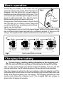
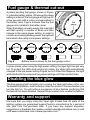
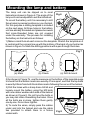
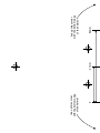
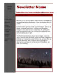
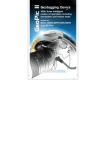
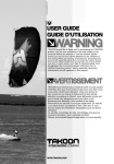
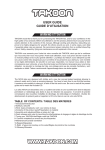
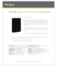
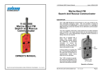
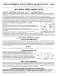
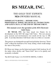
High performance caving light system
User’s Manual
En
For your safety
To prevent damage to your Viper light or injury to yourself or others, read the
following safety information in its entirety before using this equipment. Keep
these instructions where all those who use the product will read them.
! Observe proper precautions when handling batteries. If lithium
ion batteries are misused they may catch fire or explode. Be sure to
observe the following precautions:
- Never leave the battery charging when no one is around.
- Only use the supplied charger to charge the battery.
- Only use the supplied charger indoors.
- Use only batteries approved for use with this product.
- Do not short or disassemble the battery.
- Do not expose the battery to flame or excessive heat.
- Regularly check the battery casing for damage.
- Always disconnect the battery when not in use.
! Do not disassemble. Touching the internal parts of the product could
result in an injury. In the event of a malfunction the product should be
repaired only by a qualified technician. Should the product break open
as the result of an accident, disconnect the battery immediately. The
warranty will be void if the product has been opened at any time.
Unplug
immediately in the event of a malfunction. If you notice
!
smoke or an unusual smell coming from the product or from the AC
adaptor, unplug the adaptor and/or disconnect the battery pack
immediately. Continued operation could result in an injury.
! Keep out of reach of children. The product is not suitable for use by
children under 14 years of age.
Avoid
looking directly into the light. The light output of the product
!
can be extremely high. Shining the light directly into your eyes or
another persons eyes could result in an injury.
In the box
Before reading the rest of this manual, please ensure that there are no items
missing from the box. If any items are missing please contact the retailer you
purchased the product from immediately.
1 x Viper lamp unit
1 x Car charger adaptor
1 x Viper battery unit
3 x M3 mounting bolts
1 x Smart charger
6 x Rubber washers
1 x UK mains adaptor
2 x Cable ties
Introduction
Thank you for your purchase of a Viper high performance caving light system.
This manual has been written to help you enjoy using your Viper light. Read
this manual completely before using the product.
The Viper light was designed by Custom Idea Ltd to be a no-compromise high
performance caving light utilising the latest LED and battery technology.
During its development, the product was tested exhaustively by Warmbac
Wetsuits, a specialist caving company in Somerset, and by numerous caving
enthusiasts in the Mendip hills of the UK. The product you have purchased is
the result of continued refinement during this process of testing and
development.
High quality precision CNC machining is used throughout and the unit is fully
sealed against immersion in water. With four power settings and a patent
pending fuel gauge indicator, the Viper light represents the cutting edge of the
caving light market.
825 lumen output
Four light settings
Lasts up to two days
Lithium-ion battery
Integral fuel gauge
Fully immersible
CNC machined
Upgradable LEDs
Designed in the UK
Connecting and disconnecting
The Viper connectors are industrial quality sealed connectors which operate
with a push click locking action to prevent accidental disconnection. They are
polarised to ensure that they only connect the correct way around.
To connect, line up the white arrows as shown in Figure 1 and push together
until you hear a click. To disconnect, pull the sleeve back to release the locking
mechanism and disconnect the connectors, as shown in Figure 2.
Fig 1
line up
arrows
Fig 2
pull sleeve
back to disconnect
Basic operation
Connecting the battery to the lamp unit will
power the electronics inside. When the Viper is
plugged in but the light is off, you will notice a
regular blue glow at the bottom of the lens. This
is to remind you that although the light is off, the
power is still connected. You should always
disconnect the lamp unit when not in use.
A long press of the button shown in Figure 3 will
turn the light on or off and a short press will
cycle through the four available power settings:
camp, low, mid and high.
Fig 3
on/off
and mode
button
The Viper always turns on set to the lowest power setting. Each power setting
has a different light output and lasts for a different amount of time on a full
charge. The approximate outputs and durations are shown in Figure 4.
camp
low
mid
high
80 lumens
2+ days
215 lumens
12½ hours
365 lumens
5½ hours
825 lumens
1¾ hours
Fig 4
Light output and run times
Charging the battery
To avoid injury, read the safety information at the beginning of
! this manual before handling or attempting to charge the battery.
Only use the smart charger provided to charge the battery. You may use the
charger with either the UK mains adaptor or the car adaptor lead provided.
Plug the charger into either the UK mains adaptor or the car adaptor lead. The
red power light should come on and the charging light should flash red three
times. Now plug the battery into the charger. The charging light will be lit red
continuously during the charging cycle. The charging light will change to
green when charging is complete.
Fuel gauge & thermal cut-out
A patent pending fuel gauge, shown in Figure
5, indicates battery status. Whenever the camp
setting is entered, the fuel gauge will light up for
a few seconds with a colour corresponding to
the battery level. Figure 6 shows how the fuel
gauge colour relates to the battery level .
When the battery is nearly empty, the main light
will flash quickly a number of times and then
change to the camp power setting. In order to
conserve remaining battery power, the light will
be limited to the camp or low power settings .
green
Fig 6
yellow
orange
fuel
gauge
Fig 5
red
red
flash
Battery level is shown by the fuel gauge colour .
In some cases, when using the high power setting, the Viper light can get very
hot. To protect the LEDs and electronics inside, the Viper light automatically
changes to the low power setting if it gets too hot. When this happens, the light
will be limited to the camp and low power settings until it has cooled down.
Disabling the blue glow
The blue glowing light reminds you to unplug the Viper light when not in use.
To disable this feature, hold the button down for around 15 seconds when you
turn the light on. You will notice a succession of blue flashes confirming that
the feature has been disabled. Repeat this procedure to re-enable the feature.
Warranty and support
We hope that you enjoy using the Viper light trouble free. All parts of the
lighting system are guaranteed against faults in manufacture for a period of
one year from the purchase date. If you have any support enquiries,
suggestions or feedback then please contact [email protected] or visit
us at www.customidea.com or www.vipercave.com.
Mounting the lamp and battery
The lamp unit can be clipped on to most
helmets as shown in Figure 6. The angle of the Fig 6
lamp unit can be adjusted to suit the individual.
To mount the battery unit it is necessary to drill
three holes in precise locations on your helmet.
For this purpose a drilling template is included
on the next page. All three holes in the battery
unit are already threaded and please be aware
that cross-threaded holes are not covered
under the warranty. The process for installing
the battery on the helmet is as follows:
1) Make a small hole at each cross on the template. Stretch the template so it
is central and the corners line up with the bottom of the back of your helmet as
shown in Figure 7a. Mark the drilling positions with a pen through the holes.
82m
0
m
line up this corner
with the bottom edge
of the helmet
82m
m
Fig 7
line up this corner
with the bottom edge
of the helmet
41mm
82mm
(a) Mark
41mm
(b) Check
(c) Drill & mount
2) As shown in Figure 7b, use the measure on the bottom of the template page
to check that the bottom marks are exactly 41mm apart, and that the top mark
is exactly 82mm from both the bottom marks following the curve of the helmet.
3) Drill the holes with a sharp 5mm drill bit and
loosely mount the battery using the M3 bolts
with one rubber washer each side of the helmet
as shown in Figure 8. Do not force the bolts or
you may risk cross-threadding the holes. Once
all the bolts are in place, tighten them gently
one by one. Do not over-tighten.
5) To route the wires, simply pass the cables
under and into the helmet and use the cable
ties provided to attach them to a fixture
underneath.
Fig 8
0
line up this corner
with the bottom edge
of the helmet
41mm
82mm
line up this corner
with the bottom edge
of the helmet
CUSTOM IDEA LTD
http://www.vipercave.com
http://www.customidea.com