1
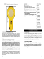
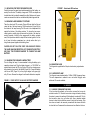
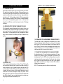
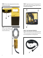
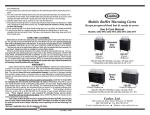
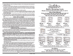
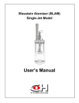
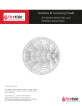
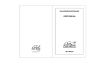
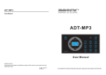
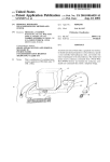
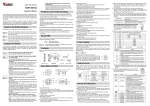
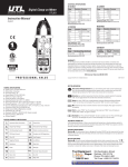
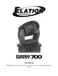
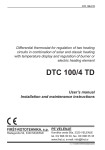
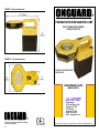
FIGURE 9. Side view dimensions
®
PORTABLE INSPECTION MAGNIFYING LAMP
12VDC POWERED WITH EXTENDED
2 HOUR BATTERY LIFE
FIGURE 10. Top view dimensions
STANDARD 2.25 MAGNIFICATION
5 DIOPTER LENS
USER OPERATING GUIDE
MODEL 2020-38
Administrative:
810 Russell Palmer Road
Kingwood, TX 77339
P.O. Box 6092
Kingwood, TX 77325
Phone: 281-359-1519
Email: [email protected]
®
ONGUARD IS A REGISTERED TRADE NAME AND TRADE MARK
FOR ALLESTEC CORPORATION
12
© 2012 Allestec Corporation. All Rights Reserved. 2020-38-2570A-EM-090612 USA
CAUTIONS
Read the User’s Manual Before Using
Do not use while driving.
Do not drop or throw magnifier lamp.
Always charge lamp battery in a dry location.
Keep dirt off of lens to keep it from scratching.
Do not operate the lamp without the clear fluorescent light shield.
Do not immerse this magnifier in water. This unit is not waterproof.
Keep children away from the magnifier lamp. This product is not a toy.
Keep sharp objects away from lens – it is Ploycarbonate and can scratch.
Never look directly into the lamp or shine the light into another person’s eyes.
Replace bulb or batteries with type indicated in Specifications in the User’s
Manual.
Do not crush, cut, pull or expose charging adapter cords to extreme heat or
sharp edges.
Position charge adapter cords so that they do not become entangled or become a safety hazard.
Do not substitute power cords or charging adapters. Only charge batteries
with supplied wall outlet AC adapter.
RISK OF FIRE OR INJURY TO PERSONS. CHARGE ONLY WITH
ORIGINALLY SUPPLIED BATTERY CHARGER.
WARNINGS
Keep combustibles away from magnifier lens – extreme heat can cause fires.
Contains non-spill sealed lead acid batteries. Batteries must be recycled or
disposed of properly.
DO NOT dispose of batteries in fire, as this may result in an explosion.
DO NOT open battery or short circuit, this may cause the battery to leak or
get causing personal injury. Go online to locate nearest battery disposal facility.
Keep plastic packing bags away from children. Choking hazard.
Lamp bulb contains Mercury. Dispose of properly per local and state laws.
2
3.4 REPLACING THE BATTERY
Turn off the lamp. Remove the lamp handle assembly as well as the DC
cigarette light cord. Remove the retaining screw (Figure 5B) at the rear
inside edge of the battery compartment. Remove the battery retainer
and then disconnect the two wires at the battery terminal. Carefully remove the battery and discard it in accordance with local laws. Insert the
new battery observing the polarity markings on the inside edge of the
battery compartment. Reinstall the terminal strips and then the battery
retainer. Charge the new battery prior to utilizing.
4.0 SPECIFICATIONS and REPLACEMENT PARTS
Battery: 3.4 AH, 12VDC gel cell. P/N 20202707.
Battery life: Minimum 2 hours with fully charged battery at ambient 72
deg. F (22 deg. C), continuous at sea level.
Lamp: Included in unit - 18 Watt, 5100K cool white color temperature.
P/N 20202623. Warm white P/N 20202047.
Standard Lens: Hard coated polycarbonate, 3.8” (96mm) viewing diameter. 5 diopter, 2.25 magnification. P/N 20202581. Suggested distance from subject to center of lens utilizing 5 diopter: ~4.5 inches
(114mm).
Fluorescent lamp is 18 watts, Circline T6 brand.
Nominal operating temperature: 0 deg F (32 deg. C) to 120 deg. F (48
deg. C).
Total weight: 5.63lbs (2.55kg).
12VDC Charger P/N 20202241 ● Car battery power cord P/N 20202704
● Internal battery power connector P/N 20202698.
5.0 LIMITED WARRANTY
Allestec Corporation will provide warranty for the 2020-38 lamp for a
period of three months. Allestec agrees to repair or replace any component or subassembly it deems necessary to fulfill the obligation of the
warranty. The warranty does not cover abuse to the unit, mechanical or
electrical. Also not covered under the warranty is water, chemical, particle or humidity damage, acts of God, lightning and other external, unknown influences. Warranty is void if any protected, secured screw
bond has been broken. The warranty does not cover the battery. Since
different battery manufactures are utilized, the user must contact the
battery provider as indicated on the battery itself. The warranty does not
cover the fluorescent bulb. To service the unit, send the magnifier lamp
to Allestec and provide a contact name with a phone number. State the
nature of the problem, if known. Allestec has the right to refuse warranty if the product has demonstrated user abuse or neglect.
11
FIGURE 8. Top view indicating lens retaining screws.
FEATURES
APPLICATIONS
Portable operation
Nature
Interchangeable diopter lens
Biology
Interchangeable color temperature lamps
Medical
High quality polycarbonate case construction
Schools
Large battery for over two hours of continuous
Hobbies
operation
Intense illumination on objects for the most deScientific
manding applications
Forensics
Compartment for storing extension cord to allow
Pathology
8’ extension connection to a 12VDC car recepChemistry
tacle
Laboratory
Electronics
Inspections
Archeology
Universities
Dermatology
Manufacturing
Quality Control
1.0 PRELIMINARY PROCEDURES
3.2 REPLACING THE MAGNIFYING LENS
Refer to figure 8A and remove the four flat head screws. Take the top
lens retainer off then remove the lens. Carefully locate replacement
lens into the guide, replace the lens retainer. When tightening down the
screws, first screw them down till just taught, then cross tighten each
screw.
3.3 REPLACING OR EXCHANGING THE LAMP
Overtime, the glass edges of the fluorescent lamp, on each side of the
electrical connector start to discolor. When the discolored area shows a
beadlike appearances the lamp should be replaced. Remove the lamp
handle assembly from the battery compartment. Wear protective goggles for this installation procedure. Unplug the DC cord connecting into
the bottom of the handle assembly. Remove the three screws on the
side of the clear lamp cover (Figure 3B). Carefully remove the lamp
from the reflector ring. Slowly pry off the 4-connector wire assembly
from the pins of the lamp base. Reinstall the connector to the new lamp
(do not allow pressure on lamp glass area) and then place the lamp into
the retaining ring. Verify the lamp electrical connector is placed correctly on the 4 lugs. Reinstall the clear lamp cover verifying the 4 lug
pins are visible.
10
1.1 INTRODUCTION
The Allestec Onguard magnifying lamp is designed to be utilized in
commercial and industrial applications. The application of an abundant,
even amount of light energy provided by the Onguard reveals the most
intricate structure of any specimen. The inspection lamp has the convenience of portable, continuous operation for up to 2 hours.
1.2 OPERATING STATEMENT
Read this manual thoroughly prior to utilizing the Onguard magnifying
lamp. Read the warning signs located on the bottom of the lamp housing prior to operating. Do not use this lamp inconsistent to the applications it is designed for.
3
1.3 UNPACKING CONTENTS FROM SHIPPING BOX
Carefully remove the upper lamp-handle assembly and the battery assembly from the box. The battery charger and 12VDC car adapter are
located below the lens handle assembly box flap. Make sure all components are removed from the box and discard the plastic bags and ties.
FIGURE 7. Switch and LED functions
1.4 ENGAGING LAMP ASSEMBLY TOGETHER
Take the coiled cord DC connector (Figure 4B) and slide the flat part
under the tab of the lamp housing. Plug the connector (Figure 4A) into
the bottom of the lamp housing. Coil the cord in the compartment flat
against the bottom of the battery retainer. To clamp the two components together, carefully align the cams at the bottom of the lamp assembly (opposite of latch) so they engage with the battery compartment, then push down handle to snap the two halves together. It is better to have the battery compartment on a sturdy surface than try to
bring the two pieces together while holding them.
CAUTION: DO NOT PLUG THE 12VDC CAR AUXILIARY CORD IN
THE LAMP CHARGING RECEPTACLE TO CHARGE THE BATTERY.
USE ONLY THE PROVIDED CHARGER TO CHARGE THE LAMP
BATTERY.
1.5 CHARGING THE ONGUARD LAMP BATTERY
Prior to utilizing the lamp, it is recommended to bring the battery up to
operating charge level. Plug the battery charger in a 115-230VAC receptacle and connect the DC plug (Figure 1B) into the charging receptacle located in the back of the handle (Figure 2A). Charge the battery
until the red LED (Figure 1A) on the plug-in charger turns green, typically 12 hours. Remove the charger from the wall outlet when complete.
FIGURE 1. 12VDC OUTPUT 100-240 VAC BATTERY CHARGER
2.4 MAGNIFYING LENS
The Onguard is supplied with a 5 diopter hard coated, polycarbonate
lens.
2.5 FLUORESCENT LAMP
The Onguard comes standard with a 18 Watt, 5100K fluorescent lamp.
This color temperature is referred to as a cool white. Daylight, warm
white and UV are also available.
3.0 SERVICE
3.1 CLEANING THE MAGNIFYING LENS
If the lens has dirt sediment on the surface, remove the lens as described in section 3.2. Rinse the lens under running cold water, allowing
the water to remove the sediment till all sediment is washed off. Pat dry
the lens with a clean, dry, soft cotton cloth. Use a standard window
cleaner to clean the lens and then secure it back into the housing. If the
lens does not need to be removed, proceed with the cleaner and cloth
to clean the lens. Commercial lens cleaners can be utilized on the lens.
4
9
2.0 OPERATIONAL PROCEDURES
FIGURE 2. 12VDC CHARGING RECEPTACLE
2.1 OPERATING THE LAMP
Depress the ON switch located on the top, left hand side of the handle.
The switch to the right will turn off the lamp. The lamp will stay on continuously during the length of the battery level. When the battery cannot
sustain a consistent luminous intensity for the lamp, Onguard will automatically turn off. The three battery indicator LED’s give approximate
status of remaining charge left. When the battery is mostly discharged,
there may not be enough starting power to turn on the lamp even
though the red LED was on when the lamp was turned off. Recharge
the battery.
2.2 VIEWING OBJECTS THROUGH THE MAGNIFYING LENS
With the magnifier assembly disengaged from the battery holder, move
the assembly close or away from the object of observance until the image is crisp clear. Keep the lamp parallel to the observation surface to
avoid distortion. The lamp assembly by itself (disengaged from battery
pack) or when connected to the battery pack may be operated in any
position.
1.6 DISENGAGING THE LAMP ASSEMBLY FROM BATTERY BOX
The lamp upper housing is designed to be separated from the lower
battery compartment (clamshell design) by pressing the disengaging
latch (Figure 3A). Push the button located on the battery case with
thumb (Figure 3), raise the handle to disengage lamp assembly from
battery. The lamp can now be maneuvered within the proximity to the
observing subject with the power cord line attached.
2.3 BATTERY LIFE
Under normal operating temperature conditions, 72 deg. F (22 deg. C),
sea level altitude, battery less than 3 years old, the battery will last for 2
hours continuously. Figure 7A shows the green, yellow and red LED’s
to indicate battery life. Each LED represents approximately 40 minutes
of battery life when the battery is fully charged. Batteries that are not
utilized still lose a certain percentage of charge every month. As the
battery ages over the years, the 40 minute increments will diminish with
time. When utilizing the lamp, once the battery drains to a certain operating voltage, the lamp will automatically turn off.
8
1.7 CONNECTING THE ONGUARD TO CAR AUXILIARY POWER
As indicated in section 1.6, open the battery compartment of the lamp.
Unplug the DC connector (Figure 4) connected to the bottom of the
lamp assembly. Take the 12VDC coiled cord (Figure 6) and connect the
small connector to the same receptacle. Run the cord under retaining
tab of Figure 4B. Connect the other end of the cord to a car cigarette
lighter. When connected to a car battery, the status LED’s continue to
indicate battery voltage level.
NOTE: The car battery cannot be utilized to charge the lamp.
5
FIGURE 3. Side view of lamp showing release latch (A) and retaining
screws (B) to remove lamp guard.
FIGURE 4. Upper lamp ballast assembly removed showing 12VDC power
connection into bottom of lamp.
6
FIGURE 5. Image showing the upper half of the lamp removed. The
plug (A) needs to be inserted into the receptacle (Figure 4A) when the
unit is removed from the shipping box.
FIGURE 6. 12VDC CAR AUXILIARY POWER CORD
Unplug the connector (Figure 4A) from the lamp base then plug the
12VDC car cord (Figure 6A) into the same receptacle. Plug the other
end of this cord (Figure 6B) into a car auxiliary power outlet.
7