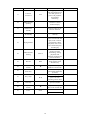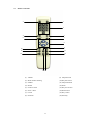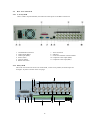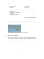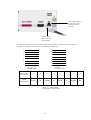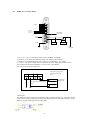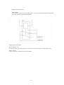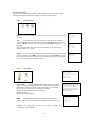
1
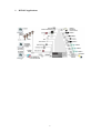
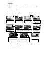
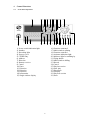
The Range of Digital Video Recorders
The MPEG 4 Digital Video Recorder
With three different models in the DVR365 range there’s a DVR for every
application.
Choose the 4-way DVR for those small but demanding CCTV installations, or the 8way DVR will suit most businesses requirements, for the large CCTV installations
choose the 16-way DVR.
The DVR365 will allow you to record video and sound in real time on every channel.
The DVR also acts as a “video server”so you can now keep an eye on your property
from anywhere in the world by logging onto the DVR via the Internet.
Whether you use the DVR365 for simple unattended automatic recording of camera
pictures in a small corner shop or you monitor the live activity of high street stores
worldwide, the DVR365 really is a fantastic all-round product.
VERSION 003/OCT2005
1
Operational Precautions ........................................................................ 4
1.1 Accessories Check List .................................................................................. 4
2
Product Features And Specifications .................................................... 5
2.1 Product Features ............................................................................................ 5
2.2 Specification Table ........................................................................................ 6
3
Installation ............................................................................................. 7
3.1 Hard Disc Drive Installation .......................................................................... 7
4
Control Functions .................................................................................. 8
4.1 Front Panel Operation.................................................................................... 8
4.2 Schedule of Key Functions ............................................................................ 9
4.3 Remote Controller ........................................................................................11
4.4 Rear View of the DVR..................................................................................12
4.5 Ethernet LAN port connection ......................................................................13
4.6 RS485 Port (4 / 8 Way DVR) ........................................................................15
5
System operation...................................................................................17
5.1 Start/Stop the recorder ..................................................................................17
5.2 Recording operation .....................................................................................17
5.3 Alarm output ................................................................................................18
5.4 Pan-tilt control operation ..............................................................................18
6
Networking............................................................................................20
6.1 Direct Connection.........................................................................................20
6.2 Local Area Network......................................................................................20
6.3 Internet Connection ......................................................................................20
7
Front panel and remote controller operation ......................................25
7.1 Operation Menu Introduction........................................................................25
7.2 Menu option schedule...................................................................................26
8
Functional Operation............................................................................30
8.1 Recording.......................................................................................................30
8.2 Playback .......................................................................................................30
8.3 Playback fast play.........................................................................................30
8.4 Playback slow play .......................................................................................31
8.5 Control of PTZ equipment ............................................................................31
8.6 Menu operation.............................................................................................32
8.7 Playback of CDROM....................................................................................38
9
Operation via a Network ......................................................................39
9.1 Using the client software ..............................................................................39
9.2 Operation using the Web software.................................................................40
10
A guide to giving your PC an IP number..............................................45
11
Frequently Asked Questions.................................................................48
Appendix A(1)
Recording Times at LOW Resolution ..................................50
Appendix A(2)
Recording Times at MEDIUM Resolution ..........................51
Appendix A(3)
Recording Times at HIGH Resolution.................................52
Appendix B Example on how to setup SCHEDULE recording .......................53
2
1.
DVR365 Applications
3
1 Operational Precautions
l
l
l
l
l
l
l
l
l
l
l
l
l
l
l
l
l
1.1
All the safety and operating instructions should be read before the DVR365 is operated.
All the safety and operating instructions should be retained for future reference.
Ensure all operating instruction and warning notes are complied with at all times.
Do not use strong or abrasive detergents when cleaning the DVR365.
There are no user-serviceable parts inside. Please contact a qualified engineer for servicing
Do not expose the DVR365 to water or moisture and do not try to operate it in wet areas.
Please make sure that both ends of the power lead are plugged in.
Do not drop foreign objects through the DVR365’s case or expose it to moisture.
Do not attempt to disassemble the DVR365.
Contact a qualified engineer if the following situation happens:
Ÿ The power lead or plug is damaged.
Ÿ The DVR365 has been exposed to rain or water.
Ÿ The DVR365 does not operate normally by following the operating instructions.
Ÿ The DVR365 falls to the ground or its cover is damaged.
When replacement parts are required, make sure that the service engineer has used replacement
parts specified by System Q Ltd or that these parts have the same characteristics as the original
ones. Unauthorised substitutions may result in fire, electric shock, or other hazards.
Use only with a mounting accessory recommended by System Q Ltd.
Never push objects of any kind into the case of the DVR365 as they may touch dangerous voltage
points or short cut parts that could result in a fire or electric shock.
If an outside cable system is connected to the DVR365, be sure that the cable system is grounded
so as to provide some protection against voltage surges and built-in static charges. It is
recommended that this unit is connected to a power surge protection unit.
All normal precautions to avoid component damage due to electrostatic discharge should be taken
during installation and operation.
To prevent electric shock, do not remove screws or the unit’s cover.
Do not cover the radiator fan
Accessories Check List
1.
One Power Cable
2.
One Remote Controller
3.
Four HDD Data Cables
4.
One Standard Cat 5 Network Patch Lead
5.
One Packet Of Installation Fixings
6.
One CD For Installation of the Client software and the Player
7.
One User Manual
8.
Audio Leads (with the 16-Way DVR)
9.
One Crossover Lead
4
2
Product Features And Specifications
2.1
Product Features
•
Real-time Monitor
There are two video outputs:
1) Composite video output, for use on a standard CCTV monitor (BNC)
2) VGA output port, for displaying the DVR’s output on a PC monitor
Both outputs can display single or multiple channels
• Storage
The DVR has space internally that allows you to install up to eight large capacity hard disk
drives (HDD). If you wish to install an internal CD writer this will take up two drive spaces.
The DVR software allows you to decide what to do when the hard disk(s) is full i.e. stop
recording or start overwriting the oldest data first.
• Back-up
There are various ways in which you can back up records that are stored on the DVR to an
external device:
The unit comes with a Universal Serial Bus (USB) port for connecting external backup
devices such as HDD & Caddy, a USB CDROM Writer (CD-RW) and a USB memory stick.
Note that some USB memory sticks are not compatible with this unit.
The DVR also has the ability to control an internal CR-RW, which means you can fit CD-RW
in the DVR itself.
You can also connect the DVR to a Local Area Network (using a standard network cable) or
directly to another PC (using a network crossover lead), for downloading data to your
computer.
• Record & Playback Mode
The DVR has a built in multiplexer which allows you to view all the cameras simultaneously
on the monitor, you can also view individual cameras at the same quality as when in multi
screen mode i.e. the images are not digitally enhanced.
There are various different recording modes that you can set: Manual recording i.e. you control the recording manually by turning it on/off as and when you
want.
Timed recording i.e. you can set the DVR to record and stop for given times during the day
e.g. 09.00AM to 05.00PM.
Event recording i.e. the unit will start to record when it has been triggered, this is a good way
to preserve hard disc space. When the DVR is set for alarm / motion recording it will record
the previous four seconds to the alarm being activated.
The DVR supports triplex operation i.e. you can view live images whilst recording, searching,
playing back (on one channel) and transmitting over a network.
The DVR offers multiple playback modes: X2, X4, X8 fast play, stop, 15F/S, 5F/S slow play
and frame-by-frame playback.
•
Alarm Input
The DVR has eight external alarm inputs that allow devices such as PIR’s, doorbell, door
contacts etc to start the DVR recording.
The DVR has a built in protection circuit for Alarm input and output.
•
Pan Tilt & Zoom Control
The DVR can control pan-tilt-zoom equipment using its RS485 communication port. It also
allows you to control various protocols for different PTZ equipment connected to the unit.
•
Communication connection port
RS232 port supports a standard dial up Modem connection, keyboard for central control, or
connection to a computer via serial port for system upgrading.
Standard Ethernet port for remote connection and control. Connect the DVR to a router using
this port for connection to the Internet (ADSL)
5
2.2
Specification Table
Parameter
Processor
Operation system
Model
Video input
Video output
Audio input
Audio output
Video display
Video standard
System resource
Image resolution
Motion detection
Video compression
Audio compression
Image compression
rate
Video recording
speed
Image quality
Hard disc
Alarm input
Alarm output
Alarm relay
MODEM
connection
Network
connection
Pan-tilt control
Power
Power
consumption
Working
temperature
Size
4 Channel
8 Channel
16 Channel
AMD ELANSC520/133 embedded microprocessor
Real-time operation system (RTOS)
CCT723
CCT726
CCT727
4 Channel (PAL) BNC
8 Channel (PAL) BNC
16 Channel (PAL)
1.0VPk- Pk 75
1.0VPk- Pk 75
BNC 1.0VPk- Pk 75
1 Channel PAL BNC (1.0VP- P 75 ) video signal
1 channel VGA output port
4 Channel 2008 Channel 20016 Channel 2001000mv10K (BNC)
1000mv10K (BNC)
1000mv10K (RCA)
1 Channel 2000mv
8 Channel 20016 Channel 2001K (RCA)
1000mv10K (RCA)
1000mv10K (RCA)
1&4 window display
1,4,9 window display
1&16 window Display
PAL - 625 line, 50f/s
Real-time recording, one channel playback and network operation
simultaneously (Triplex Operation)
Real-time monitor 704×576, playback 352×288, VGA output 720×576
Area setting: 396 detection areas on the screen; 3 different sensitivity levels:
Low, Medium & High
MPEG-4 CBR (fixed frame rate); MPEG-4 VBR (variable frame rate)
Audio: ADPCM 28.8Mbyte/hour; G.729: 3.6Mbyte/hour; Video: 40460Mbyte/hour
352×288CIF format; 176×144QCIF format; 704×576 4CIF format
Real-time mode: PAL 1fs-25f/s per channel
6 selectable levels
Inside equipped with 4 IDE ports, enabling you to install 8 internal HDDs
8 channel voltage alarm input (+5 - +15V DC. Needed for the alarm input)
3 output channels (output in open/close contact or controllable 12V output)
30VDC 1A, 125VAC 0.5A (relay output)
RS232 (Serial Port)
RJ45 10Mb Ethernet connection
RS485 (4 / 8 Way DVR) A B Connection Terminal (16 Way DVR)
230VAC
60W
70W
80W
-10°C - +55°C
441 (Width) x430 (depth) x89mm (height)
6
3
Installation
3.1
Hard Disc Drive Installation
The DVR is supplied without HDDs installed, thus one should be fitted before operating the
DVR. The maximum HDDs that can be installed internally is eight 400Gb sized drives.
Note: .If you install an internal CD-RW or a removable HDD, you will only be able to install
five or six internal HDDs.
3.1.1 Installation Steps
Note: The CCT723, CCT726 and CCT727 are supplied with silver cases.
1
3
2
1. Remove the outer case
of the DVR
2. Remove the HDD
bracket from inside the
unit
3. Separate the top and
bottom part of the bracket
4
4. Install the HDD. Note
the HDD is installed
upside down, ensuring
bracket is in correct
5
6b
6a
5. Screw the two bracket
parts together.
6. Set jumper/slave settings on the HDD. The master HDD is
connected to the end of the IDE data cable; the slave is
connected to the middle connector.
7
7. Fix the HDD
bracket into the unit.
8
10
9
4
8. Connect HDD data cable to
IDE port ensuring the first
connection is used first i.e. IDE1
for first master/slave HDD, the
IDE2 for second master/slave etc.
9. Connect power cable to the
HDD. Tip. Look for the red
cable on the power and the red
cable on the data bus; when
connected correctly these two
cables reside next to each other.
10. Replace the cover.
Note. The jumper settings will be given by the HDD manufacturer. Most
manufacturers’settings vary.
7
4
4.1
Control Functions
Front Panel Operation
5
2
3
4
7
6
9 10 12
8
11
1
15 13 17 18 19
14
20
16 22 23 24 25 26
21
27
28
29
30
16) Function assistant 2
17) Multi-window splitting
18) Function assistant 1
19) Assistant indication light
20) Indicator light for standing by
21) Flying shuttle
22) Multi-window shifting
23) Record
24) Cancel
25) Play last section
26) Slow play
27) Play/pause
28) Fast play
29) Play next section
30) Enter
1) Power switch/indication light
2) Number
3) Recording light
4) Perspex cover
5) CD-RW Bay
6) Address
7) Direction
8) Remote receiver
9) Cancel
10) Enter
11) Direction
12) Direction
13) Direction
14) Information
15) Single window display
8
4.2
Schedule of Key Functions
Order
Key Name
Logo
Function
Comments
1
Power switch
and indication
light
Power
Power Switch
Indication Light
Power off by
pressing the key for
4secs
2
Numbers
1 2 3… . 16
Password input,
window shift or
number input
As number input,10
is equal to 0
3
Recording
Light
Red on numbers
If the light is red, that
channel is being
recorded
4
Perspex Cover
Black Plastic
Dust protection
5
CD-RW
CD-RW
Backup records
6
Address
ADD
Input remote control
address for operation
of DVR
t u
Transverse moving;
shifting level 1 and
level 2 menu; pan-tilt
control
pq
Lengthways moving;
change set-up; change
number; pan tilt
control
7, 13
Left Right
11, 12
Up down
8
Remote
receiver
Used to receive the
remote signal
Cancel
9, 24
Cancel
ESC
10
Enter
ENTER
14
Information
INFO
15
Single window
display
During playback,
restore to real-time
monitor
Enter
Enter main menu
Press to show the
system information
Shift the window to
single window
In single window
mode
Press the Function
Key to display the
pan-tilt control
16
Function
assistant 1
Used for setting
Motion Detection
areas
Fn1
During playback,
displays the playback
status bar
9
During playback use
with the number key to
start PIP (picture in
picture) for playback
and realtime
monitoring
17
Function
assistant 2
18
Multi-window
splitting
During monitoring
switch to a multiwindow display
19
Assistant
indicator for
standby
Indicator light for the
function assistant
20
Indicator light
for standby
Light on when DVR in
stand by
Flying Shuttle
Directional control:
outer circle for left and
right, inner circle for
up and down; When
playback, outer circle
can control back play
and fast play
21
Fn2
22
Multi-window
shifting
MULT
23
Record
REC
25
Play last
section
9
26
Slow Play
27
Play / Stop
„/;
28
Fast Play
8
29
Play next
section
:
30
Enter
Enter
Multi-window shifting
during real-time
monitoring; during
playback, shift
between playback and
monitor window
Start/stop recording,
apply together with
direction key
Play the recording file
before the current file
3 levels of slow play
speed(15f/S,5f/S,frame
by frame)
Play/stop
When in monitor,
press it to enter
recording search menu
3 levels of fast play
speed,X2,X4,X8
Play the recording file
next to the current file
Enter
Enter main menu
10
4.3
Remote Controller
2
1
3
4
5
6
7
8
10
9
13
11
14
16
15 12
(1) Address
(9) Jump forwards
(2) Multi-window shifting
(10) Play last section
(3) Number
(11) Jump backwards
(4) Record
(12) Pause
(5) Function assist
(13) Play next section
(6) Enter / menu
(14) Slow motion
(7) Cancel
(15) Play / Pause
(8) Direction
(16) Fast Play
11
4.4
Rear View of the DVR
4.4.1 4 / 8 Way DVR
On the 4 and 8 way DVR models, the audio and video inputs are all BNC connections.
1
2
3
4
5
6
7
8
9
10
11
Alarm-RS485 connection
Audio output (BNC)
Audio input (BNC)
Power switch
230VAC Mains
RS232 connection
VGA connection
USB port
Local Area Network connection RJ45
Composite Video output (BNC)
Composite Video input (BNC)
4.4.2 16Way DVR
Due to the size restrictions on the rear of the DVR , on the 16 way model, the audio inputs are
through a ‘fly lead’as shown on the next page.
14
17
16 15
7 8 9 1011
1
2
3
12
4
5
13
12
6
1.
VGA Connection
10. Ground (0V)
2.
USB port
11. Ground (0V)
3.
IEEE 1394 (Fire wire) port
12. PTZ Control Inputs (A an B)
4.
Local Area Connection RJ45
5.
Alarm Inputs
13. Composite Video Inputs (1, 3, 5, 7, 9,
11, 13,15) - BNC
6.
Alarm Outputs (Normally Open /
Closed)
7.
Controllable +12V output
8.
+12V
9.
+12V
14. Composite Video Inputs (2, 4, 6, 8, 10,
12, 14, 16) - BNC
15. Composite Video Output (to monitor)
- BNC
16. Audio Output (to loud speaker) - BNC
17. Audio Input Port (Via phono leads)
On the 16 way DVR a made up lead is supplied for the audio input port with phone inputs –see
below.
Note: - ensure that you terminate your audio units into phono plugs.
4.5
Ethernet LAN port connection
The DVR can be connected to a local area network (LAN) by utilising the Ethernet connection
port provided on the rear of the unit. The connecting cable should be category 5 cable terminated
into an RJ45 connector (which is the standard for Ethernet LAN’s). If connected to the network
correctly, the indicator light of the RJ45 input port will be on.
Note: When connecting directly to a PC via the Network connection, ensure that a crossover
lead is used, if connecting through a switcher/hub use a standard LAN lead.
13
The indicator light is
on when correctly
connected to the
network
Connect to PC,
switch, router or
net exchanger
Note: Direct connection to PC is possible by bypassing an Ethernet switch, however, one end of
the cable is required to be crossed over. See below for connections.
3
1
2
3
4
6
1
4
5
5
6
7
8
2
7
8
Fig 3.4.1
Straight Cable
Fig 3.4.2
Crossover Cable
CAT 5 Cable
Core Number
1
2
3
4
5
6
7
8
Colour
Representation
WH/OR
OR
WH/GR
B
WH/B
G
WH/BR
BR
Table 1.0 –Core Number
with respect to Core Colour
14
4.6
RS485 Port (4 / 8 Way DVR)
Alarm Input
Alarm 1
|
|
|
|
Alarm 8
Alarm Output
ALARMOUT1
Controllable
+12V output
ALARMOUT2
+12V
output
Earth
Decoder
Decoder
120Ω
suggested
1, 14, 2, 15, 3, 16, 4, 17 connects to alarm input: ALARM1~ALARM8;
5, 18-OUT1, 6, 19-OUT2 two linked normally open output (alarm outputs)
7, 20-OUT3 are two attached inner lines, either pin is controllable +12V output;
8, 9, 21 are +12V power output, able to be taken as the power supply for an alarm sensor;
Pins 10 & 22 are the B line of RS485, 11 & 23 are the A line RS485;
Pins 12, 13, 24 and 25 are earth lines
+12V
GND
Com
Note: Place a link across the
alarm input end and the
power
NC
The connections
at the DRV end
The connection end of the alarm
device
+12V
|
GND
Alarm Input
The DVR has 8 alarm inputs, either normally open or normally closed type. The power for the
alarm sensor can be provided by the DVR (if the DVR powers too many alarm sensors, it may
affect the normal working operation of the DVR).
15
Diagram of the alarm input
Alarm Output
The DVR has two alarm outputs (normally open). In order to avoid overworking the DVR, please
refer to the parameters of the relay being used.
Diagram of the alarm output
The controllable +12V
This can be used for the alarm output; you can also use it to restore power to a smoke alarm sensor.
RS485 A, B line
Used to connect the A and B line for PTZ equipment.
16
5
System operation
5.1
Start/Stop the recorder
5.1.1
Start the recorder.
When starting the DVR ensure that the power indicator on the front is illuminated.
The system performs a self-diagnostic operation on start up.
If the starting time is within the schedule recording time, the system will start recording
automatically. Note: - if there is no HDDs installed, the unit will start and you will be able to
access menus, there will however, be no recording.
5.1.2
Stop the DVR
To turn the DVR off press and hold the power key on the front panel for approximately four
seconds; the unit will power down in the correct manner. Then switch off the machine with the
power button to the rear of the unit.
Note: - Please try to avoid turning the DVR off by removing the mains as this does not allow
the unit shut down correctly which could cause the HDDs to develop faults. Also if an internal
CD writer is installed and the unit is not powered down from the front of the DVR, the DVR
can loose knowledge of the unit and it will be necessary to reset factory defaults. Do not change
date or time or previous recordings may be lost.
5.1.3
Power off recovery
In the event of a power cut when the DVR is in the state of normal/timing/alarm recording, the
recorder will remember what state it is currently in and carry on when the power is returned.
Note that the state indicator light is the same as it was before the power was lost.
Note: If the power is cut in the state of recording, the system will not store the last 5—15
seconds of recordings.
5.1.4
Password
Before you can enter the menu system, you must input a password. There are two levels of
password: - user password and administrator password
User password
666666
Administrator password
888888
The user password limits you to what functions you can use i.e. it allows you to search video
footage, playback and view system information.
The Administrator password gives you access to all of the software e.g. you can change system
settings etc.
5.2
Recording operation
The default recording mode for the DVR is 24hour continuous recording on all channels. The
administrator user can choose the suitable recording mode required. Instructions for the different
recording modes are as follows: (a) Timing recording
Enter the menu, now you can navigate to the Timing and set the timing period for the recording.
Note when you go into the timing menu you will see that Sunday is highlighted, to change each
day you must go to the required day e.g. Monday, highlight it, you will now notice that both
Sunday and Monday are highlighted. To change the times for Monday you must go back to
Sunday and un-highlight it. Once you have changed Monday ensure that you save your settings
before progressing onto Tuesday. This process must be done for each day See Appendix B for
complete details of how to set it up
See details at Menu>System setting>Timing
17
(b) Manual recording
Press “Record”button on the remote controller or “Record”on the front panel
Check the status of each channel in the recording menu; the highlighted channel is the recording
channel.
For recording on the required channel, simply press the related number key to highlight it. Then
press Enter to begin the recording.
To stop recording of a particular channel press the related number key.
Press Cancel or ESC to return
(c) Alarm Recording
Alarm recording allows you to increase the recording time of the DVR, as it will only start
recording when the PIR etc picks up any movement.
Connect the alarm input device to the DVR according to the device connection i.e. Normally
Open or Normally Closed detector.
Set the correct setting in the menu to start Alarm recording. See details at Menu>System
setting>Alarm setting
(d) Video Motion Detection (VMD) recording
Motion detection recording will also increase the recording time of the DVR, as it will only start
the DVR recording when it picks up any movement.
Points to consider when using Video Motion Detection: - It is important to remember that the
DVR’s VMD circuits look for movement in the camera’s picture, therefore if it is so dark that the
camera cannot see any movement nor will the VDM circuits. However, if you were using VMD
in a darkened room as soon as the light is turned on, the VDM would cause the DVR to record, as
the change in light would be seen as movement. When you are using the VDM with external
cameras, sudden changes of bright sunlight to cloud over may cause the VDM circuits to trigger
the DVR. With this in mind outdoor use of VDM needs careful planning.
In order for VDM to trigger the DVR you need to turn off 24 hour recording on the channel that
requires VDM, ensuring that you do this for each day. Now you can turn VMD on.
Set up the required times and required motion detection setting in the menu. See details at
Menu>System setting>Motion detection
5.3
Alarm output
The alarm output can be used to control an external device such as a buzzer to tell the user that
that the unit has been alarmed. Or it allows you to remotely control a floodlight e.g. you could
turn the light on/off from the other side of the world.
The alarm output is directly proportional to the length of the recording time. After an alarm
activation the unit will record for a user defined length of time and the output relay will be
latched for the same period of time. So if the recording is set at 30secs, the alarm output will be
active for 30secs.
See details Menu>System setting>Alarm setting
5.4
Pan-tilt control operation
The DVR365 range allows you to control Pan Tilt & Zoom Equipment. It is possible to control
PTZ equipment from the DVR, using the Remote Controlled Unit provided or you can operate it
over a network connection.
Confirm the correct connection of the PTZ and the decoder then set the correct decoder address.
You should enter the corresponding protocol of the PTZ equipment that you are using, from the
Menu>System setting>Control menu
NONE
PHILIPS
HSCP
YOUL1
PANA-WV
PE5051K
DEMO
SANTACHI
M9500
DH-2
PE5052K
EE
18
KALATEL
X5600
XCY-RC02
V9KRP
INV
DRAGON
MULTI-AD
PANASONIC
SHARP
SDA
WV-CS850
PIH-717
PIH-1016
DSCP2.9
JEC
YAAN
TCSTD-PP
TCSTD-PD
TC-615
HHX2000
BOGA
TUOXIN
JT1641
AD
SAE
SAMSUNG
PELCO-P2
PELCO-P1
PELCO-D1
DH-CC
The above table shows the protocols that are compatible with the DVR.
Confirm the right connection of decoder’s A, B line and the DVR’s 25-pin port’s A, B line
Set the correct setting in the menu.
To have control over the PTZ equipment you need to ensure that the monitor is in single window
mode (with the camera you require displayed). You should now press the function1 key (Fn1),
this gives you the control interface, and if you press it again the next menu will pop up. Use the
direction keys to move the PTZ equipment.
19
6 Networking
The DVR365 can be networked in three different ways; Direct connection, LAN connection or
Internet connection.
6.1
Direct Connection
It is possible to connect the DVR directly to a PC that has a Network Interface Card. It must be
connected to a P.C using a network crossover lead. You must give the DVR an Internet
Protocol (IP) address e.g 192.168.001.108. The subnet mask should be set to 255.255.255.0
Leave the Default Gateway blank. Power down the DVR365 to register the changes. Hold the
front power button for 4 seconds, then switch off at the rear. Now power back on at the rear of the
DVR and then the front.
Now set the PC with a unique I.P address in the same range as the DVR e.g 192.168.001.100
The PC I.P address must not be the same as that entered in the DVR. This can be usually be set
on the PC by clicking START > SETTINGS > NETWORK CONNECTIONS > LOCAL AREA
CONNECTION> PROPERTIES> INTERNET PROTOCOL (TCPIP) and manually setting the
I.P address. The Subnet Mask and Default Gateway must be the same as set in the DVR.
Now load the DVR365 client and player software. Further instructions about this are included
towards the end of the manual. The client software will require the DVR I.P adddress e.g
192.168.001.108, the subnet mask and Gateway as above.
6.2 Local Area Network
You can connect the DVR to a Local Area Network (LAN) using the connection port on the rear
of the DVR. You must use a LAN cable. You must give the DVR an Internet Protocol (IP)
address. This must be unique to your network but in the same range e.g 192.168.001.xxx. The
subnet mask should be set to 255.255.255.0 The Default Gateway should reflect the Router's IP
address.
Now set the PC with a unique I.P address in the same range as the DVR e.g 192.168.001.100
The PC I.P address must not be the same as that entered in the DVR. This can be usually be set
on the PC by clicking START > SETTINGS > NETWORK CONNECTIONS > LOCAL AREA
CONNECTION> PROPERTIES> INTERNET PROTOCOL (TCPIP) and manually setting the
I.P address. The Subnet Mask and Default Gateway must be the same as set in the DVR.
Now load the DVR365 client and player software. The client software will require the DVR I.P
adddress e.g 192.168.001.108, the subnet mask and Gateway as above. In order to confirm the
correct network connection between DVR and computer, you can use the PING command that
comes with Microsoft Windows systems. To access the PING command, follow the sequence
below: Start > Programs > Accessories > Command Prompt
Once Command Prompt is open type (if 192.168.001.108 is the IP address of the DVR): PING
192.168.1.108
If it comes back and says ‘Request Timed Out’then the two devices are not
communicating/connected correctly. This could be due to a bad or incorrect cable connection or
the incorrect IP addresses. If it comes back and says ‘Reply from 192.168.001.108’the two
devices are connected correctly.
6.3 Internet Connection
CHECK LIST –for connecting a DVR365 onto the Internet
You need a broadband (ADSL) internet connection at the site where the DVR is to be installed.
The ADSL connection at the site where the DVR is installed must have a “STATIC IP address”.
This is because the I.P address for Internet use must be unique on the Web.
(Note - you can request a static IP address from most Internet Service Providers (ISP’s), but they
may charge a small fee for this.)
You will need a broadband router/modem at the DVR site. A good one is the Netgear DG834.
At the remote site where your computer will be located you will also need a broadband
connection to ensure that you have a fast connection to your DVR.
TIP - You can’t use a USB type modem connected to a stand alone PC to get the DVR365 connected to the
internet, you must get a router-modem, that allows multiple computers to share the broadband ADSL
connection. USB modems rely on a computer’s operating system to drive them and the DVR365 cannot do
20
the same thing. Once you have got your ADSL Internet connection with a static IP address at your
DVR site, you can progress to installing the DVR.
If the site where the DVR is to be installed already has an ADSL Internet connection that is
shared by one or more computers it is likely to already have an ADSL modem/router of
some description. If this is the case you will have to either configure the existing
modem/router or replace it with a new one. If it’s an existing installation, we strongly
recommend you enlist the help of the person or company that installed and configured it
originally.
The rest of these instructions now refer to installation using the Netgear modem/router.
6.3.1
Step 1 Getting the router-modem connected to the Internet
If you have already done this and can already “surf the internet”you can skip this section and go
straight to step 2.
Your ISP should have given you all the information you need to get your modem and computers
connected to the Internet. You should have the following information;
login user name
password
static IP address
Connect your computer to the Netgear router using the blue STRAIGHT RJ45 cable supplied with the
router. Next, you need to set up the router to connect to the Internet. See the Netgear instructions of how to
do this if you’re not sure, but the basic method is;
1. Run Internet Explorer
2. Type in the router’s address 192.168.000.1 (usual default for a Netgear)
3. Type in the user name “admin”,
4. Type in the password “password”
5. You should now see the Netgear set-up page.
On this page navigate on
the left-hand side to the
“WIZARD”and run this
wizard to set up your
connection. When it asks
you for the password etc
enter them. Obviously the
Netgear modem needs to
be connected to your
ADSL enabled telephone
point.
When you have finished running the wizard you should be able to test your connection and see
live Internet pages on your PC. If you cannot get the Internet connection please run the wizard
again and check you have entered your user name and password correctly. If you still have a
problem at this stage you MUST CONTACT your ISP.
TIP- if you cannot get your computer to connect to the Netgear device, check that your computer
is in the same IP address range as the Netgear. This can be found by navigating from My
Computer > Control Panel > Network Setting >TCP/IP > Properties. If your computer is set up
correctly in the same range as the Netgear router it will look like the following:
21
The Address 192.168.000.XXX means it’s in the same range as other devices that share the same
common address 192.168.000. With just the last 3 digits distinguishing between the various
devices. For most networks - DO NOT CHANGE the subnet mask and leave it as
255.255.255.000
Once connected to the Internet you now need to set up the router so that you can connect to it and
the DVR from anywhere in the world over the Internet.
6.3.2
Step 2 –Setting up your static IP address in the router.
In the router navigate to the “Basic Settings”screen and click on “static IP address”.
Next enter the STATIC IP address given to you by your ISP, look at the following picture as an
example, obviously the IP address in the picture is an example you must enter your own here.
The IP address you enter is the STATIC ADDRESS GIVEN TO YOU BY YOUR ISP.
Once you have entered this, please click the “apply”button at the bottom of the screen to update
the router.
Once you have set up your router to work with a static IP address anyone who types this address
into their web browser will be re-directed to your router from anywhere in the world. The next
task is to make the router “route”this request to the DVR.
22
6.3.3
Step 3 –Make the router “route”external connections to the DVR
There are a few ways to do this but we will show you the quickest and most reliable.
The Netgear router can be set up to forward all external connections to a particular IP address
(equipment) on your local area network, in this case this is the DVR365. The method we are
going to show you uses the DMZ feature of the Netgear router. Some other routers have this
feature so you will have to “tweak”and apply these notes to your router if it’s a different model.
Open the Netgear’s menu marked WAN
Click default DMZ server,
Now enter the IP address of the DVR365 - by default this may be 192.168.000.111 or possibly
192.168.1.111. Whatever IP address you enter here is the IP address you MUST enter in the DVR.
The Netgear router will send all external connections to this IP address.
TIP –On a Netgear router the IP address of the DMZ server may appear greyed out, but you will
be able to enter and amend the last 3 digits of the IP address. If your local area network is not in
the range 192.168.000.xxx, you will need to set up the Netgear router to the appropriate range in
its LAN settings screen.
Once you have set up the router to use a DMZ server and set up the DMZ’s IP address you can
move on to setting up the DVR.
6.3.4
Step 4 –Setting up the DVR
The DVR needs to be connected into the same network as the Netgear router or directly to the
router itself. To connect into the network or directly to the router, use the “straight”grey RJ45
cable supplied with the DVR. (Note when you are connecting the DVR directly to a computer
with no router you need a “crossover cable”.
In the DVR you need to set up its IP address to be the same address as you set the DMZ server to
be in the Netgear router. In this example, both the DVR’s IP address and the DMZ server’s need
to be set up to be 192.168.000.111. Also, you will set up the DVR’s “gateway”to be the Static IP
address of the router this means that it accesses the Internet through this “gateway”. In this
example the DVR’s gateway will be 82.10.189.10
To get into the DVR menu press “enter” followed by the password “888888” if it’s still the
default password
Now navigate to System Settings>Network
In System Setting enter the details as follows;
23
NETWORK
SYSTEM
SETTING
IP
192.168.000.111
SUBNETMASK 255.255.255.000
GATEWAY
82.10.189.001
SERVERPORT 00080
TCP PORT
37777
MONITOR
TCP
PLAYBACK
TCP
SAVE CANCEL
Remember:
IP address = whatever you set the DMZ server to in the router
GATEWAY = the router’s IP address, i.e. your static IP address supplied by your ISP.
SUBNETMASK is that of your local area network = Leave at 255.255.255.000
TIP- we recommend you do not change the subnet mask, as this is the default setting for most
networks.
After you have changed and saved the network settings in the DVR (such as the IP address) you
MUST reboot the DVR for these changes to take effect. Obviously please make sure you save the
settings before you reboot!!
Once rebooted, and if the DVR is connected to the Netgear router you will need to test it from
another broadband connection to make sure it is working correctly.
Whilst we can help with the DVR settings, it is the ISP's responsibility to advise on the setup of
your ADSL connection.
24
7
Front panel and remote controller operation
7.1 Operation Menu Introduction
Operation
step
Enter
main
menu and
level 1
submenu
Enter level
2 submenu
Set
menu
contents
Exit the
current
menu
Button-pressing
order
1,Enter
2,Direction (flying
shuttle)pqut
Instruction
During real-time monitor, press to bring
up the password (default six 6’s or six
8’s), now enter the menu.
Press to shift among the six options
3, Confirm Enter
Enter the selected level 1 submenu
4, Direction
(flying shuttle)
pqut
Press to move and select the level 2
submenu item required
5, Confirm Enter
Enter the selected level 2 submenu
1, Direction
(flying shuttle) u
Select the option to be revised, flashing
means being chosen
2, Direction pq
Press to revise the settings
3, Confirm Enter
Save is flashing, choose to confirm
whether you want to keep the revised
setting.
Direction(flying
shuttle) t
Return to the last option of the current
menu
Cancel ESC
Exit to the last level menu
25
Screen display
Menu
SEARCH
CONTROL SETTING
CH
1
PROTOCOL: PELCO-P
BAUDRATE 9600
ADDR
000
SAVE
SEARCH
CANCEL
7.2 Menu option schedule
Main menu
Menu level 1
RECORD
LIST
SEARCH
ALARM
INFO FILE
INFORMATION
HDD STATE
VERSION
Menu level 2
CH 1
DATE 22-08-2005
TIME 02:20 PM
PLAY START
CH 1
DATE 22-08-2005
TIME 02:20 PM
LIST SEARCH
DATE 22-08-2005
SEARCH START
HDD NUM-0 2
HDD CAP-0 1 6 0 0 8 6M
FREE SPACE 0040832M
FILE START 2005-04-12 19:00:22
FILE END 2005-08-22-14:20:44
INDEX 12
MASTER W- - - - - - SLAVE - - - - - - CDR STATE NO
USB STATE NO
VERSION ID 2.45
ISSUE DATE 07-20-2004
WEB VERSION 1.69
26
Remarks
Use DIRECTION key to perform setting
in menu level 2
See details at 7.3.1
Use DIRECTION key to perform setting
in menu level 2.
See details at 7.3.1
Not able to search motion detection
records.
See details at 7.3.1
Displayed information can only be
referred to; i.e. it is not modifiable
An additional BPS information
display shows current BPS rate.
Main menu
Menu level 2
Menu level 1
GENERAL
SYSTEM
SETTING
SCHEDULE
IMAGE
ALARM
DATE
09 –02 - 2005-09-02
FORMAT MM-DD-YYYY
TIME
13: 16: 57
FORMAT 24H 12H
SAVE
SAVETIME
HDDFULL OVERWRITE STOP
RECORDLEN 15 MIN
REMOTEADDR 008
COMMCTRL NONE
SAVE
CANCEL
CH
1
WEEK S M T W T F S
TIME1 00: 00 –24: 00
STATE ON
TIME2 00: 00 –24: 00
STATE ON
SAVE CANCEL
CH
1
MODE CBR/VBR
VIDEO/AU
FRAMERATE REAL/20FS/15/12/10/8/6-1
BITRATE 1024K/512K/768K/384K/256K/128K
QUALITY 4 (1-6) if Variable Bit Rate Selected
ALARM: OFF ON1/ON2/ON3
VIDEO: SET DEFAULT
TITLE 01 ON
SAVE CANCEL
CH 1
TYPE NC / NO
RECORD 1 2 3 4 5 6 7 8
ALMOUT 1 2 3
DELAY
60 SEC/30SEC/10MIN/5MIN/90SEC
TIME1 00: 00 –24:00 ON
TIME2 00: 00 –24 00 OFF
ALMSVR IP 192.168.000.118 OFF
SAVE
CANCEL
27
Remarks
Main menu
Menu level 1
PANTILT
CONTROL
NETWORK
SYSTEM
SETTING
MOTION
DETECTION
PASSWORD
OTHERS
ADMIN
SETTING
FILE
DELETE
DEFAULT
Menu level 2
CH
1
PROTOCOL NONE
BAUDRATE 1200/2400/4800/9600-115200
ADDR
000
SAVE
CANCEL
IP
192.168.001.108
SUBNETMASK 255.255.255.000
GATEWAY 192.168.000.001
WEB PORT 00080
TCP PORT 37777
MONITOR
TCP
PLAYBACK
TCP
SAVE CANCEL
CH
1
DELAY 30SEC/10SEC/5MIN/3MIN/60SEC
ALMOUT OFF/ON1/ON2/ON3
LEVEL
NORMAL/LOW/HIGH
AREA
SET
TIME1
00: 00 –00: 24 OFF
TIME2
00: - 00 –24:00OFF
SAVE
CANCEL
GUEST * * * * * *
CONFIRM * * * * * *
MANAGE * * * * * *
CONFIRM * * * * * *
SAVE
CANCEL
PLAYMODE AUDIO SYNC VIDEO BEST
ALARM TIP
ON/OFF
SHUT PASSWORD OFF
MONITOR OSD ON/OFF
PASSWORD ---------
ARE YOU SURE YOU WANT TO LOAD
DEFAULT CONFIGURES?
YES NO
ARE YOU SURE YOU WANT TO GET
DEFAULT NETUSER?
YES NO
Remarks
PROTOCOL - a full list can be
found in
section 6.4 PAN TILT OPERATION
The passwords can only be changed by
administrator
Audio setup
SHUT password ON requires a password
to close down
You must input the Admistrator
password if you want to delete data
Reloads Factory Defaults.
Can reload saved settings from a P.C
LOGOUT
Press ENTER to logout
28
Main menu
Menu level 1
BACKUP
RECORDS
BACKUP
DELETE RECORDS
Menu level 2
DEVICE
USB/CDR
CH
1
BACKUP SPEED NORMAL
STARTING DATE 2003-3-18
STARTING TIME 18: 18
ENDING DATE 2003-3-18
ENDING TIME 19:18
BACKUP
START
DEVICE USB/CDR
DELETE CONFIRM
29
Remarks
8 Functional Operation
8.1 Recording
Button-pressing
order
1, Record REC
Instruction
Display
Press to enter screen display
RECORD 1 2 3 4
5 6 7 8
2, Direction pq
or the related
number key
3, Direction t u
4, Record REC
OR Enter
Press to shift the recording state on/off.
The shadowed means On.
Press to shift recording channels. The
shadowed means On.
Press to save the setting.
RECORD 1 2 3 4
5 6 7 8
8.2 Playback
Button-pressing order
1, Play/Pause
2, Play/Pause
Record information display
Instruction
Press the button to enter screen display. (If
the current state is logged out, please enter
password)
Press twice to begin the playback (on the
screen shows channel, date, time). If it shows
no record found, the operation will not take
effect. After the completion of the playback,
it shows “The End”.
Display
Record Search
CH
1
DATE
03-03-2003
TIME
09
PLAY
START
10 AM
Record Search
CH
DATE
1
03-03-2003
TIME
09
PLAY
NO RECORD
10
during playback, press Fn to display or hide the playback state bar.
8.3 Playback fast play
Button-pressing order
1,Fast play 8
2,Play/Pause
3,Play next section, play
last section
Instruction
During playback press this key to shift
between 2 times speed, 4 times speed, 8
times speed.
During fast play press this key to shift
between play and pause.
During playback state it takes effect. Press9
:to view the next or last record of the same
channel.
30
Display
CH1 PLAY X2
8.4 Playback slow play
Button-pressing order
1, Slow play
Instruction
During playback press to shift among 25f/s,
15f/s, 1f/s speed.
2, Play/Pause
During slow play of the playback record
press to shift between play and pause.
3, Play next section, play During playback state it takes effect. Press9
last section
:to view the next or last record of the same
channel.
• 1f/s speed slow play is frame by frame.
Display
CH1:
PLAY
15F/S
8.5 Control of PTZ equipment
For control of the PTZ camera, ensure that you have the required camera in the single screen mode
Button-pressing order
1, Refer to menu
operation
Instruction
In Control Setting select the related Channel
and Protocol, see the right picture. Set the
conformed Baud rate and Address with the
decoder. Press Enter to save.
2, Assistant function
Fn1
Under the state of single window monitor,
press Fn1 to enter the screen display.
Press again to shift amongst:
PT Control DIRECTION LENS Control
ZOOM FOCUS IRIS Light
Control (OFF ON).
3, Direction pqt u
Control the related pan-tilt, lens and light.
Press Fn to display
Control Setting
CH
1
PROTOCOL DH-CC440
BAUDRATE
9600
ADDR
000
SAVE
CANCEL
PT CONTROL
p
tDIRECTIONu
q
LIGHT CONTROL
t OFF ONu
31
8.6 Menu operation
*Please refer to ‘Menu option schedule’; button operation refers to the above form*
*All the below settings of the menu must be saved before taking effect. *
8.6.1
Record Search
Record Search
Record
START
First set the channel, date and time you want to search, then select
List
First set the channel, date and time you want to search, and then
select SEARCH, the screen shows the 8 recording files following the searching
time. Use pq to select the file to be played. Press ENTER to begin the
playback.
Note: the letters before the record are equal to following: R - Record: M Motion detection: A - Alarm
Alarm
First set the searching date, then select START, all the alarm records
will be displayed. Press pq to select the record. Press ENTER to play the
alarm record. Note motion detection alarm cannot be searched in this category,
but can be searched in RECORD and LIST.
8.6.2
Record Search
CH 1
DATE 2003-12-08
TIME 08:18AM
PLAY START
List Search
CH 1
DATE 2003-12-08
TIME 10 10AM
LIST
SEARCH
ALARM SEARCH
DATE 2003-12-08
SEARCH START
Information
SYSTEM INFORMATION
HDD NUM
01
HDD CAP
0080043M
FILE START 2003-12-08 00:08:08
FILE END 2003-01-08 18:18:18
SYSTEM
PRESS ENTER INTO
BITRATE INFORMATION
BPS
System Info
Displays HDD number, HDD capacity, remaining
space, recording start time (the earliest recording time among all the
HDDs) and recording end time. All this information is non editable.
Press Enter to enter the bit rate information sub-menu
Display the frame rate of the current channels.
Frame rate (Kb/s)
HDD space occupied (Mb/h)
HDD
Display HDD index and the conditions of master drive
and slave drive. Note: If the HDD is in operation, it will show as “W”.
Version The issuing date and ID of the operation system. This
information is not modifiable.
32
CH.1 CH.2 CH.3 CH.4
0538Kb 0302 Kb 0267 Kb 0112 Kb
256M/H 132M/H 117 M/H 49M/H
CH.5 CH.6 CH.7 CH.8
0663 Kb 0227 Kb 0050 Kb 0283 Kb
291M/H 99M/H 21M/H 124M/H
PRESS ESC TO QUIT
HDD STATE
INDEX 12345678
MASTER -W----SLAVE
------CDR STATE NO
USB STATE NO
8.6.3
System Settings Menu
SYSTEM SETTING
General
This sub menu allows you to change the DATE &
GENERAL SETTING
TIME and format that it is displayed in e.g. DD-MMDATE
12-23-2003
YYYY or MM-DD-YYYY etc. When you have
FORMAT MM-DD-YYYY
TIME
02:20:22 PM
changed the time & date please ensure that you press
FORMAT
AM/PM
the SAVETIME function, otherwise the time will not
SAVE
SAVETIME
HDDFULL OVERWRITE
be changed.
RECORDLEN
60 MIN
REMOTEADDR 008
HDDFULL
SAVE
CANCEL
This allows you to choose what to do when the HDD
is full i.e. you can stop the DVR from recording or
you can make it start recording again. The DVR’s software will look at the
earliest recorded date on the HDD and it will start recording from that point.
RECORDLEN
To make it easier to search for video footage the DVR stores records in
blocks. You can choose what length these blocks are i.e. on the 4 / 8 Way
DVR the blocks are 15Min, 30Mins and 60Mins. On the 16 Way DVR the
blocks are
REMOTEADDR
This allows you to set the address of the remote control; its default address
is 008
COMMCONTROL
When you have changed the details in this sub menu please press the save
function.
Note: System date/time cannot be
changed freely. If changed after
recordings have been made, file
directories are altered and data may
be corrupted or lost.
Timing
This is a very powerful menu; it is where you set up your required
recording schedules. It allows you to set different recording times for
different cameras on different days of the week e.g. you could set Channel
1 to be recording for 24hours a day, 7 days a week whilst cameras 2, 3, and
say 6 are recording between the hours of 0900 –1700. Channels 4, 5 & 8
may be set up as event only recording.
You may not be using all your channels, so therefore to save recording time
on your HDD you can stop the DVR from recording on these channels.
TIMING RECORDING
CH
WEEK
TIME 1
08:00 PM
STATE
TIME 2
08:00 PM
STATE
1
S M T W T F S
08:00 AM –
OFF
08:00 AM –
OFF
To set up your DVR to record all channels 24/7 please follow the operation given:
Select your required channel.
In WEEK you will notice that S (for Sunday) is highlighted and no other day is highlighted.
This has to be the case for each day you set up i.e. you can only set up one day at a time.
You can now set up the schedule for this day e.g. TIME 1 00:00-24:00, ensure that STATE 1 is
ON. STATE 2 should be OFF
To stop the DVR recording channels, set STATE1 and STATE2 to OFF.
Note there must be at least one day highlighted at all times, therefore you have to highlight the
day you require, then go back and un-highlight the day that is no longer required. If you have
more than one day highlighted the DVR will not run as expected.
33
ImageMode
This sub menu allows you to change the rate at which the DVR records
IMAGE SETTING
CH
1
video footage.
MODE
CBR VIDEO VBR VIDEO/AU
FRAMERATE
REAL 20FPS – 1FPS
The CBR (Constant Baud Rate) setting will only allow to record in real
BITRATE
1024K-128K
time (25f/s), but you can however, change the bit rate (Resolution) from:
QUALITY 4
ALARM
OFF
0N1-ON3
128k, 256k, 384k, 512k, 768k, 1024k.
VIDEO
SET DEFAULT
The VBR (Variable Baud Rate) setting will allow you to change the
TITLE
01 ON
recording rate from real time, 20f/s – 1f/s i.e. it will record at a lower
SAVE
CANCEL
frame per second which will save HDD space. You can change the
video quality from 1 –6, where 6 is the highest quality.
The main difference between CBR & VBR is that CBR records all of the image all of the time,
VBR only records the image when there is movement i.e. VBR saves on HDD space and is the
better setting for transmission over a network.
Alarm
If you turn the Alarm on in this menu, the DVR will sound and trigger the alarm output when
there is video loss.
Video
This is a preset default that sets up the HUE, Contrast, Brightness and Saturation of the channels.
Title
This setting allows you to give names to the channels.
Alarm Settings
This sub menu allows you to set up your
external alarm inputs such as PIRs, door
contacts, doorbells etc.
You can set each alarm input
individually by setting the required
channel in CH. The TYPE allows you to
select Normally Open (NO) or Normally
Closed (NC) depending on your input
type.
After the external input you would want
your DVR to start recording, The
RECORD allows you to select which
channels to record i.e. you may want to
record the channel that was activated or
you may want to record every channel
after an alarm activation.
DELAY is the time that the DVR will
record for after an alarm input, 10,20,30
90seconds
Select the relevant channel in CH. TYPE has NO
(normal Open) or NC (normal closed) electrical
outputs. If the number in RECORD were selected,
recording would be started automatically when
there is an alarm input. If the alarm output port is
chosen, it will trigger corresponding equipment
when there is alarm input. DELAY means to
lengthen the recording time after receiving alarm
signals (10, 20, 30,… … 90SEC). When the outside
alarm is cancelled, the system will lengthen the
recording time automatically before closing the
alarm and relay output. When Time 1 &
Time 2 are open, within the time of the
setting the recording will be triggered by
alarm signals. The beginning time should
be earlier than the ending time; the
setting in Time 2 should be later than the
setting in Time 1. ALMSVR IP is used
34
ALARM SETTING
CH
1
TYPE
NO NC
RECORD
1 2 3 45678
ALMOUT
1 2 3
DELAY
60SEC/30SEC/10MIN/5MIN/
90SEC
TIME 1
00:00 – 24:00
STATE
ON
TIME 2
00:00 – 24:00
STATE
OFF
ALMSVR
IP 192.168.000.117 OFF
SAVE
CANCEL
to transmit the alarm signals to the
designated IP server. This is only
available on certain models.
Pan –Tilt Control
Select the channel for the PTZ camera and choose
the protocol for the corresponding PTZ decoder.
Set the ADDR which is the unique address of the
corresponding decoder. See Section 6.4 PAN
TILT OPERATION for a full list of the protocols
and recommended baud rates available. Tip…
When using PTZ cameras allocate PTZs starting at
channel 1.
Network
The IP address is set by using pq or input the
exact numbers to change the IP address.
The related SUBNETMASK and GATEWAY
should be set according to the IP address.
MONITOR and PLAYBACK can be changed by
using pq (TCP/IP, MULTICAST).
Reserve the setting in SAVE and RESTART the
recorder.
CONTROL
CH
PROTOCOL
BAUDRATE
ADDR
SAVE
1
NONE
1200
000
CANCEL
NETWORK SETTING
IP
SUBNETMASK
GATEWAY
WEB PORT
TCP PORT
MONITOR
PLAYBACK
SAVE
192-168-000-141
255-255-255-000
192-168-000-001
0008
37777
TCP
TCP
CANCEL
Note:
MULTICAST: The users with manage
can monitor each channel freely, and
other users can only view after them. 5
users at maximum.
TCP Protocol: All users are able to
monitor any channel. User shall select
according to necessity. If you want to
transmit over the Internet then TCP
should be chosen. 2 users at maximum.
Motion Detection
The DVR365 range comes with built in video
motion detection circuits on each camera input
– this can save you having to install external
alarm input devices. For the video motion to
be operational please turn off recording in the
TIMING menu for the hours you wish VMD
recording to be active.
DELAY
This allows you to set how long the DVR will
record for after alarm activation i.e.
5Mins, 3Mins, 60secs, 30secs or 10secs.
Note the DVR will record the first
4seconds before it was sent into alarm.
ALMOUT
With this set to ON, when the alarm is
activated the DVR will operate the output
relay, the relay stays on for the duration
35
MOTION DETECTION SETUP
CH
1
DELAY
30SEC
ALMOUT OFF/ON1/ON2/ON3
LEVEL NORMAL/LOW/HIGH
AREA
SET
TIME 1
08:00 AM – 08:00
PM
TIME 2
08:00 AM – 08:00
PM
SAVE
CANCEL
of the alarm i.e. if you set it to record for
60secs the relay will be on for 60secs.
LEVEL
You can set how sensitive you want the
VMD to be i.e. HIGH, NORMAL or
LOW
AREA
It is possible to set areas of the camera
image up for VMD i.e. you may only
want the DVR to start recording when a
vehicle drives through a gateway. This is
set up by going into the SET sub menu.
The blue squares represent active VMD
areas; clear squares are when there is no
VMD active. You will see a pink square
that you can move across the screen using
the cursor keys; to toggle the squares
press the Fn key (the cursor square will
now be white). As you now move it
around it toggles the blue area to clear,
thus turning off VDM and vice a versa.
TIME 1
TIME 2
Set these for the hours you want VMD to
be active.
8.6.4
Admin setting
ADMIN SETTING
36
Password
To
change
the
GUEST
or
ADMINISTRATORS password simply
move across to the required one and enter
your new password using the number keys
and confirm by entering your new password
again.
Note only the Administrator can change the
password.
Others
With ALARM TIP on, when there is an alarm input from an external device, the
DVR will display the alarm information on screen.
If SHUT PASSWORD is on, you need to input the right manage level password
before turning off the DVR; if it is off, you need to press and hold the power
button for 4 seconds for the DVR to power down.
OUTPUT X POINT and OUTPUT Y POINT are set for the starting point of the
window on the screen, and PLAYBACK HEIGHT is to set the window height
during playback.
Audio Mode can be set to either PCM (Pulse Code Modulation) or ADPCM
(Adaptive Pulse Code Modulation)
Multiplay can be set to ON or OFF
File/data Delete
This is used to clear the data on the HDD. Be careful with this item. Before you
delete the data, you have to input the administrator’s password.
Default
This allows you to reset all the settings to the factory default. Note only use as
a last resort.
Logout
Press to logout from menu operation.
8.6.5
Backup Records
BACKUP RECORDS
Backup records
37
OTHERS
ALARM TIP
ON/OFF
SHUT PASSWORD OFF/ON
OUTPUT X/Y POINT 000/000
PLAYBACK HEIGHT 480
AUDIO MODE PCM/ADPCM
TITLE COLOUR <LIST>
Multiplay
ON
MAINTENANCE WEEK
DATA DEL
PASSWORD: _______
DEFAULT
LOAD DEFAULT ONFIGURES?
YES NO
RESET NETWORK USER TO
DEFAULT?
YES NO
There are various ways in which you can back up records that are stored on the DVR to an
external device:
The unit comes with a Universal Serial Bus (USB) port for connecting external backup devices
such as HDD & Caddy, a USB CDROM Writer (CD-RW) and a USB memory stick.
Note that some USB memory sticks are not compatible with this unit.
The DVR also has the ability to control an internal CR-RW, which means you can fit a CD-RW
in the DVR itself. This usually takes up the space of two/three HDD drives.
Move the cursor to select the backup device, channel number, starting date and
time, ending date and time, and then select to start the backup, and system will
display the backup processing. If the user does not connect the backup device
right, system will give a warning: No backup disk; if the device is full, it will
display: Disk is full: During the backup, it will display the time left. For the
backup device you can choose between USB and CDR.
BACKUP RECORDS
BACKUP DEVICE CDR/USB
CH
1
BACKUP SPEED NORMAL
STARTING DATE 2003-3-18
STARTING TIME 9
18AM
ENDING DATE 2003-3-18
ENDING TIME 10
BACKUP
18AM
ADD START
CD Writer Not Detected
When a CDR is installed in the DVR365, it is possible that the CDR may not be detected. This
can occur when the DVR looses power and is not taken down correctly. It is important that when
powering down the DVR that the front power button is held in for 4 seconds and then the rear
power switch, switched to off. To remedy this situation, first power up the machine by the mains
switch at the back, then hold the power button on the front of the DVR for a few seconds. Now
enter the System menu, go to Admin and select Default. Reply yes to Load Default
Configuration. Then power off the unit with the power button on the front of the machine and
after a few seconds re-power using the front button. The CD writer should now be detected. This
can be confirmed by entering the Information Menu, Hard Disk State and checking to confirm
that the CDR STATE shows YES.
IMPORTANT REMINDER
Do not be tempted to change either the date or time after resetting defaults as the DVR uses
the current date and time to reference the directories of files created. Changing the Date
and or Time may corrupt the recorded data and you will have to reformat the hard drive/s
and thus loose all previously recorded data.
Delete backup
Select the backup device you want to delete the records from first, and then confirm the deletion
by selecting Yes
38
8.7
Playback of CDROM
When the backup CD has been created, you may wish to view the recording. You will need to
have either the Client software or the Player software loaded on your P.C as the recorded data is
encrypted and can only be viewed via this software. Using the Client software, double click on
the DVR365 icon.
Now click here –last button
You should now see a playback module. The right hand buttons can be used to view the
recordings or you can record part of a video sequence direct to your HDD by pressing the first left
hand button Save Record, followed by the second Stop Save button. This is saved to
C:\download. To capture a still frame, press Pause followed by Capture.
Save record
Stop save
Capture picture
39
Full screen
9
Operation via a Network
There are two ways in which you can access the DVR over a network; one way is to use the client
software that is provided on the CD, the other way is to use an Internet Browser such as Netscape
or Internet Explorer.
9.1
Using the client software
Once you have installed the software on your PC, there should be an icon on your desktop that
points to the software.
Once you have opened the software you will see the following interface on your monitor:
Now click on the Login icon
The following menu is now opened.
Click on the Network Login then click OK
This menu allows you to add the IP number of the DVR you are accessing
Click on the Add button.
40
Enter a Name for your DVR, then enter the IP number and press OK (the Port number is
defaulted to 37777)
You can now click on the Login button; you will be prompted for the username and password:
The default Username is admin
The default Password is admin
You should now be logged into the DVR.
The first task you should complete is to change the default administrator User & Password and
add a general user. This is done through the Assistant>User Manage
The software allows you to have full control over the DVR.
9.2 Operation using the Web software
You can log on to the DVR from anywhere in the world by accessing it over the Internet. The
DVR sends software to the Internet browser that is trying to access it. All you have to do is type
the IP address in the address bar of an Internet browser; the DVR will then send the program to
the browser. You can now logon to the system and have the same control over it as you would
when using the Client software.
Note this software does not need to be manually installed. Please check the connection of the
network, for example, ping the IP address of the DVR.
9.2.1
Login and logout
Please input the IP address of the DVR in the address bar of an Internet browser. Take the DVR’s
IP address: 192.168.001.108 as an example: Input http://192.168.001.108. At the first time of
visiting this DVR the system will pop up the dialogue box to ask whether you accept ActiveX or
not, and please choose Yes, then the system will install the software automatically.
41
You will now see an interface where you can choose to Login:
Enter the user name and password for your DVR and click OK.
You can now view the cameras in live mode by clicking on the relevant number at the top of the
screen.
42
Note: depending which model you have will determine how many cameras are displayed i.e. 4way gives you 4, 8-way gives you 8 and the 16-way gives you 16 cameras that you can view.
9.2.2
Records Search
Click on search icon, the following box will open and allow you to enter time parameters for
searching the DVR.
Save record
Stop save
Capture picture
Full screen
During playback of video, you can record part of the video to your local HDD by pressing the
Save record button, followed by the Stop button when you have enough of the video saved. Note
this video is saved to C:\download
43
9.2.3
Configure the System setting
The Config menu gives you five sub-menus; General, Timing, Image, Alarm, and Motion
Detection
Note: The menus that are ghosted mean that you can only change them on the DVR.
The General sub-menu includes the recording length setting. In the Control Column you set up
the DVR to control PTZ equipment.
The Timing menu allows you set up schedule recording for each channel. There are two time
periods you can set, Time 1 and Time 2. This allows you to set two different times (during one
24h period) that the DVR is to record.
Note when setting the dates please do this on a day-by-day basis i.e. not a week at a time.
Motion detection can be set from this menu, ensure that you turn OFF recording in the schedule
first, or the Motion Detection time is after the End times in the schedule.
Image: In this menu you can select the image quality and protocols for each channel.
44
There are two types of Network transmission Protocols available: TCP and Multicast.
Multicast protocol: the user with admin control power can view the images at will, other users can
only view what the admin user is viewing. 5 users are allowed to view at the same time.
TCP protocol: each user can view the image at will. According to the need, user can choose the
different protocol. If it is through the Internet you must choose TCP. 2 users are allowed to view
at the same time.
Alarm: When there are alarm input signals, you can select the recording channel and the output
port
Motion Detection: This menu allows you to select which area of the cameras you wish motion
detection to be active on. The coloured area is the selectable motion detection area. The user can
highlight areas to select the detection area and set the sensitivity of the area due to the
requirement.
45
10
A guide to giving your PC an IP number.
In order for you to control the DVR from a PC you need to give your PC an address that is similar
to the IP number of the DVR.
1. Ensure that you have a Ethernet Network card installed in your PC
2. In order to give it a number you need to point to:
Start>Settings>Control Panel
In Control Panel you should look for Network and Dial-up connections,
Double click on the icon.
In this folder you should see an icon that says Local Area Connection. Highlight it and Right
Click on it:
46
Click on Properties
The following screen should pop-up
Highlight the Internet Protocol (TCP/IP) and then click properties.
The next box that you see shall be the one where you put all the IP numbers.
Click on the ‘Use the following IP address’
Now enter your IP address and Subnet mask.
47
Press OK and then restart your PC.
NOTE: If you are installing the DVR on a Local Area Network and want to connect it to a PC on
the same network, you must give them both the same subnet mask. It is this mask that
distinguishes that they are on the same network. This is usually 255.255.255.000
48
11
Frequently Asked Questions
a)
How to set up the remote controller.
Via the DVR menu system, go into system setting then general; now make a note of the remote
address number e.g. 008.
Point the remote controller at the DVR and press the ADD button, a small window will appear on
the screen: ADD ---, now enter the three digit code that was noted, the remote control should now
be operational.
b)
How do I cascade more than one DVR?
Where an application of seventeen or more cameras is required, two DVR’s can be used to view the
cameras. It is possible to set up more than one DVR on a network. By dedicating each DVR on the
network an individual IP address makes it possible to view the DVR’s via the network software.
c)
What to do first.
With the power switched off, confirm that the inner wiring connections are correct
and at least one HDD is connected (the capacity of it should be over 3GB). Then
connect the power cable. The DVR then checks the last function status. If it was shut
down normally, the DVR will go into the stand-by state. (The ACT light is on,
POWER is off, and the system only responds to the POWER key), otherwise, the
system restores to the previous function state and continues.
d)
What the bleeper sound means when normally starting the machine?
When the machine is started successfully, it emits a short bleep.
When the HDD cannot be identified, a long bleep is emitted.
When communication with the controller panel is abnormal, the DVR emits one long bleep
followed by two short bleeps.
e)
What recording methods are available
Timed recording, video motion detection recording, manual recording and external event trigger
recording. Confirm each setting is correct and that they do not conflict with each other. Note that
video motion detection recording and timed recording must not be set to cover the same time.
f)
The indicator light is flashing while recording:
Check the external video input signal. The light flashes when the video input signal is a nonstandard type.
This problem can also be caused by the HDD speed being to slow. If this is the case, the HDD
should be changed.
g)
What kind of external equipment can be used with the DVR?
It can operate with various matrix and decoder cards for PTZ operation. It will interface with many
USB data storage devices including USB memory sticks, CD writers (both internal and external)
and other USB data storage devices. USB 1.1 memory sticks have been tested successfully. Not all
memory sticks are compatible. It will interface directly through a P.C, or via a LAN or via a high
speed Broadband link.
h)
Why is there no ventilation fan?
The DVR’s IC’s all have low power consumption thus they generate little heat. The DVR has
intelligent software programming i.e. if there is no operation for 10mins, the un-working disks go
into standby mode.
i)
How do I know if the DVR has had an alarm activation?
It is possible to set the DVR to display an on screen message to notify the user of an alarm.
To set this up you must: go into the menu, then into admin settings and others, now set “ALARM
TIP”to on.
You can also set the network software to display the alarm by: In the software go into Assistant,
then into Systems Settings, tick the Alarm Prompt yes button.
49
j)
Can I set up a multiple screen over the network?
When logged into the DVR using the Internet browser it is possible to view 1 - 4 channels over the
network simultaneously. Log in and right click in the blue screen. The menu gives you the ability to
view one or two channels, by adding a new channel you can add two more channels. It is also
possible to view all four channels in large screen by using right hand click menu and selecting full
screen arrangement in video windows.
k) What is the procedure I must follow to set up the record timer?
In order to set up the DVR to record certain cameras at certain times please follow the following
instructions:
1. Enter the menu system as normal.
2. System Settings
3. Timing
This menu allows you to set which channels the DVR is to record at desired times e.g. you may
wish the recorder only to record when the office is closed, or you may want to record when staff are
about. This menu gives you two recording times i.e. you may want to record between the hours of
0900 –1200 and 1300 –1700; the recorder would not record between 1200 and 1300.
In order to set the recording times to your individual requirements please follow the instructions
below carefully.
Set which channel that you require to control.
Now scroll down to WEEK S M T W T F S. The letters represent the day of the week.
Sunday will be highlighted every time you enter this menu as default. To change this you must
scroll along to the desired day, highlight it (the corresponding letter will change from white to red),
then go back to Sunday and deselect it. You can now set up the desired time for that day by
scrolling down to the times below.
You must treat the recording times on a day by day every day basis i.e. you cannot highlight Sunday
through Saturday and set the recording times, likewise you cannot set for example, Monday and
Wednesday simultaneously. Although the DVR will let you select more than one day at a time it
will not perform the desired operation.
If you do not use all the channels provided by the DVR, then you should turn the channels off in
this menu for each day of the week.
Always save the settings before exiting so they are stored by the DVR.
Note
If you do not turn the channels off in this menu but manually stop the DVR from recording, after the
user changes a setting, the DVR will start recording all the channels again automatically, as the
setting was not saved to memory. The timing menu stores the instructions, so that even when the
DVR has been subjected to power loss it remembers its settings.
l)
The Menu instructions in this manual differ from that displayed by the DVR.
Whilst every effort is taken to ensure the accuracy of this manual, it has been designed to cover
operation of the DVR365 range of DVRs and there will be some differences in the various models.
Also the manufacturer provides software upgrades on a periodic basis with new functionality. We
therefore cannot accept responsibility for errors, omissions or changes made to hardware or
software specifications nor can we accept responsibility for any operational issues, loss of data, or
incorrect operations caused by interpretation of these procedures.
50
Appendix A(1)
Recording Times at LOW Resolution
The recording length is determined by the capacity of the installed HDDs, the number of cameras
recording and the resolution setting selected. (Resolution settings 1 –6 where 1 is lowest resolution)
dy = days
hr = hours
LOW
RESOLUTION
GB/Hr
mth = month/s
80Gb
160Gb
yr = years
200Gb
250Gb
300Gb
400Gb
SETTING 1
6x
8x
400Gb
400Gb
2.4Tb
3.2Tb
(without audio)
1 camera
0.06
55 dy
111 dy
138 dy
173 dy
208 dy
277 dy
4.5 yr
6 yr
2 cameras
0.12
27 dy
55 dy
69 dy
86 dy
104 dy
138 dy
2.2 yr
3 yr
3 cameras
0.17
19 dy
39 dy
49 dy
61 dy
73 dy
98 dy
1.6 yr
2.1 yr
4 cameras
0.23
14 dy
29 dy
36 dy
45 dy
54 dy
72 dy
1.1 yr
1.5 yr
5 cameras
0.29
11 dy
23 dy
28 dy
35 dy
43 dy
57 dy
11 mth
1.2 yr
6 cameras
0.35
9 dy
19 dy
23 dy
29 dy
35 dy
47 dy
9 mth
1 yr
7 cameras
0.41
8 dy
16 dy
20 dy
25 dy
30 dy
40 dy
7.8mth
10 mth
8 cameras
0.46
7 dy
14 dy
18 dy
22 dy
27 dy
36 dy
7 mth
9.3mth
9 cameras
0.54
6 dy
12 dy
15 dy
19 dy
23 dy
30 dy
5.9mth
7.9mth
10 cameras
0.60
5 dy
11 dy
13 dy
17 dy
20 dy
27 dy
5.3mth
7.1mth
11 cameras
0.66
5 dy
10 dy
12 dy
15 dy
18 dy
25 dy
4.8mth
6.5mth
12 cameras
0.72
4 dy
9 dy
11 dy
14 dy
17 dy
23 dy
4.4mth
5.9mth
13 cameras
0.78
4 dy
8 dy
10 dy
13 dy
16 dy
21 dy
4.1mth
5.5mth
14 cameras
0.84
3 dy
7 dy
9 dy
12 dy
14 dy
19 dy
3.8mth
5.1mth
15 cameras
0.90
3 dy
7 dy
9 dy
11 dy
13 dy
18 dy
3.5mth
4.7mth
16 cameras
0.96
3 dy
6 dy
8 dy
10 dy
13 dy
17 dy
3.3mth
4.4mth
NOTE: Deduct 15% time for each channel set with audio functionality
The above table shows some average storage times that use constant baud rate (CBR) coding
techniques. If you used the variable baud rate (VBR) coding technique that is available, and your
cameras are set for motion detection operation, this will save more HDD space.
51
Appendix A(2)
Recording Times at MEDIUM Resolution
The recording length is determined by the capacity of the installed HDDs, the number of cameras
recording and the resolution setting selected. (Resolution settings 1 –6 where 1 is lowest resolution)
dy = days
hr = hours
MEDIUM
RESOLUTION
GB/Hr
mth = month/s
80Gb
160Gb
yr = years
200Gb
250Gb
300Gb
400Gb
SETTING 4
6x
8x
400Gb
400Gb
2.4Tb
3.2Tb
(without audio)
1 camera
0.23
14 dy
29 dy
36 dy
45 dy
54 dy
72 dy
1.1 yr
1.5 yr
2 cameras
0.46
7 dy
14 dy
18 dy
22 dy
27 dy
36 dy
7mth
9.3mth
3 cameras
0.69
4 dy
9 dy
12 dy
15 dy
18 dy
24 dy
4.6mth
6.2mth
4 cameras
0.92
3 dy
7 dy
9 dy
11 dy
13 dy
18 dy
3.5mth
4.6mth
5 cameras
1.15
2 dy
5 dy
7 dy
9 dy
10 dy
14 dy
2.8mth
3.7mth
6 cameras
1.38
2 dy
4 dy
6 dy
7 dy
9 dy
12 dy
2.3mth
3.1mth
7 cameras
1.61
2 dy
4 dy
5 dy
6 dy
7 dy
10 dy
2mth
2.6mth
8 cameras
1.84
1 dy
3 dy
4 dy
5 dy
6 dy
9 dy
1.7mth
2.3mth
9 cameras
2.07
1 dy
3 dy
4 dy
5 dy
6 dy
8 dy
1.5mth
2mth
10 cameras
2.30
1 dy
2 dy
3 dy
4 dy
5 dy
7 dy
1.4mth
1.8mth
11 cameras
2.53
1 dy
2 dy
3 dy
4 dy
4 dy
6 dy
1.2mth
1.7mth
12 cameras
2.76
1 dy
2 dy
3 dy
3 dy
4 dy
6 dy
1.1mth
1.5mth
13 cameras
2.99
1 dy
2 dy
2 dy
3 dy
4 dy
5 dy
1mth
1.4mth
14 cameras
3.22
1 dy
2 dy
2 dy
3 dy
3 dy
5 dy
1mth
1.3mth
15 cameras
3.45
23hr
1 dy
2 dy
3 dy
3 dy
4 dy
28 dy
1.2mth
16 cameras
3.68
22hr
1 dy
2 dy
2 dy
3 dy
4 dy
27 dy
1.1mth
NOTE: Deduct 15% time for each channel set with audio functionality
The above table shows some average storage times that use constant baud rate (CBR) coding
techniques. If you used the variable baud rate (VBR) coding technique that is available, and your
cameras are set for motion detection operation, this will save more HDD space.
52
Appendix A(3)
Recording Times at HIGH Resolution
The recording length is determined by the capacity of the installed HDDs, the number of cameras
recording and the resolution setting selected. (Resolution settings 1 –6 where 1 is lowest resolution)
dy = days
hr = hours
HIGH
RESOLUTION
GB/Hr
mth = month/s
80Gb
160Gb
yr = years
200Gb
250Gb
300Gb
400Gb
SETTING 6
6x
8x
400Gb
400Gb
2.4Tb
3.2Tb
(without audio)
1 camera
0.46
7 dy
14 dy
18 dy
22 dy
27 dy
36 dy
7mth
9mth
2 cameras
0.92
3 dy
7 dy
9 dy
11 dy
13 dy
18 dy
3.5mth
4.6mth
3 cameras
1.38
2 dy
4 dy
6 dy
7 dy
9 dy
12 dy
2.3mth
3.1mth
4 cameras
1.84
1 dy
3 dy
4 dy
5 dy
6 dy
9 dy
1.7mth
2.3mth
5 cameras
2.31
1 dy
2 dy
3 dy
4 dy
5 dy
7 dy
1.3mth
1.8mth
6 cameras
2.77
1 dy
2 dy
3 dy
3 dy
4 dy
6 dy
1.1mth
1.5mth
7 cameras
3.23
1 dy
2 dy
2 dy
3 dy
3 dy
5 dy
30 dy
1.3mth
8 cameras
3.69
22hr
1 dy
2 dy
2 dy
3 dy
4 dy
27 dy
1.1mth
9 cameras
4.14
19hr
1 dy
2 dy
2 dy
3 dy
4 dy
24 dy
1mth
10 cameras
4.60
17hr
1 dy
1 dy
2 dy
2 dy
3 dy
21 dy
28 dy
11 cameras
5.06
16hr
1 dy
1 dy
2 dy
2 dy
3 dy
19 dy
26 dy
12 cameras
5.52
14hr
1 dy
1 dy
1 dy
2 dy
3 dy
18 dy
24 dy
13 cameras
5.98
13hr
1 dy
1 dy
1 dy
2 dy
2 dy
16 dy
22 dy
14 cameras
6.44
12hr
1 dy
1 dy
1 dy
1 dy
2 dy
15 dy
20 dy
15 cameras
6.90
12hr
23hr
1 dy
1 dy
1 dy
2 dy
14 dy
19 dy
16 cameras
7.36
11hr
22hr
1 dy
1 dy
1 dy
2 dy
13 dy
18 dy
NOTE: Deduct 15% time for each channel set with audio functionality
The above table shows some average storage times that use constant baud rate (CBR) coding
techniques. If you used the variable baud rate (VBR) coding technique that is available, and your
cameras are set for motion detection operation, this will save more HDD space.
53
Appendix B Example on how to setup SCHEDULE recording
Procedure on how to set up cameras to record 24 / 7 on an 8 way DVR
You may want to turn off any redundant channels so that the DVR is not recording a blank thus saving
HDD space.
First of all change each day for Channel 1 before moving on to channel 2 etc.
Set up for Sunday
CH
1
WEEK
S
M
T
W
T
F
S
TIME1
0000 –2400
STATE
ON
TIME2
0000 –2400
STATE
OFF
SAVE
*Remember to save the changes and go back into the timing menu every time
Now move to Monday
CH
1
WEEK
S
M
T
W
T
F
S
Un-highlight S
WEEK
S
M
T
W
T
F
S
TIME1
0000 –2400
STATE
ON
TIME2
0000 –2400
STATE
OFF
SAVE
Now Move on to Tuesday
CH
WEEK
Un-highlight S
WEEK
TIME1
STATE
TIME2
STATE
SAVE
1
S
M
S
M
0000 –2400
T
W
T
F
S
T
W
T
F
S
ON
0000 –2400
OFF
Continue as above for all the channels that are required to be recorded on relevant days. Remember to
set the channels that aren’t required to OFF.
An easy check to see if the required record times have been set correctly is to power the DVR off then
back ON. If the correct number of camera lights indicate the required set-up chosen then
congratulations!
If all 8 camera lights come on again when some should not then it’s back to the timings set-up.
*Remember to save the changes and go back into the timing menu every time
54