1
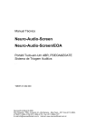
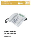
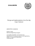
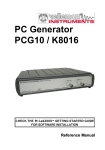
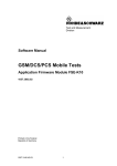
SP8011 GSM Test User Manual V2.0 Beijing Starpoint Technology Company Limited Beijing StarPoint Technology Company Limited >> Sep, 2014 Copyright Notice Copyright © 2014 Beijing StarPoint Technology Company Limited. All Rights Reserved. No part of this manual may be reproduced in any form, written or otherwise, without the express written permission of Beijing StarPoint Technology Company Limited. SP8011 GSM Test User Manual i Beijing StarPoint Technology Company Limited >> Sep, 2014 Contents COPYRIGHT NOTICE ......................................................................................................................... I CONTENTS ........................................................................................................................................... II PREFACE ............................................................................................................................................... 1 1. 2. SP8011 GSM TERMINAL TEST ................................................................................................. 2 1.1. SWITCHING TO GSM SYSTEM ................................................................................................... 2 1.2. GSM SYSTEM OPERATING MODES ........................................................................................... 3 1.2.1. Active Cell Operating Mode ............................................................................................ 4 1.2.2. GSM Analyse Operating Mode ........................................................................................ 5 1.2.3. CW Operating Mode........................................................................................................ 7 1.2.4. Cell Off Operating Mode ................................................................................................. 8 1.3. GSM CALLING PARAMETERS SETTING ..................................................................................... 9 1.4. CALL HANDLING .................................................................................................................... 17 1.4.1. Terminal Registering ..................................................................................................... 17 1.4.2. The Establishing of CS Domain Call Connection ......................................................... 19 1.4.3. The Establishing of PS Domain Data Connection......................................................... 20 1.4.4. Disconnecting CS Domain Call Connection ................................................................. 21 1.4.5. Disconnecting PS Domain Data Connection ................................................................ 22 1.4.6. Emergency Calls ............................................................................................................ 23 1.4.7. The Establishing of CS Domain Not Call Connection ................................................... 23 1.4.8. The Establishing of SRB Not Call Connection .............................................................. 25 TESTING OPERATIONS OF SP8011 GSM ITEMS ............................................................... 27 2.1. GENERAL PROCESS OF TESTING.............................................................................................. 27 2.1.1. Starting Item Testing ...................................................................................................... 27 2.1.2. Terminating Item Testing ............................................................................................... 28 2.1.3. Switching between Testing Items ................................................................................... 28 2.2. THE PROGRESS OF TESTING ITEMS ......................................................................................... 28 2.2.1. Phase Frequency Error ................................................................................................. 28 2.2.2. Transmit Power ............................................................................................................. 31 2.2.3. Power vs. Time .............................................................................................................. 33 2.2.4. Output RF Spectrum ...................................................................................................... 37 2.2.5. Spectrum Monitor .......................................................................................................... 42 2.2.6. EDGE Modulation Accuracy ......................................................................................... 44 2.2.7. GSM Bit Error Rate ....................................................................................................... 47 2.2.8. GSM Terminal Measurements Reported ........................................................................ 49 2.2.9. GPRS Block Error Rate ................................................................................................. 51 2.2.10. GPRS&EDGE Terminal Measurements Reported ......................................................... 54 2.2.11. EDGE SRB Bit Error Rate............................................................................................. 56 2.2.12. GSM Frequency Calibration ......................................................................................... 59 SP8011 GSM Test User Manual ii Beijing StarPoint Technology Company Limited >> Sep, 2014 2.2.13. GSM Power Calibration ................................................................................................ 61 2.2.14. EPSK Frequency Calibration ........................................................................................ 63 2.2.15. EPSK Power Calibration .............................................................................................. 65 2.2.16. Continuous Wave ........................................................................................................... 68 2.2.17. IQ Turing ....................................................................................................................... 70 2.2.18. IQ Imbalance ................................................................................................................. 72 2.2.19. GSM Fast Bit Error Radio ............................................................................................. 74 SP8011 GSM Test User Manual iii Beijing StarPoint Technology Company Limited >> Sep, 2014 Preface SP8011 terminal conformance tester can test GSM, GPRS/EDGE terminal RF indicator on the base of supporting TD-SCDMA terminal RF indicator tests, and it’s capable of operating tests for GSM, GPRS/EDGE terminal RF indicator in both signaling mode and non-signaling mode as well as support the switching between TD-SCDMA RMC12.2k CS and GSM CS in connection condition. This article introduces the relevant contents of GSM, GPRS/EDGE terminal tests using SP8011 terminal conformance tester. SP8011 GSM Test User Manual 1 Beijing StarPoint Technology Company Limited >> Sep, 2014 1. SP8011 GSM Terminal Test 1.1. Switching to GSM System 1. After SP8011 terminal conformance tester boots, the default interface of the TD-SCDMA system is shown as below: Figure 1-1 the default interface of SP8011 terminal conformance tester 2. Press the Configuration button in the front panel control area to enter the system configuration screen, and then press F5 button for setting system mode, as shown below: SP8011 GSM Test User Manual 2 Beijing StarPoint Technology Company Limited >> Sep, 2014 Figure 1-2 the interface of switching systems 3. After GSM is selected, SP8011 terminal conformance tester will switch into the GSM system with the initial interface of Active Cell in the GSM system, as shown below: Figure 1-3 the initial Interface of the GSM System 1.2. GSM System Operating Modes The GSM system of SP8011 terminal conformance tester has four modes, namely Active Cell operating mode, GSM Analyze operating mode, CW operating mode and the Cell Off operating SP8011 GSM Test User Manual 3 Beijing StarPoint Technology Company Limited >> Sep, 2014 mode. After SP8011 terminal conformance tester turns into the GSM system initial interface, press F7 button to set Operating Mode, as shown below: Figure 1- 4 the GSM system mode setting Interface 1.2.1.Active Cell Operating Mode In Active Cell operating mode, the connection established between conformance tester and the terminal can be either CS domain connection or PS domain data connection. When the connection is established, we can test the RF indicators of both transmitter and receiver. In this mode, we can carry out the following operations: Terminal registering and PS domain attaching Terminal emergency calling Establishing call connection between conformance tester and terminal in CS domain Releasing call connection between conformance tester and terminal in CS domain Establishing call connection between conformance tester and terminal in PS domain Releasing call connection between conformance tester and terminal in PS domain Testing terminal transmitter and Receiver RF indicators In Active Cell operating mode, the testable items for different services is shown below: GPRS EDGE Function category Test items GSM Mode A Mode B Mode A Mode B Mode SRB Transmitte r indicator Test of Phase Error and Frequency Error √ √ √ √ √ √ SP8011 GSM Test User Manual 4 Beijing StarPoint Technology Company Limited tests Receiver indicator tests >> Sep, 2014 Transmit Power Test √ √ √ √ √ √ Time switch Template Test √ √ √ √ √ √ Output RF Spectrum Test √ √ √ √ √ √ Spectrum Monitoring Test √ √ √ √ √ √ EDGE Modulation Accuracy Test — — — √ √ √ GSM Bit Error Rate Test √ — — — — — GSM Terminal Measurement Report √ — — — — — GPRS Block Testing — — √ — √ — GPRS&EDGE Terminal Measurements Reported — — √ — √ √ EDGE SRB Bit Error Rate Test — — — — — √ Error Rate 1.2.2.GSM Analyze Operating Mode In GSM Analyze Operating mode, conformance tester doesn’t transmit Downlink signal or establish connection with the terminal, there is no signal controlling flow either. In this mode, we can carry out the following operations: GSM Analyze Frequency Calibrate; GSM Analyze Power Calibrate; EPSK Frequency Calibrate; EPSK Power Calibrate; Output RF Spectrum; Power vs. Time. In GSM Analyze operating mode, the relevant settings of Trigger Mode and Receiver Control are still valid, and the setting steps are as follows: 1. Press More button on the left side, then press F1 button to set Trigger Mode parameters, shown as below: SP8011 GSM Test User Manual 5 Beijing StarPoint Technology Company Limited >> Sep, 2014 Figure 1-1 Trigger mode parameter setting interface 2. Set relevant parameters in the pop-up menu. The range and default value of Trigger Mode parameters: Parameter name Parameter range Default Trigger Mode Auto / Manual Auto Trigger Value -63 ~ 0 -63 3. Press F2 (Receiver Control) button to set the Reference input level of receiver, shown as below: Figure 1-6 Receiver control parameters setting interface SP8011 GSM Test User Manual 6 Beijing StarPoint Technology Company Limited >> Sep, 2014 4. Set relevant parameters in the pop-up menu. The range and default value of Receiver Control parameters: Parameter name MS TX Level Mode Parameter range Default Unit Auto / Manual Auto None -60 ~ 40 13 dBm 0 ~ 31 15 dBm Ref Level TX Level (GSM Analyze Only) 1.2.3.CW Operating Mode In CW operating mode, conformance tester works as a CW signal generator and a CW tester. In this mode, we can carry out the following operations: Transmit CW signals with specified frequency and power; Measure frequency and power of CW signals. In CW operating mode, the relevant setting of CW configuration are still valid, and the setting steps are as follows: 1. Press F6 button to set CW configuration parameters, shown as below: Figure 1-7 CW configuration parameters setting interface 2. Set relevant parameters in the pop-up menu. The range and default value of CW parameters: Parameter name Parameter range Default Unit RF Generator Frequency 330 000 000.00 ~ 2 500 000 000.00 894 000 000.00 Hz RF Analyze Frequency 330 000 000.00 ~ 2 500 000 000.00 894 000 000.00 Hz SP8011 GSM Test User Manual 7 Beijing StarPoint Technology Company Limited >> Sep, 2014 CW Line Loss Uplink -20.00 ~ 60.00 0.00 dB CW Line Loss Downlink -20.00 ~ 60.00 0.00 dB 1.2.4.Cell Off Operating Mode Some parameters of SP8011 conformance tester can only be modified in Cell Off operating mode, the relevant channel parameters of Cell Parameters can be examples. In Cell Off operating mode, the setting steps of Cell Parameters relevant parameters are as follows: 1. Press More button on the right side then press F7 button to set Cell Parameters, shown as below: Figure 1-8 Cell parameters setting interface 2. Set relevant cell parameter in the Pop-up menu. The range and default value of Cell Parameters: Parameter name Parameter range Default TMSI Value 4294967294 4294967294 Mobile DTX State Disable / On / Enable Disable Paging Mode Normal / Reorganization Normal Paging Multi-frames 2~9 5 MCC 0 ~ 999 460 MNC 0 ~ 255 0 Cell ID 0 ~ 63 0 LAC 0 ~ 65535 2 BCC 0~7 5 SP8011 GSM Test User Manual 8 Beijing StarPoint Technology Company Limited >> Sep, 2014 NCC 0~7 1 Cell Bar Access On / Off Off Attach State On / Off On EDGE Request 0/1 0 1.3. GSM Calling Parameters Setting After SP8011 conformance tester is switched to GSM system, we can set GSM calling system parameters. Details are as follows: 1. Press F1 button to set Cell Power, which ranges from -120 dBm to -25 dBm, with a default value of -70 dBm; 2. Press F2 button to set Cell Band, which can be one of PGSM / EGSM / DCS / PCS / RGSM / GSM480 / GSM750 / GSM850 / TGSM810, with a default value of PGSM, shown as below: Figure 1-9 GSM system cell band setting interface 3. Press F3 button ARFCN to set cell down-link channel. The range and default value of ARFCN parameters: Parameter name ARFCN range ARFCN Default PGSM 1 ~ 124 20 EGSM 0 ~ 124, 975 ~ 1023 30 DCS 512 ~ 885 698 PCS 512 ~ 810 698 RGSM 0 ~ 124, 955 ~ 1023 30 GSM850 128 ~ 251 160 TGSM810 350 ~ 425 400 SP8011 GSM Test User Manual 9 Beijing StarPoint Technology Company Limited >> Sep, 2014 GSM750 438 ~ 511 460 GSM480 306 ~ 340 320 4. Press F4 button to set Band Indicator parameter for distinguishing DCS band and PCS band, whose range is 0(representing DCS) / 1(representing PCS) with a default value of 0. This parameter has to be set at first time when DCS or PCS band is switched to. 5. Press F5 button to set Line Loss parameters, we can set up-link/down-link line loss at different bands, shown as below: Figure 1-10 line loss of GSM system setting interface The range and default value of Line Loss parameters: Parameter name Parameter range Default Unit PGSM Uplink -20.00 ~ 60.00 0.00 dB PGSM Downlink -20.00 ~ 60.00 0.00 dB EGSM Uplink -20.00 ~ 60.00 0.00 dB EGSM Downlink -20.00 ~ 60.00 0.00 dB DCS Uplink -20.00 ~ 60.00 0.00 dB DCS Downlink -20.00 ~ 60.00 0.00 dB PCS Uplink -20.00 ~ 60.00 0.00 dB PCS Downlink -20.00 ~ 60.00 0.00 dB RGSM Uplink -20.00 ~ 60.00 0.00 dB RGSM Downlink -20.00 ~ 60.00 0.00 dB GSM480 Uplink -20.00 ~ 60.00 0.00 dB GSM480 Downlink -20.00 ~ 60.00 0.00 dB GSM750 Uplink -20.00 ~ 60.00 0.00 dB GSM750 Downlink -20.00 ~ 60.00 0.00 dB SP8011 GSM Test User Manual 10 Beijing StarPoint Technology Company Limited >> Sep, 2014 GSM850 Uplink -20.00 ~ 60.00 0.00 dB GSM850 Downlink -20.00 ~ 60.00 0.00 dB TGSM810 Uplink -20.00 ~ 60.00 0.00 dB TGSM810 Downlink -20.00 ~ 60.00 0.00 dB 6. Press More button on the left side, then press F3 (Meas Burst) button to set current time slot, which can be one of 1 / 2 / 3 / 4 / 5, with a default value of 1, shown as below: Figure 1-11 Meas Burst parameter setting interface 7. Press F7 button to set GSM system operating mode of SP8011 terminal conformance tester, as shown below: SP8011 GSM Test User Manual 11 Beijing StarPoint Technology Company Limited >> Sep, 2014 Figure 1-12 GSM system operating mode setting interface 8. Press F10 button to set GSM system service category, which can be one of GSM / GPRS / EDGE/ NSFT_CS / NSFT_SRB, with a default value of GSM, shown as below: Figure 1-13 GSM system service category setting interface 1) When the service category is GPRS, press F11 button to set testing mode, setting range is Mode A / Mode B(UM) / Mode B(AM), with a default value of Mode A, shown as below: SP8011 GSM Test User Manual 12 Beijing StarPoint Technology Company Limited >> Sep, 2014 Figure 1-14 GPRS testing mode setting interface 2) When the service category is EDGE, press F11 button to set testing mode, setting range is Mode A / Mode B(UM) / Mode B(AM) / Mode SRB, with a default value of Mode A. Shown as below: 3) Figure 1-15 EDGE testing mode setting interface When the service category is NSFT_CS / NSFT_SRB, press the More in the left side to turn to the second page,then press F2 to set up the detect type,setting range is Synchronies / Asynchronies,with a default value of Synchronies(this parameter can be changed only when cell off). Shown as below: SP8011 GSM Test User Manual 13 Beijing StarPoint Technology Company Limited >> Sep, 2014 Figure 1-16 detect type setting interface 9. Press F12 button (TCH parameters) to set up-link TCH parameters, shown as below: Figure 1-17 TCH signal channel parameter setting interface 1) Press the F7 button to set the up TCH channel slot, which ranges from 0 to 7, with a default value of 5; 2) Press the F8 button to set MS TX Level, which ranges from 0 to 31, with a default value of 15; 10. Press More button on the right side, then press F9 button to set the PDTCH parameters, as SP8011 GSM Test User Manual 14 Beijing StarPoint Technology Company Limited >> Sep, 2014 shown below: Figure 1-18 PDTCH Parameters setting interface 1) Press F8 button to set the PDTCH time slot, as shown below: Figure 1-19 PDTCH Time Slot parameter setting interface The range and default values of PDTCH Time Slot parameters: Parameter SP8011 GSM Test User Manual GPRS / EDGE Mode_A Mode_B 15 Beijing StarPoint Technology Company Limited >> Sep, 2014 Range Default Range Default Uplink Time Slot Number 1/2 2 1/2 1 Downlink Time Slot Number 1/2 1 1/2 1 2) Press F9 button to set the parameters of Channel Coding, as shown below: Figure 1-19 Channel Coding parameter setting interface The range and default values of Channel Coding parameters: GPRS service types Parameter GPRS Mode A GPRS Mode B Range Default Range Default Uplink Channel Coding CS1 ~ CS4 CS1 CS1 ~ CS4 CS1 Downlink Channel Coding — — — — EDGE service types Parameter EDGE Mode A EDGE Mode B / Mode SRB Range Default Range Default Uplink Channel Coding MCS1 ~ MCS9 MCS1 MCS1 ~ MCS9 MCS1 Downlink Channel Coding — — — — 3) Press F10 button to set the parameters of MS TX Level, as shown below: SP8011 GSM Test User Manual 16 Beijing StarPoint Technology Company Limited >> Sep, 2014 Figure 1-21 PDTCH channel MS TX Level parameters setting interface The range and default values of MS TX Level parameters: GPRS / EDGE GPRS / EDGE Mode A Mode B / EDGE Mode SRB Parameter Range Default Range Default MS TX Level Burst1 0 ~ 31 15 0 ~ 31 15 MS TX Level Burst2 0 ~ 31 15 — — MS TX Level Burst3 — — — — MS TX Level Burst4 — — — — MS TX Level Burst5 — — — — 1.4. Call Handling 1.4.1.Terminal Registering Terminal registering steps are as follows: 1. After SP8011 terminal conformance tester boots, we switch to GSM system, then the default interface of the GSM system is shown as below: SP8011 GSM Test User Manual 17 Beijing StarPoint Technology Company Limited >> Sep, 2014 Figure 1-22 the initial interface of GSM system 2. Press F10 button to set the desired type of business; 3. Connect the conformance tester with the terminal; 4. Open the terminal then register it; 1) When the service type is GSM, after the terminal registration is completed, we can see the interface below: Figure 1-23 Register completing interface of GSM system SP8011 GSM Test User Manual 18 Beijing StarPoint Technology Company Limited >> Sep, 2014 2) When the service type is GPRS or EDGE, after the terminal registration is completed, automatic attach to PS domain will be done, then “Attached” will be displayed in the status bar at the right side bottom, as shown below: Figure 1-24 attach completing interface of GPRS / EDGE system 1.4.2.The Establishing of CS Domain Call Connection When the business type is GSM, after a successful registration, we can establish a CS domain call connection following these steps: 1. Establish a CS domain call connection between conformance tester and terminal: MT method: after the registration is completed, press F8 button(Originate Call) to call the terminal, by answering the call, we can establish a CS domain call connection; MO method: after the registration is completed, the terminal dial any number to call, then the conformance tester will answer it automatically, and then a CS domain call connection is established. 2. After a CS domain call connection is established, “CS Connected” will be displayed in the status bar at the right side bottom, as shown below: SP8011 GSM Test User Manual 19 Beijing StarPoint Technology Company Limited >> Sep, 2014 Figure 1-25 CS domain call connection completing interface of GPRS / EDGE system 1.4.3.The Establishing of PS Domain Data Connection When the business type is GPRS or EDGE, after a successful registration and attachment, we can establish a PS domain data connection following these steps: 1. Establish a PS domain data connection between conformance tester and terminal: In the GPRS or EDGE, after a successful registration and attachment, press F9 button (Start Data) to establish a PS domain data connection between conformance tester and terminal; 2. After a PS domain data connection is established, “PS Connected” will be displayed in the status bar at the right side bottom, as shown below: SP8011 GSM Test User Manual 20 Beijing StarPoint Technology Company Limited >> Sep, 2014 Figure 1-26 PS domain data connection establishing complete interface 1.4.4.Disconnecting CS Domain Call Connection Testing completed, we can disconnect the CS domain call connection between conformance tester and the terminal following these steps: 1. Press setup button at the calling button area in the front panel to switch to the default interface of GSM system; 2. Press F8 button(End Call) or hang up to disconnect the CS domain call connection; 3. Conformance tester turn back to IDLE state after CS domain disconnected, shown as below: SP8011 GSM Test User Manual 21 Beijing StarPoint Technology Company Limited >> Sep, 2014 Figure 1-27 IDLE state interfaces after CS domain disconnecting 1.4.5.Disconnecting PS Domain Data Connection Testing completed, we can disconnect the PS domain data connection between conformance tester and the terminal following these steps: 1. Press setup button at the calling button area in the front panel to switch to the default interface of GSM system; 2. Press F9 button (End Data) to disconnect the PS domain data connection; 3. Conformance tester turn back to Attached state after PS domain disconnected, shown as below: SP8011 GSM Test User Manual 22 Beijing StarPoint Technology Company Limited >> Sep, 2014 Figure 1-28 Attached state interface after PS domain disconnecting 1.4.6.Emergency Calls Conformance tester supports emergency calls, including the following two conditions: 1. When SIM card is not inserted in the terminal, conformance tester supports emergency calls in UE, such as: 112,110,119,120, etc., depending on the terminal. 2. When SIM card is inserted in the terminal, conformance tester supports emergency calls in SIM Card, such as: 112,110,119, etc., depending on the SIM card. Remark: Currently, the emergency call number supported by Star Point SIM card is 112,110,119. 1.4.7.The Establishing of CS Domain Not Call Connection When the business type is NSFT_CS, the default page is shown as below: SP8011 GSM Test User Manual 23 Beijing StarPoint Technology Company Limited >> Sep, 2014 Figure 1-29 the default page of NSFT_CS To establish a CS domain not call connection, you should choose the detect type according to the terminal first. After that ,open the terminal and the connection of NSFT_CS can be established. After a CS domain not call connection is established, “NSFT_CS Connected” will be displayed in the status bar at the right side bottom, as shown below: Figure 1-30 CS domain not call connection completing interface of NSFT_CS system SP8011 GSM Test User Manual 24 Beijing StarPoint Technology Company Limited >> Sep, 2014 1.4.8.The Establishing of SRB Not Call Connection When the business type is NSFT_CS, the default page is shown as below: Figure 1-31 the default page of NSFT_SRB To establish a SRB not call connection, you should choose the detect type according to the terminal first. After that ,open the terminal and the connection of NSFT_SRB can be established. After a SRB not call connection is established, “NSFT_SRB Connected” will be displayed in the status bar at the right side bottom, as shown below: SP8011 GSM Test User Manual 25 Beijing StarPoint Technology Company Limited >> Sep, 2014 Figure 1-32 SRB not call connection completing interface of NSFT_SRB system SP8011 GSM Test User Manual 26 Beijing StarPoint Technology Company Limited >> Sep, 2014 2. Testing Operations of SP8011 GSM items 2.1. General Process of Testing Testing operations includes starting item testing, terminating item testing, switching between testing items. The testing process of GSM, GPRS and EDGE are the same, so we take GSM system as an example to introduce the process of testing. 2.1.1. Starting Item Testing In Active Cell operating mode, after CS domain call connection between conformance tester and terminal is established, press Selection button in the measurement button area of front panel, GSM testing items will pop up in a window as shown below: Figure 2-1 GSM testing items selection interface 1. Select the desired testing item in the window, then press the Enter button or knob to start test of the selected item; 2. The testing item launched, the testing result will be displayed as data or Graphics in the screen; 3. While testing, press Single button or Continuous button in the measurement button area the front panel to carry out single or continuous testing. SP8011 GSM Test User Manual 27 Beijing StarPoint Technology Company Limited >> Sep, 2014 2.1.2.Terminating Item Testing After testing, the following two methods can be used to terminate the current testing item: 1. Press Selection button in the measurement button area the front panel, select the current test item in the pop-up menu, then press F10 button (Stop) to terminate the current testing item; 2. Press Stop button in the measurement button area the front panel directly to terminate the current testing item. 2.1.3.Switching between Testing Items During item testing, we can switch testing items if needed. Conformance tester will first terminate the current testing item then start the desired testing item to complete the switching. The switching progress is as follows: 1. Press Selection button then select the new testing item in the pop-up window, as shown below: Figure 2-2 GSM switching interface test items 2. Press Enter button or knob to switch to the new testing item. 2.2. The Progress of Testing Items 2.2.1.Phase Frequency Error Start Item Testing SP8011 GSM Test User Manual 28 Beijing StarPoint Technology Company Limited >> Sep, 2014 In Active Cell operating mode, press the Selection button in the measurement button area of the front panel, then select Phase Frequency Error in the pop-up window to start testing this item. Setup Testing Parameters 1. Press F7 button (Basic Setup) to set the basic parameters, as shown below: Figure 2-3 Basic parameters setting interface Explanations of Basic Setup parameters are as follows: Parameter Parameter Description Parameter Range Default Unit Avg Num The average number of tests, used to set the average number of test results 1 ~ 999 1 None Time Out Timeout, used to set the maximum time of test on condition that no uplink signal is received. 1 ~ 999 20 s Trigger Arm Test trigger, including single test (Single) and continuous test (Continuous). Single / Continuous Continuous None Setting done, we can press the Cancel button to close the setting window; 2. Press F8 button to set the indicators of testing parameters, as shown below: SP8011 GSM Test User Manual 29 Beijing StarPoint Technology Company Limited >> Sep, 2014 Figure 2-4 indicators of testing parameters setting interface Explanations of testing indicators related parameters are as follows: Parameter Name Parameter Description Parameter Range Default Unit Peak Phase Error Peak phase error testing indicators 0.00 ~ 20.00 20.00 deg RMS Phase Error Average phase error testing indicators 0.00 ~ 5.00 5.00 deg Frequency Error Frequency indicators 0.01 ~ 0.10 0.10 ppm error testing Setting done, we can press the Cancel button to close the setting window; 3. Press F9 button to set the parameters of View, you can set the display of testing results, whose range is Numeric / Graph, with a default value of Numeric; 4. Press F10 button to set the state of Marker, whose range is on / off, with a default value of off; 5. Press F11 button to set the abscissa value of Marker X when Marker is on, whose range is 0 ~ 147, with a default value of 0. Display Testing Results Testing results will be displayed on the interface in data and by graph. 1. Testing results displayed in data are as shown below: SP8011 GSM Test User Manual 30 Beijing StarPoint Technology Company Limited >> Sep, 2014 Figure 2-5 the phase frequency error testing results in data 2. Testing results displayed by graph are as shown below: Figure 2-6 the phase frequency error testing results by graph 2.2.2.Transmit Power Start Item Testing In Active Cell operating mode, press the Selection button in the measurement button area of the front panel, then select Transmit Power in the pop-up window to start testing this item. SP8011 GSM Test User Manual 31 Beijing StarPoint Technology Company Limited >> Sep, 2014 Setup Testing Parameters 1. Press F7 button(Basic Setup) to set the basic parameters, as shown below: Figure 2-7 Basic parameters setting interface Explanations of Basic Setup parameters are as follows: Parameter Name Parameter Description Parameter Range Default Unit Avg Num The average number of tests, used to set the average number of test results 1 ~ 999 1 None Time Out Timeout, used to set the maximum time of test on condition that no uplink signal is received. 1 ~ 999 20 s Trigger Arm Test trigger, including single test (Single) and continuous test (Continuous). Single / Continuous Continuous None Setting done, we can press the Cancel button to close the setting window; 2. Press the Single button or Continuous button in the measurement button areas of the front panel to carry out single or continuous testing; 3. Press the Stop button in the measurement button areas of the front panel to terminate the test. Display Testing Results Testing results displayed in data are as shown below: SP8011 GSM Test User Manual 32 Beijing StarPoint Technology Company Limited >> Sep, 2014 Figure 2-8 Transmit power testing results 2.2.3.Power vs. Time Start Item Testing In Active Cell or GSM Analyse operating mode, press the Selection button in the measurement button area of the front panel, then select Power vs. Time in the pop-up window to start testing this item. Setup Testing Parameters 1. Press F7 button(Basic Setup) to set the basic parameters, as shown below: SP8011 GSM Test User Manual 33 Beijing StarPoint Technology Company Limited >> Sep, 2014 Figure 2-9 Basic parameters setting interface Explanations of Basic Setup parameters are as follows: Parameter Name Parameter Description Parameter Range Default Unit Avg Num The average number of tests, used to set the average number of test results 1 ~ 999 1 None Time Out Timeout, used to set the maximum time of test on condition that no uplink signal is received. 1 ~ 999 20 s Trigger Arm Test trigger, including single test (Single) and continuous test (Continuous). Single / Continuous Continuous None Setting done, we can press the Cancel button to close the setting window; 2. Press F8 button to set the Requirement Source, whose range is ETSI / NO Mask, with a default value of ETSI; 3. Press F9 button to set the state of Marker, whose range is on / off, with a default value of off; 4. Press F10 button to set the abscissa value of Marker X when Marker is on, whose range is -30 ~ 572, with a default value of -30; 5. Press F11 button to set the parameters of View, you can set the way of displaying as shown below: SP8011 GSM Test User Manual 34 Beijing StarPoint Technology Company Limited >> Sep, 2014 Figure 2-10 View setting parameters setting interface Explanations of View setting parameters are as follows: Parameter Name Parameter Range Default View Graph / Numeric / Burst1 / Burst2 Graph Graph details Full / Burst1 details / Burst2 details / Guard Full Burst details Complete / Rising / Falling / Useful Complete Setting done, we can press the Cancel button to close the settin0 6. Press F12 button to set the Axis Control parameters, as shown below: Figure 2-11 Axis Control parameters setting interface SP8011 GSM Test User Manual 35 Beijing StarPoint Technology Company Limited >> Sep, 2014 Explanations of Axis Control parameters are as follows: Parameter Name Parameter Description Parameter Range Default Unit Off power Set the minimum vertical coordinate. -120 ~ -10 -80 dBc Reference Set the maximum ordinate. 0 ~ 40 10 dBc Setting done, we can press the Cancel button to close the setting window; 7. Press the Single button or Continuous button in the measurement button areas of the front panel to carry out single or continuous testing. 8. Press the Stop button in the measurement button areas of the front panel to terminate the test. Display Testing Results Testing results will be displayed on the interface in data and by graph. 1. Testing results displayed by graph are as shown below: Figure 2 12 Power vs. Time testing results by graph 2. Testing results displayed in data are as shown below: SP8011 GSM Test User Manual 36 Beijing StarPoint Technology Company Limited >> Sep, 2014 Figure 2-13 Power vs. Time testing results in data 2.2.4.Output RF Spectrum Start Item Testing In Active Cell or GSM Analyse operating mode, press the Selection button in the measurement button area of the front panel, then select Output RF Spectrum in the pop-up window to start testing this item. Setup Testing Parameters 1. Press F7 button(Basic Setup) to set the basic parameters, as shown below: SP8011 GSM Test User Manual 37 Beijing StarPoint Technology Company Limited >> Sep, 2014 Figure 2 14 Basic parameters setting interface Explanations of Basic Setup parameters are as follows: Parameter Name Parameter Description Parameter Range Default Unit Modulation Avg Num Modulation spectrum, the average number of tests, used to set the average number of test results. 1 ~ 999 10 None Switching Avg Num The average number of switching frequency test, used to set the average number of test results. 1 ~ 999 10 None Time Out Timeout, used to set the maximum time of test on condition that no uplink signal is received. 1 ~ 999 20 s Trigger Arm Test trigger, including single test (Single) and continuous test (Continuous). Single / Continuous Single None Setting done, we can press the Cancel button to close the setting window; 2. Press F8 button to set the state of Marker, whose range is On / Off, with a default value of Off; 3. Press F9 button to set the abscissa value of Marker X when Marker is on in a modulation test, whose range is -1800 / -1600 / -1400 / -1.2 thousand / -1000 / -800 / -600 / -400 / -250 / -200 / -100 / 100 / 0 / 200 / 250 / 400 / 600 / 800 / 1000 / 1200 / 1400 / 1600 / 1800, with a default value of -1800; SP8011 GSM Test User Manual 38 Beijing StarPoint Technology Company Limited >> Sep, 2014 4. Press F10 button to set the abscissa value of Marker X when Marker is on in a switching test, whose range is-1800 / -1 200 / -600 / -400 / 400 / 600 / 1200 / 1800 / 0, with a default value of -1800; 5. Press F11 button to set the points used to show the testing results in a modulation spectrum test as shown below. Setting done, we can press the Cancel button to close the setting window: Figure 2-15 modulation spectrum test results showing setting interface 6. Press F12 button to set the points used to show the testing results in a switching spectrum test as shown below. Setting done, we can press the Cancel button to close the setting window: SP8011 GSM Test User Manual 39 Beijing StarPoint Technology Company Limited >> Sep, 2014 Figure 2-16 Switch spectrum test result showing setting interface 7. Press More button on the right side then press F7 button to set the View parameter, whose range is Graph / M Numeric / S Numeric, with a default value of Graph, as shown below: Figure 2-17 Change View parameter setting interface 8. Press the Single button or Continuous button in the measurement button areas of the front panel to carry out single or continuous testing; 9. Press the Stop button in the measurement button areas of the front panel to terminate the test. Display Testing Results SP8011 GSM Test User Manual 40 Beijing StarPoint Technology Company Limited >> Sep, 2014 Testing results will be displayed on the interface in data and by graph. 1. Testing results displayed by graph are as shown below: Figure 2-18 Output RF spectrum testing results by graph 2. Testing results displayed in data are as shown below: Figure 2-19 Output RF Spectrum Modulation spectrum testing result in data SP8011 GSM Test User Manual 41 Beijing StarPoint Technology Company Limited >> Sep, 2014 Figure 2-20 Output RF Spectrum Switch spectrum testing results in data 2.2.5.Spectrum Monitor Start Item Testing In Active Cell operating mode, press the Selection button in the measurement button area of the front panel, then select GSM Spectrum Monitor in the pop-up window to start testing this item. Setup Testing Parameters 1. Press F7 button(Basic Setup) to set the basic parameters, as shown below: SP8011 GSM Test User Manual 42 Beijing StarPoint Technology Company Limited >> Sep, 2014 Figure 2-21 Basic parameters setting interface Explanations of Basic Setup parameters are as follows: Parameter Name Parameter Description Parameter Range Default Unit Avg Num The average number of tests, used to set the average number of test results. 1 ~ 999 1 None Time Out Timeout, used to set the maximum time of test on condition that no uplink signal is received. 1 ~ 20 20 s Trigger Arm Test trigger, including single test (Single) and continuous test (Continuous). Single / Continuous Continuous None Setting done, we can press the Cancel button to close the setting window; 2. Press F8 button to set Y-axis; 3. Press the Single button or Continuous button in the measurement button areas of the front panel to carry out single or continuous testing; 4. Press the Stop button in the measurement button areas of the front panel to terminate the test. Display Testing Results Testing results are displayed by graph, as shown below: SP8011 GSM Test User Manual 43 Beijing StarPoint Technology Company Limited >> Sep, 2014 Figure 2-22 Spectrum Monitoring testing results 2.2.6.EDGE Modulation Accuracy Start Item Testing In Active Cell operating mode, select the EDGE business type, then we can start testing this item following these steps: 1. Press More button in the right side then press F9 button to set the PDTCH Parameters, as shown below: Figure 2-23 PDTCH Parameters setting interface SP8011 GSM Test User Manual 44 Beijing StarPoint Technology Company Limited >> Sep, 2014 2. Press F9 button(Channel Coding) to set the Uplink Channel Coding parameters in the pop-up menu, with a range of MCS5 ~ MCS9, as shown below: Figure 2-24 Channel Coding parameters setting interface 3. Press the Selection button in the measurement button area of the front panel, then select Modulation Accuracy in the pop-up window to start testing this item. Setup Testing Parameters 1. Press F7 button(Basic Setup) to set the basic parameters, as shown below: Figure 2-25 Basic Parameters setting interface SP8011 GSM Test User Manual 45 Beijing StarPoint Technology Company Limited >> Sep, 2014 Explanations of Basic Setup parameters are as follows: Parameter Name Parameter Description Parameter Range Default Unit Avg Num The average number of tests, used to set the average number of test results. 1 ~ 999 1 None Time Out Timeout, used to set the maximum time of test on condition that no uplink signal is received. 1 ~ 999 20 s Trigger Arm Test trigger, including single test (Single) and continuous test (Continuous). Single / Continuous Continuous None IQ Imbalance Calculate State IQ Imbalance Calculate State. Set it as ON if want to do the IQ Imbalance calculate。 ON / OFF OFF None Setting done, we can press the Cancel button to close the setting window; 2. Press the Single button or Continuous button in the measurement button areas of the front panel to carry out single or continuous testing; 3. Press the Stop button in the measurement button areas of the front panel to terminate the test. Display Testing Results Testing results are displayed in data, as shown below: Figure 2-26 EDGE Modulation Accuracy testing results SP8011 GSM Test User Manual 46 Beijing StarPoint Technology Company Limited >> Sep, 2014 2.2.7.GSM Bit Error Rate Start Item Testing In Active Cell operating mode, select the GSM service types then press the Selection button in the measurement button area of the front panel, and then select GSM Bit Error Ratio in the pop-up window to start testing this item. Setup Testing Parameters 1. Press F7 button(Basic Setup) to set the basic parameters, as shown below: Figure 2-27 Basic Parameters setting interface Explanations of Basic Setup parameters are as follows: Parameter Name Parameter Description Parameter Range Default Unit Time Out Timeout, used to set the maximum time of test on condition that no uplink signal is received. 1 ~ 999 20 s Trigger Arm Test trigger, including single test (Single) and continuous test (Continuous). Single / Continuous Single None Setting done, we can press the Cancel button to close the setting window; 2. Press F8 button to set the BER Parameters, as shown below: SP8011 GSM Test User Manual 47 Beijing StarPoint Technology Company Limited >> Sep, 2014 Figure 2 28 BER Parameters setting interface Explanations of BER Parameters are as follows: Parameter Name Parameter Range Default Unit Measurement Type TYPEIA / TYPEII / TYPEIB / Residual TYPEIA / Residual TYPEII / Residual TYPEIB Residual TYPEIA None Close Loop Signaling Delay 0.00 ~ 5 000.00 500.00 ms Number of Bits 1000 ~ 999000 10000 Bit BER Requirement 0~1 0.001 None Source Type PN15/ABits PN15 None Setting done, we can press the Cancel button to close the setting window; 3. Press the Single button or Continuous button in the measurement button areas of the front panel to carry out single or continuous testing; 4. Press the Stop button in the measurement button areas of the front panel to terminate the test. Display Testing Results Testing results are displayed in data, as shown below: SP8011 GSM Test User Manual 48 Beijing StarPoint Technology Company Limited >> Sep, 2014 Figure 2 29 Bit Error Rate testing results 2.2.8.GSM Terminal Measurements Reported Start Item Testing In Active Cell operating mode, select the GSM service types and press the Selection button in the measurement button area of the front panel, then select GSM MS Report in the pop-up window to start testing this item. Setup Testing Parameters 1. Press F7 button(Basic Setup) to set the basic parameters, as shown below: SP8011 GSM Test User Manual 49 Beijing StarPoint Technology Company Limited >> Sep, 2014 Figure 2-30 Basic Parameters setting interface Explanations of Basic Setup parameters are as follows: Parameter Name Parameter Description Parameter Range Default Unit Time Out Timeout, used to set the maximum time of test on condition that no uplink signal is received. 1 ~ 999 20 s Trigger Arm Test trigger, including single test (Single) and continuous test (Continuous). Single / Continuous Single None Setting done, we can press the Cancel button to close the setting window; 2. Press the Single button or Continuous button in the measurement button areas of the front panel to carry out single or continuous testing; 3. Press the Stop button in the measurement button areas of the front panel to terminate the test. Display Testing Results Testing results are displayed in data, as shown below: SP8011 GSM Test User Manual 50 Beijing StarPoint Technology Company Limited >> Sep, 2014 Figure 2-31 GSM Terminal Measurements Reported testing results 2.2.9.GPRS Block Error Rate Start Item Testing In Active Cell operating mode, select the EDGE Mode_B or GPRS Mode_B service types and press the Selection button in the measurement button area of the front panel, then select GPRS Block Error Ratio in the pop-up window to start testing this item. Setup Testing Parameters 1. Press F7 button(Basic Setup) to set the basic parameters, as shown below: SP8011 GSM Test User Manual 51 Beijing StarPoint Technology Company Limited >> Sep, 2014 Figure 2 32 Basic parameters setting interface Explanations of Basic Setup parameters are as follows: Parameter Name Parameter Description Parameter Range Default Unit Time Out Timeout, used to set the maximum time of test on condition that no uplink signal is received. 1 ~ 20 20 s Trigger Arm Test trigger, including single test (Single) and continuous test (Continuous). Single / Continuous Single None Setting done, we can press the Cancel button to close the setting window; 2. Press F8 button to set BLER Parameters, as shown below: SP8011 GSM Test User Manual 52 Beijing StarPoint Technology Company Limited >> Sep, 2014 Figure 2-33 BLER Parameters setting interface Explanations of BLER Parameters are as follows: Parameter Name Parameter Range Default Unit Requirement 0.01 ~ 1.00 0.01 None Number of Blocks 1 ~ 99000 500 Bit Source Type PN15/ABits PN15 None Setting done, we can press the Cancel button to close the setting window; 3. Press the Single button or Continuous button in the measurement button areas of the front panel to carry out single or continuous testing; 4. Press the Stop button in the measurement button areas of the front panel to terminate the test. Display Testing Results Testing results are displayed in data, as shown below: SP8011 GSM Test User Manual 53 Beijing StarPoint Technology Company Limited >> Sep, 2014 Figure 2-34 GPRS Block Error Rate testing results 2.2.10. GPRS&EDGE Terminal Measurements Reported Start Item Testing In Active Cell operating mode, select the GPRS Mode B, EDGE Mode B or EDGE Mode SRB service types and press the Selection button in the measurement button area of the front panel, then select GPRS & EDGE MS Report in the pop-up window to start testing this item. Setup Testing Parameters 1. Press F7 button(Basic Setup) to set the basic parameters, as shown below: SP8011 GSM Test User Manual 54 Beijing StarPoint Technology Company Limited >> Sep, 2014 Figure 2-35 Basic Parameters setting interface Explanations of Basic Setup parameters are as follows: Parameter Name Parameter Description Parameter Range Default Unit Time Out Timeout, used to set the maximum time of test on condition that no uplink signal is received. 1 ~ 999 20 s Trigger Arm Test trigger, including single test (Single) and continuous test (Continuous). Single / Continuous Single None Setting done, we can press the Cancel button to close the setting window; 2. Press the Single button or Continuous button in the measurement button areas of the front panel to carry out single or continuous testing; 3. Press the Stop button in the measurement button areas of the front panel to terminate the test. Display Testing Results Testing results are displayed in data, as shown below: SP8011 GSM Test User Manual 55 Beijing StarPoint Technology Company Limited >> Sep, 2014 Figure 2-36 GPRS & EDGE terminal measurement reported testing results after GPRS Figure 2-37 GPRS & EDGE terminal measurement reported testing results after EDGE 2.2.11. EDGE SRB Bit Error Rate Start Item Testing In Active Cell operating mode, select the EDGE Mode SRB business type and press the Selection button in the measurement button area of the front panel, then select EDGE Bit Error Ratio in the pop-up window to start testing this item. SP8011 GSM Test User Manual 56 Beijing StarPoint Technology Company Limited >> Sep, 2014 Setup Testing Parameters 1. Press F7 button(Basic Setup) to set the basic parameters, as shown below: Figure 2-38 Basic parameters setting interface Explanations of Basic Setup parameters are as follows: Parameter Name Parameter Description Parameter Range Default Unit Time Out Timeout, used to set the maximum time of test on condition that no uplink signal is received. 1 ~ 999 20 s Trigger Arm Test trigger, including single test (Single) and continuous test (Continuous). Single / Continuous Single None Setting done, we can press the Cancel button to close the setting window: 2. Press F8 button to set the BER Parameters, as shown below: SP8011 GSM Test User Manual 57 Beijing StarPoint Technology Company Limited >> Sep, 2014 Figure 2-39 BER Parameters setting interface Explanations of BER Parameters are as follows: Parameter Name Parameter Range Default Unit BER Requirement 0.000 ~ 1.000 0.001 None Number of Bits 1000 ~ 999000 10000 Bit Source Type PN15/ABits PN15 None Setting done, we can press the Cancel button to close the setting window; 3. Press the Single button or Continuous button in the measurement button areas of the front panel to carry out single or continuous testing; 4. Press the Stop button in the measurement button areas of the front panel to terminate the test. Display Testing Results Testing results are displayed in data, as shown below: SP8011 GSM Test User Manual 58 Beijing StarPoint Technology Company Limited >> Sep, 2014 Figure 2-40 EDGE SRB Bit Error Rate testing results 2.2.12. GSM Frequency Calibration Start Item Testing In GSM Analyse operating mode, press the Selection button in the measurement button area of the front panel, then select Frequency Calibrate in the pop-up window to start testing this item. Setup Testing Parameters 1. Press F7 button(Basic Setup) to set the basic parameters, as shown below: SP8011 GSM Test User Manual 59 Beijing StarPoint Technology Company Limited >> Sep, 2014 Figure 2-41 Basic Parameters setting interface Explanations of Basic Setup parameters are as follows: Parameter Name Parameter Description Parameter Range Default Unit Avg Num The average number of tests, used to set the average number of test results. 1 ~ 999 1 None REPEAT / EXP REPEAT Nonr Single / Continuous Continuous None Average Mode Trigger Arm Set up the average mode of test. Test trigger, including single test (Single) and continuous test (Continuous). Setting done, we can press the Cancel button to close the setting window; 2. Press the Single button or Continuous button in the measurement button areas of the front panel to carry out single or continuous testing; 3. Press the Stop button in the measurement button areas of the front panel to terminate the test. Display Testing Results Testing results are displayed in data, as shown below: SP8011 GSM Test User Manual 60 Beijing StarPoint Technology Company Limited >> Sep, 2014 Figure 2-42 GSM Frequency Calibration testing results 2.2.13. GSM Power Calibration Start Item Testing In GSM Analyse operating mode, press the Selection button in the measurement button area of the front panel, then select Power Calibrate in the pop-up window to start testing this item. Setup Testing Parameters 1. Press F7 button(Basic Setup) to set the basic parameters, as shown below: SP8011 GSM Test User Manual 61 Beijing StarPoint Technology Company Limited >> Sep, 2014 Figure 2-43 Basic Parameters setting interface Explanations of Basic Setup parameters are as follows: Parameter Name Parameter Description Parameter Range Default Unit Time Out Timeout, used to set the maximum time of test on condition that no uplink signal is received. 1 ~ 20 20 s Trigger Arm Test trigger, including single test (Single) and continuous test (Continuous). Single / Continuous Continuous None Setting done, we can press the Cancel button to close the setting window; 2. Press F8 button to set the parameters N, standing for the bursts tested. This parameter has a range of 1 to 300, with a default value of 200; 3. Press F9 button to set the state of Marker, whose range is on / off, with a default value of off; 4. Press F10 button to set the abscissa value of Marker X when Marker is on, whose range is 0 ~ N-1, with a default value of 0; 5. Press the Single button or Continuous button in the measurement button areas of the front panel to carry out single or continuous testing; 6. Press the Stop button in the measurement button areas of the front panel to terminate the test. Display Testing Results Test results are displayed by graph, as shown below: SP8011 GSM Test User Manual 62 Beijing StarPoint Technology Company Limited >> Sep, 2014 Figure 2-44 GSM Power Calibration testing results 2.2.14. EPSK Frequency Calibration Start Item Testing In GSM Analyse operating mode, press the Selection button in the measurement button area of the front panel, then select EPSK Frequency Calibrate in the pop-up window to start testing this item. Setup Testing Parameters 1. Press F7 button(Basic Setup) to set the basic parameters, as shown below: SP8011 GSM Test User Manual 63 Beijing StarPoint Technology Company Limited >> Sep, 2014 Figure 2-45 Basic Parameters setting interface Explanations of Basic Setup parameters are as follows: Parameter Name Parameter Description Parameter Range Default Unit Avg Num The average number of tests, used to set the average number of test results. 1 ~ 999 1 None Trigger Arm Test trigger, including single test (Single) and continuous test (Continuous). Single / Continuous Continuous None Setting done, we can press the Cancel button to close the setting window; 2. Press the Single button or Continuous button in the measurement button areas of the front panel to carry out single or continuous testing; 3. Press the Stop button in the measurement button areas of the front panel to terminate the test. Display Testing Results Testing results are displayed in data, as shown below: SP8011 GSM Test User Manual 64 Beijing StarPoint Technology Company Limited >> Sep, 2014 Figure 2-46 EPSK Frequency Calibration testing results 2.2.15. EPSK Power Calibration Start Item Testing In GSM Analyse operating mode, press the Selection button in the measurement button area of the front panel, then select EPSK Power Calibrate in the pop-up window to start testing this item. Setup Testing Parameters 1. Press F7 button(Basic Setup) to set the basic parameters, as shown below: SP8011 GSM Test User Manual 65 Beijing StarPoint Technology Company Limited >> Sep, 2014 Figure 2-47 Basic Parameters setting interface Explanations of Basic Setup parameters are as follows: Parameter Name Parameter Description Parameter Range Default Unit Time Out Timeout, used to set the maximum time of test on condition that no uplink signal is received. 1 ~ 20 20 s Trigger Arm Test trigger, including single test (Single) and continuous test (Continuous). Single / Continuous Continuous None Setting done, we can press the Cancel button to close the setting window; 2. Press F8 button to set the parameters N, standing for the bursts tested. This parameter has a range of 1 to 300, with a default value of 200; 3. Press F9 button to set the Range of parameters Y, as shown below: SP8011 GSM Test User Manual 66 Beijing StarPoint Technology Company Limited >> Sep, 2014 Figure 2-48 Range of Y setting interface Explanations of range of Y are as follows: Parameter Name Parameter Description Parameter Range Default Unit Y Range Bottom Set the minimum vertical coordinate. -80 ~ -10 -10 None Y Range Top Set the maximum ordinate. -10 ~ 60 30 None Y Range Step Setting Y axis scale interval. 1 ~ 20 5 None Setting done, we can press the Cancel button to close the setting window; 4. Press F10 button to set the state of Marker, whose range is On / Off, with a default value of Off; 5. Press F11 button to set the abscissa value of Marker X when Marker is on, whose range is 0 ~ N-1, with a default value of 0; 6. Press the Single button or Continuous button in the measurement button areas of the front panel to carry out single or continuous testing; 7. Press the Stop button in the measurement button areas of the front panel to terminate the test. Display Testing Results Test results are displayed by graph, as shown below: SP8011 GSM Test User Manual 67 Beijing StarPoint Technology Company Limited >> Sep, 2014 Figure 2-49 EPSK Power Calibration testing results 2.2.16. Continuous Wave Start Item Testing In CW operating mode, press the Selection button in the measurement button area of the front panel, then select Continuous Wave in the pop-up window to start testing this item. Setup Testing Parameters 1. Press F7 button(Basic Setup) to set the basic parameters, as shown below: SP8011 GSM Test User Manual 68 Beijing StarPoint Technology Company Limited >> Sep, 2014 Figure 2-50 Basic Parameters setting interface Explanations of Basic Setup parameters are as follows: Parameter Name Parameter Description Parameter Range Default Unit Time Out Timeout, used to set the maximum time of test on condition that no uplink signal is received. 1 ~ 999 20 s Trigger Arm Test trigger, including single test (Single) and continuous test (Continuous). Single / Continuous Continuous None Setting done, we can press the Cancel button to close the setting window; 2. Press the Single button or Continuous button in the measurement button areas of the front panel to carry out single or continuous testing. 3. Press the Stop button in the measurement button areas of the front panel to terminate the test. Display Testing Results Testing results are displayed in data, as shown below: SP8011 GSM Test User Manual 69 Beijing StarPoint Technology Company Limited >> Sep, 2014 Figure 2-51 Continuous Wave testing results 2.2.17. IQ Turing Start Item Testing In GSM Analyse operating mode, press the Selection button in the measurement button area of the front panel, then select GSM IQ Tuning in the pop-up window to start testing this item. Setup Testing Parameters 1. Press F7 button(Basic Setup) to set the basic parameters, as shown below: SP8011 GSM Test User Manual 70 Beijing StarPoint Technology Company Limited >> Sep, 2014 Figure 2-52 Basic Parameters setting interface Explanations of Basic Setup parameters are as follows: Parameter Name Parameter Description Parameter Range Default Unit Avg Num The average number of tests, used to set the average number of test results. 1 ~ 999 1 None Time Out Timeout, used to set the maximum time of test on condition that no uplink signal is received. 1 ~ 999 20 s Trigger Arm Test trigger, including single test (Single) and continuous test (Continuous). Single / Continuous Continuous None -67.7 / 0 / 67.7 0 kHz Ref Frequency The Ref Frequency. Setting done, we can press the Cancel button to close the setting window; 2. Press F8 to set up change view, can change the display mode of the results. Whose range is Numeric / Graph, with default value of Graph. 3. Press the Single button or Continuous button in the measurement button areas of the front panel to carry out single or continuous testing. 4. Press the Stop button in the measurement button areas of the front panel to terminate the test. Display Testing Results Testing results are displayed in graph, as shown below: SP8011 GSM Test User Manual 71 Beijing StarPoint Technology Company Limited >> Sep, 2014 Figure 2-53 IQ Turning testing results by graph Testing results are displayed in data, as shown below: Figure 2-54 IQ Turning testing results in data 2.2.18. IQ Imbalance Start Item Testing In GSM Analyse operating mode, press the Selection button in the measurement button area of the SP8011 GSM Test User Manual 72 Beijing StarPoint Technology Company Limited >> Sep, 2014 front panel, then select Modulation Accuracy in the pop-up window to start testing this item. Setup Testing Parameters 1. Press F7 button(Basic Setup) to set the basic parameters, as shown below: Figure 2-55 Basic Parameters setting interface Explanations of Basic Setup parameters are as follows: Parameter Name Parameter Description Parameter Range Default Unit Avg Num The average number of tests, used to set the average number of test results. 1 ~ 999 1 None Time Out Timeout, used to set the maximum time of test on condition that no uplink signal is received. 1 ~ 999 20 s Trigger Arm Test trigger, including single test (Single) and continuous test (Continuous). Single / Continuous Continuous None The state Calculation. OFF / ON OFF None IQ Imbalance Calculate State of IQ Imbalance 2. Set up the IQ Imbalance Calculate State as ON ,then can start the calculation. 3. Press the Single button or Continuous button in the measurement button areas of the front panel to carry out single or continuous testing. 4. Press the Stop button in the measurement button areas of the front panel to terminate the test. SP8011 GSM Test User Manual 73 Beijing StarPoint Technology Company Limited >> Sep, 2014 Display Testing Results Testing results are displayed in data, as shown below: Figure 2-56 IQ Imbalance testing results 2.2.19. GSM Fast Bit Error Radio Start Item Testing In Active Cell operating mode, select the GSM service types then press the Selection button in the measurement button area of the front panel, and then select GSM Fast Bit Error Ratio in the pop-up window to start testing this item. Setup Testing Parameters 1. Press F7 button(Basic Setup) to set the basic parameters, as shown below: SP8011 GSM Test User Manual 74 Beijing StarPoint Technology Company Limited >> Sep, 2014 Figure 2-57 Basic Parameters setting interface Explanations of Basic Setup parameters are as follows: Parameter Name Parameter Description Parameter Range Default Unit Time Out Timeout, used to set the maximum time of test on condition that no uplink signal is received. 1 ~ 999 20 s Trigger Arm Test trigger, including single test (Single) and continuous test (Continuous). Single / Continuous Single None Setting done, we can press the Cancel button to close the setting window; 2. Press F8 button to set the BER parameters, as shown below: SP8011 GSM Test User Manual 75 Beijing StarPoint Technology Company Limited >> Sep, 2014 Figure 2-58 BER Parameters setting interface Explanations of BER Setup parameters are as follows: Parameter Name Parameter Range Default Unit Number of Bits 1000 ~ 999000 10000 Bit Requirement(e-4) 0 ~ 10000 10 无 Setting done, we can press the Cancel button to close the setting window; 3. Press the Single button or Continuous button in the measurement button areas of the front panel to carry out single or continuous testing. 4. Press the Stop button in the measurement button areas of the front panel to terminate the test. Display Testing Results Testing results are displayed in data, as shown below: SP8011 GSM Test User Manual 76 Beijing StarPoint Technology Company Limited >> Sep, 2014 Figure 2-59 GSM Fast BER testing results SP8011 GSM Test User Manual 77