1
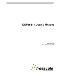
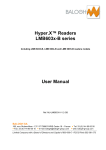
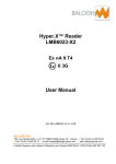
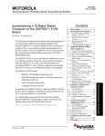
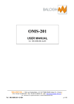
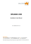
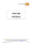
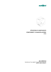
ASVA
Onboard Equipment
TECHNICAL DATA SHEET
Ref: M - LMB23ASVA - V1.3-EN
189, rue d’Aubervilliers - C.P. 97 75886 PARIS Cedex 18 – France
Fax : 33 (0)1 44 65 65 10
e-mail : [email protected]
Tél : 33 (0)1 44 65 65 00
web : balogh-group.com
Public limited company with Board of Directors and a share capital of 800 000 € - Paris RCS No. 582 061 073
ASVA – Onboard equipment
CONTENTS
1
PRESENTATION .........................................................................................4
2
DESCRIPTION.............................................................................................5
2.1
EXTERNAL DESCRIPTION ........................................................................................5
2.2
INTERNAL DESCRIPTION OF THE READER UNIT..................................................9
3
INTERFACE WITH THE MIMIC PANEL....................................................11
4
READER CONFIGURATION .....................................................................14
4.1
ACCESSING THE CONTROL PANEL ...................................................................... 14
4.2
CONTROL PANEL OPERATION .............................................................................. 14
4.3
ADJUSTABLE PARAMETERS.................................................................................. 15
5
INSTALLATION .........................................................................................21
5.1
READER ................................................................................................................... 21
5.2
ANTENNA ................................................................................................................. 21
5.3
JUMPER CABLES .................................................................................................... 21
6
OPERATION ..............................................................................................23
6.1
POWER SUPPLY...................................................................................................... 23
6.2
POWERING UP ........................................................................................................ 23
6.3
DATA COLLECTION TAG SCANNING..................................................................... 24
6.4
FAULT FINDING ....................................................................................................... 25
APPENDICES ...................................................................................................26
1
EC NOTICE................................................................................................26
2
OVERALL DIMENSIONS ..........................................................................27
3
BILL OF MATERIAL OF THE CONNECTION...........................................29
3
BILL OF MATERIAL OF THE CONNECTION...........................................30
4
BASE READER FACTORY CONFIGURATION........................................31
BALOGH SA, 189 rue d’Aubervilliers C.P. 97 75886 PARIS Cedex 18 FRANCE
p2/34
Tél: 33 (0)1 44 65 65 00 Fax: 33 (0)1 44 65 65 10 Internet: http://www.balogh-group.com
Public limited company with Board of Directors and a share capital of 800 000 € - Paris RCS No. 582 061 073
Subject to change - Ref : M - LMB23ASVA - V1.3-EN
ASVA – Onboard equipment
FOREWORD
Object of this technical manual
This technical manual describes the ASVA equipment supplied by Balogh and fitted onboard the
carriages.
The manual provides details on equipment installation and operation.
The performances and general characteristics of each of the system’s components are quoted in
the technical data sheets applicable to the relevant component.
Technical manual reference
The technical manual has been given the following generic reference:
M - <equipment designation> - Vx.y - L where
M stands for Manual
x is the equipment version number
y is the document change index
L is the language used.
Updates
Indice
Date
Nature de la modification
1
12/09/03 creation
2
26/09/03 - tree structure modification
- modification of default values for some config. parameters.
- modification of markings on HE 302 base
- antenna overall dimensions and configuration example added in
appendix
- minor amendments
3
07/01/04 - Presentation chapter added
- block diagram replaced by photo, improved iconography
- interconnection diagram and section on supervisor interface added
- a connector technology nomenclature and configuration added as an
appendix
- document coding altered
Note
The information contained in this manual is subject to change without any advance notification.
The BALOGH Company cannot be held liable for consequences ensuing on any errors or
omissions, nor for the misinterpretation of information.
BALOGH SA, 189 rue d’Aubervilliers C.P. 97 75886 PARIS Cedex 18 FRANCE
p3/34
Tél: 33 (0)1 44 65 65 00 Fax: 33 (0)1 44 65 65 10 Internet: http://www.balogh-group.com
Public limited company with Board of Directors and a share capital of 800 000 € - Paris RCS No. 582 061 073
Subject to change - Ref : M - LMB23ASVA - V1.3-EN
ASVA – Onboard equipment
1 PRESENTATION
Balogh equipment comprises:
• onboard equipment: reader, antenna and interconnection jumper cables,
• fixed equipment: data collection tags recessed into their shoes fixed to the ground.
T
SUPERVISOR
Superviseur
ASVA Actuators
Actionneurs
ASVA
R
A
I
N
READER
BASE
Base lecteur
Interconnection
cables
câblots
d’interconnexion
Antenna
Antenne
B
A
L
O
G
H
GROUND
SOL
BDG_1090dans
in tag housing
Badge
sabot
BALOGH SA, 189 rue d’Aubervilliers C.P. 97 75886 PARIS Cedex 18 FRANCE
p4/34
Tél: 33 (0)1 44 65 65 00 Fax: 33 (0)1 44 65 65 10 Internet: http://www.balogh-group.com
Public limited company with Board of Directors and a share capital of 800 000 € - Paris RCS No. 582 061 073
Subject to change - Ref : M - LMB23ASVA - V1.3-EN
ASVA – Onboard equipment
2 DESCRIPTION
2.1
EXTERNAL DESCRIPTION
The reader is an LMB_7023-E comprising:
• a reader base LMB_7003-E,
• an AT2_2720 antenna equipped with 30 cm coaxial connectors,
• two jumper cables used as extensions to connect the two subassemblies:
BALOGH SA, 189 rue d’Aubervilliers C.P. 97 75886 PARIS Cedex 18 FRANCE
p5/34
Tél: 33 (0)1 44 65 65 00 Fax: 33 (0)1 44 65 65 10 Internet: http://www.balogh-group.com
Public limited company with Board of Directors and a share capital of 800 000 € - Paris RCS No. 582 061 073
Subject to change - Ref : M - LMB23ASVA - V1.3-EN
ASVA – Onboard equipment
The LMB_7003-E reader base is housed in a stainless steel box closed off by a U-shaped cover
fixed by means of four Ø6 Allen screws:
Height: 90 mm
Depth: 270 mm.
Box width: 190 mm.
Cover footprint: 270 x 230 mm.
4 oblong holes 7 x 14 mm drilled through the cover for fixing (centre-centre distances: 210 x 210 mm).
The connection panel comprises:
• two TNC bases marked « ANT IN » and « ANT OUT » (the ANT OUT base has a red collar)
for antenna connection,
• one HE302 bayonet 6-contact base used to connect the power supply and the RS
485 interface:
BALOGH SA, 189 rue d’Aubervilliers C.P. 97 75886 PARIS Cedex 18 FRANCE
p6/34
Tél: 33 (0)1 44 65 65 00 Fax: 33 (0)1 44 65 65 10 Internet: http://www.balogh-group.com
Public limited company with Board of Directors and a share capital of 800 000 € - Paris RCS No. 582 061 073
Subject to change - Ref : M - LMB23ASVA - V1.3-EN
ASVA – Onboard equipment
The AT2_2720 antenna is a one-piece moulded casting measuring 325 x 90 x 22 mm; the
stainless steel base plate is covered with a radome and equipped with two coaxial connectors,
each terminating in a male TNC connector marked «ANT IN» (black) or «ANT OUT» (red):
A two colour indicator light (visible on the left) relays the information from the internal indicator light
to the reader (see following). Each of the fixing holes drilled through the four corners of the
antenna are blanked off with plastic connectors.
BALOGH SA, 189 rue d’Aubervilliers C.P. 97 75886 PARIS Cedex 18 FRANCE
p7/34
Tél: 33 (0)1 44 65 65 00 Fax: 33 (0)1 44 65 65 10 Internet: http://www.balogh-group.com
Public limited company with Board of Directors and a share capital of 800 000 € - Paris RCS No. 582 061 073
Subject to change - Ref : M - LMB23ASVA - V1.3-EN
ASVA – Onboard equipment
Les deux câblots ont un câble et des connecteurs identiques ; seul le marquage ‘‘ANT IN’’ / ‘‘ANT
OUT’’ les différentie :
They comprise:
• on one side, a male angled TNC connector for easy connection to the reader base:
•
on the other, a female TNC connector with an assembly plate for connection into the
antenna:
N.B. jumper cables may be of different colours (e,g, black or white) depending on the series.
BALOGH SA, 189 rue d’Aubervilliers C.P. 97 75886 PARIS Cedex 18 FRANCE
p8/34
Tél: 33 (0)1 44 65 65 00 Fax: 33 (0)1 44 65 65 10 Internet: http://www.balogh-group.com
Public limited company with Board of Directors and a share capital of 800 000 € - Paris RCS No. 582 061 073
Subject to change - Ref : M - LMB23ASVA - V1.3-EN
ASVA – Onboard equipment
2.2
INTERNAL DESCRIPTION OF THE READER UNIT
Internal connections
After passing through the TNC bases, the antenna links terminate on the inter-antenna plate.
After passing through base HE302, the power supply and the serial link are connected to the
reader by means of wires crimped on to contacts soldered onto the printed circuit:
ANT IN
ANT OUT
RS 485 serial link and power supply
Reader base man-machine interface: instrument panel:
led low
voltage
DT06
JK01
1 2 3
Input/output status
DR03 DR04 DR05 DR06
reset
Main light
indicator
DN02
Status link
TTL
DR09
TTL link
JT01
JR04
1 2 3 4
Input
JR03
1 2 3 4 5 6
Output
Serial link activity
DR 07 DR08
RS link
JR02
JR01
1 2 3 4 5
1 2 3 4 5
Display
UN17 - UN18
buzzer
BALOGH SA, 189 rue d’Aubervilliers C.P. 97 75886 PARIS Cedex 18 FRANCE
p9/34
Tél: 33 (0)1 44 65 65 00 Fax: 33 (0)1 44 65 65 10 Internet: http://www.balogh-group.com
Public limited company with Board of Directors and a share capital of 800 000 € - Paris RCS No. 582 061 073
Subject to change - Ref : M - LMB23ASVA - V1.3-EN
ASVA – Onboard equipment
The following constitute the main control elements:
• a two-colour indicator light (DN02) indicating reader status and the presence of a data
collection tag,
• a buzzer (if activated) that sounds when a data collection tag is detected,
• a reset pushbutton (black),
• a control panel comprising two 7-segment display units (UN17-UN18) and two push
buttons:
Select/Save
Display/Change
BALOGH SA, 189 rue d’Aubervilliers C.P. 97 75886 PARIS Cedex 18 FRANCE
p10/34
Tél: 33 (0)1 44 65 65 00 Fax: 33 (0)1 44 65 65 10 Internet: http://www.balogh-group.com
Public limited company with Board of Directors and a share capital of 800 000 € - Paris RCS No. 582 061 073
Subject to change - Ref : M - LMB23ASVA - V1.3-EN
ASVA – Onboard equipment
3 INTERFACE WITH THE MIMIC PANEL
Hors
fourniture
BALOGH BASE
LECTEUR
Not provided
by BALOGH
BALOGH
READERBALOGH
BASE
Physical interface:
The reader base and the mimic panel communicate through an RS 485 link:
JR 01 connector
connecteur
JR 01
JT 01 connector
connecteur
JT 01
Tx+ Tx- Rx+ Rx- Gnd
1
2
3
4
5
+
-
B
A
B
A
Internal
câblage
interne
connection
D
F
C
E
HE 302 socket
embase
HE 302
HE 302
fiche
HEplug
302
D
+V -V
F
C
E
0V
strap
externe
External
strap
for RS485
pour
RS485
12 Vdc
à
24 Vdc
RS 485 série
serial link
liaison
RS 485
0 Volt
alimentation
Power supply
N.B.
1) The serial link and power supply cables, the HE 302 connector and the strap are not supplied by
Balogh.
2) The “+V” line is high when inactive and low when active; the reverse applies to the “-V” line.
3) We recommend using a shielded cable to protect against interference.
4) In order to adapt a line, a friction resistance mechanism may have to be inserted between wires
+V and –V (please refer to the Hyper X reader interfaces Manual, ref. 13053/104).
5) Typical configuration: for instance, when the following values apply to the serial link parameters
(please refer to the following section):
• at physical and frame levels: RS 485 (n°11) at 19 200 bauds (n°14), using 8 bits without parity (n°15),
• at protocol level: interr. mode (n°17), 4 transmissions max. (n°19), in JBUS (n°16), at address 2 (n°13):
BALOGH SA, 189 rue d’Aubervilliers C.P. 97 75886 PARIS Cedex 18 FRANCE
p11/34
Tél: 33 (0)1 44 65 65 00 Fax: 33 (0)1 44 65 65 10 Internet: http://www.balogh-group.com
Public limited company with Board of Directors and a share capital of 800 000 € - Paris RCS No. 582 061 073
Subject to change - Ref : M - LMB23ASVA - V1.3-EN
ASVA – Onboard equipment
n°
11
13
14
15
16
17
19
Parameter
RS interface type
JBUS address
Rate
Character format
Mnemonic
tA
Ad
br
Fo
Frame type
Polling/Interr
Max. number
transmissions.
Typical value
RS 485
2
19 200 bauds
8 bits without
parity
JBUS
interruption
4
Fr
Po
nE
Typical value displayed
48
2
19
8n
Jb
oF
4
Hors
fourniture
BALOGH BASE
Not provided
by BALOGH
BALOGH
LECTEUR
READER
BALOGH
BASE
6) Option of connecting an RS 232 link:
connecteur
JR 01
JR 01 connector
connecteur
JT 01
JT 01 connector
Tx+ Tx- Rx+ Rx- Gnd
1
2
3
4
5
+
-
B
A
Internal
câblage
interne
connection
D
F
C
E
HE 302 socket
embase
HE 302
fiche
HEplug
302
HE 302
D
C
Tx
E
Rx 0Volt
RS 232 serial
liaison
sérielink
RS 232
B
12 Vdc
à
24 Vdc
A
0Volt
alimentation
Power supply
Parameter n°11 must be on RS 232.
BALOGH SA, 189 rue d’Aubervilliers C.P. 97 75886 PARIS Cedex 18 FRANCE
p12/34
Tél: 33 (0)1 44 65 65 00 Fax: 33 (0)1 44 65 65 10 Internet: http://www.balogh-group.com
Public limited company with Board of Directors and a share capital of 800 000 € - Paris RCS No. 582 061 073
Subject to change - Ref : M - LMB23ASVA - V1.3-EN
ASVA – Onboard equipment
Typical configuration in this case:
n°
Parameter
11
RS interface type
13
Mnemonic
Typical value
Typical value displayed
tA
RS 232
23
JBUS address
Ad
2
2
14
Rate
br
19 200 bauds
19
15
Character format
Fo
8 bits without
parity
8n
16
Frame type
Fr
JBUS
Jb
17
Polling/Interr
Po
interruption
oF
19
Max. number
transmissions.
nE
4
4
7) Log readout: please refer to the section on JBus Commands in the JBus du Hyper X reader
interfaces Manual, ref. 13053/104.
BALOGH SA, 189 rue d’Aubervilliers C.P. 97 75886 PARIS Cedex 18 FRANCE
p13/34
Tél: 33 (0)1 44 65 65 00 Fax: 33 (0)1 44 65 65 10 Internet: http://www.balogh-group.com
Public limited company with Board of Directors and a share capital of 800 000 € - Paris RCS No. 582 061 073
Subject to change - Ref : M - LMB23ASVA - V1.3-EN
ASVA – Onboard equipment
4 READER CONFIGURATION
4.1
ACCESSING THE CONTROL PANEL
Remove the reader.
Remove the cover.
4.2
CONTROL PANEL OPERATION
Press the Select (red) button to select a parameter: its mnemonic will be displayed.
Press the Display (black) button: the current parameter value will be displayed.
Press the Select (red) button: the next parameter will be displayed. However, if the Change (black)
button is pressed, the next value for the parameter will be displayed and a decimal point will
appear, indicating that the value is about to be changed.
If the Change button is pressed several times or held down, all possible values for this parameter
can be viewed; display is cyclic.
Press the Save (red) button: the value displayed is saved and becomes the new current value
(when this action takes place, “SA” will be displayed for 1 second).
To recap, from a given status and depending on the button selected, the following effects apply:
status
displays off
displays Mnemonic for Parameter n
displays value for Parameter n
displays value + “.”
pressing the
button
red
black
red
black
red
black
red
black
consequence
displays Mnemonic for 1st Parameter
none
displays Mnemonic for Parameter n+1
displays value for Parameter n
displays Mnemonic for Parameter n+1
displays next value + “.”
displays “SA”, save
displays next value + “.”
N.B.:
1. When the Change button is pressed but when no change of value is actually required,
• Allow the 8-second timed period to elapse in order to exit the non functioning status,
• OR press the Reset button.
2. By default, display units are read using a vertical reader, indicator light at the bottom.
When the reader has to be installed with the indicator light at the top, the scanning direction can be
reversed by changing the first parameter. In this case, the two black and red buttons retain their
functions.
3. Parameters are displayed cyclically.
Subsequent parameters can be obtained either by briefly pressing the red button or by holding it
down. This causes the parameters to be scrolled every 0.3 seconds.
Similarly, parameter values can be made to scroll every 0.3 seconds by holding down the black
button.
4. To revert to default values (factory settings): press the Reset button and the Change button
together.
BALOGH SA, 189 rue d’Aubervilliers C.P. 97 75886 PARIS Cedex 18 FRANCE
p14/34
Tél: 33 (0)1 44 65 65 00 Fax: 33 (0)1 44 65 65 10 Internet: http://www.balogh-group.com
Public limited company with Board of Directors and a share capital of 800 000 € - Paris RCS No. 582 061 073
Subject to change - Ref : M - LMB23ASVA - V1.3-EN
ASVA – Onboard equipment
4.3
ADJUSTABLE PARAMETERS
Parameters are displayed in the following sequence and are saved to a non-volatile memory
(Factory set parameters for ASVA production readers ASVA are shown in bold type in the Value
column):
n°
Parameter
1
Display direction
Mnemonic
--
Value
0
Value
displayed
uP
Default
Notes
*
indicator light read at bottom of
reader
1
dn
indicator light read at top of
reader
2
3
4
5
6
Channel
nC
0 to 31
0 to 31
tP
0.1 s
0.5 s
1s
2s
5s
10 s
OFF
ON
0
1
2
3
4
5
oF
on
none
0
1st code
EEPROM
1
2
3
3
4
normal
other
0
1
2
3
OFF
4
0
1
0
1
2
3
oF
ON
none
1
on
0
1
Number°
Tag Persistence
Buzzer
Ussuer code
bu
FI
Issuer. Code
tC
*
Sound emitted on
detection
*
According to EEPROM
code
3
size
Lamp behaviour
LE
8
Message mode
tF
10
*
filtering
7
9
9
Spec function
bF
*
to be defined
0
spare
tags
Logging
Jo
*
pending
Time stamped events: data
collection tags
11
RS interface
tA
2
3
RS 232
RS 422
RS 485
2
3
23
42
48
*
*
ditto 1 plus resets
ditto 2 plus errors
BALOGH SA, 189 rue d’Aubervilliers C.P. 97 75886 PARIS Cedex 18 FRANCE
p15/34
Tél: 33 (0)1 44 65 65 00 Fax: 33 (0)1 44 65 65 10 Internet: http://www.balogh-group.com
Public limited company with Board of Directors and a share capital of 800 000 € - Paris RCS No. 582 061 073
Subject to change - Ref : M - LMB23ASVA - V1.3-EN
ASVA – Onboard equipment
n°
12
13
14
Parameter
Mnemonic
OC interface
tO
Reader address
Baud Rate
Ad
br
Fo
15 Character format
16
Frame type for
Value
not used
Value
displayed
ISO2 fixed
ISO2 var
WIEGAND
1, 2, …,31
9 600
4 800
1 200
19 200
IF
Ir
IE
1 à 31
96
48
12
19
8n
8 bit
without
parity
7 bit even
7 bit odd
ASCII
7P
7I
AS
nE
code only
Format_td
JBUS
Interrupt
Polling
0.1 s
0.2 s
0.5 s
1s
2s
1 to 4
CS
td
Jb
oF
on
0
1
2
3
4
1 to 4
S1
not used
0
1
Fr
Polling/Interrupt
Po
18
MTBM
tb
19
Nb. Emissions
20
Output 1
buzzer
repeater
Output2
S2
2 sec
readout
host
not used
*
*
"test" format
Range
Pr
2
*
*
for ISO2/Wiegand
1
No. of transmissions in
interrupt mode
*
inactive
read
oF
on
*
inactive
log on
oF
on
*
tag batt. low
26
1
*
host
0 to 3
Data collection
25
*
3
0
1
2
3
0 to 3
vehicle LF
22
23
24
Notes
Default
tag code
17
21
nu
*
3
3: max range
Reserved
Input1
Input2
E1
E2
Data collection tag scan
confirmed
to be established
Reserved
BALOGH SA, 189 rue d’Aubervilliers C.P. 97 75886 PARIS Cedex 18 FRANCE
p16/34
Tél: 33 (0)1 44 65 65 00 Fax: 33 (0)1 44 65 65 10 Internet: http://www.balogh-group.com
Public limited company with Board of Directors and a share capital of 800 000 € - Paris RCS No. 582 061 073
Subject to change - Ref : M - LMB23ASVA - V1.3-EN
ASVA – Onboard equipment
n°
27
28
Parameter
Mnemonic
Hopping period
PE
Reader type
tL
Value
100 ms
150
200
300
400
500
800
1000
not
defined
6011
6012
6013
6034
6035
7023
Value
displayed
0
1
2
3
4
5
6
7
nd
Default
Notes
*
1
2
3
4
5
6
Read only
EXPLANATORY NOTES:
1. DISPLAY DIRECTION
Allows the reader to be installed in two directions, indicator light at the bottom (select "uP") or
indicator light at top (select "dn"). Pushbuttons retain their functions.
2. CHANNEL NUMBER
This is the operating channel. The channel-frequency equivalence table can be found in the
interface manual.
The special case of channel 0 applies to the "frequency shift" mode; frequency shifts are then
determined by parameter n° 27.
3.
TAG PERSISTANCE
This is the time during which the data collection tag code remains in the internal memory after its
latest detection. Therefore, it is the maximum time during which a data collection tag can remain
undetected if it is to remain present for the reader.
4. BUZZER
Confirms or inhibits the emission of a brief sound each time a data collection tag is detected.
5. ISSUER CODE FILTERING
This function is used to filter data collection tag codes on the basis of the integrator code.
The value of 1 refers to filtering as found on traditional readers, i.e. the first code read after reader
reset will become the reference code.
A value of 2 or more indicates filtering based on one of more codes saved to the EEPROM.
These codes have to be loaded using the JBUS command.
6. ISSUER CODE SIZE
Do not change this parameter (always equal to 3).
BALOGH SA, 189 rue d’Aubervilliers C.P. 97 75886 PARIS Cedex 18 FRANCE
p17/34
Tél: 33 (0)1 44 65 65 00 Fax: 33 (0)1 44 65 65 10 Internet: http://www.balogh-group.com
Public limited company with Board of Directors and a share capital of 800 000 € - Paris RCS No. 582 061 073
Subject to change - Ref : M - LMB23ASVA - V1.3-EN
ASVA – Onboard equipment
7. LAMP BEHAVIOUR
Used to establish the behaviour of the antenna indicator.
One single value is defined and refers to:
event
data collection tag detection
data collection tag battery dead
operation OK
default operation
indicator light
out for 1 second
red for 0.3 seconds
flashing green 3 times per second
slow red flashing
8. MESSAGE MODE
Provides the following options:
• mode 0 (message generated each time a new data collection tag is detected),
• mode 2 (message generated each time a data collection tag is detected),
• mode 3 (mode 0 plus disappearance message).
Mode 1 is left spare for special use.
9. SPECIAL FUNCTION TAGS (SFT)
Enables the use of the special function tags. These tags allow interacting with the reader at a
distance, for example setting up parameters, switching outputs, setting time/date etc.
This function is available from software version v1.1.3.
When this parameter is inhibited (=oF), all special function tags will be blocked.
10. LOGGING
Used for timed recordings of some events. These records can be read using JBUS commands or a
special function tags.
11. RS INTERFACE TYPE
Used to select the RS interface type: 232, 422 or 485.
This interface can be used as a host interface or as a maintenance interface. When it is used as a
host interface, select "nu" (not used) for the CO interface (see next item).
12. OPPEN COLLECTOR INTERFACE TYPE
Used to define one of the collector interfaces logged on as a host interface.
When this is the host interface RS, select "nu" (not used).
13. READER ADDRESS
Used for addressing networked readers. When there is only one single reader, do not change.
14. BAUD RATE
Used to select the RS link rate for the host.
15. CHARACTER FORMAT
With a JBUS frame, leave it as 8 bits/no parity.
With ASCII or Code Only, select the format according to the host.
16. FRAME FORMAT
Used to define the message transmitted when a data collection tag is detected.
E.g., for data collection tag (0)(123)(CODE_DATA COLLECTION TAG):
In polling mode, select JBUS:
BALOGH SA, 189 rue d’Aubervilliers C.P. 97 75886 PARIS Cedex 18 FRANCE
p18/34
Tél: 33 (0)1 44 65 65 00 Fax: 33 (0)1 44 65 65 10 Internet: http://www.balogh-group.com
Public limited company with Board of Directors and a share capital of 800 000 € - Paris RCS No. 582 061 073
Subject to change - Ref : M - LMB23ASVA - V1.3-EN
ASVA – Onboard equipment
message = 01 03 0e 30 31 32 33 43 4f 44 45 5f 4b 4a 44 47 4e xx xx
In interruption mode, the following modes apply:
JBUS:
message = 02 04 0e 30 31 32 33 43 4f 44 45 5f 4b 4a 44 47 4e xx xx
ASCII:
message = 1.0.123CODE_DATA COLLECTION TAG(CR)(LF)
Code only:
message = 123CODE_DATA COLLECTION TAG
17. POLLING / INTERRUPT
Used to select the method for transmitting a data collection tag code to the host interface.
Polling OFF (interruption mode), when a new data collection tag is detected, this generates a
message which is immediately transmitted to the interface.
Polling ON, this message is solely transmitted in response to the appropriate JBUS command. If
the reader does not receive the command before the data collection tag disappears, then the
message will be lost.
18. MTBM
Used to define the minimum time between two transmissions over the logged on collector link,
whether these are messages for different data collection tags or repeated messages (see next
parameter).
19. NUMBER OF EMISSIONS
In RS interface and interruption mode, this will be the maximum number of times the same
message is transmitted in the absence of any acknowledgement.
In logged on collector interface mode, when this parameter is greater than 1, each code is
transmitted twice. The time between two emissions is set by the preceding parameter.
20. OUTPUT 1
Used to define the output’s behaviour when a data collection tag is detected.
These values are:
value
not used
buzzer repeater
2 sec readout
host
displays
description
0
1
activated for 100 ms when a new data collection tag is scanned
2
activated for 2 seconds when a new data collection tag is read
3
activated exclusively by JBUS commands
21. OUTPUT 2
Used to define the output’s behaviour when a data collection tag is detected.
These values are:
value
not used
Vehicle SFT
data collection tag
batt. low
host
displays
description
0
1
activated in vehicle mode (see special functions tag data
collection document)
2
activated when data collection tag battery is at the end of its life
3
activated exclusively by JBUS commands
22. RANGE
Used for selecting 4 range values, from 0 (minimum) to 3 (maximum).
This parameter acts on the detection threshold while maintaining transmission power at is nominal
value.
BALOGH SA, 189 rue d’Aubervilliers C.P. 97 75886 PARIS Cedex 18 FRANCE
p19/34
Tél: 33 (0)1 44 65 65 00 Fax: 33 (0)1 44 65 65 10 Internet: http://www.balogh-group.com
Public limited company with Board of Directors and a share capital of 800 000 € - Paris RCS No. 582 061 073
Subject to change - Ref : M - LMB23ASVA - V1.3-EN
ASVA – Onboard equipment
23. RESERVED
Parameter not accessible to the user.
24. INPUT 1
Used to validate data collection tag readings with an input signal.
In this case, when the input is active (Vin > 6V), data collection tags are read. If not, they are not
read.
25. INPUT 2
To be defined
26. CHANNEL BAND
Parameter not accessible to the user.
27. HOPPING PERIOD
Determines the interval between two frequency shifts when operating in random frequency shift
mode FTS (channel number = 0, see parameter n° 2).
28 READER TYPE
Identifies the reader model (in read only mode).
BALOGH SA, 189 rue d’Aubervilliers C.P. 97 75886 PARIS Cedex 18 FRANCE
p20/34
Tél: 33 (0)1 44 65 65 00 Fax: 33 (0)1 44 65 65 10 Internet: http://www.balogh-group.com
Public limited company with Board of Directors and a share capital of 800 000 € - Paris RCS No. 582 061 073
Subject to change - Ref : M - LMB23ASVA - V1.3-EN
ASVA – Onboard equipment
5 INSTALLATION
5.1
READER
Fix the reader through the four 7x14 mm oblong holes (average centre-to-centre distance: 210 x
210 mm).
5.2 ANTENNA
The antenna can be fixed using two clamps or four Ø6 mm screws (average centre-to-centre
distance: 294 x 59 mm). In the second case:
• Insert a metal bushing into the oblong hole at each corner of the radome,
• Offer the antenna up to its mounting surface, threading both coaxial connectors through the
surface or the sides in the latter case, cut out the two thin plastic sections ),
• Tighten down.
Hole for M6 screw
Hole for wrap-it-ties
Comment: the antenna can be attached to any surface, including metal surfaces.
5.3
JUMPER CABLES
The square plates of each jumper cable’s straight connector can be fixed through the four M2.5
threaded holes (average centre-to-centre distances: 12.7 x 12.7 mm):
17,5 mm
4xM2.5
12,7 mm
Square plate straight connector
BALOGH SA, 189 rue d’Aubervilliers C.P. 97 75886 PARIS Cedex 18 FRANCE
p21/34
Tél: 33 (0)1 44 65 65 00 Fax: 33 (0)1 44 65 65 10 Internet: http://www.balogh-group.com
Public limited company with Board of Directors and a share capital of 800 000 € - Paris RCS No. 582 061 073
Subject to change - Ref : M - LMB23ASVA - V1.3-EN
ASVA – Onboard equipment
Connect the antenna to the reader base:
• connect the first jumper cable marked in black:
- its TNC male connector connects into the TNC female socket marked in black (ANT IN) in the
base:
to the reader base (ANT IN)
• its TNC female socket connects to the antenna’ s TNC male connector marked in black (ANT
IN):
to the antenna (ANT IN)
• connect the second jumper cable in the same way to the reader (ANT OUT) and to the antenna
(ANT OUT).
BALOGH SA, 189 rue d’Aubervilliers C.P. 97 75886 PARIS Cedex 18 FRANCE
p22/34
Tél: 33 (0)1 44 65 65 00 Fax: 33 (0)1 44 65 65 10 Internet: http://www.balogh-group.com
Public limited company with Board of Directors and a share capital of 800 000 € - Paris RCS No. 582 061 073
Subject to change - Ref : M - LMB23ASVA - V1.3-EN
ASVA – Onboard equipment
6 OPERATION
6.1
POWER SUPPLY
The reader can be powered by between 12 VDC (stabilised consumption: 1 A max.) and 24 VDC
(stabilised consumption: 0.6 A max.).
ATTENTION:
The extreme operating limits are 11 VDC and 28 VDC: it is imperative the power does not drop
below 11 V nor rise above 28 V as this could destroy the voltage detector or cause it to
malfunction.
Inside the unit, a ‘‘low voltage’’ LED (DT6, see Internal Description) indicates that the voltage
supplied to the detector is below 11 VDC.
When a low voltage is detected, the reader activates a pause of approximately ten seconds. Once
this pause elapses, the reader will attempt to restart:
• if the voltage is at the right level, the reader will start up,
• if the voltage is still low, the timer is reset and so forth.
6.2
POWERING UP
Each time the system is powered up or reset, it self tests. This self test can be monitored via the
antenna indicator light and, if the reader has been removed, via the internal display units which will
display the mnemonic for each test in succession.
Once initialisation is complete and if the result of all internal tests is satisfactory, the display units
will turn off.
Therefore, in the absence of any breakdown, the following series of events will be seen:
n°
1
2*
3
4
5
test on
Working RAM
RAM Log p 0
RAM Log p 1
Checksum flash
main indicator light
red steady
red steady
red steady
red steady
Flashing green N.B.nt
at 2 Hz
displays
P
P0
P1
PE
out
buzzer
on
off
off
off
off
duration
<1s
3s
4s
1s
ad infinitum
In fact, other tests take place, but within less than 50 ms and with fleeting displays. The display will
only be of use if the test is frozen.
* When the ‘‘Log’’ parameter (n°10) is confirmed, i.e. different from 0, test 2 (displays = P0) does
not take place. On production completion, the Log is confirmed by default; accordingly, from the 2nd
start, test 2 does not actually take place.
BALOGH SA, 189 rue d’Aubervilliers C.P. 97 75886 PARIS Cedex 18 FRANCE
p23/34
Tél: 33 (0)1 44 65 65 00 Fax: 33 (0)1 44 65 65 10 Internet: http://www.balogh-group.com
Public limited company with Board of Directors and a share capital of 800 000 € - Paris RCS No. 582 061 073
Subject to change - Ref : M - LMB23ASVA - V1.3-EN
ASVA – Onboard equipment
6.3
DATA COLLECTION TAG SCANNING
When a data collection tag is detected, this causes the following to occur:
• a buzzer sounds (when validated),
• the detection is logged (when validated),
• reader (internal) and antenna (external) LEDs light up as detailed in the following table:
event
data collection tag detection
data collection tag battery dead
operation OK
faulty operation
indicator light
out for 1 second
red for 0.3 seconds
flashing green twice per second
flashing red slowly
BALOGH SA, 189 rue d’Aubervilliers C.P. 97 75886 PARIS Cedex 18 FRANCE
p24/34
Tél: 33 (0)1 44 65 65 00 Fax: 33 (0)1 44 65 65 10 Internet: http://www.balogh-group.com
Public limited company with Board of Directors and a share capital of 800 000 € - Paris RCS No. 582 061 073
Subject to change - Ref : M - LMB23ASVA - V1.3-EN
ASVA – Onboard equipment
6.4
FAULT FINDING
When a fault that could jeopardise reader operation is recorded at a higher level through JBus
interrogation, a reader operating test needs to be carried out:
• switch off power supply,
• remove the reader,
• remove its cover,
• re-connect power supply.
Local error codes
Fault finding is carried out at a higher level.
Locally (inside the reader), a hexadecimal error code indicates that the test has failed (one bit per
test). Depending on the fault type, the reader may or may not operate.
The following table lists all tests and associated error bits:
n°
1
2
3
4
5
6
7
8
9
displays
P
P0
P1
PE
EE
SC
Sn
rt
IS
test
External RAM (working part)
External RAM (Log page 0)
External RAM (Log page 1)
Flash memory checksum
EEPROM memory
Serial Circuit Controller
Serial number component
RTC (real time chronometer) component
RS electrical interface
error code bit(s)
2
2
2
1
3
4, 5
7
8
6
Error code octet:
MSB
8
bit
1
2
3
4
5
6
7
8
First digit
7
Second digit
6
5
4
description
memory checksum error
external RAM access error
EEPROM access error
SCC bus access error
SCC error
RS interface error
serial number component access error
circuit RTC circuit error
3
2
LSB
1
consequence
reader unavailable
reader unavailable
reader unavailable
reader unavailable
reader unavailable
reader unavailable
reader unavailable
No Log date stamping
Examples:
displays
04
18
40
meaning
EEPROM access error
SCC component error
serial number component access error
BALOGH SA, 189 rue d’Aubervilliers C.P. 97 75886 PARIS Cedex 18 FRANCE
p25/34
Tél: 33 (0)1 44 65 65 00 Fax: 33 (0)1 44 65 65 10 Internet: http://www.balogh-group.com
Public limited company with Board of Directors and a share capital of 800 000 € - Paris RCS No. 582 061 073
Subject to change - Ref : M - LMB23ASVA - V1.3-EN
ASVA – Onboard equipment
APPENDICES
1
EC Notice
0682
DECLARATION OF CONFORMITY
BALOGH Toulouse
105 Avenue du Général Eisenhower
31023 TOULOUSE cedex 1
FRANCE
This declaration certifies that the LMB* apparatus meets the essential requirements of the
European directive R&TTE 1999/5/EC designed to encourage convergence of legislations
applicable in the various member States on the use of the radio-electric spectrum, electromagnetic
compatibility and electrical safety.
This declaration applies to all units constructed in accordance with the technical documentation
described in Appendix II to the directive. Apparatus conformity with the essential requirements of
article 3 R&TTE was assessed in accordance with the requirements of appendix IV to the directive
and with the following standards:
Radio frequency spectrum:
EMC FOM:
Electrical safety:
Exposure to electromagnetic fields:
EN 300 440
EN 301 489
EN 60 950
EN 50 371
*: LMB_6012/6013/6033/6034/6035/7012/7013/7023/7033
Fire resistance:
The reader and the antenna can be regarded as two separate components, broken down as
follows:
Base reader LMB_7003
elements
material mass
printed circuit (UL V0)
260 g
inter-antenna plate
30 g
printed circuit (UL V0)
total combustible
shield unit
cover + unit base
general total
metal
metal
290 g
1 230 g
2 480 g
4 000 g
Antenna AT2_2720
elements
material
printed circuit (UL V0)
radome
plastic
mass
65 g
160 g
encapsulation resin
total combustible
rear plate
shield unit
general total
60 g
285 g
275 g
70 g
630 g
polyurethane
metal
metal
Total combustible materials given for each element are below 300g, consequently the reader rack
LMB_7003 and the antenna AT2_2720 individually meet the 0 requirement of standard NF F16102.
Jumper cables LMR-200-FR together with the coaxial cables for the antenna and base reader are
made of UL CATVR and guaranteed halogen-free and ‘‘fire retardant’’.
BALOGH SA, 189 rue d’Aubervilliers C.P. 97 75886 PARIS Cedex 18 FRANCE
p26/34
Tél: 33 (0)1 44 65 65 00 Fax: 33 (0)1 44 65 65 10 Internet: http://www.balogh-group.com
Public limited company with Board of Directors and a share capital of 800 000 € - Paris RCS No. 582 061 073
Subject to change - Ref : M - LMB23ASVA - V1.3-EN
ASVA – Onboard equipment
2
Overall dimensions
Cover :
270
10
4 x Ø7
90
160
2 x oblong 14 x 7
210
230
2 x oblong 14 x 7
210
BALOGH SA, 189 rue d’Aubervilliers C.P. 97 75886 PARIS Cedex 18 FRANCE
p27/34
Tél: 33 (0)1 44 65 65 00 Fax: 33 (0)1 44 65 65 10 Internet: http://www.balogh-group.com
Public limited company with Board of Directors and a share capital of 800 000 € - Paris RCS No. 582 061 073
Subject to change - Ref : M - LMB23ASVA - V1.3-EN
ASVA – Onboard equipment
A
coupe AA
10
20
20
Ø13
4x Ø3,2 sur 12,7
Ø13
12,7
4x Ø3,2 sur
Ø17
18,5
4x Ø3,2 sur
4x insert taraudé M6
4 x Ø7
160
180
270
241
A
Base :
BALOGH SA, 189 rue d’Aubervilliers C.P. 97 75886 PARIS Cedex 18 FRANCE
p28/34
Tél: 33 (0)1 44 65 65 00 Fax: 33 (0)1 44 65 65 10 Internet: http://www.balogh-group.com
Public limited company with Board of Directors and a share capital of 800 000 € - Paris RCS No. 582 061 073
Subject to change - Ref : M - LMB23ASVA - V1.3-EN
ASVA – Onboard equipment
22
Antenna :
294
325
59
90
BALOGH SA, 189 rue d’Aubervilliers C.P. 97 75886 PARIS Cedex 18 FRANCE
p29/34
Tél: 33 (0)1 44 65 65 00 Fax: 33 (0)1 44 65 65 10 Internet: http://www.balogh-group.com
Public limited company with Board of Directors and a share capital of 800 000 € - Paris RCS No. 582 061 073
Subject to change - Ref : M - LMB23ASVA - V1.3-EN
ASVA – Onboard equipment
3
Bill of material of the connection
Base reader:
qty
description
1 HE302 bayonet 6-pin socket
6+6 Crimped pin
2
TNC straight female socket 50 Ω with square plate
(screw/nut mounted)
OR
TNC straight female socket 50 Ω with square plate
(mounted using a M2.5 screw only)
manufacturer
Deutsch
FCI
Deutsch
FCI
Télégartner
manufacturer’s ref.
FDBA 50-10-6 PN-K
8525-10R-10B6-PNH
006-0937-20A
8526-1348
JO1011A0045
Radiall
Rosenberger
R143.258
56K406006
manufacturer
manufactuer’s ref.
Télégartner
JO1010A0009
Radiall
Rosenberger
R143.258
56K406006
manufacturer
manufactuer’s ref.
Télégartner
JO1010A2608
Jumper cables:
qty
description
2
TNC male angled connector 50 Ω
2
TNC straight female socket 50 Ω with square plate
AT2 antenna:
qty
2
description
TNC male 50 Ω connector
BALOGH SA, 189 rue d’Aubervilliers C.P. 97 75886 PARIS Cedex 18 FRANCE
p30/34
Tél: 33 (0)1 44 65 65 00 Fax: 33 (0)1 44 65 65 10 Internet: http://www.balogh-group.com
Public limited company with Board of Directors and a share capital of 800 000 € - Paris RCS No. 582 061 073
Subject to change - Ref : M - LMB23ASVA - V1.3-EN
ASVA – Onboard equipment
4
Base reader factory configuration
All parameters featured in the following table are saved to the non volatile memory.
In the following table, the number in the second column gives the sequence in which the
parameters appear on the reader’s 7-segment display screens.
Most of the parameters are default parameters. The final column shows the factory set
configuration for mass produced LMB_7023-ASVA readers.
BALOGH SA, 189 rue d’Aubervilliers C.P. 97 75886 PARIS Cedex 18 FRANCE
p31/34
Tél: 33 (0)1 44 65 65 00 Fax: 33 (0)1 44 65 65 10 Internet: http://www.balogh-group.com
Public limited company with Board of Directors and a share capital of 800 000 € - Paris RCS No. 582 061 073
Subject to change - Ref : M - LMB23ASVA - V1.3-EN
ASVA – Onboard equipment
Parameter
Display direction
Channel
Number°
Tag Persistence
Buzzer
Ussuer code
filtering
1
2
Value
--
0
uP
1
dn
nC
1 to 31
0 to 31
tP
0.1s
0
0.5s
1
3
4
bu
FI
5
6
Lamp behaviour
7
LE
Message mode
Spec function
tags
8
9
bF
Jo
Logging
10
tA
11
12
Reader address
13
Baud Rate
14
9
0
*
1s
4
10s
5
OFF
oF
ON
on
*
ON
No
0
*
No filtering
filtering
3
4
0
As per EEPROM code
3
3
*
NORMAL
1
0
0
1
1
2
2
3
3
OFF
detection
2
4
NORMAL
Sounded on
1
3
to be established
on
none
0
1
1
spare
ON
*
Time/dated events
data collection tags
only
2
ditto 1 + reset
3
3
*
RS232
23
*
ditto 2 + errors
3
42
not used
48
nu
ISO2 fix
IF
ISO2 var
Ir
RS485
*
Not used
2
WIEGAND
IE
Ad
1 to 31
1 to 31
1
br
9600
96
*
4800
48
1200
12
19200
0
0
oF
ON
RS485
OC interface
IHM readout at top
3
RS422
tO
0
bottom
5s
2
RS interface
IHM readout at
2s
OTHER
tF
conf.LMB_7023-ASVA
2
1st code
tC
*
Notes
1s
EEPROM
Issuer. Code size
Displays Default
Mnemo
19
19200
BALOGH SA, 189 rue d’Aubervilliers C.P. 97 75886 PARIS Cedex 18 FRANCE
p32/34
Tél: 33 (0)1 44 65 65 00 Fax: 33 (0)1 44 65 65 10 Internet: http://www.balogh-group.com
Public limited company with Board of Directors and a share capital of 800 000 € - Paris RCS No. 582 061 073
Subject to change - Ref : M - LMB23ASVA - V1.3-EN
ASVA – Onboard equipment
Parameter
Mnemo
Fo
Character format 15
Fr
Frame type for
tag code
16
Value
8bit
without
Polling/Interrupt
17
tb
MTBM
Nb. Emissions
18
19
7P
7 bit odd
7I
ASCII
AS
code only
CS
spare
td
Interrupt
Jb
oF
Polling
on
0.1s
0
0.2s
1
0.5s
2
1s
3
2s
4
nE
1 to 4
1 to 4
S1
not used
0
buzzer
Output 1
8n
7bit even
JBUS
Po
Displays Default
repeater
20
l2s
reading
host
S2
Notes
8 bit without parity
*
*
conf.LMB_7023-ASVA
Test format with
header
ASCII without
header
TimeDesigna format
JBUS
Interruption
*
forISO2/Wiegand
0,1s
*
1
No. emissions in
interr. mode
4
1
2
*
2s readout
*
Not used
3
not used
0
vehicle LF
1
data
Output2
21
collection
tag battery
2
low
Range
22
Pr
Reserved
23
E1
Input1
25
Reserved
26
3
0 to 3
3
inactive
oF
*
3 = Max range
3
Inactive
valid. data
24
Input2
host
0 to 3
reading
E2
inactive
log on
on
oF
on
collection tag
reading
Inactive
*
to be established
-
BALOGH SA, 189 rue d’Aubervilliers C.P. 97 75886 PARIS Cedex 18 FRANCE
p33/34
Tél: 33 (0)1 44 65 65 00 Fax: 33 (0)1 44 65 65 10 Internet: http://www.balogh-group.com
Public limited company with Board of Directors and a share capital of 800 000 € - Paris RCS No. 582 061 073
Subject to change - Ref : M - LMB23ASVA - V1.3-EN
ASVA – Onboard equipment
Parameter
27
Value
Pe
100 ms
0
150
200
1
2
300
3
400
500
800
1000
4
5
6
7
not defined
nd
6011
1
6012
2
6013
3
6034
4
Hopping period
28
Reader type
Displays Default
Mnemo
tL
6035
7023
*
Notes
conf.LMB_7023-ASVA
beyond v1.0.7
300ms
5
6
7023
BALOGH SA, 189 rue d’Aubervilliers C.P. 97 75886 PARIS Cedex 18 FRANCE
p34/34
Tél: 33 (0)1 44 65 65 00 Fax: 33 (0)1 44 65 65 10 Internet: http://www.balogh-group.com
Public limited company with Board of Directors and a share capital of 800 000 € - Paris RCS No. 582 061 073
Subject to change - Ref : M - LMB23ASVA - V1.3-EN