1
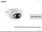
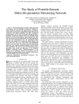
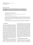
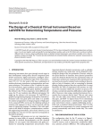
OPERATOR’S MANUAL Temporomandibular Joint Disorder Diagnostics System Team 5 Michael Jorgensen Kerry Semle Mariana Hu Client Information: Dr. Mark Litt University of Connecticut Health Center 263 Farmington Avenue, Farmington, CT 06030 860-679-4680 Important Safety Instructions *** Please follow all safety instructions listed below and highlighted in this manual. Failure to do so may result in personal injury and harm to others. The University of Connecticut, the students involved in the design and fabrication of this product, nor the client assume responsibility for personal injury due to negligence. Please use this device responsibly. *** Plug the device into a surge protector outlet; do not plug directly into a wall outlet; only use this device with 120 VAC 60 Hz power (standard in United States) Do not tangle the electrode leads Ensure that the electrode leads do not wrap around the user’s neck or appendages that may result in strangulation or bloody supply deprivation Do not use this product near water or other liquids; Do not consume water or accidentally spill liquids on the headband components Position the enclosure and laptop on a dry, stable surface Do not attempt to rewire the internal components of the device unless instructed to do so by descriptions laid out in this manual (for troubleshooting purposes only) Plug all leads and cables securely into the device. During data acquisition do not disconnect any leads or cables Use only approved electrodes and components provided by this manual. For part reordering, please order recommended components If the device is suspected to be faulty (LED not lit when on, excessive heat buildup in enclosure), turn the device off, wait five minutes, then turn the device back on. If the problem persists, do not use the device and refer to the ‘Troubleshooting’ section of this manual Handle the TMJD Diagnostics Device with care; do not accidentally drop or shake the circuit enclosure – doing so may disconnect internal components and may damage the device Temporomandibular Joint Disorder Diagnostics System Senior Design Spring 2011 1 Parts and Accessories Figure 1. TMJD Diagnostics System Figure 2. Circuit enclosure Temporomandibular Joint Disorder Diagnostics System Senior Design Spring 2011 2 Figure 3. USB 6008 DAQ (RED), Printed Circuit Board (BLUE) Figure 4. DIN Power Connector Temporomandibular Joint Disorder Diagnostics System Senior Design Spring 2011 3 Figure 5. Power Indicator LED Figure 6. Power Switch Temporomandibular Joint Disorder Diagnostics System Senior Design Spring 2011 4 Figure 7. Printed Circuit Board Figure 8. Transformer Temporomandibular Joint Disorder Diagnostics System Senior Design Spring 2011 5 Figure 9. USB (A to B) Cable Figure 10. Neuroband Data Acquisition Unit Temporomandibular Joint Disorder Diagnostics System Senior Design Spring 2011 6 Figure 11. Laptop (running LabVIEW program) Temporomandibular Joint Disorder Diagnostics System Senior Design Spring 2011 7 Figure 12. Alcohol Prep Pads Figure 13. Signa Electrode Gel Temporomandibular Joint Disorder Diagnostics System Senior Design Spring 2011 8 Features The diagnostics device allows the user to sleep in the comfort of their home. It eliminates the need for a sleep lab. The laptop computer, circuit enclosure, Neuroband Data Acquisition Unit, and power cord can all fit into a computer carrying case. This makes the design very portable. The laptop computer is equipped with a LabVIEW program that is user friendly for both the clinician and the patient. It features separate screens for the clinician and patient. The patient’s screen in LabVIEW shows an LED light that indicates that the program is acquiring EMG signals. The patient only has to enter the threshold specified by the clinician and proceed to sleep. The clinician’s screen in LabVIEW allows the clinician to view the saved EMG signals, the rectified signals, RMS signals as well as tabulated data. The Neuroband data acquisition unit is compatible with CPAP devices for sleep apnea treatment. It is also easy to use and washable. For more information on this device, please go to: https://www.bme.uconn.edu/sendes/Spring11/Team5/index.htm Table of Contents Section 1. Introduction 1.1 General overview of device 1.2 Instructions for use 2. Maintenance 3. Technical Description 4. Troubleshooting 5. References and further reading Page Number 9 9 10 29 30 48 53 1. Introduction 1.1 General overview of device The TMJD Diagnostics Device utilizes electromyography (EMG) to obtain biosignals from the muscles involved in mastication, including the left and right temporalis muscles, and the left and right masseter muscles. The EMG signals will be acquired during sleep time and will be viewed by the clinician to determine whether bruxism is present. Bruxism is characterized by clenching of the jaw and grinding of the teeth, and is the primary cause of temporomandibular joint disorder (TMJD). Temporomandibular Joint Disorder Diagnostics System Senior Design Spring 2011 9 Currently, EMG is utilized in sleep studies, which require the patient to stay overnight. Although these studies are accurate and effective in diagnosing TMJD, they are expensive and uncomfortable for the patient. Moreover, the EMG data is not consistent from the natural sleeping habits. This device introduces an improvement in the screening and diagnosis of TMJD by allowing the patient to perform an EMG study at the comfort of home while maintaining the accuracy of the sleep studies. The EMG signals are obtained from disposable electrodes with integrated gel and snap-on connectors that can easily be pushed on or removed from the electrode leads. These will be placed over the muscles of mastication. Since these electrodes eliminate the need of using extra adhesive gel, they provide optimal comfort to the patient. The wearable Neuroband houses the snap electrode leads that secure the disposable electrodes in this device. The snap electrode leads are removable so that the device can be washed between uses. Velcro® is utilized to allow for minor adjustments and achieve an optimal fit. The electrode leads are connected to a DIN connector cable attached to the circuitry using a D-sub connector. The circuit is enclosed and is connected via USB to the laptop computer. Pressing the power switch of the circuit enclosure will light up a green light, indicating that the device is powered on. The EMG signals are sent serially to a laptop computer. The user will run an executable LabVIEW program after the computer is powered on. The interface is userfriendly and provides sufficient help information in addition to a detailed user manual. The user will simply enter the values of threshold indicated by the clinician and begin the data acquisition. The program displays the signals acquired in real time. At the same time, relevant EMG data is recorded and the raw data is processed into useful diagnostic information that is presented to the clinician. These include the number of bruxing events detected in each muscle, the total duration of these events and specific times at which these events occur. 1.2 Instructions for use The following instructions assume that the user is conducting electromyography tests during sleep. Circuit and Laptop Preparation: Temporomandibular Joint Disorder Diagnostics System Senior Design Spring 2011 10 1. Place the circuit enclosure FIG. 2 on a dry, stable surface near the user as shown in FIG 14. Figure 14. Circuit enclosure on dry, stable surface 2. Place the laptop close to the circuit enclosure as shown in FIG. 15. Do not have any liquids around the circuit enclosure or laptop as accidental spillage could permanently damage the components. Temporomandibular Joint Disorder Diagnostics System Senior Design Spring 2011 11 Figure 15. Laptop proximity to circuit enclosure 3. Connect the circuit enclosure to the laptop with the USB A to B cable as shown in FIG. 16. Temporomandibular Joint Disorder Diagnostics System Senior Design Spring 2011 12 Figure 16. USB connection from circuit enclosure to computer Figure17. USB connection to circuit enclosure 4. Connect the transformer to a certified surge protector and turn the surge protector. Note that the transformer may be connected directly to a wall outlet but it is highly advisable to connect it to a surge protector to prevent a surge of current. 5. Connect the DIN connector of the transformer to the circuit enclosure as shown in FIG. 18. Do not yet power the device on. Temporomandibular Joint Disorder Diagnostics System Senior Design Spring 2011 13 Figure 18. Power connection to circuit enclosure Temporomandibular Joint Disorder Diagnostics System Senior Design Spring 2011 14 Figure 19. DIN connector for transformer connected to circuit enclosure 6. Connect the D-SUB connector of the Neuroband Data Acquisition Unit to the male DSUB connector of the circuit enclosure as shown in FIG. 20. Temporomandibular Joint Disorder Diagnostics System Senior Design Spring 2011 15 Figure 20. D-Sub connector to circuit enclosure – all wired connections made Figure 21. D-Sub connection interface Temporomandibular Joint Disorder Diagnostics System Senior Design Spring 2011 16 Neuroband Data Acquisition Unit Preparation: 7. Place two electrodes per muscle over the left and right masseter and left and right temporalis muscles (FIG 22). Place an additional electrode on the center of the forehead. Figure 22. Temporalis and Masseter muscles 8. Snap black electrode lead of the black Velcro- covered band to electrode on forehead. Wrap band around head and secure. 9. Hold chin strap so that the ends of the snap leads are coming out of it on the same side of the head as the end of the black lead on the headband. 10. Snap leads to electrodes already placed on muscles. Be sure to have the same color lead on both electrodes of each muscle. 11. Connect the lead ends to the DIN cable by assuring that yellow leads are plugged into “Y” ports, blue leads into “B” ports, red leads into “R” ports, green leads into “G” ports, and the black lead into a port marked with a black dot. 12. Connect the laptop power cord into the surge protector or regular wall outlet. 13. Connect the DC plug of the laptop power cord into the laptop as shown in FIG. 23. Note that the power cord must be plugged into the laptop at all times during a data acquisition session, as the battery life of the laptop is less than 10 hours and may Temporomandibular Joint Disorder Diagnostics System Senior Design Spring 2011 17 run out of power before the session has ended. In this event, all data will be corrupted and erased. Figure 23. Power connection to laptop 14. Power the laptop on by selecting the power button in the upper right hand corner of the laptop as shown in FIG. 24. Temporomandibular Joint Disorder Diagnostics System Senior Design Spring 2011 18 Figure 24. Power button on laptop 15. Log into the computer using the provided login instructions. 16. Power the circuit enclosure on by switching the power switch to ‘1’ as shown in FIG. 25. The power indication light should turn green as shown in FIG. 25. Temporomandibular Joint Disorder Diagnostics System Senior Design Spring 2011 19 Figure 25. Power switch to power on circuit enclosure 17. Run the TMJD Diagnostics App. LabVIEW Program Preparation 18. The TMJD Diagnostics Application will show the screen indicated in Figure 26. The green light indicates the program is running. The patient should follow the instructions on the screen. 19. Click the “Thresholds” tab to view the screen shown in Figure 27 and enter the values of threshold for each muscle, as indicated previously by the clinician. 20. For additional help, click the “Help” button. A dialog box will pop up to provide additional instructions, as shown in Figure 28. 21. Click the “Clinician View” tab to verify that signals are being displayed as in Figure 29 when clenching and grinding. Then, proceed to sleep. Temporomandibular Joint Disorder Diagnostics System Senior Design Spring 2011 20 22. After awaking, click the “Stop” button located in the upper middle of the screen to end data acquisition. The green light should turn dark green indicating that the program has stopped running. 23. Return the TMJD Diagnostics device to the clinician. 24. Figure 26. TMJD Diagnostics Application running. Temporomandibular Joint Disorder Diagnostics System Senior Design Spring 2011 21 Figure 27. Threshold tab of TMJD Diagnostics Application Temporomandibular Joint Disorder Diagnostics System Senior Design Spring 2011 22 Figure 28. TMJD Diagnostics Application showing the “Help” dialog box. Figure 29. Clinician View tab of TMJD Diagnostics Application The following instructions are for the clinician to view the results in the LabVIEW program. 1. Power the laptop on by selecting the power button in the upper right hand corner of the laptop. 2. Log into the computer using the provided login instructions. 3. Run the TMJD Results Application. 4. The program will show the screen illustrated in Figure 30. 5. Click on the icon of one of the four path controls. As shown in Figure 31, a dialog box will pop up to select a file to read. Temporomandibular Joint Disorder Diagnostics System Senior Design Spring 2011 23 6. Select the file corresponding to the same muscle as the one indicated on the path control by clicking on the name of the file. If the patient recorded data over several days, the file of the desired date can be selected. 7. Click the “OK” button to begin reading the file. As shown in Figure 32, the screen will show the EMG data corresponding to the muscle and date selected. 8. Repeat steps 5 to 7 for the three remaining muscles. The LabVIEW program will then display the EMG signals of all four muscles, as shown in Figure 33. 9. Click on the “Signal Analysis” tab for a view of the rectified EMG signals and the rms EMG signals, as shown in Figure 34. 10. Click on the “Tabulated results” tab in order to view a summary of the number of bruxing events of each muscle, the total time duration of the events and the specific times of occurrence of these events, as shown in Figure 35. 11. If desired, scroll through the EMG signal displays to observe the signal at the times of the events detected. 12. To select a different file to view, click on the icon of the path control again and select the new file to read. 13. To stop viewing the results, click on the “Stop” button located in the upper middle of the screen. 14. Power the laptop off and store in a dry, safe place until next use. Temporomandibular Joint Disorder Diagnostics System Senior Design Spring 2011 24 Figure 30. TMJD Results Application showing path controls, displays for the four muscles and the tabs for selecting Raw Data, Signal Analysis or Tabulated results. Temporomandibular Joint Disorder Diagnostics System Senior Design Spring 2011 25 Figure 31. TMJD Results Application showing dialog box to select file to read. Temporomandibular Joint Disorder Diagnostics System Senior Design Spring 2011 26 Figure 32. TMJD Results Application reading EMG file selected. Figure 33. TMJD Results Application reading EMG files from the four muscles. Temporomandibular Joint Disorder Diagnostics System Senior Design Spring 2011 27 Figure 34. Signal Analysis tab of the TMJD Results Application showing rectified EMG signals of the four muscles. Temporomandibular Joint Disorder Diagnostics System Senior Design Spring 2011 28 Figure 35. Signal Analysis tab of the TMJD Results Application showing rectified EMG signals of the four muscles. 2. Maintenance There is not a significant amount of maintenance required for the TMJD Diagnostics System. It was designed to be robust and have a long lifetime for the client. However, some methods for proper maintenance will be discussed herein. The circuit does not require any maintenance for proper use; however there are several preventative maintenance methods that should be followed for optimal use. Firstly, the user should never drop the device as this may permanently dislodge some circuitry components or wires and damage the device until maintenance is performed. The circuit was designed to survive falls of one to two feet, but was not tested past two feet due to concern that it would damage the device. If damage by fall is suspected, the informed user Temporomandibular Joint Disorder Diagnostics System Senior Design Spring 2011 29 should direct their attention to the “Troubleshooting” section of this manual to check operational and steady state voltages, as well as loose components. Secondly, the user should not use liquids around the TMJD Diagnostics System for similar reasons to fall damage. The circuit enclosure is somewhat waterproof if spilled upon, but will not be protected if submerged. If water damage is suspected, the informed user should again consult the “Troubleshooting” section of this manual to perform maintenance. The Neuroband Data Acquisition was also designed for durability and should not experience significant damage. If the snap electrode leads are damaged, they can be purchased from bio-medical.com at http://bio-medical.com/products/din-to-snap- emgeeg-leads-18-inch.html. These leads are durable, however, and should not experience any damage. If the Neuroband components themselves are damaged, they can be ordered from bio-medical.com as well. Ordering information is available on the home website. If minor damage occurs, the user may sew the Neuroband components as they see fit. 3. Technical Description The circuit schematic is shown in FIG. 36 and was constructed using ExpressPCB’s free software to create the PCB files necessary for manufacturing. A schematic file is available for viewing on the home website. Several schematics were also created in Multisim and are likewise viewable on the home website. Temporomandibular Joint Disorder Diagnostics System Senior Design Spring 2011 30 Figure 36. Circuit schematic The power to the circuit is provided by a PW300 series wall transformer manufactured by SL Power Electronics. This provides +12 V @ 5 A, +5V @ 4 A, and -12 V @ 500 mA. A split power supply is required for both the instrumentation amplifiers and the bandpass filter ICs. Because the power supply is a transformer, isolation from the 120 VAC 60 Hz power line is achieved. Thus, there is no galvanic connection between the patient and the power line voltages, ensuring a safe environment for the patient. A DPST switch isolates +12 V and -12V from the circuit, while the ground is always connected when the jack is plugged into the enclosure. Two capacitors are connected from +12 V and -12 V to ground to provide bypass coupling. This stabilizes the power supplied to the ICs and also reduces noise. Because capacitors block DC signals and pass AC signals, all DC signals remain at the +12 V and -12V potentials, whereas all AC signals are connected directly to ground. In addition to these two bypass capacitors, additional bypass capacitors are connected to each Temporomandibular Joint Disorder Diagnostics System Senior Design Spring 2011 31 IC (as close to the power pin as possible) to provide additional stabilization. These capacitors are named (C13, C14, C15, C16, and C17). The circuit is composed of four separate stages, one for each of the four facial muscles. Each stage follows the flow diagram of FIG. 37. EMG CIRCUIT FLOWCHART Electrodes Protection Circuitry Analysis, Storage, and Display LabVIEW Program Instrumentation Amplifier Notebook PC Bandpass Filter 25 Hz – 500 Hz USB 6008 DAQ Figure 37. EMG circuit flowchart The EMG signal is picked up by three Kendall Arbo adhesive electrodes. One electrode is for the positive signal, one for the negative signal, and the third electrode is for the reference (grounding). All three electrodes must be connected to the user in order for the circuit to properly function. Since the instrumentation amplifier is configured as a differential amplifier, the common mode rejection ratio will eliminate any common noise to each input. Without all three electrodes connected to the system, the EMG signal is susceptible to 60 Hz or other electromagnetic interference (EMI). Signa Electrode Gel (FIG. 13) may be applied to the electrodes to improve the signal quality if desired by the user. Tests were conducted and did not find any evidence to support that electrode gel improved the conductivity of the electrodes, thus it is up to the user to decide whether it is used. For optimal signal quality, the user should abrade the skin with Alcohol Prep Pads (FIG. 12) prior to electrode attachment. This step is not necessary, but it can improve the signal quality because the abrasive pads can remove scaly skin and reduce the impedance of the electrode-skin interface. Temporomandibular Joint Disorder Diagnostics System Senior Design Spring 2011 32 Protection circuitry is positioned prior to the instrumentation to prevent a surge of current to the patient. The FDH333 low leakage diodes have a turn-on voltage of 700 mV, therefore any voltage above this threshold will cause the diodes to conduct all current to ground. This configuration will not interfere with the signal quality because the EMG signal rarely exceeds a few milivolts. Thus, all EMG signals are allowed to pass through to the instrumentation amplifier, and since the diodes have low leakage characteristics, an insignificant amount of current will pass to ground. This configuration ensures maximum protection to the patient to significantly reduce the possibility of electric shock. The instrumentation amplifier is an AD620, which is a classic three-op-amp instrumentation amplifier conveniently packaged into one IC. A biopotential amplifier must have high input impedance, low output impedance, and a high CMRR. The AD620 instrumentation amplifier from Analog Devices was selected because it is a low cost, high accuracy instrumentation amplifier with gains from 1 to 10,000 set by one external resistor. Its low noise, low input bias current, and low power makes it ideal for medical applications such as electromyography. The gain of the instrumentation amplifier was selected to be 330 (50.4 dB). The bandpass filter has a gain for four, so the total gain of the system is approximately 1320. This is sufficient for EMG amplification requirements. For troubleshooting purposes, pin 7 of each AD620 amplifier should be +12 V, pin 4 should be 12 V, and pin 5 should be GND. The facial muscle frequency bandwidth is approximately 25 Hz – 500 Hz (Cram, 1998). A TL074 low noise JFET quad amplifier was selected to act as the bandpass filter due to its high slew rate and low bias and offset currents. It is a common op amp for filtration purposes. The active filter is configured to be second order, which is sufficient to attenuate undesired noise. A 60 Hz filter was initially included in the design, but due to the high CMRR of the AD620 (~130 dB), most of the 60 Hz noise was attenuated and not visible in the output signal. The testing location has multiple EMI sources emitting 60 Hz noise including fluorescent lights, computers, power supplies, function generators, data acquisition devices, and other sources. However, the patient will likely be using this product in their bedroom or other environment where EMI is not a significant concern. Temporomandibular Joint Disorder Diagnostics System Senior Design Spring 2011 33 Additionally, a 60 Hz notch filter was configured in the LabVIEW program to attenuate and 60 Hz noise that does pass through to the output. Following the bandpass filters, coupling capacitors (C3, C6, C9, C12) are utilized to block DC signals and pass only AC signals. This removes the DC offset and ensures that the output only consists of the AC EMG signals. A capacitance of 0.1 μF with a ceramic disk capacitor was selected, but any capacitance value around this range is suitable. FIG. 38 shows an EMG signal from the left masseter following the bypass capacitor. Figure 38. EMG signal showing raw data FIG. 38 displays the raw EMG signal showing three muscle clenches. The horizontal (‘x’) axis of the graph displays the time at which the measurement was taken. This is important for diagnostics purposes because the time of bruxism can be detected, allowing Temporomandibular Joint Disorder Diagnostics System Senior Design Spring 2011 34 the clinician to visualize exactly when the patient is engaging in clenching or bruxing events. The vertical (‘y’) axis displays the amplitude of the EMG signal in volts. It can be seen from FIG. 38 that there is a level of baseline noise, which is mostly due to residual muscle contractions. The sensitivity of the TMJD Diagnostics System is comparable to that of current devices in industry (Cram), and therefore small muscle contractions can be amplified. If the level of baseline noise exceeds this level shown in FIG. 38, there may be a problem with the device, and the user should refer to the ‘Troubleshooting’ section of this manual. This may be a result of excessive EMI, or a fault with the system. The user may also view the signal analysis tab, which displays the rectified (FIG. 39) and RMS voltage (FIG. 40) signals. Figure 39. Rectified EMG signals Temporomandibular Joint Disorder Diagnostics System Senior Design Spring 2011 35 Figure 40. RMS voltage EMG signals It can be seen from FIGS. 38, 39, and 40 that the TMJD Diagnostics System is capable of acquiring accurate EMG data. The system was tested over a period of six hours, and the EMG data was consistent with short term tests. To simplify the diagnosis for clinicians, the raw EMG data is converted to tabular form to determine the number of bruxism events per muscle, the total time spent bruxing, and the exact times when the bruxing occurred. These results are shown in FIG. 41for a test of two clenches. Temporomandibular Joint Disorder Diagnostics System Senior Design Spring 2011 36 Figure 41. Tabulated data for easy diagnosis of bruxism It can be seen that the results of the tabulated results are relatively accurate. This method will eliminate the need for the clinician to review hours of EMG data and count the number of bruxism events. The algorithm for detection is relatively simple, but improvements can be made to increase the accuracy of bruxism detection. The client has been provided with LabVIEW 2010 development software, so changes to the code can be performed in the future. The patient will not have access to the code because the application will be an executable file prohibiting any program changes. Detailed Circuit Description Figure 42. shows one of the amplification/filtration circuits. The TMJD Diagnostics System is comprised of a total of four of these circuits to monitor the four facial muscles. Temporomandibular Joint Disorder Diagnostics System Senior Design Spring 2011 37 Figure 42. Amplification/filtration circuit for right masseter RM+, RM_REF, and RM-, are the electrode inputs, in this case, for the Right Masseter (RM). Diodes 1-4 provide the protection from electric shock. The AD620AN amplifies the EMG signals with a gain set with Rgain1. The gain equation provided by Analog Devices is given by . (1) If the user desires to increase the gain of the system, Rgain1 must be swapped with a lower resistance. Similarly, to decrease the gain of the system, Rgain1 must be swapped with a higher resistance. The gain of the instrumentation amplifier is set to 330, however the gain may be set anywhere between 1 and 10,000 depending on the user’s preference. To swap Rgain1 with a different value, the user must unscrew the circuit, unsolder Rgain1, and then re-solder the new resistance in its place. The user must be very careful to not accidentally disconnect any of the wires leading to the circuit. A simple way to decrease the resistance of Rgain1 and thus increase the gain of the system, is to solder a resistor in parallel with Rgain1. The parallel resistor may be selected by , Temporomandibular Joint Disorder Diagnostics System (2) Senior Design Spring 2011 38 where RTOTAL is the resulting resistance, and Ruser is the resistance selected by the user. This configuration will allow the user to increase the gain of the system without having to disconnect the circuit board and unsolder components. The four EMG signals are inputted to a National Instrument’s USB 6008 OEM data acquisition unit. This device has a 12 bit analog input resolution and is capable of up to 10,000 samples/second. For the TMJD Diagnostics System, a sampling rate of 1 kHz with 100 samples to read is sufficient to acquire the relatively slow EMG signals. The USB 6008 is then connected to the laptop for further processing in the LabVIEW program. Circuit Enclosure FIG. 43 shows a perspective view of the circuit enclosure highlighting the power inputs and outputs as well as the USB connection and D-Sub connector Figure 43. Circuit Enclosure [1] is the power cable input. The transformer must be connected to this by using the DIN connection provided. The power cable should be inserted all the way into [1] and Temporomandibular Joint Disorder Diagnostics System Senior Design Spring 2011 39 should not be loose. The user should not touch [1] when the power cable is inserted, and should also not touch the DIN power connector when the transformer is plugged into the wall. [2] is the power indication LED. This light will turn green when the power cable is plugged in and the switch [3] has been set to ‘I’ (on). [3] is the power switch. Set this switch to ‘I’ to turn the device on and set to ‘0’ to turn the device off. The circuit must be running at all times during the data acquisition session. Please do not power the device off during a data acquisition session, as this will distort the data and may cause an error with the TMJD Diagnostics System program. In the event that an error does occur due to accidental power outage, the existing data will be saved to a file, and the user should start a new session if desired. When the data acquisition session is complete, it is best to turn the stop the program on the computer, and then power off the circuit enclosure. [4] is the USB cable to connect to the laptop, and [5] is the lead connect to the electrodes, both of which will be discussed in more detail later in this manual. FIG. 44 shows the circuit enclosure with the cover removed to show the internal connections of the circuit. Temporomandibular Joint Disorder Diagnostics System Senior Design Spring 2011 40 Figure 44. Circuit enclosure with cover removed [1] is the USB 6008 data acquisition unit. This circuit acquires the processed data from circuit [2]. A green LED located at [1a] will blink approximately every second during proper operation. If this LED blinks at a different rate and there is a connection problem with the TMJD Diagnostics System, please disconnect the USB cable, power off the device, wait one minute, then reconnect the USB cable, power the device on, and resume your data acquisition session. If the problem persists, contact National Instruments toll-free customer service at (800) 531-5066. Printed Circuit Board The printed circuit board (PCB) schematic is shown in FIG. 45. Temporomandibular Joint Disorder Diagnostics System Senior Design Spring 2011 41 Figure 45. Printed Circuit Board The PCB was designed using ExpressPCB’s free PCB design software at www.expresspcb.com. A four layer PCB was designed so that the power and ground layers were sandwiched in between two signal layers. This configuration causes the power and ground layers to act as parallel plate capacitors to further reduce noise due to EMI. It also significantly reduces the size of the circuit and complexity of traces. The PCB following manufacturing is shown in FIG. 46. Temporomandibular Joint Disorder Diagnostics System Senior Design Spring 2011 42 Figure 46. PCB following manufacturing The 4-layer Miniboard manufacturing option was selected because the components fit within the specified dimensions. With the fixed size and quantity specified by ExpressPCB, the cost of PCB manufacturing was significantly reduced. The PCB schematic is available for download on the home website. Table 1 displays a component breakdown for each circuit. Part Value R1, R2, R3, R7, R8, R9, R13, R14, R15, R19, R20, R21 100 kΩ Price Each $ Quantity - Temporomandibular Joint Disorder Diagnostics System 12 Ext. Price $ - Usage Description Impedance resistors to electrodes Senior Design Spring 2011 43 D1, D2, D3, D4, D5, D6, D7, D8, D9, D10, D11, D12, D13, D14, D15, D16 FDH333 Diode $ 0.32 16 $ 5.18 R4, R10, R16, R22 150 Ω $ - 4 $ - C13, C14, C15, C16, C17 1 µF (electrolytic) $ - 5 $ - R5, R11, R17, R23 82 kΩ $ - 4 $ - Bandpass filter R6, R12, R18, R24 C1, C4, C7, C10 C2, C5, C8, C11 C3, C6, C9, C12 330 kΩ $ - 4 $ - Bandpass filter 0.1 µF 1 nF 0.1 µF $ $ $ - 4 4 4 $ $ $ - LED Green LED $ 0.11 1 $ 0.11 R_LED 220 Ω $ - 1 $ - Bandpass filter Bandpass filter Coupling capacitors Power indication LED Current-limiting resistor to LED U1, U2, U3, U4 AD620 $ 7.06 4 $ 28.24 U5 TL074 $ 0.65 1 $ 0.65 ADDITIONAL COMPONENTS: Part Value Price Each Quantity Ext. Price IC DIP socket 8 pin - $ 0.94 4 $ 3.76 IC DIP socket 14 pin Rocker DPST switch - $ 1.63 1 $ 1.63 - $ 6.26 1 $ 6.26 DIN Female Transformer - $ $ 1.63 86.58 1 1 $ $ 1.63 86.58 Enclosure - $ 7.20 1 $ 7.20 Temporomandibular Joint Disorder Diagnostics System Patient protection circuitry Gain resistors for instrumentation amplifier Power bypass coupling capacitors Instrumentation Amplifier Bandpass filter op amp Usage Description Socket for AD620s Socket for TL074 Power switch DC input Wall transformer Circuit Enclosure Senior Design Spring 2011 44 PCB - $ 40.73 1 TOTAL $ 40.73 Printed Circuit Board $ 181.97 Table 1. Budget breakdown for circuit components Data Acquisition To acquire data from the circuit and perform analog to digital conversion, the USB 6008 OEM from National Instruments was selected. It has 12 bit analog input resolution of 12 bits and has a maximum sampling rate of 10 kS/s, both of which satisfy the criteria of this project. Its maximum voltage range and minimum voltage accuracy are also suitable for EMG signal acquisition. The USB 6008 OEM is shown in FIG. 47. Figure 47. USB 6008 OEM DAQ from National Instruments The OEM model offers a low-cost alternative to data acquisition and USB interfaces to embedded designs. For the final product, it is contained within the circuit enclosure for ease of use for the patient. The USB 6008 was tested extensively and it acquires data similar to higher model PXI DAQ devices and completely satisfied the data acquisition requirements for the project. Temporomandibular Joint Disorder Diagnostics System Senior Design Spring 2011 45 Laptop The Dell Latitude E6410 (FIG. 48) is used to run the executable LabVIEW file. It is equipped with Windows 7, Intel Dual Core vPro 2.80 GHz processor, 4 GB RAM, 500 GB hard drive and a 14.1 inch widescreen display. The computer receives the electromyographic data from the circuit via the National Instruments’ USB 6008 OEM. Since the computer and the program will be running overnight, saving and processing a large amount of data, the 500 GB hard drive is optimal for this application. Figure 48. The Dell Latitude E6410 LabVIEW Program Two LabVIEW executable files run in the laptop. The TMJD Diagnostics Application will be run by the patient before sleeping. A green LED indicates that the program is running. After entering the values of threshold specified by the clinician, data acquisition begins as the patient proceeds to sleep. The program acquires the data through the DAQ Assistant and splits the signals into the four different muscles for display, analysis and storage. Temporomandibular Joint Disorder Diagnostics System Senior Design Spring 2011 46 Throughout the period of time during which the patient is sleeping, the program displays the EMG signals in real time. Only when the value of the EMG signal exceeds the threshold preselected, indicating relevant muscle activity, a portion of the signal is written to the file corresponding to that specific muscle. This way, we save memory by not storing data when bruxism events are not present. The Stop button will end the data acquisition. When the patient returns the device to the clinician, he is able to view the EMG data saved. Using a path control, the clinician selects which muscle’s activity he wants to view and the date. The program also offers the rectified EMG view, the rms view and tabulated data. These include total number of bruxing events of each muscle, total duration of these events and the exact times of occurrence of these events. Moreover, the scrollbars allow the clinician to scroll over the EMG signal to analyze it during the times the events are detected. Fig 49 and 50 display the flow charts that describe the functionality of the TMJD Diagnostics Application and the TMJD Results Application, respectively. Fig 49. Flowchart of the functionality of TMJD Diagnostics Application Temporomandibular Joint Disorder Diagnostics System Senior Design Spring 2011 47 Fig 50. Flowchart of the functionality of the TMJD Results Application 4. Troubleshooting *** All troubleshooting methods requiring the user to visually inspect or alter the internal circuitry of this device assumes the user to be capable of safely performing such tasks and should conduct such tasks with the power to the device off. These methods should be performed only by the owner of the TMJD Diagnostics System if they deem the repair necessary to the proper functioning of the device. *** Signal Display Errors: Problem: ECG crosstalk Figure 51. EMG signal contaminated with ECG artifact Temporomandibular Joint Disorder Diagnostics System Senior Design Spring 2011 48 Solution: It is possible, however unlikely, to witness electrocardiography (ECG) artifact in the EMG signal. The QRS complex may be visible, as shown in FIG. 51. Signal averaging may be necessary to eliminate ECG artifact. Because this problem is so rare, the user cannot select a signal averaging option. This must be added in the code of the program if it is necessary to average the signal. If ECG artifact persists, indwelling electrodes may be considered, but will cause significant discomfort to the patient. Problem: EEG artifact Solution: EEG signals may be picked up by the surface electrodes due to the proximity of the facial muscles to the brain. Since EEG signals exist at low frequencies (most less than 20 Hz), the user may select a higher ‘low cutoff frequency’ with the Filter Selection tool in the program. For example, a filter of 25-500 Hz should attenuate most EEG artifact. If artifact persists, a filter of 100 – 500 Hz should solve the problem. This problem is rare because there is an analog filter that attenuates frequencies less than 25 Hz. Problem: AC Line Interference Figure 52. AC line interference effect on EMG signal Solution: Excessive AC line interference may be a result of several sources. To reduce this type of interference, please ensure the following points are met: Temporomandibular Joint Disorder Diagnostics System Senior Design Spring 2011 49 1. Keep the device away from fluorescent lighting 2. Keep the device away from electronic devices and power cords 3. Check to make sure that power cords do not cross the leads 4. Check to make sure that all leads are connected to the device 5. Move the device away from the wall and other noisy sources (appliances, heater units, etc.) If the previous steps have been taken and AC line interference is still evident, turn off the TMJD Diagnostics System, restart the computer, wait five minutes, then power the TMJD Diagnostics System on again and resume your session. Problem: DC offset (baseline not at 0 Volts) Figure 53. DC offset effect on EMG signal Solution: 1. Remove electrodes that may be loose or have a poor connection 2. Use an alcohol pad to cleanse the area and carefully abrade the skin 3. Wait one minute for the alcohol to dry, then reapply electrode while ensuring maximum adhesion 4. If the problem still persists, check to make sure that all leads are connected to the device and that no leads are moving during measurement. Problem: Movement artifact Temporomandibular Joint Disorder Diagnostics System Senior Design Spring 2011 50 Figure 54. Effect of movement artifact on EMG signal Solution: Consider using medical tape (ex. 3MTM Micropore Medical Tape) to affix leads to the user or a nearby stable structure. This will reduce the strain against the electrodes during movement and will help to reduce artifact in the signal. Additionally, please avoid rapid movements that might displace the leads. General Errors: Problem: Excessive heat buildup in circuit enclosure (unit is hot to the touch) Solution: 1. Power the device off 2. Disconnect the power cord from circuit enclosure 3. Disconnect the USB cable from circuit enclosure 4. Wait 5-10 minutes 5. Reconnect the power cord and USB cable 6. Make sure all cables are inserted properly 7. Power the device on and observe for heat buildup 8. If the problem persists, disconnect the cover from the circuit enclosure with power OFF, and visually inspect for loose wires, shorted connections, etc. 9. If the problem still persists, return unit to owner for further inspection Problem: LED does not turn on when switch set to ‘I’ Temporomandibular Joint Disorder Diagnostics System Senior Design Spring 2011 51 Solution: 1. Power the device off 2. Disconnect the power cord from circuit enclosure 3. Disconnect the USB cable from circuit enclosure 4. Wait 5-10 minutes 5. Reconnect the power cord and USB cable 6. Make sure all cables are inserted properly 7. Power the device on 8. If the problem persists, disconnect the cover from the circuit enclosure with power OFF, and visually inspect for loose wires, shorted connections, etc. 9. If the problem still persists, return unit to owner for further inspection Problem: No data acquired when USB cable is plugged in Solution: 1. Make sure the power cord is plugged into the circuit enclosure and the switch is set to ‘I’ to turn the device on; the power indicator LED should emit green 2. Make sure the USB cable is securely connected to the USB ‘A’ port on the circuit enclosure 3. Switch the USB cable to a different USB jack on the laptop; the USB port must be USB 2.0 and must be capable of providing power to the USB 6008 DAQ 4. Ensure that the LabVIEW program is running properly; close all background applications that may interfere with the processing of the LabVIEW program 5. If problem persists, restart the computer and re-open the LabVIEW program to initiate a new session Temporomandibular Joint Disorder Diagnostics System Senior Design Spring 2011 52 References and Further Reading Cram, Jeffrey. Introduction to Surface Electromyography. 1st. Jones & Bartlett Publishers, 1998. Print. Crider, Andrew, Alan G. Glaros, and Richard N. Gevirtz. "Efficacy of Biofeedback-Based Treatments for Temporomandibular Disorders." Applied Psychophysiology and Biofeedback 30.4 (2005): 333-45. Print. Doering, S., J. A. Boeckmann, S. Hugger, and P. Young. "Ambulatory Polysymnography for the Assessment of Sleep Bruxism." Journal of Oral Rehabilitation 35 (2008): 572-76. Print. Galaros, A. G., Z. Owais, and L. Lausten. "Reduction in Parafunctional Activity: a Potential Mechanism for the Effectiveness of Splint Therapy." Journal of Oral Rehabilitation 34 (2007): 97-104. Print. Galaros, Alan G., Karen Williams, and Leonard Lausten. "Diurinal Variation in Pain Reports in Temporomandibular Disorder Patients and Control Subjects." Journal of Orofacial Pain 22.2 (2008): 115-21. Print. Gallo, Luigi M., Gilles Lavigne, Pierre Rompre, and Sandro Palla. "Reliability of Scoring EMG Orofacial Events: Polysymnography Compared with Ambulatory Recordings." European Sleep Research Society 6 (1997): 259-63. Print. Kato, Takafumi, Norman M. Thie, Jacques Y. Montplaisir, and Gilles J. Lavigne. "Bruxism and Orofacial Movements During Sleep." Dental Clinics of North America 45.4 (2001): 657-84. Print. Philips Semiconductor, "UART to Bluetooth Interfacing." NXP Semiconductors. Philips 43 Kraus, Steven. Temporomandibular Disorders. 2nd ed. New York, NY: Churchill Livingstone Inc., 1994. Print. Robertson, Gordon. “Electromyography: Processing.” University of Ottawa, 05, 11 2007. Web. Apr 2011. www.health.uottawa.ca/biomech/courses/apa4311/emg-p2.pps. Webster, John. Medical Instrumentation Application and Design. 2nd ed. Boston, MA: Houghton Mifflin Company, 1992. Print. Temporomandibular Joint Disorder Diagnostics System Senior Design Spring 2011 53