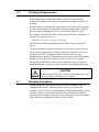
1
SmartTable® OTS™
User’s Manual
ii
iii
Warranty
Newport Corporation warrants that this product will be free from defects in
material and workmanship and will comply with Newport’s published
specifications at the time of sale for a period of one year from date of
shipment. If found to be defective during the warranty period, the product
will either be repaired or replaced at Newport's option.
To exercise this warranty, write or call your local Newport office or
representative, or contact Newport headquarters in Irvine, California. You
will be given prompt assistance and return instructions. Send the product,
freight prepaid, to the indicated service facility. Repairs will be made and the
instrument returned freight prepaid. Repaired products are warranted for the
remainder of the original warranty period or 90 days, whichever first occurs.
Limitation of Warranty
The above warranties do not apply to products which have been repaired or
modified without Newport’s written approval, or products subjected to
unusual physical, thermal or electrical stress, improper installation, misuse,
abuse, accident or negligence in use, storage, transportation or handling. This
warranty also does not apply to fuses, batteries, or damage from battery
leakage.
THIS WARRANTY IS IN LIEU OF ALL OTHER WARRANTIES,
EXPRESSED OR IMPLIED, INCLUDING ANY IMPLIED WARRANTY
OF MERCHANTABILITY OR FITNESS FOR A PARTICULAR USE.
NEWPORT CORPORATION SHALL NOT BE LIABLE FOR ANY
INDIRECT, SPECIAL, OR CONSEQUENTIAL DAMAGES RESULTING
FROM THE PURCHASE OR USE OF ITS PRODUCTS.
First printing 2009
© 2009 by Newport Corporation, Irvine, CA. All rights reserved. No part of
this manual may be reproduced or copied without the prior written approval
of Newport Corporation.
This manual has been provided for information only and product
specifications are subject to change without notice. Any change will be
reflected in future printings.
Newport Corporation
1791 Deere Avenue
Irvine, CA, 92606 USA
Part No. 90026760 Rev. B
iv
Table of Contents
Warranty................................................................................................ iii
Table of Contents .................................................................................. iv
List of Figures ....................................................................................... vi
Section 1 – General information
1.1
1.2
1.3
1.4
1.5
1.6
1.7
2
2.3
2.4
2.5
2.6
2.7
3
Introduction ...................................................................................7
Getting Started ...............................................................................7
Unpacking and Inspection .............................................................7
Safety Considerations ....................................................................7
System Placement ..........................................................................8
Air Supply Requirements ..............................................................9
Warranty Information ....................................................................9
Section 2 – Unpacking and Assembly
2.1
2.2
10
Unpacking and Inspecting ...........................................................10
OTS Frame Assembly .................................................................11
2.2.1 Installing Leveling Valves ...............................................15
2.2.2 Installing the Air Filter Regulator (ARF) ........................16
2.2.3 Connecting Air Lines ......................................................16
Squaring and Leveling the OTS Frame .......................................18
2.3.1 Leveling the OTS frame for the rigid (-N) and isolated
versions (-I) .....................................................................18
Installing the Table: .....................................................................19
Leveling the table on the frame ...................................................20
2.5.1 Leveling the Table on the Rigid (non-isolated - N) version
of the OTS System...........................................................20
2.5.2 Leveling the Table on the Rigid (isolated -I) version of
the OTS System ...............................................................22
Floating the Table ........................................................................22
Adjusting Leveling Valve Sensors ..............................................23
Section 3 – Operation
3.1
3.2
7
25
Principles of Operation ................................................................25
Performance Adjustments ...........................................................25
3.2.1 Stabilizing high center-of-mass loads .............................25
v
3.3
4
Section 4 – Troubleshooting
4.1
4.2
4.3
4.4
4.5
5
28
System Does Not Float ................................................................28
Poor Isolation Performance .........................................................28
System Oscillates.........................................................................29
System Leaks Air Constantly ......................................................29
Oil Leaking From Isolator ...........................................................29
Section 5 – Factory Service
5.1
6
3.2.2 Improving leveling response times ..................................26
3.2.3 Table loads and/or load positions change ........................26
Maintenance ................................................................................26
3.3.1 Cleaning ...........................................................................26
3.3.2 Air Quality .......................................................................27
30
Obtaining Factory Service ...........................................................30
Service Form
31
vi
List of Figures
Figure 1 OTS leg weldment with shipping bracket being removed ............ 12
Figure 2 OTS leg weldments and cross-brace positioning .......................... 12
Figure 3 Leveling valve mounting holes located on the cross brace should
be installed so they are positioned toward the top of the frame and
facing outward. ............................................................................. 13
Figure 4 Connecting cross-braces to OTS leg weldments .......................... 13
Figure 5 Tightening the cross-brace bolts to the leg weldment .................. 14
Figure 6 Completed OTS frame assembly .................................................. 14
Figure 7 Leveling valve location ................................................................. 15
Figure 8 Master Leveling valve installed on cross brace. ........................... 15
Figure 9 Location of Master-slave valve ..................................................... 16
Figure 10 Air regulator filter (ARF) being installed on leg weldment ......... 16
Figure 11 Pneumatic plumbing diagram for isolated version OTS system ... 17
Figure 12 Tubing connection for Master isolator .......................................... 17
Figure 13 Tubing connection for master-slave isolator................................. 18
Figure 14 Leveling the OTS frame................................................................ 19
Figure 15 Close up of leveling feet used to level the OTS frame ................. 19
Figure 16 Mounting hole pattern for attaching table to isolator.................... 20
Figure 17 Jack screw used to level the rigid OTS system ............................. 21
Figure 18 Leveling wrenches used for leveling the OTS rigid system ......... 21
Figure 19 Illustration showing positioning of leveling wrenches used for
leveling the OTS rigid system....................................................... 21
Figure 20 Safelock clip attachment ............................................................... 22
Figure 21 Close up of OTS isolator floating ................................................. 23
Figure 22 System stability diagram ............................................................... 26
7
Section 1 – General information
1.1
Introduction
The Newport SmartTable® OTS™ Vibration Isolation Workstation provides
an ideal working platform for vibration influenced devices such as
interferometers, microscopes, and balances. Sensitive instruments such as
these will show significant improvements in resolution and repeatability
when isolated from floor motion by the OTS pneumatic suspension system.
Special care was taken to ensure excellent performance in the 10-50 Hz floor
vibration frequency range corresponding to dominant ambient vibration
frequencies common to multi-floor buildings. The OTS pneumatic isolators
provide excellent protection against both vertical and horizontal floor
motions.
These workstations integrate Newport’s rigid, laminated honeycomb panel
SmartTable technology and pneumatic isolation systems to provide a
mounting platform which is rigid, yet thin and lightweight. The system
accommodates high-center of-gravity loads with exceptional stability.
Equipped with casters, the system is easy to move without heavy equipment.
It is possible to tailor the system to a wide variety of applications using the
range of sizes and the many optional storage and safety accessories.
1.2
Getting Started
Please read this instruction manual thoroughly before assembling the
isolation system. The individual components have been assembled at the
factory and require only final system assembly and performance adjustment.
1.3
Unpacking and Inspection
The components of your Newport Vibration Control System are packed in
individual, labeled boxes. Carefully inspect all components for shipping
damage.
Report any shipping damage immediately to Newport and the shipping
company.
1.4
Safety Considerations
The following terms are used in this manual that relate to your safety.
8
WARNING
Warning is used to indicate dangers that could result in personal
injury.
CAUTION
Caution is used to indicate situations that may result in damage
to components of your Newport Vibration Control System.
1.5
System Placement
To ensure optimal performance from your OTS Vibration Isolation System, it
should be located on a level surface. Uneven floors or mounting surfaces may
cause difficulty if their irregularity is outside of the range of the leveling feet.
The OTS isolators must be mounted so that its axis is not more than 0.5
degrees from vertical. This is necessary for the isolator to function properly
in the horizontal mode. Note: 0.5 degrees is equal to 0.05 (1.3 mm) inches in
6.0 inches which is the isolator base dimension. A typical spirit level will
easily measure 0.5 degrees and can be used to check the vertical alignment of
each isolator.
If the floor where the isolators are being mounted has a depression of more
than 0.05 inches under one side of the base, then the floor should be grouted
or shimmed level at this location.
If the system is not located on the ground floor of the building, it should be
located near primary vertical structures such as exterior walls or support
columns. By locating the table near these structures, the effects of low
frequency floor motion will be minimized, thus increasing isolator
performance. It is also advisable to avoid locations adjacent to major sources
of vibration from operating machinery such as elevators, air conditioning
plants, or factory equipment.
WARNING
The payload is attached to the isolators with bolts. In the event
of an earthquake, the system may collapse. For areas susceptible
to earthquakes, we recommend that earthquake restraints be
installed on each vibration control system.
9
1.6
Air Supply Requirements
A constant supply of air must be connected to the isolators during operation.
After initial setup and filling, the isolators consume air only when the
leveling valves adjust the pressure to compensate for changes in the load on
the table.
Bottled nitrogen or mechanically compressed air may be used. The required
pressure is determined by dividing the total load, including table weight, by
the total isolator diaphragm area (15.6 in2 per isolator) plus 5-10 psig.
For example, if the table plus load is 2850 pounds and will be mounted on 4
isolators, the required pressure is:
2850 lbs/(4*15.6 in2) + 10 psig = 55.6 psig.
Note that the maximum operating pressure for the system is 90 psig (6.3
kg/cm2).
The Newport Model ACMP air compressor is an extremely quiet source of
clean, pressure regulated air. If another compressor or plant air is used, the
Newport model ARF Air Regulator/Filter should be used to ensure
maintenance free operation. These filters prevent water and dirt from getting
into the leveling valves and causing the valves to fail due to clogging.
The supply should include a shut off valve so that the air may be shut off
during maintenance or extensive setup when the load is changed drastically.
CAUTION
Bottled carbon dioxide (CO2) is not recommended since “icing”
can occur during rapid filling of the isolators.
1.7
Warranty Information
Warranty information may be found on the page preceding the Table of
Contents in this manual. Should it become necessary to exercise the
warranty, contact your Newport representative to determine the proper course
of action. Newport Corporation maintains offices throughout the United
States and other locations worldwide. Refer to the back cover of this manual
for the addresses and telephone numbers of these offices.
10
2
2.1
Section 2 – Unpacking and
Assembly
Unpacking and Inspecting
Unpack the SmartTable OTS leg assemblies, the cross-braces and all of the
hardware. Inspect all of the parts for shipping damage. There are 2 different
versions of the OTS system; rigid and isolated. The parts shipped with your
SmartTable OTS vibration Isolation system are shown below.
Isolated (-I) Version
Rigid (-N) version
Description
OTS cross
braces and leg
weldments
Qty
3 braces, 2
leg
weldments
IPV Leveling
valve
3
ARF Air
regulator and
mounting
bracket
1
¼” translucent
air line tubing
40 feet
Tee connector
3
Safelock clips
and mounting
screws
12 sets
¼-20 7/8 Hex
head screws
24
Black flat
washer
¼” locking
washer
24
24
Description
OTS cross
braces and leg
weldments
1 1/8 open end
frame leveling
wrench
Safelock clips
and mounting
screws
Qty
3 braces, 2
leg
weldments
2
Isolator leveling
wrench
1
Hex head
screws
24
Black flat
washer
¼” locking
washer
24
7/16” wrench
1
Bubble level
1
12 sets
24
11
2.2
7/16” wrench
1
Bubble level
1
Tubing
mounting clips
10
1 1/8” open
end frame
leveling
wrench
Black hole
plugs
2
100
¼” Grey
tubing
40 feet
¼ NPT male
tubing adaptor
1
M5 x 0.8
SHCS
6 (36mm)
2 (10mm)
OTS Frame Assembly
The SmartTable OTS leg assemblies are shipped bolted together via two
shipping brackets. These brackets keep the OTS leg assemblies upright
during shipping so oil used for horizontal damping inside the isolator
chamber does not leak out.
CAUTION
Do not lay the leg assemblies on their side. Damping oil will
leak out of the assembly.
Remove the two shipping brackets using the 7/16” wrench included with your
OTS system. Each bracket has 4 bolts that must be removed.
12
Figure 1
OTS leg weldment with shipping bracket being removed
Figure 2
OTS leg weldments and cross-brace positioning
Roughly position the OTS leg assemblies. The distance between the
assemblies should be about the length of the cross-braces. Cross-brace
length is roughly 6, 8, 10 feet depending on the size of your system.
WARNING
Two people will be required to safely assemble the OTS frame.
Each cross-brace has 2 sets of holes drilled in it. These holes are used to
mount the leveling valves. Make sure the holes are pointing outward.
13
Additionally, make sure the holes are positioned toward the top of the isolator
(see figure 3)
Figure 3
Leveling valve mounting holes located on the cross brace should
be installed so they are positioned toward the top of the frame and facing outward.
Figure 4
Connecting cross-braces to OTS leg weldments
Bolt the cross braces, one at a time, to the OTS frame assembly using the
7/16” bolts, washers and lock washers provided with the OTS frame. Use
the 7/16” wrench to tighten the bolts to a torque of 6 ft-lbs.
14
.
Figure 5
Tightening the cross-brace bolts to the leg weldment
CAUTION
Do not over tighten. The bolts can be stripped if excessive force
is used. Tighten to a torque of 6 ft-lbs.
Figure 6
Completed OTS frame assembly
15
2.2.1
Installing Leveling Valves
If your frame is the non-isolated (-N) version you do not have leveling
valves. Please skip this section of the assembly instructions. Go to section
2.3.
If your OTS system is the isolated version (-I) three leveling valves will need
to be mounted to the cross braces. Note that only three leveling valves are
needed since three points define a plane. The diagram in figure 7 shows the
location for the leveling valves.
ARF
Leveling valve locations
Figure 7
Leveling valve location
Two sets of holes have been pre-drilled and tapped in the frame cross braces.
One set has been drilled in the leg weldment. Attach the leveling valves to
the frame via these holes and use a 4mm allen wrench to tighten the M-5
socket head cap screws that came with the leveling valves. See figure 7 for
valve location.
Mounted leveling valve
to frame cross brace
Figure 8
Master Leveling valve installed on cross brace.
16
leveling valve mounted
to leg weldment
Figure 9
2.2.2
Location of Master-slave valve
Installing the Air Filter Regulator (ARF)
Figure 10
Air regulator filter (ARF) being installed on leg weldment
Attach the ARF air regulator to the mounting bracket. Attach the mounting
bracket to the OTS leg assembly (figures 7 and 10). Use the 4mm allen
wrench to tighten the two M-5 socket head cap screws.
2.2.3
Connecting Air Lines
The IPV leveling valve is shown in Figure 12. Three valves are used in all
systems as only three points are required to determine a plane. The leveling
valve locations are selected such that they form the largest triangle possible
under the table. The larger the triangle, the more stable the system will be.
When two or more isolators are controlled by the same valve, they act as a
single large isolator supporting the table at the center of force of the several
isolators. The floating height of the system is determined at the valve
position.
17
Connect grey air lines to the isolators as shown in figures 11, 12 and 13.
When cutting tubing, be sure the ends are round and cut squarely. This is best
done with a single edge razor blade (scissors will deform the tubing, causing
leaks). The connections are detailed in Figures 11, 12 and 13.
Use translucent tubing to connect the air supply to the ARF.
connections are firm by tugging on the tube.
Be sure the
3 leveling
valves
Figure 11
Pneumatic plumbing diagram for isolated version OTS system
Sensor
Table Bottom
Control
Arm
Leveling
Valve
Control Arm
Adjustment
Screw
Air Supply Line
OTS
Frame
Grey Tubing
Attachment Screws
Figure 12
Barb Fitting
Metering Needle
Valve
Tubing connection for Master isolator
18
Leveling Valve
Elbow fitting
on isolator
Table Bottom
Grey Tubing
Figure 13
2.3
2.3.1
Air Supply Line
Tee fitting
Elbow fitting
on isolator
Tubing connection for master-slave isolator
Squaring and Leveling the OTS Frame
Leveling the OTS frame for the rigid (-N) and isolated
versions (-I)
Place the bubble level on the OTS frame as shown in figure 14. The level
measures if the frame is level in the X-Y plane. Use the 11/8” open end
wrenches provided to adjust the four leveling feet until the frame is level
(figure 15). One wrench is used to hold the lock nut while the other is used
to rotate the bolt. This will either raise or lower the table depending on the
direction the nut is rotated. Adjust the leveling feet until the frame is level.
19
Figure 14
Figure 15
2.4
Leveling the OTS frame
Close up of leveling feet used to level the OTS frame
Installing the Table:
WARNING
Payloads are heavy! Use a forklift or other appropriate
equipment. Be sure to use proper lifting procedures to avoid
severe personal injury.
With the OTS frame assembled and leveled as described in Section 2.2, raise
the table and position it above the OTS frame. Be sure the frame is correctly
positioned relative to the attachment holes provided in the bottom of the
table. See Figure 16.
20
Hole pattern on bottom of
table for attaching Safelock
clips
Figure 16
Mounting hole pattern for attaching table to isolator
CAUTION
When lowering the payload on to the isolators, do not allow the
payload to shift sideways. Doing so could damage the isolators.
Position the table so the bolt hole patterns line up over each isolator (see
figure 16). Slowly lower the table to within ½” of the OTS frame. Slight
adjustment of the OTS frame positioning may be necessary in order to
achieve proper alignment for the isolator and bolt hole pattern on the bottom
of the table.
2.5
2.5.1
Leveling the table on the frame
Leveling the Table on the Rigid (non-isolated - N) version of
the OTS System
Adjust the four leveling jack screws(Figure 17, 19) using the spanner
wrenche (figure 18) until the table top contacts evenly on all four of table
supports and does not rock when pressed down on at any of the four corners.
Make sure all 4 isolator leveling feet are still in contact with floor. The
isolated (-I) version of the OTS does not have or require this adjustment. Use
the Safelock clips and clip bolts to attach the table support to the table (see
figure 20 ). The opposite end of the spanner wrench used to adjust the jack
screw can be used to tighten these bolts.
21
Figure 17
Figure 18
Figure 19
Jack screw used to level the rigid OTS system
Leveling wrenches used for leveling the OTS rigid system
Illustration showing positioning of leveling wrenches used for
leveling the OTS rigid system
22
Figure 20
2.5.2
Safelock clip attachment
Leveling the Table on the Rigid (isolated -I) version of the
OTS System
Make sure the table is resting on all four table support plates and does not
rock when pressed down on at any of the four corners. If this is the case,
attach the Safelock™ clips as described in section 2.6.2, figure 20. Make
sure all 4 isolator leveling feet are still in contact with floor.
If the table is not in contact with all four support plates and rocks, adjust the
appropriate leveling foot until the table support is in contact with the bottom
of the table. Once all four support plates are in contact with the bottom of the
table and all four leveling feet are in contact with the floor use the Safelock
clips and clip bolts to attach the table support to the table (see figure 20 ).
The opposite end of the spanner wrench used to adjust the jack screw can be
used to tighten these bolts.
2.6
Floating the Table
1.
Close the metering needle valve (figure 12) on each isolator then open
it ½ turn.
2.
Turn on the air supply and adjust the regulator for the pressure
calculated using the formula given in Section 1.6. This pressure must
not exceed 90 psig (6.3 kg/cm2).
3.
Check all connections for leaks. Correct or repair any leaks before
proceeding. If the table does not float within several minutes, increase
the air pressure until the table floats or adjust the value height sensors
to hold the control arms further down. Confirm that the needle valves
are open ½ turn per isolator supplied. NOTE: If the table oscillates
after it floats, decrease the air pressure or close the needle valves
slightly. In clean room applications the “EXH” (exhaust) port on the
23
valves may be connected to the clean room vacuum system to capture
the valve exhaust. NOTE: Exhaust must be routed to a vacuum
system. Backpressure in the tubing will cause the exhaust air to leak
from the valve.
Payload support plate
¼” gap
Top of flange
Figure 21
2.7
Close up of OTS isolator floating
Adjusting Leveling Valve Sensors
1.
After the system floats, check the position of the payload support plate
for all isolators (see figure 21). The gap between the bottom of payload
support plate and the top of the flange should be about 1/4 inch
nominal (6 mm).
2.
Adjust the control arm adjustment acrew of each valve (Figure 12) as
required to obtain this gap. When all isolators are adjusted, re-check
the level of the payload. NOTE: this step should require only minor
adjustments. Do not move the small set screw near the pivot of the
valve control arm.
3.
Verify that the table is freely floating on the isolators. Move the table
gently from side-to-side about 1⁄8 inch. You should not encounter any
resistance. Re-check by moving the table up and down the same
amount. Again, there should be no restriction of movement.
4.
Push one corner of the table down approximately 1⁄8" and release it.
The table should return to the original position within less than 4
seconds. Response time may be adjusted as described in Section 3.2.2.
5.
If the table rocks back and forth (oscillates vertically) without settling
down close all of the needle valve adjustment screws. Then re-open
the screw by 1/8 to ¼ turn.
6.
In each corner of the table gently push down on the table top. The
table should lower and then return to its starting position. Gently push
up from the bottom of the table. The table should slightly rise then
return to its original position. If the table does not move freely either
24
up or down adjust the height adjustment screws in the leveling valves
until the table moves freely.
25
3
3.1
Section 3 – Operation
Principles of Operation
Newport Isolators provide one of the best methods of vibration isolation for
critical applications. The system operates on the principle of air pistons,
which are equivalent of soft springs. The main advantage of the Newport
system over other designs are low vertical resonant frequency with low
amplification at resonance (Q) and a Pendulum™ horizontal decoupling
system for effective isolation from low amplitude vibration.
The leveling valves provided with the system control the height of the table
to within ±0.01 inch (0.3mm) accuracy. This tolerance is adequate for most
applications. More accurate valves are available for specialized applications.
3.2
Performance Adjustments
Once the system is assembled and floating, it is possible to make minor
adjustments to suit your individual needs. These adjustments involve the
system air pressure, the control arms, and needle valves.
WARNING
Once the system is floating, keep fingers away from the area
between the support plate and the top of the isolators. Any
object between these points may be caught if the load or air
supply changes. Personal injury may result.
3.2.1
Stabilizing high center-of-mass loads
If your load has a high center of mass or if the load is particularly heavy, the
system may oscillate. In this case, lower the air pressure or close the needle
valves slightly. This may improve stability and reduce the oscillation or
“hunting”.
A rule of thumb for determining high center of gravity (C-G) system stability
is shown in Figure 3.1. If the combined center of gravity of the payload is
within the “stable region”, the system will be stable. If the combined C-G is
inside the “may be stable region”, the system may be stable. If the combined
C-G is outside both regions, the system will probably be unstable.
26
Figure 22
3.2.2
System stability diagram
Improving leveling response times
If the system is stable, the re-leveling response time may be decreased by
increasing the system pressure. In addition, the needle valves may be opened
until the system oscillates and then closed slightly. This is desirable if
components are moving over the surface of the table.
For systems where the loads are seldom changed, slower re-leveling may be
beneficial. This is accomplished by closing the needle valves slightly and/or
decreasing the system pressure.
All needle valves should be opened the same amount for each isolator that
they supply.
3.2.3
Table loads and/or load positions change
If the loads are moving or changing significantly, the control arms may
require adjustment. Each time the load is changed, check the relationship of
the support plate to the top of each isolator. If the desired 1⁄4 inch is not
maintained, adjust the overall system pressure and/or the sensor positions.
3.3
Maintenance
Newport Isolation Systems require little maintenance. No periodic
maintenance is required.
3.3.1
Cleaning
Newport isolators are painted, powder coated, or zinc plated steel. This
coated material is relatively corrosion resistant. It may be cleaned by
applying non-abrasive liquid household cleaner to a rag and wiping the
isolator. Avoid abrasive cleaners.
27
3.3.2
Air Quality
Oil, water, or debris in the air supply may contaminate the leveling valves or
isolator damping system and degrade performance. Use of the Newport
model ARF Air Regulator and Filter in the air supply will prevent this
occurrence. The filter does require occasional cleaning.
28
4
4.1
Section 4 – Troubleshooting
System Does Not Float
Use the following procedure if the system does not float, when pressure is
applied to the isolators.
4.2
1.
Ensure that the supply pressure is 5–10 psig (0.4–0.7 kg/cm2) above
the pressure reading of any of the leveling valves. If the load is
increased, the pressure should be increased to maintain the difference
between supply and valve pressure. Refer to Section 1.6.
2.
Check to see if all air lines are connected properly and the supply
pressure is adequate (see step A). Refer to Figures 10, 11 and 12.
3.
Be sure that the needle valves are not closed completely.
4.
Check each leveling valve for clogging. To do this, press the control
arm down. Air should flow into the isolator, accompanied by the
familiar sound of moving air. Repair or replace any clogged valve. Use
the ARF filter/regulator to prevent this situation.
Poor Isolation Performance
The following may lead to poor isolation performance of your system.
1.
Vibration may be transmitted to the table through direct physical
contact of equipment with external sources of vibration including
cables.
2.
Isolators that float too high, too low, or are not centered may conduct
floor vibration to the table top. Centered isolators will remain centered
unless the payload and isolators are moved relative to each other.
3.
Equipment on the payload may be vibrating at a resonant frequency of
other components. Improve the rigidity of the mounting for that
equipment or remove that item from the system.
4.
Air currents or pressure fluctuations may be disturbing components on
the payload.
29
4.3
System Oscillates
If the system oscillates or “hunts”, you may have a set up with a high center
of mass. Refer to the information in Section 3.2.1 or consult your Newport
representative or Newport Corporation for further assistance.
4.4
System Leaks Air Constantly
All Newport isolators and valves are pressure leak tested prior to shipment.
Check all tubing connections for leaks with soapy water. Tubing that is
crushed out of round or that is not cut squarely may not seal in the push-in
fittings. Use a single edge razor blade to cut the tubing cleanly. If testing with
soapy water indicates that either the isolator or valve are leaking contact
Newport Customer Service.
4.5
Oil Leaking From Isolator
Damping oil may leak from the isolator if it is inverted or tilted more than 45
degrees. Losses of less than 3 ml will not affect the isolator performance.
Total volume of damping oil per isolator is approximately 30 ml.
Contact Newport Corporation if oil must be replaced.
30
5
5.1
Section 5 – Factory Service
Obtaining Factory Service
To obtain information concerning factory service, contact Newport
Corporation or your Newport representative. Please have the following
information available.
1. Model number.
2. Purchase order number.
3. Complete description of the problem.
If components are to be returned to Newport Corporation, you will be given a
Return Number, which you should reference in your shipping documents.
Please fill out the service form located on the next page, and have the
information ready when contacting Newport Corporation. Include the
completed service form with any parts or components that are returned.
31
6
Service Form
Vibration Control Products
Name
RETURN AUTHORIZATION #
Company
(Please obtain prior to return of item)
Address
Country
Date
P.O. Number
Phone Number
Item(s) Being Returned:
Model #
Serial # (or manufacturing date)
Description
Reason for return of goods (please list any specific problems)
Please Describe the Problem:
(Attach additional sheets as necessary)
Where is the Equipment Installed?
(factory, controlled laboratory, out-of-doors, etc.)
Maximum Air Pressure available?
Regulated?
Yes No
Any additional information. (If special modifications have been made by the
user, please describe below).
32