1
TRIBHUVAN UNIVERSITY
INSTITUTE OF ENGINEERING
THAPATHALI CAMPUS
FINAL YEAR PROJECT REPORT ON
INTELLIGENT TRANSPORTATION SYSTEM
BY:
Anita Maharjan
(72851)
Laxmi KC
(72868)
Rasmi Wagle
(72876)
Rasu Shrestha
(72877)
SUBMITTED TO:
DEPARTMENT OF ELECTRONICS AND COMPUTER ENGINEERING
INSTITUTE OF ENGINEERING
THAPATHALI CAMPUS
KATHMANDU, NEPAL
Bhadra, 2071
TRIBHUVAN UNIVERSITY
INSTITUTE OF ENGINEERING
THAPATHALI CAMPUS
FINAL YEAR PROJECT REPORT ON
INTELLIGENT TRANSPORTATION SYSTEM
BY:
Anita Maharjan
(72851)
Laxmi KC
(72868)
Rasmi Wagle
(72876)
Rasu Shrestha
(72877)
THIS PROJECT WAS SUBMITTED TO THE DEPARTMENT OF
ELECTRONICS AND COMPUTER ENGINEERING, IOE, THAPATHALI
CAMPUS IN PARTIAL FULLFILLMENT OF THE REQUIREMENT FOR THE
BACHELOR’S DEGREE IN ELECTRONICS AND COMMUNICATION
ENGINEERING
DEPARTMENT OF ELECTRONICS AND COMPUTER ENGINEERING
INSTITUTE OF ENGINEERING
THAPATHALI CAMPUS
KATHMANDU, NEPAL
Bhadra, 2071
DEPARTMENT ACCEPTANCE
The project titled “Intelligent Transportation System” submitted by Anita
Maharjan, Laxmi KC, Rasmi Wagle and Rasu Shrestha in partial fulfillment
of the requirement for Bachelor’s Degree in Electronics and Communication
Engineering has been accepted as a bona-fide record of work carried out by them
for our department.
_____________________
Er. Janardan Bhatta
Head of Department
Department of Electronics and Computer Engineering
Institute of Engineering, Thapathali Campus
Kathmandu, Nepal
i
CERTIFICATE OF APPROVAL
The undersigned certify that they have read and recommended to the Department
of Electronics and Computer Engineering, Institute of Engineering, Thapathali
Campus, a final project work titled “Intelligent Transportation System”
submitted by Anita Maharjan, Laxmi KC, Rasmi Wagle and Rasu Shrestha in
partial fulfillment of the requirement for Bachelor’s Degree in Electronics and
Communication Engineering.
___________________
___________________
Project Supervisor
External Examiner
Er. Prasanna Kansakar
Prof. Dr. Subarna Shakya
Lecturer
Assistant Dean
Department of Electronics and
Institute of Engineering
Computer Engineering
Institute of Engineering,
Thapathali Campus
___________________
Project Co-ordinator
Er. Bikash Poudel
Lecturer
Department of Electronics and
Computer Engineering
Institute of Engineering,
Thapathali Campus
DATE OF APPROVAL: Bhadra, 2071
ii
COPYRIGHT ©
The author has agreed that the library, Department of Electronics and Computer
Engineering, Institute of Engineering, Thapathali Campus, may make this thesis
freely available for inspection. Moreover the author has agreed that the permission
for extensive copying of this project work for scholarly purpose may be granted
by the professor(s), who supervised the project work recorded herein or, in their
absence, by the Head of Department, wherein this thesis was done. It is
understood that the recognition will be given to the author of this thesis and to the
Department of Electronics and Computer Engineering, Thapathali Campus in any
use of the material of this thesis. Copying of publication or other use of this thesis
for financial gain without approval of the Department of Electronics and
Computer Engineering, Institute of Engineering, Thapathali Campus and author’s
written permission is prohibited.
Request for permission to copy or to make any use of the material in this project
in whole or part should be addressed to:
Head of Department
Department of Electronics and Computer Engineering
Institute of Engineering
Thapathali Campus
Kathmandu, Nepal
iii
ACKNOWLEDGEMENT
This project is the result of dedication and encouragement of many individuals.
Our sincere and heartfelt appreciation goes to all of them. We would like to
express our hearty gratitude to the Department of Electronics and Computer
Engineering, Thapathali Campus for providing us with the opportunity to do this
project.
We are thankful to Er. Janardan Bhatta, Head of Department, Department of
Electronics and Computer Engineering, Institute of Engineering, Thapathali
Campus for availing us with resources and continuous support that helped us to
carry out this project. We must acknowledge our obligation to our Project
Coordinator, Er. Bikash Poudel, for his valuable suggestions throughout the
project. We owe our debt of gratitude to our Project Supervisor Er. Prasanna
Kansakar, for supervising our task and constantly motivating us with ideas
regarding the project from the time of its inception. We also thank Prof. Dr.
Subarna Shakya for taking the time out of his hectic schedule to attend our final
defense in the capacity of External Examiner. Last but not the least, we are
obliged to everyone who suggested and supported us in course of our project from
the beginning to the end.
iv
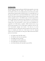
ABSTRACT
The project “Intelligent Transportation System” is an attempt to design a
tracking system that uses GPS to determine the precise location of a vehicle and
uses a GPRS connection implemented via a GSM modem to transmit location
information to a remote user. This system incorporates a hardware device installed
inside the vehicle termed in In-Vehicle Unit and a remote Tracking Server. This
information is transmitted to Tracking Server using GSM/GPRS modem by using
HTTP connection established with Tracking Server via GPRS. The Tracking
Server receives the location information and stores in Cloud Server database.
These information are available to authorized users of the system via website and
also by using mobile application.
Keywords: Intelligent Transportation System, GPS (Global Positioning
System), GPRS (General Packet Radio Service), GSM (Global System for
Mobile Communication), In-Vehicle Unit, Tracking Server, HTTP (Hyper Text
Transfer Protocol), Cloud Server
v
TABLE OF CONTENTS
DEPARTMENT ACCEPTANCE ........................................................................ i
CERTIFICATE OF APPROVAL ....................................................................... ii
COPYRIGHT © ................................................................................................... iii
ACKNOWLEDGEMENT ................................................................................... iv
ABSTRACT ............................................................................................................v
TABLE OF CONTENTS .................................................................................... vi
LIST OF FIGURES ............................................................................................. ix
LIST OF TABLES .................................................................................................x
LIST OF ABBREVIATIONS ............................................................................. xi
1.
INTRODUCTION.......................................................................................1
1.1.
Background ............................................................................................1
1.1.1.
Background Research ..................................................................... 1
1.2.
Problem Statement .................................................................................2
1.3.
Objectives ..............................................................................................3
1.4.
Scope .....................................................................................................3
1.5.
Project Summary ...................................................................................3
2.
LITERATURE REVIEW ..........................................................................5
3.
METHODOLOGY .....................................................................................7
3.1.
System Block Diagram ..........................................................................7
vi
4.
3.1.1.
In-Vehicle Unit ............................................................................... 8
3.1.2.
Tracking Server ............................................................................ 12
3.1.3.
Notice Board ................................................................................ 13
COMPONENTS AND TECHNIQUES...................................................16
4.1.
Hardware Implementation ...................................................................16
4.1.1.
LPC2148 Development Board ..................................................... 16
4.1.2.
GPS............................................................................................... 17
4.1.3.
GSM ............................................................................................. 20
4.1.4.
UART ........................................................................................... 22
4.1.5.
Liquid Crystal Display ................................................................. 23
4.2.
Software Implementation for Web ......................................................23
4.2.1.
ASP.NET MVC............................................................................ 23
4.2.2.
ASP.NET Web 2.0 ....................................................................... 24
4.2.3.
Microsoft Azure ........................................................................... 24
4.2.4.
Visual Studio 2013 ....................................................................... 25
4.2.5.
Web Hosting Service Provider (000webhost.com) ...................... 25
4.2.6.
Domain Name (.net76.net) ........................................................... 26
4.2.7.
HTML........................................................................................... 26
4.2.8.
JavaScript ..................................................................................... 26
4.2.9.
CSS ............................................................................................... 26
4.2.10.
Adobe Dreamweaver CS6 ........................................................ 27
vii
4.3.
5.
Software for Android Application development .................................27
4.3.1.
Eclipse ADT ................................................................................. 27
4.3.2.
XML ............................................................................................. 28
4.3.3.
JSON ............................................................................................ 28
TIME SCHEDULE AND COST .............................................................30
5.1.
Gantt Chart ..........................................................................................30
5.2.
Cost Description ..................................................................................31
6.
RESULT.....................................................................................................32
7.
APPLICATION.........................................................................................34
8.
PROBLEMS FACED ...............................................................................35
9.
LIMITATIONS AND FUTURE ENHANCEMENT .............................36
10. CONCLUSION .........................................................................................37
REFERENCES .....................................................................................................38
APPENDIX…………………………………………………………...................40
viii
LIST OF FIGURES
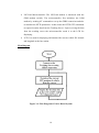
Figure 1.1: Block Diagram of the system ................................................................ 4
Figure 3.1: System Overview .................................................................................. 7
Figure 3.2: Flow Diagram of In Vehicle Unit........................................................ 10
Figure 3.3: Block Diagram of User Interface Unit ................................................ 12
Figure 3.4: Flow Diagram of Notice Board System .............................................. 14
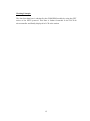
Figure 4.1: LPC2148 Development Board ............................................................ 16
Figure 4.2: Data obtained from GPS module using Flash Magic Terminal .......... 19
Figure 4.3: Interfacing of GPS module with LPC 2148 ........................................ 20
Figure 4.4: SIM900 GSM modem ......................................................................... 21
Figure 4.5: Interfacing of GSM modem with LPC 2148 ....................................... 21
Figure 5.1: Gantt Chart .......................................................................................... 30
ix
LIST OF TABLES
Table 4.1: Pin Out Function Description of GT-320R GPS module ..................... 18
Table 4.2: RMC Data format ................................................................................. 19
Table 5.1: Cost Description Table of the Project ................................................... 31
x
LIST OF ABBREVIATIONS
1G
:
First Generation
2G
:
Second Generation
ADC
:
Analog Digital Converter
ADT
:
Android Development Tools
AJAX
:
Asynchronous JavaScript And XML
API
:
Application Programming Interface
ASCII
:
American Standard Code for Information Interchange
ASP
:
Active Server Pages
AT
:
Attention
CAN
:
Controller Area Network
COM
:
Communication
CPU
:
Central Processing Unit
CS
:
Control Segment
CSS
:
Cascading Style Sheets
DBMS
:
Data Base Management System
DCS
:
Digital Cellular Service
DUART
:
Dual Universal Asynchronous Receiver/Transmitter
EDGE
:
Enhanced Data rates for GSM Evolution
EEPROM :
Electrically Erasable Programmable Read Only Memory
xi
EGNOS
:
European Geostationary Navigation Overlay Service
EGSM
:
Extended Global System for Mobile Communication
EIA
:
Electronics Industries Association
FTP
:
File Transfer Protocol
GND
:
Ground
GPRS
:
General Packet Radio Services
GPS
:
Global Positioning System
GSM
:
Global System for Mobile Communication
GUI
:
Graphical User Interface
HTML
:
Hyper Text Markup Language
HTTP
:
Hyper Text Transfer protocol
ID
:
Identification
IDE
:
Integrated Development Environment
IP
:
Internet Protocol
IMSI
:
International Mobile Subscriber Identity
ITS
:
Intelligent Transportation System
JS
:
JavaScript
JSON
:
JavaScript Object Notation
LCD
:
Liquid Crystal Display
LED
:
Light Emitting Display
LVTTL
:
Low Voltage Transistor Transistor Logic
xii
MHz
:
Mega Hertz
MVC
:
Model View Controller
NMEA
:
National Marine Electronics Association
OEM
:
Original Equipment Manufacturer
PC
:
Personal Computer
PCS
:
Personal Communication Service
PHP
:
Hypertext Preprocessor
PIN
:
Personal Identification Number
PSTN
:
Public Switched Telephone Network
RAM
:
Random Access Memory
RD
:
Receive Data
REST
:
Representational State Transfer
RF
:
Radio Frequency
RINEX
:
Receiver Independent Exchange Format
RISC
:
Reduced Instruction Set Computer
RMC
:
Recommended Minimum Sentence C
ROM
:
Read Only Memory
RS-232
:
Recommended Standard 232
RS-422
:
Recommended Standard 422
RS-485
:
Recommended Standard 485
RTCM
:
Radio Technical Commission for Maritime Services
xiii
SBAS
:
Satellite Based Augmentation System
SBS
:
Smart Bus System
SDK
:
Software Development Kit
SFTP
:
Secure File Transfer Protocol
SIM
:
Subscriber Identity/ Identification Module
SMS
:
Short Message Service
SQL
:
Structured Query Language
SRAM
:
Static Random Access Memory
SS
:
Space Segment
SVG
:
Scalable Vector Graphics
TD
:
Transmit Data
UART
:
Universal Asynchronous Receiver/Transmitter
UI
:
User Interface
URL
:
Uniform Resource Locator
US
:
User Segment
USART
:
Universal Synchronous/Asynchronous Receiver/Transmitter
USB
:
Universal Serial Bus
VB
:
Visual Basic
WAAS
:
Wide Area Augmentation System
XHTML
:
EXtensible HyperText Markup Language
XML
:
EXtensible Markup Language
xiv
1. INTRODUCTION
1.1. Background
The existing public transportation system in our country is troublesome for the
general public. There is no systematic provision for traffic routes and hardly any
vehicle arrives at a station on time. Under such circumstances people are
compelled to waste a good part of their busy schedules waiting for their buses to
arrive. The system, ‘Intelligent Transportation System’ seeks a solution to this
prevailing problem of public transportation in Nepal and focuses to make public
transportation systematic, dependable and easy to use. The design of this system
uses Global Positioning System (GPS) and Global System for Mobile
Communications (GSM) technologies. Each vehicle within the system is fitted
with an In-Vehicle unit which consists of a GPS module and a GSM modem
interfaced to microcontroller. The GPS module provides the location of the
vehicle and this information is sent to a web server via GSM network using GPRS
service. People can then access the location of the vehicle by logging into a
website through their mobile phone with internet accessibility and also by using
mobile application. The system is efficient, cost effective and useful in our
nation’s context. It provides a real time solution to the existing problem in public
transportation system.
1.1.1. Background Research
Different countries have carried out different projects on intelligent transportation
systems. Some of those projects have been taken as basis of research for our
project. Those projects are listed below.
GPS GSM Integration for Enhancing Public Transportation System: This
system design is based on Global Positioning System (GPS) and Global
System for Mobile Communications (GSM). The bus has an On-Board
module which consists of a GPS module and a GSM modem interfaced
with a microcontroller. GPS receiver identifies the location of the vehicle
1
and the information of the vehicle’s location is sent to a web server via
GSM network using SMS service. People can know the whereabouts of the
vehicle by logging into a website through their mobile phone with internet
accessibility [1].
Winnipeg Transit System: According to Winnipeg Transit System bus
riders in Winnipeg can access real-time bus schedule on the Winnipeg
Transit website, on their smart-phones, and via SMS text messages.
Winnipeg Transit’s Open Data Web Service provides a way for developers
to retrieve live information about Winnipeg Transit’s services [2].
1.2. Problem Statement
Nepal is a developing country and many aspects in the field of transportation
require improvement. Transportation is one of the most important infrastructures
for the general public. The day to day activities of the general public depends
upon quality of service provided by the public transportation system. Buses should
arrive at each station at the scheduled time, but the schedule may be affected by
certain unforeseeable occurrences such as traffic jams, road blocks, rallies etc. The
bus schedule is also affected by the mood/nature of the drivers - they may choose
to leave from the station either earlier or later than the scheduled time. Thus,
people are compelled to waste a good part of their busy schedules waiting for their
buses to arrive. So, it is necessary that public transport users know when buses
will arrive so that they can manage their schedules to meet with the bus' schedule.
There is also need of a control system that monitors the movement of vehicles at
the station to ensure that buses do not queue up at the bus station resulting in a
traffic jam. In order to solve these problems, there is need of a "Vehicle Tracking
System" which helps in systemizing public transportation system making it more
effective and efficient.
2
1.3. Objectives
The project objectives are listed as below:
To develop an accurate vehicular tracking system to monitor and manage a
public transportation system.
To provide commuters with exact location and estimated schedule of buses
through notification board at bus stops or more conveniently through a
website and an android application.
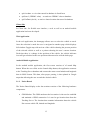
1.4. Scope
Tracking systems have widespread scope in many different fields all over the
world. Our project is constrained to the tracking of public vehicles for improving
the public transportation experience for the general public, but the concept of
tracking systems is very vast and finds application in many areas such as animal
tracking - including both pets and wild animals to know their whereabouts
continuously as well as to protect the endangered species against their poaching.
Tracking systems can also be used as a security system for elderly people to track
their movements by constant monitoring. Such systems may be even implemented
in accident detection of vehicles so that immediate action can be taken. Also,
private vehicles can be tracked in case of theft. Additionally, very important
transportation systems like school/college buses, ambulances etc. can be kept
under constant monitoring. Similarly, cargo trucks and truck carrying petrol and
diesel for the purpose of export and import can also be tracked to know when and
where the trucks stop and for how much time.
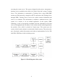
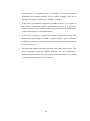
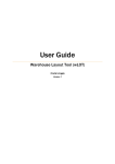
1.5. Project Summary
The project “ Intelligent Transportation System”
is an attempt to design a
tracking unit that uses GPS to determine the precise location of a vehicle.
This information is then conveyed to a remote server through a GSM modem
using GPRS connection. The end user can view the location of the vehicle by
3
accessing the remote server. The system, designed in this project, incorporates a
hardware device installed in the vehicle (In-Vehicle Unit) and a remote Tracking
Server. The information is transmitted to Tracking Server using GSM/GPRS
modem on GSM network by using direct HTTP connection with Tracking Server
through GPRS. Tracking Server receives the vehicle location information and
stores it in a database. This information is available to authorized users of the
system via a website or via an android application. In this system, GPRS
technology is used to forward the coordinates and time information to the data
server at a designated static IP address. In the website and the android application,
the position of the vehicle is plotted on Google maps. This system gives the
current vehicle location whenever needed with reliable accuracy. This project also
gives functional, technical description and software implementation for the GPS
and GSM/ GPRS based vehicle tracking system.
Figure 1.1: Block Diagram of the system
4
2. LITERATURE REVIEW
Vehicle Tracking Systems are developed and deployed in numerous
environments. These systems are capable of transmitting vehicle’s location
information and other custom parameters. In this project, we present the design
and implementation of a system that incorporates a hardware device installed in
the vehicle and a remote data center with tracking sever and a web application
with Google Maps API to plot the trail of the vehicle. The vehicle’s location is
determined using GPS, while the transmission mechanism can be satellite,
terrestrial radio or cellular connection from the vehicle to a radio receiver, satellite
or nearby cell tower. Once the positioning data is collected, it is transmitted
through a wireless communication system. The most economical viable service
used for this purpose is GSM/GPRS. In this project, we briefly describe the
architecture and implementation of a Vehicle Tracking Systems using GPS for
positioning information and GSM/GPRS for transmission of the information. The
design and implementation of the system includes acquisition and transmission of
vehicle’s location information and idling information to the data center/tracking
server.
Vehicle tracking and security applications using GPS and GSM technology have
been invented and implemented in different geographical locations serving
different applications. The use of GPS enabled vehicles has made life easy as one
can get to an unknown place with no help of others. Different projects concerning
vehicle tracking are proposed and are implemented intending to make
transportation and navigation easier, effective and systematic. So far sufficient
research has not been carried out in this topic in Nepal. Our project is an attempt
to make public transportation somewhat regulated and user friendly. A similar
project was carried out by the students of the University of Victoria titled “Design
a Smart Bus System” where the students have explored ideas of integrating the
Victoria Regional Transit
System
with
appropriate
communication
technologies and developing a corresponding smart-phone application. In the
SBS, users can access real-time passenger information such as schedules, trip
planners, bus capacity estimates, bike rack availability and bus stop
5
locations, using their smart-phones or their computers at bus stops. This system is
inclusive to all users including people with special needs. Here, the GPS is used to
obtain the current location of the bus and the obtained location in latitude and the
longitude is conveyed to the central server using GSM. The end user can obtain
this information by logging into the server. Beside this, the data is also transmitted
to the bus station where it is displayed in the LCD [3].
6
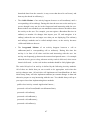
3.
METHODOLOGY
3.1.
System Block Diagram
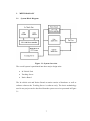
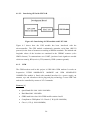
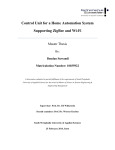
Figure 3.1: System Overview
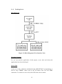
The overall system is partitioned into three major design units:
In-Vehicle Unit
Tracking Server
Notice Board
The In-vehicle unit and Notice Board at station consist of hardware as well as
software whereas the Tracking Server is software only. The basic methodology
used in our project can be described from the system overview presented in Figure
3.1.
7
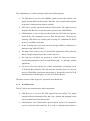
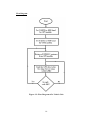
The methodology of vehicle tracking includes the following steps:
The GPS Receiver receives the GPRMC signal sent from the satellite. The
signal contains different information like date, time, latitude and longitude
at the time of transmission from the satellite.
LPC2148 is serially interfaced with the GPS module. The signal received
from the GPS Receiver is decoded and is passed to the GSM Modem.
GSM Modem is also serially interfaced with the LPC2148 and operates
based on the AT command it receives from the processor. The processor
sends the GPS data to the Tracking Server using AT commands for HTTP
protocol via GPRS connection.
In the Tracking Server the data received through GPRS is collected in a
database using ASP.NET.MVC.
The data is then retrieved by web and mobile applications which plots the
data in Google maps and presents it to the end user.
The end user can know the position of vehicle by using web browser
(intelligenttransportation.net76.net/final/index2.php) or through android
application.
For users at the bus stations, the vehicle information is displayed on an
LCD Notice Board display. The data from the Tracking Server is retrieved
using a GSM/GPRS connection and the data is forwarded to the LPC2148
microcontroller which displays it in the LCD Notice Board.
The three sections of this project are separately described below:
3.1.1. In-Vehicle Unit
The In-Vehicle unit contains three main components.
GPS Receiver: It receives the GPS signal from the satellite. The signal
contains different information like date, time, latitude and longitude at the
time of transmission from the satellite.
GSM Modem: The GSM modem operates based on the AT command it
receives from the microcontroller. It is used to establish and maintain a
8
connection with the Tracking Server using HTTP protocol over a GPRS
connection.
LPC2148 microcontroller: It is serially interfaced with both the GPS
module and the GSM modem. The LPC2148 microcontroller processes the
location information received from the GPS receiver and sends it to the
Tracking server using HTTP protocol via GPRS connection established
using the GSM modem.
LCD: The LCD is used for displaying the current position of the vehicle.
9
Flow Diagram
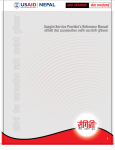
Figure 3.2: Flow Diagram of In Vehicle Unit
10
Working Principle
The GPS module, interfaced serially to the LPC2148 microcontroller, receives the
location information from the satellite. The received data is sent to the
microcontroller serially at a rate of 4800 baud. The received data can be selected
among different formats like RMC, RINEX, RTCM SC-104, and NMEA 0813. In
this project the RMC format is used and the $GPRMC data is read from the GPS
module. This format contains different information like Universal Time Constant,
Latitude, Longitude, Speed, etc. The GPRMC string is read by the microcontroller
from the GPS module and is transferred to the Tracking Server via HTTP protocol
over a GPRS connection made using the GSM modem. For connecting with the
Tracking Server, the microcontroller is used to send several initialization AT
commands to the GSM modem to establish a GPRS connection and to set up
HTTP protocol parameters [4]. The GSM modem communicates with the LPC
2148 microcontroller through serial interface. The baud rate for serial
communication between GSM modem and microcontroller can be altered. In this
project, for simplicity the default rate of 9600 baud is used. The command
sequence sent to the GSM modem for setting up the GPRS connection and HTTP
protocol are listed below:
AT+CPIN(to check if the SIM is ready)
AT+CREG?(to check network registration)
AT+SAPBR (for bearer checking)
AT+HTTPINIT (for HTTP initialization).
AT+HTTPPARA(to set HTTP parameter)
AT+HTTPACTION(for GET and POST action of HTTP)
11
3.1.2. Tracking Server
Block Diagram
Figure 3.3: Block Diagram of User Interface Unit
Working Principle
For our user-interface application of this project, server side and client side
applications have been developed.
Server Side
At the server side, a database, maintained using ASP.NET MVC programming, is
used to store GPRMC values sent by the In-Vehicle Unit over the GPRS
connection. To connect to server side, three URLs have been created:
12
api/viewdata : to view data stored in database in listed form
api/Store?{GPRMC value} : to send new GPRMC value to database
api/GetData/{devid} : to retrieve latest location data stored in database
Client Side
In Client side, for flexible user interface, a web as well as an android mobile
application has been developed.
Web Application
In the web application, the homepage allows user to select the vehicle to track.
Once the selection is made the user is navigated to another page which displays
full window Goggle map with an icon of the vehicle showing the present position
of the selected vehicle as well as a pointer showing the user’s current location.
Each time there is a change in the position of the vehicle, the vehicle indicator
icon will get refreshed to the new position without need to refresh whole page.
Android Mobile Application
In the android mobile application, the first screen consists of a Launch Map
button. When the user clicks on the Launch Map button, the application connects
to the Tracking Server database and extracts the most recent latitude and longitude
data in JSON format. This data, after proper parsing, is then plotted in Google
maps thus allowing the user to track the desired vehicle.
3.1.3. Notice Board
The Notice Board display at the bus stations consists of the following hardware
components.
GSM Modem: The GSM modem at the bus station is also used to establish
and maintain a GPRS connection. It is used to get location data from the
Tracking Server. The location data contains information about the vehicle
like current vehicle ID, latitude and longitude.
13
LPC2148 Microcontroller: The LPC2148 modem is interfaced with the
GSM modem serially. The microcontroller first initializes the GSM
modem by sending AT commands to set up the GPRS connection and also
to initialize the HTTP parameters. It then issues the HTTP GET commands
to request location data from the Tracking Server. Upon receiving the data
from the tracking server the microcontroller sends it to the LCD for
displaying.
LCD: It is used for displaying information like current vehicle ID, latitude
and longitude at the bus station.
Flow Diagram
Figure 3.4: Flow Diagram of Notice Board System
14
Working Principle
The data from data base is obtained by the GSM/GPRS module by using the GET
action of the HTTP protocol. This data is further forwarded to the LPC2148
microcontroller and finally displayed in LCD at the station.
15
4. COMPONENTS AND TECHNIQUES
4.1. Hardware Implementation
4.1.1. LPC2148 Development Board
The eCee LPC 2148 Development and Evaluation Board from RhydoLabz can be
used to evaluate and demonstrate the capabilities of NXP LPC 2148
microcontrollers. The board (with a base board and header board) is designed for
general purpose applications and includes a variety of hardware to exercise
microcontroller peripherals. The LPC 2148 Board contains all hardware
components that are required in a single-chip LPC 2148 system plus 2 COM ports
for serial RS-232 output and interfaces like LCD, Buzzer, Keyboard, Temperature
Sensor, Potentiometer, LEDs, EEPROM etc. [5] .
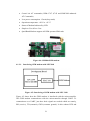
Figure 4.1: LPC2148 Development Board
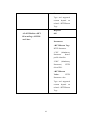
Features [6]
Includes LPC 2148 Header Board
No Separate power adapter required (USB power source)
Two RS-232 Interfaces (For direct connection to PC’s Serial port)
On Board Two Line LCD Display (2x16) (with jumper select option)
16
On Board USB Connector
On Board 1 Amp Voltage Regulator
On Board Connector for regulated 3V output
On Board Connector for regulated 5V output
Three On Board DB9 Connectors (Two for UART and One for CAN)
On Board Reset button
In this project, the serial port interface (COM0) has been used for GPS interface
and serial port interface (COM1) has been used for GSM interface. The 5 volt
output obtained from pin number 0 and 1 of the microcontroller has been used as a
power supply to the GPS receiver. The LCD display, available in the development
board, has been utilized as the Notice Board display to display the latitude and
longitude information.
4.1.2.
GPS
The GT-320R module has been used as the GPS receiver in this project. The GT320R is a compact all-in-one GPS module intended for a broad range of OEM
products, where fast and easy system integration and minimal development risk is
required. The module continuously tracks all satellites in view and provides
accurate satellite positioning data. Its 12 parallel channels and 4100 search bins
provide fast satellite signal acquisition and short startup time. Its low power
consumption is suitable for a wide range application in handhelds, sensors, asset
tracking, and vehicle navigation products. Both the LVTTL-level and RS232-level
serial interface are provided on the interface connector. Supply voltage of
3.8V~8.0V is supported [7].
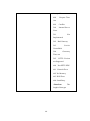
Features [7]
12 parallel channel GPS receiver
4100 simultaneous time-frequency search bins
SBAS (WAAS, EGNOS) support
-140dBm acquisition sensitivity
17
-150dBm tracking sensitivity
< 10 second hot start
< 50 second cold start
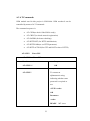
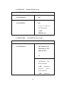
Table 4.1: Pin Out Function Description of GT-320R GPS module
Pin
Signal Name
Description
1
Serial Data Out (LVTTL)
Asynchronous serial output at LVTTL level
2
Serial Data In (LVTTL)
Asynchronous serial input at LVTTL level
3
Serial Data Out (RS-232)
Asynchronous serial output at RS-232 level
4
Serial Data In (RS-232)
Asynchronous serial input at RS-232 level
5
Power
3.8V~8.0V DC input
6
Ground
Power and signal ground
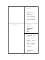
4.1.2.1. NMEA 0183
It refers to GPS data stream in ASCII format. The NMEA 0183 data stream
includes information on position, datum, water depth and other variables. The data
is sent in the form of sentence each starting with a $ sign and terminating with a
carriage return –line feed. The $ sign is followed by five characters address field
which identifies the talker, the data type and the string format of the successive
fields. The last field in any sentence is a check sum filed which follows a
checksum delimiter “*”. The maximum total number of characters in any sentence
is 82 [8].
An example $GPRMC response is shown below and the break-down of the
GPRMC sentence is presented in Table 4.2.
$GPRMC,123519,A,4807.038,N,01131.000,E,022.4,084.4,230394,003.1,W*6A
18
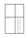
Table 4.2: RMC Data format
RMC
Recommended Minimum Sentence C
123519
Fix taken at 12:35:19
A
Status A=active or V=valid
4807.038,N
Latitude 48 07.038 N
01131.000,E
Longitude 11 31.000 E
022.4
Speed over ground in knots
084.4
Track angle in degrees true
230394
Date – 23rd March 1994
003.1,W
Magnetic Variation
*6A
Checksum data, always begins with *
4.1.2.2. Testing of GPS using Flash Magic Terminal
Figure 4.2: Data obtained from GPS module using Flash Magic Terminal
19
4.1.2.3. Interfacing GPS with LPC2148
Figure 4.3: Interfacing of GPS module with LPC 2148
Figure 4.3 shows how the GPS module has been interfaced with the
microcontroller. The GPS module continuously transmits serial data (RS-232
protocol) in the form of sentences according to NMEA standards. The latitude and
longitude values of the location are contained in the GPRMC sentence (refer
NMEA format). To communicate over UART, just three basic signals are needed
which are namely, RD (receive), TD (transmit), GND (common ground).
4.1.3.
GSM
The GSM modem used in this project is SIM 900A GSM modem. It works on
frequencies
EGSM
900MHz/DCS
1800MHZ
and
GSM
850MHz/PCS
1900MHz.The module is fitted with standard interface for a power supply, an
antenna, a pc and a headset with its plug and play technology. It uses SIM Card
and can be controlled by means of AT Commands.
Features [4]
Quad-Band 850/ 900/ 1800/ 1900 MHz
Dual-Band 900/ 1900 MHz
GPRS multi-slot class 10/8 GPRS mobile station class B
Compliant to GSM phase 2/2+Class 4 (2 W @850/ 900 MHz)
Class 1 (1 W @ 1800/1900MHz)
20
Control via AT commands (GSM 07.07 ,07.05 and SIMCOM enhanced
AT Commands)
Low power consumption: 1.5mA(sleep mode)
Operation temperature: -40°C to +85 °C
Status of Modem Indicated by LED
Simple to Use & Low Cost
Quad Band Modem supports all GSM operator SIM cards
Figure 4.4: SIM900 GSM modem
4.1.3.1. Interfacing GSM modem with LPC2148
Figure 4.5: Interfacing of GSM modem with LPC 2148
Figure 4.5 shows how the GSM modem is interfaced with the microcontroller.
The GSM modem communicates with the microcontroller through UART. To
communicate over UART, just three basic signals are needed which are namely,
RD (receive), TD (transmit), GND (common ground). In this scheme RTS and
21
CTS signals of serial port interface of GSM modem are connected with each
other. The transmit signal of serial port of microcontroller is connected with
transmit signal (TD) of the serial interface of GSM Modem while receive signal of
microcontroller serial port is connected with receive signal (RD) of serial interface
of GSM Modem. The GSM modem is used in the data acquisition section of
the project for transmitting the received GPS data to the Tracking Server via
GPRS connection. The modem is given the appropriate AT commands by the
microcontroller to which it is interfaced through the serial port. Software flow
control mechanism is employed for transferring the data between the
microcontroller and a modem.
4.1.4. UART
Universal Asynchronous Receiver/Transmitter, abbreviated UART is a piece of
computer hardware that translates data between parallel and serial forms. A
UART is usually an individual (or part of an) integrated circuit used for serial
communications over a computer or peripheral device serial port. UARTs are now
commonly included in microcontrollers. A DUART combines two UARTs into a
single chip. Many modern ICs now come with a UART that can also communicate
synchronously; these devices are called USARTs. The UART takes bytes of data
and transmit the individual bits in a sequential fashion. At the destination, a
second UART re-assembles the bits into complete bytes. Each UART contains a
shift register, which is the fundamental method of conversion between serial and
parallel forms. Serial transmission of digital information (bits) through a single
wire or other medium is less costly than parallel transmission through multiple
wires. The UART usually does not directly generate or receive the external signals
used between different items of equipment. Separate interface devices are used to
convert the logic level signals of the UART to and from the external signaling
levels. External signals may be of many different forms. Examples of standards
for voltage signaling are RS-232, RS-422 and RS-485 from the EIA [9].
22
4.1.5. Liquid Crystal Display
LCD is an electronic visual display device. It uses light modulating properties of
liquid crystals. It has been used to display current position (latitude, longitude,
time and speed). The LCD screen is used in this project because of its ability to
display numbers, characters, and graphics as well as because of its low price and
easy availability in the market. LCD incorporates a refreshing controller. Based on
the command, it can be operated in either four bit mode or in eight bit mode.
4.2. Software Implementation for Web
4.2.1. ASP.NET MVC
The ASP.NET MVC is an open source web application framework that
implements the model–view–controller (MVC) pattern. Based on ASP.NET,
ASP.NET MVC allows software developers to build a web application as a
composition of three roles: Model, View and Controller. The MVC model defines
web applications with 3 logic layers:
Model (business layer)
View (display layer)
Controller (input control)
A model represents the state of a particular aspect of the application. A controller
handles interactions and updates the model to reflect a change in state of the
application, and then passes information to the view. A view accepts necessary
information from the controller and renders a user interface to display that
information [10].
23
Features [10]
Compatible Language: C#, VB.net
Operating System: Cross Platform
Platform: Net Framework, Mono
Type: Web Application framework
License: Apache License 2.0
In the server side of this project, enriched classes of ASP.NET MVC were used
for function such as parsing NMEA string of GPS, sent by the hardware device,
into location, latitude, date, time and velocity and tracking changes in the
Tracking Server.
4.2.2. ASP.NET Web 2.0
ASP.NET Web 2.0 API is a framework that makes it easy to build HTTP services
that reach a broad range of clients, including browsers and mobile devices.
ASP.NET Web API is an ideal platform for building REST full applications on
the .NET Framework. A Web 2.0 site may allow users to interact and collaborate
with each other in a social media dialogue as creators of user-generated content in
a virtual community, in contrast to Web sites where people are limited to the
passive viewing of content. Examples of Web 2.0 are blogs, wikis, folksonomies,
video sharing sites, hosted services, Web applications, and mashups.
4.2.3. Microsoft Azure
Microsoft Azure is a cloud computing platform and infrastructure, created by
Microsoft, for building, deploying and managing applications and services
through a global network of Microsoft-managed data centers [11].
Features [11]
Websites that allows developers to build sites using ASP.NET, PHP,
Node.js, or Python and can be deployed using FTP, Git, Mercurial or
Team Foundation Server.
24
Virtual
machines
that
let
developers
migrate
applications
and
infrastructure without changing existing code, and can run both Windows
Server and Linux virtual machines.
Cloud services - Microsoft's Platform as a Service (PaaS) environment that
is used to create scalable applications and services. Supports multi-tier
scenarios and automated deployments.
Data management - SQL Database, formerly known as SQL Azure
Database, works to create, scale and extend applications into the cloud
using Microsoft SQL Server technology. Integrates with Active Directory
and Microsoft System Center and Hadoop.
Media services - A PaaS offering that can be used for encoding, content
protection, streaming, and/or analytics.
4.2.4. Visual Studio 2013
Visual Studio 2013 is a developer tool that allows developers to create
applications for Windows 8.1, Windows Phone, the web or the cloud as well as
standards-based, responsive websites, web APIs, or real-time online experiences
using ASP.NET. It helps in publishing web application directly to Windows
Azure from the IDE as well as to create web services consumed by connected
devices.
4.2.5. Web Hosting Service Provider (000webhost.com)
000webhost.com ($0.00 webhost), is an industry leader in providing top class free
web hosting services. Every account receives 1500MB space and a whopping
100G bandwidth free of cost. This was the main point of attraction about this web
hosting service. As this project is not yet commercially launched, occasional
server overload can be tolerated and so this free web hosting service was used. It
also supports various software/services like My SQL, PHP MyAdmin, Website
Builder, File Manager, Free Domain Name etc.
25
4.2.6. Domain Name (.net76.net)
The webhost also provides free domain name as “.net76.net”. The registered
domain name, in 000webhost.com, web hosting service, for this project’s website
is www.intelligenttranspotationsystem.net76.net.
4.2.7. HTML
Hyper Text Markup Language (HTML) is the main markup language for
displaying web pages and other information that can be displayed in a web
browser. HTML is written in the form of HTML elements consisting of tags
enclosed in angle brackets (like <html>), within the web page content. HTML
tags most commonly come in pairs like <h1> and </h1>, although some tags,
known as empty elements, are unpaired, for example <img>. The first tag in a pair
is the start tag, the second tag is the end tag (they are also called opening tags and
closing tags). In between these tags web designers can add text, tags, comments
and other types of text-based content [12].
4.2.8. JavaScript
JavaScript is a programming language used to make web pages interactive. It runs
on visitor's computer and doesn't require constant downloads from website. It is
programming code that can be inserted into HTML pages to be executed by web
browser. Most of the APIs’ that we have used are scripted in JavaScript [12].
4.2.9. CSS
Cascading Style Sheets (CSS) is a style sheet language used for describing the
look and formatting of a document written in a markup language. While most
often used to style web pages and user interfaces written in HTML and XHTML,
the language can be applied to any kind of XML document, including plain XML,
SVG and XUL.
In this project, CSS have been used for formatting our client side webpage [13].
26
4.2.10. Adobe Dreamweaver CS6
Adobe Dreamweaver is a web development tool, developed by Adobe Systems,
that provides Design view and a code editor with standard features such as syntax
highlighting, code completion, and code collapsing as well as more sophisticated
features such as real-time syntax checking and code introspection for generating
code hints to assist the user in writing code. Dreamweaver features an integrated
browser for previewing developed WebPages in the program's own preview pane
in addition to allowing content to be open in locally installed web browsers.
Dreamweaver can use third-party "Extensions" to extend core functionality of the
application, which web developers can write (largely in HTML and JavaScript).
Dreamweaver, like other HTML editors, edits files locally then uploads them to
the remote web server using FTP, SFTP, or WebDAV. It supports different
language like: Active Server Pages (ASP), C#, Cascading Style Sheets (CSS),
HyperText Markup Language (HTML), Java, JavaScript, PHP: Hypertext
Preprocessor (PHP), etc. This software was used for developing client side
webpage using html, java script and CSS [14].
4.3. Software for Android Application development
4.3.1. Eclipse ADT
ADT (Android Development Tools) is a plug-in for Eclipse that provides a suite
of tools that are integrated with the Eclipse IDE. It offers access to many features
that help you develop Android applications quickly. ADT provides GUI access to
many of the command line SDK tools as well as a UI design tool for rapid
prototyping, designing, and building of application's user interface. Because ADT
is a plug-in for Eclipse, the functionality of a well-established IDE, along with
Android-specific features that are bundled with ADT is available.
The following describes important features of Eclipse and ADT [15]:
Integrated Android project creation, building, packaging, installation,
and debugging: ADT integrates many development workflow tasks into
27
Eclipse, making it easy for you to rapidly develop and test your Android
applications.
SDK Tools integration: Many of the SDK tools are integrated into
Eclipse's menus, perspectives, or as a part of background processes ran by
ADT.
Java programming language and XML editors: The Java programming
language editor contains common IDE features such as compile time
syntax checking, auto-completion, and integrated documentation for the
Android framework APIs. ADT also provides custom XML editors that let
you edit Android-specific XML files in a form-based UI. A graphical
layout editor lets you design user interfaces with a drag and drop interface.
Integrated documentation for android framework APIs: You can
access documentation by hovering over classes, methods, or variables.
4.3.2. XML
Extensible Markup Language (XML) is a markup language that defines a set of
rules for encoding documents in a format that is both human-readable and
machine-readable. It is defined in the XML 1.0 Specification produced by the
W3C, and several other related specifications, all free standards. The design goals
of XML emphasize simplicity, generality, and usability over the Internet It is a
textual data format with strong support via Unicode for different human
languages. Although the design of XML focuses on documents, it is widely used
for the representation of arbitrary data structures, for example in services. Many
application programming interfaces (APIs) have been developed to aid software
developers with processing XML data, and several schema systems exist to aid in
the definition of XML-based languages.
4.3.3. JSON
JavaScript Object Notation is an open standard format that uses human-readable
text to transmit data objects consisting of attribute–value pairs. It is used primarily
to transmit data between a server and web application, as an alternative to XML.
28
Although originally derived from the JavaScript scripting language, JSON is a
language-independent data format, and code for parsing and generating JSON data
is readily available in a large variety of languages. The JSON format was
originally specified by Douglas Crock ford. It is currently described by two
competing standards, RFC 7159 and ECMA-404. The ECMA standard is
minimal, describing only the allowed grammar syntax, whereas the RFC also
provides some semantic and security considerations. The official Internet media
type for JSON is application/JSON. The file extension name for JSON is .json.
29
5. TIME SCHEDULE AND COST
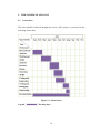
5.1. Gantt chart
The time schedule followed through the course of this project is presented in the
following Gantt chart.
Figure 5.1: Gantt Chart
Legend
: Working days
30
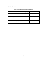
5.2. Cost Description
Table 5.1: Cost Description Table of the Project
Items
Quantity
Amount (Rs)
eCee LPC 2148 Development Board
1
12,000
GPS module
1
3,500
GSM modem
1
5,500
DB9 connectors
4
60
Serial to USB converter
1
600
Battery
1
100
Grand Total
21,760
31
6. RESULT
The principle objective of the project “Intelligent Transportation System” was to
develop an efficient and accurate vehicle tracking system for use in public
transportation. In addition to this, the project objective also included a means to
inform the general public about location of vehicles through a notice board system
at every bus station and via web and android applications.
To build the vehicle tracking system, an embedded system was built consisting of
a GPS module and a GSM modem interfaced with an LPC2148 development
board. This system is designed to be mounted on to every public vehicle currently
in operation within the public transportation system. The interface between all the
modules used in this tracking system meets the desired operation requirements
and the overall system has been tested successfully. The LPC2148 microcontroller
reads the GPRMC location data from the GPS module. The microcontroller also
communicates with the GSM modem via AT commands and initializes and sets up
GPRS connection and HTTP transmission protocol. The microcontroller
communicates the location data to the central data server thorough the GPRS
connection.
The central database server holds the database that stores the location information
of all the vehicles in the public transportation system. The central database of the
system is built on Microsoft Azure cloud storage. The database server receives the
full length GPS data in raw GPRMC format and parses the raw GPRMC string to
extract location, date and time information. This stored data is available for
download and is used to display location information to the end user.
The end user can access the location data of a vehicle by three means – namely
notice board display at bus station, web application and android application.
The notice board display unit is used to display the location data of vehicles to the
commuters at the bus stations. The notice board display unit consists of an
LPC2148 development board, a GSM modem. The LPC2148 microcontroller
communicates with the central database server through a GPRS connection
32
established using the GSM modem. The microcontroller then prints out the
location information on the LCD display present on the development board.
The web application is hosted on a free web hosting domain. The project website
is intelligenttransportation.net76.net/final/index2.php. The end user can view a
Google map plot of the current position of the vehicle by visiting this web page.
The android application also allows the end user to view the location information
as a plot on Google map. The application connects to the database sever and
extracts the most recent latitude and longitude data. This data, after proper
parsing, is plotted in Google maps thus allowing the user to track the desired
vehicle.
The objectives set for the project were thus met by the designed system. The final
prototype of the system is functional and with some optimization can be
developed into a commercially viable product.
33
7. APPLICATION
This project “Intelligent Transportation System” finds applications in a number of
ways:
Accurate Vehicle Tracking: This system involves accurate vehicle
tracking. It is used to locate the location of desired vehicles or any objects
which location we need to trace.
Transportation Management: Since passengers can get pre-informed of
the location of the buses they need to know, it saves considerable amount
of time. The queues and crowds in public vehicles and public stations will
be minimized.
Security Purpose: The system can be implemented to keep any objects
secure against theft. So that it can be used in private vehicle tracking.
Implementation with Sajha Yatayat: The system design can be applied
to Sajha Yatayat within the Kathmandu valley. This will help make Sajha
Yatayat more popular among the general public and it will be more
efficient.
34
8. PROBLEMS FACED
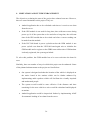
A number of problems were faced during the project.
The GPS module returned garbage data in initial days as no data was
obtained owing to cold start which was solved later on.
Connecting to the Server through GPRS required several attempts due to
the different errors in the network.
AT first the online database for the tracking server was created inside
000.webhost.com which is also the web hosting service of the project
website, but due to constant error while accessing the database, the
database’s location had to be changed to Microsoft Azure Cloud Storage.
35
9. LIMITATIONS AND FUTURE ENHANCEMENT
The objectives set during the start of the project have almost been met. However,
there are some limitations to this project. They are:
Android application has to be refreshed each time as it receives new data
from the server.
If the GPS module is not used for long time, then cold start occurs during
power up. So if the system has to be used after a long time, the cold start
time of the GPS module has to be waited out before a correct reading can
be made from the module.
If the LPC2148 board is power cycled/reset but the GSM module is not
power cycled/ reset then the LPC2148 board again tries to initialize the
GSM module and re-register to the GPRS network but since GSM modem
is already registered, the system gets halted.
To solve this problem, the GSM module has to be reset each time the board is
reset.
Similarly, there are number of ways in which this project can be enhanced. Some
of the planned enhancements to the project are listed below:
Our system is designed such that the location of the vehicle is displayed on
the notice board in the stations which can be further enhanced by
implementing audio speakers which will facilitate the visually impaired
and uneducated people.
The system overall would be more effective if the distance and time
remaining for the next vehicle to arrive could be calculated and displayed
at stations.
Android application could be improvised further by implementing AJAX
for automatic loading of new data from the server.
36
10. CONCLUSION
A sufficiently accurate vehicle tracking system was successfully designed and
implemented by the end of this project. The In-Vehicle Unit designed for the
project, effectively communicates location information to the central Tracking
Server and the data from the server is promptly made available to the end user via
Notice Board display, web application and android application.
This project was very helpful in developing skills demanded by technical design
and prototyping work. It helped in building efficient coding skills, debugging and
testing skills as well as helped in learning many important aspects of critical
problem analysis and troubleshooting. Designing and maintaining the server side
database also helped in learning efficient techniques of database management as
well as networking.
Apart from technical skills, the project was also helpful in learning the importance
of team work. This project was carried out under constraints of time and budget,
and helped in learning how to use effective time management and efficient budget
allocation techniques to carry out productive work under such constraints. Thus,
this project has proven to be a great learning experience and has served as good
preparation for working in other such highly technical projects.
37
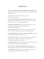
REFERENCES
[1] Gaire, Anil, Chalise, Basanta, Basnet, Binod and Sharma, Subhash. GPS
GSM Integration for Enhancing Public Transportation System. Lalitpur : Institute
of Engineering, 2013.
[2] Winnipeg Transit. [Online] [Cited: February 12, 2014.]
http://winnipegtransit.com/en.
[3] Guo, Xiaoya, Huang, Emily, Huang, Benson and Juras, Lara. Design a
Smart Bus System. British Columbia : University of Victoria, 2012. Available
Online: http://www.ece.uvic.ca/~bhung/399/index.html.
[4] Electronics Technology Team. ETTeam. [Online] [Cited: June 6, 2014.]
www.etteam.com/prod2013/et-base%20gsm%20sim900/ETBASE%20GSM%20SIM900.pdf.
[5] NXP Semiconductors. UM10139 LPC214x User manual. [Online] [Cited:
May 14, 2014.] www.nxp.com/documents/user_manual/UM10139.pdf.
[6] Poudel, Bikash, Kansakar, Prasanna and Chhetri, Sujit Rokka. A Training
Manual on FPGA and ARM. Kathmandu, 2013. Vol. 1.
[7] UniTraQ. GT-320R Datasheet. UniTraQ International Corp. [Online] 2014.
[Cited: April 12, 2014.] http://www.unitraq.com/a/file/product/GT320%20Data%20Sheet%20V1.0-20120828.pdf.
[8] Boondog Automation. GPS Serial Communications. [Online] [Cited: June 24,
2014.] http://www.boondog.com/tutorials/gps/gps.html.
[9] Sloss, Andrew N., Symes, Dominic and Wright, Chris. ARM System
Developer's Guide. Second Edition. San Francisco : Morgan Kaufmann, 2005.
[10] Wikipedia. ASP.NET MVC Framework. [Online] [Cited: August 1, 2014.]
http://en.wikipedia.org/wiki/ASP.NET_MVC_Framework.
38
[11] Wikipedia. Microsoft Azure. [Online] [Cited: August 1, 2014.]
http://en.wikipedia.org/wiki/Microsoft_Azure.
[12] W3Schools. W3Schools Online Web Tutorials. [Online] [Cited: July 14,
2014.] http://www.w3schools.com/.
[13] Wikipedia. Cascading Style Sheets. [Online] [Cited: August 1, 2014.]
http://en.wikipedia.org/wiki/Cascading_Style_Sheets.
[14] Wikipedia. Adobe Dreamweaver. [Online] [Cited: August 1, 2014.]
http://en.wikipedia.org/wiki/Adobe_Dreamweaver.
[15] Google Developers. Android Application Development. [Online] [Cited:
July 20, 2014.] http://developer.android.com/training/index.html.
39
APPENDIX
A.1 Web Application
Web application layout was designed using HTML & CSS.
Major command includes following:
tags
description
<div>
Refers to a division or a section in an
HTML document. It is used to group
block-elements to format them with CSS.
<a href=””></a>
Defines a hyperlink, used to link from one
page to another. In the case of our project,
we have used sajha.html as link's
destination.
Functionality was added to application using Javascript.
Google API’s:
Google Hosted Libraries that serves jQuery to your users directly from Google’s
network of datacenters ( 1.5.1 & 1.8.11 are stable versions).
Insert
your
generated
API
key
in
the
required key parameter
(key=YOUR_API_KEY).
The sensor parameter is required and it indicates whether this application uses a
sensor (such as a GPS locator) to determine the user's location. Set this value to
either true or false.
(i)"http://ajax.googleapis.com/ajax/libs/jquery/1.5.1/jquery.min.js"
(ii)"http://ajax.googleapis.com/ajax/libs/jqueryui/1.8.11/jquery-ui.min.js"
(iii)https://maps.googleapis.com/maps/api/js?key=AIzaSyC6oXZijZTNoggBZxPc
daW6HjY1V7SzQHI&sensor=false
40
Define Properties for Map
To initialize a Map, we first create a Map properties object to define some
properties for the map:
var mapProp = {
center:new google.maps.LatLng(51.508742,-0.120850),
zoom:7,
mapTypeId: google.maps.MapTypeId.ROADMAP
};
Center
The center property specifies where to center the map. Create a LatLng object to
center the map on a specific point. Pass the coordinates in the order: latitude,
longitude.
Zoom
The zoom property specifies the initial zoom level for the map. zoom: 0 shows a
map of the Earth fully zoomed out. Higher zoom levels zoom in at a higher
resolution.
MapTypeId
The mapTypeId property specifies the initial map type to display.
The following map types are supported:
ROADMAP (normal, default 2D map)
SATELLITE (photographic map)
HYBRID (photographic map + roads and city names)
TERRAIN (map with mountains, rivers, etc.)
Where to Show the Google Map
A named <div> element is often used to hold/show the Google Map:
<div id="googleMap" style="width:500px;height:380px;"></div>
41
Create a Map Object
var map=new google.maps.Map(document.getElementById("googleMap")
,mapProp);
The code above creates a new map inside the <div> element (googleMap) using
the parameters that are passed (mapProp).
Add Marker
The Marker constructor creates a marker. (Note that the position property must be
set for the marker to display).
Add the marker to the map by using the setMap() method:
var marker=new google.maps.Marker({
position:myCenter,
icon:'pinkball.png' //marker with image icon
});
marker.setMap(map);
Loading the Map
Execute the initialize() function that constructs the Map object on window load, to
ensure that the map is placed on the page after the page is fully loaded:
google.maps.event.addDomListener(window, 'load', initialize);
The getCurrentPosition() Method - Return Data
Use the getCurrentPosition() method to get the user's position.
<script>
var x = document.getElementById("demo");
function getLocation() {
if (navigator.geolocation) {
navigator.geolocation.getCurrentPosition(showPosition);
} else {
x.innerHTML = "Geolocation is not supported by this browser.";
}
42
}
function showPosition(position) {
x.innerHTML = "Latitude: " + position.coords.latitude +
"<br>Longitude: " + position.coords.longitude;
}
</script>
Example explaination:
Check if Geolocation is supported
If supported, run the getCurrentPosition() method. If not, display a
message to the user
If the getCurrentPosition() method is successful, it returns a coordinates
object to the function specified in the parameter ( showPosition )
The showPosition() function gets the displays the Latitude and Longitude
Ajax function:
AJAX is the art of exchanging data with a server, and updating parts of a web
page - without reloading the whole page.
Example:
Jquery.ajax({
Type:Get/Post, // the type of request: GET or POST
url:”http:url”, // the location of the file on the server
async:true/false, // true (asynchronous) or false (synchronous)
success:function(data){//do something if url loading sucess}
}
Error: function(err){//else do something
43
A.2 Android Application
Programming for Android Application Development can be classified into the
following files
Java implementation file - This is the file that implements the behavior
of the widget. If you can instantiate the object from layout XML, you
will also have to code a constructor that retrieves all the attribute values
from the layout XML file.
XML definition file - An XML file in res/values/ that defines the XML
element used to instantiate your widget, and the attributes that it
supports. Other applications will use this element and attributes in their
in another in their layout XML
Java implementation file is composed of different classes
MainActivity Class
The Activity class is an important part of an application's overall lifecycle,
and the way activities are launched and put together is a fundamental part
of the platform's application model
Activity Lifecycle
Activities in the system are managed as an activity stack. When a new
activity is started, it is placed on the top of the stack and becomes the
running activity -- the previous activity always remains below it in the
stack, and will not come to the foreground again until the new activity
exits.
An activity has essentially four states:
If an activity in the foreground of the screen (at the top of the stack), it is
active or running.
If an activity has lost focus but is still visible (that is, a new non-full-sized
or transparent activity has focus on top of your activity), it is paused. A
44
paused activity is completely alive (it maintains all state and member
information and remains attached to the window manager), but can be
killed by the system in extreme low memory situations.
If an activity is completely obscured by another activity, it is stopped. It
still retains all state and member information, however, it is no longer
visible to the user so its window is hidden and it will often be killed by the
system when memory is needed elsewhere.
If an activity is paused or stopped, the system can drop the activity from
memory by either asking it to finish, or simply killing its process. When it
is displayed again to the user, it must be completely restarted and restored
to its previous state.
The following diagram shows the important state paths of an Activity. The
square rectangles represent callback methods you can implement to
perform operations when the Activity moves between states. The colored
ovals are major states the Activity can be in.
45
There are three key loops you may be interested in monitoring within your
activity:
The entire lifetime of an activity happens between the first call
toonCreate(Bundle) through to a single final call toonDestroy(). An activity will
do all setup of "global" state in onCreate(), and release all remaining resources
in onDestroy(). For example, if it has a thread running in the background to
46
download data from the network, it may create that thread in onCreate() and
then stop the thread in onDestroy().
The visible lifetime of an activity happens between a call toonStart() until a
corresponding call to onStop(). During this time the user can see the activity onscreen, though it may not be in the foreground and interacting with the user.
Between these two methods you can maintain resources that are needed to show
the activity to the user. For example, you can register a Broadcast Receiver in
onStart() to monitor for changes that impact your UI, and unregister it in
onStop() when the user no longer sees what you are displaying. The onStart()
and onStop() methods can be called multiple times, as the activity becomes
visible and hidden to the user.
The foreground lifetime of an activity happens between a call to
onResume()until a corresponding call to onPause(). During this time the
activity is in front of all other activities and interacting with the user. An
activity can frequently go between the resumed and paused states -- for example
when the device goes to sleep, when an activity result is delivered, when a new
intent is delivered -- so the code in these methods should be fairly lightweight.
The entire lifecycle of an activity is defined by the following Activity methods.
All of these are hooks that you can override to do appropriate work when the
activity changes state. All activities will implement onCreate(Bundle)to do their
initial setup; many will also implement onPause()to commit changes to data and
otherwise prepare to stop interacting with the user. You should always call up to
your super class when implementing these methods.
public class Activity extends ApplicationContext {
protected void onCreate(Bundle savedInstanceState);
protected void onStart();
protected void onRestart();
protected void onResume();
protected void onPause();
47
protected void onStop()
protected void onDestroy();
}
Map
A Map is a data structure consisting of a set of keys and values in which each
key is mapped to a single value. The class of the objects used as keys is
declared when the Map is declared, as is the class of the corresponding values.
A Map provides helper methods to iterate through all of the keys contained in
it, as well as various methods to access and update the key/value pairs.
HashMap is an implementation of Map. All optional operations are supported.
All elements are permitted as keys or values, including null.
Intent
Intent provides a facility for performing late runtime binding between the code
in different applications. Its most significant use is in the launching of
activities, where it can be thought of as the glue between activities. It is
basically a passive data structure holding an abstract description of an action
to be performed.
AsyncTask
AsyncTask enables proper and easy use of the UI thread. This class allows
performing background operations and publishing results on the UI thread
without having to manipulate threads and/or handlers.
AsyncTask is designed to be a helper class around Thread and Handler and
does not constitute a generic threading framework. AsyncTasks should ideally
be used for short operations (a few seconds at the most.) If you need to keep
threads running for long periods of time, it is highly recommended you use the
various APIs provided by the java.util.concurrentpacakge such as Executor,
ThreadPoolExecutor and FutureTask.
48
An asynchronous task is defined by a computation that runs on a background
thread and whose result is published on the UI thread. An asynchronous task is
defined by 3 generic types, called Params, Progress and Result, and 4 steps, called
onPreExecute, doInBackground, onProgressUpdate
and onPostExecute.
The 4 steps
When an asynchronous task is executed, the task goes through 4 steps:
onPreExecute(), invoked on the UI thread before the task is executed. This
step is normally used to setup the task, for instance by showing a progress
bar in the user interface.
doInBackground(Params...),
invoked
on
the
background
thread
immediately after onPreExecute() finishes executing. This step is used to
perform background computation that can take a long time. The
parameters of the asynchronous task are passed to this step. The result of
the computation must be returned by this step and will be passed back to
the last step. This step can also use publishProgress(Progress...) to publish
one or more units of progress. These values are published on the UI thread,
in the onProgressUpdate(Progress...)step.
onProgressUpdate(Progress...), invoked on the UI thread after a call to
publishProgress(Progress...). The timing of the execution is undefined.
This method is used to display any form of progress in the user interface
while the background computation is still executing. For instance, it can be
used to animate a progress bar or show logs in a text field.
onPostExecute(Result), invoked on the UI thread after the background
computation finishes. The result of the background computation is passed
to this step as a parameter.
JSONArray
JSONArray
has the same type coercion behavior and optional/mandatory accessors
as JSONObject. See that class' documentation for details.
49
InputStream
Most clients will use input streams that read data from the file system
(FileInputStream), the network (getInputStream()/getInputStream()), or from an
in-memory byte array (ByteArrayInputStream).
Use InputStreamReader to adapt a byte stream like this one into a character
stream.
Most clients should wrap their input stream with BufferedInputStream. Callers
that do only bulk reads may omit buffering.
Some implementations support marking a position in the input stream and
resetting back to this position later. Implementations that don't return false from
markSupported() and throw an IOException when reset() is called.
HTTPClientClass Overview
Interface for an HTTP client. HTTP clients encapsulate a smorgasbord of objects
required to execute HTTP requests while handling cookies, authentication,
connection management, and other features. Thread safety of HTTP clients
depends on the implementation and configuration of the specific client.
Buffered Reader Class Overview
Wraps an existing Reader and buffers the input. Expensive interaction with the
underlying reader is minimized, since most (smaller) requests can be satisfied by
accessing the buffer alone. The drawback is that some extra space is required to
hold the buffer and that copying takes place when filling that buffer, but this is
usually outweighed by the performance benefits.
A typical application pattern for the class looks like this:
BufferedReaderbuf = new BufferedReader(new FileReader("file.java"));
Connectivity Manager
The primary responsibilities of this class are to:
50
1. Monitor network connections (Wi-Fi, GPRS, UMTS, etc.)
2. Send broadcast intents when network connectivity changes
3. Attempt to "fail over" to another network when connectivity to a network is lost
4. Provide an API that allows applications to query the coarse-grained or finegrained state of the available networks
Network Info
Use getActiveNetworkInfo() to get an instance that represents the current network
connection.
JSONObject
This class can coerce values to another type when requested.
When the requested type is a boolean, strings will be coerced using a caseinsensitive comparison to "true" and "false".
When the requested type is a double, other Number types will be coerced using
doubleValue. Strings that can be coerced using valueOf(String) will be.
When the requested type is an int, other Number types will be coerced using
intValue. Strings that can be coerced using valueOf(String) will be, and then
cast to int.
When the requested type is a long, other Number types will be coerced using
longValue. Strings that can be coerced using valueOf(String) will be, and then
cast to long. This two-step conversion is lossy for very large values. For
example,
the
string
"9223372036854775806"
yields
the
long
9223372036854775807.
When the requested type is a String, other non-null values will be coerced using
valueOf(Object). Although null cannot be coerced, the sentinel value NULL is
coerced to the string "null".
51
For User Interface Designing we used XML format.
Widgets like ImageView, TextView, Button and EditText were used in Linear
Layout.
ImageView
Displays a button with an image (instead of text) that can be pressed or clicked by
the user and displays an arbitrary image, such as an icon. The ImageView class
can load images from various sources (such as resources or content providers),
takes care of computing its measurement from the image so that it can be used in
any layout manager, and provides various display options such as scaling and
tinting.
TextView
Displays text to the user and optionally allows them to edit it. A TextView is a
complete text editor, however the basic class is configured to not allow editing.
Button
A button with two states, checked and unchecked. Represents a push-button
widget. Push-buttons can be pressed, or clicked, by the user to perform an action.
Interface definition for a callback to be invoked when a button is clicked.
EditText
An editable text view that shows completion suggestions automatically while the
user is typing. EditText is a thin veneer over TextView that configures itself to be
editable.
52
A.3 AT Commands
GSM module used in this project is SIM 900A GSM modem.It can be
controlled by means of AT Commands.
The command sequence is:
AT+CPIN(to check if the SIM is ready)
AT+CREG?(to check network registration)
AT+SAPBR (for bearer checking)
AT+HTTPINIT (for HTTP initialization).
AT+HTTPPARA(to set HTTP parameter)
AT+HTTPACTION(for GET and POST action of HTTP)
AT+CPIN
Enter PIN
AT+CPIN
Enter PIN
Test Command
Response
AT+CPIN=?
OK
Read Command
Response
AT+CPIN?
TA returns an
alphanumeric string
indicating whether some
password is required or
not.
+CPIN:<code>
OK
Parameter
<code>
READY
53
MT is not
pending any password.
SIMPIN
MT is waiting
SIM PIN to be given.
SIMPUK MT is waiting
SIM PIN to be given.
AT+CREG
Network Registration
AT+CREG
Network Registration
Test Command
Response
AT+CREG=?
+CREG : (list of
supported <n>s)
OK
Parameter
<n>
0 Disable network
registration
unsolicitated result
code
1 Enable network
registration
unsolicitated result
code +CREG:<stat>
2
Enable network
registration
unsolicitated result
code with location
information
+CREG:<stat>[,<lac
54
>,<cid>]
Read Command
Response
AT+CREG?
TA returns the ststus
of result code
presesntstion and an
integer <stat> which
shows whether the
network has currently
indicated the
registration of the
ME. Location
information elements
<lac>and <ci> are
returned only when
<n>=2 and ME is
registered in the
network.
+CREG:<n>,<stat>[
55
,<lac>,<ci>]
OK
If error is related ME
functionality:
+CME
ERROR:<err>
AT+SAPBR Bearer Setting for Application Based on IP
AT+SAPBR Bearer Setting for Application Based on IP
Test Command
Response
AT+SAPBR=?
+SAPBR: (0-5),(13),”ConParmTag”,”
ConParamValue”
OK
Parameters
<ConParam
Tag>
bearer parameter
“CONTYPE” Type
of internet connection
Value
refer
to
<ConP”aram
Value_ConType>
“APN”
Access
point
string:maximum
characters
56
name
50
Write Command
Response
AT+SAPBR+<CMD_T
YPE>,<CID>,[<ConPar
OK
am
If<cmd_type>=2
Tag>,<ConParamValue
+SAPBR:<cid>,<sta
>]
tus>,<IP_Addr>
OK
If <cmd_type=4
+SAPBR:
<ConParam
Tag>,<ConParam
Value>
OK
Parameter
<cmd_type>
0 close bearer
1 open bearer
2 query bearer
3
set
bearer
parameters
4
get
bearer
parameters
<cid> bearer profile
57
identifier
<status>
0 bearer is connecting
1 bearer is connected
2 bearer is closing
3 Bearer is closed
<ConparamValue>b
earer parameter value
<ConParamValue_
ConType>
“CSD”
Circuit-
switched data call
“GPRS”
GPRS
connection
<ConParamValue_
Rate>
0
2400
1
4800
2
9600
3
14400
<IP_Addr> the IP
address of bearer
58
AT+HTTPINIT
Initialize HTTP Service
AT+HTTPINIT
Initialize HTTP Service
Test Command
Response
AT+HTTPINIT=?
OK
Execution Command
Response
AT+HTTPINIT
OK
If error is related to
ME functionality
+CME
ERROR:<err>
AT+HTTPPARA
Set HTTP Parameter Value
AT+HTTPPARA
Set HTTP Parameter Value
Test Command
Response
AT+HTTPARA=?
+HTTPPARA:”HT
TPParamTag”,”HT
TPParmValue”
OK
Parameters
<HTTPParam
Tag>
HTTP Parameter
“CID”
Parameter
(Mandatory
)bearer
profile identifier
“URL”
59
(Mandatory
Parameter)
HTTP
client URL .
<HTTPParam
Value>
HTTP
Parameter value
Type and supported
content
depend
on
related <HTTPParam
Tag>
Read Command
Resonse
AT+HTTPPARA?
+HTTPPARA:
<HTTPParamTag>,
<HTTPParam
Value>
OK
Parameters
<HTTPParam
Tag>
HTTP Parameter
“CID”
(Mandatory
Parameter
)bearer
profile identifier
“URL”
(Mandatory
Parameter)
HTTP
client URL .
<HTTPParam
Value>
60
HTTP
Parameter value
Type and supported
content
depend
on
related <HTTPParam
Tag>
Write Command
Response
AT+HTTPARA=<HTT
OK
PParamTag>,<HTTPP
araValue>
Parameters
<HTTPParam Tag>
HTTP Parameter
“CID”
(Mandatory
Parameter
)bearer
profile identifier
“URL”
(Mandatory
Parameter)
HTTP
client URL .
<HTTPParam
Value>
HTTP
Parameter value
Type and supported
content
depend
on
related <HTTPParam
Tag>
61
AT+HTTPACTION
HTTP Method action
AT+HTTPACTION
HTTP Method action
Test Command
Response
AT+HTTPACTION=?
+HTTPACTION: (0-2)
OK
Write Command
Response
AT+HTTPACTION=<Method>
OK
If error is related to ME
functionality:
+CME ERROR:<err>
Unsolicited result code:
+HTTPACTION:<Met
hod>,<StatusCode>,<D
atalen>
Parameter
<Method>
method
HTTP
specification:
0
GET
1
POST
2
HEAD
<StatusCode> HTTP
status code responded
by remote server it
identifier
refer
HTTP1.1(RFC2626)
62
to
100
Continue
101
Switching
Protocols
200
OK
201
Created
202
Accepted
203
Not
Authoritative
Information
203
Not Content
204
Reset Content
205
Partial Content
300
Multiple
Choices
301
Moved
Permanently
302
Found
303
See Other
304
Not Modified
305
Use Proxy
307
Temporary
Redirect
400
Bad Request
401
Unauthorized
406
63
Not
Acceptable
408
Request Time
Out
409
Conflict
500
Internal Server
Error
501
Not
Implemented
502
Bad Gateway
503
Service
Unavailable
504
Gateeway
Time-out
505
HTTP Version
not Supported
600
Not HTTP PDU
601 Network Error
602 No Memory
603 DNS Error
604 Stack Busy
<DataLen>
length of data got
64
The