1
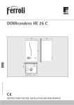
AquaSol
Unvented Solar Hot Water System
Installation & User Manual
THIS MANUAL IS TO BE LEFT WITH THE HOUSEHOLDER
AFTER INSTALLATION
Férroli Ltd.
Lichfield Road
Branston Industrial Estate
Burton-Upon-Trent
Staffordshire
United Kingdom
DE14 3HD
Tel 08707 282 885
Fax 08707 282 886
E-mail [email protected]
Contents
1.
2.
3.
4.
5.
6.
General instructions............................................................................................................ 3
Technical Specifications .................................................................................................... 4
System requirements .......................................................................................................... 4
Component Checklist ......................................................................................................... 4
Handling the Unit ............................................................................................................... 5
Positioning and Mounting the Unit .................................................................................... 5
6.1
Locating the Unit........................................................................................................ 5
6.2
Mounting Requirements............................................................................................. 6
6.3
Positioning and Mounting the System ....................................................................... 6
7. Installing the Unit............................................................................................................... 7
7.1
Before connecting this unit: ....................................................................................... 8
7.2
Assembling the Pump and filling manifold................................................................ 8
7.3
Assembling the unit.................................................................................................... 9
7.4
Ferroli AquaSol Solar Drain-back system ............................................................... 10
7.5
Cold water inlet kit and Boiler connections:............................................................ 11
7.6
To connect the unit:.................................................................................................. 12
7.7
High buildings -> optional drain-back tank ............................................................. 13
7.8
Electrical Connections: ............................................................................................ 14
7.9
Installing Discharge Pipes........................................................................................ 15
7.10 Advice on use in Hard Water Areas......................................................................... 17
7.11 Completing the Installer’s label ............................................................................... 17
8. Commissioning the System and User information........................................................... 18
8.1
Filling the Cylinder .................................................................................................. 18
8.2
Filling the Solar Circuit............................................................................................ 18
8.3
Starting the System................................................................................................... 19
8.4
System Failure.......................................................................................................... 19
9. Maintaining the System.................................................................................................... 19
9.1
Annual Maintenance ................................................................................................ 19
9.2
Draining the System ................................................................................................. 20
9.3
Flushing the System ................................................................................................. 20
10.
Differential Temperature Controller ............................................................................ 21
10.1 Fault finding errors................................................................................................... 21
10.2 Low priority codes ................................................................................................... 22
10.3 High priority codes................................................................................................... 23
11.
Service Log .................................................................................................................. 24
All rights reserved
Specifications and information contained in this manual are furnished for informational use only, and are subject to change at
any time without notice, and should not be construed as a commitment by Ferroli. Ferroli assumes no responsibility or liability for
any errors or inaccuracies that may appear in this manual, including the products and functions described in it.
Copyright © 2006
No part of this manual, including the products and functions described in it, may be reproduced, transmitted, transcribed, stored
in a retrieval system, or translated into any language in any form or by any means, except documentation kept by the purchaser
for backup purposes, without the express written permission of Ferroli ltd.
M 1261-06-X AquaSol Ferroli Installation Manual.doc
July 2006
Page 2 of 24
1. General instructions
This device must only be used for the purpose for which it is specially designed. This unit is
designed to heat water to a temperature below boiling point and must be connected to a
heating system and/or a water supply system for domestic use, compatible with its
performance, characteristics and its heating capacity. Any other use is considered improper.
AQUASOL INSTALLATION MUST ONLY BE PERFORMED BY QUALIFIED PERSONNEL, IN
ACCORDANCE WITH ALL THE INSTRUCTIONS GIVEN IN THIS TECHNICAL MANUAL, THE
PROVISIONS OF CURRENT LAW, THE RECOMENDATION OF BS STANDARDS, ANY LOCAL
REGULATIONS AND THE RULES OF COMPETENT WORKMANSHIP.
Incorrect installation can cause damage or physical injury for which the manufacturer
declines any responsibility.
This appliance must be installed strictly in accordance with the following
instructions and regulations:
The
The
The
The
Local Building Regulations.
Building Regulations (Part L).
Building Regulations for Discharge Pipes
Buildings Standards (Scotland - Consolidated) Regulations.
British Standards Codes of Practice:
B.S. 5449 FORCED CIRCULATION HOT WATER SYSTEMS
B.S. 7671 IEE WIRING REGULATIONS
B.S. 4814 SPECIFICATION FOR EXPANSION VESSELS
B.S. 7593 TREATMENT OF WATER IN DOMESTIC HOT WATER CENTRAL HEATING
SYSTEMS
B.S. 5546 INSTALLATION OF HOT WATER SUPPLIES FOR DOMESTIC PURPOSES
B.S. 7431 1991 - METHOD FOR ASSESSING SOLAR WATER HEATERS –
ELASTOMETRIC MATERIALS FOR ABSORBERS, CONNECTING PIPES &
FITTINGS.
B.S. 7206 1990 – (Incorporating amendment No1) UNVENTED HOT WATER STORAGE
UNITS & PACKAGES.
Model Water Bye Laws
B.S. 5955-8 PLASTIC PIPEWORK INSTALLATION
For Northern Ireland the rules in force apply
M 1261-06-X AquaSol Ferroli Installation Manual.doc
July 2006
Page 3 of 24
2. Technical Specifications
Manufactured by:
Specifications:
ZEN-International/Itho dedicated for:
Férroli Ltd.
Lichfield Road
Branston Industrial Estate
Burton-Upon-Trent
Staffordshire
United Kingdom
DE14 3HD
Guarantee period
Maximum mains supply pressure
Minimum mains supply pressure
Unit operating pressure
Unit test pressure
Expansion vessel charge pressure
Expansion valve setting
Pressure and temperature relief valve
Opening pressure
Opening temperature
Cold water connection
Hot water connection
1 year
10 Bar
1.5 Bar
3.5 Bar
13 Bar
3.5 Bar
6.0 Bar
7.0 Bar
95°C
15 mm
15 mm
Unit Measurements
H930 x W510 x D510 mm
Storage capacity
75 litres
Mass of empty unit
31 kg
Mass of filled unit
118 kg
Maximum primary working pressure
2.5 Bar
Collector Flow connection
10 mm
Collector Return connection
15 mm
3. System requirements
For correct operation the AquaSol must only be installed in conjunction with:
• Ferroli combination boilers capable of receiving pre-heated water and which
incorporate a heat exchanger in which the domestic hot water is maintained at
a minimum temperature of 60°C at all times.
• Ferroli solar collectors suitable to be used in a drain-back system. Advised is
one Ferroli Compact 23 collector.
4. Component Checklist
Before beginning the installation of this unit examine the contents, and determine
that all the components listed below are included:
1 Ferroli AquaSol unit (comprising: 1 Pump, 1 Filling/circulating
manifold with pressure relief valve).
1 Cold water inlet kit (comprising: 1 x 3.5 bar rated pressure
reducing valve, 1 x combined expansion relief / check valve, 1
x 12 litre expansion vessel*). *Packed separately.
1 Tundish.
1 Thermostatic Mixing Valve
1 Water flow limiter valve assembly c/w removable flow limiter.
M 1261-06-X AquaSol Ferroli Installation Manual.doc
July 2006
Page 4 of 24
5. Handling the Unit
The unit should be handled with care, stored in dry conditions and not stacked more
than 3 units high. Always store the unit in the indicated upright position.
Do not rest the packed or unpacked unit on its lower side as this will damage the
inlet system.
Do not handle the unit using any of the pipe work or fittings.
6. Positioning and Mounting the Unit
6.1 Locating the Unit
When locating the unit consideration should be given to the following:
•
•
•
•
•
Access to the cold water mains inlet pipe work
Access to the hot water pipe work
Access to a 230v a/c electrical 3amp switched fused spur
Access to waste water system (see paragraph 7.9)
Suitability of the wall to support the unit (see paragraph 6.2)
510mm
The following clearances are required for maintenance purposes:
Top view
50mm
500m
50mm
150mm
1330mm
>600mm
400mm
Side view
M 1261-06-X AquaSol Ferroli Installation Manual.doc
Front view
July 2006
Page 5 of 24
6.2 Mounting Requirements
The unit has a total filled weight of 118 kg, and as such provision must be made for
the mounting wall to accommodate this weight via the wall mounting points. Use the
fixings supplied.
6.3 Positioning and Mounting the System
Once the position of the unit has been determined, the fixing points should be
marked on to the wall at a minimum height of 1300mm from floor level, and at
325mm centres. Holes should be drilled at these points to accept the wall bolts
directly or the supplied plugs, depending on the wall type. Fix the supplied mounting
bracket using the wall bolts, and ensure the bracket is horizontal/level.
Note: if the AquaSol is not mounted on a solid wall, adequate precautions should be
taken to ensure that the fixings are mounted into the battens of the wall and that
these are of sufficient strength to support the unit.
Hang the unit on the wall bolts and secure with the provided nuts. Adjust the support
leg to the correct height.
M 1261-06-X AquaSol Ferroli Installation Manual.doc
July 2006
Page 6 of 24
7. Installing the Unit
Installation of this unit should only be carried out by a ‘registered installer’. That is
an installer who has attended a course, or received instruction during their
apprenticeship, on the installation of Unvented Hot Water Systems. All registered
installers should carry an identification card as issued by the Institute of Unvented
Hot Water Systems, the Construction Industry Training Board, or the Institute of
Plumbers.
Collector
T&P valve
Max 4m
CF
Ferroli
Optimax HE
Boiler
AquaSol
Drain-back
level
Hot
water
CR CW HW
HW
CW
TMV
Inlet kit
Drain valve
Mains in
CF = Collector Flow
CR = Collector Return
CW = Cold Water
HW = Hot water
Water flow-limiter
Tundish
To drain
Schematic layout of water connections for AquaSol and boiler
M 1261-06-X AquaSol Ferroli Installation Manual.doc
July 2006
Page 7 of 24
7.1 Before connecting this unit:
•
For the installation of a complete Solar system planning permission may be
required especially if the building is located in a conservation area or is a
listed building. These solar thermal systems are classed as a 'permitted
development'. It is however advised to check with the local planning
department prior to installation.
•
Ensure that incoming mains pressure is adequate: minimum 1.5 Bar, but
less than 10 Bar. This information may be obtained from the local water
authority, or by conducting a mains pressure & flow test.
•
Excessive use of flux can damage this unit, especially the check valves.
Avoid over-use, and ensure that the system and all pipe work is flushed to
BS7593, thus removing all contaminants prior connecting to the AquaSol.
•
Ensure that the discharge pipe (tundish) and drain valve are positioned
away from any electrical components.
7.2 Assembling the Pump and filling manifold
Figure 1
Assemble the pump and filling manifold as shown in Figure 1. Do not attach the
expansion relief module at this time, as it is required to be detached for the system
filling process.
Correct pump orientation
M 1261-06-X AquaSol Ferroli Installation Manual.doc
July 2006
Page 8 of 24
7.3 Assembling the unit
10mm
9
Figure 2
Connect the tundish assembly as follows:
Connect (1) to the expansion relief valve on the filling manifold (2).
Connect (5) to the pressure relief outlet on the AquaSol (6), hand-tighten only.
Connect the pump assembly (3) to the collector return (4). Note that the 15mm
copper pipe fits inside the 22mm stainless steel pipe. Hand-tighten only.
Ensure the pump assembly and main tundish tail are fully located, then fully tighten
the compression joints.
M 1261-06-X AquaSol Ferroli Installation Manual.doc
July 2006
Page 9 of 24
7.4 Ferroli AquaSol Solar Drain-back system
Solar flat plate collector.
For maximum exposure the collector
should face Southeast to Southwest at an
angle of 35°
(Minimum angle 25° maximum angle 60°)
Maximum 4mtr head
AquaSol cylinder with
integral drain-back.
T&P
Flow from Collector 10mmØ
copper tube
Gradient of 30mm/mtr
back towards the
AquaSol unit
Return to Collector
Return to Collector 15mmØ
copper tube
Drain-back pump
230V~
Optimax HE
Combination Boiler
3amp
Switched
fused spur
OpenTherm® Room
Unit
Cold Water
inlet kit must
be fitted after
the flow
limiter!
Domestic Hot
Water outlets
Thermostatic
Blending Valve
1.5 Metres above
floor level
See paragraph 7.5
Water flow-limiter
M 1261-06-X AquaSol Ferroli Installation Manual.doc
July 2006
Page 10 of 24
7.5 Cold water inlet kit and Boiler connections:
Heated water from
AquaSol unit
To AquaSol
cold inlet
Hot water
supply to
property
Expansion vessel
attached to
expansion relief
valve body
Thermostatic
mixing valve
HTG Flow
Expansion relief
piped through
supplied Tundish
Gas supply
HTG Return
Mains cold
water supply
Flow-limiter
assembly
(Alternative connection
via copper tube etc)
Exploded view of cold
water inlet kit
Fig a
It is not permitted to fit any valve between the expansion vessel and the
expansion relief valve or the expansion vessel and the AquaSol unit.
M 1261-06-X AquaSol Ferroli Installation Manual.doc
July 2006
Page 11 of 24
7.6 To connect the unit:
The system should only be installed by a suitably qualified and registered installer.
Only compression fittings should be used to connect the unit.
Hot water
Connect the hot water outlet HW, to cold water inlet on the combination boiler.
Connect the hot water outlet of the combination boiler to the supplied blending
valve, which should be set to the recommended temperature of 48ºC or as
required, NOTE care must be taken to prevent scalding from too higher
temperature.
Connect the safety discharge pipe from the tundish, to drain as stated in
paragraph 7.9.
Solar circuit
Connect the solar return SR with 15mm copper tube (the pipe work running
from the circulating pump outlet to the bottom of the solar collector).
Connect the collector-flow CF with 10mm copper tube (the pipe work running
from top of the collector) to the top CF connection on the AquaSol.
NOTE: Both connections to the Ferroli solar collector are at the bottom
of the unit and flow and return can not be mixed up. The flow
connection is 10mm, the Return connection is 15mm.
Always keep in mind the drain-back level of the Solar storage system. Always install
the collector in a level plain the flow & return must be mounted with an angle of
30mm/m or greater.
The flexible connections of the collector must be installed with the same angle
>30mm/m. The collector itself must be mounted level on the roof.
Install the collector as close to the AquaSol storage unit as possible to prevent extra
heat loss.
The maximum height between drain-back level and top of the collector is
dependent upon the solar pump in the AquaSol storage unit. Therefore the
maximum height is 4m. It is advised to install a separate drain-back tank in case
this is more than 4m. See paragraph 7.7 and ask your supplier.
The manufacturer is not responsible for damage caused by not following the provided
installation instructions or poor installation work.
M 1261-06-X AquaSol Ferroli Installation Manual.doc
July 2006
Page 12 of 24
7.7 High buildings -> optional drain-back tank
In high buildings (houses) where the difference between the AquaSol and the
collector will be more than 4m a separate drain-back tank must be installed in the
collector flow. In this way The maximum height difference between collector and
AquaSol is expanded to 15m + 4m = 19m.
For detailed installation instructions and filling procedure see also the Manual of the
drain-back tank
Optional drain-back tank
Installation of an extra drain-back tank in the flow of the collector circuit.
M 1261-06-X AquaSol Ferroli Installation Manual.doc
July 2006
Page 13 of 24
7.8 Electrical Connections:
The unit has a factory fitted cable. This cable should be connected to a 3 Amp
switched fused spur.
The collector sensor must be connected to the terminals marked COL. Polarity is not
important.
The AquaSol will give a signal to the Ferroli boiler to prevent it starting up the after
heating function if the solar water temperature is above a temperature level of 60°C.
CYL GREY
CYL BLACK
COL
H=pump constant high power
L-N-PE
PE 1-2
3-4
5-6
CYL GREY
CYL BLACK
COL
H/L= pump high -> max low power level
Power Supply
Auto= pump speed optimised to system
Pump Supply
Thermostat for boiler control if required, VOLT FREE
Auxiliary supply for combination boilers with secondary
storage
Cylinder sensor upper
Cylinder sensor lower
Collector sensor
Optimax HE
Combination Boiler
Boiler terminals 1 & 2
Fig f. AquaSol Circuit board
WARNING! Isolate the electrical mains supply before removing the outer
cover!
M 1261-06-X AquaSol Ferroli Installation Manual.doc
July 2006
Page 14 of 24
7.9 Installing Discharge Pipes
The discharge pipe from the tundish must be fitted and sized in accordance with
Building Regulations for Discharge Pipes G3 (Clause 3.9, Diagram 1, and Table 1), as
laid out below.
Clause 3.9 The discharge pipe from the tundish should terminate in a safe place
where there is no risk to persons in the vicinity of the discharge, be of metal and:
a.
Be at least one pipe size larger than the nominal outlet size of the safety
device, unless its total equivalent hydraulic resistance exceeds that of a
straight pipe 9m long i.e. discharge pipes between 9m and 18m
equivalent resistance length should be at least 2 sizes larger than the
nominal outlet size of the safety device, between 18m and 27m at least 3
sizes larger, and so on. Bends must be taken into account in calculating
the flow resistance. See Diagram 1 and Table 1.
b.
Have a vertical section of pipe at least 300mm long, below the tundish
before any elbows or bends in the pipe work.
c.
Be installed with a continuous fall.
d.
Have discharges visible at both the tundish and the final point of
discharge but where this is not possible or practically difficult there should
be clear visibility at one or other of these locations. Examples of
acceptance discharge arrangements are:
(i) Ideally below a fixed grating and above the water seal in a trapped
gully.
(ii) Downward discharges at low level; i.e. up to 100mm above external
surfaces such as car parks, hard standing, grassed areas etc. are
discharges, a wire cage or similar guard must be positioned to prevent
contact, whilst maintaining visibility.
(iii) Discharges at high level; e.g. into a metal hopper and metal down
pipe with the end of the discharge pipe clearly visible (tundish visible
or not) or onto a roof capable of withstanding high temperature
discharges of water and 3m from any plastics guttering systems that
would collect such discharges (tundish visible).
(iv) Where a single pipe serves a number of discharges, such as in blocks
of flats, the number served should be limited to not more than 6
systems so that any installation can be traced reasonably easily. The
single common discharge pipe should be at least one pipe size larger
than the largest individual discharge pipe to be connected. If
unvented hot water systems are installed where discharges from
safety devices may not be apparent i.e. in dwellings occupied by blind,
infirm, or disabled people, consideration should be given to the
installation of an electronically operated device to warn when
discharge takes place.
Note: The discharge will consist of scalding water and steam. Asphalt, roofing felt
and non-metallic rainwater goods may be damaged by such discharges.
M 1261-06-X AquaSol Ferroli Installation Manual.doc
July 2006
Page 15 of 24
Diagram 1
Typical discharge pipe arrangement
safety device
(e.g. temperature
relief valve)
metal discharge pipe (D1) from
temperature relief valve to tundish
500mm maximum
tundish
300mm
minimum
Discharge below
fixed grating
(3.9 gives
alternative points
of discharge)
metal discharge pipe (D2) from tundish
with continuous fall. See 3.9d i-iv,
Table 1 and worked example
fixed grating
trapped gulley
Minimum
size of
discharge
pipe D2
from tundish
Maximum
resistance
allowed,
expressed as a
length of
straight pipe
(i.e. no bends
or elbows)
Resistance
created by
each elbow
or bend
Valve
Outlet
Size
Minimum
size of
Discharge
pipe D1
G½
15mm
22mm
28mm
35mm
Up to 9m
Up to 18m
Up to 27m
0.8m
1.0m
1.4m
G¾
22mm
28mm
35mm
42mm
Up to 9m
Up to 18m
Up to 27m
1.0m
1.4m
1.7m
G1
28mm
35mm
42mm
54mm
Up to 9m
Up to 18m
Up to 27m
1.4m
1.7m
2.3m
Tabel 1 Sizing of copper discharge pipe D2 for common temperature relief valve outlet sizes.
M 1261-06-X AquaSol Ferroli Installation Manual.doc
July 2006
Page 16 of 24
Worked example:
The example below is for a G½
temperature relief valve with a
discharge pipe (D2) having 4 No.
elbows and length of 7m from the
tundish to the point of discharge.
From Table 1 - Example 1
Maximum resistance allowed for a
straight length of 22mm copper
discharge pipe (D2) from G½
temperature relief valve is: 9.0m
Subtract the resistance for 4 No.
22mm elbows at 0.8m each = 3.2m
Therefore, the maximum permitted
length equates to: 5.8m
5.8m is less than the actual length of
7m, therefore calculate the next
largest size.
From Table 1 - Example 2
Maximum resistance allowed for a
straight length of 28mm cooper
discharge pipe (D2) from G½
temperature relief valve is: 18.0m
Subtract the resistance for 4 No.
28mm elbows at 1.0m each = 4m
Therefore, the maximum permitted
length equates to: 14m
As the actual length is 7m, a 28mm
(D2) copper pipe will be satisfactory.
7.10 Advice on use in Hard Water Areas
When installing this unit in hard water areas we recommend fitting a scale reducer.
This should be fitted on the cold water inlet, before the pressure-reducing valve.
7.11 Completing the Installer’s label
The label giving installer’s details, located on the side of the unit, must be
completed by the installer in permanent ink.
M 1261-06-X AquaSol Ferroli Installation Manual.doc
July 2006
Page 17 of 24
8. Commissioning the System and User information
8.1 Filling the Cylinder
Open a hot water tap, and then open the cold water inlet valve. Allow the cylinder to
fill until through-flow is obtained at the hot water tap. Close the hot water tap. The
cylinder is now filled. N.B Flush system before filling.
8.2 Filling the Solar Circuit
A. Remove the expansion relief valve assembly by removing the M8 screw.
B. Attach a clean water supply to the filler nozzle. Turn the valve on the filling
manifold through 90°, and begin to fill the system.
A
B
Fill cap
C
D
Fill cap
C. When water begins to flow from the fill level indicator at the bottom of the filling
manifold, turn the fill valve back through 90° and detach the water source.
D. Replace the expansion relief valve assembly and secure in place with the supplied
screw.
M 1261-06-X AquaSol Ferroli Installation Manual.doc
July 2006
Page 18 of 24
8.3 Starting the System
To start the system switch on the electrical socket, the display on the front of the
unit will light up. The pump will run for 20 seconds at high speed and 20 seconds at
low speed. If there is sufficient solar gain the pump will continue to run, this is
indicated by the lighting or pulsing of a small dot on the right of the display.
Normal operation
If solar radiation is available to heat up the AquaSol the pump will be switched on in
high power mode during 400 sec. to purge air from the collector circuit. After this
starting up period the pump flow will be adjusted depending on solar radiation and
temperature in order to optimize the solar gain of the system.
8.4 System Failure
In an emergency situation this unit will shut down automatically due to the safety
cut-out system (this can be identified by the unit display panel no longer being lit).
Hot water may also be discharged through the tundish. Should this situation arise,
allow the unit to remain in this mode for a period of 2 hours, and then switch off,
unplug the unit, and contact the installer.
9. Maintaining the System
9.1 Annual Maintenance
It is recommended that the following checks be carried out at least once a year by a
competent operative:
a) Twist the cap of the Expansion Relief Valve, and check that water is
discharged, and is visible running through the tundish, and at the
discharge drain. Ensure that the valve re-seats itself and that no further
water is discharged.
b) Lift the lever (or twist the cap, depending on model) of the Pressure
/Temperature relief valve, and ensure that water is discharged, and is
visible running through the tundish and at the drain. Ensure that the
valve re-seats itself, and that no further water is discharged.
If any part fails these tests, shut down, drain the unit, and check for blockages. If
these investigations prove negative, the part may need to be replaced. Contact the
manufacturer for replacement parts information or your local stockists.
c) Turn off the mains water supply, and remove the cartridge from the
pressure reducing valve. Clean the strainer, and replace the cartridge.
Turn the mains supply back on, ensuring there are no leaks.
d) Remove the solar circuit fill cap and check that the water in the system
is at the correct level, if not, top up the circuit as per paragraph 8.2
e) Check expansion vessel air pressure is at 3.5 bar, this should be checked
with the mains pressure at zero.
M 1261-06-X AquaSol Ferroli Installation Manual.doc
July 2006
Page 19 of 24
f) If the unit is installed in an area where the water is hard or contains
appreciable solids, flush the system.
g) Turn off the mains water supply, & drain down the hot water circuit by
opening a hot water tap. Carefully loosen the union to the mixing valve
as water may still be held within the pipe work! WARNING The draining
of the system should only be carried out when the pipe work is cool as
the water can become extremely hot during normal operation.
h) Remove the unions from the mixing valve and clean out the filters as
required. Check the operation of the check valves to ensure they open &
close freely. Re-connect the unions & open the mains water inlet to
ensure there are no leaks, close the hot water outlet.
i) After the completion of the service it is advisable to check the
temperature of the mixed water using a calibrated gauge, this should be
done at the boilers recommended flow rate.(See the boiler technical data
page within the boiler installation manual)
On completion of the annual maintenance, please complete the log at
the back of this manual.
9.2 Draining the System
Isolate the 230v power to the unit. Turn off the cold water mains feed to the unit.
Switch off the electrical supply to the combination boiler. Open a hot water tap, and
then open a drain valve, which should be installed in the cold water inlet pipe at the
lowest point.
9.3 Flushing the System
To flush the system, drain the system as per instructions 9.2. Refill the system as
per instructions 8.1, This may be required several times if heavily contaminated.
M 1261-06-X AquaSol Ferroli Installation Manual.doc
July 2006
Page 20 of 24
10. Differential Temperature Controller
Optimum performance of the solar system is assured by the DT3 controller. The unit
is fully automatic and will start the solar circulating pump when the solar collector is
10°C hotter than the lower part of the AquaSol cylinder.
Start
Tcoll-Tstorage
Tcoll-storage>10C
N
Y
Tstorage<85
N
Normal operation
Y
Indication pump on
Is the pump on?
N
Y
Pump on. 400s high power
Pump to low power
Tcoll-Tstorage>2C
N
Y
Indication pump off
Pump off
When the temperature difference falls to 2°C the pump will switch off. Upon
starting, the pump will automatically run on high speed (power consumption 80
watts) for a period of 400 seconds, following which it will switch to solar radiation
dependent lower speed.
The pump will be switched off as the AquaSol reaches a temperature of 85°C. After
this the collector circuit will drain and prevent the AquaSol from overheating.
10.1 Fault finding errors
In the event of a malfunction, flashing error codes will be displayed.
Codes 71 – 73 inclusive are low priority
Codes 74 – 77 inclusive are high priority
Error codes are automatically reset once the mains supply is isolated.
M 1261-06-X AquaSol Ferroli Installation Manual.doc
July 2006
Page 21 of 24
10.2 Low priority codes
Low priority codes are automatically deleted when the fault has been rectified. The
system will automatically revert to normal operation after 10 seconds.
Code 71:
Collector sensor malfunction
a. temperature of the collector is below – 40°C or above 250°C
b. sensor cable is broken or short circuited
c. sensor defect
Go to Tabel 2 - Check for faults in the Printed Circuit Board (PCB)
Code 72:
Cylinder upper sensor malfunction
a. temperature of the cylinder is below 0°C or above 100°C
b. sensor cable is broken or short circuited
c. sensor defect
Go to Tabel 2 - Check for faults in the PCB
Code 73:
Cylinder lower sensor malfunction
a. temperature of the cylinder is below 0°C or above 100°C
b. sensor cable is broken or short circuited
c. sensor defect
Go to Tabel 2 - Check for faults in the PCB
Sensor checklist (Resistance v Temperature)
KΩ
°C
°C
0
32.150
35
5
26.310
40
10
19.860
45
15
15.890
50
20
12.490
55
25
10.000
60
30
8.060
65
Tabel 2 Electrical resistance of the sensors
KΩ
6.530
5.330
4.370
3.600
2.990
2.490
2.090
°C
70
75
80
90
95
100
KΩ
1.750
1.480
1.260
920
790
680
To Check For Faults In The Sensor / Cable and/or PCB
a)
b)
c)
remove the appropriate sensor from the PCB and
temporarily fit a replacement and check the display against, for example, body
heat
measure the resistance of the sensor and compare with Tabel 2 Electrical
resistance of the sensors
M 1261-06-X AquaSol Ferroli Installation Manual.doc
July 2006
Page 22 of 24
10.3 High priority codes
High priority function codes are always shown before low priority codes. Removing a
high priority code could show a low priority code afterwards if the mains supply is
not isolated.
Code 74:
No collector circulation
Code 74 results in a shut down of the pump for 10 hours after which the low speed
revolutions of the pump are increased incrementally by 4% until after 6 days a
maximum of 40% is reached. This is the normal operation of the DT3.
First check to see if the pump is already operating at 40% revolutions:
a.
b.
c.
d.
e.
Switch off the mains supply
Put the jumper, JP1 on ‘H/L’ (paragraph 7.8)
Switch on the mains supply
The controller will now run for 30 minutes
If after 30 minutes the controls function correctly and code 74 is not displayed,
switch off the mains and put the jumper back on to ‘AUTO’. The DT3 will
automatically select the most appropriate low speed revolutions within the
following 6 days
If after 30 minutes Code 74 appears again check the following:
a. Check the operation of the lower cylinder sensor (Tabel 2)
b. Check the height difference between the pump and the highest point of the
collector (maximum 4.0m)
c. Check the primary circuit for blockages
d. Check the connections and operation of the pump
Code 75:
Collector temperature too high (pump switched off by DT3)
a.
b.
c.
d.
Collector temperature exceeded 130°C during the period the pump was operating
After 10 hours the DT3 will allow the pump to run again
Check the operation of the lower cylinder sensor (Tabel 2)
Check the height difference between the pump and the highest point of the
collector (maximum 4.0m)
e. Check the primary circuit for blockages
f. Check the connections and operation of the pump
Code 76:
Pump does not switch off within 24 hours
a. Check the operation of both collector and lower cylinder sensors (Tabel 2)
b. Check the connections and operation of the pump
Code 77:
Pump does not switch on within 30 days
a. Check the operation of both collector and lower cylinder sensors (Tabel 2)
b. Check that the collector sensor is in contact with the absorber plate
M 1261-06-X AquaSol Ferroli Installation Manual.doc
July 2006
Page 23 of 24
11. Service Log
Date
Serviced by
Remarks
Sign & Print Name
M 1261-06-X AquaSol Ferroli Installation Manual.doc
July 2006
Page 24 of 24