1
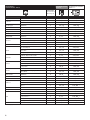
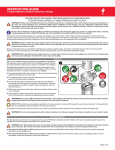
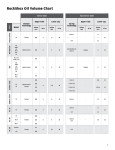
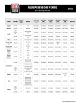
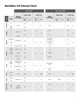
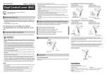
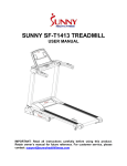
SPECIALIZED BICYCLE OWNER'S MANUAL APPENDIX A SUPPLEMENT 2014 RIDER/BIKE WEIGHT LIMITS AND TERRAIN CONDITIONS 2014 APPENDIX A SUPPLEMENT INTRODUCTION This Appendix A manual supplement is designed as an annual addition to the Appendix A section found in the Specialized Bicycle Owner’s Manual. This appendix is designed to help the rider differentiate between frame structural weight limits and braking distance weight limits. Each bike model is designed and tested to support a structural weight limit, which includes a cargo weight limit. As the weight of the rider approaches the structural weight limit of the bike, the allowable cargo weight might be reduced. For example, a bike may have a 55lb cargo weight limit, but if the weight of the rider is too close to the bike's structural weight limit, the rider may only be allowed to carry a smaller amount of cargo or no cargo at all. See following page for model-specific example and graphs. STRUCTURAL WEIGHT LIMIT CARGO WEIGHT RIDER WEIGHT 0 25 50 75 100 125 150 175 200 225 250 275 300 Additionally, CEN (European Committee for Standardization) has braking distance weight limits, which require that the combined weight of the rider and cargo can be stopped within a specified distance. Exceeding the max weight per CEN braking standards does not mean that the bike will not stop, but that it might not stop within the distance specified by CEN. The following information contains structural weight limits for frames, as well as recommended weight limits based on CEN standards for safe stopping distances. This information will also help determine if the rider and cargo weights are within the weight limits outlined in the Bike Model / Rider Weight Table (pages 5-6). UNDERSTANDING WEIGHT LIMITS FRAME STRUCTURAL WEIGHT LIMITS Structural weight limits for each bike are determined by Specialized Bicycles through extensive lab testing, and are listed in the Bike Model / Rider Weight Table. STRUCTURAL WEIGHT LIMIT: The maximum weight (rider and cargo) a bike can physically support. This limit is different from the MAX WEIGHT PER CEN BRAKING STANDARDS (see below). RIDER WEIGHT: The weight of the rider in riding gear (e.g., jacket, helmet cam, hydration pack, helmet, etc.). CARGO WEIGHT: The weight of any additional accessories (e.g., panniers, rear racks, saddle bags, handlebar bags, baskets, etc.) not accounted for in Rider Weight. CARGO WEIGHT LIMIT: The maximum cargo weight a bike has been tested to support structurally. TOTAL WEIGHT: The sum of Rider Weight and Cargo Weight. MAX WEIGHT PER CEN BRAKING STANDARDS Each bike model is tested to determine the maximum amount of weight (combined weight of Rider and Cargo) that can be applied to a bike and the capability to stop the bike within a prescribed distance. In situations where the weight limit for CEN braking standards does not exceed the structural weight limit, the maximum allowable weight limit is determined by the braking limit. In all other cases, the maximum allowable weight limit is determined by the structural weight limit. 1 DETERMINING MAXIMUM ALLOWABLE WEIGHT LIMITS 1. Find your bike in the Bike Model / Rider Weight Table. 2. Lookup the cargo weight limit and the Maximum Allowable Weight Limit of the bike model. 3. Determine the rider weight, which includes all riding gear. 4. Determine the cargo weight, which includes the weight of any additional accessories. 5. .Substract the rider weight from the recommended max weight. The result is the amount the rider is allowed for cargo weight, up to the cargo weight limit prescribed for the bike model. EXAMPLE: HARDROCK (Maximum Allowable Weight Limit = 300lb / 136kg. Cargo Weight Limit = 55lb / 25kg) STRUCTURAL WEIGHT LIMIT CARGO WEIGHT RIDER WEIGHT 0 25 50 75 100 125 150 175 200 225 250 275 300 Rider (255lb) + cargo (20lb) =275lb Total weight ok STRUCTURAL WEIGHT LIMIT CARGO WEIGHT RIDER WEIGHT 0 25 50 75 100 125 Rider (245lb) + cargo (55lb) = 300lb Total weight ok 150 175 200 225 250 275 300 STRUCTURAL WEIGHT LIMIT CARGO WEIGHT RIDER WEIGHT 0 25 50 75 100 125 150 175 200 225 250 275 290 300 275 300 Rider (290lb) + cargo (10lb) =300lb Total weight ok RIDE AT STRUCTURAL WEIGHT LIMIT CARGO WEIGHT RIDER WEIGHT 0 25 50 75 100 125 150 175 210 200 225 250 OWN RISK Rider (210lb) + cargo (65lb) = 275lb Total too heavy. Cargo weight exceeds cargo weight limit and has to be reduced. RIDE AT STRUCTURAL WEIGHT LIMIT CARGO WEIGHT RIDER WEIGHT 0 OWN RISK 25 50 75 100 125 150 175 200 225 250 275 310 300 225 250 275 310 300 Rider (255lb) + cargo (55lb) = (310lb) Total too heavy. Rider and/or cargo weight has to be reduced. RIDE AT STRUCTURAL WEIGHT LIMIT RIDER WEIGHT 0 OWN RISK 2 25 50 75 100 125 Rider (310lb) + no cargo = 310lb Rider weight exceed structural weight limit 150 175 200 INTENDED USE OF YOUR BICYCLE WARNING: Understand your bike and its intended use. Choosing the wrong bicycle for your purpose can be hazardous. Using your bike the wrong way is dangerous. No single type of bicycle is suited for all purposes. Your retailer can help you pick the “right tool for the job” and help you understand its limitations. There are many types of bicycles and many variations within each type. There are many types of mountain, road, racing, hybrid, touring, cyclocross and tandem bicycles. There are also bicycles that mix features. For example, there are road/racing bikes with triple cranks. These bikes have the low gearing of a touring bike, the quick handling of a racing bike, but are not well suited for carrying heavy loads on a tour, for which, you want a touring bike. Within each of type of bicycle, one can optimize the bicycle for certain purposes. Visit your bicycle shop and find someone with expertise in the area that interests you. Do your own homework. Seemingly small changes such as the choice of tires can improve or diminish the performance of a bicycle for a certain purpose. On the following pages, we generally outline the intended uses of all bike types and, based in part on max weight per CEN braking standards, we specify the maximum rider weights by bike family/model. Industry usage conditions are generalized and evolving. Consult your dealer about how you intend to use your bike. HIGH-PERFORMANCE ROAD 9ED:?J?ED'0Bikes designed for riding on a paved surface where the tires do not lose ground contact. ?DJ;D:;:0To be ridden on paved roads only. DEJ?DJ;D:;:0For off-road, cyclocross, or touring with racks or panniers. JH7:;E<<0Material use is optimized to deliver both light weight and specific performance. You must understand that (1) these types of bikes are intended to give an aggressive racer or competitive cyclist a performance advantage over a relatively short product life, (2) a less aggressive rider will enjoy longer frame life, (3) you are choosing light weight (shorter frame life) over more frame weight and a longer frame life, (4) you are choosing light weight over more dent resistant or rugged frames that weigh more. All frames that are very light need frequent inspection. These frames are likely to be damaged or broken in a crash. They are not designed to take abuse or be a rugged workhorse. See also Appendix B. GENERAL PURPOSE RIDING 9ED:?J?ED(0Bikes designed for riding Condition 1, plus smooth gravel roads and improved trails with moderate grades where the tires do not lose ground contact. ?DJ;D:;:0For paved roads, gravel or dirt roads that are in good condition, and bike paths. DEJ?DJ;D:;:0For off-road or mountain bike use, or for any kind of jumping. Some of these bikes have suspension features, but these features are designed to add comfort, not off-road capability. Some come with relatively wide tires that are well suited to gravel or dirt paths. Some come with relatively narrow tires that are best suited to faster riding on pavement. If you ride on gravel or dirt paths, carry heavier loads or want more tire durability talk to your dealer about wider tires. CYCLO-CROSS 9ED:?J?ED(0Bikes designed for riding Condition 1, plus smooth gravel roads and improved trails with moderate grades where the tires do not lose ground contact. ?DJ;D:;:0For cyclo-cross riding, training and racing. Cyclo-cross involves riding on a variety of terrain and surfaces including dirt or mud surfaces. Cyclo-cross bikes also work well for all weather rough road riding and commuting. DEJ?DJ;D:;:0For off road or mountain bike use, or jumping. Cyclo-cross riders and racers dismount before reaching an obstacle, carry their bike over the obstacle and then remount. Cyclo-cross bikes are not intended for mountain bike use. The relatively large road bike size wheels are faster than the smaller mountain bike wheels, but are not as strong. CROSS-COUNTRY, MARATHON, HARDTAILS 9ED:?J?ED)0Bikes designed for riding Conditions 1 and 2, plus rough trails, small obstacles, and smooth technical areas, including areas where momentary loss of tire contact with the ground may occur. NOT for jumping. All mountain bikes without rear suspension are Condition 3, as well as some lightweight rear suspension models. ?DJ;D:;:0For cross-country riding and racing which ranges from mild to aggressive over intermediate terrain (e.g., hilly with small obstacles like roots, rocks, loose surfaces, hard pack and depressions). Cross-country and marathon equipment (tires, shocks, frames, drive trains) are light-weight, favoring nimble speed over brute force. Suspension travel is relatively short since the bike is intended to move quickly on the ground. DEJ?DJ;D:;:0For Hardcore Freeriding, Extreme Downhill, Dirt Jumping, Slopestyle, or very aggressive or extreme riding. Not for spending time in the air, landing hard and hammering through obstacles. JH7:;E<<0Cross-Country bikes are lighter, faster to ride uphill, and more nimble than All-Mountain bikes. Cross-Country and Marathon bikes trade off some ruggedness for pedaling efficiency and uphill speed. 3 ALL MOUNTAIN 9ED:?J?ED*0Bikes designed for riding Conditions 1, 2, and 3, plus rough technical areas, moderately sized obstacles, and small jumps. ?DJ;D:;:0For trail and uphill riding. All-Mountain bicycles are: (1) more heavy duty than cross country bikes, but less heavy duty than Freeride bikes, (2) lighter and more nimble than Freeride bikes, (3) heavier and have more suspension travel than a cross country bike, allowing them to be ridden in more difficult terrain, over larger obstacles and moderate jumps, (4) intermediate in suspension travel and use components that fit the intermediate intended use, (5) cover a fairly wide range of intended use, with models that are more or less heavy duty. Talk to your retailer about your needs and these models. DEJ?DJ;D:;:0For use in extreme forms of jumping/riding such as hardcore mountain, Freeriding, Downhill, North Shore, Dirt Jumping, Hucking etc. Not for large drop offs, jumps or launches (wooden structures, dirt embankments) requiring long suspension travel or heavy duty components; and not for spending time in the air landing hard and hammering through obstacles. JH7:;E<<0All-Mountain bikes are more rugged than cross country bikes, for riding more difficult terrain. All-Mountain bikes are heavier and harder to ride uphill than cross country bikes. All-Mountain bikes are lighter, more nimble and easier to ride uphill than Freeride bikes. All-Mountain bikes are not as rugged as Freeride bikes and must not be used for more extreme riding and terrain. GRAVITY, FREERIDE AND DOWNHILL 9ED:?J?ED+0Bikes designed for jumping, hucking, high speeds, or aggressive riding on rougher surfaces, or landing on flat surfaces. However, this type of riding is extremely hazardous and puts unpredictable forces on a bicycle which may overload the frame, fork, or parts. If you choose to ride in Condition 5 terrain, you should take appropriate safety precautions such as more frequent bike inspections and replacement of equipment. You should also wear comprehensive safety equipment such as a full-face helmet, pads, and body armor. ?DJ;D:;:0For riding that includes the most difficult terrain that only very skilled riders should attempt. Gravity, Freeride, and Downhill are terms which describe hardcore mountain, north shore, slopestyle. This is “extreme” riding and the terms describing it are constantly evolving. Gravity, Freeride, and Downhill bikes are: (1) heavier and have more suspension travel than All-Mountain bikes, allowing them to be ridden in more difficult terrain, over larger obstacles and larger jumps, (2) the longest in suspension travel and use components that fit heavy duty intended use. There is no guarantee that extreme riding will not break a Freeride bike. The terrain and type of riding that Freeride bikes are designed for is inherently dangerous. Appropriate equipment, such as a Freeride bike, does not change this reality. In this kind of riding, bad judgment, bad luck, or riding beyond your capabilities can easily result in an accident, where you could be seriously injured, paralyzed or killed. DEJ?DJ;D:;:0To be an excuse to try anything. Read Section 2. F of the Bicycle Owner’s Manual, p. 12. JH7:;E<<0Freeride bikes are more rugged than All-Mountain bikes, for riding more difficult terrain. Freeride bikes are heavier and harder to ride uphill than All-Mountain bikes. DIRT JUMP 9ED:?J?ED+0Bikes designed for jumping, hucking, high speeds, or aggressive riding on rougher surfaces, or landing on flat surfaces. However, this type of riding is extremely hazardous and puts unpredictable forces on a bicycle which may overload the frame, fork, or parts. If you choose to ride in Condition 5 terrain, you should take appropriate safety precautions such as more frequent bike inspections and replacement of equipment. You should also wear comprehensive safety equipment such as a full-face helmet, pads, and body armor. ?DJ;D:;:0For man-made dirt jumps, ramps, skate parks other predictable obstacles and terrain where riders need and use skill and bike control, rather than suspension. Dirt Jumping bikes are used much like heavy duty BMX bikes. A Dirt Jumping bike does not give you skills to jump. Read Section 2. F of the Bicycle Owner’s Manual, p. 12. DEJ?DJ;D:;:0For terrain, drop offs or landings where large amounts of suspension travel are needed to help absorb the shock of landing and help maintain control. JH7:;E<<0Dirt Jumping bikes are lighter and more nimble than Freeride bikes, but they have no rear suspension and the suspension travel in the front is much shorter. KIDS Bikes designed to be ridden by children. Parental supervision is required at all times. Avoid areas involving automobiles, and obstacles or hazards including inclines, curbs, stairs, sewer grates or areas near drop-offs or pools. The Hotwalk Owner's Manual is available as a separate document, supplied with the Hotwalk bikes 4 BIKE MODEL / RIDER WEIGHT TABLE MAXIMUM CARGO WEIGHT MAXIMUM ALLOWABLE WEIGHT 4, 5 CATEGORY (See Intended Use Page 3) Alias All Models 1 5 / 2.3 1 240 / 109 3 S-Works 1 30 / 14 2 240 / 109 3 Expert, Race, Elite INT, Sport INT, Comp 1 30 / 14 2 275 / 125 Elite, Sport, Base * 1 30 / 14 2 220 / 100 3 * Sport, Sora * 1 5 / 2.3 220 / 100 3 * S-Works, Pro, Expert, Comp 1 5 / 2.3 1 240 / 109 3 Ariel All Models 2 55 / 25 300 / 136 AWOL AWOL Rare 2 55 / 25 300 / 136 S-Works, Expert 4 5 / 2.3 240 / 109 3 Comp Carbon 4 5 / 2.3 1 275 / 125 1 300 / 136 Allez Amira Camber FSR 1 1 EVO, Comp, Base 4 5 / 2.3 Crave All Models 3 30 / 14 2 300 / 136 Crossover All Models 2 55 / 25 300 / 136 Crossroads All Models 2 55 / 25 300 / 136 CrossTrail All Models 2 55 / 25 300 / 136 S-Works, Pro, Expert, Elite 2 5 / 2.3 240 / 109 3 Sport Carbon 105 2 5 / 2.3 1 275 / 125 Sport Apex Disc 2 30 / 14 2 275 / 125 Sora * 2 30 / 14 All Models * 2 55 / 25 220 / 100 3 * S-Works 5 5 / 2.3 240 / 109 3 I, II 5 5 / 2.3 1 300 / 136 I Carbon 5 5 / 2.3 1 275 / 125 Comp INT, Elite INT, Sport INT (Shimano Brakes) 1 55 / 25 275 / 125 Comp, Elite, Sport, Base * 1 55 / 25 220 / 100 3 * S-Works, Expert Carbon 4 5 / 2.3 1 240 / 109 3 Expert EVO, Comp, EVO 4 5 / 2.3 1 300 / 136 S-Works, Marathon Carbon, Expert Carbon 3 5 / 2.3 1 240 / 109 3 Comp Carbon 3 5 / 2.3 1 275 / 125 Comp 3 5 / 2.3 1 300 / 136 Base, all models 2 55 / 25 300 / 136 Step Through, all models 2 55 / 25 240 / 109 Fatboy All Models 3 55 / 25 275 / 125 Fate All Models 3 5 / 2.3 1 240 / 109 3 Hardrock All Models 3 55 / 25 300 / 136 24" XC Models 3 55 / 25 220 / 100 24" 21spd, 7spd, street; 20" 6spd, Coaster 6 30 / 14 2 220 / 100 16" and 12" Coasters 6 30 / 14 CruX Daily Demo FSR Dolce Enduro FSR Epic FSR Expedition Hotrock Jett Langster 1 2 1 2 220 / 100 3 * 100 / 45 Hotwalk boy/girl 6 0/0 40 / 18 All Models 3 55 / 25 300 / 136 Pro 1 30 / 14 2 240 / 109 3 Base * 1 30 / 14 2 265/120 3 * Street * 1 30 / 14 220 / 100 3 * 2 5 BIKE MODEL / RIDER WEIGHT TABLE MAXIMUM CARGO WEIGHT MAXIMUM ALLOWABLE WEIGHT 4, 5 CATEGORY (See Intended Use Page 3) Myka HT All Models 3 55 / 25 300 / 136 P.Slope, P.3, P.26 AM, P.Street 5 0/0 300 / 136 P.20, P.18, P.Grom 5 0/0 220 / 100 Rockhopper All Models 3 55 / 25 300 / 136 Roll All Models * 1 30 / 14 2 220 / 100 3 * Roubaix All Models 1 5 / 2.3 1 240 / 109 3 Ruby All Models 1 5 / 2.3 1 240 / 109 3 Rumor FSR All Models 4 5 / 2.3 240 / 109 3 Safire FSR All Models 3 5 / 2.3 1 300 / 136 Expert 1 55 / 25 240 / 109 3 Comp, Elite, Sport INT, Sport Disc 1 55 / 25 275 / 125 Base, X3, Sport * 1 55 / 25 220 / 100 3 * All Models * 1 5 / 2.3 1 220 / 100 3 * Pro, SL4, Expert 1 55 / 25 240 / 109 3 Comp Disc, Elite Disc, Elite INT, Sport, Sport Disc 2 55 / 25 300 / 136 Comp, Comp Carbon, Elite, Base * 2 55 / 25 265 / 120 3 * S-Works, Expert Carbon, Elite 4 5 / 2.3 240 / 109 3 Comp Carbon 4 5 / 2.3 1 275 / 125 Comp 4 5 / 2.3 1 300 / 136 S-Works, Marathon, Expert, Carbon SS 3 5 / 2.3 1 240 / 109 3 SJ HT Comp Carbon 3 5 / 2.3 1 275 / 125 Comp, EVO 3 30 / 14 2 300 / 136 P.Series Secteur Shiv Sirrus SJ FSR SJ HT 1 1 LTD Disc, Pro Disc 2 55 / 25 275 / 125 Source Eleven, Expert, Comp, Eight, Elite, Seven, Sport, Base 2 55 / 25 300 / 136 Status FSR All Models 5 30 / 14 2 300 / 136 Tarmac All Models 1 5 / 2.3 240 / 109 3 Transition All Models * 1 5 / 2.3 1 220 / 100 3 * Comp Disc 1 55 / 25 240 / 109 3 Elite Disc, Sport Disc 1 55 / 25 275 / 125 Base * 1 55 / 25 220 / 100 3 * Turbo All Models 2 55 / 25 300 / 136 Venge All Models 1 5 / 2.3 1 240 / 109 3 Pro Carbon 1 5 / 2.3 1 240 / 109 3 Expert Carbon 2 5 / 2.3 1 275 / 125 Comp Carbon * 2 5 / 2.3 1 220 / 100 3 * Comp, Base Sport * 2 55 / 25 265 / 120 3 * Elite, Sport Disc 2 55 / 25 300 / 136 All Models * 2 55 / 25 271 / 124 3 * TriCross Vita Work See following page for footnotes 6 1 FOOTNOTES 1 Seat Bag Only. 2 For ALLOY bikes manufactured without original equipment dropout rack mounts: A rear rack can be installed with the use of separate rack mount clips. Cargo capacity with separate mounting clips is limited to 30lb / 14kg. 3 STRUCTURAL WEIGHT LIMITS FOR FRAMES: 275lb / 125Kg 300lb / 126Kg Drop bar equipped carbon or alloy road bikes Alloy mountain bikes Carbon or alloy cyclocross bikes Flat bar equipped alloy hybrid / city bikes Carbon or alloy triathlon / aero / time trial bikes Flat bar equipped carbon hybrid / city bikes Carbon mountain bikes If any weight-bearing Specialized-branded carbon components (i.e. handlebar, seatpost, stem, crank, saddle, rim) are present, then the weight limit is 240lb / 109kg. This does not include non-weight-bearing carbon components such as brake levers, chainrings, bottle cages, etc. Roval wheels (complete wheelsets) are made to be lightweight, and are not suitable for all riders and all possible uses. If any Roval wheelsets are present, the rider (plus cargo) weight limit is 240lb (109Kg). Failure to follow this warning may result in a catastrophic failure of the wheel. * MODELS: The Maximum Allowable Weight Limit for these models are determined by CEN standards for stopping distance. The Structural Weight Limit for a particular model can exceed this maximum limit for stopping distance (see STRUCTURAL WEIGHT LIMITS FOR FRAMES, above). If a rider's weight is above the Maximum Allowable Weight Limit but below the Structural Weight Limit, the rider would be able to use the bike from a structural standpoint, but with reduced braking that does not conform to CEN requirements. IMPORTANT: Braking limits do not change regardless of carbon or alloy components. 4 Recommended max weights are based on European (CEN) testing standards (for cargo and rider only). 5 CEN braking standards are based on the brakes specified on the bike models from the manufacturer. Changing the brakes can result in an increase or decrease in the braking distance. WARNING: For riders at the RIDER WEIGHT LIMIT, you may not be able to carry cargo if the TOTAL WEIGHT LIMIT is exceeded. SPECIALIZED BICYCLE COMPONENTS 15130 Concord Circle, Morgan Hill, CA 95037 (408) 779-6229 0000037057_OM_EN R2, 09/13 Please note all instructions are subject to change and updates without notice. Please visit www.specialized.com for periodic tech updates. Feedback: [email protected] 7 INSTRUCTION GUIDE S-WORKS ROAD CARBON CRANKSET (Carbon and Alloy OSBB cups) THIS BRIEF INSTRUCTION GUIDE CONTAINS IMPORTANT INFORMATION. PLEASE READ CAREFULLY AND STORE IN A SAFE PLACE. Congratulations! The S-Works Carbon crankset you have chosen is among the finest advanced composite products available in cycling. Carbon fiber is a very special material that requires particular care during assembly, storage and riding. This instruction guide contains instructions and warnings, plus torque specifications, to be used in conjunction with the owner’s manuals and instruction guides supplied with your bicycle. Please visit http://servicevideos.specialized.com/ for instructional videos. WARNING! Failure to follow these instructions may result in a catastrophic failure of the crank, frame and/or its components while riding, which may result in serious personal injury or death. WARNING! Bicycle assembly is a complicated task which requires training and experience. Do not attempt installation of any component if you do not have experience and training as a bicycle mechanic. Failure to follow this warning may result in serious personal injury or death. Reference should also be made to Barnett’s or some other comprehensive bicycle manual. WARNING! Failure to follow the torque specifications in this instruction guide will void your warranty, but most importantly may result in damage to the crank, which may not be visible. If the crank is damaged, this can result in loss of structural integrity, which may result in serious personal injury or death. To ensure the best assembly possible and to prevent any damage to the crank components, follow all torque specifications. TOOLS REQUIRED: 1.5mm, 4mm, 6mm and 12mm Allen key OSBB Bearing Press Tool (S125300012) or... T25, T30 and T45 Torx key Specialized MindSet Headset Bearing Press (#9895-3045) 17mm and 20mm wrench Torque wrench (3/8” socket) Specialized Carbon Crank Tool Kit (Bearing pullers, lockring tool, 6mm Allen and T45 Torx keys, 8mm-to-3/8” adapter - #9891-3000) Ratchet wrench (3/8” socket) 3M DP 420 Epoxy packet (includes epoxy, alcohol wipe and applicator) High quality grease Threadlocker (Blue 242, Green 640) FRAME PREPARATION CAUTION: Do not face or ream bottom bracket shell! This can possibly prevent proper installation of the crank. Your Specialized frame does not require any bottom bracket shell pre-installation preparation, as all surfaces have been precisely machined to specific tolerances at the factory for proper interface with the S-Works Carbon crankset. CHAINRING INSTALLATION To achieve optimal shifting, it’s very important to ensure proper pairing and orientation of the chainrings. Chainrings are offered in several different configurations. Spiders are offered in alloy or carbon, in 110mm or 130mm BCD options. Contact your Specialized Authorized Dealer, or visit www.specialized.com for available options. SRM kits are available separately through SRM. Cranks and rings sold separately. Specialized chainrings are paired specifically to ensure that the clocking of the teeth match properly between the large and small ring. Mixing various configurations of chainrings can result in poor shifting performance. To achieve optimal shifting performance, ensure that the counter-sunk surfaces of the bolt holes are facing away from each other. The large chainring pin and the small chainring “bump” must line up with the crank arm (see “INSTALLING THE SPIDER AND LOCKRING”, P.4). The S-Works carbon spider bolt holes require proprietary Specialized chainring bolts (# S091600017). Apply blue threadlocker, use T30 Torx and flat head screwdriver. Standard chainring bolts: Use T30 Torx and 6mm Allen keys to tighten or loosen the bolts. Recommended torque for chainring bolts: 87 in-lbf (9.8 N*m). WARNING! Great care should be taken to not damage carbon fiber or composite material. Any damage may result in a loss of structural integrity, which may result in a catastrophic failure. This damage may or may not be visible in inspection. Before each ride, and after any crash, you should carefully inspect your crank for any fraying, gouging, scratches through the paint, chipping, bending, or any other signs of damage. Do not ride if your crank shows any of these signs. After any crash, and before you ride any further, take your bicycle to an Specialized Authorized Dealer for a complete inspection. WARRANTY For the complete warranty provisions, please refer to www.specialized.com. COMPATIBILITY Carbon frames with 61mm width carbon OSBB bottom bracket shell and press-in cups p.2 Carbon frames with 68mm width alloy OSBB bottom bracket shell and snap-ring slots p.3 Additional documents: After-market crank compatibility / adapter instruction guide Carbon road frame instruction guide SPECIALIZED BICYCLE COMPONENTS 15130 Concord Circle, Morgan Hill, CA 95037 (408) 779-6229 IG0338 Rev.C, December 2012 Please note all instructions are subject to change for improvement without notice. Please visit www.specialized.com for periodic tech updates. Feedback: [email protected] Page 1 of 5 INSTALLING THE BOTTOM BRACKET (61 x 46mm BB shell, press-in cups) The following setup is for frames with 61mm width carbon shells that require press-in cups. See note on page 3 for additional information 1 2 3 4 5 4 5 6 7 9 8 10 11 12 1. Non-drive-side crank arm2 2. Non-drive-side adjustable cover2 3. Non-drive-side conical spacer2 1 Road or MTB compatible 4. 42 x 30 x 7mm bearing1 5. OSBB press-in cup2 6. Drive-side alloy bearing spacer2 2 Road compatible only 7. Spider lockring 8. Drive-side crank arm spider 9. Steel retainer nut 1 10. M12 steel center bolt2 11. Drive-side crank arm2 2 1 12. Drive-side crank cover screw1 2 1 OSBB Road Press-in Cup (#S100400001) Cartridge Bearing 42 x 30 x 7mm (#S091600016) Headset Bearing Press (#9895-3045 or S125300012) 1. Remove any grease from the carbon bottom bracket shell. 2. Finish cleaning the bottom bracket shell with an alcohol wipe. 3. Prepare the cranks for installation: Pre-install the spider, chainrings, spindle nut and spindle bolt. Pre-grease and install the crank parts in the correct order as shown on page 4. NOTE: Due to the 20 minute work time of the epoxy, the cranks must be installed immediately after the cups are installed, to ensure that the cups, bearings and crank are aligned. 4. Fully mix the 3M DP 420 2-part epoxy, then apply the epoxy to the outer surface of the OSBB cups and the first 10mm of the inner diameter of the carbon bottom bracket shell. 5. Press the cups into the bottom bracket shell until the cups lightly bottom out against the frame (fig.1). Use either the Specialized Bottom Bracket Bearing Press (S125300012) or the Mindset Headset Bearing Press tool (9895-3045). When using the 9895-3045 tool, either use a Park Headset Press Tool or a bench-mounted vise to press the cups into the frame. Be sure to press the cups evenly into the frame. 6. Wipe off the excess epoxy from the inside and outside flanges of the cups. Use an alcohol wipe to clean off any remaining residue. 7. Apply grease to the outer diameter of the OSBB bearings, then press them into the cups using the same tool that pressed the cups into the frame (fig.2). Be sure to press the bearings in straight. Do not force the bearings into the cup. Wipe any last epoxy residue from the outside of the cup. 8. Once the bearings bottom out inside the cups, do not apply any more pressure. Excess force can damage the cups and can cause the bearings to spin roughly. 9. To remove the cups from the frame, pull the bearings out as shown on page 5, then lightly tap the backside of the cups in a circular pattern with a large flat surface. Do not use a screwdriver, as it may damage the cups. 10. Before installing new cups with new epoxy, remove any excess epoxy lips that may have formed at the inside and outside edges of the cups. TECH TIP: Any thin epoxy residue that remains on the contact area of the carbon shell should not be removed. This thin film of epoxy residue can actually benefit the bond of fresh epoxy when installing new cups. Page 2 of 5 INSTALLING THE BOTTOM BRACKET (68 x 42mm alloy BB shell, with circlips) The following setup is for frames with 68mm width alloy shells that require snap-rings. See note on page 3 for additional information 2 1 1. Non-drive-side crank arm2 4. 42 x 30 x 7mm bearing1 7. Spider lockring 1 10. M12 steel center bolt2 3 2. 4 5 4 5 Non-drive-side adjustable cover2 5. Snap-ring1 8. Drive-side crank arm spider 2 11. Drive-side crank arm2 6 7 9 8 10 11 12 3. Non-drive-side conical spacer2 1 Road or MTB compatible 6. Drive-side alloy bearing spacer2 2 Road compatible only 9. Steel retainer nut 1 12. Drive-side crank cover screw1 2 1 Snap-rings Cartridge Bearing 42 x 30 x 7mm (#S091600016) Mindset Headset Bearing Press (#9895-3045) 1. Install the snap-rings into the snap-ring grooves in the BB shell (fig.1). 2. Apply green threadlocker # 640 to the outer diameter of the OSBB Bearings and inner diameter of the OSBB shell. 3. Press the bearings into the shell (fig.2). Be sure to press the bearings in straight, use a bearing press tool (9895-3045 or S125300012) to guide the bearings in straight. Do not force the bearing into the shell. 4. Once the bearings have bottomed out against the snap-rings, do not apply any more pressure. Too much force applied to the bearings once bottomed out can cause damage to the snap-rings and can cause the bearings to spin roughly. NOTE: Earlier generation cranks are equipped with a cap and wave washer. Newer generation cranks are equipped with an adjustable cover and conical spacer (#2 and #3). The adjustable cover and conical spacer are available separately to replace the cap and wave washer. 1st generation 2nd generation Page 3 of 5 INSTALLING THE SPIDER AND LOCKRING SPIDER LOCKRING ASSEMBLY SPIDER & CHAINRING ALIGNMENT 1 2 3 Use blue threadlocker #242 on lockring threads. Install lockring with step facing out. NOTE: Orientation text must be visible once installed. 1. 2. 3. 4. Spider chamfer Drive-side crank arm Small ring bump Large ring pin 4 INSTALLING THE CRANKSET (73 x 46mm BB shell, press-in cups) 1 NOTE: Crank bolt is MTBor Road-specific. MTB Bolt: 20g (small hole) Road Bolt: 16g (large hole) 2 (Reverse thread) 6 2 Bottom Bracket Shell 3 Conical sides face each other Step side faces bearing Install the non-drive-side cover (2) and conical spacer (3) on the non-drive-side spindle. The cover only fits one way, with the “ALIGN CRANK” text hidden by the crank arm. Install the bearing spacer (6) on the drive-side spindle. 3 Liberally grease the spacers, bolt threads and spline surfaces before installation. To increase torque accuracy, ensure that the bolt head surface is greased. 4 Non-drive-side cover ч 2010 ч 2010 ш 2011 Crank arm ш 2011 Tighten using a 6mm Socket Allen Key with Torque Wrench. Crank arm removal: reverse steps 3 & 4. Page 4 of 5 Install the bolt hole cover screw. Hand tighten lightly. Adjust the preload on the non-drive-side cover by tightening the three 1.5mm Allen screws in an even, alternating pattern, until there is no lateral movement in the crank, and the bearings still spin freely. Do not overtighten. REMOVING THE BEARINGS FROM THE CRANK SPINDLE NOTE: Removal of the crank arms can result in the bearings remaining in the BB shell or on the spindle. Choose the according tool for the job. 1 2 Open the two halves and place over the axle shaft and bearing. Close the two halves over the bearing. 3 4 Continue tightening the center bolt, or... Turn the body of the tool assembly while keeping the center bolt from turning until the bearing slides off the axle. Tighten the two pinch bolts to lock the tool around the bearing. Turn the center bolt clockwise until it contacts the crank axle. REMOVING THE BEARINGS FROM THE BOTTOM BRACKET SHELL 1 Angle the expander tip into the bearing, then pull back until the lip of the expander seats against the bearing. 2 Thread the expander bolt into the expander tip. Do not overtighten the expander bolt. 3 Install the bearing receptor sleeve over the expander assembly. 4 5 Thread the nut onto the expander assembly with a 17mm wrench, while holding the expander assembly with a 20mm wrench. Page 5 of 5 INSTRUCTION GUIDE INTERNAL CABLE ROUTING - SHIFTER & BRAKE (TARMAC SL4 / ROUBAIX SL4 / AMIRA SL4 / RUBY / CRUX CARBON) THIS INSTRUCTION GUIDE CONTAINS IMPORTANT INFORMATION. PLEASE READ CAREFULLY AND STORE IN A SAFE PLACE. WARNING! Please read the following instructions. Bicycle assembly is a complicated task, which requires training and experience. If you have any doubt regarding your mechanical ability and/or installation of this product, visit your Specialized Authorized Dealer. Specialized recommends that the cable system be installed by a qualified mechanic. Failure to follow this warning may result in serious personal injury or death. Please read the following warnings. Failure to follow the warnings in this instruction guide may result in a catastrophic failure, resulting in serious personal injury or death. This phrase may not be repeated in connection with each and every warning. Please visit http://servicevideos.specialized.com/ for instructional videos. WARRANTY For the warranty provisions of this product, please visit www.specialized.com. MECHANICAL SHIFTING PRE-INSTALLING THE CABLE AND HOUSING Frames with cables pre-installed: Routing sheaths are included in the box for future cable replacements. Frames without cables pre-installed: Routing sheaths are pre-installed in the frame to facilitate the routing of the cable through the frame. To simplify the replacement of worn cables, it is recommended to route the sheaths onto the cables and through the frame before removing the cables. INSTALLING THE DERAILLEUR HOUSINGS, BARREL ADJUSTERS AND CABLES 2 1 3 B C D E F G A H I I 1” (25mm) A California Cross C D E Fig. 1: Decide to which side of the down tube each cable will be routed. The cables can go from the shifters to either side of the down tube. If the cable housings cross each other to the opposite sides of the down tube (California Cross), the cables will have to cross again inside the down tube (Fig. 3). More than a single cross inside the down tube will cause the cables to wind around each other and impede proper shifting. Fig. 1: Cut the cable housing to the required length so that the handlebars can rotate fully past 90° in each direction without pulling on the housings. Fig. 2: Cut out a section of housing (see inset) that equals the inner length of the barrel adjusters (approximately 1”) at the desired location along the length of each shifter cable housing. Avoid placing the barrel adjusters too close to the shifters or the ICR stops. Remove the bottom bracket cable guide (if it’s pre-installed). Leave the sheaths in the down tube; they are designed to ease installation of the cables. Install the cable (A) in the shifter as instructed in the shifter instruction guide (provided by the shifter manufacturer). Fig. 2: Install a housing ferrule (B) and the first part of cable housing (C), followed by the barrel adjuster (D) and the second piece of housing (E). Fig. 2: Install a housing ferrule (F) on the second piece of housing. Fig. 2: Install a plastic mini-sheath (G), then install a cable housing guide hat (H). Fig. 3: Run the cables (A) through the routing sheaths (I) until they exit the down tube at the bottom bracket. Once routed, remove the sheaths. SPECIALIZED BICYCLE COMPONENTS 15130 Concord Circle, Morgan Hill, CA 95037 (408) 779-6229 IG0377 Rev.B, August 2012 Please note all instructions are subject to change for improvement without notice. Please visit www.specialized.com for periodic tech updates. Feedback: [email protected] Page 1 of 4 ROUTING THE DERAILLEUR CABLES IN THE BOTTOM BRACKET CABLE GUIDE 4 - Tarmac/Amira/Roubaix SL4 4 - Roubaix SL4 Disc 4 - Ruby 4 - CruX Carbon J Disc brake K K Disc brake J J J K K L L L M M M L M Install the front and rear derailleurs on the frame as instructed in the derailleur manufacturer’s instruction guide. Fig. 4: Route the front derailleur cable coming out of the down tube hole through the non-drive-side portion of the bottom bracket cable guide (J), and up through the front derailleur cable guide hole. Make sure the cables are not crossing each other more than once inside the down tube (Fig. 1). Fig. 4: Route the rear derailleur cable coming out of the down tube through the drive-side portion of the bottom bracket cable guide (K), then through the chainstay routing sheath. Fig. 4: Place the cable guide bridge or cover (L) over the cable guides and install the bolt (M). Torque to 25 in-lbf (2.8 N*m). 5 7 6 I A I 8 S R S Q Trim the rear derailleur cable housing to the required length for the rear derailleur to function properly. Fig. 5, 6: Once the cable comes out the drive-side dropout hole, remove the routing sheath. Fig. 7: Install the extended dropout guide (Q) (notch pointing up), followed by the cable ferrule (R) and cable housing (S). Fig. 8: Route the rear derailleur cable housing to the rear derailleur and insert the cable into the derailleur. Adjust the cable position for proper shifting and torque the cable bolt according to the manufacturer’s torque specification. Page 2 of 4 ELECTRONIC SHIFTING INSTALLING THE ELECTRONIC WIRING Electronic shifting installation instructions are provided by the shifting system manufacturer. The following information covers steps that are specific to Specialized road frames, and are designed to be applied in conjunction with the manufacturer instructions Fig. 1: Route the rear derailleur wire through the dropout. All other wires should be routed as shown in the Shimano Di2 technical documents. Fig. 2: The rear derailleur wire must go over the top and around the front of the bottom bracket shell. To achieve this, it will be necessary to rotate the frame so that the chainstay is vertical and the front of the frame is pointed toward the ground. Fig. 3: Route each wire so that all wires exit the frame through the hole at the bottom of the down tube. Fig. 4: Connect each wire to its matching color-coded wire on Junction B, with a heat-shrink tube placed over each cable junction. Fig. 5: Once all the wires are connected to Junction B, re-insert the box and wires back through the down tube hole and into the frame. Fig. 6: Insert the split rubber grommet over the rear derailleur wire and insert it into the dropout hole. Repeat at the head tube/down tube hole. Follow the remaining steps in the Shimano Di2 technical documents. 1 3 2 To front derailleur To rear derailleur 4 5 To battery (bottle cage option) To Junction A. See Shimano document SM-EW79A-E To battery (bottom bracket option) Split grommet 6 Junction B MOUNTING THE BATTERY AT THE BOTTOM BRACKET Specialized offers different options for mounting the battery, by either using a water bottle bracket, or a bottom bracket mounted bracket. When running a bottom bracket mounted battery, tuck the wires and junction box back into the large bottom bracket hole, except the battery wire. Tarmac/Amira/ Roubaix SL4 Ruby Replace the Shimano battery bracket with the custom Specialized battery bracket (A). Connect the battery mounting assembly (B) to the junction box battery wire. C Place the custom Specialized bottom bracket mounting bracket (C) that matches the frame into the bottom bracket cavity. Place the serrated washer between the battery bracket and the mounting bracket (D). C D D A B A B Bolt the battery bracket to the frame (E). Finish tucking the battery wire up into the large bottom bracket hole. E E Page 3 of 4 INSTALLING THE REAR BRAKE RIM BRAKES: 1 A 2 G A F B C D E F Fig. 1: Install the brake cable (A), cable housing (B), brake cable housing ferrule (C), plastic mini-sheath (D) and cable housing guide hat (E). Fig. 1: Route the cable through the sheath (F) and through the brake ICR stop hole in the top tube, then remove the sheath. TECH TIP: To prevent brake cable rattle, it is recommended to install three rubber donuts onto a piece of routing sheath (approximate length 8” [20cm]), then install the sheath with the three donuts onto the cable and through the ICR hole at the top tube/seat tube junction. Fig. 2: Install the brake ICR stop (G), then torque the stop in place (10 in-lbf (1.1 N*m). Trim the cable housing to the required length and install the housing. Fasten the cable as instructed in the brake manufacturer’s instruction guide. DISC BRAKES WITH PARTIAL HOUSING (compatible CruX and Roubaix models only): 1 CruX Carbon 2 3 M To brake caliper L K To brake lever (A) A B C H D E I F J Fig. 1: Install the brake cable (A), cable housing (B), housing ferrule (C), mini-sheath (D) and guide hat (E), then run the cable through the sheath (F). Fig. 2: Remove the sheath, then route the cable through the bottom bracket brake cable guide (H). Install the guide door or bridge (I) and bolt (J). Install the cable into the chainstay sheath. Once the cable exits through the brake ICR stop hole in the chainstay, remove the sheath. Fig. 3: Install the cable noodle (K), followed by a housing ferrule (L). Trim a section of brake cable housing (M) to the required length and install the housing. Install the housing on the cable, then fasten the cable to the brake caliper as instructed in the brake manufacturer’s instruction guide. DISC BRAKES WITH FULL HOUSING (compatible CruX and Roubaix models only): 1 Roubaix SL4 Disc 2 3 To brake caliper B To brake lever (A) B B A A Fig. 1: Place a guide hat (A) on the housing (B), then route the housing into the down tube ICR guide hole. Fig. 2: Route the housing through the bottom bracket cable guide holes. Do not use the supplied cable guide. Fig. 3: Continue installing the housing into the non-drive-side chainstay. Once the housing exits through the brake ICR stop hole in the chainstay, install a guide hat (A) on the housing (B). Trim the housing to the desired length, then connect the housing to the caliper as instructed in the brake manufacturer’s instruction guide. Page 4 of 4