1
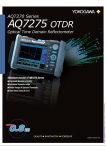
High-Speed Data Acquisition Unit
NEW
MS/s
Isolated
Maximum sample rate 100 MS/s12bit
Inputs
-Year
ear Warrant
Warranty
Bulletin 7201-20E
www.yokogawa.com/tm/
Subscribe to "Newswave" our free e-mail newsletter
100
16 ch
Maximum sample rate
Fast Acquisition, Transfer, and S torage
Finally, a No-Compromise, High-P erformance Data Acquisition Unit
Selecting a data acquisition platform for your electronics or mechatronics application has always
been a balancing act. High speed digitizers lack the isolation, attenuation, or bit resolution necessary
for power electronics testing. PC-based platforms with fast streaming throughput sacrifice noise
immunity, signal conditioning, and hardware integrity.
Until now. The new Yokogawa SL1000 is the only data acquisition system that delivers independent,
isolated channel hardware at 100MS/ch rates, with no compromise in bit resolution, memory depth, or
streaming performance.
02
Fast Acquisition
– Up to 100 MS/s on all channels (10 ns sampling interval)
– New 100 MS/s 12-Bit 1 kV* isolation module with 20 MHz bandwidth NEW
– Supports parallel testing: Perform measurements with up to four simultaneously
independent sample rates
*: In combination with 10:1 probe (for isolated BNC input) model 700929
Fast Transfer and Storage
– Stream data to PC via high speed USB 2.0 or 1000BASE-T Gigabit Ethernet*1
– Real time display on a PC (GIGAZoom engine)*2
– Stream data to a PC hard disk or the SL1000's internal hard disk*1 in real time (at
speeds of 1.6 MS/s = 100 kS/s ⫻ 16ch)*2
*1: optional
*2: Speed depends on PC performance and measuring conditions.
Easy to use
Can operate “Standalone”
– Store data directly on the SL1000
– Easy to use Standard Acquisition Software
– Quick and Intuitive operation means that you can start measuring immediately
– Setup Wizard guides you through detailed settings
Wide Library of Plug-In Modules
– Eight module slots are available in each unit
– Select now from twelve different plug-in modules
03
High-Speed
— Hardware —
High-Speed Capture
In the pursuit of isolated high-speed waveform measurement, Yokogawa has achieved a
maximum sample rate of 100 MS/s (10 ns sampling interval). The SL1000 can accurately
capture high-speed and high-voltage phenomena by using the newly developed 100 MS/s 12Bit 20 MHz frequency range 1-kV* Isolation Module (model 720210).
Furthermore, you can combine modules that support measurements of a variety of signals,
giving you solutions for an extensive range of applications.
*: In combination with 10:1 probe (for isolated BNC input ) model 700929
Waveform accurately captured
*1: with the /HD1 Option *2: Maximum speed of real time hard disk
recording depends on measuring conditions.
*3: Trigger mode: Single, measuring on 1 module, 2 channels.
Sample Rate
100 MS/s
10 MS/s
1 MS/s
100 kS/s
10 kS/s
1 kS/s
500 S/s
Maximum Recording Time*3
0.5 seconds
5 seconds
50 seconds
8 minutes 20 seconds
1 hour 23 minutes 20 seconds
13 hours 53 minutes 20 seconds
1 day 3 hours 46 minutes 40 seconds
- Amount of time data can be recorded with internal memory
Supports parallel testing
Example Setup
Perform measurements with up to four simultaneously independent sample rates. The amount of
data saved on hard disk can be reduced by
optimizing the sample rate for the DUT on a
module by module basis.
04
Easy to use
4 sample rates
— Software —
Setup Wizard Makes It Easy
Up to 100 MS/s on all channels
10 ns sampling interval
New: 100 MS/s 12-Bit isolation module
Supports parallel testing
The Wizard automatically recognizes any connected SL1000 and its’ plug-in modules. Just
click the Start button to start measuring right away--no complicated settings to enter. The four
screens of the Setup Wizard guide you easily through detailed settings for configuring the
system, measuring, saving and displaying. Of course, you can save and recall your settings at
any time.
– Fast Transfer and Storage
USB 2.0 or 1000BASE-T (optional)
Real time display on a PC
(GIGAZoom engine)
Save data to a hard disk in real time
Click
– Analysis Functions
Real time waveform analysis
Offline waveform computation (optional)
Install
modules into
unit
Connect
to PC
Power ON
Start Acquisition Software
Unit and modules
automatically recognized
Maximum speed for saving in real time*3
PC hard disk
: 1.6 MS/s = 100 kS/s × 16ch
SL1000 internal hard disk*1: 1.6 MS/s = 100 kS/s × 16ch
USB/Ethernet*2
*1: with the /HD1 Option *2: with the /C10 Option
*3: Typical values. Actual values depend on PC performance and measurement conditions.
Settings for the Hard Disk Recording Function
By specifying recording criteria, you can efficiently and automatically
record only the data you need to the hard disk. Just specify the
recording destination, recording start and stop conditions, conditions
for repeating recording, and other criteria. With free run measurement, the specifiable parameters for the recording start condition are
immediate, time, and alarm; for the recording stop condition, the
parameters are continuous, time, recording time, and alarm; and for
the repeating condition, recording interval and number of recordings*.
With triggered measurement, measured data is recorded upon each
trigger. You can also manually save data from the SL1000’s internal
acquisition memory to PC hard disk.
Individual Sample Rates for Each
Measurement Channel Group
*1
Record Specified Durations of Data at
Specific Intervals
Record start
Recordings
=3
Recording time
Record Data Every Trigger
Record start
Record stop
Recording interval
Measurement time
Pretrigger
Trigger
Measured
data
(memory)
Measured
data
(memory)
Hard disk
recording
Hard disk
recording
Real Time Waveform Display and Analysis
Up to four groups of measurement channels can be defined with
individual measurement conditions and display settings. Even
waveforms from groups with different sample rates can be displayed
in the same window.
Select unit and
module
Start measurement
Setup Wizard
You can display a zoomed portion of the waveform simultaneously
with the overall waveform during triggered measurement. Even during
live recording, you can use the display hold* to review past data. You
can also perform cursor measurements or automated measurement
of waveform parameters (up to 26 during triggered measurement) in
real time.
*: The display hold may automatically switch to display resume depending on the measuring conditions.
Xviewer Waveform Viewer Software
(1 License of the Standard Version Comes Standard)*
Easy Tabular Setup Screens
Offline Waveform Display & Data Conversion
Measurement conditions and channel display settings can be viewed
and set easily using a tabular format. Use drag and drop shortcuts to
quickly setup multiple channels.
Waveform data saved to hard disk can be manipulated on the PC in
the same manner as in real time for waveform display, cursor
measurement, automated measurement of waveform parameters,
and X-Y display. Additionally, you can input comments anywhere in
the displayed waveform window for printing. Waveform data can also
be converted to CSV or Excel formats for use in spreadsheet
programs.
– Easy to use
Standard Acquisition Software
Plug and Play: Auto-recognition of units and
modules
Quick and Intuitive operation
Setup Wizard guides you through detailed
settings
Zoom display
Instantaneous display,
whether stopped or running
*: Max. file size per recording is 12 GB (recording on 4 channels, 1.5 GW/ch)
Intuitive, User-Friendly Acquisition Software
– Fast Acquisition
Real time full-length
display
*1: with the /C10 Option
*2: The number of channels from which waveforms can be displayed during measurement may be
limited depending on the PC performance and measuring conditions.
Continuously measured data can be saved in real time to a PC hard
disk and/or the SL1000’s internal hard disk*1. File names are assigned
automatically, freeing you from time consuming file operations. Data
can be saved simultaneously-- and in real time--to both the PC’s and
SL1000’s hard disks*1. This bolsters the reliability of your data storage
system, protecting your vital data. You can access the SL1000’s
internal hard disk*1 with Xviewer waveform viewer software (comes
standard), or through an FTP client over Ethernet*2.
High speed
phenomena
Data can be saved to the SL1000’s internal
acquisition memory over long durations, or it can
also be streamed in real-time to a PC hard disk or
the SL1000’s internal hard disk*1*2.
You can transfer data to PCs at high speed via USB 2.0 or Ethernet
1000BASE-T Gigabit Ethernet*1. The SL1000’s high-speed data
compression engine (GIGAZoom engine) displays waveforms on the
PC in real time*2. It offers the same display updating and zooming
performance as standalone measuring instruments, even with
massive amounts of data at high sample rates.
PC monitor display
(triggered measurement)
Real Time Saving to Hard Disk
High sample rate (100 MS/s)
20 MHz bandwidth
Saving Data over Long Periods of Time
High-Speed Data Transfer & GIGAZoom Function for Instantaneous Full-Length Display of
Large Quantities of Data
Offline Waveform Computation (with the /XV1 Option)
(Left) Measurement condition
setting screen
(Right) Display setting screen
Control Buttons--Just Like Your DVD Remote
Measurement and saving can be started and stopped using the same
familiar buttons found on a DVD remote control. Start using the
instrument on the same day you receive it, with absolutely no
programming required.
You can define and display up to ten computed waveforms. In
addition to basic arithmetic operations, you can use a variety of other
functions in your definitions such as trigonometric functions, derivatives and integrals, pulse width computations, and FFTs.
Control Buttons
Record start/Divide/Stop
High-Speed Data Acquisition Unit
SL1000
Start measurement
Measurement start/stop
Display hold /restart
Define waveform equations using a number of basic and advanced functions.
*: For detailed specifications, see the Xviewer catalog.
05
Applications
Surge Waveform Recording & Power Monitoring
V
You can observe and record waveforms
of noise (surge) that is imposed upon
power supply and signal lines when the
power switch is turned ON and OFF, or
due to lightning and other external
events. Taking advantage of the
SL1000's high speed, high resolution,
isolation, and standalone characteristics, you can check and automatically
record voltage waveforms during
monitoring and surge immunity testing.
W
Acquisition of Explosion and Combustion Data
Observation of Inverter Switching Waveforms
Inverter switching waveforms can be observed using the newly developed High-Speed 100
MS/s 12-Bit Isolation Module, offering more accurate waveform capture.
C
C
G
G
E
E
R
C
G
E
U
MOTOR
S
T
G
G
E
C
C
C
The SL1000 has the high speed and
high resolution required for use in the
performance evaluation of rockets,
airbags, and other combustion-related
applications. Measured data can also
be saved to both the PC’s hard disk and
the SL1000's internal hard disk*1. This
bolsters the reliability of your data
storage system. Standalone measurement or remote data acquisition via
Ethernet*2 is also possible.
G
E
E
Line voltage is measured by 100MS/s 12-bit isolation module and
10MS/s 12-bit isolation module.
Limited time resolution at 10MS/s (yellow line). High time resolution at 100MS/s (red line).
Transfer to PC after recording for analysis
Surge voltage waveform
Standalone recording
Voltage
*2
USB/Ethernet
~50µs
~1µs
Time
*1
Recorded to both
Shock waveform
*2
USB/Ethernet
Pressure
Time
*1
*Standalone Operation
Once settings are entered, the SL1000 can be used “standalone”.
You can start and stop measurement and recording by using the
START/STOP key on the SL1000 or by using the REMOTE input. The
instrument includes a convenient LCD for display during standalone
use. The LCD shows you the system status, module status, communication parameters, and other information.
High-Speed 100MS/s
12-bit isolation module
High-Speed 10MS/s
12-bit isolation module
START/STOP key
Setting
Standalone
Operatipn
*1
LCD
06
*1: with the /HD1 Option *2: with the /C10 Option
Modules
Input
Modules for a Wide Variety of Signals
and Sensors
Supports a total of 12 different ScopeCorder series modules, including the
newly developed High-Speed 100 MS/s 12-Bit Isolation Module, enabling
correlated measurements of high speed voltage, high voltage, high voltage
accuracy, temperature, strain, acceleration, frequency, and other characteristics.
Analog
Voltage
Model No.
High-speed 100 MS/s 12-Bit Isolation Module
(2CH, Model 720210) Specifications *Specific to the SL1000
– Can operate “Standalone”
Store data directly on the SL1000
– A wide range of Plug-In Modules
8 module slots are available in each unit
New: 100 MS/s 12-Bit isolation module
Supports all 11 ScopeCorder series modules
Select now from 12 different plug-in modules
— Equipped with
, a High-Speed & High-Voltage Isolation Technology —
This is Yokogawa's latest technology that achieves high voltage isolation performance where high-speed
high-resolution measurement is required.
It takes you to a new stage in measurement with high-speed high-voltage isolation performance.
Temperature
Acceleration
Description
Sample Rate
Resolution
Bandwidth
Maximum
Number of Isolation Input Voltage
Channels
(DC+ACpeak)
DC Accuracy
Note
720210
High-speed 100 MS/s 12-Bit Isolation
Module (2 ch)
100 MS/s
12-Bit
20 MHz
2
Isolated
1000 V*1
200 V*2
±0.5%
SL1000 exclusive use
701250*4
High-speed 10 MS/s 12-Bit Isolation
Module (2 ch)
10 MS/s
12-Bit
3 MHz
2
Isolated
600 V*1
250 V*2
±0.5%
high noise immunity
701251
High-speed 1 MS/s 16-Bit Isolation
Module (2 ch)
1 MS/s
16-Bit
300 kHz
2
Isolated
600 V*1
140 V*2
±0.25%
High sensitivity range (10 mV), low noise (±100 µVtyp), and high
noise immunity
701255*4
High-speed 10 MS/s 12-Bit non-Isolation
Module (2 ch)
10 MS/s
12-Bit
3 MHz
2
Nonisolated
600 V*3
250 V*2
±0.5%
non-isolation version of model 701250
701260
High-voltage 100 kS/s 16-Bit Isolation
Module (with RMS, 2 ch)
100 kS/s
16-Bit
40 kHz
2
Isolated
1000 V*1
850 V*2
±0.25%
with RMS, and high noise immunity
701261
Universal Module (2 ch)
100 kS/s (Voltage),
16-Bit (Voltage),
40 kHz (Voltage)
500 S/s (Temperature) 0.1°C (Temperature) 100 Hz (Temperature)
2
Isolated
42 V
±0.25%
(Voltage)
thermocouple (K, E, J, T, L, U, N, R, S, B, W, iron-doped
gold/chromel)
701262
Universal Module (with Anti-Aliasing
Filter, 2 ch)
100 kS/s (Voltage),
16-Bit (Voltage),
40 kHz (Voltage)
500 S/s (Temperature) 0.1°C (Temperature) 100 Hz (Temperature)
2
Isolated
42 V
±0.25%
(Voltage)
thermocouple (K, E, J, T, L, U, N, R, S, B, W, iron-doped
gold/chromel), with AAF
701265
Temperature/high-precision voltage
Module (2 ch)
500 S/s (Voltage),
16-Bit (Voltage),
500 S/s (Temperature) 0.1°C (Temperature)
100 Hz
2
Isolated
42 V
±0.08%
(Voltage)
thermocouple (K, E, J, T, L, U, N, R, S, B, W, iron-doped
gold/chromel), high sensitivity range (1 mV), and low noise (±4 µVtyp)
701275
Acceleration / Voltage Module (with AntiAliasing Filter, 2 ch)
100 kS/s
16-Bit
40 kHz
2
Isolated
42 V
701270
Strain module (NDIS, 2 ch)
100 kS/s
16-Bit
20 kHz
2
Isolated
10 V
±0.5% (Strain) Supports strain NDIS, 2,5, 10 V built-in bridge power supply
701271
Strain module (DSUB, Shunt-CAL,
2 ch)
100 kS/s
16-Bit
20 kHz
2
Isolated
10 V
±0.5% (Strain)
701280
Frequency Module (2 ch)
25 kS/s
16-Bit
resolution
50 ns
2
Isolated
420 V*1
42 V*2
±0.1%
(Frequency)
NEW
2
Input channels
AC, DC, GND
Input coupling
100 MS/s
Maximum sample rate
12-bit (1,500 LSB/range)
A/D conversion resolution
Isolated unbalanced
Input type
DC-20 MHz
Frequency range (-3 dB)
1 V-2 kV (steps of 1-2-5)
Input range (10:1)
100 mV-200 V (steps of 1-2-5)
(1:1)
2 times the setting range
Effective measuring range
Maximum input voltage (1 kHz or less)
1000 V (DC + ACpeak)
In combination with 700929 (10:1)
200 V (DC + ACpeak)
Direct input (1:1)
Maximum allowable common mode voltage (1 kHz or less)
1000 Vrms (CATII)
In combination with 700929 (10:1)
42 V (DC+ACpeak)
Main unit only (1:1)
± (0.5% of range)
DC accuracy
1 MΩ ±1%, approximately 35 pF
Input impedance
Isolated type BNC connector
Connector type
OFF/2 MHz
Input filter
Temperature coefficient
± (0.1% of range)/°C (typ.)
Zero point
± (0.02% of range)/°C (typ.)
Gain
class 1 (IEC 60825-1)
Laser safety standards
07
Module Sele ction
NEW
±0.25% (Voltage) built-in anti-aliasing filter, Supports built-in amp type acceleration
±0.5% (Acceleration) sensors (4 mA/22 V)
Strain
Frequency
Supports strain DSUB, 2,5, 10 V built-in bridge power supply, and
shunt CAL
Measurement frequency of 0.01 Hz to 200 kHz, Measured parameters
(frequency, rpm, period, duty, power supply frequency, distance,
speed)
* Probes are not included with any modules.
*1: In combination with 10:1 probe (for isolated BNC input) model 700929
*2: Direct input
*3: In combination with 10:1 probe (for isolated BNC input) model 701940
*4: Some of the models 701250/701255 shipped on or before July, 2007 may require factory rework.
Main Specifications (SL1000 Main Unit)
SL1000 Model Number and Suffix Codes
Basic Specifications
Input format
Plug-in module (A/D converters built in to each unit)
Number of slots
8
Max number of channels
16
Maximum sample rate*1
100 MS/s on all channels
Max. recording length (internal memory)
50 MW/ch (trigger mode: Single, measuring on 1 module, 2 channels)
Build-in hard disk
40 GB (with /HD1 option)
Maximum speed for saving in real time
Build-in hard disk
1.6 MS/s (=100 kS/s × 16ch, with /HD1 option)*2
Signal I/O
External clock input :BNC × 1
External trigger input :BNC × 1
Trigger output
:BNC × 1
Alarm output
:Screwless terminal × 1
GO/NO-GO output
:Screwless terminal × 1
REMOTE input
:Screwless terminal × 1
Probe power terminal
Supplies up to 4 probes (with /P4 option)
USB communication
Conforms to USB Revision 2.0
Ethernet
1000 BASE-T compliant (with /C10 option)
General Specifications
Rated supply voltage
100-120 VAC/220-240 VAC (switches automatically)
Rated supply frequency
50/60 Hz
Power consumption
300 VA max (including modules)
External dimensions
319 mm (W) × 154 mm (H) × 350 mm (D), excluding protrusions
Weight
Approx. 6 kg (SL1000 main unit only)
Operating temperature range 5-40°C
*1: Maximum sample rate differs depending on the type of module.
If the sampling frequency exceeds the maximum sample rate of the module, identical data will be
recorded.
*2: Typical values. Actual values depend on measurement conditions.
Main Specifications (Acquisition Software is Standard)
Plug and Play
Measurement modes
ACQ mode
Clock sources
Measurement groups
Trigger modes
Trigger sources
Other trigger functions
Save conditions
Other save functions
Auto-recognition of units and modules
Freerun and triggered
Normal, envelope, and box average
Internal and external
Up to 4 groups definable with independent sample rates
Normal, single, and single(N)
CH1-CH16, LINE, Time, and External
Combination trigger, hold-off, pretriggers, and trigger delay
Manual operation, or based on time, or alarms
Manual save (file division), specify no. of saves, and save all data in memory
Save simultaneously to PC’s hard disk and SL1000’s internal hard disk
(with /HD1 option)
Binary data files (original, *.wdf)
Save format
Waveform data conversion
(Xviewer)
Binary data file(s) can be converted to ASCII (*.csv) or Excel (*.xls) format
Maximum speed for saving in real time
PC hard disk
1.6 MS/s (= 100 kS/s × 16 ch)*1
Waveform monitor
Trend display (displays measured waveforms of different sample rates
simultaneously)*2,
and instantaneous value displays (digital, bar graph, meter, and thermometer)
Display groups
Up to 4 display groups
Other display functions
History waveform, arbitrary axis divisions,
and horizontal axis scaling + specifiable units (ext. clock)
Waveform analysis
Cursor and parameter measurement*3
Offline waveform computation (with /XV1 option)
Max. Number of displayed waveforms (CHs)
10 waveforms (Math1 to Math 10)
Operations
+, -, ×, /, trigonometry, differentiation/integration, FFT, and others
Alarms
Channel (alarm display and alarm history analysis)*4,
system, and alarm output
GO/NO-GO determination*3 Waveform parameter judgment and judgment output
System requirements
OS
Windows 2000 (SP4 or later)/Windows XP (SP2 or later)
CPU
Pentium 4, 2 GHz or faster (3.2 GHz or faster recommended)
Memory
512 MB or more (1 GB or more recommended)
Hard disk
500 MB or more of free space (40 GB or more recommended)
Communication interfaces USB 2.0/Ethernet 1000 BASE-T (with /C10 option)
*1: Typical values. Actual values depend on PC performance and measurement conditions.
*2: When the measurement mode is Freerun, the trigger mode is Single(N), and the number of measurements is Infinite, there may be a limit to the number of channels that can be trend-displayed
during measurement.
*3: Triggered measurement *4:Freerun measurement
Exterior Dimensions
(Unit: mm)
Suffix Code
Model/Options
720120
-D
-F
-R
-Q
-H
/HD1
/C10
/P4
/XV0
/XV1
Power cable
Others
Description
SL1000 High-Speed Data Acquisition Unit*1
Including Xviewer Standard Edition (1 license)(701992-SP01)
UL and CSA standard
VDE standard
AS standard
BS standard
GB standard (Complied with CCC)
Internal 40 GB hard drive
Ethernet Interface
Probe power (4-output)
Without Xviewer*2
With the Xviewer Math Edition (1 license)(701992-GP01)
*1: Plug-in modules and PC not included with the SL1000.
*2: Xviewer required to access the internal hard disk with a USB connection.
Standard Accessories
Product
Power cable
Acquisition Software, Xviewer (701992)(CD-ROM)
User's manuals (one set)
Cover panels (for blank module slots)
Rubber feet (two per set)
Soft case (for storing accessories)
Order Q'ty
1
1
1
8
1
1
Probes, Cables, and Converters
Product
10:1 Probe (for Isolated BNC Input)
1:1 Safety BNC Adapter Lead
(in combination with followings)
Safety Mini-clip (Hook Type)
Large Alligator-Clip (Dolphin type)
Alligator Clip Adaptor Set
(Rated Voltage 1000V)
Alligator Clip Adaptor Set
(Rated Voltage 300V)
Fork Terminal Adaptor Set
Passive Probe*2
1:1 BNC-Alligator Cable
1:1 Banana-Alligator Cable
Model No.
700929
701901
1000 Vrms-CAT II
701959
701954
1000 Vrms-CAT II, 1 set each of red and black
1000 Vrms-CAT II, 1 set each of red and black
1000 Vrms-CAT II,
1set each of red and black
300 Vrms-CAT II,
1set each of red and black
1000 Vrms-CAT II, 1 set each of red and black
Non-isolated 600 Vpk (701255)(10:1)
Non-isolated 42 V or less, 1 m
Non-isolated 42 V or less, 1.2 m
30 Arms, DC to 50 MHz,
supports probe power
150 Arms, DC to 10 MHz,
supports probe power
500 Arms, DC to 2 MHz,
supports probe power
Large current output,
external probe power supply (4 outputs)
250 Ω ±0.1%
100 Ω ±0.1%
10 Ω ±0.1%
With 5 m cable
With 5 m cable
With 5 m cable
With 5 m cable
500 Vrms-CAT II
1000 Vrms-CAT II (BNC-BNC)
1000 Vrms-CAT II (BNC-BNC)
758929
758922
758921
701940
366926
366961
Current Probe*3
701933
Current Probe*3
701930
Current Probe
*3
701931
*4
701934
Shunt Resistor for Clamped Input Terminal
Shunt Resistor for Clamped Input Terminal
Shunt Resistor for Clamped Input Terminal
Bridge Head (NDIS-120 Ω)
Bridge Head (NDIS-350 Ω)
Bridge Head (DSUB-120 Ω, Shunt-CAL)
Bridge Head (DSUB-350 Ω, Shunt-CAL)
BNC Conversion Adaptor
Safety BNC-BNC Cable (1 m)
Safety BNC-BNC Cable (2 m)
438920
438921
438922
701955
701956
701957
701958
758924
701902
701903
Probe Power Supply
Description*1
1000 Vrms-CAT II
*1: Actual allowable voltage is the lower of the voltages specified for the main unit and cable.
*2: 42 V is safe when using the 701940 with an isolated type BNC input.
*3: The number of current probes that can be powered from the main unit's probe power supply is limited. For details,
please refer to http://www.yokogawa.com/tm/pdf/bu/701933/tm-701933_01.pdf.
*4: Any number of externally powered probes can be used.
* isoPRO is the whole trademark application.
* Windows is a registered trademark of Microsoft Corporation in the United States and/or other countries.
* Company and product names used herein are trademarks or registered trademarks of their respective holders.
Rear View
14
319
20
154
NOTICE
350
28.5
● Before operating the product, read the user's manual thoroughly for proper
and safe operation.
● If this product is for use with a system requiring safeguards that directly
involve personnel safety, please contact the Yokogawa sales offices.
YOKOGAWA ELECTRIC CORPORATION
Communication & Measurement Business Headquarters /Phone: (81)-422-52-6768, Fax: (81)-422-52-6624
E-mail: [email protected]
YOKOGAWA CORPORATION OF AMERICA Phone: (1)-770-253-7000, Fax: (1)-770-251-6427
YOKOGAWA EUROPE B.V.
Phone: (31)-33-4641858, Fax: (31)-33-4641859
YOKOGAWA ENGINEERING ASIA PTE. LTD. Phone: (65)-62419933, Fax: (65)-62412606
Subject to change without notice.
[Ed : 01/b] Copyright ©2007
Printed in Japan, 712(KP)
MS-16E
Change Sheet
For Bulletin 7201-20E Ed : 01/b
Please Change the mention contests of this catalogue as follows,
■P.6
[Remove] "*Specific to the SL1000"
■P.6
[Replace] Modules Model 720210 Specifications, in the "Laser safety standards" column;
False: "class 1(IEC 60825-1)" -> True: "Class 1 Laser Product, IEC60825-1:2007"
■P.6,7
[Remove] Row of Note in the Module Selection, 720210 column;
■P.6,7
[Replace] Model No. in the Module Selection
"SL1000 exclusive use"
False: "701260" -> True: "701267"
False: "701280" -> True: "701281"
701260 (Discontinued)
■P.6,7
■P.6,7
701267 (Replacement; Safety terminal as Input Connector)
[Add] Row of Maximum Input Voltage in the Module Selection
701250 column
"200V*5"
701255 column
"200V*5"
[Replace] 701281 column, Row of Bandwidth in the Module Selection
False: "50ns" -> True: "625ps"
■P.6,7
[Replace] Notes under the Module Selection
False: "*2: Direct input"
True: "*2: Direct input (Max. allowable voltage, as a value that does not damage the instrument when applied.)"
■P.6,7
[Add] Notes under side of the Module Selection
"*5: Direct input (as a value that meets the safety standard)"
■P.8
[Replace] Build-in hard disk column in the Main Specifications(SL1000 Main Unit)
False: "40 GB(with /HD1 option)"
True: "80 GB(with /HD1 option)"
■P.8
[Replace] System requirements in the Main Specifications (Acquisition Software is Standard)
False: " Windows 2000 (SP4 or later)/Windows XP (SP2 or later)"
True: "Windows XP (SP2 or later)/Windows 7(32bit/64bit)/Windows 8(32bit/64bit)"
False: " Pentium 4, 2 GHz or faster (3.2 GHz or faster recommended)"
True: "Core2 Duo 2GHz or later"
False: " 512 MB or more (1 GB or more recommended)"
True: "1GB or more (2GB recommended)"
■P.8
[Replace] Description of /HD1 Suffix Code in the SL1000 Model Number and Suffix Codes
False: "40GB"
True: "80GB"
■P.8
[Replace] Notes under the Probes,Cables, and Converters
False: "*3: The number of …please refer to http://www.yokogawa.com/tm/pdf/bu/701933/tm-701933_01.pdf."
True: "*3: The number of …please refer to http://tmi.yokogawa.com/products/oscilloscopes/current-probes/"
RS01-7201-20E-02
June 2014