1
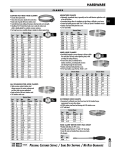
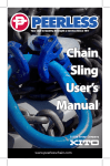
JEANNETTE
www.peerlesschain.com
www.chainusa.com
The One Stop Source for Everything Custom.
Peerless-ACCO is the only domestic chain manufacturer to have it’s own industrial sling center and custom
lifting device facility such as Jeannette. Over 20 skilled
craftsmen are employed at this facility, just 30 minutes
southeast of Pittsburgh. Jeannette not only manufacturers
and repairs welded slings (up to and including 2” chain)
and Kuplex mechanical slings, but also utilizes three
full-time blacksmiths to manufacture custom hooks,
slings and virtually any type of below-the-hook
overhead lifting device. Jeannette has a state-of-the-art
CAD system for use in designing an endless array of
special overhead lifting devices. The alloy steel welding
capabilities for master links and magnet chain assemblies are unlimited.
Jeannette uses the latest technologies, including
automated flash welders and trimmers. All of our slings
are heat treated in our sophisticated batch heat furnace
(most sling repair centers use single link heat treating
only) which ensures the entire sling has been consistently hardened to Peerless-ACCO specifications.
Capabilities
Jeannette’s capabilities extend beyond just production
of Custom Lifting Devices as we offer the following
Services and Support Materials as well.
Inspection: Every master link, chain link and hook is
checked for excess wear, nicks, gouges, deformation
and stretch. Components needing replacement are
marked and sent to the appropriate department for
repair. Each chain sling goes through eight or more
inspections before it is returned to you.
Proof Testing to 1,200,000 lbs: The complete chain
sling assembly is placed on hydraulic proof testing equipment. Here a load is gradually applied under direct
tension, over the chain sling’s full length until the proof
load, in pounds, is reached. After proof testing, the sling is
again thoroughly inspected.
Recertifying: Each chain that has been reconditioned
at Jeannette is restored to its original condition and
recertified. The metal tag that identifies each chain sling is
restamped with the sling’s rated working load limit, chain
size, reach and grade. In short order, the chain sling is
returned to you complete with a signed test certificate
attesting that the sling has been proof tested and meets
its original standards.
Chain Sling Inspection: Jeannette employs one
full-time employee who works throughout the country,
keeping end users in compliance with OSHA regulations
and offering assistance in solving their overhead lifting
problems.
Safety Seminars: Our Peerless-ACCO District Managers
are able to provide end users support by conducting safety
seminars and application analysis. From a 30 minute
Power Point to a 3-hour comprehensive safety
seminar...we have you covered.
Support Materials:
• Riggers Manual
• Working Load Limit Wall Charts
• Jeannette Background on
VHS & DVD
• Chain Gauges
• OSHA 1910.184 - specific
portion pertaining to
overhead lifting
• Engineering & Design
Assistance Available
Repairing: The repair section removes worn, damaged, stretched or deformed chain sling components
and replaces them. All repaired components are
replaced with the same high quality material and
specifications as the original.
Heat Treating: The chain sling is again inspected
after all repairs are made and before it is sent on to
heat treating. Carefully controlled heating, quenching
and tempering produces slings having the same high
tensile strength as the original.
1/2 x 2 1/2 x 5
Master Link
26
3
8 3/8
1/2
1/8 x 45º
(80TH Sides)
1ø Thru Holes
(2 Places)
5 15/16
3/8
1 1/8
16 1/8
R1/2
TYP
1/2
(6 Places)
Chan
1/2
50
3/8
ø4
3/8 - 16 X 2 UNC
( 2 REQ’D )
3
1
R5/16
TYP
21 3/4
13
1 1/2
2
3/4
ø3
1/8 X 45º
( BOTH 3
3/4 Grab Hook
(2 Req’d)
18 1/8
Weld
3 7/16
3
3 3/4
4 3/4
4 9/16
Do not exceed Working Load Limits (WLL)!
WARNING See the “Cautions and Warnings” section before using these products. Pages 13-15.
Table of Contents
Welded Chain Slings
Peerless-ACCO Alloy Chain . . . . . . . . . . . . . . . . . . . . . . . . . . . 4
Large Diameter Alloy Chain . . . . . . . . . . . . . . . . . . . . . . . . . . 5
General Chain Sling Information . . . . . . . . . . . . . . . . . . . 6 - 7
Magnet Chains . . . . . . . . . . . . . . . . . . . . . . . . . . . . . . . . . . . . . . . 8
Accoloy Plate Hooks & S-Hooks . . . . . . . . . . . . . . . . . . . . . . . . . 9
Custom Lifting Device Design Criteria . . . . . . . . . . . . . . . 10 - 12
Cautions & Warnings . . . . . . . . . . . . . . . . . . . . . . . . . . . . . 13 - 15
JEANNETTE a plant dedicated to
custom lifting applications
Products Available:
‘S’ Hooks
‘J’ Hooks
‘C’ Hooks
‘L’ Hooks
Mold Hooks
Core Hooks
Die Hooks
Lifting Slab Shackles
Box Hooks
Master Links
OEM Assemblies
Normalized Chain Slings
Door Lifting Chains
‘D’ Link Rings
Grab Links
Brake Chains
Pear Shaped Links
Magnet Bails
Winch Line Tail Chains
(with 1008 & 1018 Links)
Crack Links
Plate Hooks
Lifting Tongs
Pallet Lifting Assemblies
Die Pins
Slab Lifting Chains
Stirrup Hooks
R3 5/16
3 3/16
R2 15/16
Identification Tag
2
Master Ring
5/8 x 5
3
5/8 SHACKLE
63
R5/16
Connector
3/8 x 1 1/2 x 2 3/8
6 Places
3/8 - 16 x 1
(2 R/8)
6
R 1/2
R 1/2
4 3/4 TYP
ø7/8 Dia Pass
Hole O Places
R3/4
1 1/4ø
35
ø5/8 Pass Hole
1/16 x 45º Chan
On 80th SOCS
2 TYP
1/2 Accoloy Chain
9 Links Each Leg
5 5/8
1
50
ø13/16
1/2 x 3
Special Ring
R 1/4
#81 Sling Hook
2 Place
27
3
R2 7/8
2 3/4
R3/4
4
2 1/2
Do not exceed Working
Load Limits (WLL)!
WARNING See the “Cautions and Warnings” section before using these products. Pages 13-15.
1 1/4 RLF
3
Peerless-ACCO
Grade 80 & 100 Alloy Chain
Phone: 800-395-2445 • Fax: 800-997-3192
Welded Alloy Chain Slings are fabricated at our Jeannette facility to meet your specific lifting needs. Every welded chain sling is registered and documented for inspection should the chain sling require repair. One of the major components of our chain slings is the
Peerless-ACCO alloy chain. Welded Alloy Chain Slings are available with special attachments such as Plate Hooks, “J”– Hooks’ Lifting
Tongs, Shackles, Spreader Bars and more.
Peerless-ACCO alloy chain is rugged, versatile, high-strength, low-weight chain manufactured from special analysis alloy steel. It is
quenched and tempered before proof testing and the ultimate tensile strength is over twice that of ordinary steel chain. Tensile
strength following heat treatment meets or exceeds all existing OSHA, Government, NACM and ASTM specification requirements.
Specifications: Grade 80 & 100 Alloy Chain-NACM
Size
Working**
Load Limit
Nominal
Material Dia.
Grade 80 Grade 100 Grade 80 Grade 100
P8A(mm)
PA10 (in.) P8A & PA8* PA10 (lbs.)
& PA8(in.)*
(lbs.)
7mm
9/32”
3,500
4,300
8mm
5/16”
4,500
5,700
10mm
3/8”
7,100
8,800
13mm
1/2”
12,000
15,000
16mm
5/8”
18,100
22,600
3/4”
28,300
7/8”
34,200
1”
47,700
1-1/4”
72,300
Grade 80
P8A &
PA8 (in.)*
0.274
0.311
0.392
0.510
0.630
0.781
0.906
1.032
1.250
Grade 100
PA10 (in.)
0.279
0.342
0.404
0.529
0.625
Nominal
Inside Length
Grade 80 Grade 100
P8A &
PA10 (in.)
PA8 (in.)*
0.827
0.870
0.945
1.010
1.182
1.226
1.535
1.570
1.890
1.930
2.420
2.660
2.900
3.500
Minimum
Inside Width
Max
Weight
Grade 80 Grade 100
P8A &
PA10 (in.)
PA8 (in.)*
0.405
0.480
0.560
0.750
0.865
1.140
1.260
1.420
1.750
Grade 80 Grade 100
P8A & PA8
PA10
(lbs/100ft)* (lbs/100ft)
71.2
77.0
91.4
112.0
147.4
152.0
247.8
278.7
362.3
374.0
574.5
766.6
1010.0
1550.0
*Grade 80 alloy chain sizes up to and including 5/8” are stamped “P8A” and sizes 3/4” and above are stamped “PA8”. **Caution: Do not exceed Working Load
Limits (WLL)! Peerless Chain does not accept any liability for damages which may result from chain used in excess of working load limits.
Grade 80
Embossed
“PA8”
or “P8A”*
Full & Half Drums - Grade 80 & 100
Size
9/32”
5/16”
3/8”
1/2”
5/8”
3/4”
7/8”
1”
1-1/4”
Ft. Per
Drum
400
800
250
500
250
500
150
300
200
100
100
50
66
Drum
Size
Half
Full
Half
Full
Half
Full
Half
Full
Full
Full
Full
Full
Full
P8A & PA8
Grade 80
5050224
5050223
5050324
5050323
5050424
5050423
5050624
5050623
5050823
5050923
5051023
5051123
5051223
PA10
Grade 100
5510224
5510223
5510324
5510323
5510424
5510423
5510624
5510623
5510823
Grade 100
Embossed
“PA10”
4
Do not exceed Working Load Limits (WLL)!
WARNING See the “Cautions and Warnings” section before using these products. Pages 13-15.
Larger Diameter Alloy Chain
Phone: 800-395-2445 • Fax: 800-997-3192
Peerless-ACCO Now Brings You the Largest
Selection of Alloy Chain Ever
Now, from the leader in small to medium diameter alloy chain, comes our
newest, and biggest addition to the
family; 1–1/2”, 1–3/4” and 2” alloy chain
for overhead lifting. When we developed
our revolutionary 8 step manufacturing
process, we didn’t make any compromises, our goal was to give you the best
quality large diameter chain on the
market today. That’s why we’ve incorporated technology advances such as flash
welding - the best and most consistent
way to weld chain today - But it doesn’t
stop there, great chain is a function of
design as well. You’ll find the strength
enhancing features of triple alloy with
nickel, chromium, molybdenum and links
with a single weld.
When you consider all of these
enhancements, plus the assurance of
proof testing and certification, you’ll
realize that the large diameter alloy chain
is tough enough to handle any
lifting application.
Steel rods fired
in furnace
Jeannette’s furnace
is capable of
heating 2 inch
diameter steel in
about 15 minutes,
much faster then
conventional
furnaces, to ensure
quick turnaround
times for your
order
Rods are bent to
form chain links
Skilled craftsmen
bend rods into
precise shapes.
Each link is made
from one continuous piece of
metal, a key factor
in making a
stronger chain
1–1/2, 1–3/4 and 2” Diameter Chains
Large diameter chain with impressive lifting
ranges of 100,000 to 454,600 lbs. (3 and 4
leg slings). It can be used for virtually any
heavy lifting application. We can also add
custom lifting components designed and
built to your specifications at Jeannette.
Single Flash Weld
One of the most important steps in the
manufacturing process. That’s why each link is
individually welded with the best welding
technology available today - flash welding.
Jeannette’s new large diameter chains also
feature a single weld for maximum strength
and durability.
4 to 1 Safety Factor
Behind every Peerless-ACCO product is an
unparallel commitment to Safety. Each
chain is designed with a 4:1 safety
factor, before it is shipped to
you, it is proof tested and
certified by PeerlessACCO technicians.
Peerless-ACCO’s Revolutionary 8 Step
Manufacturing Process Leaves No Room for Error.
Single flash weld
A single flash
weld on each link
produces the
finest type of weld
in the industry. It
actually forces out
the impurities in
the metal while
making a weld.
Trimming the
Weld
This removes all
excess materials left
behind from the
welding process.
It gives you a
smooth finish link
with added safety
features by limiting
obstructions.
Heat Treating
Chain links are
heated to high
temperature, then
quenched to
strengthen the
properties of the
metal, which give
you a stronger
chain
Do not exceed Working Load Limits (WLL)!
Wheelabrator
After heat treating, the scale is
removed in the
wheelabrator,
which tumbles the
chain to a uniform, clean finish.
Proof Testing
After the chain is
fabricated, Jeannette
technicians proof
test the chain to
twice the recommended work load
so you can feel
confident when
using it in the field
Certification
After proof testing
each chain is
tagged with the
recommended
working load limit,
date, serial number, and reach. We
follow standards
established by
NACM and OSHA
WARNING See the “Cautions and Warnings” section before using these products. Pages 13-15.
5
Welded Alloy Chain Slings
Phone: 800-395-2445 • Fax: 800-997-3192
General Information
Work Load Limits
This table gives the working load limits of Grade 80 & Grade 100 Alloy chain in one, two, three and four leg styles. Use this
table as a guide to determine which chain sizes and leg styles are best for your requirements. Using the maximum load (or
loads) you will lift, and the angle of lift required – work to the left across this table to determine proper chain size for your sling.
Working load limit of the chain and components is established as pounds applied at the indicated degrees from horizontal.
Working Load Limits Specifications
Single Leg
Sling
Double Leg Sling
60°
45°
Triple and Quad Leg Sling
30°
60°
45°
30°
90°
Size
Grade 80
9/32”
3/8”
1/2”
5/8”
3/4”
7/8”
1”
1-1/4”
1-1/2”*
1-3/4”*
2”*
Grade 100
9/32”
3/8”
1/2”
5/8”
3,500
7,100
12,000
18,100
28,300
34,200
47,400
72,300
100,000
131,250
175,000
6,100
12,300
20,800
31,300
49,000
59,200
82,600
125,200
173,200
227,300
303,100
4,900
10,000
17,000
25,600
40,000
48,400
67,400
102,200
141,400
185,600
247,500
3,500
7,100
12,000
18,100
28,300
34,200
47,700
72,300
100,000
131,250
175,000
9,100
18,400
31,200
47,000
73,500
88,900
123,900
187,800
259,800
341,000
454,600
7,400
15,100
25,500
38,400
60,000
72,500
101,200
153,400
212,100
278,400
371,200
5,200
10,600
18,000
27,100
42,200
51,300
71,500
108,400
150,000
196,900
262,500
4,300
8,800
15,000
22,600
7,500
15,200
26,000
39,100
6,100
12,400
21,200
32,000
4,300
8,800
15,000
22,600
11,200
22,800
39,000
58,700
9,100
18,600
31,800
47,900
6,450
13,200
22,500
33,900
*Large diameter chain manufactured at our Jeannette facility.
Peerless ACCO combine to offer a broad range of quality ALLOY FORGING options.
“KUPLEX II” and “Accoloy” are premium domestic forgings available in Grade 80 and 100 with sizes through 1-1/4”.
The Kuplex II forgings provide a simple pin and clevis attachment for convenient assembly while the Accoloy forgings provide
a more conventional eye type attachment. All Kuplex II and Accoloy forgings are manufactured to rigid quality standards and
are compatible with all Peerless-ACCO alloy chains. Provided in a self-colored finish.
“Peer-Alloy” and “V10” are European forgings available in Grade 80 and 100 in sizes through 1-1/4” with both
clevis and eye styles.
“Peer-Lift” Grade 80 forgings are available in sizes through 5/8” in clevis or eye styles.
See our Peerless-ACCO Industrial Catalog for more information:
Mechanical Slings can be constructed using any of the Peerless and ACCO forgings. All forgings are compatible with
Peerless-ACCO alloy chains and component certs are provided with each attachment plus blank I.D. tags are readily available.
6
Do not exceed Working Load Limits (WLL)!
WARNING See the “Cautions and Warnings” section before using these products. Pages 13-15.
Welded Alloy Chain Slings
Phone: 800-395-2445 • Fax: 800-997-3192
Types of Chain Slings
Welded
Mechanical
DOS shown
SOS Shown
Attachments
Type
One End
Opposite End
Single Chain Slings
SOS
Oblong Link
SOG
Oblong Link
SGS
Grab Hook
SGG
Grab Hook
SSS
Sling Hook
SOF
Oblong Link
SOO
Oblong Link
Sling Hook
Grab Hook
Sling Hook
Grab Hook
Sling Hook
Foundry Hook
Oblong Link
Double Chain Slings
DOS
Oblong Link
DOG
Oblong Link
DOF
Oblong Link
Sling Hooks
Grab Hooks
Foundry Hooks
Triple Chain Slings
TOS
Oblong Link
TOG
Oblong Link
TOF
Oblong Link
Sling Hooks
Grab Hooks
Foundry Hooks
Quadruple Chain Slings
QOS
Oblong Link
QOG
Oblong Link
QOF
Oblong Link
Sling Hooks
Grab Hooks
Foundry Hooks
How to Order
The following information should be given on orders or inquires for chain slings.
1. SIZE: This is specified by the size of the material from which the chain is made, determined by working load limit required.
2. REACH: This is the length, including attachments, measured from bearing point to bearing point.
3. TYPE: Select and specify proper type of sling from list shown. Examples: S = single; O = oblong link; S = sling hook
4. ATTACHMENTS: Unless otherwise specified standard master links as given herein will be used. When other than
standard master links or hooks are required, we should be given a complete description or a drawing of the requested substitute.
When hot galvanizing is specified our recommended working load limits must be reduced.
Please contact us with all such inquires.
SOO
SOS or SOSH SOG
QOS
SOF
Adjustable Single
DOS
Adjustable Double
Do not exceed Working Load Limits (WLL)!
DOG
DOF
Single Endless
Basket
TOS
Double Endless
Basket
WARNING See the “Cautions and Warnings” section before using these products. Pages 13-15.
7
Magnet Chains
Phone: 800-395-2445 • Fax: 800-997-3192
Accoloy® Steady-Lift Magnet Chains
Eliminates Costly Down Time With Lift After Lift, Built-In Dependability.
• Ease of Use - Designed so bail stands up while chain rests on floor, there is no wrestling
with the bail for hook-up.
• Balanced Loading - Three point suspension offers superior stability.
• Wearability - Engineered and built for increased service life, with heat treated bail, pins,
alloy chain and end links.
• Less Down Time - Easy inspection, replaceable pins, legs and bail mean more time on
the job and fewer off-site repairs.
(3 point suspension)
A
C
B
D
Replacement Parts
Magnet Chain Size
1”
1-1/4”
Pin
537101630
537102030
Leg
537101620
537102020
Yoke
537101610
537102010
F
E
Specifications - Dimensions in Inches
Size
Stock
of
WLL No. of
No.
Chain
Lbs.
Links
537101600 1” 100,000 5
537102000 1-1/4” 150,000 7
A
B
Mtl. Yoke
Dia. Wth.
2-1/4” 7”
2-1/2” 7”
C
Yoke
Lgh.
12”
12”
D
E
F
G
Comp. Yoke Chain
Pin
Magnet
Vert. End Link End Link End Link Assy. Wt.
Leg.
Wt. Diameter
Reach Wth.
Lgh.
Dia.
Wt. Lbs. Lbs. Wt. Lbs. Lbs. Ea.
In.
3’-7”
3”
7”
1-1/4”
235 125
31
5.0
up to 60
4’-7”
3”
7”
1-1/2”
375 180
60
5.5 60 and over
Accoloy® Standard Magnet Chains
Specifications
Stock
No.
537301000
537301200
537301400
537301600
537302000
Chain
Size
In.
mm
5/8
16
3/4
20
7/8
22
1
26
1-1/4
32
WLL Lbs.
at 60º
47,000
73,500
88,900
123,900
187,800
A
Dia.
Mtl.
In.
1-3/4
2
2-1/4
2-1/4
2-1/2
Master Link
B
C
Inside Inside
Width Length
In.
In.
6
10
6
10
6-1/2 11-1/2
6-1/2 11-1/2
6-1/2 12-3/4
Oblong Link
A
B
C
Dia.
Inside Inside
Mtl. Width Length
In.
In.
In.
7/8
2-1/4
5-1/2
1
2-1/2
6
1
2-1/2
6
1-1/4
3
7
1-1/2
3
7
5 Link
Reach
In.
30-5/8
34
36-7/8
40
45-1/2
Magnet
Diameter
In.
up to 40
up to 45
up to 48
up to 60
60 and over
Call for 7, 9, and 11 link reaches. Special order reaches available.
Standard “D”
Master Link
Reach
with 5
Links
A
B
4-Po t
Suspenin
sion
also a
C
vailable
Main
Chain
Handles Optional
C
8
A
Pear Shaped Master Link
Optional
Do not exceed Working Load Limits (WLL)!
WARNING See the “Cautions and Warnings” section before using these products. Pages 13-15.
Custom Lifting Devices
Phone: 800-395-2445 • Fax: 800-997-3192
Accoloy® Plate Hooks
Accoloy Plate Hooks are designed for the most popular chain sizes - 9/32”, 3/8”, 1/2”, 5/8” and 7/8”. They are proof tested to
the same values as the corresponding chain - therefore, the same working load limit applies.
Fabricated from alloy steel, Plate Hooks can be furnished on Welded Chain Slings as well as with various chain assemblies.
Accoloy Plate Hooks are intended for use in handling plates, flats and structurals.
Specifications
WLL
Lbs.
3,500
7,100
12,000
18,100
28,300
34,200
Wt.
Each
Lbs.
2.4
4.6
10.6
20.7
36.7
52.6
Dimensions-Inches
L
M
2
2
2-5/8 3
3-1/2 4
4-3/8 5
5-3/16 6
6
7
N
O
P
T
U
1-1/2 13/16
7/8
3/4
2
1-7/8 1-1/16 1-1/8 3/4 2-1/4
2-1/2 1-3/8 1-1/2
1
3
3-1/8 1-3/4 1-7/8 1-1/4 3-3/4
3-3/4 2-1/8 2-1/2 1-1/2 4-1/2
4-1/2 2-7/16 2-5/8 1-3/4 5-1/4
T
O
Size of
Chain
In. mm
9/32 7
3/8 10
1/2 13
5/8 16
3/4 20
7/8 22
U
N
Stock
Number
593400400
593400600
593400800
593401000
593401200
593401400
P
Customour
DesignPY
te
Own lka
o
Ho 12
M
see page
L
Accoloy® S-Hooks
Alloy “S” Hooks for use on overhead parts painting and processing conveyor systems and many other material handling requirements.
Working Load Limit and “A”, indicating alloy steel, are stamped on each hook. Custom sizes are available upon request.
Specifications
Stock
Number
593300600
593300800
593301000
593301200
593301400
C
Size
Inches
3/8
1/2
5/8
3/4
7/8
WLL
Lbs.
430
770
1,200
1,700
2,300
Wt. Each
Lbs.
.28
.63
1.3
2.1
3.4
D
3/8”
1/2”
5/8”
3/4”
7/8”
Dimensions
B
T
4-1/8”
1-1/8”
5-1/2”
1-1/2”
7”
1-7/8”
8-1/4”
2-1/4”
9-5/8”
2-5/8”
Do not exceed Working Load Limits (WLL)!
C
1-1/8”
1-1/2”
1-7/8”
2-1/4”
2-5/8”
D
T
B
T
C
WARNING See the “Cautions and Warnings” section before using these products. Pages 13-15.
9
Custom Master Links
Phone: 800-395-2445 • Fax: 800-997-3192
Built to Specification: Small to Oversized Links
Forged and welded from
material up to 6 inches in
diameter. Magnet chain
D-link and oblong link
(shown), pear shape, rings
and other shapes available.
Forming Red Hot D
Link from 2” Material
for Magnet Chain
Master Link.
Custom Link Capabilities
• 6” diameter Largest Master link
• Oblong Master Links
B
• Magnet Bails (D-Links)
• Pear Shaped Links
• Grab Links
• Rings
OBLONG
A
C
A
B
C
CAP.
RING
_________
_________
_________
_________
A _________
B _________
CAP. _________
A
B
F
G
D
B
PEAR
D
E
F
G
CAP.
_________
_________
_________
_________
_________
A
E
10
SUB - ASSEMBLY
C
D
F
A
B
C
D
E
F
CAP.
_________
_________
_________
_________
_________
_________
_________
E
Do not exceed Working Load Limits (WLL)!
WARNING See the “Cautions and Warnings” section before using these products. Pages 13-15.
Custom Lifting Devices
Phone: 800-395-2445 • Fax: 800-997-3192
J Hooks
B
B
C
A
A
B
C
D
E
F
G
Style
Capacity
B
F
C
A
A
C
G
E
E
E
D
D
D
A
B
C
______________
______________
______________
______________
______________
______________
______________
______________
______________
Shackle
D
G (Dia thru)
E
H
W
G DIA THRU
W2
Capacity
W2
D
R
W
Grab Link
______________
______________
______________
______________
______________
______________
______________
E
Stirrup Hook
B
R1
DIA
A
A
ANGLE 1
D
D
B
C
ANGLE 2
A
B
C
D
Angle 1
Angle 2
Dia
R1
W
Style
Capacity
______________
______________
______________
______________
______________
______________
______________
______________
______________
______________
______________
W
A
C
A
B
C
D
Capacity
B
R2
C
R2
______________
______________
______________
______________
______________
W
Do not exceed Working Load Limits (WLL)!
W
D
R2
W
R2
OPTIONAL
CROSSBAR
W
WARNING See the “Cautions and Warnings” section before using these products. Pages 13-15.
11
Custom Lifting Devices
Phone: 800-395-2445 • Fax: 800-997-3192
Hook & Ring Assemblies:
A
Style (circle one A B C)
B
C
A
B
C
D
E
F
G
H
I
Capacity
S-Hooks
Style (circle one A B C)
A
B
C
D
E
F
R
Capacity
A
B
Plate Hook
______________
______________
______________
______________
______________
______________
______________
______________
C
Spreader Beams
A
B
C
D
E
F
G
Angle 1
Angle 2
Angle 3
Capacity
12
______________
______________
______________
______________
______________
______________
______________
______________
______________
______________
______________
______________
______________
______________
______________
______________
______________
______________
______________
______________
______________
Do not exceed Working Load Limits (WLL)!
Horizontal Spacing ______________
Vertical Reach ______________
Capacity ______________
WARNING See the “Cautions and Warnings” section before using these products. Pages 13-15.
Cautions & Warnings
Phone: 800-395-2445 • Fax: 800-997-3192
General Safety Guidelines
Peerless Industrial Group, as a manufacturer of chain,
can only control the specifications of our chain products in
accordance with industry and governmental standards
for chain manufacturing. It would be impossible for any
warning to contain all of the possible misapplications associated with the use of Peerless Industrial Group products.
Our warnings are intended to identify only those risks
which are most common. The responsibility and understanding of the proper safe use and application of the
products in our catalog, ultimately rest with the end user.
We are not responsible for the end user’s assembly in
which our chain may be used. Failure of the product can
occur due to misapplication, abuse, intentional alteration
or improper maintenance. Product failure can result in
property damage, personal injury or death.
Working Load Limit (WLL)
The “Working Load Limit” (rated capacity) is the maximum
load that shall be applied in direct tension to an undamaged straight length of chain.
Proof Test
The “Proof Test” (manufacturing test force) is a term
designating the minimum tensile force which has been
applied to a chain under constantly increasing force in
direct tension during the manufacturing process. These
loads are manufacturing integrity tests and shall not be
used as criteria for service or design purposes.
Minimum Breaking Force
The “Minimum Breaking Force” is the minimum force at
which the chain during manufacture has been found by
testing to break when a constantly increasing force is
applied in direct tension. Breaking force values are not
guarantees that all chain segments will endure these
loads. This test is a manufacturer’s attribute acceptance
test and shall not be used as a criteria for service or
design purposes.
The Working Load Limits and the associated safety factor of each Peerless product may be affected by wear,
misuse, overloading, corrosion, deformation, intentional
alteration and other use conditions. Regular inspection
must be conducted to determine whether use can be
continued at the assigned Working Load Limit, a reduced
Working Load Limit or whether the product must be
withdrawn from service. The terms “Working Load Limit”,
“Proof Test” and “Minimum Breaking Force” contain no
implication of what load the chain will withstand if the
chain is used in such conditions of abuse and misuse.
Peerless Industrial Group accepts no liability for any such
abuse or misuse.
The Working Load Limit of a sling or assembly must not
exceed the lowest Working Load Limit of the components in the sling or assembly. Use only Peerless
Industrial Group approved parts as replacements when
servicing or repairing original Peerless Industrial Group
slings or assemblies.
USE ONLY GRADE 80 OR GRADE 100 ALLOY CHAIN
AND ATTACHMENTS FOR OVERHEAD LIFTING. Please
see page 6 for more information regarding alloy chain
Working Load Limits in relation to the angle of lift.
PEERLESS INDUSTRIAL GROUP PRODUCTS ARE INTENDED
TO BE USED AT OR BELOW THE MAXIMUM WORKING
LOAD LIMITS SPECIFIED IN CONSTANTLY INCREASING
FORCE APPLICATIONS UNDER DIRECT TENSION OR IN A
STRAIGHT LINE PULL.
SHOCK LOADING IS PROHIBITED AND SIDE LOADING
MUST BE AVOIDED, AS IT EXERTS ADDITIONAL DYNAMIC
FORCES OR LOADING WHICH THE PRODUCT IS NOT
DESIGNED TO ACCOMMODATE.
THE CONDITIONS INVOLVING USE IN CERTAIN ENVIRONMENTAL SITUATIONS SUCH AS UNUSUAL (HIGH OR
LOW) TEMPERATURE, CHEMICAL, ETC..., CAN CAUSE
CHANGES IN CHAIN PERFORMANCE.
All chains and attachments in this catalog are capable of
creating sparks unless otherwise noted.
Welding Peerless Industrial Group load support parts or
products can be hazardous. Knowledge of materials,
heat treatment and welding procedures are necessary for
proper welding.
CONSULT PEERLESS INDUSTRIAL GROUP FOR ADDITIONAL
INFORMATION OR QUESTIONS REGARDING THE USE
AND APPLICATION OF THE PRODUCTS COVERED IN THIS
CATALOG.
Do not exceed Working Load Limits (WLL)!
WARNING See the “Cautions and Warnings” section before using these products. Pages 13-15.
13
Cautions & Warnings
Temperature and Chain
Use of Grade 80 Chain Under
Heat Conditions
Use of Grade 100 Chain Under
Heat Conditions
Effect of Elevated Temperature on the
Working Load Limit of Grade 80 Alloy Chain.
Effect of Elevated Temperature on the
Working Load Limit of Grade 100 Alloy Chain.
Chains should not be used outside of the -40º F to 400º F
(-40º C to 204º C) temperature range without consulting
the chain manufacturer. The specific working load limit
reductions for Grade 80 chains used at and after exposure
to elevated temperatures have been established and are
shown below.
Chains should not be used outside of the -40º F to 400º F
(-40º C to 204º C) temperature range without consulting
the chain manufacturer. The specific working load limit
reductions for Grade 100 chains used at and after
exposure to elevated temperatures have been established
and are shown below.
Maximum
Temperature of
Chain
Reduction of
Working Load
Limit While At
Temperature
Reduction of
Working Load Limit
After Exposure to
Temperature
Maximum
Temperature of
Chain
Reduction of
Working Load
Limit While At
Temperature
Reduction of
Working Load Limit
After Exposure to
Temperature
Below 400º
400º
500º
600º
700º
800º
900º
1000º
Over 1000º
None
10%
15%
20%
30%
40%
50%
60%
* (see below)
None
None
None
5%
10%
15%
20%
25%
* (see below)
Below 400º
400º
500º
600º
700º
800º
900º
1000º
Over 1000º
None
15%
25%
30%
40%
50%
60%
70%
* (see below)
None
None
5%
15%
20%
25%
30%
35%
* (see below)
* OSHA 1910.184 requires all slings exposed to
temperatures over 1000º F to be removed from service.
* OSHA 1910.184 requires all slings exposed to
temperatures over 1000º F to be removed from service.
General Hook & Latch
Guidelines
Important Safety Information - Read & Follow
• Always inspect hook and latch before using.
• Never use a latch that is distorted or bent.
• Always make sure spring will force the latch
against the tip of the hook.
• Always make sure hook supports the load.
Do not point load hooks–load should bear
on the bowl of hook. The latch must never
support the load. (See Figure 1 & 2).
• Latches are intended to retain loose sling or
devices under slack conditions.
• Latches are not intended to be an
anti-fouling device.
Figure 1
If chain is worn to less than
the minimum allowable
thickness (T), remove the
chain from service.
T
Specifications
Size of Chain Material Diameter
RIGHT
Figure 2
WRONG
14
Table of Wear
Inches
9/32”
3/8”
1/2”
5/8”
3/4”
7/8”
1”
1-1/4”
mm
7mm
10mm
13mm
16mm
20mm
22mm
26mm
32mm
Do not exceed Working Load Limits (WLL)!
Grade 80
0.274
0.392
0.510
0.630
0.781
0.906
1.032
1.250
Grade 100
0.279
0.404
0.529
0.625
-----
Min Allowable
Thickness (T)
Grade 80
0.247
0.353
0.459
0.536
0.664
0.770
0.877
1.063
Grade 100
0.239
0.353
0.459
0.546
-----
WARNING See the “Cautions and Warnings” section before using these products. Pages 13-15.
Cautions & Warnings
Check #1 Inspections
Visually examine the sling
before each use. Look for
stretched, gouged, bent
or worn links and
components, including hooks,
with open throats, cracks or
distortion, if damaged,
remove from service.
Worn Links
Bent Links
Gouged Links
Stretched Links
Check #5 Sharp Edges
Protect chain with
padding when lifting sharp
edged loads.
Check #6 Abrupt
Movement
Lift and lower loads
smoothly. Do not jerk.
Check #2 - Balance
Know the load —
determine the weight,
center of gravity, angle
and lift and select the
proper size of sling.
Check #3 Overload
Never overload the sling —
check the working load limit
on the identification tag.
Always consider the effect of
Angle of Lift — the tension
on each leg of the sling is
increased as the angle of lift,
from horizontal, decreases.
Use the chart in this catalog
or in the Peerless-ACCO
Chain Sling User’s Manual for
this purpose.
Check #4 - Knots,
Twists & Kinks
Check #7 High
Temperatures
Do not expose alloy chain
or sling to temperatures
of 400°F or higher.
Check #8 Chain Care
Store slings properly on
an A-Frame and protect
chain slings from
corrosion during
storage.
Make sure chain is not twisted,
knotted or kinked before lifting
load. Slings should not be
shortened with knots, bolts or
other make-shift devices.
Do not exceed Working Load Limits (WLL)!
WARNING See the “Cautions and Warnings” section before using these products. Pages 13-15.
15
Distributed By:
Specifications are subject to change without notice.
© 2008 Peerless Industrial Group • 10/08 5M 27.15
JEANNETTE
401 Spring Valley Road
Jeannette, PA 15644
800-395-2445
Fax: 800-997-3192
CORPORATE OFFICE
1416 East Sanborn Street
P.O. Box 5349
Winona, MN 55987
www.peerlesschain.com