1
INDEX
CHAPTER 1- SUMMARY OF USER’S COMMANDS ................................ 3
CHAPTER 2 – ABOUT THE KEYPAD.......................................................... 4
RP208KCL (LCD KEYPAD) ................................................................................ 4
LED INDICATION AND KEYS .................................................................................. 5
FUNCTION AND OPERATION .................................................................................. 7
1. Setting/Changing and Deleting User’s Code ................................... 7
2. Setting Date and Time ......................................................................... 9
3. Displaying System Date and Time..................................................... 9
4. Setting Follow-me Number ................................................................. 9
5. Quick Arming ...................................................................................... 10
6. Code Arming ....................................................................................... 10
7. Bell Squawk on Arming ..................................................................... 10
8. Disarming ............................................................................................ 10
9. On/Off Audible kiss-off ........................................................................11
10. Duress Disarming .............................................................................11
11. Cutting off Sounder and Stop Auto-dialing ....................................11
12. Bypassing/ Un-bypassing a Zone .................................................. 12
13. Escape Key [ESC] ........................................................................... 12
14. Emergency Keys .............................................................................. 12
15. Entry and Exit Delays ...................................................................... 13
16. 24-Hour Zone ................................................................................... 13
17. Trouble Display ................................................................................. 13
18. Zone Features .................................................................................. 14
19. Get Events from Event Logger....................................................... 14
20. On/Off Door Chime .......................................................................... 15
CHAPTER 3 - INSTALLATION .................................................................... 16
BEFORE INSTALLATION ...................................................................................... 16
FAQ. OF INSTALLATION AND SOLUTION ............................................................... 16
THE MAIN BOARD ............................................................................................. 17
RP208CN User’s and Installer’s Manual
Page 1
INSTALL CONTROL PANEL AND KEYPAD ................................................................ 21
CONNECT THE TELEPHONE LINE ......................................................................... 21
CONNECT THE STANDBY BATTERY ...................................................................... 21
CONNECT TRANSFORMER .................................................................................. 21
CONNECT SIREN ............................................................................................... 21
CONNECT DETECTOR(S) .................................................................................... 22
CONNECT VOICE MODULE ................................................................................. 22
CONNECT WIRELESS MODULE ........................................................................... 23
PLEASE REFER TO RP208EW4 USER'S MANUAL FOR MORE
DETAILS. ......................................................................................................... 24
CHAPTER 4 - FUNCTION AND TECHNICAL DATA ............................... 26
MAIN FEATURES OF RP208KCL ....................................................................... 26
MAIN FEATURES OF RP208MB.......................................................................... 27
RESTORING FACTORY DEFAULTS ........................................................................ 30
PROGRAM EXPLAIN ........................................................................................... 30
CHECK LOCATION DATA ..................................................................................... 30
ENTRY/EXIT PROGRAM .................................................................................. 31
A PROGRAMMING TUTORIAL ............................................................................... 31
General System Parameters: Locations 00-07 .................................. 32
Installer Code:Location 08-10 ............................................................ 33
SYSTEM TIME: LOCATIONS 11-13 .................................................................... 33
INTRUSION ZONE TYPES AND ZONE SOUNDS:LOCATIONS 14-21.......................... 34
UTILITY OUTPUTS- EVENT AND RESULT:LOCATIONS22, DEFAULT 00 .................... 36
COMMUNICATION PARAMETERS:LOCATIONS26-29 ............................................. 39
DIGITAL COMMUNICATOR CONTROLS:LOCATIONS 26, DEFAULT 41....................... 39
CENTRAL STATION PROTOCOLS:LOCATION 27, DEFAULT: 00 ............................... 39
CS PROTOCOLS: LOCATION 28, DEFAULT: 03 ....................................................... 41
PERIODIC TEST TIME:LOCATION 31 .................................................................. 43
COMMUNICATOR REPORTING CODES:LOCATIONS 32-94 .................................... 43
REPORTING CODES FOR ALARM EVENTS: ......................................... 43
RP208CN CONTROL PANEL CONTACT ID REPORTING CODES ..... 47
RP208CN User’s and Installer’s Manual
Page 2
CHAPTER 1- SUMMARY of USER’S COMMANDS
The Summary of User’s Commands offers installers and users a quick and
convenient way to operate control panel. All can be done under the state of
disarm and so it doesn’t need to enter programming statue. For detailed
information, please go chapter 2.
Function
Quick arm
Arm by code
Stay Arm
Stay Arm by code
System disarm
Bypass disarm
Free from siren
Bypass/un-bypass zone
Quick bypass/un-bypass zone
Display trouble
Display time
Set/change main code
Set/change a user code
Set date
Set time
Auto arm time
Set follow-me phone no. 1
Set follow-me phone no. 2
Set follow-me phone no. 3
Set follow-me phone no. 4
On/off buzzer
On/off door chime
Audible kiss-off
Display memory
Test system
keypad panic alarm
keypad fire alarm
keypad special emergency
Escape
Trouble Table
Procedure
[ARM]
[ARM]+[master code]
[STAY]
[STAY]+[master code]
[user code]
[duress code]
[user code]
[*]+[1]+[user code]+[zone number]
[zone ]at least 2 seconds
[*]+[3]
[*]+[4]
[*]+[5]+[master code]+[0]+[new code]
[*]+[5]+master code]+[1-9]+[new code]
[*]+[6]+[1]+[master code]+[MM][DD][YY]
[*]+[6]+[2]+[master code]+[H][H][M][M]
[*]+[6]+[3]+[master code]+[H][H][M][M]
[*]+[7]+[1]+[master code]+[phone No. 1]+[#]
[*]+[7]+[2]+[master code]+[phone No. 2]+[#]
[*]+[7]+[3]+[master code]+[phone No. 3]+[#]
[*]+[7]+[4]+[master code]+[phone No. 4]+[#]
[*]+[8]+[master code]+[1]
[*]+[8]+[master code]+[2]
[*]+[8]+[master code]+[3]
[*]+[9]+[master code]+[enevt number]
[*]+[0]+[master code]
[1]+[2] at leadt 2 seconds
[4]+[5] at least 2 seconds
[7]+[8] at least 2 seconds
[ESC]
LCD
Battery Low
AC Power
No Clock
No Communication
No Siren
Trouble
The Backup Battery Power is low.
AC Power is lost.
Clock have not been set
The Communication is in trouble.
The Siren connection is in trouble.
RP208CN User’s and Installer’s Manual
Page 3
CHAPTER 2 – ABOUT THE KEYPAD
RP208KCL (LCD Keypad)
The RP208CN can support LCD Keypad. Each control panel can work with four
LCD Keypads at most.
Each keypad in your system reports its status by its LED (lighted) indicators and
LCD display. Through its keys, you can enter commands to Arm and Disarm the
system, bypass intrusion zones, report emergencies, stop the siren, checking the
trouble, programming the system and other handling.
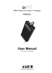
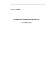
Fig.1 Layout of the RP208KCL
Keypad Instruction
1-Power
7- Tamper
2-LCD Display
8-Arm key-press
3-Arm
9-Stay key-press
4-Disarm
10-Buzzer
5-Bypass
11-Exit/Delete key-press
6-Fire
12-Digit and Function key-press
RP208CN User’s and Installer’s Manual
Page 4
LED Indication and Keys
1. Power LED
On--The system is operating properly from commercial (AC) power; its
backup battery is in good condition.
Off--The system is inoperative due to the lack of power (from both
commercial AC and backup battery).
Flash-- Indicates a trouble condition.
2. LCD Display
The LCD Display on RP208KCL indicate the status of each of the system,
including zones Triggered, Armed/Disarmed system, Trouble, Time and other
programming information. If there is only “ROISCOK” on the display, which
means all the zones are not triggered. When Z1, Z2, Z3, Z4, Z5, Z6, Z7 or Z8
is/are displayed on the display, which means the zone is triggered:
Statue
Explanation
System Disarmed
System Armed
ROISCOK
All the zones are secured and working normally
Z1
Z2
…
Z8
Zone 1 was triggered
Zone 2 was triggered
…
Zone 8 was triggered
An alarm has occurred on Zone1
An alarm has occurred on Zone2
…
An alarm has occurred on Zone8
3. ARM LED
The ARM LED indicates whether or not the system is armed. In armed
condition, the ARM LED is on, in case of any violations, there will be an alarm.
The ARM LED is flashing, which means burglar, fire or emergency alarm once
has/have occurred in the corresponding zone(s). The ARM LED is off when the
system is disarmed.
Statue
EXPLANATION
When the system is armed, in case of any emergency, an
alarm will occur. The Siren will sound, and system will also
On
dial the follow-me numbers and send alarm report to alarm
center.
Off
The system is disarmed.
Flashing Burglar, fire and/or has/have once occurred.
RP208CN User’s and Installer’s Manual
Page 5
4. READY LED
The Ready LED indicates whether the system is working normally or not, and
also indicates whether system can be armed or not. When disarm, the LED will
be on; when arm, the LED will be off.
STATUS
EXPLANATION
All the zones are working normally, and then the system can
On
be armed now.
1. Someone is moving in the zone.
Off
2. The system is armed.
Flashing The system is under the programming status
5. BYPASS LED
The BYPASS LED Indicate that one or more of the system’s intrusion zones
have been bypassed; for more information on bypassing.
6. FIRE LED
When fired the LED flashing rapidly.
7. TAMPER LED
When the detector(s) or the keypad is /are tampered or destroyed, a Tamper
Code report will be sent and the LED will be flashing.
8. System Arming [ARM]
When [ARM] key is depressed, all the zones are armed.
9. Stay Home Arming [STAY]
Home Arming (or Stay Arming) allows individuals to remain inside and move
about the premises even after the system is armed. Home Arming arms the
perimeter detectors (e.g. door and windows), while leaving interior detectors
(e.g. motion detectors) disarmed (bypassed). When [STAY] key is depressed,
the interior zones will not be armed.
10. Exit/Delete [ESC]
Key [ESC] is suitable for correction system operation
RP208CN User’s and Installer’s Manual
Page 6
11. Digit Keys
When programming, key in 0-9 digits.
12. Function Key [*] [#]
When programming, key [*] to enter function mode; and [#] for confirmation.
Function and Operation
Keys and Functions
The Keys can support the following functions:
1. Enter digit(s) for Arming, Disarming, Panic Alarm, Programming etc.
2. Enter user’s function mode.
3. Key [ARM] is for Quick Arming and Code Arming. By pressing it, the
system will be fully armed.
4. Key [STAY] is for Quick Stay Arming and Code Stay Arming. By pressing it
to arm, only part of the zone is armed. Each zone can be set as interior
zone or external zone. When use [STAY] for arming, the external zone is
armed while leaves the interior zone disarmed.
5. Under the disarmed status, press [*] to enter user’s function mode.
Reference to CHAPTER 1- SUMMARY of USER’S COMMANDS
1. Setting/Changing and Deleting User’s Code
The default Master Code of RP208CN is 1-2-3-4. Unless your alarm company
has already changed it to suit your preference, it’s best to modify this code to
one which is unique and personalized. RP208CN can set 10 of Codes, one is
Master Code and another 9 are User’s Codes. To change the Master Code,
and /or to set up User Coeds, follow the steps. Make sure the system is
disarmed when setting the code. The User’s Codes are only for Arming and
Disarming the system
Functions of the Master Code:
Adding, changing and deleting User’s Code
Setting Time Clock
Operating and testing
Setting the follow-me numbers
RP208CN User’s and Installer’s Manual
Page 7
Setting / Changing the master Codes
Step
1
2
3
4
5
Operation
The system must be disarmed (the ARMED LED will be
OFF). Enter the User Functions Mode [*][5]
Enter the current 4-digit Master Code:
For example, Press [ 1][2 ][3 ][4 ]
Press [0]
Enter the new 4-digit code selected will emit a one-second
confirming tone. The selected User Code is now in effect.
For example, press[5 ][6][7 ][ 8]
If successful, the keypad will emit a confirming tone “Beep
-”. The selected User Code is now in effect.
Setting/Changing 1-9 User Codes
At times, it may be desirable to completely delete a User Code. Note that it is
impossible to delete the Master Code (although it can be changed).
Step
1
2
3
Operation
The system must be disarmed. Enter the User Functions Mode
[*] and choose Codes [5]
Press [*][5]
Enter the current 4-digit Master Code:
For example, [5 ][6 ][7 ][8 ]
To set/delete the User Code 1, press [1]
To set/delete the User Code 2, press [2]
To set/delete the User Code 3, press [3]
…
The other Codes can be set/deleted in the same way.
4
Enter the new User Code:
For example, [3][3][5][5]
5
If successful, the keypad will emit a confirming tone “Beep-”.
The selected User Code is now in effect.
Deleting User’s Codes
At times, it may be desirable to completely delete a User Code. Note that it is
impossible to delete the Master Code (although it can be changed).
Step
Operation
1
The system must be disarmed. Enter the User Functions Mode
[*] and choose Codes [5], Press [*][5]
2
Enter the current 4-digit Master Code: [5 ][ 6][7 ][8 ]
RP208CN User’s and Installer’s Manual
Page 8
3
To delete the User Code1, press [1]
To delete the User Code1, press [2]
To delete the User Code1, press [3]
…
The other Codes can be deleted in the same way.
4
Enter the [#]
5
If successful, the keypad will emit a one-second confirming
tone. The selected User Code is now deleted.
2. Setting Date and Time
Set date: [*]+[6]+[1]+[MASTER CODE]+[MM][DD][YY]
Month, Date and Year should all be two digits.
Set time: [*]+[6]+[2]+[MASTER CODE]+[HH][MM]
Use a 24-Hour format. Hour and Minute should be two digits.
For example, if you want to enter 16:28, August 18, 2006, operate as :
[*]+[6]+[1]+[MASTER CODE]+[08][18][06]
[*]+[6]+[2]+[MASTER CODE]+[16] [28]
3. Displaying System Date and Time
Press [*]+[4] to check the system time on LCD keypad. And the format
should be:
MM/DD/YY Hour :Minute
4. Setting Follow-me Number
In case of an alarm event, a phone call can be made to one or more
predefined phone number. There are three different tone types that represent
burglary, fire and special emergency alarms.
The Follow-Me function can support four phone numbers for each system.
Make sure the numbers are all correct; then enter [#]. Operate as:
Set Follow-Me Phone NO.1: [*]+[7]+[1]+[MASTER CODE]+Phone NO.1+[#]
Set Follow-Me Phone NO.2: [*]+[7]+[2]+[MASTER CODE]+Phone NO.2+[#]
Set Follow-Me Phone NO.3: [*]+[7]+[2]+[MASTER CODE]+Phone NO.3+[#]
Set Follow-Me Phone NO.4: [*]+[7]+[2]+[MASTER CODE]+Phone NO.4+[#]
RP208CN User’s and Installer’s Manual
Page 9
5. Quick Arming
RP208CN can be divided as interior zone and external zone by programming.
Zone 7 and Zone 8 are defaulted as interior zone.
Press [ARM], and all the zones will be armed.
Press [STAY], then external zone will all be armed while leaves the interior
zones disarmed.
Step
1
2
3
4
Operation
Before you arm your system, all of its zones must either be
secured or bypassed .The keypad’s READY LED, if lit,
indicates that all zones are secured. If the READY LED is not
lit, one or more unsecured zone(s) will be display on the LCD.
Quick Arming and Code Arming:
Quick Armed:Armed the system just by press [ARM].
Quick Stay Armed:Stay Armed just press [STAY].
Three short Beep from the keypad when there are some errors
in entering. Then re-operate it.
When arming the system, there will be one confirmation sound,
which means the exit delay begin now. Then leave here before
the exit delay time is over to avoid false alarm. The exit delay
time is defaulted as 30 seconds.
6. Code Arming
Your RP208CN offers two methods of arming, Quick Arming and Code Arming.
It’s defaulted as quick arm. If the user requires code arm, it should be set when
programming in advance.
When RP208CN is set as code arm, it can not support [ARM] and [STAY] for
quick arming. And it should be operated as: [ARM] + [Master Code], or [STAY]
+ [Master Code] to arm or stay arm.
7. Bell Squawk on Arming
If selected, Bell Squawk on Arming will produce a brief confirmation "chirp"
from the system's external sounder(s) once the system is armed and the Exit
Delay expires. To cancel it, refers to Location 30 in Chapter 5.
8. Disarming
RP208CN can set 10 Codes (4 digits), one Master Code and 9 User Codes. In
arming status, simply enter any code of the 10 codes to disarm.
RP208CN User’s and Installer’s Manual
Page 10
Step
1
2
Operation
When enter the arming zone, the keypad will “beep” one time,
which means the system is in entry delay status. The entry
delay time is defaulted as 30 seconds.
Disarming an armed system
Before the Entry Delay expires, enter the four digits of your
User Code. Or it will alarm.
NOTE: If you make a mistake when entering your User Code,
the keypad will produce three short beeps and the LCD keypad
will display error. If so, press ECS and re-enter the above
sequence correctly.
9. On/Off Audible kiss-off
When disarm the system LCD keypad will send out a long Beep at the end of
the Delay time. Press [*]+[8]+[User’s Code]+[3] to on/off the buzzer.
10. Duress Disarming
If you are ever coerced to disarm your system, you can comply with the
intruder’s wishes while sending a silent, duress alarm, to the Central Station.
To do so, you must use a special Duress Code.
Which when used, will disarm the system in the regular manner, while
simultaneously transmitting a silent alarm to the central station. All 10 codes
(including one Master Code and 9 User Codes) can activate the Duress
disarming by adding 1 to The last digit of your user codes. The Duress Code
and the User code share the first 3 digits. Example:
User code =1-2-3-4; duress code is 1-2-3-5
User code =5-6-7-8; duress code is 5-6-7-9
User code= 7-8-9-0; duress code is 7-8-9-1
Note: Under no circumstances must the Duress Code be used haphazardly or
without reason. Central Stations, along with Police Departments, treat Duress
Codes very seriously and take immediate action.
11. Cutting off Sounder and Stop Auto-dialing
If outside premises, open an entry door; the keypad(s) will beep indicating that
the Entry Delay period has begun. The entry delay is defaulted as 30 seconds.
RP208CN User’s and Installer’s Manual
Page 11
Silencing an alarm in progress
Observe the keypad. If any of the following conditions is evident, an alarm has
occurred:
The ARM LED is flashing
Z1,Z2,Z3… are displayed on the LCD
It's best to enter the premises only after police or a security company has
investigated and you feel confident that the burglar is no longer on your
premises.
Disarming an armed system
Before the Entry expires, enter the four digits of your User Code.
NOTE: If you make a mistake when entering your User Code, the keypad will
produce three short beeps and the LCD keypad will display error. If so, press
ECS and re-enter the Code.
12. Bypassing/ Un-bypassing a Zone
When an intrusion zone is bypassed, the zone will not be armed when arming.
When disarming, all the bypassed zones will be automatically un-bypassed.
There are two methods of Bypassing:
Quick Bypassing: It’s defaulted that all the zones of RP208CN can be set as
Quick Bypass. Bypass a zone, simply press the corresponding key for or
above 2 seconds. For example, to bypass Zone 3, press digit 3 for 2 seconds,
then By Pass Z3 will be displayed on the LCD, which means Zone 3 has been
bypassed successfully. Use the same way to un-bypass the bypassed zone.
When Zone 3 is un-bypassed, Cancel BP Z3 will be displayed on the LCD.
Code Bypassing: If RP208CN was programmed as code bypassing, then
press: [*]+[1]+[Disarming Code]+[Zone No] to bypass the zone. Use the same
way to un-bypass the zone.
13. Escape Key [ESC]
Keypad [ESC] is suitable for correction system operation.
14. Emergency Keys
RP208CN Keypad (RP208KCL) provides three emergency keys, which can be
RP208CN User’s and Installer’s Manual
Page 12
pushed at anytime, and the police, fire department, or medical assistance is
required. Emergency Alarm is defaulted as silence alarm.
Press 1 and 2 simultaneously, and for at least two seconds, will
activate a Panic Alarm.
Press 4 and 5 simultaneously, and for at least two seconds, will
activate a Fire Alarm.
Press 7 and 8 simultaneously, and for at least two seconds, will
activate a Medical Emergency.
15. Entry and Exit Delays
Your security system must incorporate in and from the premises without
causing inadvertent alarms. A delay period was chosen during your system’s
installation to provide suitable time to allow for your entry and exit. Entry/Exit
Delays can be set by programming, and it’s defaulted as 30 seconds. To
change the delay time, refer to location 11-13 of Chapter 5.
16. 24-Hour Zone
RP208CN can support several kinds of zones. All other forms of protection,
including fire and 24-hour panic alarms (I.e. police, fire, and medical) are
always ready to report alarms and do not need to be armed.
17. Trouble Display
When the keypad sends out three short beep regularly, indicating that the
system exists some troubles. When get rid of the troubles, the system will
restore to normal status and stop beeping. Troubles include Battery Low, AC
power, No Clock, No Communication, No Siren etc. Press [*]+[3] to search on
the LCD. The troubles displayed as follow:
Trouble Table
LCD
Battery Low
AC Power
No Clock
No Communication
No Siren
Trouble
The Backup Battery Power is low.
AC Power is lost.
Clock have not been set
The Communication is in trouble.
The Siren connection is in trouble.
RP208CN User’s and Installer’s Manual
Page 13
18. Zone Features
RP208CN has 8 programmable zones. Each zone can be programmed as
Entry/Exit Delay Zone, Instant (Intrusion) Zone, Panic Zone, Fire Zone, Tamper
Zone, Remote Zone etc .
Entry/Exit Delay Zone: A delay period was chosen during your system’s
installation to provide suitable time to allow for your entry and exit. Exit Delay
is the max time from pressing the ARM key to exit the zone; Entry Delay is the
max time from entering the zone to DISARM. If the time exceeds the max time
and the detector is triggered again, then the system will alarm at once.
Instant Intrusion Zone: When it is triggered, the system will alarm instantly.
Panic Zone: Used for panic button, which is 24-Hours Zone
Fire Zone: Used for smoke detector and gas detector, which is 24-Hours Zone
Tamper Zone: Used for connecting with the tamper connector of detector,
which is 24-Hours Zone
Remote Zone: Used for connecting with remote receiver, which is 24-Hours
Zone
For user’s convenience, all RP208CN zones have been defaulted as following:
Zone 1: Entry/Exit Delay Zone;
Zone 2: Instant (Intrusion) Zone;
Zone 3: Instant (Intrusion) Zone;
Zone 4: Panic Zone;
Zone 5: Fire Zone;
Zone 6: Tamper Zone;
Zone 7: Interior Zone;
Zone 8: Interior Zone;
19. Get Events from Event Logger
You can retrieve events located in the event Logger memory from LCD keypad
(up To 50 events) , including arm, disarm, alarm etc. Events are presented
from the Last entered to the first Registered. The affairs serial number use for
2 data (01-50).
Press : [*]+[9]+[MASTER CODE]+[EVENT No.]
The keypad display format:
[MM][DD][HH][MM][2 affairs code][Zone No. or User No.]
RP208CN User’s and Installer’s Manual
Page 14
The affairs type is as follows:
11-Zone Alarmed
10-Zone Restore
21-Keypad Panic Alarm
22-Keypad Fire Alarm
23-Keypad Medical Emergency
51-User Arm
50-User Disarm
53-Auto Arm
Zone No. or User No.: When the event is alarm or restoration, the last digit of
the event shows the Zone No; When the event is disarm or arm, the last digit
of the event shows the User No.
20. On/Off Door Chime
Assigned to an opening which, when violated during the disarmed, will cause
the system's keypad(s) to beep once during an alarm, the external sounding
device will annunciate continuously, without interruption. When alarm occurs
during armed system only the external sounder will be activated. Enter
[*]+[8]+[Master Code]+[2] to turn on/ off the door chime.
RP208CN User’s and Installer’s Manual
Page 15
CHAPTER 3 - INSTALLATION
The Series of Control Panel Which is Designed and Produced by ROISCOK
Integrate Perfect Function and Advanced Technology. ROISCOK’s Control
Panels Use the Separated Control Keypads and Has Strong Ability to Prevent
Destroy. All Zones Are Programmable, Have Built-in Digital Communicator,
Flexible Connecting to Alarm Centre, Compatible to All Popular
Format,
Attached
Duress
Code,
Consecutive
Output.
Communication
With
Easier
Programming and More Elegant Shape, Everywhere Shows the Products’
Luxury.
The RP208CN are intended to address the needs of many homes, offices, and
small businesses. Its operation is designed around microprocessor and
EEPROM
(Electrically
Erasable
Programmable
Read-Only
Memory)
technology, which stores, without the need for a source of power, the system's
operating program and its programmable parameters.
System programming may be performed from one or more LCD keypad(s)
designed specifically for that.
Before Installation
You shall read the all the subjects in manual deeply before installation to avoid
unnecessary damage to the products.
Please use the tool correctly, you should install the system first, then power the
systems.
Please make sure the systems are not powered when you handle the
connection. Otherwise this can make the system self-protection, the
components burning or other problems!
The 2.2kΩ resistors which dispensed with the systems should connect with the
nearest location of the detector.
FAQ. of Installation and Solution
The RP208CN has self-protection system and self-check function. The Keypad
will make a sound to prompt the user to check up and Correction when
RP208CN User’s and Installer’s Manual
Page 16
systems are installed or set in error.
1. Please check if the tamper button on the back of the keypad installed in the
correct and under working conditions when keypad emit the continuous
”beep-“
after system installation is complete and be powered.
2. Please review the chapter 2 No.17 Trouble Display, when keypad notified a
rhythmic ”beep, beep, beep“. In that case may including the following situation:
battery power shortages, AC power off, no set clock (time and date), the phone
lines for communications or the line for alarm has a fault.
3. Keypad will emit three sound ” beep, beep, beep” when input the wrong
operation.
4. Please check whether the connect between the port “ALARM” on the
detector and control panel is connected firm and connected the 2.2k ohm
resistor correctly when the Siren alarmed under armed state.
5. Please check whether the shell of detectors is installed correctly , the
tamper switch of detector is ready, The connect between the port “TAMPER”
on detector and control panel is connected firm and connected the 2.2k ohm
resistor correctly when the Siren alarmed under disarmed state.
6. Under disarmed state, when the keypad display “Z1 NOT READY “,it means
the zone 1 is not ready
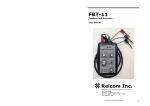
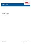
The Main Board
As Figure 2, the function of connection port as following:
1-the port “LINE” for telephone line
2-the port “PHONE” for telephone set
3-Dialing LED Indicator
4-the jumper “DEFAULT” for restore factory defaults
5―the connector for the voice module
6-the type and version number
7-eligible label and production serial number
8- “AUX” safety for assistant power, 0.5A
9― “BELL” safety for siren power, 1A
10-“BAT” safety for standby power, 2A
11-“BAT-” the cathode of the standby power
RP208CN User’s and Installer’s Manual
Page 17
12-“BAT+” the anode of the standby power
13/14-“AC” low-tension entry port for AC power (AC16.5V)
15-the port for ground
16-“BELL+” connect to the anode of detector
17-“BELL-” connect to cathode of detector
18-“UO” Utility Outputs
19/20-“AUX” connect to the anode of detector(s) “DC12V+”
22/25/28/31 - “COM” the communal port. In general, the port “COM”
should connect to of the anode of detector(S) “DC12V-” and one port
of the “ALARM” and “TAMPER”
21-“Z1” the port for zone 1, defaults as Entry/Exit Delay Zone. Connect
to one port of “ALARM” on the detector.
23/24-“Z2” for zone 2 and “Z3” for zone 3. Defaults as Instant (Intrusion)
Zone.
26-“Z4” the port for zone 4 defaults as Panic Zone. Suit for connect with
a panic button
27-“Z5” the port for zone 5 defaults as fire zone. Suit for connect with a
Gas Detector or a Smoke Detector.
29-“Z6” the port for zone 6 defaults as tamper zone. The user should
connect it with one of the port “TAMPER” on detector.
30/32-“Z7” the port for zone 7 and “Z8” zone 8, both of them are default
ed as Interior Zone. When arm by [STAY], the Interior Zone won’t be
armed.
33-“GRN” the port should connect to the green line on the keypad.
34-“YRL” the port should connect to the yellow line on the keypad.
35-“BLK” the port should connect to the black line on the keypad.
36-“RED” the port should connect to the red line on the keypad.
RP208CN User’s and Installer’s Manual
Page 18
Fig.2 RP208MB
RP208CN User’s and Installer’s Manual
Page 19
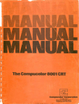
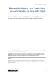
Fig.3 Connection Instruction
RP208CN User’s and Installer’s Manual
Page 20
Install Control Panel and Keypad
The RP208CN control panel should install in the aridity, near by AC power
supply which can't be power off and connect the ground well and be easy to
connect the phone line. Use correct tool, avoiding the damage toward the
equipments.
The keypad is generally installed in the open side of the entry, the height
should be easy to user. The Tamper Button on the back cover of the keypad
can prevent the keypad from being broken or tore down, turn on it and press it
tightly to the wall while installing.
Please connect the 4 lines of the keypad with the main board respectively
according to the red, black, yellow and green sequence. Such as Fig.3 shows.
Connect the Telephone Line
There are two twin ports of telephone lines on the mainboard. The ports which
mark LINE used for input, PHONE for telephone. Such as Fig.3 shows.
Connect the Standby Battery
Please provide a standby battery (DC12V) inside to panel in case of the AC
power is cut off.
Two lines marked BAT link the battery with anode+ (red) and the cathode
-(black) respectively. Such as Fig.3 shows.
Don't conjunction any power before connected all the lines well.
Connect Transformer
The output of transformer should be AC16.5V, connecting into the AC two ports
on the mainboard. When AC power is different, please carefully choose a right
transformer to be applicable to AC220V or perhaps AC110V. Remember: The
red lines for the high -voltage, do not mix with blue which is the low-voltage.
Don't power the system before the installation finished well.
Connect Siren
The port BELL is used for connect siren. Please watch for cathode and anode
when connecting.
RP208CN User’s and Installer’s Manual
Page 21
Connect Detector(s)
As the Fig.3 shows, the wiring work must be done without power.
1. Used and unused zone should connect with 2.2k Ω termination resistors.
When connecting detector, please install termination resistors in the detector,
to ensure the system of self-protection function.
2. The two ports of ALARM, one for COM port and another for alarm zone ports
respectively on the mainboard.
3. TAMPER ports of detector, connected to tamper zone and COM. When
there are many detectors, TAMPER port in series to access tamper zone and
COM port.
4. "+ DC12V -" in the detector connect AUX and COM respectively. Do not mix
anode and cathode.
5. Please connect the port of UO when need.
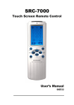
Connect Voice Module
As Fig.4, connecting voice module just need to insert it into the connector on
the control panel.
1(record)-recording button
2(play)-test record button
3 - the eligible label including production serial number, tester number,
production type and version number.
4-recording microphone
RP208CN User’s and Installer’s Manual
Page 22
Fig.4 Voice Module
Connect Remote Receiver
When arm or disarm by a remote controller, please programming a zone as
switch lock zone. And connect the remote receiver as following:
Fig.5 Remote Receiver
Connect Wireless Module
The function and the port of RP208EW4 expansion wireless module:
1
12VDC Power
11
Zone-1 Indicating Light
2
Set Aside
12
Zone-2 Indicating Light
3
Remote Armed
13
Zone-3 Indicating Light
4
Set Aside
14
Zone-4 Indicating Light
5
Trouble Output
15
Receive Data Indicating Light
6
Zone 1 Connector
16
Interfered
7
Zone 2 Connector
17
Setting Indicating Light
RP208CN User’s and Installer’s Manual
Page 23
8
9
10
Zone 3 Connector
Zone 4 Connector
Dial Switch
18
Trouble Indicating Light(1)
19
Trouble Indicating Light(2)
20
Touch Switch
21
Antenna Connector
1. 6-9 are corresponding 1-4 receiver’s channels, should be connected 4 of the
zones on RP208MB
2. The port +12v should connect to AUX on control panel, the GND port to the
COM.
3. When using remote controller, the port 3 should connect switch lock zone of
RP208CN
4. In normal, the dial 1 and 2 on the dial switch 10 should be set at the position
ON.
Please refer to RP208EW4 User's Manual for more details.
RP208CN User’s and Installer’s Manual
Page 24
Fig.6 The Wireless Receiver
RP208CN User’s and Installer’s Manual
Page 25
CHAPTER 4 - FUNCTION AND TECHNICAL DATA
You can communicate your RP208CN (8 zones control pane) through LCD
Keypads (RP208KCL). Each RP208CN can match with 4 LCD keypads at most.
With the LCD Keypad(s), you can operate your system by arm/disarm, bypass,
emergency, closing the siren, inspecting trouble, programming the system and so
on. The system status can be displayed by the LCD or/and indicator light.
All of your system’s detectors are wired to the control panel. As such, your
system always knows the status of any protected door, window, hallway, room, or
area.
The main board of RP208CN is RP208MB.
The main features of RP208CN include the RP208KCL and RP208MB.
Main Features Of RP208KCL
LCD can display the functions of system
3 Keypad Emergency Zones: Panic[1]+[2], Fire[4]+[5], Medical[7]+[8]
Key-press with Audible Feedback
LCD Backlight
System Status Display
LED Indication: Alarm, Power, Armed, Bypass, Ready, Tamper
Tamper is Supervised
Disarm by Code
Disarm by Remote Controller
Disarm By Duress Code
LCD Display Bypassing and Not-ready Zones
Quick Arm
Quick Arm by Code
Quick Stay Arm
Stay Arm by Code
Bypass zone quickly
Bypass zone by Code
RP208CN User’s and Installer’s Manual
Page 26
Main Features of RP208MB
Zones
8 programmable zones on Main Board
Special zones: Zone 5 - Fire Zone (default)
Zone 6 -tamper Zone (default)
11 types of Programmable Zones, 7 types of Voice Formats
Zone Terminal: NC, NO, Single End with Resistor 2.2KΩ
End Calling Function
Disarm/Arm Report can be set
Siren Driver
Built-in Siren Driver(750mA)
Clock
Built-in Digital Clock
Siren Voice Output
Siren Voice type is Programmable. Current output:750mA(max)
Built-in Digital Communicator
Attached Digital Communicator, Compatible with Contact ID,4+2
4 Follow-me Phone Numbers
2 Central Station Numbers
Code
1 Installation Code
1 Master Code, this Code Can Create Duress Code Automatically
9 User Codes, Each Code Can Create Duress Code Automatically
Periodic Test
Offer Testing Report to Alarm Center Automatically Every Day
Peripheral Equipment
RP208CN User’s and Installer’s Manual
Page 27
Voice module
Remote Control, Using for Disarm/Arm and Emergency
Wireless Receiver
Events Record
50 Events Record can be saved
Timing Function
Auto Daily Arm
Auto Daily Test report
Windows Disarm/Arm Report
Monitor Function
Trouble Data can be Displayed on Keypad, and Also can be Transmitted to
Central Station
Battery in Low Power
Siren Circuit in Trouble
AC Supply in Trouble
System Clock is Not Set
Tamper Prevention
Fire Alarm Circuit Trouble
UO Port
UO port can be activated when the system is Alarm, Arm or Disarm. (Welcome
check the location 22 in Chapter 5 for details)
Charging of Standby Battery
Main Board attaches charging circuit, the Standby Battery can be charged via
BAT port
TECHNICAL DATA
Main Board
Input power
16.5VAC 25VA via transformer
RP208CN User’s and Installer’s Manual
Page 28
Back-up Battery
Auxiliary Power
Siren port output
Programmable output
Switch zone output
Circuit Response Time
Fuse AUX
Fuse BELL
Fuse BAT
Dimension/weight
DC12V 4Ah, or DC12V 7Ah
12VDC 400mA maximum
12VDC 750mA maximum
Open collector Active pull down 70mA max
250mA
500mS
Auxiliary Power 0.5A
Bell/LS Power 1A
Battery Power 2A
80*167mm/0.17kg
Keypads
LCD Keypad
Current consumption
Control panel connections
Dimensions
Weight
90mA typical, 130mA max
4-wire up to 1000M from panel
110*130*25mm
0.23kg
RP208CN User’s and Installer’s Manual
Page 29
CHAPTER 5 – PROGRAMMING DIRECTION
Restoring Factory Defaults
Recover the default of the control panel before program:
1. Connect the keypad and the control panel
2. Check if the line have linked correctly on all the other port
3. Turn off all the power
4. Short circuit the default of the main board of the control panel(reference the
pic2 in page 19)
5. Reconnect the power(AC or the standby battery)
6. When you hear a brief sound ”beep-”, cut J1. At this moment, the default
has been recovered already.
7. Please check the signal light, when you in program mode, the light of
READY is flicker, at this time, you can program.
Program Explain
First confirm the Default jumper is off. Keep in disconnection when programming.
Programming is a process of altering or setting the location data of the control
panel, RP208CN has 94 locations 01-94 for setting data, and each data will
correspond to a different function of the control panel. The location are made up
of 2 digital, the data of location are made up of 1 digital, 2 digital or many digital.
RP208CN has the advantage of agility and compact in programming, user only
have to alter or set part or all the data of location. Not all location need to be set,
and most of the location can only use the default data.
Connect the mainboard and the control panel, use the RP208KCL keypad to
program when the power is on.
Check Location Data
Check location data need in the state of program mode. LCD display the relative
information after enter to the location which need to be checked, but the Code
won’t display.
RP208CN User’s and Installer’s Manual
Page 30
ENTRY/EXIT Program
According to the operation as below, you can enter into or exit the program state,
check location data, change the location data and so on
1. Enter into program mode: pres [#]+[master code]
2. Enter into the appointed location: [enter 2 digital location No.]+[ARM]. At this
time, the LCD will display the data of this location, but the Code will not
display
3. Enter into the next location: press [ARM]
4. Change location data: change the location data, press [#] to affirm. The
keypad will make a long sound “beep—” to show operating right, “beep,
beep, beep” short sound show operating wrong.
5. Exit programming mode: input the master code +[ARM]
A Programming Tutorial
To get acquainted with some programming basics, a short tutorial has been
prepared. It involves changing the Installer Code from the factory default of
0-2-0-6 to a sequence of you own choosing. If you can master this operation,
subsequent programming should be easy.
Operation
Action
Enter the Programming Enter the factory
Mode
default Installer
1
Code :
[#][0206]
Access the Installer
Press[0][8][ARM]
2 Code(stored in
Location"08")
Enter a unique Installer
3 Code (for this tutorial,
we'll use 5-6-7-8)
Store the data you
have entered
Enter[5][6][7][8]
No confirming beep
Press[#]
A long beep will sound
confirming that data has
been properly stored if a
wrong number of digits
entered three (error) beep
will sound after pressing [#]
[5678]
4
Check the data stored
5 in Location"08"
Comments
A long beep will sound,
confirming successful entry
into Installer Programming.
LCD display “ADD:”
No confirming beep
The data display
on the LCD
RP208CN User’s and Installer’s Manual
Page 31
Press the desired
two-digit location
and [ARM]
Enter your Installer
Code and press
[ARM]
Go to another location
6 of your choice
Exit programming
7
Press[ARM] along to go to
the next sequential location
A long beep will confirm your
actions
Data In the Location
General System Parameters: Locations 00-07
Location: 01
Preparation
Location: 02
Default: 00
the First Central Station phone number
Explain: To input or alter the phone number is required to enter the location and
input all digits include the area code. When done with your complete input, press
[#] to store it. Up to 20 digits can be entered to the location. To delete an existing
phone number, just press the Key [#].
To delete an existing phone number, simple press the [#] key; to enter or replace
the phone number required to reach the primary Central Station include all
access digits (e.g. 0 to 9) and the area code. When done with your complete
entry, press [#] to store it. Up to 20 digits can be entered to the phone number.
For your records, enter the complete phone number above. If required, include
the following special functions to achieve the effect listed in the table:
Location: 03
the Second Central Station phone number
Same as in Location 02
Location: 04
Location: 05
Preparation
User’s No.
Default: 0000
PURPOSE: to assign the system's Central Station Account Number.
Hexadecimal account numbers (those using 0 through 9 and A through F) are
accepted by RP208CN. Use the key combinations below to enter hexadecimal
digits "A" through "F"
Hex digit Press
Hex digit
Press
RP208CN User’s and Installer’s Manual
Acct No.
Page 32
A
[STAY], 1
D
[STAY], 4
B
[STAY], 2
E
[STAY], 5
C
[STAY], 3
F
[STAY], 6
"0" will not send a digit to the central station, to send "0" use "A" digit
Location: 06
Preparation
Location: 07
Preparation
Installer Code:Location 08-10
Location: 08
Installer Code I
Default: 0206
The installer code used by installer authorized to modify the system's parameters.
It is recommended to change the "factory default" Installer Code to one of your
own choice. It is made up by 4 digits. Default:0206
Location: 09
Installer Code II
Default: 1206
Same as the Installer Code 1, but with a few limitations: It can't modify the
"default code", observe and modify the first installer's codes, modify any phone
number, nor observe & modify MS lock code.
Location: 10
Master Code
Default: 1234
PUPROSE: to establish the keypad code for the system's "chief user"; the
Master Code provides the following special privilege:
1. Alter the master code and users’ code
2. Setting the clock;
3. Checking the trouble and the events record or other operation
4. System testing;
5. Set follow-me phone number
Note: the Master Code cannot be seen by the installer through the keypad.
System Time: Locations 11-13
Location: 11
Exit Delay
Default: 030
Location 11 is used to set the time of exit delay, which unit is second. The time of
delay is made up of 3 digits, 1 second at least, 255 second at most. For example,
030 means the delay time is 30 seconds. When arm, it won’t alarm to leave the
RP208CN User’s and Installer’s Manual
Page 33
locale in the time of exit delay.
Location: 12
Entry Delay
Default: 030
Location 12 is used to set the time of enter delay between 001 and 255. For
example, 030 means the delay time is 30 seconds. When enter into the locale, it
won’t alarm to disarm in the time of enter delay.
Location: 13
Bell cutoff Time
Default: 03
Location 13 is used to set auto alarm time of the External Sounder, before it
shuts down automatically. Enter the number of minutes between 01 and 90
Intrusion Zone Types and Zone Sounds:Locations 14-21
Locations 14 through 21 are identical and are corresponding to Zone 1 through
8 respectively. Each of these locations contains two digits. The first digit is used
to set the type of the zone, the second digit is used to set the type of the sound.
Attention: Each zone must be connected to an EOL 2.2KΩ resistance when
installing, even if the zone not in used.
1stDigit Zone Type and comment of Zone 1-8
0
1
2
3
4
Not Used
All unused zones should be given this designation. lt is also used to
disable a zone
Enter/Exit Delay
If violated, a zone with this designation will not cause an intrusion
alarm during the Entry and Exit Delay periods.
Instant(Intrusion)
Causes an immediate intrusion alarm if violated when the system is
in arm state.
Entry Follower
A zone(s) given this designation will cause an immediate intrusion
alarm when violated unless an Entry/Exit zone was violated first if so,
an Entry Follower zone(s) will remain bypassed until the end of the
Entry Delay period.
Interior + Entry Delay Follower
If the system is armed to AWAY (ARM) mode: this type of zone
behaves like the Entry Follower, described above If the system is
armed to the STAY mode: this type of zone will be bypassed.
RP208CN User’s and Installer’s Manual
Page 34
5
Fire Zone
Intended for smoke or other types of fire detectors. If violation, will
cause an immediate fire alarm, regardless of the system's
armed/disarmed state.
Suggest Zone 5 can be programmed as a fire zone. A fault in the
wiring of any fire zone, if supervised, will cause a fire alarm ,
manifested by a rapid flushing of the keypad's Fire LED.
6
Tamper Zone
If violation, will cause an immediate tamper alarm, regardless of the
system's armed/disarmed state. Suggest Zone 6 on RP208CN to be
a Tamper Zone.
7
8
2ndDigit
0
1
(default
)
2
3
4
5
Panic Zone
If violated an immediate panic alarm will be announced , regardless
of the system's armed /disarmed state.
Key-switch Zone-Instant
If desired for system arming and disarming an external SPST
spring-loaded, normally open, momentary type key switch can be
added. The key switch permits an instant disarming of the system
after tripping. And when arming the system an exit delay will follow.
Zone sound and comments of Zone 1-8
Silent
A violation during the armed period will produce no sound. The
resulting alarm can still be reported to the Central Station
External sounder (continuous)
Cause the external sounding device to annunciate steadily, without
breaks in the sound cadence the sound will continue until the
sounder "times out" or the system is disarmed
External sounder (pulses)
Cause the external sounding device to produce a pulsed (of
staggered) annunciation this sound is usually recommended for fire
alarm annunciation.
Keypad sounder Only
Cause the piezo sounder within the system's keypad(s) (only) to
beep rapidly
External sounder +Keypad Sounder
Causes the external sounding device to annunciate continuously,
without breaks in the sound cadence causes the piezo sounder
within the system's keypad(s) to beep rapidly
External Sounder When Armed/keypad Sounder When
Disarmed
Related to 24H Zones.
When alarm during disarm, the keypad's buzzer will be activated
When alarm during armed system, the external sounder will be
activated.
RP208CN User’s and Installer’s Manual
Page 35
6
Door Chime
Assigned to an opening which, when violated during the disarmed,
will cause the system's keypad(s) to beep once during an alarm,
the external sounding device will annunciate continuously, without
interruption. When alarm occurs during armed system only the
external sounder will be activated.
For example:if the zone 1need to set to be entry/exit delay zone, and need the
exterior alarm intermittent sound at the same time keypad buzzer sound when
need to alarm, then input 14 in location 14. If the 3 zone need to set to be
active zone, and need the exterior alarm intermittent alarm, then input 32 in
locate 16. The zone characteristic of default:
Zone 1: Entry/Exit Delay Zone; zone type is 11
Zone 2: Instant (Intrusion) Zone; zone type is 21
Zone 3: Instant (Intrusion) Zone; zone type is 21
Zone 4: Panic Zone; zone type is 70
Zone 5: Fire Zone; zone type is 52
Zone 6: Tamper Zone; zone type is 61
Zone 7: Interior Zone; zone type is 41
Zone 8: Interior Zone; zone type is 41
Special Zones Suggestion:
a.
Zone 5 is reserved as a Fire Zone, Supports Smoke Detectors and/or Gas
Detectors. A fire zone cannot be disabled or bypassed. For fire zone the
recommended (default) zone sound is "External sounder pulsed". However it
is possible to change the zone sound and type to any of the ones provided
in the previous list.
b.
Urgency zone alarm doesn’t result the siren sound but calling to the CMS or
follow-me numbers.
c.
Zone 6 on the RP208CN is reserved as a Tamper Zone. This zone can be
programmed to any zone type. If the zone was programmed as Tamper, in
violation, a Tamper Code report will be sent and the Tamper LED on the
keypad will light up.
Utility Outputs- Event and Result:Locations22, Default 00
The RP208CN supports one open collector Utility Output (derived between the
RP208CN User’s and Installer’s Manual
Page 36
UO/ECL and AUX terminals) which can be used for switching an external device
on or off. Once the Utility Output is activated the device will be connected
between AUX (+12V) and ground (0V). This connection is capable of switching
light loads of no more than 70mA.
When input different data in locate 22, UO will active in different way.
Digit
00
(default)
01
02
03
04
05
06
07
08
09
Event and Result
Not Active
UO offers no response to any system activity UO
preparation
Arm Follow (Latch)
UO is activated when the system is armed. The activation occurs
after the expiration of the exit/delay period. The UO remains
active (latched) while the system is armed. When disarming the
system the UO deactivates (Unlatches).
Arm Follow (Pulse)
UO is activated when the system is armed .The activation occurs
after the expiration of the exit/delay period. The UO is activated
for several seconds (pulse), after which is deactivated.
Alarm Follow (Latched)
UO is immediately activated when the system goes into any type
of alarm (i.e. intrusion, fire, keypad-initiated panic) UO remains
active (latched) for the duration of the alarm-even after the
system's sounder "times out" UO is deactivated when the system
is disarmed.
Alarm Follow (Pulse)
UO is immediately activated of several seconds and then
deactivated whenever the system goes into any type of alarm
(i.e. intrusion, fire, keypad-initiated panic)
Panic Follow (Latched)
UO is activated immediately when a PANIC alarm is triggered by
a violation of a zone, defined as Panic, or by pressing the
keypad's [1] and [2] keys simultaneously for two seconds. UO is
deactivated when the system is disarmed.
Panic Follow (Pulse)
UO is activated for several seconds when a PANIC alarm is
triggered by a violation of a zone, defined as Panic, or by
pressing the keypad's [1] and [2] keys simultaneously for two
seconds.
Fire Keying Follow (Latched)
UO is activated immediately when a Fire alarm is triggered by a
violation of zone 5, defined as Fire, or by pressing the keypad's
[4] and [5] keys simultaneously for two seconds, UO is
deactivated when the system is disarmed.
Fire Keying Follow (Pulse)
UO is activated when a Fire alarm is triggered by violation of
zone 5, defined as Fire, 0r by pressing the keypad's [4] and [5]
RP208CN User’s and Installer’s Manual
Page 37
keypad's simultaneously for two seconds.
10
11
12
13
14
15
16
17
18
19
20
21
22
23
24
25
26
27
28
29
30
31
32
Special Emergency Keying Follow (Latched)
UO is activated immediately when pressing the keypad's [7] and
[8] keys simultaneously for two seconds. UO is deactivated when
the system is disarmed.
Special Emergency Keying Follow (Pulsed)
UO is activated for several seconds when pressing the keypad's
[7] and [8] keys simultaneously for two seconds.
Duress Code Follow(Pulse)
UO is activated for several seconds (and then deactivates) when
any duress code is entered.
Duress Code Follow (Latched)
UO is activated when any duress code is entered.
AC Loss Follow (Latched)
UO is activated due to a lack of power from the commercial AC.
UO is deactivated when the system is operating properly from
commercial (AC) power.
AC Loss Follow (Pulse) AC
UO is activated for several seconds (and then deactivates) due
to a lack of power from the commercial AC.
Low Battery Follow (Latched)
UO is activated due to low power from the backup battery. UO1
is deactivated when the battery is in good condition.
Low Battery Follow (Pulse)
UO is activated for several seconds due to low power from the
backup battery.
Zone 1 Alarm Follow (Latched)
UO is immediately activated when an alarm occurs on Zone 1.
UO remains active (latched) for the duration of the alarm-even
after the system sounder "times out". UO is deactivated when
Zone 1 goes into normal condition.
Zone 1 Alarm Follow(Pulse)
UO is immediately activated for several seconds (pulse) and then
deactivates whenever Zone 1 goes into alarm.
Zone 2 Alarm Follow(Latched)
Zone 2 Alarm Follow(Pulse)
Zone 3 Alarm Follow(Latched)
Zone 3 Alarm Follow(Pulse)
Zone 4 Alarm Follow(Latched)
Zone 4 Alarm Follow(Pulse)
Zone 5 Alarm Follow(Latched)
Zone 5 Alarm Follow(Pulse)
Zone 6 Alarm Follow(Latched)
Zone 6 Alarm Follow(Pulse)
Zone 7 Alarm Follow(Latched)
Zone 7 Alarm Follow(Pulse)
Zone 8 Alarm Follow(Latched)
RP208CN User’s and Installer’s Manual
Page 38
33
Zone 8 Alarm Follow(Pulse)
Communication Parameters:Locations26-29
Locations 26 and 27 allow you to define the manner in which the RP208CN
communicates with the Central Station when it reports alarms, Restores, troubles,
openings/closings, and tests.
Digital Communicator Controls:Locations 26, Default 41
First digit: determines the number (or hexadecimal digit) corresponding to
the Dialing Method/Duty Cycle /Redial Time desired
Second digit: determines the number corresponding to the Attempts
/Answering Machine Use /UL Installation
Attempts: Attempts sets the Number of times the control panel will redial the
Central Station after failing to establish a successful communication,
Voice Module: If enabled ("YES") voice messages will be sent. If "NO" then
tones will be used to represent an active alarm.
Dialer Controls:(1stDigit)
Location: 26
1Digit
Dialing Method
Duty Cycle
1
2
3
4 (default)
Pulse @20 pps
Pulse @10 pps
Pulse @10 pps
DTMF
67/33
67/33
61/39
N/A
Location: 26
2Digit
0
1 default)
8
9
Redial Central
Station
After 30 seconds
After 30 seconds
After 30 seconds
After 30 seconds
Dialer Controls: (2Digit):
Attempts
Voice Module
8
No
3
No
3
Yes
8
Yes
Central Station Protocols:Location 27, Default: 00
To understand and modify the Code format according to a specific central station
see the following
First digit: determine the number corresponding to the desired combination of:
Kiss-off/ Handshake Freq/ Message Validation/ Extended-Non-Extended
Format
RP208CN User’s and Installer’s Manual
Page 39
Second digit: determine the number (or letter) corresponding to the desired
Combination of: Dialing Rate/ Inter digit Time /Date Frequency
CS Protocols: (1stDigit)
Location: 27
1stDigit
Format
Kiss-off/Handshake
Freq
0(default)
Non-Extended
1400Hz
1
Non-Extended
2300Hz
2
3
Non-Extended
Non-Extended
1400Hz
2300Hz
4
Extended 扩展
1400Hz
5
Extended
2300Hz
6
7
Extended
Extended
1400Hz
2300Hz
Location:27
2ndDigit
0(default)
1
2
3
4
5
6
7
8
9
A
B
C
D
E
F
Format Name
Silent
Knight/ADEMCO
Slow
Silent
Knight/ADEMCO
Slow Extended
Message
Validation
Dual Round
Compare
Dual Round
Compare
Parity
Parity
Dual Round
Compare
Dual Round
Compare
Parity
Parity
nd
Date Rate
40 pulses/sec
33 pulses/sec
20 pulses/sec
10 pulses/sec
40 pulses/sec
33 pulses/sec
20 pulses/sec
10 pulses/sec
40 pulses/sec
33 pulses/sec
20 pulses/sec
10 pulses/sec
40 pulses/sec
33 pulses/sec
20 pulses/sec
10 pulses/sec
CS Protocols:(2 Digit)
Inter digit Time
Date Frequency
390ms
1800Hz
390ms
1800Hz
390ms
1800Hz
390ms
1800Hz
650ms
1800Hz
650ms
1800Hz
650ms
1800Hz
650ms
1800Hz
390ms
1900Hz
390ms
1900Hz
390ms
1900Hz
390ms
1900Hz
650ms
1900Hz
650ms
1900Hz
650ms
1900Hz
650ms
1900Hz
(PPS)
Kiss off/
Inter Digit
Validation
Time
pulses/sec Handshake
Code
Format
10
1400Hz
Dual
round
650
0F
10
1400Hz
Dual
round
650
4F
RP208CN User’s and Installer’s Manual
Page 40
Radionics
/DCI/Franklin Slow
10
2300Hz
Silent Knight Fast
20
1400Hz
20
1400Hz
20
2300Hz
Universal high speed
20
2300Hz
Radionics
20
1400Hz
Radionics
20
2300Hz
Radionics Extended
20
1400Hz
Radionics Extended
20
2300Hz
Radionics
40
1400Hz
Radionics
40
2300Hz
Radionics Extended
40
1400Hz
Radionics Extended
40
2300Hz
Radionics
Radionics
Radionics Extended
Radionics Extended
40
40
40
40
1400Hz
2300Hz
1400Hz
2300Hz
Silent Knight Fast
Extended
Sescoa / Franklin/
Vertix/DCI
Extended
Dual
round
Dual
round
Dual
round
Dual
round
Dual
round
Dual
round
Dual
round
Dual
round
Dual
round
Dual
round
Dual
round
Dual
round
Dual
round
Parity
Parity
Parity
Parity
650
17
650
0E
650
4E
650
56
390
12
390
02
390
12
390
42
390
52
390
00
390
10
390
40
390
50
390
390
390
390
20
30
60
70
CS Protocols: Location 28, default: 03
When selecting 01 (the contact ID) format, all the reporting codes will be
automatically applied to the locations of the reporting codes.
When selecting 03 (the Pulsed Protocol) the default for all the reported codes will
be "00"and any other code should be entered manually follow the CMS software.
Digit
Format Name
Inter-digit Time
Date Frequency
01
Contact ID
NA
NA
03(default)
4+2
Location: 29
Preparation
System Controls:Location 30, Default 13
RP208CN User’s and Installer’s Manual
Page 41
Location 30 allows you to specify some additional parameters, which determine
how the control panel will operate. The location contains two digits.
Comments on system controls (Location 30:1stDigit)
Quick Arm: Eliminates the need for entering a User Code when arming to the
STAY or AWAY modes. Simply pressing [STAY]or[ARM] will arm the system to
the respective mode
Loudspeaker/Bell-Siren: Select Loudspeaker if the external sounder(s) NOT
equipped with a built-in sound driver; doing so causes the panel to produce an
oscillating frequency for the device, select Bell/Siren if the external sounder(s) is
a bell or a buzzer or equipped with a built-in electronic sound driver
Quick Bypass: Eliminates the need to enter a User Code when bypassing a
zone.
Silent Panic: If "NO", the panic alarm will be AUDIBLE at the External Sounder
and visual on the keypad. If "YES", the panic alarm will be INAUDIBLE at the
External Sounder and invisible on the keypad and there will be no audible
kiss-off.
Bell Squawk On Arming:
If selected, Bell Squawk on Arming will produce a
brief confirmation "chirp" from the system's external sounder(s) once the system
is armed and the Exit Delay expires.
3 Minute Bypass Enabled: If selected, 3-Minute Bypass Enabled bypasses all
zones automatically for 3 minutes when power is restored to an "un-powered"
system-to prevent potential false alarms by allowing time for the stabilization of
motion and/or smoke detectors.
First digit: determine the number(or letter)corresponding to the choices
involving Quick Arm/Quick Bypass/Loudspeaker/Bell-Siren
Second digit: determine the number (or letter)corresponding to the use of
silent Panic/Bell Squawk on Arming /3 Minute Bypass
Location:30
1stDigig
0
1(default)
st
System Controls: (1 Digig)
Quick
Loudspeaker/Bell-Siren
Arm
Bell-Siren
NO
Bell-Siren
YES
RP208CN User’s and Installer’s Manual
Quick Bypass
YES
YES
Page 42
4
5
8
Location:30
Bell-Siren
Bell-Siren
Loudspeaker
NO
YES
YES
YES
YES
NO
System Controls:( 2ndDigit)
2ndDigit
3 Minute Bypass
0
1
2
3(default)
4
Enabled
Enabled
Enabled
Enabled
Disabled
Silent
Panic
NO
YES
NO
YES
NO
Bell Squawk On Arm
NO
NO
YES
YES
NO
Periodic Test Time:Location 31
If desired, the RP208CN can send a daily test transmission to the Central Station
to Verify the operation of the Unit's Digital Communicator.
Location:31
Periodic Test Time
Default: 0000
Sets a fixed, daily time for sending an test transmission to the Central Station.
The chosen time is expressed in 24-Hour format (following examples): 8:30
AM=0830 11:15AM=1115, 4:30 PM=1630 If desired, disable the test transmission
capability by accepting (or entering) the default (0000)
Note: Failure to set the systems' time clock, will prevent the code from being
sent to the Central Station.
Communicator Reporting Codes:Locations 32-94
The reporting codes is a report when the system has something happened to
give a report to the alarm center. Different status will send different report.
Reporting Codes for Alarm Events:
To program the codes that will be transmitted by the RP208CN to the Central
Station.
To prevent the corresponding event from being reported, use a "double-zero"(00,
the default) in the location.
Notes on Alarm Restores:
An RP208CN Restore Repot informs the Central Station that the external
sounder's operation, initially triggered by the respective alarm condition, has
RP208CN User’s and Installer’s Manual
Page 43
either "timed out" or been silenced by the act of system disarming. Be sure to
check with Central Station personnel if restore are permitted and, if so, what
codes are required.
Annotate: When the communicate protocol is CID, separated codes is the same
as restore codes(ABC), input the last 3 digit: OABC;
When the communicate protocol is4+2, the first 2 digit are separated reporting
codes(AB), the last 2 digit are restore reporting codes(CD), total are 4 digit:
ABCD
Hex date fast operation
Locatio
n
32
33
34
35
36
37
38
39
40
41
42
43
44
45
46
47
48
49
50
51
52
53
54
55
A=[STAY]+[1]
B=[STAY]+[2]
C=[STAY]+[3]
D=[STAY]+[4]
E=[STAY]+[5]
F=[STAY]+[6]
Description
Zone 1 Alarm Reporting code
Zone 2 Alarm Reporting code
Zone 3 Alarm Reporting code
Zone 4 Alarm Reporting code
Zone 5 Alarm Reporting code
Zone 6 Alarm Reporting code
Zone 7 Alarm Reporting code
Zone 8 Alarm Reporting code
Keypad Fire Alarms Reporting code
Keypad Panic Reporting code
Keypad Special Emergency Reporting
code
Zone 1 Restore code
Zone 2 Restore code
Zone 3 Restore code
Zone 4 Restore code
Zone 5 Restore code
Zone 6 Restore code
Zone 7 Restore code
Zone 8 Restore code
Keypad Fire Restore code
Keypad Panic Restore Code
Keypad Special Emergency Restore
Code
User 0 arm (the "Master" Code,
"Quick Arm" OR "Keyswitch" Arm)0
User 1 arm Reporting code
RP208CN User’s and Installer’s Manual
Num
3
3
3
3
3
3
3
3
3
3
Report
Code
000
000
000
000
000
000
000
000
000
000
3
000
3
3
3
3
3
3
3
3
3
3
000
000
000
000
000
000
000
000
000
000
3
000
3
000
3
000
Digit
Page 44
56
57
58
59
60
61
62
63
64
65
66
67
68
69
70
71
72
73
74
75
76
77
78
79
80
81
82
83
84
85
86
87
88
89
90
User 2 arm Reporting code
User 3 arm Reporting code
User 4 arm Reporting code
User 5 arm Reporting code
User 6 arm Reporting code
User 7 arm Reporting code
User 8 arm Reporting code
User 9 arm Reporting code
User 0, disarm Reporting code
(Key switch disarm)
User 1, disarm Reporting code
User 2, disarm Reporting code
User 3, disarm Reporting code
User 4, disarm Reporting code
User 5, disarm Reporting code
User 6, disarm Reporting code
User 7, disarm Reporting code
User 8, disarm Reporting code
User 9, disarm Reporting code
Auto ARM report code
Forced arm (when the system is
armed with a bypassed zone )
Reporting code
Stay arm when the system is armed
to the Stay (At Home mode)
Reporting code
Duress Disarm
Daily test Report Code sent everyday
at the time specified in Location 24
Low Battery Reporting code
Loss of AC Power(for at least 15 min)
Reporting code
Fire zone trouble Reporting code
Bell Loop Interrupted Reporting code
Low Battery restore Reporting code
Loss of AC Power restore Reporting
code
Fire zone trouble restore Reporting
code
Bell Loop Restored Reporting Code
Zone 1 Bypass / Restore Reporting
code
Zone 2 Bypass / Restore Reporting
code
Zone 3 Bypass / Restore Reporting
code
Zone 4 Bypass / Restore Reporting
code
RP208CN User’s and Installer’s Manual
3
3
3
3
3
3
3
3
000
000
000
000
000
000
000
000
3
000
3
3
3
3
3
3
3
3
3
3
000
000
000
000
000
000
000
000
000
000
3
000
3
000
3
000
3
000
3
000
3
000
3
3
3
000
000
000
3
000
3
000
3
000
4
ABCD
4
ABCD
4
ABCD
4
ABCD
Page 45
91
92
93
94
Zone
code
Zone
code
Zone
code
Zone
code
5 Bypass / Restore Reporting
6 Bypass / Restore Reporting
7 Bypass / Restore Reporting
8 Bypass / Restore Reporting
RP208CN User’s and Installer’s Manual
4
ABCD
4
ABCD
4
ABCD
4
ABCD
Page 46
RP208CN Control Panel Contact ID reporting codes
Event reporting
Contact ID
Zone alarm/unarm
Report
code
Entry/exit alarm
134
Entry/exit Restore
134
Panic alarm
130
Panic Restore
130
24 hours zone alarm
133
24 hours zone Restore
133
Tamper zone alarm
137
Tamper zone Restore
137
Smoke induce zone alarm/Restore
111
Fire zone alarm/Restore
112
Waterproof zone alarm/Restore
113
High temperature zone alarm
114
High temperature zone Restore
114
Pipeline zone alarm/Restore
116
Fire zone alarm/Restore
117
Warning sound alarm
122
Warning sign alarm
123
Perimeter zone alarm/Restore
131
Interior zone alarm/Restore
132
Daytime/nights zone alarm/Restore
135
Open zone alarm/Restore
136
System zone alarm/Restore
140
Detector tamper zone alarm/Restore
144
24 hours zone alarm/Restore
151
gas-fired alarm
151
gas-fired alarm Restore
151
Low temperature zone alarm/Restore
152
temperature dissipate alarm/Restore
153
Liquid leak alarm
154
Liquid leak Restore
154
Oil leak alarm/Restore
155
Gas leak alarm/Restore
157
High temperature alarm/Restore
158
temperature dissipate alarm/Restore
159
Airflow unsteady alarm
161
RP208CN User’s and Installer’s Manual
Page 47
special function
urgency key-press alarm
urgency key-press Restore
Fire zone alarm
Fire zone Restore
Fire key-press alarm
Fire key-press Restore
Medical
treatment
emergency
alarm
Medical
treatment
emergency
Restore
menace alarm
Menace Restore
100
100
110
110
115
115
120
120
121
121
Fault reporting
AC fault
AC Restore
Battery power low
Battery power Restore
Warning sign fault
Warning sign Restore
Fire zone fault
Fire zone Restore
On/off reporting
User arm
User unarm
User 0 quick arm/unarm
Force arm
periodic test
301
301
302
302
321
321
373
373
6A
6A
62
63
64
RP208CN User’s and Installer’s Manual
401
401
408
574
602
Page 48
RP208CN
Installer Programming Worksheet
Customer
Address
City
Customer Phone No:(
)
Central Station Account No:
Comments
Date of Installation:
Installer(s):
Comments:
Location
00
01
02
03
04
05
06
07
08
09
10
11
12
13
14
15
16
17
18
19
20
21
22
23
24
25
26
27
28
29
30
31
32
33
34
35
Description
State
Entry
Zip
Remark
Phone No. CS 1
Phone No. CS 2
CS Account No.
Installer Code 1
Installer Code 2
Master Code
Exit Delay
Entry Delay
Bell cutoff Time
Zone 1 Settings
Zone 2 Settings
Zone 3 Settings
Zone 4 Settings
Zone 5 Settings
Zone 6 Settings
Zone 7 Settings
Zone 8 Settings
Utility Output
Dialer Controls
CS Protocols 1
CS Protocols 2
System Controls
Periodic Time Set
Zone 1 Alarm
Zone 2 Alarm
Zone 3 Alarm
Zone 4 Alarm
RP208CN User’s and Installer’s Manual
Page 49
36
37
38
39
40
41
42
43
44
45
46
47
48
49
50
51
52
53
54
55
56
57
58
59
60
61
62
63
64
65
66
67
68
69
70
71
72
73
74
75
76
77
78
79
80
81
82
Zone 5 Alarm
Zone 6 Alarm
Zone 7 Alarm
Zone 8 Alarm
Kpd Panic Alarm
Kpd Fire Alarm
Kpd SP Alarm
Restore Code Zone 1
Restore Code Zone 2
Restore Code Zone 3
Restore Code Zone 4
Restore Code Zone 5
Restore Code Zone 6
Restore Code Zone 7
Restore Code Zone 8
Restore Kpd Fire
Restore Kpd Panic
Restore Kpd SP
User 0 Arm
User 1 Arm
User 2 Arm
User 3 Arm
User 4 Arm
User 5 Arm
User 6 Arm
User 7 Arm
User 8 Arm
User 9 Arm
User 0 disarm
User 1 disarm
User 2 disarm
User 3 disarm
User 4 disarm
User 5 disarm
User 6 disarm
User 7 disarm
User 8 disarm
User 9 disarm
Auto ARM
Forced arm
Stay Arm
Duress Disarm
Daily test Report
Rpt Code Low Bat
Rpt Code AC Loss
Rpt Code Fire Tb
Rpt Code Bell Loop
RP208CN User’s and Installer’s Manual
Page 50
83
84
85
86
87
88
89
90
91
92
93
94
Restore Code Low Bat
Restore Code AC Loss
Restore Code Fire Tbl
Restore Code Bell Loop
Zone 1 Bypass / Restore
Zone 2 Bypass / Restore
Zone 3 Bypass / Restore
Zone 4 Bypass / Restore
Zone 5 Bypass / Restore
Zone 6 Bypass / Restore
Zone 7 Bypass / Restore
Zone 8 Bypass / Restore
Phone1
Phone2
RP208CN User’s and Installer’s Manual
Page 51