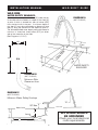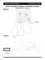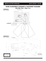
1
WILD RIDE™ SLIDE
Assembly & Installation Instructions
IMPORTANT
THESE INSTRUCTIONS
MUST REMAIN WITH
THE SLIDE OWNER!
Visit inter-fab.com to view our installation help video.
(Video does NOT replace installation instructions.)
WARNING: IMPORTANT INSTALLATION INFORMATION
The installation of this product should be done only by a licensed and professional installer. Installation should
be done strictly in conformance with all local building codes, electrical codes and other building and safety laws
and regulations. Among other things, that your installer should carefully analyze the need to bond the product
to prevent an electrical hazard. Failure to properly install this product could result in a dangerous condition,
including but not limited to electrical or structural hazards. Inter-Fab, Inc. disclaims all liability arising from the
installation and the user assumes all risk associated with the installation.
I N T E R - F A B , I N C . 3 0 5 0 S . A L V E R N O N W AY • T U C S O N , A Z 8 5 7 1 3
520.790.7040 • 800.737.5386 • FAX 520.790.7127 • inter -fab.com
WRS-IM Rev. 7/15 (SBK-INST WRS)
INSTALLATION MANUAL
WILD RIDE™ SLIDE
TABLE OF CONTENTS:
Intended Use Instructions ........................................................2
Water Safety Envelope.............................................................3
Slide Placement & Footprint Diagrams - Left Turn........................4
Slide Placement & Footprint Diagrams - Right Turn......................5
Tips & Tools for Slide Assembly ................................................6
Step 1: Measure the Pool........................................................7
Step 2: Flume Assembly ..........................................................7
Step 3: Legs to Flume Assembly...............................................7
Step 4: Attach Deck Anchors to Legs........................................8
Step 5: Assemble Steps ..........................................................8
Step 6: Stand Up the Slide.......................................................8
Step 7: Attach “L” Brackets to Steps.........................................8
Step 8: Align Flume Sections....................................................8
Step 9: Attach Handrails to Steps.............................................9
Step 10: Attach Steps to Flume ...............................................9
Step 11: Place Slide in Final Position .......................................10
Step 12: On Deck Installation .................................................10
Step 13: In Deck Installation...................................................10
Step 14: Attach Water Supply................................................11
Step 15: Attach Protective Caps.............................................11
Step 16: Provide Homeowner with Owner’s Manual ...................11
Inspection Check List.............................................................11
Slide Care & Maintenance......................................................12
Paver Kit Installation..............................................................13
Exploded View of White Water Slide ........................................14
Parts List (corresponds with exploded view)..............................15
Hardware Kit Information .......................................................16
Notes..................................................................................17
Inter-Fab, Inc. Limited Warranty..............................................18
WRS-IM Rev. 7/15 (SBK-INST WRS)
1
INSTALLATION MANUAL
WILD RIDE™ SLIDE
INTENDED USE INSTRUCTIONS
1.
2.
3.
4.
5.
6.
7.
8.
9.
10.
11.
12.
13.
14.
15.
16.
17.
18.
19.
20.
21.
22.
23.
24.
Everyone who uses this slide must know, understand and follow these instructions
The ANSI/APSP/ICC-5 2011 standard for above ground pools prohibits the use of slides or diving boards
on above ground pools.
This Slide is designed for residential inground pool use ONLY. This slide may not be used on any
above ground pool. Such use of this slide may result in serious injury or death.
This slide should never be installed on above ground pools, ponds, floating docks or platforms, boat docks
or houseboats or any natural body of water.
This slide should never be installed on any commercial, public or semi-public pool.
Be Familiar with the shape and depth of the pool before you slide. This slide should only be used with the
proper water safety envelope, as described in Diagrams A, B and C page 3 and in accordance with the
slide positioning instructions, as described in Diagrams D, E, F and G on pages 4 and 5.
Because the slide may only be used in water 4’ deep or greater, all slide users must be able to swim in
deep water.
Weight limit for this slide is 250 pounds, no slider weighing more than 250 pounds may use this slide.
The surface of the slide is very slippery when wet; USE CAUTION when entering the slide and when
transitioning from standing to sitting.
Slide in a feet first sitting position ONLY.
IMPORTANT: sliding headfirst is prohibited: serious spinal injury resulting in paralysis or death can result.
Maintain adult supervision at all times.
Only one person at a time is allowed on the slide; this includes the ladder.
Be sure the water delivery system is on and lubricating the slide prior to use.
Collision with another swimmer or a diver can result in serious injury or death for one or both persons:
Before sliding, always make sure that the path in front of the slide is free from any (including submerged)
obstructions including other people or objects in the pool such as rafts, inner tubes etc. When a diving
board is also present, make sure you do not use the slide while someone is on or using a diving board.
Take turns.
No roughhousing or horseplay should be allowed on the slide at any time.
Do not stand, jump or dive from any part of the slide.
Do not slide on objects such as rafts or inner tubes. doing so greatly increases your risk of injury.
Do not slide through or at objects such as rafts or inner tubes, doing so greatly increases your risk of
injury.
Do not use this slide if physically impaired or handicapped without your doctor’s permission.
Do not use this slide with a history of heart conditions, seizures, back problems, fainting or fear of
heights.
Do NOT use this slide if you are pregnant.
Do not drink alcohol and use this slide.
Don’t take chances, inspect the slide at least once a year (see the slide inspection list on page 11), do
not use the slide if any part becomes loose, damaged, weakened or broken. If necessary, before using
the slide again, have it inspected and repaired by a competent professional familiar with pool slides.
WARNING: SERIOUS INJURY OR DEATH CAN RESULT FROM THE
IMPROPER INSTALLATION OR USE OF THIS SLIDE.
SLIDE IN A SITTING
POSITION ONLY
DO NOT SLIDE HEAD FIRST
SERIOUS INJURY
CAN RESULT
DEEP WATER
SWIMMERS
ONLY
Face forward on the slide, holding the legs and arms
with the palms of your hands forward and tilted up.
When installed according to these instructions, this slide conforms to
Consumer Product Safety Standard Guidelines.
WRS-IM Rev. 7/15 (SBK-INST WRS)
2
INSTALLATION MANUAL
WILD RIDE™ SLIDE
WILD RIDE
WATER SAFETY ENVELOPE:
DIAGRAM A
A minimum water depth of three feet (3') under the exit
of the slide which increases to a depth of four feet (4')
at point A which is located four feet six inches (4'6")
from the back wall of the pool. A minimum depth of
four feet (4') must be maintained at a distance of nine
feet (9') along the centerline of the slide from point A.
The above described water depth profile shall extend a
minimum of three feet three inches (3'3") on either
side of the centerline of the slide.
(See Diagrams A, B & C)
C/L
4'6
"
3'
EN
TE
R
20" Max
13
'6"
C
13'6"
3'3"
4'
3'3"
6'6"
(NOT TO SCALE)
6'6"
2'6"
WATER SAFETY
ENVELOPE
DIAGRAM B
(NOT TO SCALE)
Minimum Slide
Clearance Area
DIAGRAM C
(NOT TO SCALE)
Minimum Water Safety Envelope
20" Max
Water Level
4'
Point A
9'
13'6"
WRS-IM Rev. 7/15 (SBK-INST WRS)
15˚
Level Deck
3'
4'
ALL SLIDES SHOULD
BE GROUNDED
Check your local electrical
code requirements.
4'6"
3
INSTALLATION MANUAL
WILD RIDE™ SLIDE
SLIDE PLACEMENT DIAGRAM & FOOTPRINT DIAGRAM
Wild Ride Slide - Left Turn
DIAGRAM D
(NOT TO SCALE)
3” MINIMUM
OVERHANG
DIAGRAM E
(NOT TO SCALE)
RECOMMENDED
MIN. DECK AREA:
12’ x 5’
WRS-IM Rev. 7/15 (SBK-INST WRS)
4
INSTALLATION MANUAL
WILD RIDE™ SLIDE
SLIDE PLACEMENT DIAGRAM & FOOTPRINT DIAGRAM
Wild Ride Slide - Right Turn
DIAGRAM F
(NOT TO SCALE)
3” MINIMUM
OVERHANG
DIAGRAM G
(NOT TO SCALE)
RECOMMENDED
MIN. DECK AREA:
12’ x 5’
WRS-IM Rev. 7/15 (SBK-INST WRS)
5
INSTALLATION MANUAL
WILD RIDE™ SLIDE
RECOMMENDED TOOLS FOR ASSEMBLY
AND INSTALLATION OF G-FORCE SLIDE:
ASSEMBLY TOOLS:
• Socket wrench
• 7/16”, 9/16” & 3/4” sockets and extensions
• 7/16” & 9/16” wrenches
• 5/32” Allen wrench
• Hammer Drill
• 3/8” masonry drill bit (not shown)
• Vice Grips or Clamps (Optional: not shown)
• Step stool/ladder (not shown)
• Center Punch
NOTE: USE PROVIDED ANTI-SEIZE ON ALL BOLTS!
READ THIS ENTIRE INSTALLATION MANUAL
BEFORE ATTEMPTING THE INSTALLATION
TIP: USE ANTI-SEIZE (PROVIDED) ON ALL BOLTS TO MINIMIZE SEIZING HARDWARE.
TIP: Use the box the slide came in to assemble the flume sections and step sections to
keep them from being scratched.
TIP: Have rag handy to wipe the anti-seize off your finger or you will get it on the slide and
it is difficult to get off.
TIP: Use vice grips or clamps to hold the flume sections as well as the step sections
together during assembly.
For Technical Support or Assistance Contact Customer Service at:
INTER-FAB, INC.
3050 S. ALVERNON WAY
TUCSON, AZ 85713
(800) 737-5386
or visit: www.inter-fab.com
WRS-IM Rev. 7/15 (SBK-INST WRS)
6
INSTALLATION MANUAL
WILD RIDE™ SLIDE
ASSEMBLY AND INSTALLATION INSTRUCTIONS
STEP ONE: Measure the Pool
Using the slide placement information on pages 4 and 5, choose the location and position
for the slide. Next, measure the pool in front of where the slide will be installed and ensure
it meets the minimum water safety envelope and clearance requirements.
Inter-Fab highly recommends that only the fully assembled slide be utilized to mark the locations
for the anchor bolts.
Fig. 1
Fig. 2
Fig. 3
STEP TWO: Assemble Flume Sections
TIP: Use the anti-seize (provided) on all bolts to prevent hardware from seizing.
Align the bolt holes in the flume flanges, use vice grips or clamps to hold the flanges in place.
Using hardware kit SH-102-SS, in this order, take bolt, flat washer, push through both flanges,
flat washer, then nut. (See Fig. 1, Fig. 2, and Fig. 3) Hand tighten only at this point.
Fig. 4
Fig. 5
STEP THREE: Attach Legs to Flume
TIP: Use the anti-seize (provided) on all bolts to prevent hardware from seizing.
The 2 longer legs attach to the upper flume section. The shortest leg attaches to the inside
curve of the lower flume. (See Fig. 5)
Using hardware kit SH-102-SS, slip leg over the leg receiver on the flume. Align the predrilled
holes, then in this order, take bolt, flat washer, push through leg and receiver, then flat washer,
then nut.
INTER-FAB WILD RIDE SLIDE MUST BE INSTALLED USING THE PROVIDED STEEL
DECK ANCHORS OR YOU WILL VOID THE WARRANTY.
WRS-IM Rev. 7/15 (SBK-INST WRS)
7
INSTALLATION MANUAL
WILD RIDE™ SLIDE
STEP FOUR: Attach Deck Anchors to Legs
TIP: Use the anti-seize (provided) on all bolts to prevent hardware from seizing.
For On Deck Installation, slip the leg over a deck anchor as shown. (See Fig. 6) Align the
predrilled holes in the leg with the lower hole in the deck anchor using hardware kit SH-106-SS.
In this order take bolt, flat washer, push bolt through the leg and anchor, then add flat washer,
then nut. Repeat this step for all 4 legs and tighten nuts.
Fig. 6
Fig. 7
STEP FIVE: Assemble Steps
TIP: Use the anti-seize (provided) on all bolts to prevent hardware from seizing.
Align the holes in the step sections, using a vice grip hold the 2 sections together, then using
hardware kit SH-101-SS, in this order, take bolt, flat washer, push bolt through both step
sections, then place flat washer, then nut. Fully tighten the bolts, but do not over tighten.
STEP SIX: Stand the Slide Up
Using 2 people to flip the slide over to its upright position. When you flip the slide make
sure you hold the flume. DO NOT HOLD THE LEGS TO FLIP THE SLIDE OVER.
STEP SEVEN: Attach the “L” Brackets to Steps
Attach the “L” brackets to the inside bottom of the steps using hardware kit SH-103-SS. (See
Fig. 8) When installed correctly, the brackets should sit flush with the bottom of the step sides.
(See Fig. 9)
STEP EIGHT: Align Flume Sections
Align the flume sections for a smooth even sliding surface, then tighten all the flume bolts.
Do not over tighten.
Fig. 8
WRS-IM Rev. 7/15 (SBK-INST WRS)
Fig. 9
8
INSTALLATION MANUAL
WILD RIDE™ SLIDE
STEP NINE: Attach Handrails to Steps
TIP: Use the anti-seize (provided) on all bolts to prevent hardware from seizing.
Have one person lift the assembled steps, then position the upper portion of the handrail over
the hole located on the outer edge of the step seat. (See Fig. 10) Then, using hardware kit
SH-101-SS, and a 3/4” socket wrench with an extension, take bolt, then flat washer, thread
bolt up from the underside into the handrail. Do not fully tighten at this time. Repeat this
process for the other 3 handrail attachment positions on this rail, then repeat this process
for the other handrail. (See Fig. 11)
Fig. 11
Fig. 10
STEP TEN: Attach Steps to Flume
TIP: Use the anti-seize (provided) on all bolts to prevent hardware from seizing.
Gently place the steps against the upper flume then align the holes in the step section with
the holes in the flume. TIP: Use a center punch or a screwdriver to gently align the bolt
holes. Then, using hardware kit SH-108-SS, insert the longer 3 allen head bolts in the 3
holes centered in the flume. (See Fig. 12) Then, from underneath, in this order, place flat
washer, then nut. Then on the upper outside edge of the flume, insert the shorter allen head
bolts, then add flat washer and nut. Fully tighten all the step to flume bolts at this time, but
do not over tighten. (See Fig. 13) Next, fully tighten the handrail nuts.
Fig. 12
WRS-IM Rev. 7/15 (SBK-INST WRS)
Fig. 13
9
INSTALLATION MANUAL
WILD RIDE™ SLIDE
STEP ELEVEN: Place Slide in its Correct and Final Position
Using 2 people, gently move the fully assembled slide to its correct and final position on the
deck. CHECK YOUR LOCAL ELECTRICAL CODE FOR BONDING REQUIREMENTS.
STEP TWELVE: On Deck Installation
Once the slide is in its final position then using a bubble level ensure the 4 legs are straight
(plumb), next fully tighten the leg to flume bolts then using the deck anchor flange and the
step “L” brackets as a template mark the locations for the anchor bolts. Gently move the
slide to one side. Then using a 3/8” masonry drill bit and a hammer drill, drill a hole 1-3/4”
- 2” deep, make sure you drill to the correct depth and make sure not to drill all the way
through the deck. Gently hammer the bolt into the hole in the deck with 3/4” - 1” of the bolt
above the deck. Gently lift and reposition the slide deck anchors and the “L” brackets over
the bolts. Put anti-seize on the bolts, then flat washer and nut, secure the nuts on the bolts
but do not over tighten. (See Fig. 14)
Deck Anchor
9-3/16”
Hole A
NOTE: If you are
installing
slide
onto a deck using
pavers, refer to
optional Wild Ride
Paver Kit info on
page 13.
Deck Line
Fig. 14
CHECK YOUR LOCAL ELECTRICAL CODE FOR BONDING REQUIREMENTS.
STEP THIRTEEN: In Deck Installation
Attach slide legs to the higher of the 2 bolt holes on the deck anchor “hole B”, make a mark
with a marking pen or duct tape 4-1/4” from the bottom of the deck anchor, shim the legs
so the mark you made on the deck anchor is flush with the finished deck, using a bubble level
ensure the legs are plumb. Pour concrete to secure legs, ensure the proper footing depth
is maintained under the deck anchor. (See Fig. 15)
Deck Anchor
Deck Line
9-3/16”
3/4”
Concrete
Deck
4-1/4”
3”
Fig. 15
WRS-IM Rev. 7/15 (SBK-INST WRS)
10
INSTALLATION MANUAL
WILD RIDE™ SLIDE
STEP FOURTEEN: Attach Water Supply to Slide
Slip the provided 1” flex pipe through the hose hanger rings along the underside of the step.
You can use either the right or the left hand side. Then slip it through the underside of the
seat. (See Fig. 16)
Using PVC glue attach the flex pipe to the water supply fitting under the flume. (See Fig. 17)
Using PVC glue attach on/off ball valve near the deck above the water stub up. (See Fig. 18)
Fig. 16
Fig. 17
Fig. 18
STEP FIFTEEN: Attach Protective Caps
Ensure that all bolts are securely tightened.
Place a protective rubber cap over each exposed bolt and nut.
STEP SIXTEEN: Give the Owner’s Manual to Homeowner
Give the homeowner the Owner’s manual and go over the intended use instructions with
them.
FINAL & ANNUAL INSPECTION CHECK LIST:
1. Inspect the runway for visible cracks or tears.
2. Inspect the edges of runway for sharpness, loose cracks or tears.
3. Inspect the slide for loose or corroded fasteners.
4. Inspect all step-attachment points for evidence of shear, bending, yield or fatigue. Yield
is evidenced by crystallization or fine cracking of the ladder tread or surface.
5. Inspect the ladder handrails for rigidity and attachment; can they be pulled out of their
sockets.
6. Inspect the slide for sharp edges or protrusions on the ladder, deck flanges, handrails
or runway.
7. Measure the depth of the water in front of the slide exit and measure height of exit and
compare to Diagrams A, B and C on page 3.
8. Check the position of the slide exit to Diagrams D, E, F and G on pages 4 and 5.
9. Make sure the slide warning label is securely adhered to the slide.
10. Personally Give the owner’s manual to the customer and go over the INTENDED USE
INSTRUCTIONS with them.
WRS-IM Rev. 7/15 (SBK-INST WRS)
11
INSTALLATION MANUAL
WILD RIDE™ SLIDE
SLIDE CARE & MAINTENANCE:
ACRYLIC & POLYETHYLENE COMPONENTS 1: General Cleaning
• Use nonabrasive soap and water when possible.
• Review cleaner’s label instructions before applying to acrylic surface.
• Avoid harsh chemicals and disinfectants.
You may safely use:*
• Chlorox
• Spic & Span Powder
• Mr. Clean
• Formula 409
• Windex
• Glass Plus
• Calgon Bath Oil Beads
Do not use:
• Lysol Disinfectant Spray
• Dow Disinfectant Bathroom Cleaner
• Pinesol
• Whitecap
• Lestoil
2: Light scratches, abrasions, gloss, etc.
Light abrasions and scratches may be removed and original gloss fully restored using
the following materials.*
• Novus Plastic Polish (Novus, Inc.)
• Mirror Glaze Professional Formula #17 (Mirror Bright Polish Co., Irvine, CA)
• Permatex Plastic Cleaner #403D (Permatex Co., Kansas City, KS)
• “J-Wax” or “Kit” Automotive Cleaner/Waxes (S.C. Johnson & Son)
• DuPont or Turtlewax “White Polish” automotive polishing compound.
Light Scratches: Very light scratches, scuff marks and haze can be hand polished with
Permatex Plastic Cleaner or Gel-Glass. Follow the manufacturer’s guidelines. Clean cotton
cloth works best for applying the polish and buffing.*
*These suggestions and data based on information we believe to be reliable, from our acrylic manufacturer.
They are offered in good faith, but without guarantee, as conditions and methods of use and procedures
are beyond our control.
WRS-IM Rev. 7/15 (SBK-INST WRS)
12
INSTALLATION MANUAL
WILD RIDE™ SLIDE
PAVER KIT INFO – WILD RIDE SLIDE
When installing an Inter-Fab Wild Ride™ slide using a paver kit, you must ensure that all standard
installation requirements are met. The slide must be compatible with the type of pool on the
intended installation and all ANSI/APSP/ICC-5 2011 requirements must be met. Refer to installation
manual.
CHECK YOUR LOCAL ELECTRICAL CODE FOR BONDING REQUIREMENTS.
Figure 19 illustrates an example of the minimum concrete pads recommended for the and Wild Ride™
slides. Specific slide position and concrete pad orientations may vary. Make sure to allow for
water stub up location near the ladder section of the or Wild Ride™ slide when pouring the concrete
pad for the ladder section. In order to ensure proper placement, you will need to set the slide up
first to determine where the concrete pillars will be located.
Figure 20 shows a side view illustration of the or Wild Ride™ slide foot deck anchor and wedge anchors
used in a paver installation. Pavers can be a maximum of 3” thick. Pavers must be mechanically
attached to the concrete pad using a setting material (such as mortar or thinset for example) that
is no thicker than 3/8”.
1” of each 3/8” x 7” wedge anchor (14 ea.) needs to be exposed above the final deck surface.
The 3/8” wedge anchors must be drilled to a depth of 6” with 1” of the bolt left remaining above
the final deck surface. The 3/8” x 7” wedge anchors (14 ea.) replace the 3/8” x 2-3/4” wedge
anchors (2 ea.) from hardware kit #SH-108 and the 3/8” x 2-3/4” wedge anchors (12 ea.) from
hardware kit #SH-106. You will need to factor in the thickness of your paver (3” MAX.) and the
thickness of your setting material (3/8” MAX.) for your individual installation.
You will need a 3/8” masonry bit for the or Wild Ride™ slide.
Inter-Fab Inc. will not be responsible for damage to pavers caused by drilling or mechanically
attaching to concrete pad. Refer to paver manufacturer’s specific installation instructions
before beginning.
Minimum Concrete Pads – Wild Ride Slide
(Plan View – NOT to Scale)
Example of Deck Anchor on Concrete Pad (Side View)
HEIGHT OF WEDGE
ANCHOR ABOVE
FINAL DECK
SURFACE
5 concrete pads are needed:
(1) 12” wide x 32” long x 12” deep
(4) 16” wide x 16” long x 12” deep
Center feet on pads
3”
max.
PAVERS
Layer of setting
material to
secure pavers
to concrete.
Pool Edge
Drawing Is
NOT To Scale
Fig. 19
WRS-IM Rev. 7/15 (SBK-INST WRS)
5” min.
from edge
WEDGE
ANCHORS
16” min.
CONCRETE
Fig. 20
13
12” min.
INSTALLATION MANUAL
WILD RIDE™ SLIDE
WRS-IM Rev. 7/15 (SBK-INST WRS)
WILD RIDE™ SLIDE
(WRS-CR-SS) :
14
INSTALLATION MANUAL
WILD RIDE™ SLIDE
WILD RIDE™ SLIDE
(WRS-CR-SS) :
ALL CHART INFORMATION BELOW CORRESPONDS WITH THE DRAWING ON THE PREVIOUS PAGE.
<--SH-101: Handrails; Step to Step
SH-102: Flume to Flume; Leg to Flume
SH-103: Step to Deck
SH-104: Protective Caps
SH-106: Deck Anchors to Legs; Deck Anchor to Deck
SH-107: Deck Anchor
SH-108: Step to Flume
DRAWING REPRESENTS THE FOLLOWING PART NUMBERS:
WRS-CL-SS
WRS-CR-SS (shown)
1
WRS-URUN-W-R
WILD RIDE UPPER RUNWAY
2
WRS-LRUN-W-R
WILD RIDE LOWER RUNWAY
3
WRS-LSTEP-W
WILD RIDE STEP LOWER SECTION
4
WRS-USTEP-W
WILD RIDE STEP UPPER SECTION
5
WRS-HD RAIL
WILD RIDE HANDRAIL
6
WW-24-1/2”-LEG
LEG, 24-1/2"
7
WW-22”-LEG
LEG, 22"
8
WW-54-1/2”-LEG
LEG, 54-1/2"
9
H-WRS/WW GASKET
GASKET, CLOSED CELL NEOPRENE SPONGE
10
DECK ANCHOR
9" STAINLESS STEEL DECK ANCHOR
11
H-.463 X .310 CAP
.463 X .310 PROTECTIVE CAP
25
12
H-.562 X .390 CAP
.562 X .390 PROTECTIVE CAP
16
13
H-1 BALL VALVE
1" BALL VALVE-SLIP WHITE
14
H-1 SPA HOSE
10 FEET OF 1" PVC FLEX PIPE
15
H-1 WHT CAP
.750 X 1" GRAY NUT CAP
6
16
H-SS 1/2 F WAS
1/2” FLAT WASHER S.S.
8
17
H-SS 1/2-13 BOL
1/2” X 1-1/2” HEX HEAD BOLT S.S.
8
18
H-SS 1/4 FL HEAD
1/4-20 X 3/4" SOC FLAT C/S SS
19
H-SS 1/4 FLAT W
1/4" FLAT WASHER SS 18.8
17
8
20
H-SS 1/4 H NUT
1/4" HEX NUT SS
11
4
21
H-SS 1/4 X 1-1/4 F
1/4-20 X 1-1/4" SOC FLAT C/S 1
22
H-SS 1/4-20 X 1
1/4” X 1” HEX HEAD BOLT S.S.
6
23
H-SS 1/4X2-1/4H
1/4” X 2-1/4” HEX HEAD BOLT S.S.
4
24
H-SS 3/8 F NUT
3/8" HEX NUT SS
6
2
25
H-SS 3/8 FLT WASHER
3/8” X 1” FLAT WASHER S.S.
12
4
26
H-SS 3/8 WEDGE
3/8 X 2-3/4 WEDGE ANCHOR ST.ST
2
27
H-SS 3/8X1 H B
3/8” X 1” HEX HEAD BOLT S.S.
2
28
H-SS 3/8X1-3/4
3/8” X 1-3/4” HEX HEAD BOLT S.S.
6
29
L-BRACKET
L-BRACKET, LADDER ANCHOR, WHITE
* not pictured
** Comes with one (1) deck anchor and one (1) SH-106 kit. Must order one for each leg of the slide (4 total). 4 are included when ordering a complete slide.
WRS
HOSE
SH-108
SH-107
SH-106
SH-104
DESCRIPTION
SH-103
COMPONENT
SH-102
ITEM #
SH-101
HARDWARE KITS/PARTS KITS – QTY. COUNTS
1
1
1
1
2
1
1
2
1
1**
1
3
1*
1*
2
2
1
3
1
3
3
3
2
NOTES:
Wild Ride Slides available in both right and left turns.
Wild Ride slides available with optional custom powder coated or thermo plastic coated handrails and legs.
WRS-IM Rev. 7/15 (SBK-INST WRS)
15
Check your local electrical code
requirements for bonding requirements.
INSTALLATION MANUAL
WILD RIDE™ SLIDE
WILD RIDE™ SLIDE HARDWARE KITS
SH-101-SS – STEP AND HANDRAIL ASSEMBLY
QTY
6
8
11
17
8
PART NUMBER
H-SS 1/4-20 X 1
H-SS 1/2-13 BOL
H-SS 1/4 H NUT
H-SS 1/4 FLAT W
H-SS 1/2 F WAS
COMPONENT DESCRIPTION
1/4” x 1” hex head bolt s.s.
1/2” x 1-1/2” hex head bolt s.s.
1/4” finish hex nut s.s.
1/4” flat washer s.s.
1/2” flat washer s.s.
SH-102-SS – FLUME AND LEG ASSEMBLY
QTY
4
6
4
6
8
12
PART NUMBER
H-SS 1/4X2-1/4H
H-SS 3/8X1-3/4
H-SS 1/4 H NUT
H-SS 3/8 F NUT
H-SS 1/4 FLAT W
H-SS 3/8 FLT WASHER
COMPONENT DESCRIPTION
1/4” x 2-1/4” hex head bolt s.s.
3/8” x 1-3/4” hex head bolt s.s.
1/4” finish hex nut s.s.
3/8” finish hex nut s.s.
1/4” flat washer s.s.
3/8” x 1” flat washer s.s.
SH-103-SS – STEP TO DECK
QTY
2
2
4
2
PART NUMBER
H-SS 3/8X1 H B
H-SS 3/8 F NUT
H-SS 3/8 FLT WASHER
H-SS 3/8 WEDGE
COMPONENT DESCRIPTION
3/8” x 1” hex head bolt s.s.
3/8” finish hex nut s.s.
3/8” x 1” flat washer s.s.
3/8” x 2-3/4” wedge anchor w/nut & flat washer s.s.
SH-104 – GRAY PROTECTIVE CAPS
QTY
6
15
25
PART NUMBER
H-1 WHT CAP
H-.562 X.390 CAP
H-.463 X .310 CAP
COMPONENT DESCRIPTION
gray protective cap (1/2”bolt)
gray protective cap (3/8” bolt/nut)
gray protective caps (1/4” bolts/nuts)
SH-106 – DECK ANCHOR HARDWARE
QTY
1
3
1
3
2
1
PART NUMBER
H-SS 1/4X2-1/4H
H-SS 3/8 WEDGE
H-.463 X .310 CAP
H-.562 X.390 CAP
H-SS 1/4 FLAT W
H-SS 1/4 H NUT
COMPONENT DESCRIPTION
1/4” x 2-1/4” hex head bolt s.s.
3/8” x 2-3/4” wedge anchor w/nut & flat washer s.s.
gray protective caps (1/4” bolts/nuts)
gray protective cap (3/8” bolt/nut)
1/4” flat washer s.s.
1/4” finish hex nut s.s.
SH-107 – DECK ANCHOR ASSEMBLY
QTY PART NUMBER
1
SH-106
1
WIP-WWS-DA
COMPONENT DESCRIPTION
SH-106 kit
9” s.s. deck anchor
SH-108 – SLIDE STEP ANCHOR
QTY
2
2
3
WRS-IM Rev. 7/15 (SBK-INST WRS)
PART NUMBER
WIP-108-PC
H-SS 1/4 FL HEA
H-SS 1/4X1-1/4F
16
COMPONENT DESCRIPTION
Ladder anchor painted
1/4” x 3/4” socket head cap screw painted
1/4” x 1-1/4” socket head cap screw painted
INSTALLATION MANUAL
WILD RIDE™ SLIDE
NOTES:
WRS-IM Rev. 7/15 (SBK-INST WRS)
17
INSTALLATION MANUAL
WILD RIDE™ SLIDE
LIMITED WARRANTY
Inter-Fab, Inc. will repair or replace, at its option, any product manufactured by Inter-Fab, Inc. that fails during
the applicable warranty period because of a manufacturing or material defect; provided that the defect is not
the result of improper installation, improper use or care, negligence, alterations or modifications to the product,
or natural accidents (acts of God). The applicable warranty period for products manufactured by Inter-Fab,
Inc. is three (3) years from the date of retail purchase, except as specified below:
Echoes of Nature™ products are individually handcrafted and painted by skilled artisans and as a result,
dimensional differences and color variations are normal and are not a basis for warranty coverage. The warranty
period for pumps sold with the Echoes of Nature™ products is three (3) years from the date of retail purchase.
Water Sports™ sports equipment warranty periods are as follows: Volleyball Poles, Basketball Poles,
Basketball Rim, and Basketball Backboard are one (1) year from date of retail purchase. Volleyball, Volleyball
Net, Basketball, Basketball Net, and pumps are warranted for ninety (90) days from date of retail purchase.
The Board Fall, Board Fall-L (LED), and Board Fall-F (fiber optic) water features, used for the Jump & Splash™,
T7™ and aquaBoard™ products, have a warranty period of one (1) year from the date of retail purchase.
Zoomerang™ slide products warranty period is one (1) year from the date of retail purchase.
Build Your Own Slide™ (BYOS™), Build Your Own Slide 2™ (BYOS 2™), Garden Ride Series™, Pool/Spa Table™,
Pool/Spa Seat™, and Pool Lifestyle™ products warranty periods are one (1) year from the date of retail purchase.
City 2™ Slide and City Base™ products warranty period are one (1) year from the date of retail purchase.
i-Lift™ products warranty period are two (2) years from the date of original shipment. The battery, charger,
receiver (control box on i-Lift), transmitter (remote), and actuator have a warranty period of one (1) year
from the date of original shipment.
Unless expressly stated otherwise all products manufactured by Inter-Fab are for residential installation (single
family residence) inground pool use only. Inter-Fab, Inc. expressly disclaims any and all warranties and liability
arising from the installation or use of its residential products for any non-residential use such as semi-public,
public, or commercial applications. Products expressly manufactured for commercial installation and use will be
subject to this limited warranty.
This limited warranty is in lieu of all other warranties, whether express or implied. Inter-Fab, Inc. disclaims
any warranty of merchantability or fitness for a particular use, and noninfringement in relation to any of its products
and Inter-Fab, Inc. is not liable for consequential, incidental or specific damages. This warranty is limited to
the repair or replacement of the manufacturing or material defect, or refund of the original purchase price,
whichever is less, at the sole option of Inter-Fab, Inc., and expressly does not cover any labor or reinstallation
expenses related to the replacement of any and all Inter-Fab products. This limited warranty shall be the sole
and exclusive remedy of irrespective of whether the claims are made in contract, tort, warranty, law, equity
or by statue.
This warranty is to the original purchaser of the product only. Inter-Fab’s limited warranty is neither transferable
nor portable from consumer to consumer. The effective coverage date begins at the date of retail purchase.
Product owner or representative must notify Inter-Fab, Inc. (or its wholesale agent) in writing, giving a full
description of the nature of the product defect or failure along with proof of purchase, serial number(s) of the
product and photos within thirty (30) days of the expiration of the applicable warranty period. Inter-Fab, Inc.
reserves the right to physically inspect damaged or defective products or components to determine the cause
of the damage or defect, prior to authorizing repair or replacement of its products.
3050 S. Alvernon Way • Tucson, AZ 85713
520.790.7040 • 800.737.5386 • Fax 520.790.7127 • inter-fab.com
WRS-IM Rev. 7/15 (SBK-INST WRS)
18