1
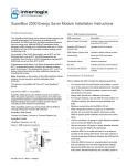
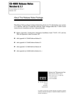
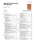
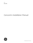
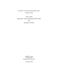
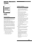
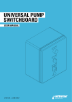
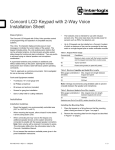
ITI Part No. 60-803 & 60-809
Document Number: 466-1632 Rev. B
September 2000
Installation Instructions
Product Summary
Installation Guidelines
The ITI® SuperBus 2000 2 x 20 LCD (liquid crystal display) Alphanumeric Touchpad gives you complete on-site
system programming and operation control of a compatible
security system (see the section “Specifications”).
❑
A two-line, 40-character display provides visual system
status messages. The display identifies any programmed
location, allowing the user to determine where an alarm,
trouble, or open-sensor condition exists.
Other features include:
❑
❑
❑
❑
Touchpad buttons that light up after the first button
press and remain lit until about 15 seconds after the last
button press.
Adjustable display contrast and backlighting.
Built-in hardwire input (can be supervised with EOL
resistor in SuperBus 2000 panels).
Built-in door, which covers right-side buttons (60-809
only).
SuperBus 2000 Panels vs. SuperBus Panels
SuperBus 2000 panels assign module unit numbers
automatically when the panel is powered up. This
eliminates manually setting unit numbers and the chance of
identical unit number conflicts.
SuperBus 2000 Panels
❑
❑
❑
Table 1: Maximum Bus Devices Per Panel
Panel
62
UltraGard
8
Concord
16
Concord Express
4
❑
❑
❑
❑
❑
Do not exceed the total panel output power when using
panel power for bus devices, touchpads, and hardwired
sensors that require it (see specific panel Installation
Instructions).
Maximum current draw from the touchpad is 120 mA.
Minimum current draw from the touchpad when the
panel is operating only on backup battery is 15 mA.
Mount the touchpad in an environmentally controlled
area (32° to 140° F) (0° to 60° C).
When using the optional touchpad hardwire input, use
only shielded wire (22-gauge or larger), and do not
exceed the maximum wire length limits in Table 2
between the touchpad and detection device.
Note
Shield wire must be connected to earth ground.
Table 2. Hardwire Input Wire Length Limits
Gauge
SuperBus Panels
❑
❑
UltraGard
Concord (software versions 1.0–1.6)
Max. Wire
Length
18 (shielded)
1000 Feet
22 (shielded)
350 Feet
❑
❑
❑
SuperBus® 2000 2 x 20 LCD Alphanumeric Touchpad
Maximum Bus
Devices
Advent
Advent
Concord (software versions 2.0 and newer)
Concord Express
SuperBus panels communicate with SuperBus 2000
modules but require the module unit number to be set
manually. Touchpads automatically default to unit number
001.
For the maximum number of bus devices and
touchpads per panel see Table 1.
When mounting the touchpad back-plate, allow a 1inch clearance on all sides since the touchpad is larger
than the back-plate.
Use 4-conductor, 22-gauge or larger stranded wire from
the touchpad to the control panel.
Follow the wire length limits outlined in the specific
panel Installation Instructions between the touchpad
and control panel.
1
Tools Needed
The following must be observed in UL installations
To mount the touchpad in a gang box:
❑
1.
Separate the mounting bracket from the back-plate by
loosening the two bottom screws and unlatching the
tabs from the mounting slots (see Figure 1).
2.
Line up the gang box mounting holes with the holes on
the gang box (see Figure 2).
3.
Secure the back-plate to the gang box with panhead
screws.
❑
❑
❑
The touchpad hardwire input must not be used for fire
alarm initiating devices.
Only UL-listed devices may be connected to the touchpad hardwire input.
The touchpad hardwire input can be configured for
normally closed or normally open protection devices.
For UL installations with UltraGard and Concord (software versions 1.0–1.6) panels, do not use the touchpad
hardwire input.
Note
Do not overtighten screws or the back-plate may bind
and prevent the touchpad from mounting properly.
Tools Needed
WALL MOUNTING HOLES (X4)
❑
❑
❑
❑
❑
Drill with bits
Screwdrivers
#6 screws and anchors (included)
Panhead screws for a gang box installation
Saw or utility knife for cutting wallboard
BACK PLATE MOUNTING TABS (X3)
Note
Do not use screws larger than #6 or the touchpad will
not seat properly onto the back-plate.
WIRE
ACCESS
HOLE
Installation
The touchpad can be installed on a wall or in a gang box.
To mount the touchpad on a wall:
1.
GANG BOX MOUNTING HOLES (X2)
Separate the mounting bracket from the back-plate by
loosening the two bottom screws and unlatching the
tabs from the mounting slots (see Figure 1).
3101G02B.DS4
Figure 2. Back-Plate and Mounting Holes
2.
Place the back-plate on the wall and mark the four
mounting holes and the wire access hole (see Figure 2).
Be sure to leave a 1-inch clearance on all sides of the
back-plate.
3.
Drill holes and insert appropriate anchors.
4.
Secure the back-plate to the wall with included screws.
Wiring consists of connecting the touchpad wiring harness
to the panel terminals. You may also connect an optional
hardwire sensor to the touchpad hardwire input wires.
5.
Cut a hole in the wall where the wire access hole was
marked to pull your cable through.
Before You Begin
Wiring
MOUNTING SLOTS
OPENING FOR CONNECTOR
1.
Disconnect the panel AC power transformer and
backup battery (turn off power switch on UltraGard
panels).
2.
Run a 4-conductor, 22-gauge wire cable from the panel
to the touchpad location.
3.
Splice the 4-conductor cable wires to the matching colored wires located on the touchpad wiring harness.
Find your panel in the next section for specific wiring
instructions.
CABLE OPENING
LOOSEN BOTTOM SCREWS (X2)
3101G03B.DSF
Figure 1. Touchpad Mounting Slots
2
SuperBus® 2000 2 x 20 LCD Alphanumeric Touchpad
Wiring
Wiring Panels
Concord Systems with software version 2.0 or newerWire a 2K ohm EOL resistor (49-467) in series with
normally closed switches and in parallel with normally
open switches (see Figure 4).
UltraGard Panels
1.
Connect the touchpad wiring to the panel terminals as
shown in Figure 3. Wire multiple touchpads in parallel.
2.
If desired, connect an optional hardwire switch to the
yellow touchpad wires as shown in Figure 3 (unsupervised in UltraGard systems).
Concord Systems with software versions 1.0–1.6 - This
switch must be unsupervised and a resistor must not be
used.
Note
The optional touchpad hardwire input must be added
to panel memory. See the Concord/Concord Express
panel Installation Instructions for setting the
configuration.
Note
The optional touchpad hardwire input must be added
to panel memory. See the UltraGard panel Installation
Instructions or Reference Manual for setting the configuration.
3.
3.
Insert the touchpad wiring harness connector onto the
pins located on the rear of the unit. Make sure the yellow wires are to the left, as shown.
Insert the touchpad wiring harness connector onto the
pins located on the rear of the unit. Make sure the yellow wires are to the left.
PANEL TERMINALS
CONTROL PANEL
DC
OUT
BUS
A
BUS
B
GND
12
13
14
15
OPTIONAL
SWITCH
WITH MAGNET
OPTIONAL
N/O SWITCH
WITH MAGNET
+12V
BUS
BUS
A
BUS
B
3
4
5
6
WHITE
BLACK
WHITE
GREEN
RED
(Not to be used in UL
listed installations)
GND
2K OHM
EOL RESISTOR
GREEN
RED
(Concord 2.0 or later
and Concord
Express panels)
BLACK
Connect Shield
to Earth Ground
Connect Shield To Earth Ground
OPTIONAL
N/C SWITCH
WITH MAGNET
SHIELDED
CABLE
YELLOW
NOT
USED
SHIELDED
CABLE
YELLOW
NOT
USED
TAB
SLOT(3)
TAB
SLOT(3)
TOUCHPAD
WIRING HARNESS
49-430
WIRING HARNESS
49-430
8557155B.DSF
8557148B.DS4
Figure 4. Wiring the Touchpad to Concord and
Concord Express Panels
Figure 3. Wiring the Touchpad to UltraGard Panels
Advent Panels
Concord/Concord Express Panels
1.
Connect the touchpad wiring to the panel terminals as
shown in Figure 4. Wire multiple touchpads in parallel.
2.
If desired, connect an optional hardwire switch to the
yellow touchpad wires as shown in Figure 4.
Concord Express Systems- Wire a 2K ohm EOL resistor (49-467) in series with normally closed switches
and in parallel with normally open switches (see
Figure 4).
SuperBus® 2000 2 x 20 LCD Alphanumeric Touchpad
1.
Splice the touchpad wiring to the panel SuperBus wiring harness as shown in Figure 5. Wire multiple touchpads in parallel.
2.
If desired, connect an optional hardwire switch to the
yellow wires on the touchpad wiring harness. Wire a
2K ohm EOL resistor (49-467) in series with normally
closed switches and in parallel with normally open
switches (see Figure 5).
Note
The optional touchpad hardwire input must be added
to panel memory. See the Advent panel Installation
Instructions for setting the configuration.
3
Mounting the Touchpad
3.
Insert the touchpad wiring harness connector onto the
pins located on the rear of the unit. Make sure the yellow wires are to the left (see Figure 5).
PANEL SUPERBUS
WIRING
HARNESS 49-462
BLACK (GND)
WHITE (BUS B)
GREEN (BUS A)
RED (+12 VDC)
TO ADDITIONAL
SUPERBUS
TOUCHPADS
AND/OR
MODULES
OPTIONAL
N/O SWITCH
WITH MAGNET
these panels, alphanumeric touchpads default to 001. If
desired or necessary, the unit number must be manually
changed.
Guidelines for Assigning Alphanumeric Touchpad
Unit Numbers (Concord panels with software
versions 1.0–1.6 and UltraGard panels)
Use the following guidelines to avoid communication conflicts between bus devices and the panel:
❑
❑
❑
SPLICE
2K OHM
EOL RESISTOR
OPTIONAL
N/C SWITCH
WITH MAGNET
Connect Shield
to Earth Ground
Always start with one touchpad connected to the panel
and make sure it is working properly before connecting
additional touchpads.
Whenever possible, such as in new installations, assign
alphanumeric touchpad unit numbers before beginning
all other panel programming.
Other bus devices with device unit number DIP
switches (ESM, HIM, etc.) must be set to the desired
unit number before applying power and entering
program mode.
Power Up and Bus Communication
SHIELDED
CABLE
YELLOW
Powering Up UltraGard Panels
NOT
USED
TAB
SLOT(3)
TOUCHPAD
WIRING HARNESS
49-430
First Touchpad
1.
Disconnect all bus device wiring from the panel except
for the touchpad location closest to the panel.
2.
Verify that all wiring at the panel and touchpad wiring
harness is correct.
3.
With the panel power switch off, connect the panel battery and plug in the panel AC power transformer.
4.
Set the panel RUN/PROGRAM switch to RUN.
5.
Turn on the panel power switch.
6.
Put the touchpad into the manual configuration mode
by pressing and holding the touchpad D and 6 buttons
until the display shows DA 001 (unit number 001).
7.
Set the panel RUN/PROGRAM switch to PROGRAM
and the display should read PROGRAM MODE.
8.
Verify correct operation by pressing STATUS or
BYPASS. The display should show a different menu
item for each button pressed.
8543109C.DSF
Figure 5. Wiring the Touchpad to Advent Panels
Mounting the Touchpad
1.
Align the slots on the touchpad with the slots on the
back-plate. Insert the mounting tabs into the mounting
slots and press the keypad toward the wall/gang box.
2.
Tighten the two bottom screws.
Setting Touchpad Unit Numbers
Note
In multiple partition systems all new touchpads default
to partition 1. To change partition assignment please
see specific panel Installation Instructions. All
partitions must be disarmed before entering program
mode.
If your installation only calls for one alphanumeric touchpad, you may proceed with other system programming. If
you have more alphanumeric touchpads to connect and
assign device addresses, use the following procedure before
proceeding with any other system programming.
Panels automatically assign or learn the unit numbers of
each bus device upon power up or entering programming
mode. SuperBus 2000 panels (Advent panels and Concord
panels with software version 2.0 or newer) automatically
assign different unit numbers to each SuperBus 2000 module. SuperBus panels (UltraGard panels and Concord panels
with software versions 1.0–1.6) do not automatically assign
different unit numbers to each SuperBus 2000 module. For
4
SuperBus® 2000 2 x 20 LCD Alphanumeric Touchpad
Power Up and Bus Communication
Additional Touchpad
1.
Disconnect the panel AC power transformer, backup
battery, and turn off the power switch.
2.
Connect all bus device wiring to the panel (including
the wiring that was disconnected in step one of the first
touchpad installation), but make sure no new touchpads
are connected to their wiring harnesses yet.
3.
Verify that all wiring at the panel and at the added
touchpad wiring harnesses are correct (but do not
connect any touchpads to their wiring harness).
4.
Apply power to the panel (turn on the power switch).
5.
Set the RUN/PROGRAM switch to PROGRAM.
Existing (previously installed) touchpad(s) display
PROGRAM MODE.
Or—The display shows ENTER CODE or 1-OFF (1 blinking), indicating you need to enter the install code. After
entering the install code, existing touchpads display
PROGRAM MODE.
19. Set the RUN/PROGRAM switch to PROGRAM so the
panel can learn all bus device unit numbers. All touchpads should display PROGRAM MODE.
20. Set the RUN/PROGRAM switch to RUN.
21. At each touchpad, verify correct operation by pressing
STATUS. The display should show the current system
status.
Powering up Concord Panels with Software
Version 2.0 or Newer and Concord Express Panels
1.
Verify that all wiring between the panel and touchpad is
correct.
2.
Connect the panel battery and plug in the panel transformer. Alphanumeric touchpads show “SCANNING
BUS DEVICES,” then a date and time display.
3.
Verify correct operation by pressing ‚. The display
should show the current system status.
Note
Note
After entering the install code to get into program
mode, the panel allows you to switch between RUN
and PROGRAM mode for 1 hour without re-entering
the code.
6.
At an existing touchpad, press BYPASS or STATUS
until the display shows TOUCHPAD OPTIONS.
7.
Press COMMAND and the display shows UNIT
NUMBER.
8.
Press COMMAND; existing touchpads will display
DA 00N (where N is the unit number 0–7). Make a note
of this touchpad unit number.
9.
If after pressing ‚ the touchpad does not display the
current system status, see “Troubleshooting.”
Powering up Concord Panels with Software
Versions 1.0–1.6
First Touchpad
1.
Verify that all wiring between the panel and touchpad is
correct.
2.
Check the unit number DIP switches on all other bus
devices (ESM, HIM, etc.) and make note of their
respective unit numbers.
Check the unit numbers of all other existing touchpads
and write them down.
Note
10. Check the unit number DIP switches on other bus
devices (ESM, HIM, etc.) and make a note of their
respective unit numbers.
Touchpads default to unit number 001 when first
installed. If possible, leave this unit number open. If
unit number 001 is not available, or there are multiple
touchpads installed see the section “Additional
Touchpads” below.
11. Connect the wiring harness to one new touchpad.
12. Put the new touchpad into the manual configuration
mode by pressing and holding the touchpad D and 6
buttons until the display shows DA 001 (unit number
001).
13. Press BYPASS and the display shows ENTER _.
3.
Connect the panel battery and plug in the panel transformer. Alphanumeric touchpads show “SCANNING
BUS DEVICES,” then a date and time display.
4.
Verify correct operation by pressing ‚. The display
should show the current system status.
14. Enter a unit number different from that of the existing
touchpads and any other bus devices in the system by
pressing any of the touchpad buttons numbered 0
through 7.
Note
If after pressing ‚ the touchpad does not display the
current system status, see “Troubleshooting.”
15. Press BYPASS then STATUS to lock in and display
the new unit number for the touchpad.
Additional Touchpads
16. Disconnect this touchpad and repeat steps 11 through
16 for any other new alphanumeric touchpads. Be sure
to disconnect each touchpad after assigning its unit
number.
1.
Verify that all wiring between the panel and touchpad is
correct.
2.
Check the unit number DIP switches on other bus
devices (ESM, HIM, etc.) and make a note of their
respective unit numbers.
3.
Connect the panel battery and plug in the panel transformer. Alphanumeric touchpads show “SCANNING
BUS DEVICES,” then a date and time display.
17. After assigning unit numbers to all the new touchpads,
connect each touchpad to its respective wiring harness.
18. Set the RUN/PROGRAM switch to RUN. All touchpads should display 1 - OFF.
SuperBus® 2000 2 x 20 LCD Alphanumeric Touchpad
5
Deleting Touchpads/Unit Numbers from Panel Memory
4.
At a touchpad, press and hold the D and 6 buttons
(together) for at least 2 seconds. The display should
show DA n, where n is the current unit number (000 –
015) for the touchpad.
Note
At this time, the touchpad is in configuration mode and
no longer communicating with the panel. The system
may immediately indicate a bus failure. Ignore the failure and continue with the procedure. The failure will
clear after the unit number has been successfully
changed.
Note
If the touchpad does not display anything or displays,
“Touchpad Not Enrolled,” see “Troubleshooting.”
Existing Installations
1.
Verify that all wiring between the panel and touchpad is
correct.
2.
Connect the panel battery and plug in the panel transformer.
3.
At an existing touchpad, press 8 to select SYSTEM
MENU.
5.
Press ƒ. The display shows ENTER _.
6.
Enter an unused three digit unit number (000 – 015),
then press ƒ. The display shows DA n, where n is the
new unit number for the touchpad.
4.
Press 0 to select ENTER PROGRAM MODE.
5.
Enter your install access CODE (0123 is default).
7.
Press ‚ to exit from the configuration mode.
6.
8.
Repeat steps 4–8 for all connected alphanumeric
touchpads.
Enter item number 48001 to add bus devices. All
installed devices are automatically added (learned) into
panel memory when DEVICES ADDED is displayed.
7.
Press ‚ once to exit program mode.
8.
New alphanumeric touchpads should display “Security
is Off,” while existing touchpads will display custom or
programmed text.
Note
If the new unit number for the touchpad was previously added (learned) by the panel, communication
between the touchpad and the panel begins immediately. However, if the new unit number for the touchpad has never been added (learned) by the panel,
continue with step nine.
9.
Force the panel to scan bus devices.
❑ For systems where this is the only installed touchpad, remove the panel AC power and backup battery power, then re-apply power.
❑ For systems with more than one touchpad, go to
another system touchpad and enter 8 + installer
CODE (default = 4321) + 0 + 1. The display
shows SCANNING BUS DEVICES, then a date
and time display.
10. Exit the program mode. The touchpad and all other bus
devices should operate correctly and any bus failures
should be cleared.
Note
If the panel still indicates a bus failure the panel may
have previously learned a unit number that is no
longer used by any bus device. Delete the unused unit
number.
Note
If the touchpad does not display anything or displays,
“Touchpad Not Enrolled,” see “Troubleshooting.”
Deleting Touchpads/Unit Numbers
from Panel Memory
Please see the specific Installation Instructions for information on deleting touchpads/unit numbers.
Adjusting Contrast and
Backlighting
Please see the specific panel Installation Instructions or
User’s Manual for more information.
Testing
11. Verify correct operation by pressing ‚. The display
should show the current system status.
CAUTION
Note
If after pressing ‚ the touchpad does not display the
current system status, see “Troubleshooting.”
Powering Up Advent Panels
New Installations
1.
Verify that all wiring between the panel and touchpad is
correct.
2.
Connect the panel battery and plug in the panel transformer. The alphanumeric touchpad should display
“Security is Off,” or any other programmed text.
6
Contact the central monitoring station before activating
alarms to avoid dispatching local police and fire
departments.
Test the touchpad by arming and disarming the system, activating the touchpad panics, bypassing sensors, and by turning lights on and off to verify the correct operation. Refer to
the panel Owner’s Manual for system operating instructions.
Panel Programming
An alphanumeric touchpad must be used to program some
panels. For a complete description of programming commands, refer to the specific panel Installation Instructions.
SuperBus® 2000 2 x 20 LCD Alphanumeric Touchpad
Troubleshooting
Troubleshooting
Tables 3, 4, and 5 describe actions you can take to correct
problems you may experience when connecting bus devices
to each of the different panels.
Table 3: UltraGard Troubleshooting
Problem
All touchpads display
1 - OFF but they don’t
work or won’t enter
program mode.
Action/Solution
1.
2.
The touchpad displays the 1.
message BUS FAIL UNIT
N (N = unit number of
failed bus device).
2.
3.
The panel reports a trouble 1.
condition on the touchpad
loop.
2.
3.
Disconnect all touchpads
except the original. Set the
panel mode switch to
PROGRAM, enter the
install code, and switch
back to RUN.
Assign a different unit number to each touchpad using
the procedure outlined in
this document.
Turn off the panel power
switch. Check the wiring at
all bus devices and correct
where necessary.
Assign a different unit number to each touchpad using
the procedure in this document.
Set the panel mode switch to
PROGRAM then back to
RUN.
Change the unit number on
the new bus device to an
unused unit number. Turn
power OFF then ON. Set the
mode switch to PROGRAM then back to RUN.
Turn off the panel power
switch. Check and correct
the touchpad wiring.
The panel must learn the
hardwire loops again when a
touchpad unit number is
changed.
SuperBus® 2000 2 x 20 LCD Alphanumeric Touchpad
Table 4: Concord and Concord Express
Troubleshooting
Problem
Action/Solution
The touchpad doesn’t 1.
power up (no display
and no beeps when
buttons are pressed). 2.
3.
Check for correct wiring connections at the touchpad and panel
terminals.
Make sure the panel battery is
connected correctly and that the
panel transformer is plugged in.
Make sure the panel transformer
is not plugged into an electrical
outlet controlled by a switch.
Relocate the transformer to an
unswitched outlet if necessary.
The touchpad display 1.
appears blank, but
beeps sound when
buttons are pressed.
Check the touchpad display contrast setting. It may be set to 0 (no
display).
The touchpad displays 1.
a flashing star [*],
indicating a trouble
condition, and the
system doesn’t
2.
respond to commands
from the touchpad.
Check for correct bus wiring connections (green and white wires)
at the touchpad and panel
terminals.
Make sure the touchpad unit
number is set to a number
different from all other bus device
unit numbers. If necessary,
change the touchpad unit number.
(Concord panels with software
versions 1.0–1.6 only).
Table 5: Advent Troubleshooting
Problem
Action/Solution
The touchpad display 1.
seems “stuck” in the
program mode.
Check that the panel is not in the
program mode of operation.
The touchpad displays 1.
“**********”, an
error message, or
appears “dead” and
2.
does not respond to
button presses.
3.
4.
Check that the wiring connector
is plugged into the back of the
touchpad.
Check for incorrect wiring,
opens, or shorts.
Check panel power.
From another touchpad enter
program mode and verify touchpad is enrolled.
The touchpad displays 1.
“Touchpad Not
Enrolled.”
Perform the procedure for “Existing Installations” under the section “Powering up Advent
Panels,” in this document.
7
Specifications
Specifications
Notices
Touchpad/Panel Compatibility:
Touchpad Part No.
Compatible Panel(s)
FCC Part 15 Information to the User
Changes or modifications not expressly approved by Interactive Technologies, Inc. can void the user’s authority to operate the equipment.
60-803-04
Concord, Concord Express
FCC Part 15 Class A
60-809-03
Custom Concord Versions
60-809-03-SEC
Security Pro® UltraGard and Custom
Versions
This equipment has been tested and found to comply with the limits for
a class A digital device, pursuant to part 15 of the FCC rules. These
limits are designed to provide reasonable protection against harmful
interference when the equipment is operated in a commercial environment.
60-803-03
UltraGard and Custom Versions
60-803-01
Advent
Power Requirements: 12 VDC nominal
120 mA maximum (from panel)
Display:
2-line, 40-character (2 x 20),
backlit, alphanumeric liquid crystal
Zone Input:
One supervisable hardwire zone
input
Data I/O:
4-wire ITI SuperBus 2000 auto
addressing digital data bus
Storage Temperature:
-30° to 140° F (-34° to 60° C)
Operating Temperature: 32° to 140° F (0° to 60° C)
Maximum Humidity:
90% (±5%) relative humidity, noncondensing
Listings (see note):
UL 985 Household Fire Warning
System Units
This equipment generates, uses, and can radiate radio frequency energy
and, if not installed and used in accordance with the instruction manual,
may cause harmful interference to radio communications. Operation of
this equipment in a residential area is likely to cause harmful interference in which case users will be required to correct the interference at
their own expense.
FCC Part 15 Class B
This equipment has been tested and found to comply with the limits for
a Class B digital device, pursuant to part 15 of the FCC Rules. These
limits are designed to provide reasonable protection against interference
in a residential installation.
This equipment generates, uses, and can radiate radio frequency energy
and, if not installed and used in accordance with the instructions, may
cause harmful interference to radio communications. However, there is
no guarantee that interference will not occur in a particular installation.
If this equipment does cause harmful interference to radio or television
reception, which can be determined by turning the equipment off and
on, the user is encouraged to try to correct the interference by one or
more of the following measures:
❑
❑
❑
❑
Reorient or relocate the receiving antenna.
Increase the separation between the equipment and receiver.
Connect the affected equipment and the panel receiver to separate
outlets, on different branch circuits.
Consult the dealer or an experienced radio/TV technician for help.
UL 1023 Household Burglar-Alarm
System Units
UL 1610 Central Station BurglarAlarm Units (Commercial
Burglary)
CSFM California State Fire
Marshall
Note
See specific panel Installation Instructions for
complete UL installation requirements for the system
you are installing.
Dimensions:
4.60” x 7.75” x 1.2” (H x W x D)
Chassis Material:
High-Impact ABS plastic
Case Color:
Belgian gray with gray imprints
Interactive Technologies, Inc.
2266 Second Street North
North Saint Paul, MN 55109-2900
T: 651/777-2690
F: 651/779-4890
1-800-777-1415
www.ititechnologies.com
Security
Automation
Fire Protection
Access Control
© 2000 Interactive Technologies, Inc. an Interlogix™ company. Interlogix is
a trademark of Interlogix, Inc. ITI, SuperBus, Advent, UltraGard, and
Security Pro are registered trademarks of Interactive Technologies, Inc.
Concord is a trademark of Interactive Technologies, Inc.
8
SuperBus® 2000 2 x 20 LCD Alphanumeric Touchpad