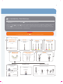
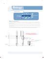
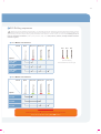
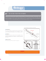
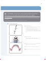
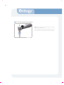
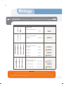
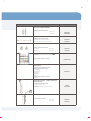
1
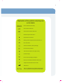
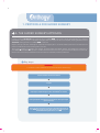
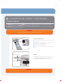
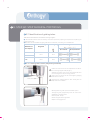
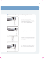
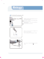
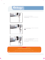
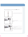
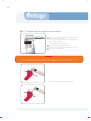
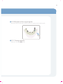
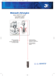
LET US GUIDE YOU
ANTHOGYR Guiding System
ANTHOGYR Guiding System
GE
User manual
SIMPLANT® Pro
2
Thank you for trusting and choosing to use the
ANTHOGYR Guiding System implant solution
for GE .
For your safety and comfort, our products have been designed exclusively on the basis of
data acquired through science and clinical practice.
This document, which is specifically for the ANTHOGYR Guiding System for GE, is
a complement to the GE manual. It is therefore important to read the information concerning the surgical protocol for the GE implant system beforehand.
This document contains the basic information required to use the ANTHOGYR Guiding
System for GE with the complete list of components, through surgical protocols
specific to the system. The document contains a complete list of components ans few key
points for proper use are included as a reminder.
The practitioner should received training provided by DENTSPLY (1) for the SIMPLANT® Pro
software.
Please read the entire GE manual and this document prior to use of the system.
Success is mutual. Our business network and our team of experts are entirely at your
service to provide any additional information that you might need.
The entire Anthogyr team
(1)
DENTSPLY IMPLANT NV, Technologielaan 15, 3001 Leuven, Belgique, +32 16 39 66 11. Simplant® is a
registered trademark of DENTSPLY IMPLANT NV
> Scope
The ANTHOGYR Guiding System for GE is exclusively intended for guided surgery. It enables
the placement of one or more implants with the use of a surgical guide.
3
> Warnings and recommendations
These are the detailed instructions for the different phases of the surgical procedure and prosthetic restoration to be followed with the A
system. A few general aspects specific to the placement of implants will be reviewed for information purposes only. Under no circumstances
is this document on implant and prosthesis-related practice exhaustive and may not give rise to any claim whatsoever.
TRAINING :
The placement of A components concerns only practitioners who have prior training in implant and prosthetic techniques and who are
equipped for these types of procedures. Good knowledge of surgical prosthetic techniques is required for the use of this system. Specific
training is provided and delivered at Anthogyr.
The A surgical and prosthetic system is intended exclusively for use with the original components and instruments, according to the
manufacturer's recommendations. Anthogyr refuses any responsibility for placements that do not conform with this manual, or the use of
implants and prosthetic devices and instruments that are foreign to the system.
Parts are not interchangeable with other implant systems.
Clinical assessment of the patient and the choice of treatment solution are solely the responsibility of the practitioner. The choice of diameter
and length of the implant is up to the practitioner's judgement according to the clinical situation. By the same token, the patient should be
informed of the potential risks involved in the placement of such a device: oedema, hematoma, hemorrhage, periodontal complications, transitory or permanent nerve damage, local or systemic infections and inflammation, bone fracture, loosening or fracture of the implant, dehiscence, aesthetic issues, inhaling or swallowing the device, iatrogenic trauma, etc.
APPARATUS :
Practitioners who use the system are responsible for the monitoring and maintenance required to detect and treat complications, and for
ensuring proper functioning and safety of the device at an appropriate frequency. The references and batch numbers of all components implanted temporarily or permanently should be noted in the patient's medical record. Monitoring and maintenance are a part of the knowledge
that trained practitioners have in the placement of dental implants.
It is also the practitioner's responsibility to define the different settings of his equipment (rotational speed, irrigation flow rate, etc.) according
to each clinical case, and to ensure that it is in good condition before each procedure.
Multiple-use instruments should be cleaned, decontaminated, dried and sterilised prior to every procedure (even with the first use), in conformance with the current protocols in hospitals and clinics. The organisation of the room, the preparation of the operating personnel and the
preparation of the patient (pre-medication, anaesthesia, etc.) should be carried out according to the current protocols and under the practitioner's responsibility.
Under no circumstances can Anthogyr be held responsible for any damage that might be the result of improper manipulation or use. To avoid
swallowing or inhaling small components, it is recommended to secure them outside the mouth with a suture thread. Whenever an instrument is changed, ensure that it is properly secured in the contra-angle or the wrench by applying gentle traction, and that each element is
secured on the transport units outside the oral cavity.
STORAGE :
We pay careful attention to the development of our products and ensure control of the fabrication of all products to be sold. To guarantee their
integrity it is recommended to store them in their original packaging at an ambient temperature between 15°C and 30°C away from moisture
and direct sunlight.
Protect the packaging from dust and do not store in the same room as solvents and/or paint containing solvents or chemical products. The
device should be used before the expiration date indicted on the traceability label.
In case of damage to the packaging (blister pack with seal cover / pouch) or obvious defect when the product is opened, use of the device is
forbidden and the distributor or Anthogyr should be notified of the type of defect and the references and batch numbers of the defective components. The technical specifications in these instructions are provided as an indication and cannot lead to any claim.
The A device is not intended to be used on animals.
Single-use devices should not be reused, or re-sterilised (risk of contamination and risk of alteration in functional surfaces).
The following instructions for use can only be copied or distributed with prior authorisation from Anthogyr. Anthogyr reserves the right to
modify the technical features of the products and to provide developments or improvements to the A system without prior notice.
The A system is not compatible with the other Anthogyr or competing systems.
In case of doubt, the user is responsible for contacting Anthogyr.
This publication of the manual cancels and replaces all prior versions .
4
TABLE OF CONTENT
1. Protocols for guided surgery
6
Explanation of the symbols and pictograms
5
A/ THE GUIDED SURGERY APPROACH
6
B/ SURGICAL PROTOCOLS
7
C/ THE GUIDE FIXATION SCREWS
12
D/ MONT BLANC CONTROL® GUIDED SURGERY CONTRA-ANGLE
13
E/ STEP-BY-STEP SURGICAL PROTOCOLS
14
F/ ANTHOGYR Guiding System - GE KIT
24
G/ PROSTHESIS AND SURGICAL PROTOCOL WITH THE FABRICATION OF A
25
TEMPORARY PROSTHESIS PRIOR TO SURGERY
H/ CLEANING AND STERILISATION
27
I/ DISMANTLING - ASSEMBLY
27
J/ GE IMPLANT REWORKING
27
2. Component references
27
A/ FIXATION INSTRUMENT AND GUIDE REMOVAL
27
B/ ANTHOGYR Guiding System INSTRUMENTS FOR GE
28
5
Explanation of the symbols and pictograms
on the labels
S
Device sterilised by Gamma Ray
O
Serial number of the device
N
Sales reference number of the device
B
V
E
F
g
ù
W
Y
X
Z
k
A
Manufacturing date of the device
Expiration date of the device
Warning: please comply with the instructions for use
Non-sterile device
Autoclave sterilisation, without packaging
Do not sterilise by autoclave
Do no reuse. This device is for single use only.
Protect from light
Do not use if the packaging is damaged
Keep dry at a humidity level between 30% and 70%
30°C
15°C
G/K
Temperature limit between 15°C and 30°C
Manufacturer
Class I or II medical device in compliance with European
directive 93/42/CEE amended by Directive 2007/47/EEC.
6
1. PROTOCOLS FOR GUIDED SURGERY
> A. THE GUIDED SURGERY APPROACH
In order to use the ANTHOGYR Guiding System device for GE, practitioners should have SIMPLANT® Pro software
by DENTSPLY and the patient's computed tomography data. Training in the use of the implant planning software and the
ANTHOGYR Guiding System kit for GE is essential.
Implant planning that takes advantage of computed tomography (CT or CT-scan) enables practitioners to determine the
location of anatomical structures with greater precision.
Three types of guides are available: bone support, mucosal support and dental support. They enable the practitioner to
place G and C implants at predetermined locations and in the right directions and depths. The result obtained is more secure and predictable and can contribute to immediate prosthetic placement.
> Key steps
WARNING !
It is essential to read the SIMPLANT® Pro procedure available at www.dentsply.fr
Patient examination and treatment evaluation
>
CT-scans
>
Importing the computed tomography data in the SIMPLANT® Pro software
>
Planning the implants and guide fixation screws and then ordering the surgical
guide from Dentsply.
>
Surgery with the surgical guide, the instructions, the guide fixation screws, the
GE implant system, the Mont-Blanc Control® for guided surgery and
the ANTHOGYR Guiding System kit for GE
7
> B. SURGICAL PROTOCOLS
The ANTHOGYR Guiding System for GE provides simple surgical protocols.
It ensures rapid and effective familiarisation with the device with perfect control of the implantation. In addition, when combined with the G and C ranges of implants, it enables an exhaustive coverage of treatment indications.
The GE implant system provides a comprehensive range of components enabling perfect adaptation to the different needs related to clinical temporisation in implant practice .
WARNING !
It is recommended to have an GE surgical kit in the operatory theatre.
> B.1 Flap surgery
1
PLACEMENT OF THE
SURGICAL GUIDE
Tightening the guide fixation
screws
6
REMOVAL OF THE
SURGICAL GUIDE
SURGERY IN 2 STEPS
1. Placement of the
cap screw
5-10 N.cm
2
DRILLING
Initial drilling Ø2.0 mm
1 500 rpm
3
OPTIONAL: Fixation of the
surgical guide
Placement of fixation screws
on stable implants.
4
DRILLING
Drilling sequence
1 000 rpm
5
TAPPING (G)
Optional (D1 BONE)
20-25 rpm
SCREWING
Placement of implants
G
C
25 rpm
15 rpm
IMMEDIATE FUNCTIONING
SURGERY IN 1 STEP
Placement of an abutment :
Placement of the
healing cap
5-10 N.cm
or
or
2. Placement of the
healing cap
5-10 N.cm
Temporary
Standard
Multi-Unit Abutment
(standard/angulated)
8
> B.2 Flapless surgery
1
PLACEMENT OF THE
SURGICAL GUIDE
2
3
CUTTING THE GUM
4
REMOVAL OF THE
SURGICAL GUIDE
Hold in position manually
7
8
TAPPING
Optional (D1 BONE)
20-25 tr/min
SCREWING
Placement of implants
G
C
15 rpm
25 rpm
SURGERY IN 2 STEPS
1. Placement of the
cap screw
5-10 N.cm
6
DRILLING
Drilling sequence
1 000 rpm
5
PLACEMENT OF THE
SURGICAL GUIDE
Tightening the guide fixation
screws
DRILLING
Initial drilling Ø2.0 mm
1 500 rpm
9
OPTIONAL: Fixation of the
surgical guide
Placement of fixation screws
on stable implants
REMOVAL OF THE
SURGICAL GUIDE
IMMEDIATE FUNCTIONING
SURGERY IN 1 STEP
Placement of an abutment :
Placement of the
healing cap
5-10 N.cm
or
or
2. Placement of the
healing cap
5-10 N.cm
Temporary
Standard
Multi-Unit Abutment
(standard/angulated)
9
> B.3 Range of implants that are compatible with the ANTHOGYR
Guiding System for GE
G
Ø 3.4 MM
Ø 4.0 MM
1
Ø 4.6 MM
1
8 mm
10 mm
12 mm
14 mm
1
C
Ø 3.4 MM
1
Ø 4.0 MM
1
6,5 mm
6,5 mm
8 mm
8 mm
10 mm
10 mm
12 mm
12 mm
14 mm
14 mm
Ø 4.6 MM
1
8 mm
10 mm
12 mm
14 mm
1
6,5 mm
6,5 mm
8 mm
8 mm
10 mm
10 mm
12 mm
12 mm
14 mm
14 mm
Color identification code for the implant sizes, repeated on the packaging
SINGLE CONNECTION
Ø 2.7
Ø 3.4
Ø 4.0
G
Ø 4.6
Ø 3.4
Ø 4.0
C
Ø 4.6
10
IMPLANT CODING
Sales reference
Implant code
OP : G
OP or
PX
060
080
dd
100 Implant length
lll
120
PX : C
34
140
46
40
Ø implant
> B.4 Drilling depths
During the planning phase, it is recommended to proceed with a "subcrestal positioning of the implant". This positioning enable
better aesthetic management of soft tissues. The surface of the implant ledge is BCP® treated to stimulate peripheral bone
healing at this level.
When the implant is being selected, take into account over-drilling of 1 mm by the drill tips in addition to the subcrestal positioning of 0.5 mm. Over-drilling provides for the storage of bone chips from the self-tapping of the implant and prevents any apical
over-compression.
The use of the drill stop and visual depth marks on the different ancillary instruments ensures the preparation of the implant
site and the predefined positioning of the implant in conformance with the plan made on the Simplant® Pro software.
DRILLING DEPTH = IMPLANT LENGTH +
1mm + SUBCRESTAL POSITIONING (0.5mm)
Implant
length
(mm)
Over-drilling
of the drill
tip
Ø4.0 x 10mm
4mm: height of
the surgical
guide titanium
tube
9 mm
0.5 mm
Theoretical crestal ridge
Subcrestal position
(0.5mm)
1 mm
11
> B.5 Drilling sequences
E
Before the first use and after each procedure, it is essential that all the components are meticulously disinfected, cleaned,
decontaminated, dried and sterilised according to the manufacturer's recommendations. Several uses are possible. For
good viewing of the laser depth marks, good performance and maximum clinical results, we recommend limiting use to 10
times for all cutting instruments (cutters, drills, reamers, taps, etc.). Drills, cutters, reamers, and taps should be used with
external irrigation.
> G DRILLING SEQUENCES
Forets
Ø2.0
Ø2.4 / 3.0
Ø3.0 / 3.6
Ø 3.6 / 4.2
Ø3.4
Ø4.0
Ø4.6
Implants
Optional tapping
Recommended for D1 bone type
Axiom® REG
Ø 3.4 mm
x
x
Axiom® REG
Ø 4.0 mm
x
x
x
Axiom® REG
Ø 4.6 mm
x
x
x
x
Ø2.0
Ø2.4 / 3.0
Ø3.0 / 3.6
Ø 3.6 / 4.2
Axiom® PX
Ø 3.4 mm
x
x
Axiom® PX
Ø 4.0 mm
x
x
Axiom® PX
Ø 4.6 mm
x
x
> C DRILLING SEQUENCES
Forets
Implants
x
RECOMMENDATIONS
Placement of the C implant is contraindicated in type D1 bone.
Do not use the taps when placing C implants
12
> C. THE GUIDE FIXATION SCREWS
Anthogyr fixation screws are made of medical grade titanium alloy. The head is 3.5 mm in diameter, the guiding part, 2 mm
in diameter and the threaded cone-shaped part, a maximum diameter of 1.6 mm under the head. The screws have a mandrel part enabling direct hold in the contra-angle. Available in 3 lengths: 15, 18 and 21 mm, they are self-drilling, selfbreaking and adaptable on contra-angles. During the planning phase, it is important to place the screw as perpendicularly
to the bone as possible. To obtain good stability of the screw plan a 5 mm anchoring in the bone.
1. Self-breaking screw mounted on the mandrel
> ACCESSIBILITY
Breaking zone
The screw is machined in a single block with its grip mandrel which
is self-breaking. Mounted directly on the contra-angle, it enables
difficult areas to be accessed without the risk of falling in the mouth.
Mandrel
Length of the
threaded part
> FLEXIBILITY
Screwing can be entirely carried out with the contra-angle or can be
completed manually with the screwdriver, ref. INGF004. The torque
wrench, ref. INGF005, makes it possible to initiate the breaking of
the mandrel.
Screw
> READY-FOR-USE
The screws are delivered sterile and are for single use.
2. Screw head
3. Breaking groove
WARNING !
When planning, be sure to take into account the direction of the fixation screw so that placement in the oral cavity is possible.
13
> D. THE MONT BLANC CONTROL® GUIDE SURGERY
CONTRA-ANGLE
The ANTHOGYR Guiding System for GE has been specifically designed to function with the Mont Blanc Control®
contra-angle, equipped with the ANTHOGYR Guiding System drill stop (AX laser mark).
The ANTHOGYR Guiding System drill stop has 5 positions that correspond to the 5 heights of the implants that can be used
in guided surgery; 6.5, 8, 10, 12 and 14 mm.
WARNING !
The use of the drill stop is essential for drilling and reaming. The drill stop should not be used for tapping and screwing the
implant: use the visual depth mark that corresponds with the implant.
TO ADJUST THE DRILL STOP :
> Push the lateral slide bar (A) backwards until the drill
stop is released,
> Move the drill stop (B) upwards or downwards to the
notch adapted to the drilling length.
> Release the lateral slide bar (A),
> Ensure that the drill stop is secured by applying mild
traction.
EXAMPLE :
On the drawing, the drill stop is set at the "10 mm" mark.
This configuration is therefore adapted for the placement of
an G or C implant that is 10mm long.
WARNING !
Before using the Mont Blanc control®, please read the Mont Blanc control® contra-angle instructions for use.
14
> E. STEP-BY-STEP SURGICAL PROTOCOLS
> E.1 Identification of guiding tubes
Tubes with various diameters are used with the surgical guide :
> Ø4.2 and Ø5.2 tubes to which the ancillary instrument required for preparing the implant site and placing the
implant can be fitted.
> Ø2.0 tubes can accommodate surgical guide fixation screws and, if necessary, the initial Ø2.0 drill
Diameter of
the implant
Diameter of the gui- Centering ring
ding tube
Centering wrench
Ø 2.0 drills
Ø 2.0/2.4 drills
Ø 3.4
Ø 4.2
Ø 4.2
Ø 5.2
Ø 5.2
Ø 4.0
Ø 4.6
> E.2 Cutting the tissue (flapless protocol)
E
Choose the tissue cutter that corresponds with the diameter of the surgical guide tube (see §E.1).
Assemble the tissue cutter on the contra-angle and move
the contra-angle drill stop to the high position.
Visual limit of depth
E
E
Ensure that it is secured on the contra-angle by applying
mild traction to the tool.
Controlling the stopping depth is done visually with the
depth mark on the mandrel.
Manually place the guide in position and hold in place
Through the guide, progressively move the tissue cutter
downwards to the depth mark
Rotation speed : 50 rpm
Remove the guide and the gum discs
Repeat for each gingival cut
15
> E.3 Placement of the surgical guide using fixation screws
Fit the fixation screw in the contra-angle.
Screw in at 25 rpm until blockage occurs on the guide.
In case of a thick bone, drill the cortex with a Ø2.0 drill
through the fixation screw guiding tube
Drilling at 1,200 rpm with abundant irrigation.
The mandrel part breaks automatically when the torque
reaches approximately 15 N.cm
If the mandrel part of the screw breaks before screwing
is completed, finish screwing with the manual screwdriver by inserting the three pins in the notches located
on the screw head.
If the mandrel does not break when the screw is in
place: insert the torque wrench on the screw head and
restart the motor until breaking is initiated by torsion.
16
> E.4 Initial drill and green drill
Assemble the 2mm or 2.4mm diameter drill (refer to
the drilling sequence, § B.5 )
E
Ensure that it is secured on the contra-angle by applying mild traction to the tool.
Adjust the drill stop to the notch that corresponds with
the implant length.
E
Ensure that the drill stop is secured.
Choose the centering wrench that is adapted to the
diameter of the drill (see §E.1)
Insert the centering wrench in the guide until it blocks
Insert the drill in the wrench and then start the drill
rotation
17
Drill (at 1,200 rpm) with abundant irrigation in a backand-forth motion until blocking occurs.
Stop the drill rotation, then release it from the wrench
WARNING !
Drilling should be done with abundant irrigation.
It is important to remove the bone shavings after drilling.
Do not insert or remove the drill from the centering wrench while it is rotating.
>There is a risk of damaging the tip of the drill and/or the centering wrench and/or the guiding tube which could result in blocking
> E.5 Red, yellow and white drills
ter
Choose the centering ring that is adapted to the diameof the guiding tube (see §E.1) and assemble it on the
drill.
18
Fit the drill into the contra-angle.
Adjust the drill stop to the mark that corresponds with
the implant length.
Insert the assembly (drill + slide bar) in the guide and
then start the drill rotation.
Drill at 800 rpm with abundant irrigation in a back-andforth motion until blocking occurs.
Stop the drill rotation, then remove the guide assembly
(drill + slide bar).
WARNING !
Drilling should be done with abundant irrigation.
It is important to remove the bone shavings after drilling.
Do not insert or remove the drill from the centering ring while it is rotating.
>There is a risk of damaging the tip of the drill and/or the centering ring and/or the guiding tube which could result in blocking
19
> E.6 Tapping (Optional and only for G implants )
Choose the centering ring that is adapted to the diameof the guiding tube (see §E.1) and assemble it on the
tap.
ter
Fit the tap in the contra-angle
E
Raise the contra-angle drill stop to the highest
position .
Tap at 25 rpm to the visual depth mark corresponding
to the length of the implant.
Once the mark is reached, remove the guide tap in the
"reverse" mode.
E
It is important not to use the drill stop due to the risk of
blockage occurring on the guide and deteriorating the
threading made by the tap by its rotation on the spot.
20
> E.7 Transporting the implant into the mouth
E
Aspirate to remove the bone shavings under the guide
at the level of the implant shafts.
The presence of bone shavings can compromise the
placement of the implant.
Fit the mandrel in the contra-angle.
E
E
Raise the drill stop to the highest position.
Controlling the stopping depth is done visually using the
depth mark on the mandrel.
WARNING !
All manipulations are carried out in such a way that direct contact with the external surface of the implant is avoided.
Systematically secure the transfer of the implant against the risk of falling in the mouth
Pick up the implant directly with the contra-angle.
21
> E.8 Insertion of the implant
Set the exit speed of the contra-angle .
Screw the implant on the contra-angle in the implant
shaft to the visual depth mark on the mandrel
Recommended screwing speed :
- G : 25 rpm
- C : 15 rpm
WARNING !
Frequently verify the screwing torque in order not to surpass 80 N.cm.
Do not hesitate to loosen and re-screw to reduce tightening strain.
It is important not to use the ANTHOGYR Guiding System drill stop due to the risk of blockage occuring on the guide and
deteriorating the threading made by the tap by rotation of the implant. It is also possible for the implant to become detached from the mandrel and to continue to advance beyond the intended depth.
The indexed connection of the implant authorises 3 possible orientations for prosthetic components, making it
possible to reduce the manipulation periods and the risks of confusion during dental restoration.
Tri-lobe connection, on the other hand, requires precise anticipated placement of the implant orientation at the
end of rotation.
WARNING !
The implant orientation phase is decisive. It predefines the final orientation of prosthetic components. After osteointegration and bone maturation, the prosthetic orientation is definitive. It is therefore essential to establish the prosthetic treatment plan prior to surgery, especially when the use of prosthetic components that enable angulation is envisaged.
The implant is finally oriented according to the prosthetic solution envisioned and is specific to the component used.
22
> IMPLANT ORIENTATION
Screwing mandrels have 3 surfaces, each one with a visual line mark that corresponds with the implant indexing .
When screwing or unscrewing the implant, orient as close as possible, one of the
marks on the surfaces of the instrument in the appropriate direction, according to
the desired prosthetic restoration and the patient’s mouth.
The mark that is chosen will define the main prosthetic orientation of the components.
ATTENTION !
When orienting the implant, it is important to choose the mark that is closest
to the final orientation in order to preserve the apico-coronal positioning .
> RECOMMENDATION FOR TRI-LOBE POSITIONING
In order to be able to effectively lift the implant axis during the prosthetic phase,
the flat surface of the tri-lobe should be placed in the implant emergence axis.
> E.9 Optional: fixation screw on a stable implant
The fixation screws on an implant make it possible to fix the surgical guide on osteointegrated G or
C implants or when stability is considered to be inadequate by the practitioner.
Manually screw the fixation screws on the implants,
through the guide and without surpassing 15 N.cm.
.
WARNING !
The user should ensure beforehand that the stability of the implant as a support is adequate.
The guide fixation screws are delivered non-sterilised.
They should be cleaned, decontaminated and autoclave sterilised prior to use.
23
> E.10 Removal of the surgical guide
Unscrew the fixation screws and/or the fixation screws on the implant, and then remove the guide .
> E.11 Closing implants
Please refer to the GE manual
24
> F. ANTHOGYR Guiding System KIT FOR GE
WARNING !
Before the first procedure and after each subsequent procedure, it is imperative to disinfect,
clean, decontaminate, dry and sterilise all the instruments and ancillary instruments according
to a precise protocol .
Emplacements
disponibles
TECHNICAL SPECIFICATIONS
The kit is designed with medical grade materials that enable it to withstand thermal disinfection and autoclave sterilisation.
Adjustable protective covers make it possible to change the positioning of the kit in order to optimise the accessibility of
the instruments.
25
> G. OPTIONAL: Prosthesis and surgical protocol with the
fabrication of a temporary prosthesis prior to surgery
Implant analog positioner :
The analog positioner enables the fabrication, prior to surgery, of a master model using the surgical guide with mucosal or
dental support .
This master model can be used to make a temporary prosthesis prior to surgery .
> G.1 In the laboratory
> Assembling analogs
Choose the analog positioner adapted to the diameter of
the guiding tubes of the guide (Ø4.2 or Ø 5.2)
The visual indexation mark on the analog positioner
corresponds with the implant analog indexing
The mark that is chosen will therefore define the orientation of the implant and the indexed prosthetic components .
> Indexation (Optional)
When planning for indexed components, use a small
reamer or a surgical marker to mark the guide .
> Lubricate the interior of the guide to facilitate unmoulding.
Cast the false gum and then the plaster.
> Unmould the master model from the surgical guide .
> Disassemble the analog positioners and then clean the
guide .
26
> G.2 In the operating theater
> Screw the implant in the implant shaft to the visual
depth mark on the mandrel.
When using/planning for indexed components, align one
of the marks on the mandrel with the mark on the guide.
27
> H. CLEANING AND STERILISATION
Please refer to the GE manual .
> I. DISMANTLING - ASSEMBLY
Please refer to the GE manual .
> J. GE IMPLANT REWORKING
Please refer to the GE manual .
2. COMPONENT REFERENCES
> A. FIXATION INSTRUMENTS AND GUIDE REMOVAL
REFERENCES
THE GUIDE FIXATION SCREWS
Medical grade titanium
Length 15 mm
Length 18 mm
Length 21 mm
OPVGS015
OPVGS018
OPVGS021
FIXATION SCREWS ON A STABLE IMPLANT
Medical grade titanium
Ø 4.2 mm
Ø 5.2 mm
OPFG042
OPFG052
SCREWDRIVER
Medical grade stainless steel
INGF004
FIXATION SCREW MANDREL
Medical grade stainless steel
Long mandrel
Short mandrel
INGF001
INGF002
FIXATION SCREW TORQUE WRENCH
Medical grade stainless steel
INGF005
28
> B. ANTHOGYR Guiding System INSTRUMENTS FOR GE
REFERENCES
TISSUE CUTTERS
Medical grade stainless steel
Ø 4.2 mm
Ø 5.2 mm
OPDG042
OPDG052
INITIAL HELICOIDAL DRILLS
Medical grade stainless steel
Helicoidal drill
Helicoidal drill
Ø 2.0 x 21 mm
Ø 2.0 x 25 mm
OPFES20210
OPFES20250
Medical grade stainless steel
Short AGS drill
Long AGS drill
Ø 2.0/2.4
Ø 2.0/2.4
OPFES24210
OPFES24250
Short AGS drill
Long AGS drill
Ø 2.4/3.0
Ø 2.4/3.0
OPFES30210
OPFES30250
Short AGS drill
Long AGS drill
Ø 3.0/3.6
Ø 3.0/3.6
OPFES36210
OPFES36250
Short AGS drill
Long AGS drill
Ø 3.6/4.2
Ø 3.6/4.2
OPFES42210
OPFES42250
HELICOIDAL STEP DRILLS
TAPS (for G only)
Medical grade stainless steel
Ø 3.4 mm implant tap
Ø 3.4 mm implant tap
Ø 3.4 x 21 mm
Ø 3.4 x 25 mm
OPTAS34210
OPTAS34250
Ø 4.0 mm implant tap
Ø 4.0 mm implant tap
Ø 4.0 x 21 mm
Ø 4.0 x 25 mm
OPTAS40210
OPTAS40250
Ø 4.6 mm implant tap
Ø 4.6 mm implant tap
Ø 4.6 x 21 mm
Ø 4.6 x 25 mm
OPTAS46210
OPTAS46250
WARNING !
The components must be disposed of according to the local directives concerning medical waste.
To return components: Anthogyr will refuse any component that might present a risk of infection. Only return components that have been sterilised, with proof of sterility
29
REFERENCES
IMPLANT TIGHTENING MANDREL
Medical grade stainless steel
Ø 4.2 mm
Ø 5.2 mm
OPMAS042
OPMAS052
CENTERING WRENCH
Medical grade stainless steel
4.2/5.2 wrench for Ø 2.0 mm drill
4.2/5.2 wrench for Ø 2.0 / 2.4 mm drill
OPCUS001
OPCUS24
CENTERING RINGS
Medical grade stainless steel
Slide block
Slide block
Ø 4.2 mm
Ø 5.2 mm
OPCOS42
OPCOS52
GUIDED SURGERY KIT
ANTHOGYR Guiding System for GE
Medical grade radel and silicone
Full
IN MOD OPG2
EVOLUTION KIT
Includes the following references :
Medical grade stainless steel
OPFES24210
OPFES24250
OPMAS042
OPMAS052
OPCUS24
Medical grade radel and silicone
4 inserts
KTAGSUP1
MONT BLANC CONTROL® CONTRA-ANGLE FOR
GUIDED SURGERY
Medical grade stainless steel
Complete contra-angle
ANTHOGYR Guiding System drill stop
10403X
10418_SAFE
IMPLANT ANALOG POSITIONERS
Medical grade V titanium
Ø 4.2 mm
Ø 5.2 mm
OPAP042
OPAP052
30
31
063GUIDESYSR-PX_NOT_GB_2015-03
Anthogyr SAS
2 237, Avenue André Lasquin
74700 Sallanches - France
Tél. +33 (0)4 50 58 02 37
Fax +33 (0)4 50 93 78 60
www.anthogyr.fr
Photo credits: Anthogyr - All rights reserved - Non-contractual pictures
Medical devices are intended for use by dentists - Not reimbursed by Social Security - Class IIb - CE0459
Organism notified: LNE/G-MED – Manufacturer: Anthogyr SAS. Please read the instructions in notices and user manuals carefully .