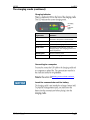
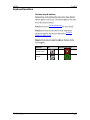
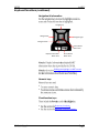
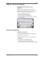
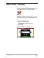
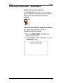
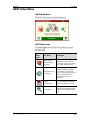
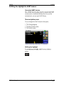
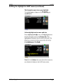
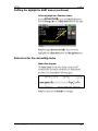
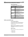
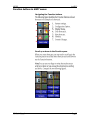
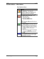
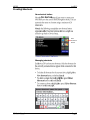
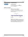
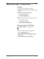
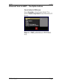
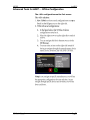
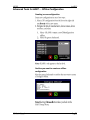
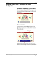
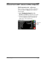
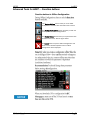
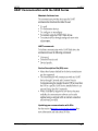
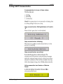
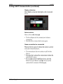
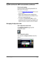
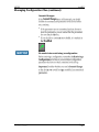
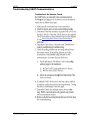
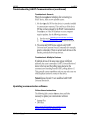
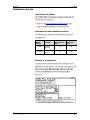
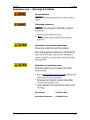
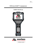
1
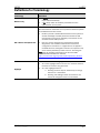
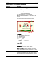
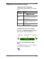
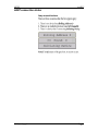
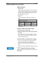
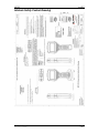
5150 Series HART® Communicator ® 10920 Madison Ave Cleveland · Ohio 44102 1-216-928-1100 1-800- 817-7849 www.Meriam.com User Manual Safety Information Preventing injury Not liable Safety Symbols Safety Symbols Safety Symbols Explaining the symbols This is the Read Instruction Manual symbol. This symbol indicates that you must read the instruction manual. This is the Safety Alert symbol. This symbol indicates a WARNING. Warnings alert you to actions that can cause personal injury or pose a physical threat. Please read these carefully. This is the Safety Glasses symbol. This symbol indicates that you must wear approved safety glasses during the task. This is the Safety Gloves symbol. This symbol indicates that you must wear approved safety gloves during the task. Indicates a potentially hazardous situation which, if not avoided, will result in death or serious injury. Indicates a potentially hazardous situation which, if not avoided, could result in death or serious injury. Indicates a potentially hazardous situation which, if not avoided, could result in minor or moderate injury. Indicates information essential for proper product installation, operation or maintenance. ATEX Documentation ATEX Documentation (continued) Contents User Manual ....................................................1 Low battery level alerts for the XL Battery 26 Safety Information ...........................................2 Low battery level alerts (continued) .......... 27 Safety Symbols ................................................3 The charging cradle ................................... 27 The charging cradle (continued) ............... 28 ATEX Documentation .......................................4 ATEX Documentation (continued) ................5 Trademarks .....................................................9 The charging cradle (continued) ............... 29 Kickstand — useful for viewing the display ..................................................................... 29 HART Communication Foundation ...............9 Loop Communication Jacks & Field-wiring practices ..................................................... 30 Meriam Contact Information ...........................9 Keyboard overview ..................................... 31 Definitions for Terminology ............................10 Definitions for terminology (continued) .....11 Definitions for terminology (continued) .....12 Keyboard functions .................................... 32 Keyboard functions (continued) ................ 33 Keyboard — the on-screen keyboard ....... 34 ISO Latin-1 Character Set .......................... 34 Installing or removing the battery pack .........13 Charging the battery pack ..........................14 Memory System Card ..................................14 Memory System Card (continued)..............15 ISO Latin-1 Character Set (continued) ...... 35 Limited character sets ............................... 36 Limited number of characters ................... 37 Navigating in the screen ............................ 37 5150 Series HART Communicator Overview .16 Navigating the keysets ............................... 38 Touchscreen — System menus..................17 Touchscreen — Keyset #1 ........................ 38 Touchscreen — System menus (continued) .....................................................................18 Touchscreen — Keysets #2–5 .................. 39 Touchscreen — HART menus.....................18 Touchscreen — HART menus (continued) 19 5150 Operating Instructions .........................19 Power key functions ....................................19 Power key functions (continued) ................20 Backlight — reducing intensity ..................21 Backlight — settings for timeout ................22 Navigating the Communicator ................... 40 Navigating the Communicator (continued)41 HART connection status ............................ 42 HART navigation and connection status ....... 43 HART connection status (continued) ........ 44 Green connection bar ................................ 44 HART list of found HART devices ............... 45 Standby — settings for timeout .................23 Main system menus ...................................... 46 Timeout — Backlight and Standby are cumulative ...................................................24 System Setup Menu ................................... 47 The battery pack life ...................................25 Power Setup — System Menu ................... 49 The battery pack life (continued) ...............26 Date/Time Setup — System menu ........... 48 Language Selection — System Menu ........50 Language Selection — Displayed ..............51 Calibrating the touchscreen — System Menu ............................................................52 System Information — System Menu ........53 HART Setup Menu .........................................54 Shifting the highlight in HART menus ........55 Shifting the highlight in HART menus (continued) ..................................................56 Shifting the highlight in HART menus (continued) ..................................................57 Status Line for the connecting device .......57 Advanced Tools for HART — Waiting for the Offline Configuration .................................. 73 Advanced Tools for HART—Indicators in Offline Configuration .................................. 74 Advanced Tools for HART—Indicators in Offline Configuration .................................. 75 Advanced Tools for HART — Function buttons ........................................................ 76 HART Communication with the 5150 Series . 77 Connecting the 5150 to Smart Transmitters with HART technology ................................ 78 Loop resistance > 250 Ω........................... 79 Polling: HART Communication ................... 80 Status Line for the connecting device (continued) ..................................................58 Polling: HART Communication (continued)81 DD files control HART menus .....................58 Specific and Generic HART communication ..................................................................... 82 DD files control HART menus .....................59 Function buttons in HART menus ..............60 Function buttons — Explaining the buttons .....................................................................61 Function buttons — More buttons .............62 Creating Shortcuts ......................................63 Creating Shortcuts — Invalid shortcuts .....64 HART menu path bar ..................................64 Advanced Tools for HART — Two Option buttons .........................................................65 Advanced Tools for HART — Two Option buttons .........................................................66 Advanced Tools for HART — DD Browser ..67 Advanced Tools for HART — View device names and revisions ...................................68 View device names and revisions (continued) ..................................................69 Advanced Tools for HART — Offline Configuration ...............................................70 Advanced Tools for HART — Offline Configuration ...............................................71 Advanced Tools for HART — Offline Configuration ...............................................72 Specific and Generic HART communication (continued) ................................................. 83 Managing Configuration Files.................... 83 Managing Configuration Files (continued) 84 Managing Configuration Files (continued) 85 Managing Configuration Files (continued) 86 Troubleshooting HART Communications .. 87 Troubleshooting HART Communications (continued) ................................................. 88 Updating communicator software ............. 88 Hazardous area use ................................... 89 Hazardous area — Warnings & Cautions . 90 Hazardous area — Warnings & Cautions (continued) ................................................. 91 Returning for repair.................................... 92 Appendices ................................................... 93 Product Specifications ............................... 93 Safety notices ............................................. 94 Waste Electrical and Electronic Equipment (WEEE), Directive 2012/19/EU ............... 95 Spare parts list ........................................... 96 Recommendations for your battery ...........97 Intrinsic Safety Control Drawing .................98 EC Declaration of Conformity .....................99 EC Declaration of Conformity (Intrinsically Safe) .......................................................... 100 Trademarks HART Communication Foundation Meriam Contact Information Meriam Process Technologies Address Meriam Process Technologies 10920 Madison Avenue Cleveland, Ohio 44102 USA Telephone US customers: + 1-800-817-7849 International customers: + 1-216-281-1100 Fax US customers: + 1-216-281-0228 International customers: + 1-216-281-0228 E-mail addresses Website Departments E-mail addresses Return Material Authorization / Service & Repair Department [email protected] Sales [email protected] www.meriam.com Local Meriam Representatives Find a local Meriam representative To find a find local Meriam representative, use this map to find contact information: REP LOCATOR. Definitions for Terminology Terminology Button or key Definitions A button always refers to an area on the screen that you can tap to select functionality. A key always refers to hardware push-buttons on the keyboard that you can press. Manufacturers create HART® compliant Device Description (DD) files that reside on the 5150. You may need to check for updates to the DD files from time to time. DD or Device Description files Highlight DD files “provide a standardized method for host systems to access and display valuable parameters located in field instruments so that the full capability of the device can be accessed via the HART protocol.” DDs are “used to describe such parameters as device diagnostics, multi-variable measurements and device configuration information in a digital format. As applied in the HART Protocol, this digital information is imposed on top of the industry-standard, process control 4–20mA signal.” Note: The two italicized statements come from the HART Communication Foundation’s web site: http://en.hartcomm.org/hcp/tech/dd/aboutprotocol_dds.html This manual uses the word highlight in two ways: 1. As a noun: highlight refers to an icon or a menu line that has the focus on-screen at any given time. 2. As a verb: highlight refers to: a. Pressing the arrow keys or Advance key to change the focus to a new button. b. Pressing and holding a button on-screen for one second to change the focus to a new button. Definitions for terminology (continued) Terminology Definitions Highlights appear in three colors: red, gray, and yellow. A red rectangle appears in System menus: A gray highlight appears in the HART Navigation pane. Highlight colors A yellow border appears in: Selection boxes when an item is selected. The HART Function button pane. The HART menu path bar. Definitions for terminology (continued) Terminology Definitions This manual uses the word select to refer to: Navigating the levels of menus in the communicator. Opening additional screens: o To navigate the communicator’s menu levels. o To view information. o To view additional functions. Performing some task on the communicator. Note: Highlight an on-screen button you want to choose and select it. You may select items by using one of several methods: Navigation numbers Select Navigation shortcuts Touchscreen gestures as you do on a smartphone, such as: Tapping on-screen buttons or icons. Swiping left or right. Scrolling up or down. Navigation keys use: The Arrows and Advance/Switch buttons to highlight a button. The Select button to select the highlighted button. Numeric keys: 1–9 and 0, minus and decimal. These Navigation shortcuts select the function directly. A combination of touchscreen gestures and keys. Note: The Spacebar is used as a shortcut key only on system menus. Since it is directly above the Navigation keys, it offers an easy way to select the connection bar. Standby or sleep This manual uses the word standby mode to describe putting the communicator into an energy-saving mode, where it uses very little power. Some use the word sleep mode instead of standby. Installing or removing the battery pack Installing the battery Don’t over tighten Removing the battery 6-32 screws with 7/64 in. hexagonal socket µSD memory card access Charging the battery pack Charge six (6) hours The charging cradle Memory System Card Uses for the memory card Use only with the 5150 Replace with Meriam Z9P780 µ Memory System Card (continued) Installing & removing battery pack Installing or removing the battery pack Removing the memory card — Replacing the Memory Card 5150 Series HART Communicator Overview Full function HART Diagram of the 5150 Touchscreen — System menus Touchscreen — Display details Touchscreen — Two menu systems Touchscreen — System menus (continued) Touchscreen — System menu Touchscreen — HART menus HART menus appear when connected to HART devices Touchscreen — HART menus (continued) Sample HART menu display 1 2 4 3 5150 Operating Instructions Power key functions Turn on Power key functions (continued) Standby Resume Turn off Backlight — reducing intensity Pressing the Backlight key Reducing intensity improves battery life Backlight intensity at: 20 % 40 % 60 % 80 % While the communicator is on, the battery life is improved by: Up to 80 % Up to 50 % Up to 30 % Up to 12 % Backlight — settings for timeout Changing the timeout setting to save battery life Standby — settings for timeout Change the timeout settings to save battery life Navigating to the Standby timeout settings Timeout — Backlight and Standby are cumulative An example of the cumulative timeouts If… Then… You set the Backlight timeout to 30 seconds You set the Standby timeout to 3 minutes After the communicator is out of the cradle and it has no input for 30 seconds, The communicator reduces the intensity to 10 %. 3 minutes and 30 seconds after the start of the Backlight timeout, The communicator enters Standby mode. The battery pack life Keep charging it 5150 in the charging cradle For portable use Installing or removing the battery pack The battery pack life (continued) Advanced battery fuel gauge Low battery level alerts for the XL Battery Three low battery level alerts Yellow alert Red alert Yellow alert Red alert Final alert Final alert Low battery level alerts (continued) Standby mode and the alerts Reminder: The charging cradle Cradle connection details USB connection to computer Automatically recharges Power connection to AC adapter The charging cradle (continued) Charging indicator Charging LED indicator light Light Status Off Indicates… The communicator has not been correctly inserted or the power is disconnected. Solid Green The battery is fully recharged. Flashing Amber The battery is charging. Solid Amber The battery temperature is out of the charging range. The charging process has been suspended. Flashing Red There is a battery fault. Solid Red There is a charging fault. Connecting to a computer Updating communicator software Insert the communicator not the battery The charging cradle (continued) Not intrinsically safe Hazardous area use section Intrinsic Safety Control Drawing Kickstand — useful for viewing the display Better angle to view the display Loop Communication Jacks & Field-wiring practices Loop Communication Jacks Field-wiring practices Hazardous area use section Intrinsic Safety Control Drawing Keyboard overview Arranged by frequency of use Alphabetic & Decision Upper/lower case toggle Backspace Navigation Enter/Select Information Advance/Switch Numeric Fixed Minus Decimal Power Backlightl Alphabetic keys Keyboard functions Decision keys & buttons Creating Shortcuts Function buttons in HART menus Decision Cancel or Esc Accept Key Touchscreen button Keyboard functions (continued) Navigation & Information Navigate up Navigate left Navigate right Navigate down Enter/Select Menu item Display Information Menu item Enter/Select Menu item Shifting the highlight in HART menus Numeric keys Fixed function keys Power key functions Backlight—reducing intensity Keyboard — the on-screen keyboard Use both the dedicated and on-screen keyboards ISO Latin-1 Character Set ISO Latin-1 character set ISO Latin-1 Character Set (continued) 181 characters on the touchscreen Touchscreen – Keyset #1 Touchscreen – Keysets #2–5 65 characters on the dedicated keyboard Touchscreen buttons appear Limited character sets Buttons and keys are unavailable Lowercase characters are unavailable . Uppercase characters are available. A Caps Lock symbol appears next to the touchscreen Caps Lock button. Limited number of characters Yellow box appears Navigating in the screen Viewing long text Swipe the text to view all of the text line Navigating the keysets Navigating 181 keys Caps Lock Touchscreen — Keyset #1 Diagram of Keyset #1 8 1 2 3 4 5 6 7 Touchscreen — Keysets #2–5 Keyset #2 Keyset #3 (uppercase) Keyset #3 (lowercase) Keyset #4 (uppercase) Keyset #4 (lowercase) Keyset #5 (uppercase) Keyset #5 (lowercase) Navigating the Communicator System Menus Communicator status line 1 2 3 4 Navigating the Communicator (continued) Communicator status line explained Status line Menu Information Function This area displays the system menu. When you see 5150 Field Communicator, you at the top-level menu. Communication Status This displays if HART communication is active, whether there is a primary master (host) on the loop, and if there is a burst mode device active. Battery Status This gives you a quick reference to the current condition of the battery. There is more information available in System Information. Current Time The current time is set by you in the Date/Time Setup Menu Using the bottom row of icons to navigate Go back to the previous menu View the multifunction connection bar Poll for other HART devices Back key – go back to the previous system menu HART connection status Gray connection bars HART navigation and connection status Navigating to the HART Setup Menu Viewing the HART Setup Menu and navigation options HART connection status (continued) Yellow connection bar Green connection bar Restart polling HART list of found HART devices Display a list of devices Main system menus Connected main menu Main menu icons Main System Icons Icon Name Description System Setup Provides access to the system setup menus for changing communicator parameters. HART Setup Provides access to the HART setup menus for changing HART specific parameters. System Information Provides access to information regarding model number, serial number, battery level and so on. System Setup Menu System Setup menu icons Descriptions of Setup icons Setup Menu Icons Icon Name Description Date & Time Setup You can set the current date and time for timestamps on files and system indicators. Power Management You can adjust settings for power usage (backlight and standby timers). Language You can select the preferred language. Touchscreen Calibration You can calibrate the touchscreen. Date/Time Setup — System menu Date/time Setup Date/Time Menu Icons Date/Time Menu Icons Icon Name Description Date You can adjust the system day, month and year. Time You can adjust the system minutes and hour. 12-hour or 24-hour mode You can choose 12-hour or 24-hour time for display. Power Setup — System Menu Power Setup Menu Power Setup Icons Power Setup Menu Icons Icon Name Description Backlight Timeout You can set the timeout to automatically reduce the backlight to the minimum setting (10 %) during periods of inactivity. Standby Timeout You can set the timeout to automatically switch the system to standby mode during periods of inactivity. Language Selection — System Menu Display available languages Select your language Language Selection — Displayed Turn off and Turn on New language displayed Some screens not translated Calibrating the touchscreen — System Menu Begin calibrating the touchscreen Accept the new settings or keep the old settings System Information — System Menu View status details about the communicator System Information HART Setup Menu HART Setup Menu HART Setup icons HART Menu Icons Icon Name Description HART Polling Address Range Selection You can select a range of addresses to poll or select a tag or long tag to use in polling for a HART enabled device. Setup HART Tag For Display You can select which tag to display on HART connection bar. Choices are tag or long tag. If a long tag does not exist on the connected device, a short tag will always be displayed. Offline Configuration You can configure an offline device. See Advanced Tools DD Browser You can review all DDs on the 5150 by manufacturer, device revision level, and DD revision level. Shifting the highlight in HART menus Connected HART devices Three navigation panes Shifting the highlight Shifting the highlight in HART menus (continued) The Navigation pane has a gray highlight Yellow highlight on the menu path bar Shifting the highlight in HART menus (continued) Yellow highlight on a Function button Status Line for the connecting device Status line diagram Status Line for the connecting device (continued) Status Line descriptions Status Line Part Connected HART Device Function This displays the model name of the HART device currently communicating with the 5150 Series communicator HART Tag This displays the tag information returned from the HART device. This alternates red and gray when there is active communication. This remains gray when there is no communication. HART Beat Other active HART comm This displays other HART devices that are active in the HART loop. “P” indicates a Primary Master. “B” indicates a Bursting Slave Device in burst mode. Battery Level This displays the remaining charge (green) that battery pack has. Current Time Time of day. DD files control HART menus Device Description (DD) files Menu Line Items DD files control HART menus Parameter status column The —MORE— menu item Function buttons in HART menus Navigating the Function buttons 1 5 2 6 3 7 4 Scroll up or down in the Function pane Function buttons — Explaining the buttons Explaining the Function buttons Buttons Function The System Settings button returns you to the system menus. The HART connection is not dropped when you select this button. Select the green HART connection bar to return to the HART menus when you have finished using the system menus. Note: Some system setting changes may require the HART connection to be re-established before the changes will occur. The New Shortcuts button allows users to create shortcuts to HART menus. The Select Configuration Option button displays two icons: The first is the Not ready button. It looks like a folder. It displays four options: o Retrieve Configuration (not active). o Store Configuration (not active). o Review Configuration (active). o Delete Configuration (active). The second is the Ready button. It looks like folder that has two arrows. It displays four options: o Retrieve Configuration (active). o Store Configuration (active). o Review Configuration (active). o Delete Configuration (active). Function buttons — More buttons More Function buttons — Creating Shortcuts New shortcut button New shortcuts button Managing shortcuts Creating Shortcuts — Invalid shortcuts An invalid shortcut HART menu path bar Structure of the menu path bar Intermediate menu Online menu (Root menu) Current menu Advanced Tools for HART — Two Option buttons Two Options Three ways to navigate in the DD Browser Advanced Tools for HART — Two Option buttons Cancel button in DD Browser Advanced Tools for HART — DD Browser Use the DD Browser to view a list of manufacturers Navigate lists in a complete circle Advanced Tools for HART — View device names and revisions View a list of device names View device names and revisions (continued) View a list of device revisions The right side of the screen (gray area) Advanced Tools for HART — Offline Configuration Offline Configuration navigation Two ways to use the offline configuration Advanced Tools for HART — Offline Configuration The <All> configurations on the first screen Advanced Tools for HART — Offline Configuration Creating a new configuration Confirm you want to create an offline configuration Advanced Tools for HART — Waiting for the Offline Configuration Wait while the 5150 initiates the offline device Blue connection bar Offline icon Advanced Tools for HART—Indicators in Offline Configuration Question marks and default variables in the DD file Advanced Tools for HART—Indicators in Offline Configuration Modified parameters alert – yellow arrow Configuration Options button Advanced Tools for HART — Function buttons Function buttons in Offline Configuration The System Settings button takes you to the HART Setup Menu. Press the Blue connection bar to return. The Configuration Options button provides you with the same options as online configurations. The Display Status button alerts you to parameters with undetermined values. See the figure below. The Cancel button stops the Offline Configuration and returns to the HART Setup Menu with no offline configuration device displayed. — — HART Communication with the 5150 Series Maintain field devices HART commands Device Description file (DD) uses Updating your communicator with DDs Updating communicator software Connecting the 5150 to Smart Transmitters with HART technology Banana Jacks Wiring diagram: Loop resistance < 250 Ω Loop resistance > 250 Ω Wiring diagram: loop resistance > 250 Ω Polling: HART Communication A communicator is in one of three states: Gray connection bar: Polling Address or Found is “0” Gray connection bar: Initiating Gray connection bar: no actions Yellow connection bar: Number of Devices Found Polling: HART Communication (continued) Display all devices Select a device Green connection bar: connected Specific and Generic HART communication Find specific devices Find generic devices Generic starts automatically Specific and Generic HART communication (continued) Generic mode running Polling: HART Communication Managing Configuration Files The Configuration Option button Four configuration options Managing Configuration Files (continued) First Option: Retrieve a device configuration Second Option: Store files to µSD Memory Card Managing Configuration Files (continued) Configuration dialog boxes µ Third option: Review Configuration Fourth option: Delete Configuration Managing Configuration Files (continued) Commit Changes Be careful when retrieving a configuration Troubleshooting HART Communications Troubleshoot: No Devices Found Connecting the 5150 to Smart Transmitters Troubleshooting HART Communications (continued) Troubleshoot: Generic Updating communicator software http://www.hartcomm.org/ Troubleshoot: Multiple Devices Updating communicator software Follow these instructions http://www.5150update.com/Installing Field Communicator Manager Software.pdf Hazardous area use Intrinsically Safe Model Intrinsic Safety Control Drawing Hazardous and non-hazardous locations Model Number Location Non-hazardous Area 5150 General Purpose Yes NO 5150X Intrinsically Safe Yes Yes Example of a name plate Hazardous Area Hazardous area — Warnings & Cautions No substitutions Important Preventing explosions important Never Restrictions on electrical connections Restrictions in hazardous areas Intrinsic Safety Control Drawing US Customers International customers 1-800-817-7849 + 1-216-281-1100 Hazardous area — Warnings & Cautions (continued) Double check the Intrinsic Safety Control Drawing Intrinsic Safety Control Drawing Returning for repair First — Request a Number In the event that a 5150 Series requires service and must be returned for repair, please contact Meriam using one of the methods listed in the following table to request a Return Material Authorization (RMA) number: Method Information Website: http://www.meriam.com/resources/service-repairauthorization/ Complete information online and submit the form. If you printed and completed the Service & Repair Authorization form, then fax it to: Fax: US Customers + 1-216-281-0228 International customers + 1-216-281-0228 We need the following information in the email: E-mail: Look on the 5150 Series label to find the Model number & the Serial number. Give a brief description of the problem. Send the e-mail to: [email protected] Return Material Authorization Do not send any unit for repair unless you contacted Meriam for a Return Material Authorization (RMA) number. Important: If you have not received this number and clearly marked it on the package being shipped back, we will return the unit at your expense. The Meriam Service & Repair Department will provide you with this number when you complete the website form, fax or e-mail your information. An RMA number must accompany all incoming packages to insure proper tracking, processing, and repair work. Questions? Call Meriam US Customers + 1-800-817-7849 International customers + 1-216-281-1100 Ship the box to Meriam Process Technologies 10920 Madison Avenue Cleveland, Ohio 44102 USA Appendices Product Specifications BASE UNIT: 11.9 in. L, 5.6 in. W (at display), 2.50 in. W (at handle), 1.9 in. D. (30.2 cm L, 14.2 cm W (at display), 6.3 cm W (at handle), 4.8 cm D) PC/ABS alloy plastic case with shock absorbing bumpers, rated IP51, 2.1 lbs. including battery. Passes one meter drop test onto concrete DISPLAY: 4.3-in. widescreen backlit TFT color touchscreen display with 480 x 272 WQVGA pixel resolution. POWER: Li-ion battery pack, 3.6 volts nominal. 1.5A charging cradle. 100-240Vac, 50/60Hz input. BATTERY LIFE (Approximate): 10 hours continuous use at the 100 % backlight setting (typical) TEMPERATURE SPECIFICATIONS: Storage: –40° F to 140° F (–40° C to 60° C) Operating: 14° F to 122° F (–10° C to 50° C) Charging: 50° F to 104° F (10° C to 40° C) CONNECTIONS: Standard banana jacks (¾ in. center) for HART communication. Communication (serial cable to computer port) / Battery charging. Connection via charging cradle. APPROVALS: 5150X (ATEX/I.S.) ATEX Intrinsically Safe cULus Listed Entity parameters: εΧ II 1 G; Ex ia IIC T4 Ga Intrinsically Safe, Exia Class I, Div. 1 Groups A, B, C, D: T4 –10º C < Ta < +50º C IECEx UL 13.0004 Pi = 1.25W, Ii = 200mA, Ci = 0, Li=0, Vi=30V, Um (USB) = 5V, Um (battery) = 5V APPROVALS: 5150 (general purpose) MEMORY: Dedicated µSD flash memory card for 5150 Series application software, DD and configuration storage. Safety notices Avoid intense heat Electrical shock If there is any… Deformation, Cracks, Damage to the charging cradle, Damage to the power cord, or Damage to the power adapter. Don’t disassemble or modify No extension cords Important: Then… Unplug the charging cradle. Never use it again. Waste Electrical and Electronic Equipment (WEEE), Directive 2012/19/EU European Union only Important European Union Product Category US government agencies www.epa.gov Other countries Spare parts list Meriam Part numbers Meriam Contact Information Part Number Description ZA90052900014 HART Test Lead Kit — included with unit. This is the standard banana plugs, minigrabbers, 250 Ω shunt resistor. ZA36821 Standard size 250 Ω shunt resistor — included with unit. This is required for HART low resistance loops. Z9P790 Soft carrying case — included with unit. This is a custom, soft case with adjustable shoulder strap and HART lead compartment. Z9P791 Hand strap — included with unit. Z9A820-3 5150 Series Lithium Ion Battery Pack — included with unit. Z9A879 5150 Series battery charging kit — included with unit. 100 – 240 Vac, 50/60 Hz. It includes charging cradle, power cord, and USB cable. Z9P802 USB cable: Type A to B. It is 2 m length (6.60 feet) — included with unit. You must have this to update the unit. Z9P822 5150 Series battery charging power cord — included with unit. Z9P823 7/64 in. Hex key wrench — included with unit. This fits the battery pack screws. Z9P780 5150 Series µSD system memory card — included with unit. The 5150 software is installed on it. Z9A1100 Kickstand Replacement Kit — included with unit. Recommendations for your battery Make it last longer: Note: Note: Temperature Specifications °F - Fahrenheit °C – Celsius Storage –40 to 140 –40 to 60 14 to 122 –10 to 50 Operating Storing your 5150 for more than 30 days? Two factors affect your battery’s life in storage Note: Important: Intrinsic Safety Control Drawing EC Declaration of Conformity EC Declaration of Conformity (Intrinsically Safe)