1
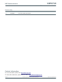
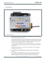
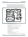
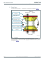
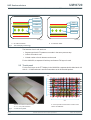
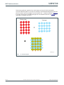
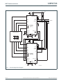
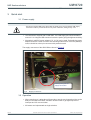
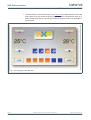
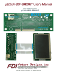
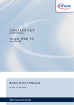
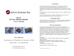
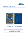
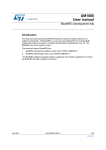
UM10720 User manual for the TFT touch demo board OM11058 Rev. 1 — 25 June 2013 User manual Document information Info Content Keywords OM11058, PCA8885, PCF8885, capacitive touch sensor, touch on TFT, touch foil Abstract The OM11058 demonstrates the capabilities of the PCA8885 and PCF8885 for touch on display by using a double-sided ITO touch foil with a diamond matrix and two ICs cascaded for an 8 8 resolution on a 7 inch TFT display UM10720 NXP Semiconductors User manual for the TFT touch demo board OM11058 Revision history Rev Date Description v.1 20130625 new user manual, first revision Contact information For more information, please visit: http://www.nxp.com For sales office addresses, please send an email to: [email protected] UM10720 User manual All information provided in this document is subject to legal disclaimers. Rev. 1 — 25 June 2013 © NXP B.V. 2013. All rights reserved. 2 of 16 UM10720 NXP Semiconductors User manual for the TFT touch demo board OM11058 1. Introduction Fig 1. OM11058 demo board Interactive user interfaces like in smartphones have become a must also in automotive, industrial and white goods control units. Unlike smartphones where multi-touch, drag and drop and zooming features are used, the dedicated user interfaces in, for instance climate control or washing machine, only have to be a replacement of mechanical buttons by on-display touch buttons. Accordingly, the hardware- and software-design should be as simple as possible. The PCA8885 and PCF8885 are providing very suitable features for easy configuration, connection of various numbers of channels, optimization of sensitivity and sampling for each application. The purpose of the OM11058 is to demonstrate the capabilities of the PCA8885 and PCF8885 for touch displays. 1.1 The PCA8885 and PCF8885 multi-channel capacitive proximity sensors The PCA8885 and PCF8885 are capacitive 8-channel touch and proximity sensors detecting changes in capacitance on remote sensing plates. Changes in the static capacitances (as opposed to dynamic capacitance changes) are automatically UM10720 User manual All information provided in this document is subject to legal disclaimers. Rev. 1 — 25 June 2013 © NXP B.V. 2013. All rights reserved. 3 of 16 UM10720 NXP Semiconductors User manual for the TFT touch demo board OM11058 compensated using continuous auto-calibration. Remote sensing plates (for example, conductive foils) can be connected to the IC. The eight input channels operate independently of each other. There is also a built-in option for a matrix arrangement of the sensors: interrupts are generated only when two channels are activated simultaneously, suppression of additional channel outputs when two channels are already active. 7(67 &/.B,1 26&,//$725 &/. &/.B287 9'' 7,0,1* &21752/ 7$ 92/7$*( 5(*8/$725 9'',175(*' 7$WR7$ WGFKUHI 7(67 &21752/ *(1(5$725 $ ,1 6&/ &+$11(/ O&,17(5)$&( &3& 6'$ ,1 &+$11(/ ,17B,1 &3& 287 WR 287 6(16 ,1 6<67(0 &21752/ ,17 6/((3 3&$ 3&) &+$11(/ &3& DDD 966 Fig 2. Block diagram of PCA8885 and PCF8885 Key features of the PCA8885 and PCF8885 are: • • • • • • • • • • • • UM10720 User manual Eight independent channels (can be configured as 4 4 matrix) I2C-bus interface One subaddress to enable up to 64 keys, cascading 2 devices Sleep mode, activated via I2C-bus or external input Three sensing modes: one key, two keys and n-keys Two event handling modes: direct and latching mode Adjustable scan frequency Channel masking feature Fast start-up mode Operating temperature range (Tamb = 40 C to +85 C) TSSOP28 and SO28 package available PCA8885: AEC-Q100 compliant for automotive and harsh environment applications All information provided in this document is subject to legal disclaimers. Rev. 1 — 25 June 2013 © NXP B.V. 2013. All rights reserved. 4 of 16 UM10720 NXP Semiconductors User manual for the TFT touch demo board OM11058 2. Description and technology of OM11058 The OM11058 block diagram is shown in Figure 3. 13 x 21 line diamond structure on two layers 7” TFT display Interconnection board for FPC OM11056 2 x PCA8885 evaluation board LPC1788 Development kit UM10720_01 Fig 3. UM10720 User manual Block diagram of the OM11058 All information provided in this document is subject to legal disclaimers. Rev. 1 — 25 June 2013 © NXP B.V. 2013. All rights reserved. 5 of 16 UM10720 NXP Semiconductors User manual for the TFT touch demo board OM11058 2.1 Display layers The basic building elements of - for example - a passive LCD are shown in Figure 4. Segments: transparent Polarizer opaque Display glass - Top Segments – Top ITO Liquid crystal molecules Common – Bottom ITO Polarizer incident light UM10720_03 Fig 4. LCD layers The touch sensor pads can be placed on the same layer as the display ITO as an interleaved pattern (in-cell) or on top of the display glass, sandwiched under the polarizer (on-cell), see Figure 5. UM10720 User manual All information provided in this document is subject to legal disclaimers. Rev. 1 — 25 June 2013 © NXP B.V. 2013. All rights reserved. 6 of 16 UM10720 NXP Semiconductors User manual for the TFT touch demo board OM11058 Polarizer ITO Layer Touch Polarizer Glass Glass ITO Layer Segment + Touch ITO Layer Segment Liquid Crystal Liquid Crystal UM10720_05 UM10720_04 a. On-cell touch stack Fig 5. b. In-cell touch stack Touch display technology The features of an in-cell stack are: • Segment and touch ITO patterns are made in the same process step • Lower LCD module cost • Limited number of touch buttons can be made For the OM11058, a separate foil with top and bottom ITO layers is used. 2.2 Touch panel For the touch layer on the TFT display in the OM11058, a separate double sided touch foil with 21 13 diamond matrix structure was taken as an off-the-shelf product. IC#1 7 6 5 4 3 2 1 0 7 6 5 4 3 2 1 0 IC#2 Available vertical and horizontal lines: 13 21 = 273 points resolution Fig 6. 8 8 lines provide 64 touch buttons of which 16 are used for the OM11058 7- inch touch panel UM10720 User manual All information provided in this document is subject to legal disclaimers. Rev. 1 — 25 June 2013 © NXP B.V. 2013. All rights reserved. 7 of 16 UM10720 NXP Semiconductors User manual for the TFT touch demo board OM11058 If the sensor pads are organized in a matrix layout such as a foil with horizontally connected diamond pads on one side and vertically connected diamond pads on the other side, the sensor inputs of a single IC can be used for a 4 4 matrix as shown in Figure 7. For larger matrices two PCA8885 packages can be cascaded as shown in Figure 8 to locate the XY position of a touch. Bottom layer Top layer + UM10720_08 Fig 7. UM10720 User manual 4 4 matrix layout All information provided in this document is subject to legal disclaimers. Rev. 1 — 25 June 2013 © NXP B.V. 2013. All rights reserved. 8 of 16 UM10720 NXP Semiconductors User manual for the TFT touch demo board OM11058 VDD 100 nF IN[0] VDD VDD(INTREGD) TEST RPU RPU 100 nF SCL SDA SLEEP IN[1] to MCU IN[2] (1) A0 IN[3] PCA8885 (primary) IN[7] CLK_IN CLK_OUT (2) INT_IN SENSOR MATRIX INT CPC[0] CPC[7] VSS VDD 100 nF 100 nF CCPC[7] CCPC[0] VDD 100 nF IN[0] TEST VDD VDD(INTREGD) 100 nF SCL SDA SLEEP IN[1] (1) IN[2] A0 IN[3] PCA8885 (secondary) IN[7] CLK_IN CLK_OUT INT INT_IN CPC[0] 100 nF CCPC[0] Fig 8. CPC[7] (3) VSS 100 nF CCPC[7] 013aaa581 Cascaded application diagram UM10720 User manual All information provided in this document is subject to legal disclaimers. Rev. 1 — 25 June 2013 © NXP B.V. 2013. All rights reserved. 9 of 16 UM10720 NXP Semiconductors User manual for the TFT touch demo board OM11058 3. Quick start 3.1 Power supply CAUTION This device needs a USB source that is able to handle 2.5 A. Ensure that the USB supply connection is able to provide this amount of power. Otherwise, damages may occur. • The OM11058 is shipped with a USB cable. The USB supply port should be able to source 2.5 A. Using the USB connector is also the option giving the highest sensitivity. • Alternatively a AC/DC power adapter (5 V, >2.5 A) can be used. Preferably the power adapter should be a linear converter. If a switching mode AC/DC converter (SMPS) is used, it should be a three-pin connector with protective earth. The supply connectors of the OM11058 are shown in Figure 9. USB or power jack for supply connecon Fig 9. Supply connectors 3.2 Operation • When powering up, it takes about 30 seconds to get the touch operational due to the delays in the start of the MCU evaluation board in order to get right sequence of interrupts and I2C communication. • All buttons are implemented as single switches. UM10720 User manual All information provided in this document is subject to legal disclaimers. Rev. 1 — 25 June 2013 © NXP B.V. 2013. All rights reserved. 10 of 16 UM10720 NXP Semiconductors User manual for the TFT touch demo board OM11058 • The temperature up and down buttons (see Figure 10) are implemented as touch and hold buttons. If the touch lasts longer than half a second, the temperature steps up or down 14 steps with 200 ms intervals (the number of steps and interval is adjustable in the firmware). Fig 10. Touch display of the OM11058 UM10720 User manual All information provided in this document is subject to legal disclaimers. Rev. 1 — 25 June 2013 © NXP B.V. 2013. All rights reserved. 11 of 16 UM10720 NXP Semiconductors User manual for the TFT touch demo board OM11058 4. Waterproof touch display with ultra fast auto-calibration • A liquid droplet or thick film of condensation is continuously compensated. (See http://www.youtube.com/watch?v=K7RZM8fPVlw). • A significant water droplet or a water splash creating a film of water over a touch display or a capacitive touch control panel results in increased capacitance. However the self-capacitance measurement technique is the most efficient way of adaptability.‘(See http://www.youtube.com/watch?v=CT6acNtj-5c). • Another mechanism for capacitance change could be a magnetic or piezoelectric haptic feedback generator changing the input capacitance to different levels after every event as well as mechanical deformations. This is also automatically compensated. 4.1 Ensuring reliable operation • Regardless of what causes a capacitive event, the most important action is to bring the capacitive sensor back to a functional state after every event: be it a real touch, a water droplet, a haptic feedback event or a mechanical movement. • Fast auto-calibration after every touch and action ensures that the sensor is always ready for the next touch (fast auto-calibration runs 50 times faster than normal auto-calibration). This procedure takes just a few milliseconds (1 ms to 5 ms) and the sensor IC enters operation mode as soon as the fast calibration is completed, without any further intervention from the microcontroller. UM10720 User manual All information provided in this document is subject to legal disclaimers. Rev. 1 — 25 June 2013 © NXP B.V. 2013. All rights reserved. 12 of 16 UM10720 NXP Semiconductors User manual for the TFT touch demo board OM11058 5. References UM10720 User manual [1] UM10370 — User Manual for the PCF8883 Evaluation Kit OM11055; user manual [2] UM10505 — OM11057 quick start guide; user manual [3] UM10664 — PCA8885 and PCF8885 evaluation board OM11056; user manual [4] UM10711 — Slim proximity touch sensor demo board OM11052; user manual [5] PCA8885 — Capacitive 8-channel touch and proximity sensor with auto-calibration and very low power consumption; data sheet [6] PCA8886 — Dual channel capacitive proximity switch with auto-calibration and large voltage operating range; data sheet [7] PCF8883 — Capacitive touch/proximity switch with auto-calibration, large voltage operating range, and very low power consumption; data sheet [8] PCF8885 — Capacitive 8-channel touch and proximity sensor with auto-calibration and very low power consumption; data sheet All information provided in this document is subject to legal disclaimers. Rev. 1 — 25 June 2013 © NXP B.V. 2013. All rights reserved. 13 of 16 UM10720 NXP Semiconductors User manual for the TFT touch demo board OM11058 6. Legal information 6.1 Definitions Draft — The document is a draft version only. The content is still under internal review and subject to formal approval, which may result in modifications or additions. NXP Semiconductors does not give any representations or warranties as to the accuracy or completeness of information included herein and shall have no liability for the consequences of use of such information. 6.2 Disclaimers Limited warranty and liability — Information in this document is believed to be accurate and reliable. However, NXP Semiconductors does not give any representations or warranties, expressed or implied, as to the accuracy or completeness of such information and shall have no liability for the consequences of use of such information. NXP Semiconductors takes no responsibility for the content in this document if provided by an information source outside of NXP Semiconductors. In no event shall NXP Semiconductors be liable for any indirect, incidental, punitive, special or consequential damages (including - without limitation - lost profits, lost savings, business interruption, costs related to the removal or replacement of any products or rework charges) whether or not such damages are based on tort (including negligence), warranty, breach of contract or any other legal theory. Notwithstanding any damages that customer might incur for any reason whatsoever, NXP Semiconductors’ aggregate and cumulative liability towards customer for the products described herein shall be limited in accordance with the Terms and conditions of commercial sale of NXP Semiconductors. Right to make changes — NXP Semiconductors reserves the right to make changes to information published in this document, including without limitation specifications and product descriptions, at any time and without notice. This document supersedes and replaces all information supplied prior to the publication hereof. Suitability for use — NXP Semiconductors products are not designed, authorized or warranted to be suitable for use in life support, life-critical or safety-critical systems or equipment, nor in applications where failure or malfunction of an NXP Semiconductors product can reasonably be expected to result in personal injury, death or severe property or environmental damage. NXP Semiconductors and its suppliers accept no liability for inclusion and/or use of NXP Semiconductors products in such equipment or applications and therefore such inclusion and/or use is at the customer’s own risk. Applications — Applications that are described herein for any of these products are for illustrative purposes only. NXP Semiconductors makes no representation or warranty that such applications will be suitable for the specified use without further testing or modification. Customers are responsible for the design and operation of their applications and products using NXP Semiconductors products, and NXP Semiconductors accepts no liability for any assistance with applications or customer product design. It is customer’s sole responsibility to determine whether the NXP Semiconductors product is suitable and fit for the customer’s applications and products planned, as well as for the planned application and use of customer’s third party customer(s). Customers should provide appropriate design and operating safeguards to minimize the risks associated with their applications and products. NXP Semiconductors does not accept any liability related to any default, damage, costs or problem which is based on any weakness or default in the customer’s applications or products, or the application or use by customer’s third party customer(s). Customer is responsible for doing all necessary testing for the customer’s applications and products using NXP Semiconductors products in order to avoid a default of the applications and the products or of the application or use by customer’s third party customer(s). NXP does not accept any liability in this respect. Export control — This document as well as the item(s) described herein may be subject to export control regulations. Export might require a prior authorization from competent authorities. Evaluation products — This product is provided on an “as is” and “with all faults” basis for evaluation purposes only. NXP Semiconductors, its affiliates and their suppliers expressly disclaim all warranties, whether express, implied or statutory, including but not limited to the implied warranties of non-infringement, merchantability and fitness for a particular purpose. The entire risk as to the quality, or arising out of the use or performance, of this product remains with customer. In no event shall NXP Semiconductors, its affiliates or their suppliers be liable to customer for any special, indirect, consequential, punitive or incidental damages (including without limitation damages for loss of business, business interruption, loss of use, loss of data or information, and the like) arising out the use of or inability to use the product, whether or not based on tort (including negligence), strict liability, breach of contract, breach of warranty or any other theory, even if advised of the possibility of such damages. Notwithstanding any damages that customer might incur for any reason whatsoever (including without limitation, all damages referenced above and all direct or general damages), the entire liability of NXP Semiconductors, its affiliates and their suppliers and customer’s exclusive remedy for all of the foregoing shall be limited to actual damages incurred by customer based on reasonable reliance up to the greater of the amount actually paid by customer for the product or five dollars (US$5.00). The foregoing limitations, exclusions and disclaimers shall apply to the maximum extent permitted by applicable law, even if any remedy fails of its essential purpose. Translations — A non-English (translated) version of a document is for reference only. The English version shall prevail in case of any discrepancy between the translated and English versions. 6.3 Licenses ICs with capacitive sensing functionality This NXP Semiconductors IC is made under license to European Patent No. 0723339, owned by EDISEN - SENSOR SYSTEME GmbH & CO KG and counterparts. Any license fee is included in the purchase price. 6.4 Trademarks Notice: All referenced brands, product names, service names and trademarks are the property of their respective owners. I2C-bus — logo is a trademark of NXP B.V. UM10720 User manual All information provided in this document is subject to legal disclaimers. Rev. 1 — 25 June 2013 © NXP B.V. 2013. All rights reserved. 14 of 16 UM10720 NXP Semiconductors User manual for the TFT touch demo board OM11058 7. Figures Fig 1. Fig 2. Fig 3. Fig 4. Fig 5. Fig 6. Fig 7. Fig 8. Fig 9. Fig 10. OM11058 demo board . . . . . . . . . . . . . . . . . . . . . .3 Block diagram of PCA8885 and PCF8885. . . . . . .4 Block diagram of the OM11058 . . . . . . . . . . . . . . .5 LCD layers . . . . . . . . . . . . . . . . . . . . . . . . . . . . . . .6 Touch display technology. . . . . . . . . . . . . . . . . . . .7 7- inch touch panel. . . . . . . . . . . . . . . . . . . . . . . . .7 4 ´ 4 matrix layout . . . . . . . . . . . . . . . . . . . . . . . . .8 Cascaded application diagram. . . . . . . . . . . . . . . .9 Supply connectors . . . . . . . . . . . . . . . . . . . . . . . .10 Touch display of the OM11058. . . . . . . . . . . . . . . 11 UM10720 User manual All information provided in this document is subject to legal disclaimers. Rev. 1 — 25 June 2013 © NXP B.V. 2013. All rights reserved. 15 of 16 UM10720 NXP Semiconductors User manual for the TFT touch demo board OM11058 8. Contents 1 1.1 2 2.1 2.2 3 3.1 3.2 4 4.1 5 6 6.1 6.2 6.3 6.4 7 8 Introduction . . . . . . . . . . . . . . . . . . . . . . . . . . . . 3 The PCA8885 and PCF8885 multi-channel capacitive proximity sensors. . . . . . . . . . . . . . . 3 Description and technology of OM11058. . . . . 5 Display layers . . . . . . . . . . . . . . . . . . . . . . . . . . 6 Touch panel . . . . . . . . . . . . . . . . . . . . . . . . . . . 7 Quick start . . . . . . . . . . . . . . . . . . . . . . . . . . . . 10 Power supply . . . . . . . . . . . . . . . . . . . . . . . . . 10 Operation . . . . . . . . . . . . . . . . . . . . . . . . . . . . 10 Waterproof touch display with ultra fast auto-calibration . . . . . . . . . . . . . . . . . . . . . . . . 12 Ensuring reliable operation . . . . . . . . . . . . . . . 12 References . . . . . . . . . . . . . . . . . . . . . . . . . . . . 13 Legal information. . . . . . . . . . . . . . . . . . . . . . . 14 Definitions . . . . . . . . . . . . . . . . . . . . . . . . . . . . 14 Disclaimers . . . . . . . . . . . . . . . . . . . . . . . . . . . 14 Licenses . . . . . . . . . . . . . . . . . . . . . . . . . . . . . 14 Trademarks. . . . . . . . . . . . . . . . . . . . . . . . . . . 14 Figures . . . . . . . . . . . . . . . . . . . . . . . . . . . . . . . 15 Contents . . . . . . . . . . . . . . . . . . . . . . . . . . . . . . 16 Please be aware that important notices concerning this document and the product(s) described herein, have been included in section ‘Legal information’. © NXP B.V. 2013. All rights reserved. For more information, please visit: http://www.nxp.com For sales office addresses, please send an email to: [email protected] Date of release: 25 June 2013 Document identifier: UM10720