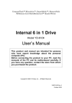
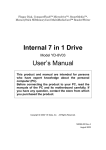
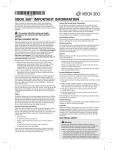
1
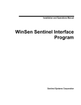
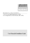
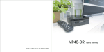
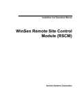
CompactFlash, Microdrive, SmartMedia, Memory Stick, Memory Stick PRO, SD Memory Card, MultiMediaCard, Reader/Writer (+ Floppy Disk Drive) Inter nal 7 in 1 Drive 3 Model YD-8V07 Inter nal 6 in 1 Drive 3 Model YD-8V09 User’s Manual This product and manual are intended for persons who have expert knowledge about personal computer (PC). Before connecting the product to your PC, read the manuals of your PC and its motherboard carefully. If you have any question, contact the store from which you purchased the product. www.yedata.com < PN 149511-02 Rev. B > Copyright © 2004 Y-E Data, Inc. All Rights Reserved. August 2004 Internal 7/6 in 1 Drive 3 User’s Manual 149511-02 Rev. B Important instructions for use This product usually comes built into a PC. If you install or remove the product from your PC by yourself, read the manual for the PC and pay much attention so as not to suffer an electric shock. Caution Before installing the Internal 7/6 in 1 Drive 3 into your PC, read through this manual. The driver software may have to be installed in advance. Before turning the power to your PC on or off, remove all media from the product. This product is a precision device. So do not drop the product, shake or strike it, or install it in locations exposed to heavy vibrations or high temperatures; doing so may cause the product breakdown. Do not disassemble or modify the product. Disassembly or modification may cause a breakdown, fire, or electric shock. Prohibition Do not use or store the product in wet locations. The moisture may result in a breakdown, fire, or electric shock. Do not insert anything other than specified memory cards. The insertion of a metal piece such as a coin or clip may lead to a breakdown, fire, or electric shock. Do not remove the media from the product when its access LED lamp is blinking. This product is intended for use in general electric equipment. Do not use it in equipment (aerospace equipment, atomic power control system, traffic-related equipment, transportation equipment, industrial robot, combustion equipment, various safety devices, life-support system, etc.) that require special quality and reliability, or that may threaten life or cause injury to the human body. z It is prohibited by copyright law to reproduce in whole or in part this software and User’s Manual or rent the software, without permission of the copyright holder. z We bear no liability for any pecuniary losses and lost profits resulting from use of the software included with this product, and any claims from third parties. z This software cannot be used on other than specified equipment. z The specifications of this software are subject to change without notice. z We assume no responsibility for any breakdown and damage caused by misuse, troubles from other equipment, undue repairs or modifications. z If this product should have any defect attributable to manufacture, we will exchange it with a new one, but cannot take on any more responsibility. Illustrative pictures in this manual may differ from the PC’s actual screens. Microsoft Windows is a registered trademark of Microsoft Corporation. CompactFlash is a registered trademark of SanDisk Corporation. SmartMedia is a registered trademark of Toshiba Corporation. MultiMediaCard is a trademark of Infineon Technologies AG and licensed MultiMediaCard Association.SD card Logo is a registered trademark. SONY, Memory Stick, Memory Stick PRO, MagicGate, and are registered trademarks of SONY Corporation. Y-E Data is a registered trademark of Y-E Data, Inc. Other company names and product names in this manual are trademarks or registered trademarks of their respective companies. Page 2 August 2004 Internal 7/6 in 1 Drive 3 User’s Manual 149511-02 Rev. B Contents 1. About this manual............................................................................................................. 4 2. Overview ............................................................................................................................ 4 3. Features of the Internal Drive 3....................................................................................... 5 3.1. Compatible OSes ......................................................................................................... 5 3.2. Compatible storage media ........................................................................................... 6 3.3. Internal 7 in 1 Drive 3................................................................................................... 7 3.3.1. Exterior features .................................................................................................... 7 3.3.2. Package Content................................................................................................... 7 3.4. Internal 6 in 1 Drive 3................................................................................................... 8 3.4.1. Exterior features .................................................................................................... 8 3.4.2. Package Content................................................................................................... 8 4. How to attach .................................................................................................................... 9 4.1. Handling notes ............................................................................................................. 9 4.2. How to mount the Internal Drive 3 ............................................................................... 9 4.3. How to connect the cables......................................................................................... 10 5. Before use ....................................................................................................................... 12 6. How to install the driver ................................................................................................. 13 6.1. How to install driver software ..................................................................................... 13 6.2. Icon and Corresponding Memory Card...................................................................... 13 7. How to operate the Internal Drive 3 .............................................................................. 14 7.1. How to operate the floppy disk drive.......................................................................... 14 7.2. Inserting a memory card ............................................................................................ 14 7.2.1. Inserting a CompactFlash card or Microdrive ..................................................... 14 7.2.2. Inserting a SmartMedia card ............................................................................... 15 7.2.3. Inserting a Memory Stick (Memory Stick PRO)................................................... 15 7.2.4. Inserting a MultiMediaCard or SD Memory Card................................................ 16 7.3. How to operate on Windows ...................................................................................... 17 8. Restrictions ..................................................................................................................... 19 9. Troubleshooting.............................................................................................................. 21 10. Product specification ................................................................................................... 23 10.1. Physical Specifications............................................................................................. 23 10.2. Electrical Specifications ........................................................................................... 23 10.3. Environment Specifications...................................................................................... 24 10.4. Cable Specifications................................................................................................. 24 10.5. Pin Assignment ........................................................................................................ 25 11. About inquiries.............................................................................................................. 26 Page 3 August 2004 Internal 7/6 in 1 Drive 3 User’s Manual 149511-02 Rev. B 1. About this manual This manual is intended for users who specialize in the assembly of build-to-order (BTO) PCs. If you are an end user, give great attention to the following items when using this product and manual. • Thoroughly read the manuals of your PC and its motherboard. • Before mounting the product in your PC, be sure to turn off the power to the PC and remove the PC’s power cord from the wall outlet. (Recent PCs remain internally live even after shutting down Windows.) • When connecting the USB cable supplied with this product to the motherboard, first read the manual for your motherboard to learn the position and pin configuration of the USB connector. If you don’t have your motherboard manual, please find a copy of it on the website of the company that manufactured the motherboard. Connecting the USB cable to a non-USB connector or to a wrong USB connector position may result in a serious breakdown of not only this product but also other equipment and the PC. Within this manual, each product is distinguished using the following term. Internal 7 in 1 Drive 3 is henceforth called "YD-8V07". Internal 6 in 1 Drive 3 is henceforth called “YD-8V09”. YD-8V07 and YD-8V09 are henceforth called “Internal Drive 3”. 2. Overview 1) The Internal Drive 3 is the built-in unit of Desktop PC. 2) The YD-8V09 contains USB (Universal Serial Bus)-compliant card reader/writers for CompactFlash, Microdrive, SmartMedia, Memory Stick, Memory Stick PRO, SD Memory Card, and MultiMediaCard cards. The card reader/writers are to be connected to the USB port of the PC. 3) The YD-8V07 is a combo product of a 3.5-inch floppy disk drive and USB compliant card reader/writers. The floppy disk drive is connected to the floppy disk controller built in your PC. The card reader/writers are connected to the USB port of the PC. 4) The Internal Drive 3 is compatible with the Hi-Speed USB. If Internal Drive 3 is connected to the personal computer’s Hi-Speed USB port, the Internal Drive 3 can accessed at a transmission speed of up to 480Mbps. If Internal Drive 3 is connected to the personal computer with Full-Speed USB port, it can access at the transmission speed of up to 12Mbps. 5) To use the Internal Drive 3, the following requirements must be met: the PC is equipped with a USB port; the OS installed on the PC supports USB; and the driver software the Internal Drive 3 is installed on the PC. Page 4 August 2004 Internal 7/6 in 1 Drive 3 User’s Manual 149511-02 Rev. B 3. Features of the Internal Drive 3 Internal 7 in 1 Drive 3 (YD-8V07) 1) The YD-8V07 contains a low-profile floppy disk drive. The YD-8V07 can be installed in the space occupied by a conventional 3.5-inch floppy disk drive. NOTE: Since the positions of an attachment screw may differ depending on PC, make reference to the manual of PC. 2) The YD-8V07 supports 3.5-inch floppy disks of 1.44MB or 720KB format. Internal 6 in 1 Drive 3 (YD-8V09) 1) The YD-8V09 can be installed in the space occupied by a conventional 3.5-inch floppy disk drive. NOTE: Since the positions of an attachment screw may differ depending on PC, make reference to the manual of PC. Common features of the YD-8V07 and the YD-8V09 1) The Internal Drive 3 can be used in many environments: Windows XP, Windows 2000, Windows Me, and Windows 98 Second Edition. 3.1. Compatible OSes PC Windows OS Windows XP Windows 2000 Windows Me Windows 98 Second Edition Driver software This product works with the standard driver in Windows. Install the driver from the CD-ROM to use this product with the special drive labels. Install the driver from the CD-ROM after installing Windows 2000 Service Pack 3 or greater. This product works with the standard driver in Windows. Install the driver from the CD-ROM to use this product with the special drive labels. Install the driver software from the CD-ROM. NOTE: Installation of the driver software before Windows2000 Service Pack 2 is possible. However, to use in the optimal environment, we recommend to install Windows 2000 SP 3 or greater. After Windows 2000 SP 3 or greater is installed, please install the driver software from the attached CD-ROM again. Page 5 August 2004 Internal 7/6 in 1 Drive 3 User’s Manual 149511-02 Rev. B 3.2. Compatible storage media Slot Floppy Disk Compatible media YD-8V07 CompactFlash Microdrive SmartMedia Memory Stick Memory Stick PRO SD Memory Card MultiMediaCard DOS-formatted Floppy Disk, 2HD 1.44MB and 2DD 720KB, are supported. DOS-formatted memory cards are supported. I/O cards such as modem, LAN, and PHS cards are not supported. DOS-formatted memory cards are supported. We have checked the operation of Type II Microdrives of up to 1 GB. When using a Microdrive, remove other memory cards. The Microdrive requires more power than other memory cards. If you use it with other memory cards at the same time, an error may occur due to a shortage of power. DOS-formatted memory cards between 4 MB and 128 MB are supported. Only 3.3 V cards (including those marked as 3 V) are supported. 5 V cards are not supported. You can use SmartMedia cards with an ID, but the ID feature is not supported. Music data and other protected file types with anti-piracy functions are not supported. ROM cards are not supported. DOS-formatted memory sticks between 4 MB and 128 MB are supported. MagicGate cards (white) are supported, but the MagicGate feature is not supported, so music data and other protected file types with anti-piracy functions are not supported. I/O cards such as GPS cards are not supported. DOS-formatted memory sticks between 256 MB and 1 GB are supported. MagicGate cards are supported, but the Magic Gate feature is not supported, so music data and other protected file types with antipiracy functions are not supported. DOS-formatted memory cards between 8 MB and 512 MB are supported. The Secure Digital feature is not supported, so music data and other protected file types with anti-piracy functions are not supported. SD I/O cards and SD Combo cards are not supported. DOS-formatted memory cards between 16 MB and 128 MB are supported. Keitaide-Music support cards are supported, but the Keitaide-Music feature (UDAC-MB protocol) is not supported, so music data and other protected file types with anti-piracy functions are not supported. The read/write speed of MultiMediaCard is much slower than other cards. It comes from the specifications of the cards. NOTE: 1) In this manual, the above seven types of media except floppy disk are generically called memory cards. 2) When using a Microdrive, do not use other memory cards at the same time because of the Microdrive’s large power consumption. 3) MultiMediaCards and SD Memory Cards use the same slot, so you cannot use them at the same time. 4) Memory Sticks and Memory Stick PROs use the same slot, so you cannot use them at the same time. Page 6 August 2004 Internal 7/6 in 1 Drive 3 User’s Manual 149511-02 Rev. B 3.3. Internal 7 in 1 Drive 3 3.3.1. Exterior features Connector for the FDD interface cable Power connector for the floppy disk drive Slot to insert a floppy disk Eject button for unloading the floppy disk USB cable for A Connector USB cable for 5-pin Connector Tapped holes used to mount Internal Drive 3 to PC Please use P TITE 3x5mm screws in package. Slot to insert a SD Memory Card Slot to insert a SmartMedia card FDD Access LED Slot to insert a CompactFlash card Slot to insert a Memory Stick card Memory Card Access LED [Important] For mounting on the PC, consult the manuals supplied with your PC and its motherboard. 3.3.2. Package Content Internal 7 in 1 Drive 3 USB 5-Pin-A Cable Driver CD-ROM P TITE 3 x 5mm screws X 4 pieces NOTE: Diskette or memory cards are not included and must be purchased separately. Page 7 August 2004 Internal 7/6 in 1 Drive 3 User’s Manual 149511-02 Rev. B 3.4. Internal 6 in 1 Drive 3 3.4.1. Exterior features Access LED USB cable for A Connector Tapped holes used to mount Internal Drive 3 to PC Please use P TITE 3x5mm screws in package. USB cable for 5-pin Connector Slot to insert a SD Memory Card Slot to insert a SmartMedia card Slot to insert a CompactFlash card Slot to insert a Memory Stick card [Important] For mounting on the PC, consult the manuals supplied with your PC and its motherboard. 3.4.2. Package Content Internal 6 in 1 Drive 3 USB 5-Pin-A Cable Driver CD-ROM P TITE 3 x 5mm screws X 4 pieces NOTE: Memory cards are not included and must be Purchased separately. Page 8 August 2004 Internal 7/6 in 1 Drive 3 User’s Manual 149511-02 Rev. B 4. How to attach 4.1. Handling notes Please keep the following in mind when handling the Internal Drive 3. • When handling the product, gently grasp the product along its sides near the attachment screw tap holes. Grabbing the product anywhere else may cause the unit to bend or deform, leading to breakdown and product failure. • Securely mount both sides of the drive to the PC or drive bay frame using the supplied screws. Attaching only one side may cause the drive to warp, leading to drive failure. • Please install the Internal Drive in a flat, horizontal position, with the CompactFlash card slot on the bottom. • Before working inside the computer, be sure to turn off the power to the PC and remove the PC’s Power cord from the wall outlet. (Recent PCs remain internally live even after shutting down Windows.) Wait 5 seconds after removing the power cord from the wall outlet to prevent electrical shock and damage. • Take all action against static electricity, before working inside the computer. 4.2. How to mount the Internal Drive 3 1) Refer to the manual of your PC and the manual of the motherboard, it should explain how to prepare a drive bay for installation of a new drive like the Internal Drive 3. NOTE: When there is no 3.5-inch bay, use a commercial 5-inch bay adapter. 2) Insert the Internal Drive 3 into the drive bay of your PC. 3) Align the screw holes on the sides of the Internal Drive 3 with the PC-side mounting holes. 4) Secure the Internal Drive 3 with four P TITE 3 x 5mm long screws. (If you use screws longer than 5 mm, they may interfere with the inner parts of this product, and it may cause a problem. Please use the screws included in this package.) • Tightening torque: 29.4cN/m, (3kgf/cm) • Recommended screw length: P TITE 3 x 5mm long screws (It is assumed that the PC-side bracket is 0.5 to 1 mm thick.) (Screw-in depth on the Internal Drive 3 side: MAX. 5mm) Page 9 August 2004 Internal 7/6 in 1 Drive 3 User’s Manual 149511-02 Rev. B 4.3. How to connect the cables 1) Plug the 5-pin connector of the USB cable (the interface’s internal cable) into the USB terminal on the motherboard. Check your motherboard user manual for the location of the USB terminal. If it is difficult to connect the motherboard with the 5-pin connector, disconnect the 5-pin - A cable, and connect the USB A connector directly to a standard extemal USB port on your computer. NOTE: Pay attention to the direction of the connector. See the reference illustration below. In case of using a 5-pin connector No.3 Green (+DATA) No.4 Black (Ground, Shield) No.2 White (-DATA) No.1 Red (VCC) 5-pin connector Internal USB terminal NOTE: For the pin configuration, refer to the motherboard user’s manual. When pin configuration differs, unplug the individual wires and reinsert them according to the pin configuration of the motherboard. In case of using a USB A connector 5-pin - A cable USB A connector 5-pin connector Page 10 August 2004 Internal 7/6 in 1 Drive 3 User’s Manual 149511-02 Rev. B 2) If you are using a YD-8V07, you also need to connect the FDD power cable. Plug the FDD power connector of the PC into the YD-8V07 power connector. NOTE: Pay attention to the direction of installation. Improper connection may causes damage or fire. 3) If you are using a YD-8V07, you also need to connect the FDD interface cable. Align pin no.1 of the PC FDD 34-pin connector with that of the YD-8V07 FDD I/F connector. Then plug the FDD 34-pin connector of the PC into the YD-8V07 FDD I/F connector. NOTE: Pay attention to the direction of installation. If improper connection is made, the product will not operate correctly. FDD power connector Connector and cable diagram FDD I/F connector Internal 7 in 1 Drive 3 (YD-8V07) PIN No.1 USB cable USB A connector 5-pin connector Internal 6 in 1 Drive 3 (YD-8V09) USB mini B connector USB cable USB A connector 5-pin connector Page 11 August 2004 Internal 7/6 in 1 Drive 3 User’s Manual 149511-02 Rev. B 5. Before use If the Internal Drive 3 has been mounted in the PC before the installation of OS; On Windows 98SE, the memory card drive is recognized as other device and does not work, but the installation of the driver software solves the problem. On Windows XP, 2000 and Me, removable disk icons are displayed. • When mounting the Internal Drive 3 to the PC that already has the installed OS, install driver software for the internal Drive 3 before the mounting it. • If the Internal Drive 3 hardware is mounted before the installation of the driver software for the Internal Drive 3, and the hardware wizard appears, be sure to “cancel” the wizard, and then start up the installer. • The floppy disk drive works with the OS-standard driver, so it is unnecessary to install driver software for the FDD. [Important] If an earlier version of the driver software for our USB Memory Card Reader/Writer is installed, uninstall it before installing the Internal Drive 3 driver. To uninstall the driver software, refer to “USB Card Reader Installer Users Guide.” Page 12 August 2004 Internal 7/6 in 1 Drive 3 User’s Manual 149511-02 Rev. B 6. How to install the driver 6.1. How to install driver software The driver CD-ROM contains software for Windows XP, 2000, Me and 98SE. Insert the driver CD-ROM into the PC. The installer will automatically start up. The Installer recognizes the OS version, and installs the appropriate software. See "USB Card Reader Installer Users Guide" about the method of installation. 6.2. Icon and Corresponding Memory Card 1) Windows automatically recognizes Internal Drive 3, and will perform the addition of new hardware. After installation, open “My Computer”; you should see four new icons as shown in the following table. The assigned drive letters (E: F: etc.) depend on your PC. Note: If you install the driver software after attaching Internal Drive 3 to the PC, a generic removable disk icon may be displayed. In this case, push the F5 key, or shutdown and restart the PC. Then the icons will be displayed correctly. 2) If one icon is selected and double-clicked, the files on the memory card will be displayed and can be accessed. Icon SP1 Windows XP Without SP Windows 2000, Me, 98SE Corresponding Memory Card CompactFlash Microdrive SmartMedia Memory Stick Memory Stick PRO SD Memory Card MultiMediaCard Page 13 August 2004 Internal 7/6 in 1 Drive 3 User’s Manual 149511-02 Rev. B 7. How to operate the Internal Drive 3 7.1. How to operate the floppy disk drive The YD-8V07’s floppy disk drive is a standard 3.5-inch floppy disk drive, so it can be operated in the same manner as a standard floppy disk drive. 1) Inserting a floppy disk The floppy disk should be inserted into the floppy disk slot located in the upper part of the YD-8V07. When inserting the floppy disk, push it in as far as it will go. When the floppy disk is inserted correctly, Eject button for unloading pops out. Floppy disk Eject button When a floppy disk is inserted, the button pops out. Floppy disk 7.2. Inserting a memory card 7.2.1. Inserting a CompactFlash card or Microdrive The CompactFlash card and Microdrive operate as an USB-interface removable disk. The CompactFlash card or Mcirodrive should be inserted into the CompactFlash card slot located in the lower left-hand part of the Internal Drive 3. When inserting the card, push it in as far as it will go. When the card is inserted correctly, it protrudes about 8 mm. The card slot is designed as to avoid from insertion of wrong direction. YD-8V07 ∆ sign YD-8V09 CompactFlash or Microdrive Important: If you insert the card upside down or sidways, the drive may be damaged. Turn up the surface with ∆ sign which shows the insertion direction. Page 14 August 2004 Internal 7/6 in 1 Drive 3 User’s Manual 149511-02 Rev. B 7.2.2. Inserting a SmartMedia card The SmartMedia card operates as a USB-interface removable disk. The SmartMedia card should be inserted into the SmartMedia card slot located in the upper left -hand part of the Internal Drive 3. When inserting the card, push it in with the golden contact side down as far as it will go. When the card is inserted correctly, it protrudes about 5 mm. The card slot is designed as to avoid from insertion of wrong direction. Golden contact YD-8V07 Notch YD-8V09 SmartMedia [Important] Insert with the golden contact down. 7.2.3. Inserting a Memory Stick (Memory Stick PRO) The Memory Stick operates as a USB-interface removable disk The Memory Stick (Memory Stick PRO) should be inserted into the Memory Stick slot located in the lower right-hand part of the Internal Drive 3. When inserting the card, push it in as far as it will go. The card slot is designed as to avoid from insertion of wrong direction. YD-8V07 YD-8V09 Memory Stick Page 15 August 2004 Internal 7/6 in 1 Drive 3 User’s Manual 149511-02 Rev. B 7.2.4. Inserting a MultiMediaCard or SD Memory Card The MultiMediaCard and SD Memory Card operate as a USB-interface removable disk. The MultiMediaCard or SD Memory Card should be inserted into the SD Memory Card slot located in the upper right-hand part of the Internal Drive 3. When inserting the card, push it in as far as it will go. The card slot is designed as to avoid from insertion of wrong direction. YD-8V07 YD-8V09 MultiMediaCard or SD Memory Card Page 16 August 2004 Internal 7/6 in 1 Drive 3 User’s Manual 149511-02 Rev. B 7.3. How to operate on Windows 1) Accessing to the Media (Floppy Disk, Memory Card, …, etc) FDD Access LED turns on during the access. Memory Card Access LED blinks during the access. YD-8V07 FDD Access LED Memory Card Access LED YD-8V09 Access LED 2) Removing the Media (Floppy Disk, Memory Card, …, etc) • Removing a floppy disk (YD-8V07) To remove the floppy disk, make sure the access LED is turned off, then press the Eject button to remove. Eject button FDD Access LED Page 17 August 2004 Internal 7/6 in 1 Drive 3 User’s Manual • 149511-02 Rev. B Removing a memory card Make sure that a file on the media is not being used by an application or being copied, before removing the media. If you remove the media during access, the blue screen may be shown or the data on the media may be destroyed. To avoid accident, remove cards as follows. 1) In my computer, right click the appropriate drive icon. 2) Left click [Eject] on the context menu that appears. 3) Wait until LED stops blink. It is recommended to wait 30 seconds or more for delayed write. 4) Pull out the memory card with your fingers. 4) Pull out memory card YD-8V09 1) Right click 2) Left click 3) Wait for access LED to turn off Important: On Windows XP and 2000, the card may be accessed by a delayed write operation after the access LED stops blink. For safety purposes, wait 30 seconds or more after the access LED stops the blink, then remove the media. Page 18 August 2004 Internal 7/6 in 1 Drive 3 User’s Manual 149511-02 Rev. B 8. Restrictions 1) Precautions for use on Windows XP, 2000, and Me Windows XP, 2000 and Me show the removal icon on the task tray, but you should not use this icon. If you disconnect the Internal Drive 3, the Internal Drive 3 cannot be used any more until Windows XP, 2000 and Me is restarted. 2) Formatting of Media To format a floppy disk, right click on the appropriate drive icon in My Computer, and select [Format] in the displayed menu. Do not format (initialize) memory cards on Windows. If you format a memory card on Windows, it may not be useable for devices such as digital cameras due to the difference of the format type (FAT size, cluster size, hard disk type or super floppy disk type). If you have a digital camera, format memory cards with your camera. 3) Standby The Internal Drive 3 supports the standby function based on the PC-2000 standard, not all PCs’ standby function. If the standby operation of your PC causes any problem, do not use the function. During standby, do not insert or remove any media. 4) Supported SmartMedia card The Internal Drive 3 supports 3.3-volt and 3-volt SmartMedia cards, not the old 5-volt type. 3.3V and 3V type 5V type Important: The Internal Drive 3 is designed so that the 5-volt SmartMedia card cannot be inserted. Do not insert it by force. Page 19 August 2004 Internal 7/6 in 1 Drive 3 User’s Manual 149511-02 Rev. B 5) SmartMedia card handling If the contact area of a SmartMedia card is dirty, a read error may occur. Keep the contact area clean. Do not touch the gold contact area. Do not twist or warp the card. Protect the card from static electricity. 6) SmartMedia card with ID The Internal Drive 3 does not support the ID information of the SmartMedia card, but allows you to use any SmartMedia card with an ID as a usual media. 7) Restrictions on DOS mode When in DOS mode, the only the floppy disk drive can operate. The card reader/writers do not operate in DOS mode. To use those reader/writers, start up Windows. 8) Antivirus software When memory-resident antivirus software runs on your PC, the PC may become unusually slow or hang up. In this case, uncheck the media of the Internal Drive 3 in the anti-virus software. 9) Floppy disk drive interface cable YD-8V07 The YD-8V07 floppy disk drive interface should be connected to the floppy disk controller on the PC’s motherboard using a 34-pin ribbon cable. The 34-pin ribbon cable usually has two connectors for floppy disk drives. Connect the YD-8V07 floppy disk drive to the connector of the end side for Drive A:. If you have a second floppy drive, connect it to the middle connector for Drive B:. Computer side Drive B: Drive A: Important: Be careful that Pin 1 of the cable is connected to Pin 1 of the interface. Usually, there are marks, such as a red line or ∆ sign, indicating the Pin 1 side of the 34-pin ribbon cable. NOTE: A 34-pin cable is not supplied with this product. 10) BIOS settings for the floppy disk drive YD-8V07 When setting the PC’s BIOS, set the floppy disk drive to legacy 3.5-inch 1.44-MB. Some PCs provide 3-mode support in their BIOS. However, the YD-8V07 does not support the 3-mode. Setting of 3-mode support may disable normal access to the drive under Windows. Page 20 August 2004 Internal 7/6 in 1 Drive 3 User’s Manual 149511-02 Rev. B 9. Troubleshooting 1. PC does not startup after the connection. If your PC does not startup after the connection of the Internal Drive 3, the BIOS may incompatible with the Internal Drive 3. Try following steps be 1-1. Check web site of the PC or motherboard maker. If update programs of the BIOS are available, use it first. 1-2. If latest BIOS doesn’t solve the problem, find "Legacy USB Support" item in the BIOS setting and, if it is available, disable it. 1-3. If the motherboard has other USB port, try to use the other one, because it is known issue that reproduced on some motherboards of AOpen. 1-4. Remove all memory cards from the slot of the Internal Drive 3. Some motherboards hang up if a CF card is in the card reader at the startup. 1-5. Change the boot priority of the FDD lower than HDD. 1-6. Change the boot priority of the HDD to top, if step 1-5 could not solve the trouble. 1-7. If the above have had no effect, the remaining solution is replacing the USB cable with one which have ordinary USB A plug, and put the plug into the connector of your PC on demand after the startup. 2. Drive icons of the card reader are not displayed. Check followings. 2-1. Make sure the USB cable is connected properly. Note: The assignment of the pins needs to correspond with the motherboard. 2-2. If your are using Windows 2000 SP3 or later, check the "Device Manager" information. (1) Check "USB Mass Storage Device" in the "Universal Serial Bus controller". If there is no warning, it should be working properly. (2) If steps in (1) can’t be followed, try the connection of the YD-8V07 to the other USB connector, if available. (3) If drive icons do not appear even though the steps in (1) are followed, the assignment of the logical drive may be conflicted or the logical drive may be disabled. To check it, run "Computer Management" program as following steps. (3-1) Open "Control Panel". (3-2) Open "Administrative Tools". If you can't find "Administrative Tools", click "Performance and Maintenance" at first. (3-3) Start "Computer Management". (3-4) Select "Storage" - "Disk Management". (3-5) You can find removable drives in the bottom right window. If your problem is the assignment of the drive letter, you can change it here. (4) The drive icon may also be hidden if any network drives are assigned as the same letters of the card reader's. Check the drive letters, if you use network drives. (5) Proceed to next step 3 if above steps do not solve your problem. Page 21 August 2004 Internal 7/6 in 1 Drive 3 User’s Manual 149511-02 Rev. B 3. Custom Icons for the YD-8V07 are not displayed. Check following items. 3-1. If you have installed custom icon driver for the card reader of other brand, uninstall it if possible. Or, if the upgraded one is available, try the upgrade. 3-2.Try following sequence to refresh the driver software if you have installed other removable storage devices or you have used network drives. (1) On the device manager program, double click 'Universal Serial Bus controller' item to view the individual items. Next, double click 'USB Mass Storage Device' item to open the property window, then disable the item using popup menu placed on the bottom side of the window. (2) Restart your PC. (3) Enable the USB Mass Storage device again, on the device manager in order to reinstall the device driver. 4. Floppy Disk Drive (FDD) does not work. Check following items. 4-1. First of all, make sure the drive icon of the floppy is displayed in the My Computer window normally. If the icon is not found, make sure that the floppy related BIOS settings; e.g. the type of the drive is set to 3.5" 1.44M, the Floppy Disk controller is enabled, and so on. Regarding the setting of the BIOS, refer to the manual of your PC, because the setting items are depend on the PC. 4-2. If the LED of the FDD is constantly on, the 34 pins interface cable has probably been connected upside down. Check the connecting direction. Note: That inserted floppy diskettes may be damaged during the above condition, even if the write-protection of the diskettes are enabled. In the worst case, the motherboard may also be damaged. 4-3. If accessing the drive does not turn the LED of the FDD on, the power cable or the interface cable may not be connected properly. Make sure the connection. Note: that wrong connection may break motherboard. 4-4. If the problem continues, it is good idea to connect another standard 3.5" 1.44M FDD to confirm that the computer is working order and to determine that it is the YD-8V07, and not the computer, is not functioning properly. Page 22 August 2004 Internal 7/6 in 1 Drive 3 User’s Manual 149511-02 Rev. B 10. Product specification 10.1. Physical Specifications Description Specification Size (Excluding protrusion) 101.6±0.5 mm (W) X 25.4±0.5 mm (H) X 154.5±1 mm (D) Weight YD-8V07: 285 g (TYP) YD-8V09: 115 g (TYP) Color (Standard) Black Drive Unit Ivory 10.2. Electrical Specifications Description Specification FDD (only YD-8V07) USB Card Reader USB spec. REV. 2.0 Full Speed (12Mbps) Hi-Speed (480Mbps) USB Specification 34 Pin Standard Power Supply Voltage DC 4.75V to 5.25V DC 4.75 V to 5.25 V Current Consumption 830 mA (Max) *1 500 mA (Max) *2 Regulations UL, cUL, CE, FCC-Class B, VCCI Class B*3 Access LED Green color: lights on during access. Yellow color: Usually lights on and blinks during access. *1 Test Condition: Power Supply Voltage is DC 5.0 V, and the floppy disk is general one. *2 Except a case of using a Microdrive. *3 For use with Limited power source. Page 23 August 2004 Internal 7/6 in 1 Drive 3 User’s Manual 149511-02 Rev. B 10.3. Environment Specifications Description In operating In non-operating Temperature 5 - 40 °C -20 - 60 °C Relative Humidity 30 - 80 %RH No condensation Maximum Wet Bulb Temperature 29°C -------- Vibration Sweep Time: 5.6 minutes Test time: 10 minutes (each direction) Direction of Sweep: XYY’ Shock Direction of Shock: XYY’ 9.8 m/s2 (10 - 200 Hz) (1.0G) 4.9 m/s2 (200 - 500 Hz) (0.5G) 49 m/s2 (11 ms Half Sine) (5.0 G) 19.6 m/s2 (10 to 500 Hz) (2.0G) 980 m/s2 (11ms Half Sine) (100G) 10.4. Cable Specifications Specification Description USB Cable (Connected) USB Cable (Attached) Connector Cable length Color Type mini B to Type A 70 cm Black Type A receptacle to 5pin connector Housing : RE-05 (JST) or Equivalent Terminal : RF-SC2210 (JST) or Equivalent 10 cm Black Page 24 August 2004 Internal 7/6 in 1 Drive 3 User’s Manual 149511-02 Rev. B 10.5. Pin Assignment USB Cable (Connected) Lead Wire USB type mini B Connector Pin No. Signal name Color USB type A Connector Pin No. 1 VCC Red 1 2 -DATA White 2 3 +DATA Green 3 4 (Non Connection) 5 Ground Black 4 Plug Shell Shield Black Plug Shell USB Cable (Attached) Lead Wire USB Type A receptacle Connector Pin No. Signal name Color 1 VCC Red 1 2 -DATA White 2 3 +DATA Green 3 4 Ground Black 4 Plug Shell Shield (Non Connection) 5 Pin Connector 5 No.3 Green (+DATA) No.4 Black (Ground, Shield) No.2 White (-DATA) No.1 Red (VCC) 5-pin connector Important: Before connecting, make sure the pin configuration corresponds with that on the PC; consult the manual for your PC. Page 25 August 2004 Internal 7/6 in 1 Drive 3 User’s Manual 149511-02 Rev. B 11. About inquiries Inquiries should be directed to the store from which you purchased the product or any store that is listed on the package. The latest information and the most up-to-date version of the driver software can be found on the following web site. Product information available at: http://www.yedata.com/products/cardreaders/index.shtml Download driver software from: http://www.yedata.com/support Page 26 August 2004