1
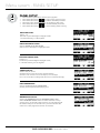
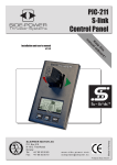
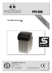
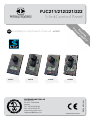
SIDE-POWER Thruster Systems Installation and user’s manual v 2.0.9 is rd th a p bo ee n K al o u an m EN PJC211/212/221/222 S-linkControl Panel ! PJC212 PJC221 PJC222 SLEIPNER MOTOR AS P.O. Box 519 N-1612 Fredrikstad Norway Tel:+47 69 30 00 60 Fax:+47 69 30 00 70 www.side-power.com [email protected] Made in Norway PJC211 © Sleipner Motor AS 2015 Contents Product Features...............................................................................................................................................................................................3 Panel layout & functions .............................................................................................................................................................................. 4-5 Display in normal use ......................................................................................................................................................................................6 symbols explanations................................................................................................................................................................................... 7-8 Alarm DC system..............................................................................................................................................................................................9 Alarms ( AC and hydraulic thrusters ).......................................................................................................................................................... 10 Menu system.................................................................................................................................................................................................. 11 Menu system - Language - Stabilizer - default settings............................................................................................................................ 12 Setup procedure............................................................................................................................................................................................ 13 Menu system - Setup................................................................................................................................................................................14-19 System devices....................................................................................................................................................................................... 14 1. PHC 024................................................................................................................................................................................... 14 2. PDC 201................................................................................................................................................................................... 17 3. PDC 101................................................................................................................................................................................... 17 4. MAIN SWITCH......................................................................................................................................................................... 18 5. PPC800, SR150 000, SR61242..........................................................................................................................................18-19 6. RCRS-1...................................................................................................................................................................................... 20 7. MSI8730................................................................................................................................................................................... 20 Hold calibration...................................................................................................................................................................................... 21 Menu system - Info........................................................................................................................................................................................ 22 Menu system - Panel Setup........................................................................................................................................................................... 23 Alarm descriptions ...................................................................................................................................................................................24-25 Technical specifications................................................................................................................................................................................ 26 S-link system example................................................................................................................................................................................... 27 Measurements................................................................................................................................................................................................ 28 Connections................................................................................................................................................................................................... 29 Notes..........................................................................................................................................................................................................30-31 DO NOT connect any other control equipment to the S-link controlled products except Side-Power original S-link products or via a Side-Power supplied interface product made for interfacing with other controls. Any attempt to directly control or at all connect into the S-link control system without the designated and approved interface, will render all warranties and responsibilities for the complete line of Side-Power products connected void and null. If you are interfacing by agreement with Sleipner and through a designated and approved interface, you are still required to also install an original Sidepower control panel to enable efficient troubleshooting if necessary DECLARATION OF CONFORMITY We, Sleipner Motor AS P.O. Box 519 N-1612 Fredrikstad, Norway declare that this product with accompanying standard remote control systems complies with the essential health and safety requirements according to the Directive 89/336/EEC of 23 May 1989 amended by 92/31/EEC and 93/68/EEC. 2 PJC211/212/221/222 version 2.0.9 - 2015 Product Features Control panel with S-link™ CAN-bus connection Product features • For proportional thruster control with DC, AC and Hydraulic Thrusters (Hydraulic thrusters PJC-221/222 only). • Finger tip control speed control with purpose designed joysticks • Hold - function for easy docking, runs thrusters at selected power (Dual joysticks PJC-212/222 only) • Back-lit LCD display with instant feedback - System status / alarms - Amount of thrust & direction of thrust • Interactive multi-language menus • CAN-Bus communication with thrusters and accessories • Plug & play cables with compact connectors • Diagnostics and system setup via panel • Built-in audible alarm “buzzer” • Connector for external “buzzer”/loud audible alarms • Supports Side-Power retractable thrusters with or without Speed Control PJC211 PJC212 PJC211/212/221/222 PJC221 version 2.0.9 - 2015 PJC222 3 Panel layout & functions PJC-211 Speed control joystick for thruster Information display, see following pages for details. Press both “ON” buttons simultanously to activate control panel. MENU Press to de-activate control panel or cancel or go back in menu system or mute internal alarm buzzer. MENU Press to change between day and night light Press and hold for 3 seconds to access menu system and choose items in menus PJC-212 Holding function for continous running of bow and stern thrusters together in the direction of the arrows at selected power Press “+” for more and “-” for less power (6 steps). Speed control joystick for bow thruster. Speed control joystick for stern thruster. If any control unit are running the thruster in opposite direction to the hold function, the hold function will be deactivated. Information display, see following pages for details. Press both “ON” buttons simultaneously to activate control panel. Press to de-activate control panel or cancel or go back in menu system or mute internal alarm buzzer. MENU Press to change between day and night light. 4 Press and hold for 3 seconds to access menu system and choose items in menus. PJC211/212/221/222 version 2.0.9 - 2015 Panel layout & functions front s_v strek_PJC222.pdf 1 04.11.2010 11:05:34 PJC-221 Speed control joystick for thruster Information display, see following pages for details. Press and hold “ON” button for 1 second to activate control panel. MENU Press to de-activate control panel or cancel or go back in menu system or mute internal alarm buzzer. STOP Press to change between day and night light. Press and hold for 3 seconds to enter menu system PJC-222 Emergency stop button front s_v strek_PJC222.pdf 1 04.11.2010 11:05:34 Holding function for auto-running of bow and stern thrusters together in the direction of the arrows at selected power Speed control joystick for bow thruster Press “+” for more and “-” for less power (6 steps). Speed control joystick for stern thruster If any control unit are running the thruster in opposite direction to the hold function, the hold function will be deactivated. Information display, see following pages for details. Press and hold “ON” button for 3 seconds to activate control panel. Press to de-activate control panel or cancel or go back in menu system STOP Press to change between day and night light. Press and hold for 3 seconds to enter menu system Emergency stop button PJC211/212/221/222 version 2.0.9 - 2015 5 Display in normal use Status indicators for bow thruster. (Port bow thruster in a dual bow thruster setup). BOW BOW-STB Battery indicator will be shown here in a single DC electric bow thruster setup. Runtime indicator will be shown here in a single DC electric bow thruster setup. Status indicators for stern thruster. (Port bow thruster in a dual stern thruster setup) Runtime indicator will be shown here in a single DC electric stern thruster setup. Status indicators for starboard bow thruster. Only shown in a dual bow thruster setup. STERN STERN-STB Status indicators for starboard stern thruster. Only shown in a dual stern thruster setup. Battery indicator will be shown here in a single DC electric stern thruster setup. Examples of display view for different panels applications: PJC211/221: DC Electric Bow thruster PJC221: Hydraulic Bow thruster PJC221: AC Electric Bow thruster PJC212/222: DC Electric Bow thruster DC Electric Stern Thruster PJC222: Hydraulic Bow thruster Hydraulic Stern Thruster PJC222: AC Electric Bow thruster Hydraulic Stern Thruster PJC211/221: DC Electric Stern thruster PJC212: Dual DC Electric Bow thrusters Dual DC Electric Stern thrusters PJC222: Dual Hydraulic Bow thrusters Dual Hydraulic Stern thrusters PJC222: Dual AC Electric Bow thrusters Dual AC Electric Bow thrusters PJC221: Dual AC Electric Bow thrusters PJC221: Dual Hydraulic Bow thrusters 6 PJC211/212/221/222 version 2.0.9 - 2015 Symbols explanations DC Thrusters: Battery indicator. From 8.5V to 12V for 12V thrusters, 15V to 24V for 24V thrusters Motor temperature indicator. From 70°C/ 158°F to 130°C/266°F. Symbol shown when a DC Thruster is used in a dual bow or dual stern setup: Battery indicator. From 8.5V to 12V for 12V thrusters, 15V to 24V for 24V thrusters Motor temperature indicator. From 70°C/ 158°F to 130°C/266°F. AC Thrusters: Motor temperature indicator. Hydraulic Thrusters: Hydraulic oil temperature indicator. Retractable Thrusters: Symbol shown when the thruster deploys. Symbol shown when the thruster retracts. Symbol shown when the thruster is in position OUT. When the thruster is deployed and no input is given via the joysticks/buttons over a 10 second period, the panel will give an audible signal every 10th second to tell that the truster is still deployed. PJC211/212/221/222 version 2.0.9 - 2015 7 Symbols explanations Thrust power and direction, Bow thruster(s) Input from bow joystick on this panel. The thrust indicator will be shown in this position on a single joystick panel if the thruster is defined as a bow thruster Thrust power and direction, Stern thruster(s) Input from stern joystick on this panel The thrust indicator will be shown in this position on a single joystick panel if the thruster is defined as a stern thruster. Indicating amount of thrust set by other control units in the system, i.e additonal PJC panels, 8700 Retract panel, input via 8730 S-link external switch interface, S-link remote control etc. If two or more units are set to run the thruster in opposite direction, this information will not be shown. FIRST TIME SETUP After installation of an S-link thrusters system, a System Setup procedure to setup control panels, thrusters and additional equipment must be completed (ref. procedure on page 13) before the system can be used. Write down all the S- Link devices and serial number one page 27. 8 PJC211/212/221/222 version 2.0.9 - 2015 Alarms DC System front s_v strek_PJC222.pdf 1 04.11.2010 11:05:34 When there is a problem or a fault, the panel will show this alarm situation by changing LCD display backlight to red color. The panel will also change to show “Alarm Info” on the bottom of the screen, indicating that by pressing the corresponding button below, you will get information about what the problem is (examples below). Example PJC 212: Alarm code Name and location of device No. of alarms Alarm description Scroll bar MENU Example PJC 222: STOP (Button below this symbol pressed) Use joystick to scroll if more than two alarms Reset alarm and Return Refer to Alarm code overview/table on pages 18-19 for full description on the different alarm codes. Non auto reset alarms Some alarms do not reset, and needs confirmation from user to be reset. This alarms need reset: Alarm code Description Alarm code Description 1 Motor Overcurrent 14 Supply Voltage Fault 2 Controller Overtemp 15 Fuse Blown 5 Low Voltage 17 Motion OUT Fault 7 IPC Error 18 Motion IN Fault 8 Critical Error 19 Actuator Fault 9 Low Motor Current 20 Pos.Sensor Fault 10 Motor Contactor 23 Low Oil Level 11 System Error 29 AC Motor Sensor Fault 12 No Communication 34 VFD Fault 13 Motor Temp Sensor 35 Warning Low Voltage When using the “HOLD” function The internal and external (if fitted) buzzer will give the following warning signals: Warning signals Cause 1. Single short beep every 2.4 sec. • • Voltage below 9.3V/17.5V (12V/24V system). o o o o Temperature above 85 C/185 F (80 C/176 F for PPC800 FW V1.013 or older/ SR150000 FW V1.006 or older). None 2. Two short beeps every 2.4 sec. • • Voltage below 8.9V/16.3V (12V/24V system). o o o o Temperature above 100 C/212 F (90 C/194 F for PPC800 FW V1.013 or older/ SR150000 FW V1.006 or older). None 3. Red backlight in display and continous short beeps. • • Voltage below 8.5V/15V (12V/24V system). o o o o Temperature above 115 C/239 F (100 C/212 F for PPC800 FW V1.013 or older/ SR150000 FW V1.006 or older). None 4. Red backlight in display and continous short beeps. If one or more of the thrusters enters an alarm state - Voltage below 8 Volts (both 12 and 24 Volt systems) or temperature o o o o above 130 C/266 F (110 C/230 F for PPC800 FW V1.013 or older/ SR150000 FW V1.006 or older): PJC211/212/221/222 Effect version 2.0.9 - 2015 “HOLD” function are cancelled. Both thrusters will stop. Temperature must o o o o drop below 115 C/239 (100 C/212 for PPC800 FW V1.013 or older) before the thruster can be operated again. 9 Alarms (AC & hydraulic thrusters) When there is a problem or a fault, the panel will show this alarm situation by the LCD display in red color. All alarms will show in display when panel is turned OFF. This requires the S-link and other system devices have power. Critical alarms will activate internal and external buzzer (a long beep every 2 seconds). The buzzer can be silenced by pushing the button below , this will also silence all other panels in the system CRITICAL ALARMS: Alarm code For safety! When oil pressure goes below 10bar, the HOLD function is deactivated. Description Emergency stop 22 High oil temperature 23 Low oil level 26 High speed stabilizer not active 27 Stabilizer fault 28 Hydraulic AC motor power pack overtemp 29 AC thruster sensor fail AC 31 AC thruster overtemp SPECIFIC ALARMS STOP BUTTON Pressing the STOP button on a hydraulic panel will activate the dump valve and all hydraulic consumers will be disabled. NB: FOR EMERGENCY USE ONLY Panel will not run thrusters. will mute buzzer Pressing button below alarm at all panels and show the alarm info screen. ALARM SHOWN ON INACTIVE PANELS! This screen will be shown on inactive panels if any of the following critical alarms occur: • • • • • Low oil level High oil temperature Hydraulic AC motor power pack overtemp AC thruster overtemp AC thruster fail will mute buzzer Pressing button below alarm at all panels and show the alarm info screen. WARNING! HIGH SPEED. STABILIZER NOT ACTIVE! (Only for yachts equipped with a Side-Power Stabilizer system) Warning will show when yacht is driven at high speed with stabilizer system inactive. Please refer to the Stabilizer ECU manual for speed settings. will mute buzzer Pressing button below alarm at all panels and show the alarm info screen. 10 PJC211/212/221/222 version 2.0.9 - 2015 Menu system front s_v strek_PJC222.pdf 1 04.11.2010 11:05:34 Access menu system by pressing and holding Menu button for 3 seconds. Move around in menus by using joysticks. Follow instructions on the screen and press the buttons below the symbols indicated on LCD screen. STOP MENU PJC 212 PJC 222 MAIN MENU ITEMS: Move between main menu items with the (stern) joystick. Language Stabilizer ( If installed) Setup Info Default settings Panel setup BUTTON SYMBOLS On the bottom line of the display, a symbol will be shown over the buttons below. These symbols will show what function each corresponding button has in the selected menu entry. Return to previous menu. Select highlighted menu text / Save edited parameter. Edit highlighted parameter. PJC211/212/221/222 Cancel editing without saving. version 2.0.9 - 2015 This symbol indicates that the (stern) joystick is used to move between menu items / parameters. 11 Menu system LANGUAGE • LANGUAGE • Choose language by moving joystick: English, Norwegian, German, French, Spanish, Italian and Danish. Press the button below to set the language to the highlighted menu entry. A star (*) on each side indicates the laguage set. STABILIZER (Shown only for yachts equipped with a Side-Power Stabilizer system) STABILIZER (Default in systems with stabilizers) to edit the selected parameter. Press the button below ON/OFF will start to blink, use joystick to alter value. Press the button below to save edited parameter to device. 1. Stabilizer: Values: ON/OFF Switches the stabilizer ON or OFF. • • 2. AnySpeed: • Values: ON/OFF • Switches the zero speed/at anchor stabilization ON or OFF. DEFAULT SETTINGS DEFAULT • Reset all settings to factory default - follow instructions on screen • • Press the button below to confirm reset The following parameters/values will be set to the factory settings: Language = English Backlight Level = 5 Backlight Night Color = Green Backlight Nightlevel =1 Timer Auto-Off = 05 min Hold Calibration =70% Bow and Stern All system devices will be erased from memory. (Setup procedure must be followed to reconfigure the system) 12 PJC211/212/221/222 version 2.0.9 - 2015 Setup procedure The setup procedure requires knowledge of the serial numer and location of all the S-link devices. Write this down in the form on the last page to have the information at hand when doing a manual setup. At the first startup of a new system, one of the two screens below will be shown: 1. SETUP DO NOT MATCH SYSTEM. FOR AUTO SETUP New devices found. Not in conflict with other devices. Press button below the -symbol to auto setup. Thrusters can not be operated to auto setup is completed. 2. RUN SETUP! DEVICES IN CONFLICT! Detected devices in conflict. Two or more thrusters defined as same instance (bow/stern/bow STB/Stern STB). Run Setup procedure to correct. Thrusters cannot be operated until seup is completed. 2.1 Press and hold the button marked “MENU” for 3 seconds to enter the menu system. Use the (stern) joystick to select “SETUP”, Press button below the -symbol to enter the”SETUP”-menu. 2.2 Use the (stern) joystick to select “SYSTEM DEVICES”, Press button below the -symbol to enter the”SYSTEM DEVICES”-menu. 2.3 Use the (stern) joystick to set the pin code one number at the time, press button below the -symbol to jump to next number and confirm. The pin code is “9 9 9 9”. NOTE: Re-entering the SYSTEM DEVICES menu within 15 minutes does not require entering PIN code 2.4 For about 2 seconds an hourglass will appear while scanning the S-link for devices. The devices found in the system is now displayed with their instance (thruster type and location) and serial number. Go through all devices and make sure that they are set to the correct instance and function (refer to detailed instructions in the SETUP section of “Menu System”-chapter). Press button below the -symbol to save setting and return to “Setup”- Menu. PJC211/212/221/222 version 2.0.9 - 2015 13 Menu system - SETUP SETUP Setup (Default in systems without stabilizers) Move between menu items with the (stern) joystick. to select the highlighted menu entry. Press the button below Press the button below to return to the previous menu. Setting done under SETUP will be sent to all other panels in the system. SYSTEM DEVICES View all devices connected to S-Link and manually change setup values. A PIN code is required to enter the SYSTEM DEVICES menu. Use the (stern) joystick to set the pin code one number at a time, press -symbol to jump to next number and confirm. button below the The pin code is “9 9 9 9”. The number of devices found is shown in the upper right corner of the display. Use (stern) joystick to move between the installed devices. The list of devices found can fill more than one screeen. A scroll bar indicates the position of the selected item. NOTE: Re-entering the SYSTEM DEVICES menu within 15 minutes does not require re-entering PIN code. Hydraulic system - Setup 1. PHC 024 (Controller for hydraulic thrusters) Most functions requires PHC 024 with firmware V.1.101 or newer! Move between PHC-024 parameters with the (stern) joystick. Press the button below to return to the previous menu. Press the button below to edit the selected parameter. Parameter value will start to blink, use joystick to alter value. Press the button below to save edited parameter to device Press the button below to cancel editing without saving. (see section 4, page 16) 1.1 Bow/Stern Direction: Values: Normal (default)/Inverted Switches between Normal and Inverted running direction for the thruster. Direction need to be inverted if incorrect prop rotation. 14 PJC211/212/221/222 version 2.0.9 - 2015 Menu system - SETUP 1.2 Pump Control (PTO Mounted Pump) Values: Auto(default)/Always ON/Not Available SETUP When «Pump Control» is set to «Auto», the system will automatically control load sharing between two PTO pumps by deactivating the second PTO pump when not needed (two PTO pumps/control valves required) to reduce heat generation in the system and save fuel/energy. When any thruster is running, both PTO pumps will be active to ensure good performance. When an SPS stabilizer system is active, one PTO pump will be deactivated to save power. If stabilizers are active and the system pressure drops below 80bar, the system will activate the second PTO pump for 15 minutes to increase the flow capacity and maintain required pressure. After 15 minutes the second pump will be deactivated unless the pressure is still below 80 bar. “Pump Control” is set to “Not Available” when “Thruster Stern” is set to “with Bypass Valve”. “Pump Control” will then not be able to edit. NOTE: “Pump Control: Auto” must only be used on PHC 024 with firmware V.1.008 or higher! 1.3 Cooling Pump Values: Always Running/Temp Controlled(default) When the option “Temp Controlled” is selected, the cooling pump will start when oil temperature exceeds 50°C/122°F and stop when the oil temperature goes below 40°C/104°F. On systems with two oil tanks, this setting will apply to both tanks. 1.4 Cooling Signal Output Values: Normal (default)/Inverted Set to Normal when using a hydraulic cooling pump. Should be set to Inverted when using an electrical cooling pump with a 10 2380A-12/24V relay box 1.5 Cooling Power Save Values: ON/OFF (default) ON sets the Cooling Pump into power save mode, which means the Cooling Pump output is dropping to 0 volt when the oil pressure is below 10 bar for more than 10 seconds (Cooling Pump is turned OFF). 1.6 Tank Monitor Values: ON (default)/OFF ON is when you have a tank monitor, oil level and Oil temp sensor. OFF is when you do not have a tank monitor and the display will show 0°C and no alarm for high temperature or low level will not be transmitted on the S-link. 1.7 Thruster Bow (only available for PHC024 with FW V1.105 or higher) Values: without Bypass Valve (default)/with Bypass Valve All 513mm (20inch) tunnel and 610mm (24inch) tunnel thrusters, are supplied with hydraulic bypass/crossover valve and must be set to “with Bypass Valve”. This bypass valve is normally open to protect the thruster during deceleration and will close while thruster is running. By selecting “with Bypass Valve” you activate this signal and addition change ramp parameters to match this setup. All other thrusters must be set to “without Bypass Valve”. PJC211/212/221/222 version 2.0.9 - 2015 15 Menu system - SETUP 1.8 Thruster Stern (only available for PHC024 with FW V1.105 or higher) Values: without Bypass Valve (default)/with Bypass Valve SETUP All 513mm (20inch) tunnel and 610mm (24inch) tunnel thrusters, are supplied with hydraulic bypass/crossover valve and must be set to “with Bypass Valve”. This bypass valve is normally open to protect the thruster during deceleration and will close while thruster is running. By selecting “with Bypass Valve” you activate this signal and addition change ramp parameters to match this setup. All other thrusters must be set to “without Bypass Valve”. 1.9 Thruster Function (only available for PHC024 with FW V1.105 or higher) Values: BOW/STERN (default)/ BOW/BOW / STERN/STERN Thruster function is how the two thruster valves are set to work. BOW/STERN:One thruster valve output runs on bow signal from control device, and the other thruster valve output runs on stern signal from control device. BOW/BOW: Both thruster valve outputs runs on bow signal from control device. STERN/STERN: Both thruster valve outputs runs on stern signal from control device. 1.10 (1.7 if PHV024 FW version is lower than V1.105) Instance Values:--(default)/PORT/STARBOARD Setting the PHC024 tank controller instance. For a mono hull boat the instance should be ”--“. If you have a catamaran with two PHC024 controllers then the one in the port hull should be set as “PORT” and the one in the starboard hull as “STARBOARD”. This way the two controllers are shown in the panel display as two different oil tanks to monitor. 16 PJC211/212/221/222 version 2.0.9 - 2015 Menu system - SETUP AC system - Setup Setup (Default in systems without stabilizers) 2. PDC 201 (SAC Controller) Press the button below to return to the previous menu. Press the button below to edit the selected parameter. Parameter value will start to blink, use joystick to alter value. to save edited parameter to device Press the button below Press the button below to cancel editing without saving. 2.1 Location Values: BOW/STERN/BOW-STB/STERN-STB Set the location for selected device. Use BOW or STERN in a conventional thruster system. In a system with two bow or stern thrusters (i.e a catamaran), use BOW or STERN for port thruster, BOW-STB or STERN-STB for starboard thruster. 2.2. Direction Values: Normal (default)/Inverted Switches between Normal and Inverted running direction for the thruster. 3. PDC 101 (SAC Controller) (This device is not able to edit. Pre-setup from factory.) Press the button below to return to the previous menu. PDC101 must be setup by authorized personnel. Firmware version and serial number is Not Available (NA). 3.1 Location Values: BOW/STERN/BOW-STB/STERN-STB BOW or STERN in a conventional thruster system. In a system with two bow or stern thrusters (i.e a catamaran), BOW and STERN is port thruster, BOW-STB and STERN-STB is starboard thruster. 3.2. Direction Values: NA (Not Available) PJC211/212/221/222 version 2.0.9 - 2015 17 Menu system - SETUP DC system and device- Setup SETUP (Default in systems without stabilizers) 4. MAIN SWITCH Press the button below to return to the previous menu. Press the button below to edit the selected parameter. Parameter value will start to blink, use joystick to alter value. Press the button below to save edited parameter to device to cancel editing without saving. Press the button below 4.1 Location Values: BOW/STERN/BOW-STB/STERN-STB Set the location for selected device. Use BOW or STERN in a conventional thruster system. In a system with two bow or stern thrusters (i.e a catamaran), use BOW or STERN for port thruster, BOW-STB or STERN-STB for starboard thruster. 5.PPC800 - DC Speed Control SR150000 - Control unit for SRV80/SRV100/SRV130/SRV170/SRV210/SRH SR61242 - Control unit for SR80/SR100 Move between parameters with the (stern) joystick. Press the button below to return to the previous menu. to edit the selected parameter. Press the button below Parameter value will start to blink, use joystick to alter value. Press the button below to save edited parameter to device to cancel editing without saving. Press the button below 5.1 Location Values: BOW/STERN/BOW-STB/STERN-STB Set the location for selected device. Use BOW or STERN in a conventional thruster system. In a system with two bow or stern thrusters (i.e a catamaran), use BOW or STERN for port thruster, BOW-STB or STERN-STB for starboard thruster. 18 PJC211/212/221/222 version 2.0.9 - 2015 Menu system - SETUP SETUP 5.2 Direction Values: Normal (default)/Inverted Switches between Normal and Inverted running direction for the thruster (Default in systems without stabilizers) 5.3 Function Values: SR(V/L) ON/OFF, SRP 80/100, SRVP 130-210, SEP 30-240, SRVP 80/100, SRH, SRHP Setup the control unit behaviour - SR(V) ON/OFF: Retract thruster without speed controller (PPC800/PHC-024), SR61242 or SR150000. - SEP 30-240: Tunnel speed thruster, PPC800 without retract. - SRP: Retract SR61242 with PPC800, both devices needs to be set to SRP 80/100. - SRVP/SRLP: Retract SR150000 with PPC800, both devices needs to be set to SRVP/SRLP. - SRHP: Proportional Hydraulic retract. This needs the PHC024 controller. PPC800 SR(V/L ) ON/OFF SRP x SRVP/SRLP x SEP 30-240 x SRHP SR150000 SR61242 x x PHC 024 x x x PJC211/212/221/222 x version 2.0.9 - 2015 19 Menu system - SETUP 6. RCRS-1 SETUP (Default in systems without stabilizers) (S-Link Radio Remote Receiver) Move between parameters with the (stern) joystick. Press the button below to return to the previous menu. to edit the selected parameter. Press the button below Parameter value will start to blink, use joystick to alter value. Press the button below to save edited parameter to device Press the button below to cancel editing without saving. 6.1 BOW/STERN Thrust Values: 0-100% (Default 75%) Set the amount of thrust given by the remote control. In a bow/stern configuration, try to balance the thrust so that the boat moves straight sideways when both thrusters are operated simultanously with input from the remote only. 7. MSI8730 (S-Link Interface) Move between parameters with the (stern) joystick. to return to the previous menu. Press the button below Press the button below to edit the selected parameter. Parameter value will start to blink, use joystick to alter value. Press the button below to save edited parameter to device Press the button below to cancel editing without saving. 7.1 Location Values: BOW/STERN/BOW-STB/STERN-STB Set the location for selected device. Use BOW or STERN in a conventional thruster system. In a system with two bow or stern thrusters (i.e a catamaran), use BOW or STERN for port thruster, BOW-STB or STERN-STB for starboard thruster. 7.2 Thrust Values: 0-100% (Default 75%) Set the amount of thrust given by the remote control. In a bow/stern configuration, try to balance the thrust so that the boat moves straight sideways when both thrusters are operated simultanously with input from the remote only. 20 PJC211/212/221/222 version 2.0.9 - 2015 Menu system - SETUP HOLD CALIBRATION SETUP (Default in systems without stabilizers) Calibrates the HOLD-function to get balanced thrust from the bow and stern thruster. Incomplete. the Hold-button represents 1/6 if the calibrated value. Note! HOLD CALIBRATION is not available until SETUP is completed. To start calibration, press the “+”-Hold button in the desired direction. For a first time calibration, the thrusters will start at 70%. A system previously calibrated will start with the last amount of thrust set. Adjust power with the joystick. to save the calibration values. Press the button below to cancel calibration without saving. Press the button below Note: Setup calibration in one direction sets values for both directions. PJC211/212/221/222 version 2.0.9 - 2015 21 Menu system - INFO INFO INFO • • • Move between menu items with the (stern) joystick. Press the button below to select the highlighted menu entry. Press the button below to return to the previous menu. THRUSTER INFO Display info about the thusters in the system. The number of thrusters/controllers found is shown in the upper right corner of the display. Use (stern) joystick to move between the installed devices. to select the highlighted menu entry. Press the button below Press the button below to return to the previous menu. The list of devices found can fill more than one screen. A scroll bar indicates the position of the selected item. The joystick(s) operates the thrusters as normal while info is displayed. This will be useful for troubleshooting, service and general system diagnostics. PPC800 (DC Speed Control) SR150000 (Control unit for SRV80/SRV100/SRV130/SRV170/SRV210/SRH) SR61242 (Control unit for SR80/SR100) Motor Temp: Temperature measured at the electric motor brushes (Not implemented in SR61242) Contr. Temp: Temperature measured inside the controller (Not implemented in SR61242) Voltage: Motor Voltage measured at the controller Thrust: Thrust level from joystick/hold buttons °/A/kW: Retract angle (SR150000) / Motor Current (PPC800) / Effect reading (PPC800) SR150000 retract angel is 0° when fully deployd, and about 90° when retracted.Put SR150000 in service mode and operate the controller manually in an out to read the two end position angels for service and installa tion. to return to the previous menu. Press the button below PHC024 (Controller for hydraulic thrusters) Oil Pressure: Oil pressure measured at system oil tank Oil Temp: Temperature measured inside the oil tank Bow Thrust: Thrust level from joystick/hold buttons Stern Thrust: Thrust level from joystick/hold buttons FW: Version number, Firmware S/N: Serial number of the PHC 024 Press the button below to return to the previous menu. PDC100 and PDC 201 (Controller for AC electric thrusters) Motor Speed: RPM on motor output shaft Motor Power: Motor power consumption in % (PDC201 only) Motor Temp: Temperature measured in motor Thrust: Thrust level from joystick/hold buttons Press the button below to return to the previous menu. PANEL INFO Display info about the control panel FW: HW: S/N: Voltage: Version number, Firmware Version number, Hardware Serial number of the control panel S-link system voltage measured at the panel Press the button below 22 to return to the previous menu. PJC211/212/221/222 version 2.0.9 - 2015 Menu system - PANEL SETUP PANEL SETUP PANEL • • • • • • Move between parameters with the (stern) joystick. Press the button below to return to the previous menu. Press the button below to edit the selected parameter. Parameter value will start to blink, use joystick to alter value. Press the button below to save the edited parameter. Press the button below to cancel editing without saving. BACKLIGHT LEVEL Values: 1-5 Set level of panel backlight in daylight mode. 1 is lowest intensity, 5 is the highest. BACKLIGHT NIGHT COLOR Values: GREEN, BLUE, RED, WHITE Select color of backlight in nightlight mode . BACKLIGHT NIGHT LEVEL Values: 1-3 Set level of panel backlight in daylight mode, 1 is lowest intensity, 3 is the highest. TIMER AUTO-OFF Values: OFF, 01-60 min Set the time from last use to auto panel shutdown. Set from 1-60 minutes in 5 minute steps (1 minute steps from 1 to 5 minutes) or OFF (panel will not turn off automatically). UNIT TEMPERATURE Values: CELSIUS (Default), FAHRENHEIT Set the panel temperature displaying unit. WHEN RETRACT IS OUT Values: NO WARNING (Default), WARNING EVERY 10sec Select ‘WARNING EVERY 10sec’ for external buzzer or lamp warning every 10 seconds when retract is out. This will activate the internal relay for 0.2 seconds every 10 seconds while the retract is out. See page 26 for buzzer connections. PJC211/212/221/222 version 2.0.9 - 2015 23 Alarm descriptions Auto Alarm Errors shown in display Reset code Description Action 1 Motor Overcurrent Motor current over 1400A. Thruster must be serviced by authorized personnel, reset or PPC800 power OFF/ON. 2 Motor Overtemp Motortemp has been over 130°C/266°F. (110°C/230°F for PPC800 FW V1.012 or older and SR150000 FW V1.006 or older). Motor cool down below 115°C/239°F (100°C/212°F for PPC800 FW V1.012 and older and SR150000 FW V1.006 and older). 3 Controller Overtemp PPC800 temp has been over 80°C/176°F. PPC800 cool down below 45°C/113°F. 4 Controller Overtemp SR150000 temp has been over 80°C/176°F. SR150000 cool down below 45°C /113°F. 5 Low Voltage Low voltage on Motor. Recharge battery, reset or device power OFF/ON. 6 Thermoswitch Motor temp has been over 110°C/230°F. Motor cool down below 100°C /212°F. 7 IPC Error Motor relay fault. Turn off thruster battery main switch. Thruster must be serviced by authorized personnel, power OFF resets alarm. 8 Critical Error PPC800 output fail. PPC800 must be sent for service. 9 Low Motor Current Thruster uses no power. Check thruster connections or motor dead! 10 Motor Contactor No current on motor relay coil. Check motor relay connections, short circuit or relay dead! 11 System Error Fatal error. Device must be serviced by authorized personnel. 12 No Communication No communication with device. Check S-Link or power connections. 13 Motor Temp Sensor Motor temperature sensor fail. Check for an open circiut on the temp sensor on the motor or abnormal reading. 14 Supply Voltage Fault No power. Check power connections. 15 Fuse Blown Fuse blown. Replace fuse or check if main cable from battery and main cable to thruster has been switched. 16 Manual Override Main switch manually overridden. Pull main switch. 17 Motion OUT Fault Retract obstructed while deploying. Turn off all panels. Go for lower speed/ deeper water and retry. 18 Motion IN Fault Retract obstructed while retracting. Turn panel on and manually override main switch. Remove obstruction and try again. 24 Yes Yes Yes PJC211/212/221/222 version 2.0.9 - 2015 Alarm descriptions Alarm Auto Errors shown in display code Reset Description Action 19 Actuator Fault Actuator not getting any power. Check actuator connection or power to actuator. Reset alarm in alarm menu on PJC 211/212/221/222 or recycle power. 20 Pos.Sensor Fault Yes Retract position sensor fail. Check position sensor cables and for sensor damage. 21 In Service Mode Yes Retract controller in service mode. Check dipswitch setting on retract control box. 22 High Oil Temp Yes Hydraulic oil temperature is higher than 75°C /167°F. Stop running and wait for temperature to drop. Check if cooling pump is running. 23 Low Oil Level Yes Hydraulic oil level is to low. Fill more hydraulic oil to the hydraulic tank. 24 Warning Return Filter Yes Return filter element requires replacing. 25 Warning Pressure Filter Yes Pressure filter element requires replacing. 26 Warning High Speed Yes WARNING! High Speed. Stabilizer not active! 27 Stabilizer Fault Yes Any Stabilizer alarm. 28 AC Motor Overtemp Yes Hydraulic AC motor power pack overtemp. Higher than 120°C/248°F. 29 AC Motor Sensor Fail 30 Temperature Warning Yes High temperature warning. See manual for more details. 31 Motor Overtemp Yes High temperature Alarm. See SAC manual for more details. 32 VFD Warning Yes There is a warning from VFD. Check VFD for more details. 33 VFD Not Ready Yes The VFD is not ready. Check VFD for more details. 34 VFD Fault VFD has an Alarm. Check VFD for more details. 35 Warning Low Voltage Low voltage Warning! 36 Not Calibrated 37 VFD Com. Fault See stabilizer panel for more info. Hydraulic AC motor power pack temp sensor open curcuit. Yes Drive shaft not aligned. Calibrate drive shaft alignment, see retract manual. PDC201 no Modbus communication. PJC211/212/221/222 version 2.0.9 - 2015 25 Technical specifications 26 Description Minimum Maximum Units Comment Input voltage 9 31 Volt DC Powered from S-Link Current Voltage 20 120 mA External Alarm Buzzer Voltage 31 Volt DC External Alarm Buzzzer Current 500 mA Internally fused Description Value Operating temperature -10 to + 60 degrees C. Storage temperature -20 to + 70 degrees C. IP rating front IPx6 IP rating back IPx4 Humidity max 95% RH EMC tested Acc. to EN 60533 Weight 215 gr. PJC211/212/221/222 version 2.0.9 - 2015 PJC211/212/221/222 Bow thruster (SEP model) Proportional Power Controller End terminator S-link external switch interface and remote (optional) PPC +12/24 5A - black + red B+ Automatic Main Switch 8977 12 / 8977 24 or Manual main switch w/ANL fuse Fixed multicable 5m S-link external switch interface and remote (optional) 8730 Bow thruster battery 12/24V - S-link supply +12/24V 5A S-link on/off switch red Stern thruster battery 12/24V - 5A +12/24 Automatic Main Switch 8977 12 / 8977 24 or Manual main switch w/ANL fuse + red B+ black Observe PPC battery terminal polarity ! S-link control system Station 1 Proportional joystick control panel Bow and stern yellow black 8730 PJC 212 PPC Station 2 Proportional joystick control panel Bow and stern Stern thruster (SEP model) Fixed multicable 5m Proportional Power Controller End terminator PJC 212 S-link system example version 2.0.9 - 2015 27 Measurements 28 PJC211/212/221/222 version 2.0.9 - 2015 Connections Connections for optional external buzzer/audible alarm. External alarm/buzzer connection (S-link) Re a of r sid pa ne e l Supply +12V / 24V DC Internal fuse/relay + External alarm buzzer 12V / 24V DC - max 0,5A PJC211/212/221/222 version 2.0.9 - 2015 29 Note type, location and serial numbers Fill in the type, location and serial numbers of the S-link devices installed. Keeping this as a reference will make the setup procedure easier! S-link device Location (ie Thruster, AMS, PPC800 etc) (Bow, Bow-STB, Stern, Stern-STB) 30 PJC211/212/221/222 Serial number version 2.0.9 - 2015 Notes PJC211/212/221/222 version 2.0.9 - 2015 31 Worldwide sales and service www.side-power.com SLEIPNER MOTOR AS P.O. Box 519 N-1612 Fredrikstad Norway Tel: +47 69 30 00 60 Fax:+47 69 30 00 70 www.side-power.com [email protected]