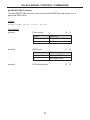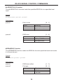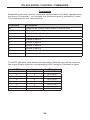
1
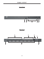
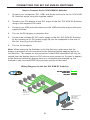
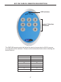
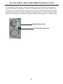
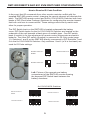
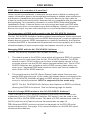
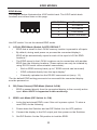
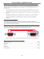
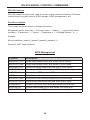
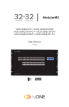
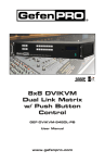
®
8x1 DVI KVM DL
Switcher
EXT-DVIKVM-841DL
User Manual
www.gefen.com
ASKING FOR ASSISTANCE
Technical Support:
Telephone
(818) 772-9100
(800) 545-6900
Fax(818) 772-9120
Technical Support Hours:
8:00 AM to 5:00 PM Monday through Friday, Pacific Time
Write To:
Gefen Inc.
c/o Customer Service
20600 Nordhoff St
Chatsworth, CA 91311
www.gefen.com
[email protected]
Notice
Gefen, LLC reserves the right to make changes in the hardware, packaging and
any accompanying documentation without prior written notice.
8x1 DVI KVM DL Switcher is a trademark of Gefen, LLC.
© 2014 Gefen, LLC., All Rights Reserved.
All trademarks are the property of their respective owners
Rev A8
CONTENTS
1Introduction
2
Operation Notes
3Features
4
Panel Layout
5
Panel Descriptions
6
Connecting the 8x1 DVI KVM DL Switcher
7
8x1 DVI KVM DL Remote Description
8
8x1 DVI KVM DL Switcher Remote Installation
9
RMT-8IR Remote and 8x1 DVI KVM Switcher Configuration
10 EDID Modes
12 DL (Dual Link) Only Modes
13 RS-232 Serial Communication
14 RS-232 Serial Control Commands
22 Rack Mount Installation
23 Specifications
24Warranty
INTRODUCTION
Congratulations on your purchase of the 8x1 DVI KVM DL Switcher. Your
complete satisfaction is very important to us.
Gefen
Gefen delivers innovative, progressive computer and electronics add-on solutions
that harness integration, extension, distribution and conversion technologies.
Gefen’s reliable, plug-and-play products supplement cross-platform computer
systems, professional audio/video environments and HDTV systems of all sizes
with hard-working solutions that are easy to implement and simple to operate.
The Gefen 8x1 DVI KVM DL Switcher
The rack-mountable Gefen 8x1 DVI KVM DL Switcher offers an economical
solution by eliminating the need to purchase many displays for each computer in
a studio or lab situation. A plug-and-play solution that supports both Macintosh
and IBM-PC computers, the 8x1 DVI KVM DL Switcher shares one DVI display
with up to eight computers or other DVI video sources. A single USB 2.0 port,
keyboard & mouse ports, and an analog audio jack are also switched. The
switcher saves space on your desktop by eliminating a crowded workspace full
of DVI monitors, keyboards & mice, and USB and audio cables. Switching of DVI
sources is easy and reliable.
How It Works
The DVI monitor is connected to the 8x1 DVI KVM DL Switcher’s output. Up to
eight DVI video sources connect to the switcher’s DVI inputs using included high
quality DVI cables. The included power supply is connected to the switcher via
the locking power plug and then to a power outlet. The currently selected DVI
video signal appears on the shared monitor. DVI Video sources (and optionally
keyboards and mice, USB and audio cables) are selected/switched using the
RMT-8IR remote control, RS-232 control, or the input selector push button on the
front panel of the switcher.
1
OPERATION NOTES
READ THESE NOTES BEFORE INSTALLING OR
OPERATING THE GEFEN 8X1 DVI KVM DL SWITCHER
•
The 8x1 DVI KVM DL Switcher will take any of up to eight (8) DVI dual-link or
single-link resolution inputs and switch them, one at a time, to a DVI output
device such as a display/monitor or projector. Dual link resolutions up to
3840 x 2400 are supported.
•
The 8x1 DVI KVM DL Switcher is housed in a metal box for better RF
shielding.
2
FEATURES
Features
•
Switches between any eight DVI Dual-link or Single-Link sources, with
USB 2.0 and analog audio to one display
•
Supports 1080p Full HD at 120Hz and dual-link resolutions up to 3840 x
2400 (WQUXGA) or single-link resolutions up to 1920 x 1200 (WUXGA)
•
Advanced EDID management
•
Saves space on your desktop
•
Use either PC or Mac USB keyboard/mouse
•
RS-232 port for automation
•
Switching is controlled via included IR remote, RS-232 commands,
or front-panel button
•
Supports DDWG standards for DVI monitors
•
Locking Power Supply
•
Rack-mountable
Package Includes
(1) 8x1 DVI KVM DL Switcher
(8) 6 ft. Dual Link DVI cables
(8) 6 ft. USB cables
(8) 6 ft. 3.5mm jack analog audio cables
(1) RMT-8IR Remote Control
(1) 5V / 4A DC locking power supply
(1) Set of rack ears
(1) Quick Start Guide
3
PANEL LAYOUT
Front Panel
1
2
4 5
3
Back Panel
10
6
11
7
4
12
9
8
PANEL DESCRIPTIONS
1
External IR Port
For connection of external IR extension device such as the Gefen IR Extender
(part # EXT-RMT-EXTIR).
2
IR Receiver
Receives IR signal from the handheld Infrared remote control unit included with
the 8x1 DVI KVM DL Switcher.
3
DVI Signal Status LEDs 1-8
Provide visual confirmation of the currently selected DVI input signal being
output to the DVI display device.
4
DVI Input Selector
Push-button switch cycles the next DVI input 1-8 in a forward sequence starting
again at 1.
5
Power Indicator LED
Indicates when the 8x1 DVI KVM DL Switcher is receiving 5V DC power from its
included AC power supply.
6
5V Locking Power Receptacle
Supplies power to the 8x1 DVI KVM DL Switcher from the included external 5V
DC power supply. The 5V power supply has a locking power tip which screws
into this receptacle.
7
DVI Input Ports 1-8
DVI video sources one through eight attach to the 8x1 DVI KVM DL Switcher.
8
DVI Output Port
This DVI output port is connected to the display device (Monitor, Projector).
9
RS-232 Serial Communications Interface
Provided for external control of the 8x1 DVI KVM DL Switcher.
10 3.5mm mini-Stereo Analog Audio Jacks 1-8
Audio Sources one through eight connect to the switcher here.
11 USB Type B Ports 1-8
USB devices one through eight connect to the switcher here.
12 USB Type A Control Ports 1-2
The keyboard & mouse for controlling the selected remote computer or device
connects to the switcher here.
5
CONNECTING THE 8X1 DVI KVM DL SWITCHER
How to Connect the 8x1 DVI KVM DL Switcher
1. Connect your computers’ DVI, USB, and Audio sources to the 8x1 DVI KVM
DL Switcher inputs using the supplied cables.
2. Connect your DVI display to the DVI output of the 8x1 DVI KVM DL Switcher
using a user-supplied DVI cable.
3. Connect your USB and audio devices to the USB and audio outputs with usersupplied cables.
4. Turn on the DVI display or projector first.
5. Connect the included 5V DC power supply to the 8x1 DVI KVM DL Switcher
by by screwing its 5V DC power supply tip into the receptacle in the rear of
the unit, then plug it into the wall.
6. Turn on the computer.
Note: When powering the Switcher on for the first time, make sure that the
display is powered on and connected to the Switcher before applying power to
the Switcher. The reason for this procedure is that EDID information will only be
copied from the display device to DVI sources upon power-up. If power is applied
to the Switcher before the display device is connected and powered up, the
Switcher’s last recorded EDID from previous activity will be used.
Wiring Diagram for the 8x1 DVI KVM DL Switcher
DVI DUAL LINK CABLE
AUDIO CABLE
USB CABLE
8x
DVI Dual Link Sources
USB Sources
Audio Sources
Switcher
DVI Dual Link Display
USB Keyboard
USB Mouce &
Powered Speaker
EXT-DVIKVM-841DL
6
8X1 DVI KVM DL REMOTE DESCRIPTION
LED Indicator
Input Selection
Buttons
The RMT-8IR remote control will allow the user to choose which of 8 DVI sources
or computers will be selected. Please use the information below when selecting the
desired source:
RMT-8IR Button
DVI Source
1
1
2
2
3
3
4
4
5
5
6
6
7
7
8
8
7
8X1 DVI KVM DL SWITCHER REMOTE INSTALLATION
To use the RMT-8IR remote, remove the battery cover on the back of the remote to
reveal the battery compartment. Insert the included battery into the open battery slot.
The positive (+) side should be facing up. Ensure that both DIP (Dual Inline Package)
switches are in the OFF position. Replace the battery cover. The remote ships with 2
batteries. One battery is needed for operation and the other battery is complimentary.
Empty Battery Slot
IR Code Dip Switches
8
RMT-8IR REMOTE AND 8X1 KVM SWITCHER CONFIGURATION
How to Resolve IR Code Conflicts
In the event that IR commands from other remote controls conflict with the
supplied RMT-8IR remote control, changing the remote channel will alleviate this
issue. The RMT-8IR remote control and the 8x1 DVI KVM DL Switcher both have
banks of DIP (Dual Inline Package) Switches for configuring the remote channel
that both units use to communicate. These settings must exactly match each
other for proper operation.
The DIP Switch bank on the RMT-8IR is located underneath the battery
cover. DIP Switch banks for the 8x1 DVI KVM DL Switcher are located on the
underside of the unit beneath a black piece of metallic tape. One DIP switch
bank (4-switch) is for the adjustment of remote control frequencies and switch
behavior. The other DIP switch (8-switch) is reserved for DL Only mode (page
11). Switches 1 and 2 on the RMT-8IR directly correspond to DIP Switches 1 and
2 on the 8x1 DVI KVM DL Switcher. Only switches 1 and 2 (of 4 in that bank) are
used for IR Code settings.
Remote Channel 1:
Default
Remote Channel 2:
1
2
Remote Channel 3:
1
2
1
2
Remote Channel 4:
1
2
Left: Picture of the opened rear battery
compartment of the RMT8-IR remote showing
the exposed DIP Switch bank between the
battery chambers.
8x1 DVI KVM DL Switcher
Remote Channel 1:
Default
Remote Channel 2:
1 2 3 4
1 2 3 4
Remote Channel 3:
Remote Channel 4:
1 2 3 4
1 2 3 4
9
EDID MODES
EDID. What is it, and what is it used for?
Under normal circumstances, a computer source device (digital or analog) will
require information about a connected device/display to assess what resolutions
and features (capabilities) are possible. The source device can then cater its
output to create resolutions and/or features that are compatible with the attached
device/display. This capability information is called EDID (Extended Display
Identification Data). A source device can only accept and read one EDID data
structure/record from a connected source device/display. Likewise, the source
device can output only one video resolution to a connected device/display.
The importance of EDID with regards to the 8x1 DVI KVM DL Switcher
The 8x1 DVI KVM DL Switcher handles multiple sources/inputs. Each connected
source device must correctly read one EDID data structure in order to address its
display device correctly. EDID management is carefully handled by the Switcher
to insure that EDID is recorded and retransmitted to sources properly at all times,
otherwise display of input sources might not happen correctly (or at all).
Managing EDID with the 8x1 DVI KVM DL Switcher
The 8x1 DVI KVM DL Switcher has 2 modes for routing EDID:
1. The default mode is the LOCAL mode which will store the EDID of a source
device (one for each input) into the 8x1 DVI KVM DL Switcher. The EDID
stored in each LOCAL location can be from a local display device or from
a remote source over the RS-232 serial communications port. The 8x1 DVI
KVM DL Switcher also includes a built-in EDID memory bank which can
store up to 7 separate EDID data structures which can then be loaded to
each of the LOCAL EDID locations.
2. The second mode is the DS (Down Stream) mode which functions as a
simple EDID pass-through. In this mode, the display device connected to the
8x1 DVI KVM DL Switcher will pass its EDID directly to whichever DVI input
source is currently selected. HDCP is supported in this mode only.
NOTE: The 8x1 DVIKVM DL/SL Switcher also features an EDID Lock Mode,
allowing the EDID to be stored. See the following page for details.
How do I change EDID modes in the 8x1 DVI KVM DL Switcher?
There is an bank of 4 DIP switches located on the main circuit board on the
underside of the 8x1 DVI KVM DL Switcher. DIP switch 3 can be used to set
either the DS or LOCAL EDID modes. The bank of 8 DIP switches are used for
the DL (dual link) only feature and are discussed later on page 12.
TIP: Advanced EDID functions can also be managed via the RS-232 serial
communications port. See page 13 for more information on the RS-232 serial
communication features.
10
EDID MODES
EDID Modes
The diagram below illustrates the 4 DIP switch bank. The 8 DIP switch bank
functions are outlined later on this page.
DIP SWITCH
Function
1
IR Channel
2
IR Channel
3
EDID Mode
4
EDID Lock Mode
1 2 3 4
Use DIP switch 3 to set the desired EDID mode.
1. LOCAL EDID Mode (Switch 3=OFF) DEFAULT
• EDID that is stored in the LOCAL memory location is passed to all inputs.
•
By default, during each power on process the connected display’s
EDID will be automatically copied to each of the input’s LOCAL EDID
locations.*
•
The EDID stored in the LOCAL locations can be overwritten with another
EDID from the following locations (These options can only be initiated by
using RS-232 serial communication commands) :
•
Built-in EDID memory bank (up to 7 EDID records can be stored)
•
EDID collected directly from the input display*
•
Externally uploaded via the RS-232 command set (see p. 13)
*For the default EDID writing process to be successful the connected display
must be powered on.
2. DS (Down Stream) EDID Mode (Switch 3=ON)
•
EDID is passed directly from the connected display to the currently active
input. Note: HDCP is supported in this mode only.
3. EDID Lock Mode (DIP Switch 4 = ON)
•
Locks the last stored EDID, even if the unit is power-cycled. To store a
new EDID, do the following:
1. Power-down the Switcher and set DIP Switch 4 to the OFF position.
2. Connect the display to the DVI output port then power-on the Switcher.
3. Set DIP Switch 4 to the ON position to lock the EDID.
11
DL (DUAL LINK) ONLY MODES
DL (Dual Link) Only Modes
The 8 DIP switch bank, located on the underside of the 8x1 DVI KVM DL
Switcher cab be used to set each individual input to work in a Dual Link Only
mode. These modes should only be enabled if issues occur when using Dual
Link sources and displays in the default mode.
DIP SWITCH
Function
DIP SWITCH
Function
1
Input 1 Mode
5
Input 5 Mode
2
Input 2 Mode
6
Input 6 Mode
3
Input 3 Mode
7
Input 7 Mode
4
Input 4 Mode
8
Input 8 Mode
Use DIP switch 3 to set the desired EDID mode.
DL (Dual Link) and SL (Single Link) Mode (Switch=OFF) DEFAULT
• This setting can be set individually for each input. This mode will allow
the connection of both Dual Link and Single Link displays.
DL (Dual Link) Only Mode (Switch=ON)
• This setting can be set individually for each input. This mode should be
enabled if issues with the default occur with Dual Link displays.
12
RS-232 SERIAL COMMUNICATION
What features are available via the RS-232 serial communications port?
The 8x1 DVI KVM DL Switcher can accept commands through the RS-232 serial
communications port located on the rear panel. The current RS-232 control
features are:
•
Switching/routing of inputs to outputs without the RMT-8IR remote control.
•
Switch EDID modes without operating the DIP switches on the underside of
the unit.
•
Managing the EDID bank and EDID that is loaded into the LOCAL EDID.
•
Upload new EDID’s to the EDID bank or directly to the LOCAL EDID
location.
How do I use these features?
These features were initially intended for utilization by custom installers in
automated setups. However, these features can be tested by using any computer
with a terminal emulation program.
What pins are used for communication with the 8x1 DVI KVM DL Switcher?
Only pins 2 (Receive), 3 (Transmit), and 5 (Ground) are used for communication.
A null-modem adapter should not be used with this product.
54321
12345
9876
6789
Only Pins 2 (RX), 3 (TX), and 5 (Ground) are used on the RS-232 serial interface
What are the communication port settings?
Bits per second ............................................................................................ 19200
Data bits ............................................................................................................... 8
Parity ............................................................................................................. None
Stop bits ................................................................................................................1
Flow Control .................................................................................................. None
13
RS-232 SERIAL CONTROL COMMANDS
RS-232 Features
RS-232 remote functions are used to control of this product’s features. Features
include input to output routing, EDID storage, EDID management, etc.
Functions Syntax
The syntax for each function is always the same:
#Character as the start flag → Function name → Space ( _ ) as function name
end flag → Parameter 1 → Space → Parameter n → Carriage Return ( \r ) →
Sample:
#FunctionName_param1_param2_param3_param4...\r
Syntax is NOT case sensitive.
EDID Management
Function
Description
#EDIDDSTOLO
Read downstream EDID and stores into all inputs
#EDIDDSTOBA
Read downstream EDID and stores in EDID Bank
#EDIDBATOLO
Read from EDID bank and store into all local inputs
#DDCTODS
Route input DDC to downstream EDID (pass-through mode)
#DDCTOLO
Routes input DDC to local EDID
#DEF
Sets unit to default factory settings
#LOEDIDTOBA
Load EDID from serial port and store in EDID bank
#LOEDIDTOLO
Loads EDID from serial port and store in any input
#PRBAEDID
Reads EDID from EDID bank and sends to serial port
#PRDSEDID
Reads downstream EDID and sends it to serial port
#PRLOEDID
Reads local input EDID and sends it to serial port
14
RS-232 SERIAL CONTROL COMMANDS
#EDIDDSTOLO Function
The #EDIDDSTOLO function reads the downstream EDID and stores into all local inputs.
Syntax:
#EDIDDSTOLO
Parameters:
None
#EDIDDSTOBA Function
The #EDIDDSTOBA function reads the downstream EDID and stores it to a
specified EDID bank.
Syntax:
#EDIDDSTOBA param1
Parameters:
param1
EDID bank offset
[1 - 7]
#EDIDBATOLO Function
The #EDIDBATOLO function reads an EDID from an EDID bank and stores it in
all inputs.
Syntax:
#EDIDBATOLO param1
Parameters:
param1
EDID bank offset
15
[1 - 7]
RS-232 SERIAL CONTROL COMMANDS
#DDCTODS Function
The #DDCTODS function routes the input DDC to the downstream EDID (passthrough mode).
Syntax:
#DDCTODS
Parameters:
None
#DDCTOLO Function
The #DDCTOLO function routes the input DDC to the local EDID.
Syntax:
#DDCTOLO
Parameters:
None
#DEF Function
The #DEF function set the Switcher to the factory default settings.
Syntax:
#DEF
Parameters:
None
16
RS-232 SERIAL CONTROL COMMANDS
#LOEDIDTOBA Function
The #LOEDIDTOBA function loads the specified EDID file and stores it in a
specified EDID bank.
Syntax:
#LOEDIDTOBA param1 param2 param3
Parameters:
param1
param2
param3
Echo mode
Value
Meaning
0
Semi echo mode
1
Full echo mode
EDID size
Value
Meaning
1
128 byte EDID
2
256 byte EDID
EDID bank offset
17
[0 - 1]
[1 - 2]
[1 - 7]
RS-232 SERIAL CONTROL COMMANDS
#LOEDIDTOLO Function
The #LOEDIDTOLO function loads the specified EDID file to a specified local
input.
Syntax:
#LOEDIDTOLO param1 param2
Parameters:
param1
param2
Echo mode
Value
Meaning
0
Semi echo mode
1
Full echo mode
EDID size
Value
Meaning
1
128 byte EDID
2
256 byte EDID
[0 - 1]
[1 - 2]
#PRBAEDID Function
The #PRBAEDID function reads the EDID file from the specified bank and sends
it to the serial port.
Syntax:
#PRBAEDID param1 param2
Parameters:
param1
EDID bank offset
[1 - 7]
param2
File type
[0 - 1]
Value
Meaning
0
.BIN file
1
.TXT file
18
RS-232 SERIAL CONTROL COMMANDS
#PRDSEDID Function
The #PRDSEDID function reads the downstream EDID and sends it to the serial
port.
Syntax:
#PRDSEDID param1
Parameters:
param1
File type
Value
Meaning
0
.BIN file
1
.TXT file
[0 - 1]
#PRLOEDID Function
The #PRLOEDID function reads the local EDID and spools it to the serial port.
Syntax:
#PRLOEDID param1
Parameters:
param1
File type
Value
Meaning
0
.BIN file
1
.TXT file
19
[0 - 1]
RS-232 SERIAL CONTROL COMMANDS
Commands
Simplified syntax was used for command implementation for faster operation with
the device: # character – isn’t needed, the command name is reduced to 1 letter.
The commands are not case-sensitive.
Command
Description
M
Displays the current matrix status in tabular form
P
Displays the function menu
1
Switch to Input 1
2
Switch to Input 2
3
Switch to Input 3
4
Switch to Input 4
5
Switch to Input 5
6
Switch to Input 6
7
Switch to Input 7
8
Switch to Input 8
The ASCII character table below indicates which Switcher input will be routed to
the output Display when the corresponding ASCII (numeric) character is typed.
ASCII
1
2
3
4
5
6
7
8
Input
1
2
3
4
5
6
7
8
Binary
0011 0001
0011 0010
0011 0011
0011 0100
0011 0101
0011 0110
0011 0111
0011 1000
20
RS-232 SERIAL CONTROL COMMANDS
2. USING SHORT-CUT CHARACTERS TO CHANGE SETTINGS
2.1 HYPERTERMINALtm SETTINGS in Microsoft Windowstm
First, please setup correct communications by performing these commands (as
shown on the screen shot immediately below):
File->Properties->Setting->ASCII Setup
Also, please be sure to unmark the check box that says “Send line ends with line
feeds.”
2.2 EXAMPLE -- CHANGE THE ROUTED SOURCE
Now you are ready to route Display input sources.
At the Hyperterminal cursor prompt, type the numeral key of the input to switch
to, followed by the ENTER key.
Wait until you see the message “Function Done” on the Display. At this point the
Display should show the correct Source corresponding to the numeral that was
typed.
21
RACK MOUNT INSTALLATION
Rack mount ears are provided for installation of this unit into a 1U rack mount
space.
1.
2.
3.
4.
Locate the side screws on the unit.
Remove the front 2 screws that are located closest to the front of the unit.
Using the removed screws, screw the rack mounting bracket into the unit.
Repeat the procedure on the opposite side of the unit.
1
Front of unit
Rear of unit
2
3
4
22
SPECIFICATIONS
Video Amplifier Bandwidth...................................................................165 MHz x 2
Input Video Signal................................................................................1.2 Volts p-p
Input DDC Signal...........................................................................5 Volts p-p (TTL)
DVI Connector..................................................... DVI-I 29-pin female (digital only)
USB Input Connection................................................................................Type “B”
USB Output Connection.............................................................................Type “A”
Audio Connector..................................................... 3.5mm mini-Stereo phone jack
Power Supply..................................................................................5V / 4A, locking
Power Consumption......................................12.5 Watts (min.) / 32.5 Watts (max.)
Dimensions.......................................................................17.1” W x 1.8” H x 4.2” D
Rack-mountable..............................................................................1U Rack Space
Shipping Weight............................................................................................12 lbs.
Specifications are subject to change without notice.
23
WARRANTY
Gefen warrants the equipment it manufactures to be free from defects in material
and workmanship.
If equipment fails because of such defects and Gefen is notified within two (2)
years from the date of shipment, Gefen will, at its option, repair or replace the
equipment, provided that the equipment has not been subjected to mechanical,
electrical, or other abuse or modifications. Equipment that fails under conditions
other than those covered will be repaired at the current price of parts and labor in
effect at the time of repair. Such repairs are warranted for ninety (90) days from
the day of reshipment to the Buyer.
This warranty is in lieu of all other warranties expressed or implied, including
without limitation, any implied warranty or merchantability or fitness for any
particular purpose, all of which are expressly disclaimed.
1. Proof of sale may be required in order to claim warranty.
2. Customers outside the US are responsible for shipping charges to and from
Gefen.
3. Copper cables are limited to a 30 day warranty and cables must be in their
original condition.
The information in this manual has been carefully checked and is believed to
be accurate. However, Gefen assumes no responsibility for any inaccuracies
that may be contained in this manual. In no event will Gefen be liable for
direct, indirect, special, incidental, or consequential damages resulting from
any defect or omission in this manual, even if advised of the possibility of such
damages. The technical information contained herein regarding the features and
specifications is subject to change without notice.
For the latest warranty coverage information, refer to the Warranty and Return
Policy under the Support section of the Gefen Web site at www.gefen.com.
PRODUCT REGISTRATION
Please register your product online by visiting the Register Product page
under the Support section of the Gefen Web site.
24
Rev A8
20600 Nordhoff St., Chatsworth CA 91311
1-800-545-6900
818-772-9100
www.gefen.com
Pb
This product uses UL listed power supplies.
fax: 818-772-9120
[email protected]