1
Fujitsu Semiconductor Europe
User Manual
FSEUGCC-UM_SK-86R12-01_Rev1.4
EMERALD-P
PROMOTION BOARD
SK-86R12-01
USER MANUAL
Emerald-P Promotion Board
SK-86R12-01
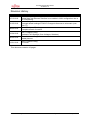
Revision History
Date
15.10.2012
21.05.2012
Issue
Rev1.4 Andy von Treuberg
Added Note that Ethernet Interface is not usable in WAV configuration due to
pin multiplexing.
Rev1.3 Andy von Treuberg
Changed default settings of SW15. Changed references to schematic (now
Rev1.7)
08.05.2012
Rev1.2 Andy von Treuberg
Complete rework of content.
16.04.2012
Rev1.1 Herbert Hönig
Updated JTAG Settings (Core Voltages, Switches)
02.02.2012
Rev1.0 Herbert Hönig
Added pictures
13.01.2012
Rev0.1 Herbert Hönig
First draft
This document contains 42 pages.
FSEUGCC-UM_SK86R12-01-Rev1.4
-2-
© Fujitsu Semiconductor Europe GmbH
Emerald-P Promotion Board
SK-86R12-01
Trademarks
APIX™ is a registered trademark of Inova Semiconductors GmbH, Grafinger Str. 26, 81671
Munich, Germany
ARM™ is a registered trademark of ARM Limited in UK, USA and Taiwan.
ARM™ is a trademark of ARM Limited in Japan and Korea.
ARM Powered™ logo is a registered trademark of ARM Limited in Japan, UK, USA, Korea
and Taiwan.
PrimeCell® is owned by ARM Limited.
CAN®, Controller Area Network® are registered trademarks of Bosch Corporation in the
United States and other countries.
I2C® is a registered trademark of Philips Semiconductor Corporation in the United States
and other countries.
SPI®, Serial Peripheral Interface, is a registered trademark of Motorola Corporation in the
United States and other countries.
RSDS® and PPDS® are registered trademarks of National Semiconductor.
Truevision® is a registered trademark of Truevision, Inc.
TGA® is a trademark of Truevision, Inc.
Other system names or product names which may appear in this document are the
trademarks of the respective company or organization.
FSEUGCC-UM_SK86R12-01-Rev1.4
-3-
© Fujitsu Semiconductor Europe GmbH
Emerald-P Promotion Board
SK-86R12-01
Warranty and Disclaimer
To the maximum extent permitted by applicable law, Fujitsu Semiconductor Europe GmbH restricts its
warranties and its liability for all products delivered free of charge (eg. software include or header
files, application examples, target boards, evaluation boards, engineering samples of IC’s etc.), its
performance and any consequential damages, on the use of the Product in accordance with (i) the
terms of the License Agreement and the Sale and Purchase Agreement under which agreements the
Product has been delivered, (ii) the technical descriptions and (iii) all accompanying written materials.
In addition, to the maximum extent permitted by applicable law, Fujitsu Semiconductor Europe GmbH
disclaims all warranties and liabilities for the performance of the Product and any consequential
damages in cases of unauthorised decompiling and/or reverse engineering and/or disassembling.
Note, all these products are intended and must only be used in an evaluation laboratory
environment.
1.
Fujitsu Semiconductor Europe GmbH warrants that the Product will perform substantially in
accordance with the accompanying written materials for a period of 90 days form the date of
receipt by the customer. Concerning the hardware components of the Product, Fujitsu
Semiconductor Europe GmbH warrants that the Product will be free from defects in material
and workmanship under use and service as specified in the accompanying written materials
for a duration of 1 year from the date of receipt by the customer.
2.
Should a Product turn out to be defect, Fujitsu Semiconductor Europe GmbH´s entire liability
and the customer´s exclusive remedy shall be, at Fujitsu Semiconductor Europe GmbH´s sole
discretion, either return of the purchase price and the license fee, or replacement of the
Product or parts thereof, if the Product is returned to Fujitsu Semiconductor Europe GmbH in
original packing and without further defects resulting from the customer´s use or the transport.
However, this warranty is excluded if the defect has resulted from an accident not attributable
to Fujitsu Semiconductor Europe GmbH, or abuse or misapplication attributable to the
customer or any other third party not relating to Fujitsu Semiconductor Europe GmbH.
3.
To the maximum extent permitted by applicable law Fujitsu Semiconductor Europe GmbH
disclaims all other warranties, whether expressed or implied, in particular, but not limited to,
warranties of merchantability and fitness for a particular purpose for which the Product is not
designated.
4.
To the maximum extent permitted by applicable law, Fujitsu Semiconductor Europe GmbH´s
and its suppliers´ liability is restricted to intention and gross negligence.
NO LIABILITY FOR CONSEQUENTIAL DAMAGES
To the maximum extent permitted by applicable law, in no event shall Fujitsu
Semiconductor Europe GmbH and its suppliers be liable for any damages whatsoever
(including but without limitation, consequential and/or indirect damages for personal
injury, assets of substantial value, loss of profits, interruption of business operation,
loss of information, or any other monetary or pecuniary loss) arising from the use of
the Product.
Should one of the above stipulations be or become invalid and/or unenforceable, the remaining
stipulations shall stay in full effect
FSEUGCC-UM_SK86R12-01-Rev1.4
-4-
© Fujitsu Semiconductor Europe GmbH
Emerald-P Promotion Board
SK-86R12-01
Table of Contents
1
Introduction ........................................................................................................ 7
1.1
System Features ................................................................................................... 7
1.2
Mechanical Dimensions ....................................................................................... 8
2
Information and Support on the Internet ......................................................... 9
3
System Overview ............................................................................................. 10
4
Quickstart ......................................................................................................... 11
5
About U-Boot ................................................................................................... 13
6
Board Layout.................................................................................................... 14
7
Board Configuration DIP Switches ................................................................ 15
7.1
DIP Switch SW10 (JTAG, Pin Multiplex Mode) .................................................. 15
7.2
DIP Switch SW15 (Boot Flash Selection, PLL, Exception Vectors) ................. 16
7.3
Bootstrap Options and Flash Configuration ..................................................... 18
7.4
Interfaces Configuration..................................................................................... 20
8
Interfaces .......................................................................................................... 22
8.1
Display Outputs .................................................................................................. 22
8.1.1
8.1.2
8.1.3
8.2
Display Outputs HDMI (2 available) .............................................................................. 22
Display Outputs via Pin Headers (also for Glyn TFT family displays) .......................... 24
Display Output via APIX™ TX (3GBit) .......................................................................... 25
Video Capture Interfaces .................................................................................... 25
8.2.1
8.2.2
8.2.3
8.2.4
8.2.5
Capture via APIX RX (RGB888) 3GBit Link .................................................................. 25
Capturing via HDMI (RGB888) ...................................................................................... 25
Capturing Video via Pin Header X34 (RGB888) ........................................................... 25
Capturing Video (ITU656) ............................................................................................. 26
Video Capture for 360° Wrap Around View (using all 4 capture units) ........................ 26
8.3
Ethernet (using internal MAC, external PHY) .................................................... 27
8.4
USB Host Interface ............................................................................................. 27
8.5
JTAG / 16 Bit Trace Interface ............................................................................. 27
8.6
Mini-USB to RS232 / HOST SPI / I2C Interface ................................................... 28
8.6.1
8.6.2
8.6.3
HOST SPI Interface....................................................................................................... 28
RS232 (UART) Ports ..................................................................................................... 28
2
I C Interface .................................................................................................................. 29
8.7
CAN Interface ...................................................................................................... 29
8.8
MediaLB Interface ............................................................................................... 29
8.9
SD Card Interface ................................................................................................ 29
8.10
Sound .................................................................................................................. 30
8.11
AIC / IPC (to Atlas) .............................................................................................. 30
9
Power Supply ................................................................................................... 32
9.1
10
External Startup .................................................................................................. 32
Memory.......................................................................................................... 33
FSEUGCC-UM_SK86R12-01-Rev1.4
-5-
© Fujitsu Semiconductor Europe GmbH
Emerald-P Promotion Board
SK-86R12-01
10.1
DDR3 (U27, U28).................................................................................................. 33
10.2
QUAD SPI Flash (U40) ........................................................................................ 33
10.3
NAND Flash (U39) ............................................................................................... 33
10.4
NOR Flash (U34, U35) ......................................................................................... 33
10.4.1
Overview of possible Use Configurations ..................................................................... 34
11
360°Wrap Around View (WAV) System ....................................................... 35
12
Appendix ....................................................................................................... 41
12.1
Literature and References Used ........................................................................ 41
12.2
Figures................................................................................................................. 42
FSEUGCC-UM_SK86R12-01-Rev1.4
-6-
© Fujitsu Semiconductor Europe GmbH
Emerald-P Promotion Board
SK-86R12-01
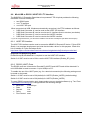
1 Introduction
1.1
System Features
This section provides an overview of the features of the SK-86R12-01 (Emerald-P Promotion
Board).
2x RS232 interfaces via FTDI USB serial converter (USB to RS232)
HOST SPI interface via FTDI USB serial converter (USB to HOST SPI)
CAN interface (Pin header 2.54 mm)
Media LB interface 3 pin ( Pin header 1.27 mm)
MOST interface connector for SMSC PHY + Modules
AIC / IPC interface (designed to work with Fujitsu ATLAS/Calypso MCU boards)
DDR3 DRAM 2x 2GBit (512 MByte)
NOR Flash 16 bit or 32 bit usable (2 GBit)
NAND Flash 16 bit length (2 GBit)
Quad SPI Flash (128 MBit) on board
Ethernet (internal MAC of Emerald used, external PHY) 10/100 MBit Configuration
1x USB Host
JTAG debugger connector (38 pin Mictor Connector) (20 pin, 2.54 mm pitch adapter
available)
SD card interface
3x APIX TX interfaces (3 Gbit)
1x APIX RX interface (3 Gbit)
4x cinch (YUV) and 4x S-Video connectors for video input
HDMI video capture input (RGB888)
2x HDMI video output (RGB888)
1x FFC video output (RGB666) with touch controller (for the direct connection of Glyn
EDT display family devices)
3x video output on pin header 1.27mm pitch (RGB888)
3x user buttons and 3x user LEDs (programmable via GPIOs)
Sound line input / line output
Connector for SK-86R12-WAV01 (add-on board for digital 360° wrap around view
cameras)
Most of the interfaces can be accessed separately via control switches on the board. This
makes it possible to use all the multiplex modes that MB86R12 'Emerald-P' provides.
FSEUGCC-UM_SK86R12-01-Rev1.4
-7-
© Fujitsu Semiconductor Europe GmbH
Emerald-P Promotion Board
SK-86R12-01
1.2
Mechanical Dimensions
-
PCB (components not mounted): 200 x 150 mm
-
Dimensions with mounted connectors: 220 x 150 mm
-
Height (with spacing bolts): 40 mm
FSEUGCC-UM_SK86R12-01-Rev1.4
-8-
© Fujitsu Semiconductor Europe GmbH
Emerald-P Promotion Board
SK-86R12-01
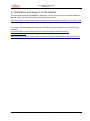
2 Information and Support on the Internet
The functional details of the MB86R12 'Emerald-P' device can be found in the latest Hardware
Manual, which can be downloaded from the following location:
http://www.fujitsu.com/emea/services/microelectronics/gdc/gdcdevices/mb86r12-emerald-p.html
(select the 'Support' tab).
For support and downloads concerning the SK-86R12-01 board, please refer to the following
locations:
http://www.fujitsu.com/emea/services/microelectronics/gdc/evalbds/emerald-ppromotionboard.html (select the 'Support' tab) or
http://www.fujitsu.com/emea/services/microelectronics/gdc/evalbds/wraparound-starterkit.html
(select the 'Support' tab).
FSEUGCC-UM_SK86R12-01-Rev1.4
-9-
© Fujitsu Semiconductor Europe GmbH
Emerald-P Promotion Board
SK-86R12-01
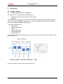
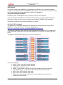
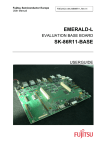
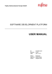
3 System Overview
The Emerald-P Promotion Board itself is a complete evaluation system, but there are also two
optional extras that can be used in conjunction with the Promotion Board to build a system for
specific application development.
•
Emerald-P Promotion Board (SK-86R12-01)
•
Optional extra: SK-86R12-WAV01 (add-on board for digital 360° wrap around view
providing 4x digital camera support)
•
Optional extra: MOST add-on Board (SMSC PHY+ series)
Figure 3-1: System Overview
The Emerald-P Promotion Board is also a part of the 360° Wrap Around View product and is
therefore also covered in this guide.
FSEUGCC-UM_SK86R12-01-Rev1.4
- 10 -
© Fujitsu Semiconductor Europe GmbH
Emerald-P Promotion Board
SK-86R12-01
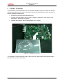
4 Quickstart
Before powering up the board, please ensure that
•
you have a DC power supply that can deliver a voltage in the range 9 ... 18V (12V
recommended) at max. 1.5A. The inner pin has to be connected to positive (+), the outer
ring has to be connected to ground (-). A suitable power supply can also be delivered by
Fujitsu (please contact your Fujitsu Sales Representative if required).
•
all the switch settings on the board (e.g. pin multiplex settings, interfaces to be used) are
correct for your application. The default settings of the switches are described in this
document.
To bring the system into operation quickly, execute the following steps:
•
Install the drivers for the FTDI components on your board, either by obtaining the latest
version from the FTDI website* or from the WAV Tools DVD (e.g. E:\Driver\CDM 2.08.24
WHQL Certified)
* http://www.ftdichip.com/Drivers/VCP.htm
http://www.ftdichip.com/Support/Documents/InstallGuides.htm
•
Connect a mini USB cable to J1 and the other end to your PC.
The SK86R12-01 Promotion Board will be automatically recognized and four new COM
ports will be installed as follows:
o
'USB Serial Converter A': can be used as the HOST SPI interface
o
'USB Serial Converter B': can be used as an I2C interface direct to devices
o
'USB Serial Converter C': can be used as the UART0 interface
o
'USB Serial Converter D': can be used as the UART4 interface
Note that Windows may not use exactly these names, however, the third COM port
installed is the one that is required for the next installation step.
•
Start a terminal program such as Tera Term (http://ttssh2.sourceforge.jp) with the
following configuration:
o
Baud rate: 115.200 bps
o
Data:
o
Stop bit:
o
Parity:
o
Flow Control: none
8 bits
1 bit
none
•
Connect the terminal program to port: 'USB Serial Converter C'
•
Connect an HDMI cable to X1 (use the upper HDMI port of the connector - which is
Display 0). Connect the other end of the cable to a TFT monitor that supports DVI and a
resolution of 800 x 480 pixels (virtually any modern TFT monitor will support this mode).
•
Connect the external DC power supply to X22 (at 12V a current of around 600 mA will
be needed in power up mode)
•
Switch on your SK86R12-01 Promotion Board using switch SW9 (large switch on the
bottom right-hand corner of the PCB), and check that LEDs D6, D7 and D8 light up.
FSEUGCC-UM_SK86R12-01-Rev1.4
- 11 -
© Fujitsu Semiconductor Europe GmbH
Emerald-P Promotion Board
SK-86R12-01
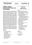
•
After the board has powered up, the embedded Linux operating system is started and a
demonstration program will be run (this can take a number of seconds). Please monitor
the messages in the terminal console window for any errors or warnings.
•
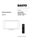
After the system has completed booting, a dashboard demonstrator will be shown on the
display.
Figure 4-1: Console output
Figure 4-2: Running Demo
FSEUGCC-UM_SK86R12-01-Rev1.4
- 12 -
© Fujitsu Semiconductor Europe GmbH
Emerald-P Promotion Board
SK-86R12-01
5 About U-Boot
The U-Boot utility is an embedded program that handles the basic configuration of the
MB86R12 device, boots the Linux operating system and provides a communication interface to
the user. Assuming the physical connection has been made from the PC (USB interface) to the
SK86R12-01 (USB) and the board has been self-installed (creating a new virtual COM ports,
e.g. for communication), the U-Boot program presents itself to a user via a terminal program link
which uses the third new virtual COM port (may be named 'USB Serial Converter C').
To stop U-Boot loading the demonstration program, press any key on your keyboard (quickly)
after a board reset (SW4) or power on (SW9).
Using specific commands, the configuration of the MB86R12 can be queried ('printenv'
command on the command prompt of the terminal program) and configured (using the 'setenv'
command). To set up a new pin multiplex configuration for example, check the values returned
for the pinmux and pinmux2 environment variables using the command printenv on the
command line prompt, then change the configuration using (for example):
setenv pinmux 84000000
setenv pinmux2 00000000
saveenv
The U-Boot utility is described in detail in the documentation provided with the SK86R12-01
board. Please check the 'Software Development Platform' document (at the time this User
Manual was written, this document was named
um-MB86R11-SoftwareDevelopmentPlatform.pdf
and was located in the root folder of the downloadable Linux BSP (UpdateHost_v3.2.0.zip).
FSEUGCC-UM_SK86R12-01-Rev1.4
- 13 -
© Fujitsu Semiconductor Europe GmbH
Emerald-P Promotion Board
SK-86R12-01
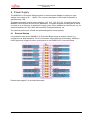
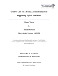
6 Board Layout
In the standard delivery form, the board's layout is as shown in the diagram below.
Figure 6-1: Standard Board Layout/Assembly
FSEUGCC-UM_SK86R12-01-Rev1.4
- 14 -
© Fujitsu Semiconductor Europe GmbH
Emerald-P Promotion Board
SK-86R12-01
7 Board Configuration DIP Switches
The Emerald-P Promotion Board is configured using a series of DIP switches. The functionality
of these groups of switches is described in the following sections.
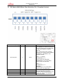
7.1
DIP Switch SW10 (JTAG, Pin Multiplex Mode)
Part Number (Group)
Switch
Switch Name
SW10 (System)
1
-
Unused (leave OFF)
2
-
Unused (leave OFF)
3
-
Unused (leave OFF)
4
JTAG Select
5
MPXMODE 0
6
MPXMODE 1
7
MPXMODE 2
8
TEST MODE
Function
Connected to the JTAGSEL pin of
MB86R12.
0 = Normal Mode (JTAG interface not in
use, default)
1 = DFT (Design For Test) Mode
Connected to the MPXMODE[0,1,2] pins
of MB86R12. The functionality of these
pins is somewhat complex – please refer
to the section 'Pin Multiplexing' of the
MB86R12 Hardware Manual.
Default setting: Mode 2.
Reserved – do not change!
0 = Normal Mode (default)
1 = Test Mode
SW10 can be found on page 8 of the schematic (Rev1.7).
FSEUGCC-UM_SK86R12-01-Rev1.4
- 15 -
© Fujitsu Semiconductor Europe GmbH
Emerald-P Promotion Board
SK-86R12-01
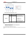
7.2
DIP Switch SW15 (Boot Flash Selection, PLL, Exception Vectors)
Part Number (Group)
Switch
Switch Name
Function
Connected to the SELFL (Select Flash)
pin of MB86R12 to select the memory to
boot from (please refer to the 'Boot Strap'
chapter of the MB86R12 Hardware
Manual).
Note: The boot flash device selected
depends on the setting of SELFL and the
MPXMODE 0 / MPXMODE 1 DIP
switches of SW10!
SW15 (System)
1
SELFL
SELFL = 0: (default)
MPXMODE[1:0] = 11:
System boots from Serial flash
MPXMODE[1:0] = any other setting:
System boots from NOR flash
SELFL = 1:
MPXMODE[1:0] = 11:
Reserved
MPXMODE[1:0] = any other setting:
System boots from NAND flash
2
CRIPM0
3
CRIPM1
4
CRIPM2
5
CRIPM3
FSEUGCC-UM_SK86R12-01-Rev1.4
- 16 -
The combined state of these switches
sets the initial value of the SSCG
feedback divider ratio (please refer to the
section 'PLL Setting' of the MB86R12
Hardware Manual).
© Fujitsu Semiconductor Europe GmbH
Emerald-P Promotion Board
SK-86R12-01
6
7
8
PLLBYPASS
Configures the PLL bypass function
(please refer to the section 'PLL Bypass'
and 'PLL Operating Frequency' of the
MB86R12 Hardware Manual).
0 = PLL is not bypassed (default)
1 = PLL is bypassed
PSMODE
Configures the initial value of the PLL
clock frequency divider ratio (please refer
to the section 'PLL Operating Frequency'
of the MB86R12 Hardware Manual).
0 = 533 MHz (default)
1 = 400 MHz
Please read the important note below
concerning the use of PSMODE!
VINITH
Connected to the VINITHI line of the
ARM core which determines the starting
address of the exception vectors.
0 = exception vectors are located at
0x0000_0000 (default)
1 = exception vectors are located at
0xFFFF_0000
Important Note
(For Board Owners with an MB86R12 up to ES2 (Engineering Samples, Step 2*)
To use the JTAG interface with the Fujitsu 'Developer Suite' tool, you must set the PSMODE
switch to “OFF” (= binary value 1), enabling reliable use of the JTAG interface. If you are using
a different tool (e.g. GHS Integrity or RealView, then the PSMODE switch can be set to 'ON'.
* To check which ES you have, please look at the date code on the package, or check the chip's
ID (register)
ES1
Emerald-P
ES2
Data code
CCID
Date Code
CCID
1132
865212F1
1150
865212F2
Please check also board schematics page 8.
Summarizing the default DIP switch configuration shown above for SW10 and SW15; the board
is configured to run at 533 MHz and software can be uploaded via Ethernet.
SW10 can be found on page 8 of the schematic (Rev1.7).
FSEUGCC-UM_SK86R12-01-Rev1.4
- 17 -
© Fujitsu Semiconductor Europe GmbH
Emerald-P Promotion Board
SK-86R12-01
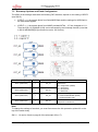
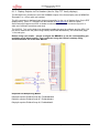
7.3
Bootstrap Options and Flash Configuration
The effect of the settings made with the following DIP switches, depend on the setting of SELFL
(see SW15).
•
If SELFL = 0, the system boots from Serial/NOR flash and the settings for NOR flash in
the table below applies.
•
If SELFL = 1, the system boots from NAND provided INTA4 ... A7 are changed to 1111.
Then the 2Gb, 16 bit NAND (U39) can be accessed by the bootstrap function (note that
in SW10 MPXMODE[2:0] must also be set to 100 for this).
Part Number (Group)
Switch
Switch Name
Function
Sets the operation mode of the serial
flash device:
00 = Single Mode (default)
01 = Dual Mode
10 = Quad Mode
11 = Reserved
SW11 (NOR Flash)
1
INT_A4
SW12 (NOR Flash)
1
INT_A5
SW13 (NOR Flash)
1
INT_A6
Sets the memory type in use:
0 = Winbond W25Q16BV (default)
1 = Spansion S25FL129P
SW14 (NOR Flash)
1
INT_A7
Reserved, default = 0.
(Required for NAND boot)
Note:
To change the settings of a switch, you must first remove the thin protective yellow foil on the
top of the switch body.
SW11 .. 14 can be found on page 8 of the schematic (Rev1.7).
FSEUGCC-UM_SK86R12-01-Rev1.4
- 18 -
© Fujitsu Semiconductor Europe GmbH
Emerald-P Promotion Board
SK-86R12-01
Part Number (Group)
Switch
Switch Name
SW5 (NOR Flash)
1
32 Bit Mode /
16 Bit Mode
SW8 (NOR Flash)
1
Device/Use Mode
Function
Sets the type of serial flash device:
1 - 2 = 32 Bit Flash
2 - 3 = 16 Bit Flash (default)
Interacts with SW5. Sets the use mode
for components U34/U35 (see
schematic)
1 - 2 = Use U35 in 16 Bit mode
2 - 3 = Use U34 in 16 bit mode / U34 +
U35 in 32 Bit mode (default)
Summarizing, the default configuration of the system is:
•
•
Boot from NOR flash
Use component U34 in 16 Bit mode
Please check the board schematics on pages 2 and 8.
Note:
To change the settings of a switch, you must first remove the thin protective yellow foil on the
top of the switch body.
SW5 can be found on page 2 of the schematic (Rev1.7).
SW8 can be found on page 14 of the schematic (Rev1.7).
FSEUGCC-UM_SK86R12-01-Rev1.4
- 19 -
© Fujitsu Semiconductor Europe GmbH
Emerald-P Promotion Board
SK-86R12-01
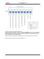
7.4
Interfaces Configuration
Part Number (Group)
Switch
Switch Name
Function
SW7 (Interfaces)
1
UART0
Enables use of UART0 (default = ON)
2
UART4
Enables use of UART4 (default = OFF)
3
HOST-SPI
Enables use of the Host SPI interface
(default = OFF)
4
SD CARD
Enables use of the SD Card interface
(default = OFF)
5
EXT. PHY (ETH)
Enables use of the external Ethernet
PHY (default = OFF)
6
TRACE
7
I2S0
8
QUAD SPI
Enables use of the JTAG itrace interface
(default = OFF)
Enables use of the I2S sound interface
(default = OFF)
Enables use of the Quad SPI flash
memory (default = OFF)
The software supplied with the board is configured to run with this setup and the corresponding
pin multiplexing configuration.
Before activating an interface – please configure the MB86R12 to use the corresponding
pin multiplex group when booting. This is achieved using the U-Boot bootstrap utility,
described further on in this User Manual.
Please check also board schematics page 2 and the corresponding page of the interface.
SW7 can be found on page 2 of the schematic (Rev1.7).
FSEUGCC-UM_SK86R12-01-Rev1.4
- 20 -
© Fujitsu Semiconductor Europe GmbH
Emerald-P Promotion Board
SK-86R12-01
All these interfaces are deactivated by default.
Before activating an interface – please configure the MB86R12 to use the corresponding
pin multiplex group when booting. This is achieved using the U-Boot bootstrap utility,
described further on in this User Manual.
Please check also board schematics page 2 and the corresponding page of the interface.
SW6 can be found on page 2 of the schematic (Rev1.7).
FSEUGCC-UM_SK86R12-01-Rev1.4
- 21 -
© Fujitsu Semiconductor Europe GmbH
Emerald-P Promotion Board
SK-86R12-01
8 Interfaces
8.1
Display Outputs
8.1.1 Display Outputs HDMI (2 available)
The SK-86R12-01 incorporates two HDMI outputs:
•
•
Display 0 (this is the top connector of the stack!)
Display 1
These Emerald-P outputs are connected to TFP410PAP (Texas Instruments) DVI transmitters
(U2, U3) and use the RGB888 output format. The DVI transmitters are configured to operate
without any additional software programming.
Their basic configuration is:
•
•
•
•
•
•
Single clock
High Voltage Swing
24 Bit
Single Edge Mode
Rising Edge Mode
De-skewing: 0 ns
If you need to change this configuration, this can be done using switches S1 (for Display 0) and
S3 (for Display 3).
S1 can be found on page 9 of the schematic (Rev1.7).
FSEUGCC-UM_SK86R12-01-Rev1.4
- 22 -
© Fujitsu Semiconductor Europe GmbH
Emerald-P Promotion Board
SK-86R12-01
Part Number (Group)
S1 (uses U2)
S3 (uses U3)
Switch
Switch Name
1
CTL1
2
CTL2
3
CTL3
Function
When DKEN = OFF, CTL[3:1] configure
the DK de-skew inputs of the
TFP410PAP device (U2/U3) in order to
adjust the setup and hold times of the
pixel data inputs relative to the clock
input.
CTL1 (default = ON = 0)
CTL2 (default = ON = 0)
CTL3 (default = OFF = 1)
The default setting, CTL[3:1] = '100'
(recommended setting, TCD=±0ns).
4
DKEN
Data de-skew enable (default = OFF,
logical '1', i.e. enable de-skew)
Notes
•
•
HDMI output 0 (Display 0) can only be used in conjunction with
PinMuxGroup #D / MuxMode #0.
HDMI output 1 (Display 1) can only be used in conjunction with
PinMuxGroup #F / MuxMode #1
S3 can be found on page 10 of the schematic (Rev1.7).
For details on de-skewing, please refer to the datasheet of the TFP410PAP (Texas Instruments)
device.
FSEUGCC-UM_SK86R12-01-Rev1.4
- 23 -
© Fujitsu Semiconductor Europe GmbH
Emerald-P Promotion Board
SK-86R12-01
8.1.2 Display Outputs via Pin Headers (also for Glyn TFT family displays)
The SK-86R12-01 board also routes the RGB888 outputs of the three display units of MB86R12
'Emerald-P' to 1.27mm pitch pin headers.
The X2 connector on the board was designed especially for the use of displays from Glyn's EDT
display family. These TFT displays can be ordered via www.glyn.de or also via Fujitsu
Semiconductor Support and offer on-board touchscreens and a fixed connector layout for a
wide set of different resolutions and sizes.
The CAP2VI_7 pin on the board can be used to enable the panel by software and the SPI0_DO
pin can be used to dim the panel using PWM (Pulse Width Modulation), see schematics page
11 for both pins.
Before using a pin header – please configure the MB86R12 to use the corresponding pin
multiplex group when booting. This is achieved using the U-Boot bootstrap utility,
described further on in this User Manual.
Required Pin Multiplexing Modes
Display0 requires PinMuxGroup #D / PinMuxMode0
Display1 requires PinMuxGroup #F / PinMuxMode1
Display2 requires PinMuxGroup #I / PinMuxMode3
FSEUGCC-UM_SK86R12-01-Rev1.4
- 24 -
© Fujitsu Semiconductor Europe GmbH
Emerald-P Promotion Board
SK-86R12-01
8.1.3 Display Output via APIX™ TX (3GBit)
The MB86R12 'Emerald-P' chip provides three APIX TX interfaces which can be independently
configured via software. The interfaces are downwards compatible to APIX1 (1GBit).
All the APIX interfaces are ESD protected and provided with Rosenberger connectors.
The Display 0 output (APIX TX0) can also utilize the 'Power over APIX' (PoA) functionality,
which means that it is optionally possible to provide 12V (the Vinput of the board) over the APIX
line. This is not used by default. Please note that additional components need to be assembled
for PoA operation (refer to the schematics).
For details refer to board schematics page 12 and page 13.
8.2
Video Capture Interfaces
8.2.1 Capture via APIX RX (RGB888) 3GBit Link
This mode enables the capture of data via the APIX Link (3GBit) via an internal APIX RX path.
Please refer to page 13 of the board schematics
8.2.2 Capturing via HDMI (RGB888)
To enable the capture of video data in high quality via the HDMI interface, enable switch 5
(Enable_HDMI_Capture) of SW6. The data is converted into the RGB888 format and
transferred to the Capture0 interface of MB86R12 'Emerald-P'.
Required Pin Multiplexing Mode
PinMuxGroup #I, MuxMode #0 is required.
To additionally enable the capture of sound data transmitted via the HDMI interface, enable
switch 6 (Enable_HDMI_Capture_Sound) of SW6. The data is then transferred to the I2S0
interface of MB86R12 'Emerald-P'.
Please refer here to page 31 of the board schematics and the AD9398 datasheet for details
(see appendix).
AD9398 I2C Write address: 0x98
AD9398 I2C Read address: 0x99
8.2.3 Capturing Video via Pin Header X34 (RGB888)
MB86R12 'Emerald-P's Capture0 interface can be accessed via pin header X34, in order to feed
a 24 bit RGB888 data stream into the device.
Required Pin Multiplexing Mode
PinMuxGroup #I, MuxMode #0 is required.
Please also refer to page 31 of the board schematics.
FSEUGCC-UM_SK86R12-01-Rev1.4
- 25 -
© Fujitsu Semiconductor Europe GmbH
Emerald-P Promotion Board
SK-86R12-01
8.2.4 Capturing Video (ITU656)
MB86R12 'Emerald-P' has four ITU656 video capture units. From a board design point of view
(connecting components used), these are organized as two pairs:
•
•
Capture 0 and Capture 3
Capture 1 and Capture 2
8.2.4.1 Capture Interface 0 and 3
The following table shows the connectors used on the board.
Capture Interface
Connectors Used
S-Video
Cinch
0
X24
X25
3
X26
X28
Decoder
TVP5150AM1
2
Capture 0: I C (8 bit) Write address: 0xBA
2
Capture 3: I C (8 bit) Write address: 0xB8
Required Switch Settings
SW6: switch 1 = ENABLE_CAPTURE_0 = ON
SW6: switch 4 = ENABLE_CAPTURE_3 = ON
8.2.4.2 Capture Interface 1 and 2
The following table shows the connectors used on the board.
Capture Interface
Connectors Used
S-Video
Cinch
1
X32
X31
2
X30
X29
Decoder
SAA7113H
2
Capture 1: I C (8 bit) Write address: 0x4A
2
Capture 2: I C (8 bit) Write address: 0x48
Required Switch Settings
SW6: switch 2 = ENABLE_CAPTURE_1 = ON
SW6: switch 3 = ENABLE_CAPTURE_2 = ON
Required Pin Multiplexing Mode (for all Video Capture units)
PinMuxGroups #H+I, MuxMode #0 is required.
The TVP5150AM1 and SAA7113H decoders must be programmed correctly via I2C (e.g. to
select the input signal S-Video or CVBS*).
* The board is supplied for use with S-Video signals. For CVBS input, board must be modified (components
removed). Please contact Fujitsu support for details and consult Texas Instruments Application Report 'TVP5150AM1
Anti-Aliasing Filters' (document SLEA087A, 2010).
Please check the datasheet of the respective device for details.
Please refer to page 29 of the board schematics for details.
8.2.5 Video Capture for 360° Wrap Around View (using all 4 capture units)
If you have purchased the SK86R12-01 'Emerald-P' Promotion Board as a part of the 360°
Wrap Around View package, then you will be using all four video capture units simultaneously
(whether 4x ITU656 or 4x digital input). This package includes an additional add-on board ('Addon 360° Wrap Around View board') which has an X33 connector, with the inputs for all four
capture units, as well as SPI0 , UART0, GPIOs and I2C pins to control the connected cameras.
Please refer to Chapter 8 for details on the 360° WAV product.
FSEUGCC-UM_SK86R12-01-Rev1.4
- 26 -
© Fujitsu Semiconductor Europe GmbH
Emerald-P Promotion Board
SK-86R12-01
8.3
Ethernet (using internal MAC, external PHY)
The SK86R12-01 Promotion Board has an RJ45 connector (X17) which is used to connect the
board to an Ethernet network (this will typically be a small local network on your workplace,
used for development work).
By default, the board operates in a 100MBit mode, although the MB86R12 has a built-in 1GB
MAC. However, the board itself can not support the faster link because the copper track routing
on the PCB also has to take the multiplexed use of the Ethernet pins into account, and this
makes full speed usage impossible.
To use the Ethernet functionality, please set switch 5 of SW7 to ON (Enable_ext_PHY).
Required Pin Multiplexing Mode
PinMuxGroup #I, MuxMode #1 or 2 are required to use the internal MAC and PHY units for
Ethernet communication.
Please refer to page 18 of the board schematics for details.
Important Note (Ethernet Interface not available in WAV Configuration)
Please note that due to the pin multiplexing configuration that is required to use the hardware in
360° Wrap Around View mode, the Ethernet Interface is not available! Consider using a USBNetwork adapter as an alternative.
8.4
USB Host Interface
The SK86R12-01 Promotion Board has a USB connector (X23) that can be used to connect
external hardware (USB mouse, USB keyboard, USB hub, USB stick etc.).
The USB interface can always be used and is independent of any pin multiplexing settings.
Please refer to page 20 of the board schematics for details
8.5
JTAG / 16 Bit Trace Interface
The SK86R12-01 Promotion Board incorporates a JTAG / 16 Bit Trace debugging interface to
enable fast and easy access to the register set of MB86R12 'Emerald-P'.
To use this interface, connect the 38 pin MICTOR connector of your debugger to connector J2
on the PCB.
Note that Fujitsu's GDC Support Team can also deliver an adapter for standard 20 pin 2.54mm
pitch connectors (e.g. for Realview). Contact your Fujitsu sales representative if you require
such an adapter.
Required Pin Multiplexing Mode
The JTAG interface is enabled by default and a specific pin multiplexing setup is not required for
use.
PinMuxGroup #B, MuxMode #3 is required to use the 16 Bit Trace interface.
Switch 6 of SW7 must be set to ON for use of the Trace interface (Enable_Trace).
Please refer to page 22 of the board schematics for details
FSEUGCC-UM_SK86R12-01-Rev1.4
- 27 -
© Fujitsu Semiconductor Europe GmbH
Emerald-P Promotion Board
SK-86R12-01
Mini-USB to RS232 / HOST SPI / I2C Interface
8.6
The SK86R12-01 Promotion Board has a bus-powered FTDI chip that provides the following
interfaces via virtual COM ports:
•
•
•
two RS232 ports
one I2C interface
one HOST SPI port
When connected via USB, Windows automatically recognizes* the FTDI hardware as follows:
•
•
•
•
'USB Serial Converter A': can be used as the HOST SPI interface
'USB Serial Converter B': can be used as an I2C interface direct to devices (see below)
'USB Serial Converter C': can be used as the UART0 interface
'USB Serial Converter D': can be used as the UART4 interface
* If you are using Windows XP, you will need to install the FTDI drivers manually first (see Quick Start chapter).
8.6.1 HOST SPI Interface
The HOST SPI interface can be used to access the MB86R12 'Emerald-P' device. Fujitsu GDC
Studio, is a complete development tool suite that includes a driver for this purpose. Check this
link for details on Fujitsu Developer Suite:
http://www.fujitsu.com/emea/services/microelectronics/gdc/swtools/fj-developer-suite.html
Required Pin Multiplexing Mode
PinMuxGroup #B, MuxMode #1 is required to use the HOST SPI interface.
Switch 3 of SW7 must be set to ON to use the HOST SPI interface (Enable_SPI_Host).
8.6.2 RS232 (UART) Ports
The RS232 ports are connected to Emerald-P's UART0 and UART4 and will be detected if a
mini-USB cable is used to connect J1 (mini-USB) to a PC.
To enable the use of the UART ports (e.g. for a terminal connection) the following settings must
be made on the board:
Switch 1 of SW7 must be set to ON (default) for UART0 (Enable_UART0) (default setting)
Switch 2 of SW7 must be set to ON (default) for UART4 (Enable_UART4)
To use a RS232 communication port, please make sure your terminal software (e.g. Tera Term
- http://ttssh2.sourceforge.jp) is configured with the following settings:
•
•
•
•
•
Baud rate:
Data:
Stop bit:
Parity:
Flow Control:
115.200 bps
8 bits
1 bit
none
none
FSEUGCC-UM_SK86R12-01-Rev1.4
- 28 -
© Fujitsu Semiconductor Europe GmbH
Emerald-P Promotion Board
SK-86R12-01
8.6.3 I2C Interface
It is possible to use this I2C interface (available on connector X10) to directly program I2C
devices on the board, although this is normally handled by the MB86R12 'Emerald-P' device.
If you wish to use this interface for test or debugging purposes, you must first obtain Third Party
software from Future Technology Devices International Ltd. (FTDI) .
Please visit the FTDI webpage for more information. http://www.ftdichip.com/ and refer to
Application Note AN_177 'User Guide For libMPSSE – I2C'.
Furthermore, you will need to modify the PCB (add 0Ω resistors at R268 and R269) and disable
the I2C unit of MB86R12 'Emerald-P'.
Please refer to page 23 of the board schematics for details
8.7
CAN Interface
The SK86R12-01 Promotion Board incorporates a CAN bus connector (X16).
If you own or have access to the Jade-L Starterkit (SK-86R03), then you can use the adapter
supplied with this to connect a 9-pin sub-D connector (10-pin pin header to 9-pin sub-D
adapter).
Please refer to page 24 of the board schematics for details.
8.8
MediaLB Interface
The SK86R12-01 Promotion Board incorporates an SMSC MOST module bus connector (X12).
This connector can be used directly with SMSC PHY+ Modules, available for different speeds
(MOST 25, 50).
For more information please check the SMSC website:
http://www.smsc-ais.com/AIS/content/view/852/818/
The MediaLB interface is also available on a seperate connector (X14).
Required Pin Multiplexing Mode
PinMuxGroup #G, MuxMode #0 is required to use the MediaLB interface.
Please refer to page 24 of the board schematics for details.
8.9
SD Card Interface
The SK86R12-01 Promotion Board provides a SD Card interface with a card reader (X16).
Switch 4 of SW7 must be set to ON to use this interface (ENABLE_SD_CARD).
Required Pin Multiplexing Mode
PinMuxGroup #F, MuxMode #0 is required to use the SD Card interface.
Please refer to page 25 of the board schematics for details.
FSEUGCC-UM_SK86R12-01-Rev1.4
- 29 -
© Fujitsu Semiconductor Europe GmbH
Emerald-P Promotion Board
SK-86R12-01
8.10 Sound
An external sound codec (WM8976) is integrated on the SK86R12-01 Promotion Board and
connects to the I2S0 interface of the MB86R12 'Emerald-P'. The codec can be programmed via
I2C. Please check the device's datasheet for details (see Appendix).
Required Pin Multiplexing Mode
PinMuxGroup #F, MuxMode #0 or #4 is required to use the sound interface.
Connector X7 has LINE_INPUT and LINE_OUTPUT jackplug connections (both are stereo).
Set switch 7 of SW7 to ON in order to use the sound interface (ENABLE_I2S0_SOUND).
Please refer to page 26 on the board schematics for details.
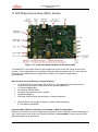
8.11 AIC / IPC (to Atlas)
The SK86R12-01 Promotion Board was also designed for deveopment work with Fujitsu's
MB9DF126 'Atlas' MCU device. For details, follow this link:
http://mcu.emea.fujitsu.com/mcu_product/detail/MB9DF126PMC.htm
The AIC/IPC (Automotive Inter Connect / Inter Process Connect) interface of the SK86R12-01
Promotion Board is identical to that of the Atlas Starterkits, but it can be used also with other
MCUs.
The diagram below shows the pinning of connector X9 (AIC/IPC).
Short pin description:
•
•
•
•
•
•
•
•
AICxx_TDxx : serial bus, transmit direction
AICxx_RDxx : serial bus, receive direction
AICxx_CLK : serial bus, clock
GPIO_to_Interruptxx : Atlas can use GPIOs to trigger interrupts on Emerald
Emerald_GPIO_xx: two GPIOs from Emerald that can be used outside
SPI0_xxxxx : SPI0 interface from Atlas
SPI1_xxxxx : SPI1 interface from Atlas
Power_Control_Emerald: soft start for Emerald board (also see section 4),
HIGH starts up the board
FSEUGCC-UM_SK86R12-01-Rev1.4
- 30 -
© Fujitsu Semiconductor Europe GmbH
Emerald-P Promotion Board
SK-86R12-01
Required Pin Multiplexing Mode
PinMuxGroup #F, MuxMode #2 is required to use the AIC/IPC interface.
Please refer to page 27 of the board schematics for details.
FSEUGCC-UM_SK86R12-01-Rev1.4
- 31 -
© Fujitsu Semiconductor Europe GmbH
Emerald-P Promotion Board
SK-86R12-01
9 Power Supply
The SK86R12-01 Promotion Board requires an external power adapter to supply an input
voltage in the range of 9V ... 18VDC. The current consumption of the board in operation is
approximately 1.5A.
The board generates various supply voltages (1V2, 1V5, 1V8, 3V3, 5V), required to power the
MB86R12 and interface devices on the baseboard. The power supplies are designed to deliver
a current of up to 4A each. A seperate 5V supply (max. 4A) is available for external use, e.g. for
external cameras, the '360° WAV add-on board' (for digital cameras), etc.
The external power input is fused and protected against reverse polarity.
9.1
External Startup
It is possible to start up the SK86R12-01 Promotion Board using an external control (e.g.
coming from an Atlas Starterkit). Pin 25 of connector X9 provides this functionality, whereby a
HIGH signal level triggers a power up sequence on the SK86R12-01 Promotion Board.
Please check page 27 of the board schematic.
FSEUGCC-UM_SK86R12-01-Rev1.4
- 32 -
© Fujitsu Semiconductor Europe GmbH
Emerald-P Promotion Board
SK-86R12-01
10 Memory
10.1 DDR3 (U27, U28)
The SK86R12-01 Promotion Board incorporates two Micron MT41J128M16HA-15E DDR3
memory devices, each with 2GBit ( = 256 MByte). These devices can attain data rates up to
1,333 MT/s (Million Transfers per second) and are organized as 16Mbit x 16 x 8 banks.
The correct configuration of the memory devices is handled by the U-Boot utility.
Please refer to page 16 of the board schematics for details.
10.2 QUAD SPI Flash (U40)
The SK86R12-01 Promotion Board incorporates a QUAD SPI flash device from Spansion
(S25FL129P0XNF100) which offers a capacity of 128MBit (16 Mbyte). It is also possible to boot
the system from this flash (provided the following setup exists).
Switch 8 of SW7 must be set ON to use the SPI flash (ENABLE_QUAD_SPI_FLASH).
Required Pin Multiplexing Mode
PinMuxGroup #A, MuxMode #1 is required to use the QUAD SPI flash.
Please refer to the specification of the memory device for programming details.
Please refer to page 17 of the board schematics for details.
10.3 NAND Flash (U39)
The SK86R12-01 Promotion Board incorporates a 2GBit NAND Flash device (with 1-Bit ECC)
from Micron (MT29F2G16ABAEAWP-IT) which offers 16 bit data lines. In the default setup (the
device is not used as a boot device), the memory is selected via Chip Select signal XCS1
(default) over 0Ω resistor R344. However, if you wish to boot from the NAND, you must
assemble R340 (also a 0Ω resistor) and use Chip Select signal XCS0 (the MB86R12 always
boots from XCS0).
Please refer to the datasheet of this device for details on programming.
Please refer to page 17 of the board schematics for details.
10.4 NOR Flash (U34, U35)
The Emerald-P Promotion Board incorporates two 1GBit NOR flash devices from Micron (type:
JS28F00AM29EWL).
Use Chip Select XCS0 to access the NOR flash chip. Normally, the memory will be accessed in
either 16 bit or 32 bit mode (the bus is designed to handle both modes) but it is also possible to
address the two devices separately in 16 bit mode, making it possible to reserve one device for
data that is not touched (a safe backup system) while the other device is being reprogrammed
and used. In the event of problems, this would ensure that it is always possible to boot from the
backup device.
FSEUGCC-UM_SK86R12-01-Rev1.4
- 33 -
© Fujitsu Semiconductor Europe GmbH
Emerald-P Promotion Board
SK-86R12-01
10.4.1 Overview of possible Use Configurations
16 bit access (U34 active)
•
•
Set SW5 to switch position 2 – 3 (default)
Set SW8 to switch position 2 – 3 (default)
The first NOR device (U34) only will be used in 16 bit mode. U35 is then not used and could be
used for system recovery if booting from U34 fails.
16 bit access (U35 active)
•
•
Set SW5 to switch position 2 – 3 (default)
Set SW8 to switch position 1 – 2
The second NOR device (U35) only will be used in 16 bit mode.
32 bit access (U34 + U35 active)
•
•
Set SW5 to switch position 1 – 2
Set SW8 to switch position 2 – 3
Both devices will be activated using the XCS0 signal.
FSEUGCC-UM_SK86R12-01-Rev1.4
- 34 -
© Fujitsu Semiconductor Europe GmbH
Emerald-P Promotion Board
SK-86R12-01
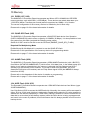
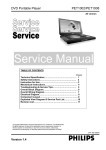
11 360°Wrap Around View (WAV) System
Figure 11-1: Fully assembled SK-86R12-01 Board for WAV
The SK86R12-01 Promotion Board is also supplied as a part of the 360° Wrap Around View
product. In this configuration, the (modified) board is supplied together with four video capture
cameras and its default switch configuration is different (to match the application's
requirements).
WAV Current Scope of Delivery (analog cameras)
•
•
•
•
•
•
•
1x Emerald-P Promotion Board (SK-86R12-01), with additional cinch connectors to
connect the board to the output ports of the camera adapter box
1x Camera Adapter Box
4x Cameras (ND-BC100II)
All cables required to set up the system
Calibration Markers
DVD and USB stick with documentation, software and tools
Optional Extra (not included in delivery, please order seperately):
8" LCD Monitor (800x600)
Important Note (Ethernet Interface not available in WAV Configuration)
Please note that due to the pin multiplexing configuration that is required to use the hardware in
360° Wrap Around View mode, the Ethernet Interface is not available! Consider using a USBNetwork adapter as an alternative.
FSEUGCC-UM_SK86R12-01-Rev1.4
- 35 -
© Fujitsu Semiconductor Europe GmbH
Emerald-P Promotion Board
SK-86R12-01
U-Boot Modifications Required for WAV use
(Please check these settings if you install a Linux BSP update from the Fujitsu website!)
•
•
•
•
•
pinmux=80000000
pinmux2=00000168
tcon_pinctrl=93
cpumem=mem=256M
gpumem=gpumem=256M
SK86R12-01 Promotion Board Layout Modifications
Please note that the SK-86R12-01 board is supplied in a slightly modified form, when delivered
as a part of the 360° Wrap Around View product package. The differences are:
•
•
ADC filter configuration
Additional cinch connectors are mounted:
o X25 [capture 0]
o X31 [capture 1]
o X29 [capture 2]
o X28 [capture 3]
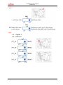
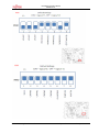
SK86R12-01 Promotion Board Switch Configuration
Please note that this setup requires an additional add-on board (SK-86R12-WAV01).
FSEUGCC-UM_SK86R12-01-Rev1.4
- 36 -
© Fujitsu Semiconductor Europe GmbH
Emerald-P Promotion Board
SK-86R12-01
FSEUGCC-UM_SK86R12-01-Rev1.4
- 37 -
© Fujitsu Semiconductor Europe GmbH
Emerald-P Promotion Board
SK-86R12-01
FSEUGCC-UM_SK86R12-01-Rev1.4
- 38 -
© Fujitsu Semiconductor Europe GmbH
Emerald-P Promotion Board
SK-86R12-01
FSEUGCC-UM_SK86R12-01-Rev1.4
- 39 -
© Fujitsu Semiconductor Europe GmbH
Emerald-P Promotion Board
SK-86R12-01
Connectors Used
•
•
•
•
Display Out 0 (upper HDMI Connector)
MiniUSB for UART0
CAN Adapter cable, connected to X16
Camera Connectors X25, X28, X29, X31 (Cinch Connectors)
FSEUGCC-UM_SK86R12-01-Rev1.4
- 40 -
© Fujitsu Semiconductor Europe GmbH
Emerald-P Promotion Board
SK-86R12-01
12 Appendix
12.1 Literature and References Used
−
Emerald-P Promotion Board Schematics:
http://www.fujitsu.com/downloads/MICRO/fme/displaycontrollers/sch-sk-86r12-01rev1-5.pdf
−
Datasheet SAA7113H Video Processor:
http://www.nxp.com/pip/SAA7113H.html
−
Datasheet Wolfson WM8976 Sound Codec:
http://www.wolfsonmicro.com/products/codecs/WM8976/
−
Datasheet TFP410PAP DVI Transmitter:
http://www.ti.com/lit/ds/symlink/tfp410.pdf
−
Datasheet External PHY DP83865DVH:
http://www.national.com/pf/DP/DP83865.html
−
Datasheet Spansion QUAD SPI Flash S25FL129P0XNF100:
http://www.spansion.com
−
Datasheet NAND Flash Micron MT29F2G16AADWP-ET:
http://download.micron.com/pdf/datasheets/flash/nand/2gb_nand_m29b.pdf
−
Fujitsu Developer Studio – a great tool for register access:
http://www.fujitsu.com/emea/services/microelectronics/gdc/swtools/fj-developersuite.html
−
Datasheet FTDI FT4232HL Chip :
http://www.ftdichip.com/Support/Documents/DataSheets/ICs/DS_FT4232H.pdf
−
SMSC PHY+ Modules:
http://www.smsc-ais.com/AIS/content/view/852/818/
−
Datasheet Video Processor TVP5150AM:
http://www.ti.com/product/tvp5150
FSEUGCC-UM_SK86R12-01-Rev1.4
- 41 -
© Fujitsu Semiconductor Europe GmbH
Emerald-P Promotion Board
SK-86R12-01
12.2 Figures
Figure 3-1: System Overview ................................................................................................................ 10
Figure 4-1: Console output.................................................................................................................... 12
Figure 4-2: Running Demo .................................................................................................................... 12
Figure 6-1: Standard Board Layout/Assembly ...................................................................................... 14
Figure 11-1: Fully assembled SK-86R12-01 Board for WAV................................................................ 35
FSEUGCC-UM_SK86R12-01-Rev1.4
- 42 -
© Fujitsu Semiconductor Europe GmbH