1
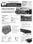
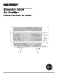
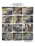
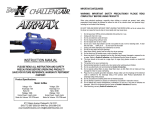
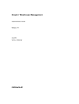
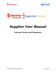
Cleaning Water Naturally™
CONTENTS
OWNER’S MANUAL FOR:
SW20 & SW40
Aeration
Pond Series Shallow Water
Aeration Systems
SECTION
System Components
1
Safety2
Seasonal Operation
3
System Installation
4
Maintenance5
Troubleshooting6
Replacement Parts
7
Warranty8
THANK YOU FOR CHOOSING
The Airmax® Aeration System
Air
You have purchased the most efficient and cost-effective
aeration system available on the market today!
1. System Components
Airmax® Composite Cabinet
2
1. Enhanced cooling system tunnels air flow evenly
through the cabinet with a high flow cooling fan &
high density air intake pre-filter.
2. Composite cabinet with removable top protects
components while providing easy access
1
3. Elevated base protects against damaging flood
water
3
4. Pre-wired electrical box simplifies electrical
connections for easy setup
4
Cabinet Size: 23”L x 17”W x 15”H
SilentAir™ LR Series Linear Diaphragm Compressor
1. High efficiency, linear diaphragm compressor
1
2
2. Air Filter maximizes the life of the compressor
6. Airline quick disconnects for easy
system removal and storage
3. Rubber compressor mounts reduce noise and
vibration for silent operation
5
6
5. Heat-resistant, 3⁄8” flex-tube protects
against high temperatures of the
compressor
4
3
4. Airflow manifold simplifies airflow management to
individual diffusers
ProAir™ 2 Weighted Diffuser
1
2
EasySet™ AIRLINE
1. PTFE non-stick membrane diffuser sticks provides
the synergy of air stones while being virtually
maintenance-free
2. Check valve prevents back pressure to
compressor
3
3. Weighted design keeps diffuser submerged while
maintaining an upright position during installation
Diffuser Size: 15”L x 9.25”W x 3.75”H
• Self-Weighted Airline: 3/8” 100’ Roll (#510118), 5/8” 100’
Roll (#510119): Lead-free weighted airline is made of durable
PVC composite. Fish hook resistant and kink-free. Use from
pond’s edge to diffuser.
• Direct Burial Airline (sold separately): 5/8” 100’ Roll (#510120)
Flexible, yet kink-free. Bury from cabinet and compressor to
pond’s edge when placing the cabinet and compressor away
from the pond.
* Depending on the type of
installation, additional
connector kits may be
required. See section 7 for
connector kits.
2. Safety
SAFETY
• Read all operating instructions carefully.
• To reduce the risk of electric shock, connect only to a properly grounded, grounding-type receptacle.
If in doubt, have the outlet checked by a qualified electrician.
• This unit is to be used in a circuit protected by a ground fault circuit interrupter (GFCI).
• Disconnect unit from power source before handling or maintenance.
• Repair or exchange of cable/power cord must be carried through by the supplier/manufacturer.
• This unit has not been investigated for use in swimming pool areas.
CAUTION
• Never connect to an extension cord. This may result in equipment failure.
• Do not allow anything to rest on the power cord.
• Do not place the cabinet where people may step on the power cord.
• Never override or “cheat” electrical or mechanical interlock devices.
• Never attempt any maintenance function that is not specified in the user manual.
• Never operate the system if unusual noises or odors are detected. Disconnect the power cord from
the outlet and call for service.
GROUNDING INSTRUCTIONS
This product must be grounded. In the event of an electrical short circuit, grounding reduces the risk
of electric shock by providing an escape wire for the electric current. This product is equipped with a
cord having a grounding wire with an appropriate grounding plug. The plug must be plugged into an
outlet that is properly installed and grounded in accordance with all local codes and ordinances.
WARNING – Improper installation of the grounding plug is able to result in a risk of electric shock.
When repair or replacement of the cord or plug is required, do not connect the grounding wire to either
flat blade terminal. The wire with insulation having an outer surface that is green with or without yellow
stripes is the grounding wire.
For 120 VAC products:
This product is for use on a nominal 120V circuit, and has a grounding plug similar to the plug illustrated
in sketch A in Figure below. A temporary adapter similar to the adapter illustrated in sketches B and
C may be used to connect this plug to a 2-pole receptacle as shown in sketch B when a properly
grounded outlet is not available. The temporary adapter shall be used only until a properly grounded
outlet (sketch A) is installed by a qualified electrician. The green colored rigid ear, lug, or similar part
extending from the adapter must be connected to a permanent ground such as a properly grounded
outlet box cover. Whenever the adapter is used, it must be held in place by a metal screw.
For 230 VAC products:
This product is for use on a circuit having a nominal rating more than 120 V and is factory-equipped with
a specific electric cord and plug for connection to a proper electric circuit. Only connect the product to
an outlet having the same configuration as the plug. Do not use an adapter with this product. When the
product must be reconnected for use on a different type of electric circuit, the reconnection shall be
made by qualified service personnel.
3. Seasonal Operation
The circulation of poor quality, low oxygen, deep water to the pond’s surface can introduce harmful gases
and by-products into the previously healthy upper regions of the water column. These by-products can
make the upper regions unfit for aquatic life and could result in fish-kill.
To Prevent Initial Fish-Kill:
Follow this procedure anytime system has been shut-off for an extended period of time.
Day 1: Run system for 30 minutes; turn system off for remainder of day.
Day 2: Run system for 1 hour; turn system off for remainder of day.
Day 3: Run system for 2 hours; turn system off for remainder of day.
Day 4: Run system for 4 hours; turn system off for remainder of day.
Day 5: Run system for 8 hours; turn system off for remainder of day.
Day 6: Run system for 16 hours; turn system off for remainder of day.
Day 7: Begin running system 24 hours/day, 7 days/week.
Summer Operation
To reduce the risk of fish kills in hot summer months and for optimum aeration benefits,
Airmax® Aeration Systems should run continuously throughout the summer. To enhance pond health,
reduce mucky bottoms and enhance pond’s aesthetic appeal, try Pond Logic® products:
Ma
MuckAway™
Pc
PondClear™
Nb
Nature’s Blue™
Bk
Black DyeMond™
Tw
Winter Operation
Owner assumes all responsibility for operating Airmax® Aeration System during winter months.
Operating in freezing conditions on an ice-covered pond will cause large open water areas at diffuser
sites. Ice thickness around open areas will be much thinner than the surrounding areas. Airmax®
strongly recommends that “Danger - Thin Ice” be posted at frequent intervals around pond. Diffuser
plates should be moved out of the deepest points of pond to allow a safe zone for fish dormancy and to
avoid “super cooling” effect.
If you choose to turn your system off for the winter, do the following:
• Unplug your aeration system.
• Disconnect compressor flex-tube(s) from airline(s).
• Cover airline ends with included caps to prevent debris from entering airline.
• Move cabinet and compressor inside to keep dry.
• When turning system back on in spring, airlines may contain ice.
• Use 1 cup denatured alcohol in the airline running out to each plate.
• Turn on compressor to push through line and free any ice blockage.
• Follow initial startup procedure to avoid “shock” in the pond.
WARNING: Wrap cord neatly in or under enclosure when not in use to prevent off-season damage.
Twilight Blue™
4. System Installation
6 Easy Steps!
For quick, easy and professional installations, it is suggested that the following materials be
on-site: (None of the following are included with the Airmax® Aeration System)
• Placement Rope
• Utility razor knife
• Level
• Boat/Raft/Swimsuit
• Coast Guard-approved life jacket
• Small stone or gravel
• Shovel
• Rake
• Flathead screwdriver
• Sharpie® Marker
Location
• Locate cabinet on a solid support with adequate strength for weight of unit.
• Locate cabinet away from irrigation sprinklers.
• Wear a Coast Guard-approved life jacket; follow all safety and caution guidelines.
1
1. Decide on a location for the cabinet and prep
ground. May be placed several hundred feet from
shoreline (using direct burial airline) if power is not
available at shore.
3
2
2. Option 2 Only: Excavate trench to a minimum
of 8” of depth for direct burial line. Place and backfill
all direct burial airline (one line per diffuser).
4
WARNING: All compressor cabinets must be located above the water level.
Option 2
Option 1
3. Option 2 Only: Connect direct burial airline to
EasySet ™ self-weighted airline.
Pond’s Edge
Away from
Pond’s Edge
Option 1: When power source is available at pond’s edge, simply connect one end of EasySet™
Airline to flex-hose and other end to diffuser plate.
Steps 2 & 3 below are not necessary using this option.
Option 2: When power source is not available at pond’s edge, place SilentAir™ Cabinet next to
nearest power source. Trench Direct Burial Airline (sold separately, ½” standard irrigation pipe may
be substituted) from flex-tube to pond’s edge; then connect to EasySet™ Airline and run to diffuser
plate. Each diffuser will be a separate run of airline. Each run may not exceed several hundred feet.
5
5. Connect airline to flex lines supplied with cabinet.
Open cabinet, plug compressor and cooling fan into
power control. Plug power control cord into power
outlet. Flip power switch to the ON position.
4. Connect diffuser to airline. Extend EasySet ™
self-weighted airline to proper location. Place diffuser. To ensure proper placement, use nylon rope.
Plates should be located towards the deepest part
of the pond.
6
6. Bubbles should be noticeable from all diffuser locations. When more than one diffuser is installed, adjust
valves for maximum performance. Once adjustments are
made, wait several minutes to see results at the diffuser
location(s). Deeper placement of plate(s) and longer
runs of tube will require more flow.
5. Maintenance**
Airmax® Aeration Systems are designed for low-maintenance and require minimal
scheduled maintenance. Cabinet inlets and outlets should be kept free of debris and weed
growth allowing normal ventilation.
• Always unplug system before performing any maintenance or troubleshooting.
• Always unplug system and refer servicing to a qualified electrician when: cord is
damaged or frayed, compressor, power control, compressor fan, or other electrical
components are producing unusual noises or odors.
• Always use parts that are supplied or approved by Airmax®, Inc. Use of other parts may
result in poor performance and could create a hazardous situation.
**Local environmental conditions may require more frequent maintenance.
WARNING: Compressors are equipped with a thermal overload switch. If temperature
becomes high enough to trip the overload, the compressor will shut down. It will then
automatically start up when temperature decreases as long as power is applied.
EVERY 3-6 MONTHS - Air Filter: Clean/replace air filter. Cooling Fan: Check to ensure cooling fan is operating. Hot air
should be pulled from cabinet, not cool air blowing in.
Pressure Gauge: Mark pressure gauge upon initial start up. Check to verify pressure has not significantly risen above or
dropped below initial reading. Normal operation will range between 5-10 psi.
Pressure Relief Valve: Check to ensure air is not escaping from valve. If unit is shut off, pressure will need to be released from
the system in order for compressor to restart.
EVERY 12 MONTHS - Membrane Sticks: Purge membrane sticks. For SW20 & SW40, while compressor is running, shut off
all air flow valves except one, forcing all air to one diffuser plate for 10 seconds. Repeat for each plate.
EVERY 12-24 MONTHS - Maintenance Kit: It is recommended to install a maintenance kit every 18-24 months to ensure
optimum performance.
6. Troubleshooting
IF COMPRESSOR IS NOT OPERATING:
ISSUE
CHECK
LIKELY CAUSE
Option 1: GFCI circuit tripped.
Damage to electrical cord or low voltage from power supply.
Option 2: GFCI circuit not tripped.
GFCI malfunction.
Option 1: Check compressor capacitor wiring for frays or poor connections.
Wiring loosened or was damaged during shipment or
maintenance.
Option 2: No capacitor wiring issues can
be seen.
Bad capacitor.
Option 3: Capacitor has been replaced.
Compressor is bad.
Cabinet fan is not running.
Cabinet fan is running.
CORRECTION
Contact Airmax® or local dealer for electrical
troubleshooting assistance.
Contact Airmax® or local dealer for repair/replacement.
IF COMPRESSOR IS OPERATING:
ISSUE
No bubbles at any diffusers.
No bubbles at some diffuser plates.
Large rolling bubbles instead of fine bubbles
at surface above one or more diffuser plates.
Air coming out of pressure relief valve.
Compressor stops working for periods of
time, then restarts.
Compressor shakes erratically and is making
loud noises.
CHECK
LIKELY CAUSE
CORRECTION
Option 1: No air leaks are audible in cabinet.
Compressor running louder and
possible excessive vibration.
Compressor air filter is dirty/clogged.
Clean or replace air filter. NEVER re-install wet filter.
Option 2: Compressor operating normally or
making unusual noises. Exhibits
reduced pressure and/or air flow.
Compressor needs diaphragm maintenance kit and
possibly new air filter.
Contact Airmax® or local dealer with specifications for maintenance
kit. Clean or replace air filter. NEVER re-install wet filter.
Option 1: Check for leaks at all connections
in line and in cabinet. If none are
audible, carefully spray SMALL
amount of soapy water onto connections and look for bubbles.
Vibration loosened connection or cracked fitting.
Tighten loose connection or replace cracked fitting as necessary.
Option 2: Are all flow control valves in
compressor wide open?
Improper “balancing” of diffusers.
Adjust air flow valves on manifold in cabinet until all diffusers
operate properly. See Section 4. System Installation for
more information.
Option 3: Valves in cabinet are properly
“balanced” and no leaks
are evident.
Compressor beginning to lose compression and needs
diaphragm maintenance kit.
Contact Airmax® or local dealer with compressor specifications for
maintenance kit.
Inspect each diffuser plate for malfunction.
Diffuser membrane damaged, diffuser plate fitting broken or
diffuser plate is flipped over.
Contact Airmax® or local dealer for repair/replacement.
Option 1: High pressure reading on gauge.
Inspect diffuser plates and tubing
for clogging.
Diffuser maintenance needed.
Remove any overgrowth around diffuser membrane surface. See Section 5. Maintenance for more information.
Option 2: Low pressure reading on gauge.
Diffuser plates not clogged.
Bad pressure relief valve.
Contact Airmax® or local dealer for repair/replacement.
Inspect cooling fan for proper function.
Compressor over-heating due to bad cooling fan.
Contact Airmax® or local dealer for fan replacement. If possible, leave
top of cabinet open for cooling. Otherwise, unplug system until fan
is replaced.
Option 1: Check for low voltage while
compressor is running.
Gauge of supply wires to circuit possibly undersized or
cabinet is plugged into extension cord.
If gauge of circuit wiring is incorrect, have electrician replace. NEVER
use extension cord to operate system for continual use.
Option 2: Check for clogged air filter.
Air filter in need of replacement.
Clean or replace air filter. NEVER re-install wet filter.
7. Replacement Parts
2
1
9
8
4
3
7
6
5
Cabinet & Compressor Replacement Parts
1. High Efficiency Compressor
• #120912 – SilentAir™ LR25 Linear Diaphragm Compressor
• #120913 – SilentAir™ LR50 Linear Diaphragm Compressor
• #510147 – SilentAir™ LR25 Diaphragm Maintenance Kit
• #510148 – SilentAir™ LR50 Diaphragm Maintenance Kit
3. #510302 – Cooling Fan for 115V Systems
2. Airflow Manifold Assembly
#600177 – SW20 Airflow Manifold Assembly
#600178 – SW40 Airflow Manifold Assembly
6. Air Filter
4. #510395 – Air Intake Pre-Filter
5. #490194 – 3⁄8” Flex-Tube Asembly
• #510150 – Air Filter, Complete
• #510151 – Air Filter Media Only
ProAir™ 4 Replacement Parts
7. #490333 – Diffuser Sled
8. #490340 – Check Valve
9. #510168 – PTFE 6” Membrane Stick
*#490158 – Marine Stainless Hose Clamp
*#490118 – ½” to ¾” Insert Reducer Adapter
*#490118 – 3⁄8” to ¾” Insert Reducer Adapter
*Not shown in Diagram
EasySet™ Airline
#510118 – 3⁄8” Weighted Airline, 100’ Roll
#510119 – 5⁄8” Weighted Airline, 100’ Roll
#510120 – 5⁄8” Direct Burial Airline, 100’ Roll
Connector Kits
3/8” Connector Kit
#490204
3/8” to 5/8” Connector Kit
#490205
5/8” Connector Kit
#490206
8. Warranty
Airmax®, Inc. warrants to the original purchaser (the end user) of any Airmax® Aeration System
manufactured by Airmax ®, Inc. that any aeration system component which proves to be
defective in materials or workmanship, as determined by the factory within the timeframe
specified below from the shipping date, will be repaired or replaced at no charge with a new or
remanufactured part, and returned freight prepaid. The end user shall assume all the
responsibility and expense for removal, packaging, and freight to ship to Airmax®, Inc.
to determine the warranty claim and for all reinstallation expenses.
• Cabinet – Lifetime
• Compressor – 2 Years
• Airline & Diffusers – 5 Years
The warranty is void in cases where damage results from: improper installation, improper
electrical connection, improper voltage, alteration, lightning, careless handling, misuse, abuse,
disassembly of motor or failure to follow maintenance or operating instructions. Modification or
repair by an unauthorized repair facility will void the warranty. Compressor seals, diaphragms, air
filters and diffuser membranes are considered wear parts and are not covered under warranty.
There is a metallic sticker on the side of the compressor
and the electrical box similar to what you see on the right.
For your records, copy the appropriate number below. Have
this information ready when making inquiries regarding your
Airmax® Aeration System.
__ __ __ __ __ __ __ __
WARRANTY VOID IF REMOVED
########
AIRMAX®, INC.
WWW.AIRMAXECO.COM
PURCHASE DATE:
Date unit was purchased. (Example: June 1, 2014)
N
GUARANTEED
SA
FACTIO
TIS
044_13
FAC
TIS TI
ON
Aeration
Cleaning Water Naturally™
Airmax®, Inc.
www.airmaxeco.com
866.424.7629
SA
THANK YOU FOR CHOOSING