1
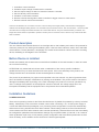
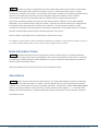
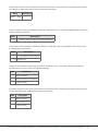
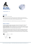
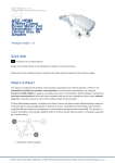
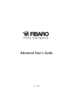
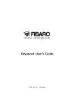
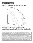
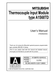
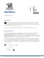
FIB_FGSS-101
Smoke detector
Firmware Version : 2.1
Quick Start
S This device is a wireless Z-Wave sensor. To include the device into the network, turn the controller into
the inclusion mode and then triple click the B-button on the casing. Further you can use the auto-inclusion
mode by setting the controller into the inclusion mode and then connect the constant current voltage supply.
Auto-inclusion only works in constant current mode.
Please refer to the chapters below for detailed information about all aspects of the products usage.
What is Z-Wave?
This device is equipped with wireless communication complying to the Z-Wave standard. Z-Wave is the
international standard for wireless communication in smart homes and buildings. It is using the
frequency of 868.42 MHz to realize a very stable and secure communication. Each message is reconfirmed
(two-way communication) and every mains powered node can act as a repeater for other nodes (meshed
network) in case the receiver is not in direct wireless range of the transmitter.
Z-Wave differentiates between Controllers and Slaves. Slaves are either sensors (S) transmitting metered or
measured data or actuators (A) capable to execute an action. Controllers are either static mains powered
controllers (C) also referred to as gateways or mobile battery operated remote controls (R). This results in a
number of possible communication patterns within a Z-Wave network that are partly or completely supported
by a specific device.
(c) 2012 Z-Wave Europe GmbH, Goldbachstr. 13, 09337 Hohenstein-Ernstthal, Germany, All rights reserved, www.zwaveeurope.com - pp 1
1.
2.
3.
4.
5.
6.
7.
Controllers control actuators
Actuators report change of status back to controller
Sensors report change of status of measured values to controller
Sensors directly control actuators
Actuators control other actuators
Remote controls send signals to static controllers to trigger scenes or other actions
Remote controls control other actuators.
There are two different role a controller can have. There is always one single primary controller that is managing the
network and including/excluding devices. The controller may have other functions - like control buttons - as well. All other
controllers don't manage the network itself but can control other devices. They are called secondary controllers. The
image also shows that its not possible to operate a sensor just from a remote control. Sensors only communicate with
static controllers.
Product description
The new Z-Wave based Smoke Sensor is an ultra light device, that is battery and 12/24 V DC powered for
maximum protection from flaming and smoldering fires. It has two alarm indicators: built-in siren and RGB
visual indicator. The 65 (diameter) x 28 (height) mm Smoke Sensor features a built-in electronic recording
device, facilitating an investigation of fire accidents.
Before Device is installed
Please read carefully the enclosed user manual before installation of the radio-actuator, in order to ensure
an error-free functioning.
ATTENTION: only authorized technicians under consideration of the country-specific installation
guidelines/norms may do works with 230?Volt mains power. Prior to the assembly of the product, the
voltage network has to be switched off and ensured against re-switching.
The product is permitted only for proper use as specified in the user manual. Any kind of guarantee claim
has to be forfeited if changes, modifications or painting are undertaken. The product must be checked for
damages immediately after unpacking. In the case of damages, the product must not be operated in any
case. If a danger-free operation of the equipment cannot be assured, the voltage supply has to be
interrupted immediately and the equipment has to be protected from unintended operation.
Installation Guidelines
POWERING MODES
There are two powering modes for the Fibaro Smoke Sensor. By default it's powered by a factory included
battery. Alternatively it can work with a constant current, after connecting a 12 / 24 VDC power supply to
+12/24 and GND terminals (see diagram no.3). Powering mode configuration is carried out automatically,
while sensor is being included into the Z-Wave network. When battery powered, a Fibaro Smoke Sensor
communicates with the Z-Wave network main controller periodically. Detected alarms are sent immediately,
but configuration parameters and associations settings only at specified wake up intervals, or at a manual
wake up (B-button triple click). In DC powering mode, configuration and associations parameters are sent
when necessary, and in addition sensor serves as a Z-Wave signal repeater.
(c) 2012 Z-Wave Europe GmbH, Goldbachstr. 13, 09337 Hohenstein-Ernstthal, Germany, All rights reserved, www.zwaveeurope.com - pp 2
(c) 2012 Z-Wave Europe GmbH, Goldbachstr. 13, 09337 Hohenstein-Ernstthal, Germany, All rights reserved, www.zwaveeurope.com - pp 3
(c) 2012 Z-Wave Europe GmbH, Goldbachstr. 13, 09337 Hohenstein-Ernstthal, Germany, All rights reserved, www.zwaveeurope.com - pp 4
(c) 2012 Z-Wave Europe GmbH, Goldbachstr. 13, 09337 Hohenstein-Ernstthal, Germany, All rights reserved, www.zwaveeurope.com - pp 5
Switching to a constant current powering mode:
1.
2.
3.
4.
Exclude a sensor from the Z-Wave network.
Disconnect the battery.
Install the constant power connecting terminal, observing the diagram 2.
Connect a constant current power source (12 / 24 VDC) to +12 and GND terminals observing wiring
diagram 1.
5. Include Fibaro Smoke Sensor into the Z-Wave network.
Installation:
1. Include the device into the Z-Wave network (see p.I). Note the inclusion process may be performed
ONLY in direct range of the main controller.
2. If the sensor is to be VDC powered, drill holes in sensor's holder. Note the sensor may be connected
to a wired alarm system controller or fire prevention system.
3. Install the sensor's holder in desired location.
4. If the sensor is to be VDC powered, connect wires observing diagram 3.
5. If the sensor is to be connected to an alarm system or fire prevention system, connect it observing to
diagram 4.
(c) 2012 Z-Wave Europe GmbH, Goldbachstr. 13, 09337 Hohenstein-Ernstthal, Germany, All rights reserved, www.zwaveeurope.com - pp 6
I
On factory default the device does not belong to any Z-Wave network. The device needs
to join an existing wireless network to communicate with the devices of this network. This process is called
Inclusion. Devices can also leave a network. This process is called Exclusion. Both processes are initiated
by the primary controller of the Z-Wave network. This controller will be turned into exclusion respective
inclusion mode. Please refer to your primary controllers manual on how to turn your controller into inclusion
or exclusion mode. Only if the primary controller is in inclusion or exclusion mode, this device can join or
leave the network. Leaving the network - i.e. being excluded - sets the device back to factory default.
If the device already belongs to a network, follow the exclusion process before including it in your network.
Otherwise inclusion of this device will fail. If the controller being included was a primary controller, it has to
be reset first.
To include the device into the network, turn the controller into the inclusion mode and then triple click the Bbutton. Further you can use the auto-inclusion mode by setting the controller into the inclusion mode and
then connect the constant current voltage supply. Auto-inclusion only works in constant current mode.
Operating the device
SMOKE DETECTION
Fibaro Smoke Sensor responds to physical presence of smoke. Smoke presence is required for the device
to react. Fibaro Smoke Sensor performs a self test each 5 seconds and checks for smoke presence. Having
detected smoke presence, the sensor checks 3 more times, at 1 second interval, whether the smoke is
actually present. Once the smoke presence is confirmed, Fibaro Smoke Sensor triggers an alarm.
Smoke alarm is signaled by sending an appropriate alarm frame to devices and the Z-Wave controller,
opening NC contact, and also by a constant sound signal and LED diode blinking red. Once the smoke
alarm has ceased, the sensor checks 3 times, at 1 second interval, whether the smoke has actually
disappeared before getting back to normal operation, i.e. performing a self test each 5 seconds and
checking for smoke presence.
There are 3 sensitivity levels of the optical smoke detector used in Fibaro Smoke Sensor. By default, the
detector is set to the middle sensitivity level. Sensitivity level depends on the parameter 82 settings.
DETECTING FIRE THROUGH TEMPERATURE ALARM
Apart from detecting smoke presence, Fibaro Smoke Sensor can detect fire by recording a rapid
temperature rise. Temperature alarm threshold is user defined (parameter 81). Temperature alarm is
signaled by the LED signaling diode blinking red and an intermittent sound signal.
Wakeup Intervals - how to communicate with the device?
(c) 2012 Z-Wave Europe GmbH, Goldbachstr. 13, 09337 Hohenstein-Ernstthal, Germany, All rights reserved, www.zwaveeurope.com - pp 7
W
This device is battery operated and turned into deep sleep state most of the time to save battery
life time. Communication with the device is limited. In order to communicate with the device, a static
controller C is needed in the network. This controller will maintain a mailbox for the battery operated devices
and store commands that can not be received during deep sleep state. Without such a controller,
communication may become impossible and/or the battery life time is significantly decreased.
This device will wakeup regularly and announce the wakeup state by sending out a so called Wakeup
Notification. The controller can then empty the mailbox. Therefore, the device needs to be configured with
the desired wakeup interval and the node ID of the controller. If the device was included by a static
controller this controller will usually perform all necessary configurations. The wakeup interval is a tradeoff
between maximal battery life time and the desired responses of the device.
When in battery mode tripple click on the B-button to wake up the device.
It is possible to set the node ID to 255 to send wakeup notifications as broadcast. In this mode device takes more time to
go to sleep and drains battery faster, but can notify all it's direct neighbors about a wakeup.
Node Information Frame
NI
The Node Information Frame is the business card of a Z-Wave device. It contains information
about the device type and the technical capabilities. The inclusion and exclusion of the device is confirmed
by sending out a Node Information Frame. Beside this it may be needed for certain network operations to
send out a Node Information Frame.
Hitting the B-button three times will send out a Node Information Frame.
Associations
A
Z-Wave devices control other Z-Wave devices. The relationship between one device controlling
another device is called association. In order to control a different device, the controlling device needs to
maintain a list of devices that will receive controlling commands. These lists are called association groups
and they are always related to certain events (e.g. button pressed, sensor triggers, ...). In case the event
happens all devices stored in the respective association group will receive a common wireless command.
Association Groups:
(c) 2012 Z-Wave Europe GmbH, Goldbachstr. 13, 09337 Hohenstein-Ernstthal, Germany, All rights reserved, www.zwaveeurope.com - pp 8
1
assigned to the device status - sending the BASIC SET (default) or ALARM control frame to the
associated devices having detected fire. (max. nodes in group: 5)
2
assigned to a TMP button and the malfunction alarm. Alarm frame will be sent to the associated
devices once tampering or malfunction are detected. (max. nodes in group: 5)
3
reports the device status and allows for assigning single device only (the main controller by default the device reports its status to the main controller). (max. nodes in group: 1)
Configuration Parameters
Z-Wave products are supposed to work out of the box after inclusion, however certain configuration can
adapt the function better to user needs or unlock further enhanced features.
IMPORTANT: Controllers may only allow to configure signed values. In order to set values in the range 128
… 255 the value sent in the application shall be the desired value minus 256. For example: to set a
parameter to 200? it may be needed to set a value of 200 minus 256 = minus 56. In case of two byte value
the same logic applies: Values greater than 32768 may needed to be given as negative values too.
Smoke alarm cancellation delay (Parameter Number 1, Parameter Size 2) time period, during which the
Smoke Sensor will keep indicating the smoke alarm after smoke will have disappeared
Value
0—
17280
Description
0 - no delay, immediate cancellation 65535 - alarm cancellation inactive - Smoke Sensor will
keep indicating smoke alarm after the smoke will have disappeared. The smoke alarm can be
only ceased manually, by entering 2nd menu level (Default 0)
LED indicator and acoustic alarm turned ON / OFF at any alarm type (Parameter Number 2, Parameter
Size 1) activates/deactivates the LED indicator and acoustic alarm for any alarm type. Doesn’t affect the ZWave alarm.
Value
Description
0
acoustic and visual alarms inactive
1
acoustic alarm inactive, visual alarm active
2
acoustic alarm active, visual alarm inactive
3
acoustic and visual alarms active (Default)
(c) 2012 Z-Wave Europe GmbH, Goldbachstr. 13, 09337 Hohenstein-Ernstthal, Germany, All rights reserved, www.zwaveeurope.com - pp 9
Type of alarm frame sent to 1-st Association Group devices (smoke alarm) (Parameter
Number 5, Parameter Size 1) choose a command class used in 1-st Association Group
Value
Description
129
0 (-127) - ALARM SENSOR (SMOKE) command frame
127
255 (127) - BASIC_SET command frame (Default)
Forced dimming level sent to 1-st association group devices (Parameter Number 7, Parameter Size 1)
Forced level of dimming / opening dimmers, roller blinds etc. devices at sending turn on / open / change
level commands to 1-st Association Group’s devices.
Value
Description
1 — 99 99 means turning on the device with the last remembered status
Temperature report interval (Parameter Number 10, Parameter Size 2) Time interval between consecutive
temperature reports
Value
Description
0 — 17280 0 (Reports inactive) (Default 0)
Temperature report hysteresis (Parameter Number 12, Parameter Size 1) temperature change, resulting in
a temperature report
Value
Description
0 — 100 0 - temperature change reporting inactive (Default 20)
Alarm broadcast (Parameter Number 13, Parameter Size 1) defines the broadcast alarm setting (alarm to all
devices in direct range)
Value
Description
0
broadcast inactive (Default)
1
smoke alarm broadcast (1-st Association Group) active; tamper alarm broadcast (2-nd
Association Group) inactive
2
smoke alarm broadcast (1-st Association Group) inactive; tamper alarm broadcast (2-nd
Association Group) active
3
smoke alarm broadcast active (1-st association group); tamper alarm broadcast (2-nd
association group) active
(c) 2012 Z-Wave Europe GmbH, Goldbachstr. 13, 09337 Hohenstein-Ernstthal, Germany, All rights reserved, www.zwaveeurope.com - pp 10
Temperature measurement compensation (Parameter Number 73, Parameter Size 2) temperature value to
be added to or deducted from the current measured temperature
Value
Description
64536 — 1000
Z-Wave range test interval (Parameter Number 80, Parameter Size 1) Time period between the consecutive
Z-Wave network range tests
Value
Description
0 — 17 0 – Z-Wave network range test inactive (Default 1)
Temperature alarm threshold (Parameter Number 81, Parameter Size 1) Temperature value, above which
the temperature alarm is sent
Value
0
Description
0 – temperature alarm inactive
2 — 100 (Default 54)
Smoke Sensor sensitivity (Parameter Number 82, Parameter Size 1) There are 3 levels of sensitivity to
smoke presence. Level 1 means the highest sensitivity.
Value
Description
1
HIGH Sensitivity
2
MEDIUM Sensitivity (Default)
3
LOW Sensitivity
Black Box sensitivity level (Parameter Number 83, Parameter Size 1) Parameter specifies temperature and
smoke level after which the Black Box starts recording them
Value
Description
1
HIGH Sensitivity
2
MEDIUM Sensitivity
3
LOW Sensitivity
(c) 2012 Z-Wave Europe GmbH, Goldbachstr. 13, 09337 Hohenstein-Ernstthal, Germany, All rights reserved, www.zwaveeurope.com - pp 11
Malfunction alarm (Parameter Number 84, Parameter Size 1) Time interval in which malfuntion alarm, if
detected, is repeated using visual and acoustic alarms.
Value
Description
130 — 127
Temperature alarm (Parameter Number 85, Parameter Size 1) Time interval in which temperature alarm, if
detected, is repeated using visual and acoustic alarms.
Value
Description
130 — 127 5 means 500ms
Lack of the Z-Wave range alarm (Parameter Number 86, Parameter Size 2) Time interval in which lack of
the Z-Wave network alarm, if detected, is repeated using visual and acoustic alarms.
Value
Description
1 — 17280 360 means 30min (Default 360)
Low battery alarm (Parameter Number 87, Parameter Size 2) Time interval in which low battery alarm, if
detected, is repeated using visual and acoustic alarms.
Value
Description
1 — 17280 360 means 30min (Default 360)
temperature measurement compensation for report (Parameter Number 88, Parameter Size 1)
Consider temperature measurement compensation (parameter 73) when sending temperature report.
Value
Description
0
0 - ignore temperature compensation (Default)
1
1 - include temperature compensation
Tamper alarm (Parameter Number 89, Parameter Size 1) activates/inactivates temper switch alarm
(c) 2012 Z-Wave Europe GmbH, Goldbachstr. 13, 09337 Hohenstein-Ernstthal, Germany, All rights reserved, www.zwaveeurope.com - pp 12
Value
Description
0
0 – tamper alarm inactive
1
1 – tamper alarm active, with cancellation option available (Default)
2
2 – tamper alarm active, without cancellation option
Command Classes
Supported Command Classes
Battery (version 1)
Basic (version 1)
Wake Up (version 1)
Association (version 2)
Version (version 2)
Multilevel Sensor (version 1)
Time Parameters (version 1)
Multi Channel Association (version 2)
Configuration (version 1)
Manufacturer Proprietary (version 1)
Manufacturer Specific (version 1)
Powerlevel (version 1)
Firmware Update Meta Data (version 1)
Alarm Sensor (version 1)
Technical Data
Explorer Frame Support Yes
SDK
4.54.02
Device Type
Slave with routing capabilities
Generic Device Class
Alarm Sensor
Specific Device Class
Routing Alarm Sensor
Routing
No
FLiRS
No
Firmware Version
2.1
Explanation of Z-Wave specific terms
(c) 2012 Z-Wave Europe GmbH, Goldbachstr. 13, 09337 Hohenstein-Ernstthal, Germany, All rights reserved, www.zwaveeurope.com - pp 13
Controller — is a Z-Wave device with capabilities to manage the network. Controllers are typically
Gateways, Remote Controls or battery operated wall controllers.
Slave — is a Z-Wave device without capabilities to manage the network. Slaves can be sensors, actuators
and even remote controls.
Primary Controller — is the central organizer of the network. It must be a controller. There can be only one
primary controller in a Z-Wave network.
Inclusion — is the process of bringing new Z-Wave devices into a network.
Exclusion — is the process of removing Z-Wave devices from the network.
Association — is a control relationship between a controlling device and a controlled device.
Wakeup Notification — is a special wireless message issued by a Z-Wave device to annonces that is is
able to communicate.
Node Information Frame — is a special wireless message issued by a Z_Wave device to announce its
capabilities and functions.
Disposal Guidelines
The product does not contain hazardous chemicals.
Do not dispose of electrical appliances as unsorted municipal waste, use separate collection facilities.
Contact your local government for information regarding the collection systems available. If electrical
appliances are disposed of in landfills or dumps, hazardous substances can leak into the groundwater and
get into the food chain, damaging your health and well-being.
(c) 2012 Z-Wave Europe GmbH, Goldbachstr. 13, 09337 Hohenstein-Ernstthal, Germany, All rights reserved, www.zwaveeurope.com - pp 14