1
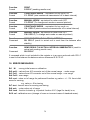
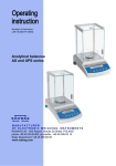
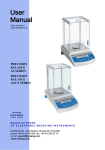
Number of instruction: LMI-16-05/03/09/ENG Analytical balances AS series MANUFACTURER OF ELECTRONIC WEIGHING INSTRUMENTS RADWAG 26 – 600 Radom, Bracka 28 Street, POLAND phone +48 48 38 48 800, phone/fax. +48 48 385 00 10 Sales Department +48 48 366 80 06 www.radwag.com MARCH 2009 2 Contents 1. TECHNICAL DATA .................................................................................6 2. BASIC INFORMATION ...........................................................................8 2.1. 2.2. 2.3. 2.4. 2.5. 2.6. Intended use ...............................................................................................8 Inappropriate use ........................................................................................8 Warranty .....................................................................................................8 Monitoring the metrological parameters of the instrument ..........................8 Data included in this user manual ...............................................................8 Staff training................................................................................................9 3. TRANSPORT AND STORAGE...............................................................9 3.1. Acceptance check.......................................................................................9 3.2. Packaging ...................................................................................................9 4. UNPACKING, INSTALLATION AND COMMISSONING .......................9 4.1. 4.2. 4.3. 4.4. 4.5. 4.6. 4.7. Installation and operation place ..................................................................9 Unpacking .................................................................................................10 Positioning ................................................................................................11 Standard accessories ...............................................................................12 Cleaning ...................................................................................................12 Connection to mains .................................................................................12 Connection of additional equipment ..........................................................12 5. BASIC FUNCTIONS OF THE INSTRUMENT ......................................12 6. KEYBOARD ..........................................................................................14 7. USER MENU .........................................................................................15 7.1. Moving in user menu ................................................................................17 7.1.1. Balance keyboard............................................................................. 17 7.1.2. Return to weighing function .............................................................. 17 8. WEIGHING ............................................................................................18 8.1. Choice of basic weighing unit ...................................................................19 8.2. Choice of weighing unit (temporary) .........................................................20 8.3. Setting accessibility of balance operating modes .....................................20 8.3.1. Choice of modes quantity accessible for user .................................. 21 8.3.2. Setting contents of P6.1 FFun – ALL parameters ............................ 22 9. MAIN SETTING PARAMETERS...........................................................23 9.1. 9.2. 9.3. 9.4. Setting level of filtering ..............................................................................24 Result confirmation ...................................................................................25 Autozero function ......................................................................................26 Light off the last display digit .....................................................................27 10. ANOTHER PARAMETERS ...................................................................28 10.1. Backlight of weighing result ......................................................................28 3 10.2. “Beep” signal – reaction on pressing key ..................................................29 10.3. Printout of all balance parameters through RS 232 port ...........................29 11. BALANCE CALIBRATION ...................................................................30 11.1. Balance with internal calibration ...............................................................30 11.2. Entering calibration menu .........................................................................32 11.3. Calibration test ..........................................................................................35 11.3.1. Balances with internal calibration ..................................................... 35 11.3.2. Balances with external calibration .................................................... 36 11.4. Manual calibration.....................................................................................37 11.4.1. Internal calibration ............................................................................ 37 11.4.2. External calibration ........................................................................... 38 11.5. Calibration report printout .........................................................................38 12. SETTING PRINTOUTS FOR GLP PROCEDURES..............................39 12.1. Setting the contents of printouts for GLP procedures ...............................40 13. BALANCE OPERATING MODES ........................................................44 13.1. Counting details of the same mass ...........................................................45 13.2. +/- control referring mass of set standard .................................................49 13.3. Control of % deviation referring mass of standard ....................................51 13.3.1. Mass of standard determined by its weighing .................................. 52 13.3.2. Mass of standard entered to balance memory by user..................... 53 13.4. Defining thickness of solids and liquids ....................................................54 13.4.1. Testing thickness solids ................................................................... 55 13.4.2. Testing thickness of liquid ................................................................ 55 13.5. Pipettes calibration ...................................................................................55 13.5.1. Data introduction .............................................................................. 55 13.5.2. Performing first series of measurements .......................................... 57 13.5.3. Performing second series of measurements .................................... 58 13.5.4. Performing third series of measurements......................................... 59 14. FUNCTIONS FOR USING RS 232........................................................61 14.1. Speed of transmission ..............................................................................61 14.2. Continuous transmission ..........................................................................62 14.2.1. Continuous transmission off in basic interval ................................... 62 14.2.2. Continuous transmission off in actual interval .................................. 63 14.3. Setting type of operating for RS 232 joint .................................................64 14.4. Designation of data type sent through RS 232 joint (only for non-verified balances) ...........................................................................................................65 14.5. Designation of minimum mass for operating of some functions ................66 14.6. Printout to printer or computer ..................................................................67 15. COOPERATION WITH PRINTER OR COMPUTER.............................68 15.1. Schedules of connecting conductors ........................................................69 15.2. Printing data with date and time................................................................70 15.3. Cooperation with statistic printout Kafka SQS ..........................................70 15.4. Format of sending data .............................................................................70 4 15.4.1. Format of sent data after pressing the PRINT button ....................... 71 15.4.2. Format of sent data for orders generated from the computer ........... 71 16. WEIGHING LOADS UNDER BALANCE ..............................................72 17. LIST OF ORDERS IN RADWAG BALANCES .....................................72 18. ERROR MESSAGES ............................................................................73 19. ADDITIONAL EQUIPMENT ..................................................................74 19.1. Vibration damping table ............................................................................74 19.2. Rack for weighing load under balance ......................................................74 19.3. Set for defining thickness of solids and liquids..........................................74 19.4. Additional display ......................................................................................74 19.5. Computer software ...................................................................................74 5 1. TECHNICAL DATA AS series balances: AS 60/C/2 AS 60/220/C/2 AS 110/C/2 AS 160/C/2 AS 220/C/2 AS 310/C/2* Maximum capacity 60g 60/220g 110g 160g 220g 310g Minimal load 1mg 1mg 10 mg 10 mg 10 mg 10 mg Readability 0,01mg 0,01/0,1mg 0,1 mg 0,1mg 0,1mg 0,1mg Tare range -60g -220g -110 g -160 g -220 g -310 g 0,1 mg 0,15 mg 0,15 mg 0,2 mg Type Repeatability 0,02mg 0,02/0,1mg Linearity ±0,05mg ±0,05/0,2mg Pan size ± 0,3 mg Φ 70 mm Sensitivity drift Φ 85 mm 2 ppm/°C in temperature +15 ° - +35 °C Working temperature +10 ° - +45 °C Power supply 230V 50Hz AC / 11V AC Calibration Internal (automatic) Display LCD with backlight * balance not verified Type Maximum capacity AS 140/C/1/CT AS 140/C/2/CT AS 240/C/1/CT AS 240/C/2/CT AS 320/C/1/CT AS 320/C/2/CT 140g/700ct 240g/1200ct 320g/1600ct Minimal load 0,004g/0,02ct 0,004g/0,02ct 0,004g/0,02ct Readability 0,0002/0,001ct 0,0002g/0,001ct 0,0002g/0,001ct Tare range -140g/-700ct -240g/-1200ct -320g/-1600ct Repeatability 0,0002g/0,001ct Linearity ±0,0002g/0,001ct Pan size Sensitivity drift Calibration Display ±0,0004g/0,002ct Φ 85 mm 2 ppm/°C in temperature +15 ° - +35 °C Working temperature Power supply 0,0004g/0,002ct +15 ° - +30 °C 230V 50Hz AC / 11V AC internal (for C/2) or external (for C/1) LCD with backlight 6 Dimensions of balance: AS series: AS 60/C/2 AS 60/220/C/2 AS 110/C/2 AS 160/C/2 AS 220/C/2 AS 310/C/2 AS series: AS 140/C/1/CT AS 140/C/2/CT AS 240/C/1/CT AS 240/C/2/CT AS 320/C/1/CT AS 320/C/2/CT 7 2. BASIC INFORMATION 2.1. Intended use Balance you have acquired serves to determine the weighing value of a load in laboratory environment. It is intended for application as a non-automatic weighing instrument only, i.e. the material to be weighed is manually and carefully placed in the center of the weighing pan. Weighing result should be read only after stable reading has been obtained. 2.2. Inappropriate use Do not use the balance as a dynamic weighing instrument. Even if small quantities of weighed material are added or removed from the weighing pan of the instrument, the reading should be taken only after stabilization of the result. Do not place any magnetic materials on the weighing pan, as this can cause damage of the measuring system of the instrument.. Be sure to avoid impact shock and overloading the balance in excess of the prescribed maximum load rating, minus any possible tare weight that has been applied. Never use the balance in an environment endangered by an explosion. This balance has not been adjusted for operation in explosive areas. There must not be any modification made to the balance. 2.3. Warranty Warranty is not valid at the following: • • • • • • Non-observation of the guidelines in the user manual, Use of balance other than specified in this manual, Alternation to or opening of the device, Mechanical damage and damage caused by media, natural water, and tear, Inappropriate erection or electric installation, Overloading of the measuring instrument. 2.4. Monitoring the metrological parameters of the instrument Metrological features of the balance should be tested by the user within regular intervals of time, within scope of quality assurance. 2.5. Data included in this user manual Please read the user manual carefully before erecting and commissioning, even if the user has is experienced with this kind of weighing instruments. 8 2.6. Staff training This balance may only be operated and looked after by trained member of staff. 3. TRANSPORT AND STORAGE 3.1. Acceptance check Please check the packaging immediately upon delivery and the device during unpacking for any visible signs of external damage. 3.2. Packaging Please retain all parts of the original packaging in case it should be necessary to transport or return items at any time. Only the original packaging should be used for return consignments. Before dispatch, disconnect all attached cables and loose/movable parts (weighing pan, protecting shields, etc). Please place any elements of the balance in its original packing. Please protect the balance and its parts against any damage while in transport. 4. UNPACKING, INSTALLATION AND COMMISSONING 4.1. Installation and operation place * * * * * * * Balance should be stored and used in locations free of vibrations and shakes, free of wind and dust. Air temperature should not exceed range between: o o +10 C ÷ +45 C Humidity of air should not exceed 80% (not condensing). When operating the balance, room temperature should not change more than 0,5°C within one hour, The balance should be placed on a stable surface not affected by vibrations and distant from heat sources. Please take special safety measures when weighing magnetic loads, as part of this balance is a strong magnet. If there is a necessity to perform measurement of such load, please use option of under hook weighing, which removes the load from area influenced by the magnet. For installation place of under hook device, please look at the bottom casing of the balance,. Avoid static charging of items to be weighed, or weighing container. In case of static discharges may occur, please ground the device. Grounding bolt is placed At the back side of the balance’s casing. 9 4.2. Unpacking Carefully remove the balance from its packaging, remove the plastic and foil wrapping and gently. Install the weighing pan, and other elements according to below schema: The balance with Φ 70 mm pan: - open side doors of weighing chamber, - inside the chamber place lower shield of weighing chamber (1), - put anti-breeze shield (2) on the lower shield, - put centering ring (3) on the lower shield, - put the balance pan (4) inside the ring, - close side doors of weighing chamber, - turn on balance supply, - pin of power adaptor should be connected to socket in the back of balance casing. 10 The balance with Φ 85 mm pan: - open side doors of weighing chamber, inside the chamber place lower shield of weighing chamber (1), inside the chamber place anti-breeze shield (2), put centring ring on the shield (3), put the balance pan inside the ring (4), close side doors of weighing chamber, turn on balance supply, pin of power adaptor should be connected to socket in the back of balance casing. 4.3. Positioning Before switching on the balance, please level the device with two adjusting feet situated at the back of the casing. Please level the balance so that the air bubble of the level is placed centrally. 11 4.4. Standard accessories • • • • Balance. Weighing pan and protecting elements. Power adapter. User manual. 4.5. Cleaning Balance should be cleaned with damp cloth. In order to clean the weighing pan of the balance, please remove it from the weighing chamber. Cleaning of the pan when installed may cause damage of the measuring system of the balance. 4.6. Connection to mains Balance can be connected to mains only with a power adapter offered as standard accessory to the balance. Nominal power supply of the power adapter (specified on the data plate of the power adapter) should be compatible to the power from mains. Please plug the adapter the socket at the back of the balance, the display with light on and show sequence of digits – display test), after which balance will display 0.0000g. if indication is different from zero, please press ESC/TARA button. 4.7. Connection of additional equipment The balance must be disconnected from the mains before connecting or disconnecting additional equipment (printer, PC) to or from the data interface. Use only accessories and peripheral equipment recommended by the manufacturer with your balance. These have been ideally coordinated to your balance. 5. BASIC FUNCTIONS OF THE INSTRUMENT Electronic balance is appropriate for precise measurements mass in laboratory conditions with possibility of setting to zero in all measure range. Balance calibration is done by F on balance keyboard. 9 - Functions for weighing units (press Units key) select default units of weighing <StUn>, Weighing in grams, Weighing in [mg], Weighing in [ct], Weighing in units from beyond SI (only: [oz], [ozt], [dwt], [t], [mom], [gn], Access to these units is blocked from factory menu level, 12 9 Functions for calibration and weighing modes Counting pieces < PIECES>, Control +/- <HiLo>, Control of deviations % according to standard mass <Perc B>, Thickness of liquids <d_Li>or solids <d_Co>, Pipettes calibration <PiPEt>. <Perc A>, 9 Choice of criteria of stable result depending on usage conditions Turn off/on system of autozero <AUTO>, Average result of weighing <AvE>, Back light function<bl>, Beep signal <bEEP>, 9 Function for using RS 232 (Esc/TARE key + print key) - Choose speed of transmission, - Define sent data as: stable / not stable, - Continuous work, - automatic work for RS 232. Moreover balance can be used to weigh hang loads, print report of calibration, check deviation of calibration and print reports of testing thickness of liquids and solids. 13 6. KEYBOARD Switches the display off. ON/OFF key. Function key. F key. Selects the work mode. MODE key. Changes measure units. UNITS key. Sends information to external instrument (PRINT) or confirms parameter value or function (ENTER). PRINT/ENTER Key. Sets indication to zero. Esc/TARA Key. 14 7. USER MENU Menu is divided into 7 basic groups. Each group has individual name starting with capital letter P. Names of groups and their contents is shown below. P1 CAL P1.1 iCAL | [Calibration] [internal calibration] P1.2 ECAL | [external calibration] P1.3 tCAL | [temperature calibration] P1.4 ACAL | both/nonE/tenno/tinnE [automatic calibration] P1.5 CALt | 1 h ÷ 12h [time of automatic calibration] P1.6 CALr | YES/no [report from calibration] P2 GLP P2.1 USr P2.2 PrJ P2.3 Ptin P2.4 PdAt P2.5 PUSr P2.6 PPrJ P2.7 PId P2.8 PFr | | | | | | | | _ _ YES/no YES/no YES/no YES/no YES/no YES/no P3 rEAd P3.1 AuE [Main user parameters] | Stand/Slouu/FASt [filtering level] [Good Laboratory Practice ] [name of user] [name of project] [printout of measurement time] [printout of measurement date] [printout of user name] [printout of project name] [printout of factory number of balance] [printout of frames] P3.2 ConF | FASt_rEL/Fast/rEL [confirmation of result] P3.3 Auto | [autozero] P3.4 Ldi9 | ALuuAYS/neper/uu_StAb P4 Print P4.1 bAud P4.2 CntA P4.3 Cntb P4.4 P4.5 P4.6 P4.7 rEPL PStb Lo P_PC On/OFF [light off the last digit] [Data transmission – RS 232] | 2400/4800/9600/19200 [speed of transmission] | YES/no [continuous printout in basic unit] | YES/no [continuous printout in currently used unit] | YES/no [manual or automatic operating] | YES/no [result printout: stable or unstable] | 000.0000 [min mass for automatic operating] | YES/no [printout destination: printer / PC computer] 15 P5 Unit [Mass units] P5.1 StUn | g/mg/ct/oz/ozt/dwt/t/mom/G P5.2 mg | YES/no [mg - milligram] P5.3 Ct | YES/no [ct – carat] P5.4 oZ | YES/no [oz – ounce] P5.5 oZt | YES/no [ozt – troy ounce] P5.6 dwt | YES/no [dwt – pennyweight] P5.7 t | YES/no [t – tael] P5.8 nno | YES/no [mom - momme] P5.9 Gr | YES/no [gr – grain] P6 Func [basic mass unit – e.g. gram] [Functions] P6.1 FFun | ALL/PcS/HiLo/PrcA/Prcb/d_Co/d_Li [choice of balance function] P6.2 PcS | YES/no [counting pieces] P6.3 HiLo | YES/no [check weighing] P6.4 PrcA | YES/no [% deviation with reference to weighed standard mass] P6.5 Prcb | YES/no [% deviation with reference to declared standard mass] P6.6 d_Co | YES/no [density determination of solids] P6.7 d_Li | YES/no [density determination of liquids] P7 othEr [Other functions] P7.1 bL | On/Aut/OFF [display backlight] P7.2 bEEP | On/OFF [keys sound] P7.3 PrnS | [printout of balance parameters] 16 7.1. Moving in user menu User moves in menu using balance keyboard. 7.1.1.Balance keyboard Enter to main menu. F key. Choice of parameters group downwards the menu or change of value of a parameter by one value downwards. MODE key. Choice of parameters group upwards the menu or change of value of parameter by one value upwards. UNITS key. Choice of parameters group, which should be activated. After pressing the key, display will indicate first from parameters of chosen group. F key. Exit to level higher e.g. to main menu. On/Off key. Resignation from change of parameter. Esc/TARA key. Confirmation / approval introduced changes. PRINT/ENTER key. 7.1.2.Return to weighing function Introduced changes in balance memory will be saved for good after return to weighing with procedure of saving changes. Press several times Esc key until display indicates message SAvE?. 17 When display indicates question press if necessary: PRINT/ENTER – confirmation of changes or F – resignation from introduced changes. After pressing appropriate key, balance will go back to weighing. 8. WEIGHING Before weighing or if the conditions of work changes (e.g. if temperature of surrounding is higher then 0,8oC) balance should be calibrated. • It is recommended to load the balance few times by mass close to max capacity before taking measurements, • Check if not load balance shows „precise zero” if measurement is stable - order , if not press key →0/T←, • by means of Units key set measure unit : [g], [mg], [ct], and if they are accessible in factory menu [oz], [ozt], [dwt], [t], [mom], [gn], • put load on balance and read result on display , • indication can be setting to zero many times by pressing key Esc/TARE (summary of mass loads record to balance memory cannot be bigger then its max capacity). Don’t unplug the balance from power supply between following measurements. Switch the balance off by pressing ON / OFF key. If user presses key ON/OFF once again balance is ready to following measurements 18 8.1. Choice of basic weighing unit Function is used to setting the initial unit with which the balance will start after switching on. Enter to submenu P5 Unit, press several times UNITS key. Display will indicate by turns available units. After choosing basic unit press key. Chosen unit will stop pulsing. 19 Possibilities of choice: • For EC verified balances, user can choose following units: [g], [mg], [ct] • For non-verified balances, user can choose following units: [g], [ct], [mg], [oz], [ozt], [dwt], [t], [mom], [gn]. Go back to weighing mode with procedure of saving changes (see point - 7.1.2. – return to weighing). ATTENTION: Balance after switching on will start with set basic unit. 8.2. Choice of weighing unit (temporary) Function enables choice of unit with which mass on the pan will be indicated. Unit will be valid until change of unit or switching on and off the balance. Each pressing the Units key, causes change of measuring unit. Possibilities of choice: • For EC verified balances, user can choose following units: [g], [mg], [ct] • For non-verified balances, user can choose following units: [g], [ct], [mg], [oz], [ozt], [dwt], [t], [mom], [gn]. 8.3. Setting accessibility of balance operating modes In this group of parameters user declares functions which are to be accessible for user after pressing F key. Enter group P6 Func. 20 8.3.1.Choice of modes quantity accessible for user Function enables user to set if after pressing F key all operating modes will be accessible (ALL) or only one from the list chosen and used by operator, or all functions unavailable (OFF). After choosing setting press PRINT key. Balance will go back to displaying name of submenu. P6.1 FFun. If function other than ALL is chosen, procedure of returning to weighing differs from remaining ones. If e.g. function PcS is chosen (procedure according to 13.1 point), to return to weighing: 21 Press key Esc/TARA, balance will return to weighing. 8.3.2. Setting contents of P6.1 FFun – ALL parameters Function enables switching off modes not used by operator. This causes faster access to used modes. 22 OFF – inaccessible mode On – accessible mode. Return to weighing (see - 7.1.2. – return to weighing). 9. MAIN SETTING PARAMETERS User can adjust balance to external conditions (filter range) or own needs (autozero working, memory of tare value). These parameters are in group <P3 rEAd>. These functions will help user to adjust balance to external conditions in which balance operates. 23 9.1. Setting level of filtering Procedure: - using key UNITS choose value of filter which is needed 1 - filtr FASt – (fast) 2 - filtr StAnd – (standard) 3 - filtr Slouu – (slow). Return to weighing (see - 7.1.2. – return to weighing). ATTENTION: The higher filtering level the longer time of weighing. 24 9.2. Result confirmation Because of various environmental conditions it is advisable to adjust the balance by selecting method of result confirmation as: FAST_rEL, Fast or rEL. Depending on selected option, time of weighing will be shorter or longer. Fast_rEL Fast rEL - fast + release - fast - release. Return to weighing (see - 7.1.2. – return to weighing). 25 9.3. Autozero function In order to ensure precise indication of balance, „AUTOZERO” function was introduced. The application of this function is automatic control and correction of zero indication of balance. When function is active comparison of results takes place at declared time intervals e.g. every 1 s, only when the pan is unloaded and results are close to zero. If results vary by value smaller than declared AUTOZERO range e.g. one division, balance will zero automatically and stable result marker– and zero indication – will be displayed. When AUTOZERO function is on each result starts from precise zero. However there are some cases where this function can be disturbance at measurements. Such instance is very slow placing of load on the pan (e.g. load pouring) in such case correction system of zero indication can also correct indication of real mass of load. Procedure: AUTOZERO AUTOZERO OFF – autozero off On - autozero on. Return to weighing (see - 7.1.2. – return to weighing). 26 9.4. Light off the last display digit Function enables light off the last digit on the display. ALuuAYS nEuEr uu_StAb - always - never - when is stable. Return to weighing (see - 7.1.2. – return to weighing). 27 10. ANOTHER PARAMETERS User can set parameters which have influence on work with balance. These parameters are contained in P5 othEr e.g. backlight and „beep” signal. Enter to P5 Others group of submenu according to point 6.1. 10.1. Backlight of weighing result bl bl bl OFF – backlight off On – backlight on Aut – If result of weighing doesn’t change for 10 seconds, backlight will turn off automatically. Return to weighing (see - 7.1.2. – return to weighing). ATTENTION: If result of weighing doesn’t change for 10 seconds, backlight will turn off automatically. Backlight is turned on when indication on display changes. 28 10.2. “Beep” signal – reaction on pressing key bEEP bEEP OFF – signal of pressing key off On - signal of pressing key on. Return to weighing (see - 7.1.2. – return to weighing). 10.3. Printout of all balance parameters through RS 232 port After pressing F key, balance parameters will be send through RS 232 port. Return to weighing (see - 7.1.2. – return to weighing). 29 11. BALANCE CALIBRATION As the acceleration value due to gravity is not the same at every location on earth, each balance must be coordinated – in compliance with the underlying physical weighing principle – to the existing acceleration due to gravity at its place of location (only if the balance has not already been adjusted to the location in the factory). This adjustment process must be carried out for the location in the factory). This adjustment process must be carried out for the commissioning, after each change of location as well as in case of fluctuating environment temperature. It is also recommend to adjust the balance periodically during weighing operation in order to obtain exact measured values. To ensure high precision of weighing corrective factor in relation to standard mass must be noted in the balance memory periodically – it is the balance calibration. Calibration should be performed: - Before the weighing, - When long breaks are between following measure series - When temperature inside the balance changes more than: 0,8° C. Kind of calibration: Internal automatic calibration * started if temperature changes * started if the time changes Manual internal calibration * initiated from the balance keyboard Calibration made with external weight * with declared mass which cannot be modified. In verified balances only automatic internal calibration and manual internal calibration is accessible. Perform the calibration when there is no load on the pan! In case when there is load on the pan, display will indicate unload. It is comment of unloading the pan. Calibration process can be stopped if it’s necessary. Press then Esc/TARA key. 11.1. Balance with internal calibration Process of calibration can be started automatically or manually. Manual way of operation is to press three times F key. System of automatic calibration will automatically perform calibration informing user about successive stages. 30 Cycle of automatic calibration proceeds as follows: - balance software detects necessity of calibration and signalizes it by marker of Celsius degree or by black marker - from this moment time of 5 minutes is counted in which weighings can be performed - when this time elapses display indicates CAL_30 message and starts count down 30..29..28 do 0 (indicated value is the counter) - user has 30 seconds to make a decision: if calibration is to be performed, does not take any actions if one wants to finish measurements presses TARE key, after its pressing balance returns to weighing showing previous result of weighing (possibility of finishing series of measurements) in 5 minutes balance will indicate CAL_30 message again - process of calibration can be postponed frequently, but fact that long postponing of calibration can be cause of bigger error during weighing should be noticed. These errors are effect of changes of temperatures and as consequence changes of balance sensitivity. Automatic system includes 3 possibilities: - calibration with regard to changes of temperature balance is provided with precise system of controlling temperature changes, temperature of calibration is registered every time, next is started if temperature of surrounding changes 0,8oC - calibration with regard to passage of time user can declare 4 spaces of time that makes criterion for calibration, following option are accessible: calibration every 1 - 12 hours. 31 11.2. Entering calibration menu P1 CAL P1.1 P1.2 P1.3 P1.4 P1.5 P1.6 iCAL uCAL tCAL ACAL CALt CALr | | | | | | both 1h YES P1.1 iCAL – Internal calibration start of internal calibration process, process is completely automatic without interference of balance operator, if pan is loaded display will indicate message about necessity of removing the load. P1.2 ECAL – External calibration calibration with external weight, which value is saved in factory menu of balance, function unavailable in verified balances. balances with internal calibration balances with external calibration P1.3 tCAL - Test of calibration comparison of internal calibration mass with its value saved in balance memory. balances with internal calibration balances with external calibration 32 P1.4 ACAL – Automatic calibration (balances with internal calibration) determination of factor, which should decide about starting the automatic internal calibration nonE – none of factors will cause start of calibration tEmP – calibration with regard to change of temperature timE – calibration with regard to time set in P1.5 CALt both – calibration with regard to time and temperature. 33 P1.5 CALt – Time of automatic calibration (balances with internal calibration) determining the time, after which automatic calibration will start. P1.6 CALr – printout from calibration report Setting printout of report after finished calibration no – printout of report off YES – printout of report on. balances with internal calibration balances with external calibration 34 11.3. Calibration test 11.3.1. Balances with internal calibration Internal calibration mass is compared to its value in the balance memory. This process is automatic. Its result is shown on the display. Process proceeds automatically and display indicates its result (if balance is connected to computer or to printer through RS 232 joint, printout of calibration test will take place). Press ESC/TARA key to return to previous screen. Procedure: Return to weighing The changes are recorded when the balance returns to weighing mode with the recording the changes. Press the ESC many times. Following question appears on the display. Select one of the options : ENTER – record / ESC – cancel (Return to weighing 7.1.2. Return to weighing). 35 11.3.2. Balances with external calibration It consists in comparison of mass of standard with mass previously saved in balance memory during the calibration. Process proceeds automatically and display indicates its result (if balance is connected to computer or to printer through RS 232 joint, printout of calibration test will take place). Press ESC/TARA key to return to previous screen. Procedure: Return to weighing (see - 7.1.2. – return to weighing). 36 11.4. Manual calibration 11.4.1. Internal calibration 1. Press F key three times 2. The balance performs the calibration automatically. During this calibration do not load the pan. After this process the balance records results of the calibration in the memory and returns to weighing mode. 3. ATTENTION: Pressing the ESC key stops the calibration process If during the calibration load is on the pan display show order about error. The calibration process is stopped. After take load off the calibration process is finished. 37 11.4.2. External calibration The external calibration should be performed with external mass class: - E2 – for balances AS 1. Start external calibration process balances with internal calibration 2. 3. 4. 5. 6. balances with external calibration Order to load off the pan appears on the display (no load on the pan). After yesing load off the pan press the ENTER key. The balance determines mass of empty pan Put load and press the ENTER After the calibration the balance returns to submenu P1.2 uCAL Return to weighing – as in the point 5.1.2. If balance is verified user does not have the possibility to perform external calibration process. 11.5. Calibration report printout After calibration user can receive the calibration report. The report can be printed on connected printer and sent to computer or recorded in file. P1.6 CALr: P1.6 CALr: no YES – report is not printed – report is printed If the parameter has the value YES, the report is generated and sent automatically. A content of report depends on setting in submenu GLP. All options with YES attribute are printed. 38 P2 GLP P2.1 P2.2 P2.3 P2.4 P2.5 P2.6 P2.7 P2.8 uSr PrJ Ptin PdAt PuS PPrJ PId PFrn | | | | | | | | YES YES YES YES YES YES Apart from information settled in menu group the report contains: difference between calibration mass remembered by balance after last calibration and calibration mass determined during actual calibration and other information. 12. SETTING PRINTOUTS FOR GLP PROCEDURES P2 GLP is group of the parameters which declares factors on the calibration printout. P2 GLP P2.1 P2.2 P2.3 P2.4 P2.5 P2.6 P2.7 P2.8 uSr PrJ Ptin PdAt PuS PPrJ PId PFrn | | | | | | | | YES YES YES YES YES YES 39 For fields: - user (max 8 alphanumerical signs) - design (max 8 alphanumerical signs) introduce names by the balance keyboard. For the rest select: - no (do not print during report) - yes (print during report) 12.1. Setting the contents of printouts for GLP procedures P2 GLP group of parameters enabling to declare variables, which will appear on calibration printout and printout from measurement. P2 GLP P2.1 P2.2 P2.3 P2.4 P2.5 P2.6 P2.7 P2.8 USr PrJ Ptin PdAt PUSr PPrJ PId PFr | | | | | | | | YES YES YES YES YES YES 40 • P2.1 USr Option enabling to introduce name of user who operates the scale. User has possibility to introduce the name consisting of max 8 alphanumeric characters. Introduction the name is possible by the means of scale keyboard with F, MODE, UNITS and PRINT keys. 41 Available characters and their equivalents displayed by scale are shown on the drawing below: Exemplary user name introduced to scale with capital letters: OP1_WILK (operator 1 WILK) Exemplary user name introduced to scale with small letters: op1_wilk (operator 1 wilk) 42 • P2.2 PrJ Option enabling to introduce the Project name (e.g. associated with specific weighing type). Exemplary project name introduced to scale with capital letters: PRRADWAG Exemplary project name introduced to scale with small letters: prradwag • P2.3 Ptin Option enabling to print time of performed measurement. • P2.4 PdAt Option enabling to print data of performed measurement. • P2.5 PUSr Option enabling to print user name. • P2.6 PPrJ Option enabling to print project name. • P2.7 PId Option enabling to print factory number of scale. • P2.8 PFr Option enabling to print frames on printout. Parameters described above, choose the values: no YES - not to print during report - to print during report. Return to weighing (see - 7.1.2. – return to weighing). 43 13. BALANCE OPERATING MODES - Counting pieces +/- control referring mass of set standard Control of % deviation referring mass of standard Definition thickness of solids and liquids. Press MODE key: 44 After pressing MODE key , name of first available function will be indicated. Each next pressing UNITS or MODE key causes displaying name of next available functions, way of setting the functions is described in further part of this manual. 13.1. Counting details of the same mass Balance in standard execution is equipped with option of counting small pieces of the same mass. Counting pieces doesn’t operate with other balance functions. To use this option: • enter to PIECE function. • press UNITS key to start setting quantity of sample, you have at choice few options 45 • pressing UNITS key to choose of value (10, 20, 50pcs or free) • if you want to choose one them e.g. 20pcs press PRINT and proceed as shown on picture 46 If option FrEE was chosen, you must enter quantity of sample, which will serve to determine mass of single detail − − Pressing F key chooses digit which will be changed − Pressing UNITS changes value of digit • • Confirm entered value by pressing PRINT key Display will indicate LoAd message – place on the pan as many details as entered during option • Press PRINT key – balance will indicate quantity of sample (PCS symbol is active) • add remaining details, display will indicate their quantity. Return to weighing (see - 7.1.2. – return to weighing). 47 ATTENTION: If user presses F key when details are not placed on the pan, message Er8 outr will be indicated for few second and balance will automatically return to weighing. 48 13.2. +/- control referring mass of set standard Procedure of operating: Enter to function During setting threshold values following dependences take place: 49 SET LOWER THRESHOLD F – choice of set digit; Units - choice of value of digit; PRINT – confirmation of entered values SET UPPER THRESHOLD F – choice of set digit; Units - choice of value of digit; PRINT – confirmation of entered values. 50 ATTENTION: If user by mistake enters value of lower threshold higher than upper, balance will indicate error message and will return to weighing. Return to weighing (see - 7.1.2. – return to weighing). 13.3. Control of % deviation referring mass of standard Balance software enables control of deviation (in %) of weighed loads mass referring mass of standard. Mass of standard can be determined by its weighing (PERC A function) or entered to balance memory by user (PERC B function). 51 13.3.1. Mass of standard determined by its weighing Procedure: • Enter to function • • place on the pan load which mass will be accepted as standard press PRINT to confirm this operating mode • after few seconds indication 100,00% will be displayed. From this moment display will not indicate mass of weighed load but deviation of load mass placed on the pan referring mass of standard (in %). 52 13.3.2. Mass of standard entered to balance memory by user Procedure: • Enter to function. • • Display will show indication as above Using keys F – choice of set digit Units - choice of digit value set value of mass of standard, enter it to balance memory using PRINT key – display will indicate: 0,00% 53 From this moment display will not indicate mass of weighed load but deviation of load mass placed on the pan referring mass of standard (in %). Return to weighing (see - 7.1.2. – return to weighing). 13.4. Defining thickness of solids and liquids There is equipment to defining thickness of solids and liquids in additional equipment. For user request RADWAG service can render special software to determine thickness by balance accessible. 1. 2. 3. 4. 5. 6. beaker support frame of balance plunger beaker thermometer clench thermometer 54 7. 8. 9. 10. 11. 12. plunger string plunger hanger upper balance balance string down pan additional loads for levelling initial load. 13.4.1. Testing thickness solids Thickness of solids can be tested in one of 3 liquids: • • • H2O (distilled water), 0 C2H5OH (spirit 100% +/- 0.1% in temp. 20 C), AnotHEr (another liquid with known thickness) Give temperature of liquid for distilled water and spirit. For liquid with known thickness value is written on keyboard. To test thickness weigh sample on upper pan and weigh the same sample in liquid (on lower pan). Result is represented on display automatically after replacing sample in liquid. 13.4.2. Testing thickness of liquid Basic element for measuring thickness of liquid is glass plunger. It has precise capacity shown on hook. Before final measurements this value should be introduced to balance memory. To test thickness of liquid weigh glass plunger on upper pan and in tested liquid. Result of testing is shown on display automatically after introducing mass of plunger. 13.5. Pipettes calibration Process of pipettes calibration is very simple and user friendly. It amounts to introduction of environmental data, parameters of calibration process and parameters of tested pipette. 13.5.1. Data introduction To start function of pipettes calibration and to introduce necessary calibration parameters, follow the instruction from the drawing: 55 • Set n – set quantity of repetitions performed during pipettes calibration (5 ÷ 15), • Set t – set temperature for performing pipettes calibration (0,4 ÷ 25,5 °C), • Set P – set pressure of room where pipettes calibration is performed (800 ÷ 1050 hPa), • Set h – set humidity of room where pipettes calibration is performed (10 ÷ 95 %), • V0 – initial volume of pipette (introduced by laboratory assistant), • V1/2 – 50% of pipette volume (introduced by laboratory assistant), • V1 – nominal volume of pipette (introduced by laboratory assistant). 56 13.5.2. Performing first series of measurements After introduction data necessary for pipettes calibration, press ESC/TARA key (when balance displays stability mark) – balance will start first series of measurements P1 Vo. Quantity of repetitions previously declared value of Set n parameter. 57 13.5.3. Performing second series of measurements Second series of measurements is continuation of first series and procedure proceeds in the same way: 58 13.5.4. Performing third series of measurements Third series of measurements is continuation of second series (procedure does not change). When third series is completed, message will be displayed about finish of calibration (test End), after which report from pipette calibration will be sent through RS 232 to computer or printer. To finish the process of pipettes calibration, press ESC/TARA key. 59 Exemplary printout from pipettes is show on the drawing below: • Vmin, V1/2, Vmax – respectively: initial volume, 50% of pipette volume and nominal pipette volume, • Va – arithmetic mean from measurement series, • Es – value of systematic error, • Sr – value of repeatability standard deviation. 60 14. FUNCTIONS FOR USING RS 232 - Choose speed of transmission Define sent data as: stable / not stable Continuous work Setting data as additional element of parameter in printouts Turn on/off sign of last digit in printout automatic operating for RS 232. 14.1. Speed of transmission Method of setting speed of transmission: − choose required speed of transmission - 2400 bit/s - 4800 bit/s - 9600 bit/s - 19200 bit/s. Return to weighing (see - 7.1.2. – return to weighing). 61 14.2. Continuous transmission 14.2.1. Continuous transmission off in basic interval Procedure: CntA CntA no – continuous transmission off YES - continuous transmission on. Return to weighing (see - 7.1.2. – return to weighing). 62 14.2.2. Continuous transmission off in actual interval Procedure: Cntb Cntb no – continuous transmission off YES - continuous transmission on. Return to weighing (see - 7.1.2. – return to weighing). 63 14.3. Setting type of operating for RS 232 joint Procedure: rEPL no – manual operating / after pressing PRINT key rEPL YES - automatic operating / after stabilization of weighing result. Return to weighing (see - 7.1.2. – return to weighing). Automatic operating takes place according to following scheme: press TARE key to zero the balance (display will indicate marker of stable measurement and marker of zero) place the load, balance will send through the RS232 first stable measurement remove load from the pan, next measurement will be possible when weighing result +/- 50 reading units referring to zero (by next measurement zero stat is not required). 64 14.4. Designation of data type sent through RS 232 joint (only for non-verified balances) Procedure: PStb no – sending stable or temporary result of weighing PStb YES – sending stable result of weighing. Return to weighing (see - 7.1.2. – return to weighing). 65 14.5. Designation of minimum mass for operating of some functions Software enables setting operating of function automatic operating. for automatic operating result will not be sent to computer or printer until indication of mass goes below set Lo net value Procedure: Return to weighing (see - 7.1.2. – return to weighing). 66 14.6. Printout to printer or computer Procedure: P_PC P_PC no YES – printout to printer – printout to computer. Return to weighing (see - 7.1.2. – return to weighing). 67 15. COOPERATION WITH PRINTER OR COMPUTER Every pressing of key < PRINT > sends signal of current display state with measuring units to computer or printer. Balance has factory setting speed of transmission 4800 bit/s. If external mechanism (printer, computer) require digferent setting of speed of transmission, change factory setting on speed in menu (parameter bod) Transmission parameters programmed in balance: - Speed of transmission - 2400 – 19200 bit / s - Data bits -8 - Stop bit -1 - Parity control - none. Sending weighing results to computer can take place: - manually - after pressing PRINT key continuously – after function activating or sending steering commend automatically – when result is stable (if REPL YES and before placing weighed load balance indicated value below set Lo value) on demand computer – see List of messages Value indicated by display can be sent through connection in series as: - stable – start of sending the information will take place when weighing result is stable - unstable – state of display is sent to external device when pressing PRINT key, and on printout such state is marked with <?> before weighing result. 68 15.1. Schedules of connecting conductors WEIGHT 2 (RxD) 3 (TxD) 4 (DTR) 5 (GND) 6 (DSR) 7 (RTS) 8 (CTS) COMPUTER 3 (TxD) 2 (RxD) 6 (DSR) 5 (GND) 6 (DTR) 8 (CTS) 7 (RTS) 69 15.2. Printing data with date and time Every printout of weighing can be printed with date and time of measurement. It’s possible if balance is connected to printer Kafka 1/Z or Kafka SQ S. After connecting balance and printer set in balance menu parameters of P2 GLP group: PdAt on value YES Ptin on value YES 15.3. Cooperation with statistic printout Kafka SQS After connecting balance to printer KAFKA SQ S statistic of measurement is possible to do. Example of printout with statistics from series of measurement: 1 2 3 4 5 6 9:02:15 9:02:39 9:02:58 9:03:15 9:03:34 9:03:48 + + + + + + 7.0016 5.0152 12.0171 9.9937 12.0169 22.0111 g g g g g g Data 13.09.2001 Godz. 9:04 n sum x 6 68.0556 g x 11.34260 5.92328 g 52.22 5.0152 22.0111 16.9959 g average value standard deviation % factor of variancy g min value g max value g difference max – min s srel min max R batch quantity summary of mass of samples 15.4. Format of sending data Result of weighing can be sent from balance to external device after pressing the PRINT button on the balance or after sending order from the computer. Presented formats are conformable to settled parameter Pd_d = 1 (printout without last digit) for balances. 70 15.4.1. Format of sent data after pressing the PRINT button Depending on setting of P4.5 PStb parameter only stable measurement or mass of instantaneous mass will be sent. For verified balance printout of temporary measurements will be blocked for instantaneous measurements. 14 - 16 17 18 LF unit space mass 13 CR 4 - 12 mark space stability marker Format of printout 1 2 3 stability marker – [space] if stable [?] if unstable [^] if there is an error of exceeding the range on + [v] if there is an error of exceeding the range on Mark – [space] for positive values or [-] for negative values mass – 9 marks alignment to the right units – 3 marks alignment to the left 15.4.2. Format of sent data for orders generated from the computer Balance after receiving the command answers first: XX_A CR LF XX_I CR LF XX _ ^ CR LF XX _ v CR LF XX _ E CR LF – commend understood, realization started – commend understood, but unavailable at the moment – commend understood, but max range is exceeded – commend understood, but min range is exceeded – error occurred while command realization – exceeded time limit while waiting for stable result (time limit is characteristic parameter of balance) – name of command 1-3 4 5 6 7 8 - 16 17 18 - 20 21 22 Command space stability marker space mark mass space unit CR LF XX And afterwards 71 Command – 1 ÷ 3 marks stability marker – [space] if stable [?] if unstable [^] if there is an error of exceeding the range on + [v] if there is an error of exceeding the range on mark – [space] for positive values or [-] for negative values mass – 9 marks alignment to the right unit – 3 marks alignment to the left 16. WEIGHING LOADS UNDER BALANCE In standard analytical and precision balances can weigh load on suspension. To use this function: • Remove plastic plug in basic of balance • There is suspension in the basic of balance. It’s installed for good. • Install hook to hang load (hook isn’t standard equipment for balance), weigh load on hook. Attention: • Suspension cannot be turned around, move or manipulate. Mechanism of balance can be damaged this way. • Mass all additional elements as balance, string should be settled to zero by pressing key Esc/TARE. 17. LIST OF ORDERS IN RADWAG BALANCES Function Format TARA T CR LF (setting to tare) Function Format ZERO Z CR LF (setting to zero) Function Format PRINT SI CR LF (sending results when stab) 72 Function Format PRINT S CR LF (sending results now) Function Format CONSTANCE WORK - equivalent for key conA on C 1 CR LF (start continuous transmission off in basic interval) Function Format MANUAL WORK - equivalent for order conA OFF C 0 CR LF (To change work mode on manual printout) Function Format CONSTANCE WORK - equivalent for key conb on CU 1 CR LF (start continuous transmission off in actual interval) Function Format MANUAL WORK - equivalent for order conb OFF CU 0 CR LF (To change work mode on manual printout) Function Command SEND THE RESULT IN ACTUAL INTERVAL SU CR LF (result in actual unit is sent from the balance after stability) Function SEND RESULT IN ACTUAL INTERVAL IMMEDIATELY (result in actual unit sending results now) SUI CR LF Command If command which is not included in the register or is an error and ends with CR LF is sent to the balance the balance returns command E S CR LF. 18. ERROR MESSAGES Er1 Hi - wrong initial mass or calibration Er2 nuLL - values from A.D converter out of the normal range - under range Er3 FuL1 - values from A.D converter out of the normal range - over range Er4 FuL2 - over range Er5 rout - value out of range for performed function e.g value > +/- 2% from initial mass for zeroing, e.g. value <= 0 for tarring Er7 tout - timeout error for zeroing and tarring Er8 outr - enter value out of range Er9 Lock - function locked e.g. to protect function if LFt (legal for trade) is on, Er10 cal - calibration error (change of mass or incorrect mass of standard mass). 73 19. ADDITIONAL EQUIPMENT 19.1. Vibration damping table Thanks to this stable base all vibrations are eliminated.Inside of table marble plate is installed which makes foundation for balance. 19.2. Rack for weighing load under balance It is used when weighing under balance is neccesary. It is usefull for magnetic load or when thickness of products is defined. Racks are used also during tests for absorptiveness of materials e.g. absorptiveness of foamed polystyrene. Structre of rack is made of steel. Rack is 330mm high. 19.3. Set for defining thickness of solids and liquids It’s appropriate for weighing with precision 1mg. It enables to define thickness solids and liquids. This procedure is fully automatically user only puts samples on weighing pans. 19.4. Additional display Characteristics: Length of conductor between additional display and balance – 1,5m, plastic casing, possibility of bending the display. 19.5. Computer software PW-WIN 2004 – gathering data from any balance made by RADWAG. RAD-KEY 2000 – enables to introduce result of weighing to Exel. REC-FS 2000 – making mixtures. It has its own programmed contents base according to recipes are made. Number of instruction: LMI-16-05/03/09/ENG 74 MANUFACTURER OF ELECTRONIC WEIGHING INSTRUMENTS RADWAG 26-600 Radom Bracka 28 Street POLAND Central phone +48 48 38 48 800 phone/fax. + 48 48 385 00 10 Sales Department + 48 48 366 80 06 www.radwag.com 75