1
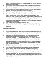
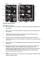
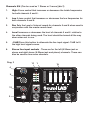
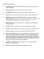
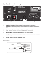
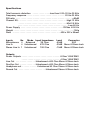
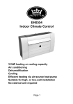
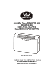
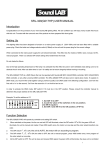
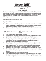
SoundLab Mixer Amplifier
G743AB
User Manual
Thank you for buying a professional Soundlab mixer amplifier. This product
incorporates the latest in mixer amplifier technology and should provide the
user with high quality trouble free sound for many years. To help you derive
the most from you Soundlab mixer amplifier please carefully read the
following user manual.
User Manual for G743AB (SCP6115M)
Important Notes
1.
This manual is part of the product and should be kept with the unit at all
times. Please read it carefully before using the product. A copy of this
manual is available on request www.electrovision.co.uk
This is a professional product and is not designed for use in a domestic
environment.
2.
!
1.
2.
3.
4.
5.
6.
7.
8.
Safety Precautions
Risk of Electric Shock
This product must be earthed at all times.
Connection to the mains should be by the mains lead supplied. Fixed
installations should only be undertaken by a qualified person.
The product and the mains lead should be checked regularly for
damage. Any repair should only be undertaken by a qualified person.
The product and the mains lead should be tested each year by a
qualified person (this is a legal requirement).
Do not expose this product to rain, moisture, extremes of temperature,
acids, alkalies or any other corrosive or reactive agents. Failure to do so
may lead to a risk of fire, electrical shock or product failure/damage.
Make sure the power supply is switched off before connecting this
product to the mains supply. All volume controls should be set at zero.
Do not attempt to open the enclosure. There are no user serviceable
parts inside. All repairs/inspections should be undertaken by a qualified
person.
Disconnect from the mains when not in use.
This amplifier can produce high sound pressure levels that can lead to
hearing damage. It is the user’s responsibility to regulate the sound
level according to the environment it is used in. In fixed installations the
9.
10.
11.
12.
13.
14.
use of a sound-limiting device is recommended. This can be viewed at
www.electrovision.co.uk.
Do not allow liquid or foreign objects to be inserted into this product.
Should this happen by accident do not attempt to repair the product.
Repairs should only be undertaken by a competent person.
Do not subject the product to heavy impacts. This can cause internal
damage that can go unnoticed by visual inspection.
This mixer amplifier is heavy. Take care when lifting. Seek advice if you
are not sure how to lift an item correctly.
The mixer amplifier should be placed on a safe, stable and level surface
that is vibration free. Always make sure the product is stable and
cannot fall when in use. When used on a mobile stand always check the
stand is capable of accepting the weight of the product. The stand
should be checked for defects before mounting the product. Never use
this product on a stand that is damaged or is not capable of accepting
the weight of the product.
This product is not suitable for domestic use.
When used in a fixed installation the product should be installed by a
qualified personal in accordance with the relevant health and safety
legislation.
Operating Precautions.
1.
2.
3.
4.
5.
6.
Do not turn the amplifier up so that the sound becomes distorted. This
will damage the speakers and could damage the internal amplifier. This
is not covered by the guarantee.
Make sure this product is switched off and all volume controls are
turned down before connection to the mains (see controls and
functions). All items
connected to the unit (CD players, electric
instruments etc.) should be switched off and volume controls turned
down before connection to the mains (see instruction books for the
appropriate product). A surge protection device is recommended for
use with this product. The amplifier should be switched on first and
then connected products.
Position the product correctly and safely before switching on. See item
13 of the safety precaution guide.
Only use high quality interconnecting leads. They will improve the
sound quality. These can be viewed at www.electrovision.co.uk
This product should only be cleaned with a damp cloth. Do not use any
cleaning agents such as detergents or solvents.
Do not use any spray cleaners or lubricants on any of the controls or
switches. Make sure the speakers are connected before switching on.
The speaker leads should be checked for damage before use. Only use
high quality speaker leads. These can be viewed at
www.electrovision.co.uk
3
Diag. 1
0
0
-15
1 REV
+15
0
2
HI
+15
7
0
REV
HI
HI
REV
0
0
REV
HI
REV
HI
REV
0
10
+15 -15
0
+15
0
CHANNEL
-20db
10 -15
LOW
-20db
CHANNEL
+15
LEVEL
CHANNEL -15
LEVEL
+15 0
-15
-20db
10
-15
10
0
-10db
REV
LOW
-15
010
0
10
-15
CHANNEL
-15
+15
LOW
1
3
MASTER
+15
CHANNEL
2
LEVEL -20db
LEVEL
+15
0
2 5/6
CHANNEL
+15
+15
0
-15
10
+15
MA
L
-20db
LEVELPHONES
4
4
0
0
10
10 0
0
10
10
0
10
0
010
0
10
PHANTOM
6
A/S 250V
X 20mm
No. F126L)
POW
HI
0
0
LOW
1 4
+15 -15
+15
0
LOW
-15
10 0
0
3
LEVEL
MIC 3
0
DELAY
3
-15
LOW
-15
Diag. 2
0
LINE 3
MIC 1
MIC 4
LINE 1
5
Controls and Functions
LINE 4
MIC 2
LINE 5 LINE 2
5
LINE 6 MIC 3
LINE 3
MIC 4 MAIN
6
Channels 1-4 (Diag. 1)
1.
Hi A tone control that increases or decreases the treble frequencies for
the channel.
2
Low A tone control that increases or decreases the low frequencies for
Complies with
Complies with
the channel
EN 60065 EN
EN 60065 EN 55103
230V~50Hz 200VA
Ta max 35ºC
230V~50Hz 20
Ta max 35ºC
3.
Rev Sets
the Level of internal reverb for the channel when used in
THIS UNIT MUST BE EARTHED
conjunction with the master reverbFORlevel.
PROFESSIONAL USE ONLY
4.
No. F126L)
Level Increases or decreases the channel level(Partrelative
to the other
SPEAKER OUTPUTS
channels being used. The level should
be turned all the way down when
2 x 100W @ 8
2 x 150W @ 4
not in use.
5.
Line 6.35mm (1.4”) high impedance input that accepts line level source
equipment.
DO NOT
T2A A/S 250V
5 X 20mm
OBSTRUCT THE
VENTILATION
6.
THIS UNIT MUST
G743AB (SCP6115M)
Mic XLR balanced line input optimised for a microphone or other low
impedance sources. Pin 2 is positive. This connector has a 15V
phantom power supply on pins 2 and 3 at all times when used with the
phantom power button (see dia 3) Warning. Because of the phantom power only
connect microphones or products with low impedance balanced line outputs. Always check the
manufacturer’s specifications before connecting.
7.
20db Press this button to attenuate the line input signal -20dB to fit the
high level signal source.
Channels 5/6 (Can be used as 1 Stereo or 2 mono) (dia 2)
1.
High A tone control that increases or decreases the treble frequencies
for both channels 5 and 6 .
2.
Low A tone control that increases or decreases the low frequencies for
both channels 5 and 6.
3.
Rev Sets the Level of internal reverb for channels 5 and 6 when used in
conjunction with the master reverb level.
4.
Level Increases or decreases the level of channels 5 and 6 relative to
the other channels being used. The level should be turned all the way
down when not in use.
5.
-10dB Press this button to attenuate the line input signal -10dB to fit
the high level signal source.
6.
Stereo line input sockets . These are for the left (6.35mm jack or
phono and right stereo (6.35mm jack and phono) channels. These can
also be used as two mono channels.
Diag. 3
4
REV
11
DELAY
1
13
Model G743AB
POWER
2 x 150w
GRAPHIC EQUALISATION
0
10
3
0
10
0
10
REV
5/6
MASTER
CHANNEL
MAIN
LEVEL
PHONES
12
0
10
0
5
0
10
POWERED MIXER
10
PHANTOM
LINE 6
MAIN OUT
10
2
REV/AUX OUT
6
7
PHONES
REC OUT
8
9
Output controls (Diag. 3)
1.
Graphic Adjusts the equalisation of the main mix before output to the
internal amplifier.
2.
Main Controls the overall volume level of the system.
3.
Rev (Master) Controls the amount of reverb in the main mix.
4.
Delay Increases or decreases the time factor of the reverb unit (6).
5.
Phantom Provides a 15V phantom power to channels 1-4 when
pressed down. Warning : Make sure all channels are turn down before turning this on or off. Do
not plug or unplug microphone after this is switched on. Do not use this if you are using any
unbalanced products connected to the 3 pin XLR. It can cause damage.
6.
Main (Out) 6.35mm (1/4”) full output for sending a source signal to
another amplifier.
7.
Rev/Aux 6.35mm output for use with external effects products.
8.
Rec Out 6.35mm TRS jack for sending a signal to a recording device.
9.
Phones Headphone out put controlled by Phones (12) knob.
10.
Output level Meter This level meter indicates the signal level being
sent to the internal amplifier. The upper red Led (when illuminated)
indicates the maximum signal level the internal amplifier can take has
been exceeded and the volume(s) should be turned down. While this
light is illuminated the sound will be audibly distorted and can lead to
damage of both the product and the speakers.
11.
On/Off Power LED When illuminated the Led indicates that the
product is receiving power.
12.
Phones Increases or decreases the headphone output.
Rear. (Diag. 4)
2
4
Complies with
EN 60065 EN 55103
230V~50Hz 200VA
Ta max 35ºC
THIS UNIT MUST BE EARTHED
FOR PROFESSIONAL USE ONLY
T2A A/S 250V
5 X 20mm
(Part No. F126L)
SPEAKER OUTPUTS
2 x 100W @ 8
2 x 150W @ 4
DO NOT
OBSTRUCT THE
VENTILATION
3
1.
1
Speaker Outputs 6.35mm output for connection to speakers.
Warning. Do not connect or disconnect the speakers while the unit is switched on. All connections
should be made before switching on the power and all volume controls should be turned all the way
down.
2.
Fuse holder Contains the fuse that protects the product.
3.
Mains Cable Connects the product to the mains supply.
Warning. Make sure all connections have been made and all volume controls have been turned down
before switching on.
4.
On/Off Switch Turns the power on or off
Connections
INPUTS
FOOTSWITCH
XLR
Line
GND
Balanced
PIN 2 +VE
PIN 1 GND
PIN 3 -VE
+VE
PIN 2 +VE
Un-Balanced
PIN 1&3 GND
Latching (Closed: Reverb Off)
Specifications
Total harmonic distortion . . . . . . . . . . . . . . .less than 0.5% 20 Hz-20 KHz
Frequency response . . . . . . . . . . . . . . . . . . . . . . . . . . . . . . . . .20 Hz-20 KHz
S/N ratio . . . . . . . . . . . . . . . . . . . . . . . . . . . . . . . . . . . . . . . . . . . . . . . .>80dB
Channel EQ . . . . . . . . . . . . . . . . . . . . . . . . . . . . . . . . . . . . . . . . .High 12 KHz
. . . . . . . . . . . . . . . . . . . . . . . . . . . . . . . . . . . . . . . . .Mid 2.5 KHz
. . . . . . . . . . . . . . . . . . . . . . . . . . . . . . . . . . . . . . . . . . .Low 80 Hz
Power Supply . . . . . . . . . . . . . . . . . . . . . . . . . . . . . . . . . . . .230Vac @ 50 Hz
Weight . . . . . . . . . . . . . . . . . . . . . . . . . . . . . . . . . . . . . . . . . . . . . . . . . . .10Kg
Dims . . . . . . . . . . . . . . . . . . . . . . . . . . . . . . . . . . . . . . . . .438 x 302 x 95mm
Inputs
Microphones
Line In
Stereo Line In
No
Mode Input Impedance
4 Balanced
3K Ohm
4 Unbalanced
47K Ohm
1 Unbalanced
10K Ohm
Level
Connector
-50dB
XLR
-30dB Mono 6.35mm Jack
-10dB Mono 6.35mm Jack
Outputs
Power Outputs . . . . . . . . . . . . . . . . . . . . . . . . . . . . . . . . .8 Ohm 100W RMS
. . . . . . . . . . . . . . . . . . . . . . . . . . . . . . . . .4 Ohm 150W RMS
Line Out . . . . . . . . . . . . . . . . .Unbalanced >600 Ohm Mono 6.35mm Jack
Rev/Aux Out . . . . . . . . . . . . . .Unbalanced >600 Ohm Mono 6.35mm Jack
Headphone out . . . . . . . . . . . . .Unbalanced 40 Ohm Stereo 6.35mm Jack
Record Out . . . . . . . . . . . . . . . . . . . . . . .Unbalanced Stereo 6.35mm Jack
Electrovision Ltd.
Lancots Lane
Sutton Oak
St Helens
Merseyside
WA9 3EX
UK
Tel. +44 (0)1744 745000
Fax +44 (001744 745001
www.electrovision.co.uk