1
PDS-700/DS-700 Series
User Manual
PDS-700/DS-700 Series New Features
1. Virtual COM Technology
2. Virtual I/O Technology
3. Web-server Technology
4. MiniOS7 & Xserver Inside
5. Programmable Solution
Your Powerful Tools
Create New Ideas
Create New Applications
Warranty
All products manufactured by ICP DAS are under warranty regarding defective materials
for a period of one year, starting from the date of delivery to the original purchaser.
Warning
ICP DAS assumes no liability for damages resulting from the use of this product. ICP
DAS reserves the right to change this manual at any time without notice. The information
furnished by ICP DAS is believed to be accurate and reliable. However, no responsibility
is assumed by ICP DAS for its use, nor for any infringements of patents or other rights of
third parties resulting from its use.
Copyright
Copyright 2008 by ICP DAS. All rights are reserved.
Trademark
The names used for identification only may be registered trademarks of their respective
companies.
PDS-700 Series User Manual ( V1.2, Oct.2008) ----- 1
Table of Contents
1.
2.
3.
INTRODUCTION ..............................................................................................................................................................6
1.1.
WHY ETHERNET SOLUTIONS? ...................................................................................................................................6
1.2.
WHY VXCOMM TECHNOLOGY? ................................................................................................................................7
1.3.
WHY WEB SERVER TECHNOLOGY? ..........................................................................................................................9
TYPICAL APPLICATIONS FOR THE PDS-700/DS-700 ...........................................................................................10
2.1.
RS-232/485/422 DEVICE NETWORKING ..................................................................................................................10
2.2.
ETHERNET I/O APPLICATIONS.................................................................................................................................11
2.3.
LINKING I-7000 SERIES MODULES TO AN ETHERNET NETWORK ..........................................................................12
2.4.
CONFIGURABLE ETHERNET DATA LOGGER............................................................................................................12
HARDWARE INFORMATION......................................................................................................................................15
3.1.
FEATURES .................................................................................................................................................................15
3.2.
SPECIFICATIONS .......................................................................................................................................................15
3.3.
PDS-700/DS-700 SELECTION GUIDE .......................................................................................................................20
3.4.
PIN ASSIGNMENTS ....................................................................................................................................................21
3.5.
PDS-700 WIRING CONNECTIONS.............................................................................................................................43
3.6.
DIMENSIONS AND MOUNTING ..................................................................................................................................45
3.7.
PDS-700/DS-700 SERIES DIAGNOSTICS ...................................................................................................................47
4.
SETTING UP THE PDS-700/DS-700 MODULE ...........................................................................................................51
5.
CONFIGURATION WITH WEB BROWSER ..............................................................................................................58
6.
7.
5.1.
CONNECTING TO THE PDS-700/DS-700 MODULE ..................................................................................................58
5.2.
NETWORK SETTINGS ................................................................................................................................................59
5.3.
IP FILTER SETTING ...................................................................................................................................................62
5.4.
COM PORT SETTINGS ..............................................................................................................................................63
5.5.
MISCELLANEOUS SETTINGS .....................................................................................................................................69
VIRTUAL I/O ...................................................................................................................................................................71
6.1.
TESTING THE VIRTUAL I/O ......................................................................................................................................71
6.2.
VIRTUAL I/O COMMANDS TEST ...............................................................................................................................75
6.3.
PROGRAMMING ON A PC CLIENT .............................................................................................................................77
VIRTUAL I/O COMMANDS ..........................................................................................................................................85
7.1.
$AA5 .........................................................................................................................................................................87
7.2.
$AA6 .........................................................................................................................................................................88
PDS-700 Series User Manual ( V1.2, Oct.2008) ----- 2
7.3.
$AAC ........................................................................................................................................................................89
7.4.
$AACN ......................................................................................................................................................................90
7.5.
$AAGCN ..................................................................................................................................................................91
7.6.
$AALS .......................................................................................................................................................................92
7.7.
$AAF.........................................................................................................................................................................93
7.8.
$AAM .......................................................................................................................................................................94
7.9.
@AA .........................................................................................................................................................................95
7.10.
@AA(DATA) .............................................................................................................................................................96
7.11.
#AAN .........................................................................................................................................................................97
7.12.
#AA00DD...................................................................................................................................................................98
7.13.
#AA1NDD ..................................................................................................................................................................99
7.14.
~** ...........................................................................................................................................................................100
7.15.
~AA0 .......................................................................................................................................................................101
7.16.
~AA1 .......................................................................................................................................................................102
7.17.
~AA2 .......................................................................................................................................................................103
7.18.
~AA3EFF .................................................................................................................................................................104
7.19.
~AA4P.....................................................................................................................................................................106
7.20.
~AA4S .....................................................................................................................................................................107
7.21.
~AA5P.....................................................................................................................................................................108
7.22.
~AA5S .....................................................................................................................................................................109
7.23.
APPLICATION NOTES ..............................................................................................................................................110
8.
CONSOLE / TELNET COMMANDS LIST ................................................................................................................113
8.1.
OPERATION FLOWCHART.......................................................................................................................................113
8.2.
REGULATE INIT/NORMAL MODE ...........................................................................................................................114
8.3.
COMPARISON SHEET (INIT/RUN/CONSOLE MODES) .............................................................................................115
8.4.
COMMAND LIST ......................................................................................................................................................116
APPENDIX A: LINKING TO A DEVELOPMENT PC.......................................................................................................138
APPENDIX B: FRAME GROUND ........................................................................................................................................141
GLOSSARY ..............................................................................................................................................................................142
1.
ETHERNET ...................................................................................................................................................................142
2.
INTERNET .....................................................................................................................................................................142
3.
TCP/IP.........................................................................................................................................................................142
4.
TCP (TRANSMISSION CONTROL PROTOCOL) ............................................................................................................142
5.
UDP (USER DATAGRAM PROTOCOL) .........................................................................................................................142
6.
GATEWAY ....................................................................................................................................................................142
7.
IP (INTERNET PROTOCOL) ADDRESS ..........................................................................................................................143
PDS-700 Series User Manual ( V1.2, Oct.2008) ----- 3
8.
MAC (MEDIA ACCESS CONTROL) ADDRESS ..............................................................................................................143
9.
SUBNET MASK .............................................................................................................................................................143
10.
ARP (ADDRESS RESOLUTION PROTOCOL) ............................................................................................................143
11.
RARP (REVERSE ADDRESS RESOLUTION PROTOCOL) ........................................................................................144
12.
ICMP (INTERNET CONTROL MESSAGES PROTOCOL) ..........................................................................................144
13.
PING ........................................................................................................................................................................144
14.
PACKET ...................................................................................................................................................................144
15.
SOCKET ...................................................................................................................................................................144
16.
CLIENTS AND SERVERS...........................................................................................................................................145
17.
FIRMWARE ..............................................................................................................................................................145
FAQ ...........................................................................................................................................................................................146
1.
HOW TO ACCESS THE REMOTE PDS-700/DS-700 THAT PLACED BEHIND AN NAT OR FIREWALL? .........................146
2.
HOW TO OPEN A VIRTUAL COM PORT THAT LARGER THAN "COM 9" BY CALLING CREATEFILE() WIN32 API? 147
3.
DOES VXCOMM DRIVER (PC) V2.00 WORK WITH VXCOMM SERVER V2.6.00? .......................................................148
4.
DOES VXCOMM DRIVER (PC) SUPPORT AUTO-RECONNECTION AFTER FIXING A NETWORK BREAK? ....................148
5.
WHY DOESN'T THE VXCOMM DRIVER (PC) RECEIVE DATA FROM THE 7188E/8000E/PDS-700/DS-700 MODULE?
149
6.
DOES THE TRANSMISSION SPEED BECOME FASTER WHEN THE SERIAL DEVICE WORKING WITH SERIAL TO
ETHERNET DEVICE SERVERS? ..............................................................................................................................................150
7.
WHY DOES THE 7188E/8000E/PDS-700/DS-700 MODULE FAIL ON A (PUBLIC) INTERNET CONNECTION? .............152
8.
CAN I USE THE SETCOMMSTATE ( ) API TO CHANGES THE BAUD RATE/DATA FORMAT SETTINGS OF A VIRTUAL
COM PORT?..........................................................................................................................................................................154
9.
HOW MANY PCS CAN BE CONNECTED TO A SINGLE 7188E/8000E/PDS-700/DS-700 DEVICE?................................154
10.
CAN I SEARCH OR CONNECT TO PDS-700/DS-700 WHEN MY PC’S IP ADDRESS IS NOT IN THE IP FILTER LIST OF
PDS-700/DS-700? HOW CAN I SOLVE IT? ...........................................................................................................................156
PDS-700 Series User Manual ( V1.2, Oct.2008) ----- 4
Packing List
The package includes the following items:
One PDS-700/DS-700 series hardware module
One printed quick start guide
One software utility CD
One download cable, CA-0910 (only for PDS-700 module)
Note:
If any of these items are missed or damaged, contact the local distributors for more
information. Save the shipping materials and cartons in case you want to ship in the future.
More Information:
Documentations
CD:\NAPDOS\PDS\PDS-700\Readme.htm
CD:\NAPDOS\PDS\PDS-700\Document\Readme.htm
VxComm Driver (Virtual COM)
CD:\NAPDOS\7188e\TCP\VxComm\driver(pc)
Firmware
CD:\NAPDOS\PDS\PDS-700\VxComm\Server(PDS)
MiniOS7
CD:\NAPDOS\PDS\PDS-700\OS_image
PDS-700 Series User Manual ( V1.2, Oct.2008) ----- 5
1. Introduction
PDS-700 is a series of Programmable Serial-to-Ethernet Device Servers while DS700 is non-programmable version. They designed to meet the most common requirements
of Internet/Ethernet applications, and enables users to remotely control your serial devices
through an Ethernet network. PDS-700 comes with a powerful and reliable Xserver
programming structure that allows you to quickly design robust Ethernet applications.
1.1. Why Ethernet Solutions?
Nowadays, the Ethernet protocol has become the de-facto standard for local area
networks. Via the Internet, connectivity is occurring everywhere, from home appliances, to
vending machines, to testing equipment, to UPS ...etc. An Ethernet network can link office
automation and industrial control networks, access remote systems and share data and
information between multivendor machines; it also provides a cost-effective solution for
industrial control networks.
PDS-700 Series User Manual ( V1.2, Oct.2008) ----- 6
1.2. Why VxComm Technology?
In general, writing a TCP/IP program is more difficult than a COM port program, or the
COM port communication system was built many years ago.
As a result, a new technology, VxComm was developed to virtualize the COM ports
of the PDS-700/DS-700 to allow up to 256 COM Ports to be used on the central
computer. The VxComm driver saves time when accessing serial devices through the
Ethernet without the need for reprogramming the COM port software on the PC.
PDS-700 Series User Manual ( V1.2, Oct.2008) ----- 7
The VxComm driver controls all the details of the Ethernet TCP/IP programming
technique; your COM port program will be able to access your serial devices through
Ethernet in the same way as through COM port with the assistance of PDS-700/DS-700
and VxComm technology.
PDS-700 Series User Manual ( V1.2, Oct.2008) ----- 8
1.3. Why Web Server Technology?
Web server technology enables configuration of the PDS-700/DS-700 via a standard
web browser interface, e.g. Internet Explorer, FireFox or Mozilla, etc. This means that it is
easy to check the configuration of the PDS-700/DS-700 via an Ethernet network without
needing to install any other software tools; thereby reducing the user’s learning carve.
PDS-700 Series User Manual ( V1.2, Oct.2008) ----- 9
2.Typical Applications for the PDS-700/DS-700
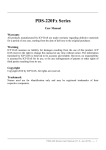
2.1. RS-232/485/422 Device Networking
--- Using Virtual COM Technology --The PDS-700/DS-700 series is designed to link RS-232/485/422 devices to an Ethernet
network. The VxComm utility allows the built-in PDS-700/DS-700 COM Port to be
virtualized to a standard COM Port of the host PC as shown below:
The original COM1/2
of the host PC
COM1/2 of the PDS700 is mapped to
COM3/4 of the host PC
COM1/2 of the PDS700 is mapped to
COM5/6 of the host PC
In the configuration above, Meter-1 is virtualized to link to COM3 of the host PC.
Therefore a program original designed for the MS-COMM standard can access the meter
without any modification.
PDS-700 Series User Manual ( V1.2, Oct.2008) ----- 10
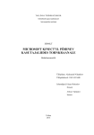
2.2. Ethernet I/O Applications
The PDS series provides 2 types of Ethernet I/O solutions:
1. Linking to I-7000 series modules
2. Built-in DIO (if the module supports the DIO function)
Linking to I-7000 series modules
The I-7000 series provides a variety of I/O operations, such as D/I, D/O, A/D, D/A,
Counter and Frequency Measurement, etc. The I-7000 series was originally designed to be
used with RS-485 networks, so COM2 on the PDS-700 can be used to link to I-7000 series
modules.
By using VxComm technology, programs that on the host PC support serial devices
can be upgraded from a RS-485 network to an Ethernet network without requiring any
modifications to the program. Refer to Sec. 2.1 for more information.
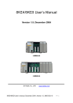
Built-in DIO
The DCON protocol is a request
/reply communication. Protocol that
is defined using a simple ASCII
format, such as $AAN, $AASi6,
#AAN, etc. and is used to access
PDS-700/DS-700 and I-7000/8000/
87k series I/O modules.
The DCON protocol command
set for the PDS-700/DS-700 is
introduced in Sec. 7. The protocol
allows access the built-in I/O through the virtual COM Ports mapped to the Port I/O of the
PDS-700/DS-700 in the VxComm Utility.
PDS-700 Series User Manual ( V1.2, Oct.2008) ----- 11
2.3. Linking I-7000 Series Modules to an Ethernet Network
The I-7000 family was originally designed for use with an RS-485 network. They are
very robust and work well under the harsh industrial environments.
The PDS-700/DS-700 enables I-7000 modules to be upgraded to an Ethernet solution.
Linking I-7000 modules to an Ethernet combines the advantages of both RS-485 and
Ethernet solutions and expands RS-485 applications to the whole world.
The VxComm approach provides an MS-COMM-compatible interface. Therefore,
previously developed programs should still function without the need for any
modifications.
2.4. Configurable Ethernet Data Logger
Using the VxComm driver, PDS-700/DS-700 + 7000 modules can be virtualized to
become COM Port + 7000 modules located on the host-PC, and then the Data Logger in
the DCON Utility can be used to access data of I-7000 from the Ethernet. Signal data
originating from the I-7000 modules can be analyzed using MS-Excel without the need to
write any custom programs
1: The DCON utility includes a log function, as show below:
PDS-700 Series User Manual ( V1.2, Oct.2008) ----- 12
2: Configure the system connection as shown below and click the “Start” button to begin
logging data.
3: Open the log file in Excel to read the log data as shown in the example below:
PDS-700 Series User Manual ( V1.2, Oct.2008) ----- 13
By using the I-7000 DCON utility and MS Excel in conjunction with the VxComm
technology, the signal data of I-7000 modules from the Ethernet network can be analyzed
without the need to write custom programs. For more information about the log function
refer to the online help feature (English and Traditional Chinese) of the DCON utility.
PDS-700 Series User Manual ( V1.2, Oct.2008) ----- 14
3. Hardware information
3.1. Features
CPU: 80186 - 80 MHz
SRAM: 512 K bytes
Flash ROM: 512 K bytes
Built-in EEPROM (16 KB)
Built-in COM Port: PDS-700: COM1 = RS-232, COM2 = RS-485
DS-712: COM1 = RS-232
DS-715: COM1 = RS-485/RS-422
Built-in Watchdog timer for harsh environments
Built-in power protection circuit
Built-in RS-485 network protection circuit for the RS-485 Port
Built-in self-tuning ASIC controller on the RS-485 Port
PDS-700: Programs download able from a PC
Built-in 5-digit LED display interface (only for display versions)
Ethernet Port: 10/100 Base-TX
Built-in OS: ICP DAS MiniOS7
ODM wanted
3.2. Specifications
System
Module Name: PDS-700/DS-700 series
CPU: 80186-80 MHz
SRAM: 512 K bytes
FLASH ROM: 512 K bytes, erase unit is one sector (64 K bytes); 100,000 erase/write
cycles.
COM Ports: PDS-700: COM1 = RS-232, COM2 = RS-485
DS-712: COM1 = RS-232
DS-715: COM1 = RS-485/RS-422
PDS-700: Programs download via COM1
PDS-700 Series User Manual ( V1.2, Oct.2008) ----- 15
EEPROM
16 K bytes
Data Retention: 40 years
1,000,000 erase/write cycles
Flash Memory
512 K bytes
Erase unit is one sector (64 K bytes)
100,000 erase/write cycles
PDS-700: COM1
RS-232: TXD, RXD, RTS, CTS, GND; Non-isolation
Communication Speed: 115200 bps max.
Program download port
PDS-700: COM2
RS-485: Data+, Data-, self-tuner internal ASIC; Non-isolation
Communication Speed: 115200 bps max.
DS-712: COM1
RS-232: TXD, RXD, RTS, CTS, GND; Non-isolation
Communication Speed: 115200 bps max.
DS-715: COM1
RS-422(TXD+, TXD-, RXD+, RXD-)/RS-485(D2+,D2-), Isolation
Communication Speed: 115200 bps max.
Display
7-segment LED: 5-digit (for display versions)
Ethernet
10/100 Base-TX
Auto-negotiating, auto MDI/MDIX, LED indicator
Power
Power Requirements: 10 ~ 30 V DC (non-regulated) (for PDS-700)
12 ~ 48 V DC (non-regulated) (for DS-700/PDS-742-IP67/
PDS-782-25)
Power Consumption: 2.0 W for the PDS-700/DS-700 series
2.7 W for the PDS-700D series
DI/O:
D/I: 3.5 V ~ 30 V max.
D/O: 100 mA, 30 V max.
PDS-700 Series User Manual ( V1.2, Oct.2008) ----- 16
PDS-700 Front View
DI/DO Channels
Wiring
information
LED Indicator
Robust
insulated and
fire retardant case
RJ-45 Jack for
10/100M Ethernet
Removable Terminal
Block for easy wiring
Serial Ports
DIN-Rail
for easy mounting
7-Segment LED
Wiring information
COM2: RS-485
COM1: RS-232
PDS-700 Series User Manual ( V1.2, Oct.2008) ----- 17
PDS-700 Rear ViewP
Robust, insulated and
fire retardant case
RoHS Compliance
(for PCB/device)
Frame Ground
DIN-Rail Mounting
CE Certification
(for PCB/device)
Initial Mode Switch
Frame Ground
DIN-Rail Lock
PDS-700 Series User Manual ( V1.2, Oct.2008) ----- 18
DS-700 Front View
COM1: RS-232
Serial Ports
LED Indicator
Robust
insulated and
fire retardant case
RJ-45 Jack for
10/100M Ethernet
Wiring
information
DIN-Rail
for easy mounting
Wiring information
COM1: RS-422/485
Serial Ports
LED Indicator
Robust
insulated and
fire retardant case
RJ-45 Jack for
10/100M Ethernet
DIN-Rail
for easy mounting
Wiring information
PDS-700 Series User Manual ( V1.2, Oct.2008) ----- 19
3.3. PDS-700/DS-700 Selection Guide
Model
DI/DO COM1 COM2 COM3 COM4 COM5 COM6 COM7 COM8
5-wire
DS-712
RS-232
2-wire
RS-485
DS-715
4-wire
RS-422
5-wire 2-wire
PDS-720
RS-232 RS-485
PDS-720D
5-wire 2-wire
PDS-721
6/7
RS-232 RS-485
PDS-721D
5-wire 2-wire 5-wire
PDS-732
4/4
RS-232 RS-485 RS-232
PDS-732D
5-wire 2-wire 4-wire
PDS-734
4/4
RS-232 RS-485 RS-422
PDS-734D
5-wire 2-wire 5-wire 9-wire
PDS-742
RS-232 RS-485 RS-232 RS-232
PDS-742D
5-wire 2-wire 5-wire 5-wire
PDS-742-IP67
RS-232 RS-485 RS-232 RS-232
5-wire 2-wire 3-wire 3-wire
PDS-743
4/4
RS-232 RS-485 RS-232 RS-232
PDS-743D
5-wire 2-wire 5-wire 5-wire 5-wire
PDS-752
RS-232 RS-485 RS-232 RS-232 RS-232
PDS-552D
5-wire 2-wire 2-wire 2-wire 2-wire
PDS-755
RS-232 RS-485 RS-485 RS-485 RS-485
PDS-755D
5-wire 2-wire 3-wire 3-wire 3-wire 3-wire
PDS-762
1/2
RS-232 RS-485 RS-232 RS-232 RS-232 RS-232
PDS-762D
RS-232 2-wire 2-wire 2-wire 2-wire 2-wire 2-wire
PDS-775-A
/RS-485 RS-485 RS-485 RS-485 RS-485 RS-485 RS-485
PDS-775D-A
5-wire 2-wire 3-wire 3-wire 3-wire 3-wire 3-wire 3-wire
PDS-782
RS-232 RS-485 RS-232 RS-232 RS-232 RS-232 RS-232 RS-232
PDS-782D
5-wire 2-wire 3-wire 3-wire 3-wire 3-wire 3-wire 3-wire
PDS-782-25
RS-232 RS-485 RS-232 RS-232 RS-232 RS-232 RS-232 RS-232
PDS-782D-25
2-wire RS-485 : Data+, Data- with Self-Tuner inside
4-wire RS-422 : TxD+, TxD-, RxD+, RxD3-wire RS-232 : RxD, TxD, GND
5-wire RS-232 : RxD, TxD, CTS, RTS, GND
8-wire RS-232 : RxD, TxD, CTS, RTS, DSR, DTR, DCD, GND
9-wire RS-232 : RxD, TxD, CTS, RTS, DSR, DTR, DCD, RI, GND
PDS-700 Series User Manual ( V1.2, Oct.2008) ----- 20
3.4. Pin Assignments
Pin Assignments for PDS-720/720D models
Only D-version modules have a 5-digit 7-SEG LED.
PDS-700 Series User Manual ( V1.2, Oct.2008) ----- 21
Pin Name Description
1
CTS1
COM1 CTS pin (RS-232)
2
RTS1
COM1 RTS pin (RS-232)
3
RXD1 COM1 RXD pin (RS-232)
4
TXD1 COM1 TXD pin (RS-232)
5
INIT* Initialization pin (for enabling/disabling AUTOEXEC.BAT)
6
D2+
COM2 Data+ pin (RS-485)
7
D2COM2 Data- pin (RS-485)
8
VS+
V+ Pin for the power supply (+10 ~ +30 V DC unregulated)
9
GND
GND Pin for the power supply (COM1 GND)
E1: 10/100 Base-TX
PDS-700 Series User Manual ( V1.2, Oct.2008) ----- 22
PDS-721/721D Pin Assignments
Only D-version modules have a 5-digit 7-SEG LED.
PDS-700 Series User Manual ( V1.2, Oct.2008) ----- 23
Pin
Name
Description
1
CTS1
COM1 CTS pin (RS-232)
2
RTS1
COM1 RTS pin (RS-232)
3
RXD1
COM1 RXD pin (RS-232)
4
TXD1
COM1 TXD pin (RS-232)
5
INIT*
Initialization pin (for enabling/disabling AUTOEXEC.BAT)
6
D2+
COM2 Data+ pin (RS-485)
7
D2COM2 Data- pin (RS-485)
8
VS+
V+ Pin for the power supply (+10 ~ +30 V DC unregulated)
9
GND
GND Pin for the power supply (COM1 GND)
10
DO6
Digital Output channel 6, 100 mA, 30 V max.
11
DO5
Digital Output channel 5, 100 mA, 30 V max.
12
DO4
Digital Output channel 4, 100 mA, 30 V max.
13
DO3
Digital Output channel 3, 100 mA, 30 V max.
14
DO2
Digital Output channel 2, 100 mA, 30 V max.
15
DO1
Digital Output channel 1, 100 mA, 30 V max.
16
DO0
Digital Output channel 0, 100 mA, 30 V max.
17
PWR
Power Input for Digital Output
18
DI5
Digital Input channel 5, 3.5 V ~ 30 V
19
DI4
Digital Input channel 4, 3.5 V ~ 30 V
20
DI3
Digital Input channel 3, 3.5 V ~ 30 V
21
DI2
Digital Input channel 2, 3.5 V ~ 30 V
22
DI1
Digital Input channel 1, 3.5 V ~ 30 V
23
DI0
Digital Input channel 0, 3.5 V ~ 30 V
E1: 10/100 Base-TX
PDS-700 Series User Manual ( V1.2, Oct.2008) ----- 24
PDS-732/732D Pin Assignments
Only D-version modules have a 5-digit 7-SEG LED.
PDS-700 Series User Manual ( V1.2, Oct.2008) ----- 25
Pin Name
Description
1
CTS1
COM1 CTS pin (RS-232)
2
RTS1
COM1 RTS pin (RS-232)
3
RXD1
COM1 RXD pin (RS-232)
4
TXD1
COM1 TXD pin (RS-232)
5
INIT*
Initialization pin (for enabling/disabling AUTOEXEC.BAT)
6
D2+
COM2 Data+ pin (RS-485)
7
D2COM2 Data- pin (RS-485)
8
VS+
V+ pin for the power supply (+10 ~ +30 V DC unregulated)
9
GND
GND pin for the power supply (COM1 GND)
10
CTS3
COM3 CTS pin (RS-232)
11
RTS3
COM3 RTS pin (RS-232)
12
TXD3
COM3 TXD pin (RS-232)
13
RXD3
COM3 RXD pin (RS-232)
14
DI0
Digital Input channel 0, 3.5 V ~ 30 V
15
DI1
Digital Input channel 1, 3.5 V ~ 30 V
16
DI2
Digital Input channel 2, 3.5 V ~ 30 V
17
DI3
Digital Input channel 3, 3.5 V ~ 30 V
18
GND
GND pin for the Digital Output (COM3 GND)
19
PWR
Power Input for Digital Output
20
DO0
Digital Output channel 0, 100 mA, 30 V max.
21
DO1
Digital Output channel 1, 100 mA, 30 V max.
22
DO2
Digital Output channel 2, 100 mA, 30 V max.
23
DO3
Digital Output channel 3, 100 mA, 30 V max.
E1: 10/100 Base-TX
PDS-700 Series User Manual ( V1.2, Oct.2008) ----- 26
PDS-734/734D Pin Assignments
Only D-version modules have a 5-digit 7-SEG LED.
PDS-700 Series User Manual ( V1.2, Oct.2008) ----- 27
Pin Name
Description
1
CTS1
COM1 CTS pin (RS-232)
2
RTS1
COM1 RTS pin (RS-232)
3
RXD1
COM1 RXD pin (RS-232)
4
TXD1
COM1 TXD pin (RS-232)
5
INIT*
Initialization pin (for enabling/disabling AUTOEXEC.BAT)
6
D2+
COM2 Data+ pin (RS-485)
7
D2COM2 Data- pin (RS-485)
8
VS+
V+ pin for the power supply (+10 ~ +30 V DC unregulated)
9
GND
GND pin for the power supply (COM1 GND)
10
TXD3+
COM3 TXD+ pin (RS-422/RS-485)
11
TXD3COM3 TXD- pin (RS-422/RS-485)
12
RXD3+
COM3 RXD+ pin (RS-422)
13
RXD3COM3 RXD- pin (RS-422)
14
DI0
Digital Input channel 0, 3.5 V ~ 30 V
15
DI1
Digital Input channel 1, 3.5 V ~ 30 V
16
DI2
Digital Input channel 2, 3.5 V ~ 30 V
17
DI3
Digital Input channel 3, 3.5 V ~ 30 V
18
GND
GND pin for the Digital Output
19
PWR
Power Input for Digital Output
20
DO0
Digital Output channel 0, 100 mA, 30 V max.
21
DO1
Digital Output channel 1, 100 mA, 30 V max.
22
DO2
Digital Output channel 2, 100 mA, 30 V max.
23
DO3
Digital Output channel 3, 100 mA, 30 V max.
E1: 10/100 Base-TX
PDS-700 Series User Manual ( V1.2, Oct.2008) ----- 28
PDS-742/742D Pin Assignments
Only D-version modules have a 5-digit 7-SEG LED.
PDS-700 Series User Manual ( V1.2, Oct.2008) ----- 29
Pin Name
Description
1
CTS1
COM1 CTS pin (RS-232)
2
RTS1
COM1 RTS pin (RS-232)
3
RXD1
COM1 RXD pin (RS-232)
4
TXD1
COM1 TXD pin (RS-232)
5
INIT*
Initialization pin (for enabling/disabling AUTOEXEC.BAT)
6
D2+
COM2 Data+ pin (RS-485)
7
D2COM2 Data- pin (RS-485)
8
VS+
V+ pin for the power supply (+10 ~ +30 V DC unregulated)
9
GND
GND pin for the power supply (COM1 GND)
10
CTS3
COM3 CTS pin (RS-232)
11
RTS3
COM3 RTS pin (RS-232)
12
TXD3
COM3 TXD pin (RS-232)
13
RXD3
COM3 RXD pin (RS-232)
14
GND3
COM3 GND pin (RS-232)
15
GND4
COM4 GND pin (RS-232)
16
RXD4
COM4 RXD pin (RS-232)
17
TXD4
COM4 TXD pin (RS-232)
18
RTS4
COM4 RTS pin (RS-232)
19
CTS4
COM4 CTS pin (RS-232)
20
DSR4
COM4 DSR pin (RS-232)
21
DTR4
COM4 DTR pin (RS-232)
22
DCD4
COM4 DCD pin (RS-232)
23
RI4
COM4 RI pin (RS-232)
E1: 10/100 Base-TX
PDS-700 Series User Manual ( V1.2, Oct.2008) ----- 30
PDS-743/743D Pin Assignments
Only D-version modules have a 5-digit 7-SEG LED.
PDS-700 Series User Manual ( V1.2, Oct.2008) ----- 31
Pin Name
Description
1
CTS1
COM1 CTS pin (RS-232)
2
RTS1
COM1 RTS pin (RS-232)
3
RXD1
COM1 RXD pin (RS-232)
4
TXD1
COM1 TXD pin (RS-232)
5
INIT*
Initialization pin (for enabling/disabling AUTOEXEC.BAT)
6
D2+
COM2 Data+ pin (RS-485)
7
D2COM2 Data- pin (RS-485)
8
VS+
V+ pin for the power supply (+10 ~ +30 V DC unregulated)
9
GND
GND pin for the power supply (COM1 GND)
10
RXD4
COM4 RXD pin (RS-232)
11
TXD4
COM4 TXD pin (RS-232)
12
RXD3
COM3 RXD pin (RS-232)
13
TXD3
COM3 TXD pin (RS-232)
14
DI0
Digital Input channel 0, 3.5 V ~ 30 V
15
DI1
Digital Input channel 1, 3.5 V ~ 30 V
16
DI2
Digital Input channel 2, 3.5 V ~ 30 V
17
DI3
Digital Input channel 3, 3.5 V ~ 30 V
18
GND
GND pin for the Digital Output (COM3/COM4 GND)
19
PWR
Power Input for Digital Output
20
DO0
Digital Output channel 0, 100 mA, 30 V max.
21
DO1
Digital Output channel 1, 100 mA, 30 V max.
22
DO2
Digital Output channel 2, 100 mA, 30 V max.
23
DO3
Digital Output channel 3, 100 mA, 30 V max.
E1: 10/100 Base-TX
PDS-700 Series User Manual ( V1.2, Oct.2008) ----- 32
PDS-752/752D Pin Assignments
Only D-version modules have a 5-digit 7-SEG LED.
PDS-700 Series User Manual ( V1.2, Oct.2008) ----- 33
Pin
Name
1
CTS1
2
RTS1
3
RXD1
4
TXD1
5
INIT*
6
D2+
7
D28
VS+
9
GND
10
CTS3
11
RTS3
12
TXD3
13
RXD3
14
GND
15
CTS4
16
RTS4
17
TXD4
18
RXD4
19
GND
20
CTS5
21
RTS5
22
TXD5
23
RXD5
E1: 10/100 Base-TX
Description
COM1 CTS pin (RS-232)
COM1 RTS pin (RS-232)
COM1 RXD pin (RS-232)
COM1 TXD pin (RS-232)
Initialization pin (for enabling/disabling AUTOEXEC.BAT)
COM2 Data+ pin (RS-485)
COM2 Data- pin (RS-485)
V+ pin for the power supply (+10 ~ +30 V DC unregulated)
GND pin for the power supply (COM1 GND)
COM3 CTS pin (RS-232)
COM3 RTS pin (RS-232)
COM3 TXD pin (RS-232)
COM3 RXD pin (RS-232)
COM3/COM4 GND pin (RS-232)
COM4 CTS pin (RS-232)
COM4 RTS pin (RS-232)
COM4 TXD pin (RS-232)
COM4 RXD pin (RS-232)
COM4/COM5 GND pin (RS-232)
COM5 CTS pin (RS-232)
COM5 RTS pin (RS-232)
COM5 TXD pin (RS-232)
COM5 RXD pin (RS-232)
PDS-700 Series User Manual ( V1.2, Oct.2008) ----- 34
PDS-755/755D Pin Assignments
Only D-version modules have a 5-digit 7-SEG LED.
PDS-700 Series User Manual ( V1.2, Oct.2008) ----- 35
Pin
Name
1
CTS1
2
RTS1
3
RXD1
4
TXD1
5
INIT*
6
D2+
7
D28
VS+
9
GND
10
D311
D3+
12
13
14
15
16
D417
D4+
18
19
20
21
22
D523
D5+
E1: 10/100 Base-TX
Description
COM1 CTS pin (RS-232)
COM1 RTS pin (RS-232)
COM1 RXD pin (RS-232)
COM1 TXD pin (RS-232)
Initialization pin (for enabling/disabling AUTOEXEC.BAT)
COM2 Data+ pin (RS-485)
COM2 Data- pin (RS-485)
V+ pin for the power supply (+10 ~ +30 V DC unregulated)
GND pin for the power supply (COM1 GND)
COM3 Data- pin (RS-485)
COM3 Data+ pin (RS-485)
N.C.
N.C.
N.C.
N.C.
COM4 Data- pin (RS-485)
COM4 Data+ pin (RS-485)
N.C.
N.C.
N.C.
N.C.
COM5 Data- pin (RS-485)
COM5 Data+ pin (RS-485)
PDS-700 Series User Manual ( V1.2, Oct.2008) ----- 36
PDS-762/762D Pin Assignments
Only D-version modules have a 5-digit 7-SEG LED.
PDS-700 Series User Manual ( V1.2, Oct.2008) ----- 37
Pin Name
Description
1
CTS1
COM1 CTS pin (RS-232)
2
RTS1
COM1 RTS pin (RS-232)
3
RXD1
COM1 RXD pin (RS-232)
4
TXD1
COM1 TXD pin (RS-232)
5
INIT*
Initialization pin (for enabling/disabling AUTOEXEC.BAT)
6
D2+
COM2 Data+ pin (RS-485)
7
D2COM2 Data- pin (RS-485)
8
VS+
V+ pin for the power supply (+10 ~ +30 V DC unregulated)
9
GND
GND pin for the power supply (COM1 GND)
10
RXD3
COM3 RXD pin (RS-232)
11
TXD3
COM3 TXD pin (RS-232)
12
RXD4
COM4 RXD pin (RS-232)
13
TXD4
COM4 TXD pin (RS-232)
14
GND
GND pin for COM3/COM4
15
RXD5
COM5 RXD pin (RS-232)
16
TXD5
COM5 TXD pin (RS-232)
17
RXD6
COM6 RXD pin (RS-232)
18
TXD6
COM6 TXD pin (RS-232)
19
GND
GND pin for COM5/COM6
20
DI0
Digital Input channel 0, 3.5 V ~ 30 V
21
DO.PWR
Power Input for Digital Output
22
DO0
Digital Output channel 0, 100 mA, 30 V max.
23
DO1
Digital Output channel 1, 100 mA, 30 V max.
E1: 10/100 Base-TX
PDS-700 Series User Manual ( V1.2, Oct.2008) ----- 38
PDS-782/782D Pin Assignments
Only D-version modules have a 5-digit 7-SEG LED.
PDS-700 Series User Manual ( V1.2, Oct.2008) ----- 39
Pin Name
Description
1
CTS1
COM1 CTS pin (RS-232)
2
RTS1
COM1 RTS pin (RS-232)
3
RXD1
COM1 RXD pin (RS-232)
4
TXD1
COM1 TXD pin (RS-232)
5
INIT*
Initialization pin (for enabling/disabling AUTOEXEC.BAT)
6
D2+
COM2 Data+ pin (RS-485)
7
D2COM2 Data- pin (RS-485)
8
VS+
V+ pin for the power supply (+10 ~ +30 V DC unregulated)
9
GND
GND pin for the power supply (COM1 GND)
10
RXD3
COM3 RXD pin (RS-232)
11
TXD3
COM3 TXD pin (RS-232)
12
RXD4
COM4 RXD pin (RS-232)
13
TXD4
COM4 TXD pin (RS-232)
14
GND
COM3/COM4/COM5/COM6 GND pin
15
RXD5
COM5 RXD pin (RS-232)
16
TXD5
COM5 TXD pin (RS-232)
17
RXD6
COM6 RXD pin (RS-232)
18
TXD6
COM6 TXD pin (RS-232)
19
GND
COM5/COM6/COM7/COM8 GND pin
20
RXD7
COM7 RXD pin (RS-232)
21
TXD7
COM7 TXD pin (RS-232)
22
RXD8
COM8 RXD pin (RS-232)
23
TXD8
COM8 TXD pin (RS-232)
E1: 10/100 Base-TX
PDS-700 Series User Manual ( V1.2, Oct.2008) ----- 40
DS-712 Pin Assignments
E1: 10/100 Base-TX
PDS-700 Series User Manual ( V1.2, Oct.2008) ----- 41
DS-715 Pin Assignments
E1: 10/100 Base-TX
PDS-700 Series User Manual ( V1.2, Oct.2008) ----- 42
3.5. PDS-700 Wiring Connections
COM1: The COM1 GND-signal is shared with pin9, GND
Digital Input
PDS-700 Series User Manual ( V1.2, Oct.2008) ----- 43
Digital Output
PDS-700 Series User Manual ( V1.2, Oct.2008) ----- 44
3.6. Dimensions and Mounting
Top View
Bottom View
Front View
Back View
Din-Rail Mounting Bracket
Unit: mm
Side View
PDS-700 Series User Manual ( V1.2, Oct.2008) ----- 45
Stack Mounting
Din-Rail Mounting
PDS-700 Series User Manual ( V1.2, Oct.2008) ----- 46
3.7. PDS-700/DS-700 series Diagnostics
+Vs
Indicator LED
VxComm running: On/Off
Xserver running: On/Off
CTS1
RTS1
RXD1
TXD1
INIT*
D2+
D2+Vs
GND
GND
Step 1: Apply power (+Vs, GND) to the PDS-700/DS-700.
PDS-700 power supply can range from +10 V ~ +30 V.
DS-700/PDS-742-IP67/PDS-782-25 power supply can range from +12 V ~ +48 V.
Step 2: Check the 5-digit 7-SEG LED. Data will be shown as follows.
Note: Only D-version modules have a 5-digit 7-SEG LED.
11111.
1. 192
The IP address
is 192.168.255.1
5.00.01
4.00.00
Connected clients and
debugging information
3.00.00
2.0000
1.26.00
2. 168
3. 255
44444.
4. 1
10000
22222.
1. 96
COM1 Baud Rate = 9600
COM8: data = 8, odd
parity, stop = 1
COM2: data = 7, even
parity, stop = 2
COM1: data = 8, no parity,
Stop = 1
2. 96
8. 821
2. 712
1. 8n1
33333.
COM2 Baud Rate = 9600
PDS-700 Series User Manual ( V1.2, Oct.2008) ----- 47
Information related to the PDS-700 module can be classified into 4 main areas:
Group ID 11111: The IP address information for the PDS-700
Group ID 22222: The Baud Rate for all COM Ports
Group ID 33333: The COM Port configuration
Group ID 44444: The Connected clients and debugging information for this PDS700/DS-700
The format for the PDS-700 IP address information is as follows:
5-Digit LED Group ID: 11111
LED -1: indicator, which can be either 1, 2, 3 or 4
LED -2~5: IP address
TCP command port (Default = 10000)
DHCP Setting: disabled (0)/enabled (1)
The LED will initially display the Group ID, and will then display the IP address as
illustrated in the previous diagram. If the IP address is changed, the value displayed will
change immediately. The default shipping IP is 192.168.255.1 and the display sequence is
shown in the previous diagram.
The format for the COM Port Baud Rate information is follows:
5-Digit LED Group ID : 22222
LED-1: COM Port number
LED-2~5: The Baud Rate determined as (Baud Rate/100)
LED-1 displays the COM Port number, with LED-2~5 showing the Baud Rate for that
COM Port. The Baud Rate = (value shown by LED-2~5) * 100. Therefore, a COM Port
value displayed as 1.96 means that the Baud Rate of COM1 = 9600 bps; a value displayed
as 2.1152 means that the Baud Rate of COM2 = 115200 bps. The Baud Rates for all PDS700 COM Ports will be shown in sequence.
PDS-700 Series User Manual ( V1.2, Oct.2008) ----- 48
The format for the COM Port configuration information is as follows:
5-digit LED Group ID: 33333
LED-1: COM Port number
LED-3: Data Bit: 5 , 6 , 7 or 8
LED-4: Parity Bit, n = no parity, E = even parity, O = odd parity
M = mark parity, S = space parity
LED-5: Stop Bit: 1 or 2
The format for the connected clients and debugging information is as follows:
5-digit LED Group ID: 44444
LED-1 will display 1, 2, 3, 4, 5 and the module name in sequence.
When LED-1 is 1, LED-2/3 indicates the number of available free sockets (default is
26 for PDS-700), and LED-4/5 shows the number of sockets being used by clients
(default is 0), e.g. 12600
When LED-1 is 2, LED-2~5 indicates how many times the PDS-700 has been reset,
e.g. 20002 (The PDS-700 has been reset 2 times)
When LED-1 is 3, the display indicates how many Ethernet packets are currently being
received by the PDS-700.
When LED-1 is 4, the display indicates that the status of the internal Flag used to
allow Ethernet packets to be sent is 0 or 1.
When LED-1 is 5, the display indicates the number of times the Ethernet chip has been
reset.
Module Name: dS.7xx
When the PDS-700 is first powered-up or if it has just been reset, the reset state = 1.
If any client connects to the PDS-700, the reset state will be changed to 0. In addition, the
number of free sockets will be decreased and the number of used sockets will be increased.
If the number of free sockets is reduced to 0, then no additional clients will be able to link
to the PDS-700. The default number of free-sockets for the PDS-700 is 26. Therefore, the
server (VxComm firmware or Xserver firmware) allows 26 connections to be linked to a
single PDS-700. Each client program occupies at least 2 connections for a single serial
port, one connection for data and another for commands.
PDS-700 Series User Manual ( V1.2, Oct.2008) ----- 49
If the 5-digit LEDs do not display the above detail, take the following steps:
Power off the module
Connect the INIT* pin to the VS+ pin
Power on the module and double check the configuration
Step 3: The red LED on the PDS-700/DS-700 is used to indicate the following:
ON
OFF
Unit 0.5 second
OS
M0
M1
M2
The PDS-700/DS-700 contains either Xserver or VxComm as default when shipped
that is in the OS mode.
If the LED is always ON, take the following steps:
Power off the module
Connect the INIT* pin to the VS+ pin
Power on the module and double check the configuration
Step 4: Power off the module.
PDS-700 Series User Manual ( V1.2, Oct.2008) ----- 50
4. Setting up the PDS-700/DS-700 module
Step 1: Connect the PDS-700/DS-700 module to the Ethernet Network
Before connecting the PDS-700/DS-700 module to an Ethernet network, the following
items are needed:
1. Power Supply:10 ~ 30 V DC (for PDS-700)
12 ~ 48 V DC (for DS-700/PDS-742-IP67/PDS-782-25)(eg:DP-665:
http://www.icpdas.com/products/Accessories/power_supply/power_list.htm )
2. Hub (eg:NS-205
http://www.icpdas.com/products/Switch/industrial/industrial_list.htm )
3. The network settings in the PC are correctly configured and the Ethernet connection is
functioning normally.
4. Disable or correctly configure the Windows firewall and any Anti-Virus software
firewall first or else the “Search Servers” function in the VxComm Utility may not work.
(Contact your System Administrator for more details of how to do this.)
5. Connect the PDS-700/DS-700 module to the Ethernet as shown on the following page
and switch on the power.
6. Make sure the indicator LED is flashing.
If your PDS-700 module is a D-version module, the 5-digit 7-SEG LED will be used
to indicate the system information described in Sec. 3.7
7. Install VxComm Utility on your PC
The software is located at:
CD: \Napdos\7188e\tcp\vxcomm\driver(pc)\
http://ftp.icpdas.com/pub/cd/8000cd/napdos/7188e/tcp/vxcomm/driver(pc)/
PDS-700 Series User Manual ( V1.2, Oct.2008) ----- 51
Connect both the PDS-700/DS-700 module and your computer to the same sub
network or the same Ethernet Switch.
Short the RXD1 and TXD1 pins of the PDS-700 module for execute a self-test.
Supply 24 V DC (10 ~ 30 V DC ) power to the PDS-700 module.
Supply 24 V DC (12 ~ 48 V DC ) power to the DS-700/PDS-742-IP67/PDS-782-25
module.
PDS-700 Series User Manual ( V1.2, Oct.2008) ----- 52
Step 2: Search for the PDS-700/DS-700 module on the Ethernet network
1. Execute the VxComm Utility and then search for your PDS-700/DS-700 module.
2. Double click the name of the PDS-700/DS-700 to open the configuration settings dialog
box.
1
Click the “Search Severs”
button to search for your
PDS-700
Double click the
name of your PDS-
2
700 module
3. Contact your Network Administrator to obtain the correct network configuration details
(such as IP/Mask/Gateway). Enter the network settings and then click “OK”. The PDS700/DS-700 module will be restarted itself immediately.
Configure the Ethernet settings
IP Address, Sub-net Mask,
1
2
PDS-700 Series User Manual ( V1.2, Oct.2008) ----- 53
Step 3: Configuring Virtual COM Ports
1. Click the “Search Servers” button again to search for your PDS-700/DS-700 module to
make sure that the new IP/Mask/Gateway settings have been saved, then click the name
of your PDS-700/DS-700 module once to select it.
Click the name of
your PDS-700 module
2. Click the
“OK” to save your settings.
button, then assign a COM Port number and click
1
Assign a COM Port number
2
3
PDS-700 Series User Manual ( V1.2, Oct.2008) ----- 54
3. Check the Virtual COM port numbers on the PC.
Check the COM Port
5. Click “Restart Driver” from the “Tools” menu, and then click the “Restart Driver”
button to start the driver.
Click the ”Restart Driver”
button to start the driver
PDS-700 Series User Manual ( V1.2, Oct.2008) ----- 55
Step4: Testing your PDS-700
1. Connect the “RXD1” and the “TXD1” of the PDS-700 module, as shown in the diagram
in Step1.
2. Right click Port 1 and then choose the “Open COM Port” option.
3. Check that the configuration of the COM Port is correct and then click the “Open
COM” button.
Check that the configuration is correct
and then click the “Open COM” button
PDS-700 Series User Manual ( V1.2, Oct.2008) ----- 56
4. Type a string in the send field then click the send button. If a response is received, it
will be displayed in the received field.
Click “Send” to send a string
to your PDS-700 module
The response is displayed
5. If the test is successful, the COM port program will be able to work directly by setting
the Virtual COM Port number.
PDS-700 Series User Manual ( V1.2, Oct.2008) ----- 57
5. Configuration with Web Browser
Once the PDS-700/DS-700 module has been correctly configured and is networking
normally, the configuration details can be retrieved or amended using either the VxComm
Utility or a standard web browser, such as IE, FireFox, or Mozilla, etc.
5.1. Connecting to the PDS-700/DS-700 Module
If the COM port program is operating with a PDS-700/DS-700, changing the
configuration will cause a program error.
Enter the IP address of the PDS-700/DS-700 module in the Address field and press
“Enter” to connect to the PDS-700/DS-700 module.
PDS-700 Series User Manual ( V1.2, Oct.2008) ----- 58
When the browser connects to the PDS-700/DS-700, the first page that will be display is
the Firmware Information page.
5.2. Network Settings
PDS-700 Series User Manual ( V1.2, Oct.2008) ----- 59
Network (TCP/IP) Setup page
IP Address
Subnet Mask
Gateway
The above three items are the most important network settings and should always
correspond to the LAN definition. If they do not match, the PDS-700/DS-700 module will
not operate correctly. If the settings are changed while the module is operating, any links
to Virtual COM Port based applications currently in use will be lost and an error will occur.
DHCP Client : 0 = disabled, 1 = enabled
It is recommended that the DHCP Client setting is kept as disabled, and using static
network settings. This ensures your PDS-700/DS-700 always using a fixed IP address, and
you don’t need to configure the virtual COM mappings again and again.
UDP Search: 0 = disabled, 1 = always enabled.
2 = enable the UDP Search function until another client is connected. (Default = 2)
By keeping the UDP search setting as 2, the PDS loading will be reduced. The
VxComm Utility will not be able to search for this module until this module’s clients are
all disconneted.
Command Port
The default Command Port is 10000.
Web Server
Telnet Server
0 = disabled, 1 = enabled
Ping Gateway at start: 0 = disabled, 1 = enabled.
If the setting is 1 (enabled), the PDS-700/DS-700 module will send a ping packet to
the gateway during the power-on stage. It is used to inform the gateway that a PDS700/DS-700 (itself) has joined the network.
TCP ACK Delay (ms), default = 50.
PDS-700/DS-700 does not want to send an empty ACK followed by a TCP data
packet 1ms later, every time. So it delays a little (TCP ACK Delay), and then can combine
the ACK and data packet into one. This efficiency reduces the number of packets and
reduces network loadings.
PDS-700 Series User Manual ( V1.2, Oct.2008) ----- 60
Broadcast
1 = receive UDP broadcast packets
0 = reject UDP broadcast packets
Connection WDT timeout (ms): default = 0 (disabled), min. = 10000.
If the PDS-700/DS-700 module does not receive any data from a client PC within the
period of the “Connection WDT timeout”, the module will close the connection to the
client.
Network WDT timeout (ms): 0 = disabled, min. = 30000.
If the PDS-700/DS-700 module does not receive any data from any of the clients
within the period of the “Network WDT timeout”, the module will reboot itself. The
default setting should be 300000ms (= 300 seconds).
This setting is the same as “SystemTimeout” setting (unit: ms) on Console/Telnet
command, and is the same as “/STxxx” in command line parameter (unit: seconds).
When user uses “config=RESET” Console/Telnet command to clear the EEPROM,
the “Network WDT timeout” (SystemTimeout, /ST) setting will also be cleared to 0.
Users have to configure this setting again by “SystemTimeout” Console/Telnet
command.
Master IP: default = empty (disabled).
If the Master IP is set, only the client using Master IP can change the COM Port
configuration. It is to prevent the COM Port configuration changed by other clients.
After setting the new configuration, click the “Set TCP/IP” button to save the new
settings to the PDS-700/DS-700 module. If the “Reset System” option is checked, the
PDS-700/DS-700 module will reboot itself after the saving operation is complete,
otherwise the original settings will still be valid until the next power-on.
PDS-700 Series User Manual ( V1.2, Oct.2008) ----- 61
5.3. IP filter setting
The IP filter setting limits which client PCs are able to link to the PDS-700/DS-700
module via specific IP addresses. When one or more IP addresses are set in the filter table,
only client PCs where the IP address is included in the range listed of the filter table will
be able to connect to the PDS-700/DS-700 module. Any requests from other PCs will be
rejected
Set IP1 only: only clients who’s IP address is included in the filter table are able to
connect to the PDS-700/DS-700 module.
Set IP1 + IP2: set a range of IP address as a starting and ending point. The setting
allows clients who’s IP address is included in the range are able to connect to the
PDS-700/DS-700 module.
Set IP1+Mask: set the IP filter range as:
(IP1 & Mask) + 0 ~ (IP1 & Mask) + (~Mask).
Only clients who’s IP address is included in the range are able to connect to the PDS700/DS-700 module. For instance:
IP1 = 10.0.9.5, mask = 255.255.255.0
IP1 & MASK = 10.0.9.0, ~mask = 0.0.0.255
This allows clients who’s IP address is included in the range of 10.0.9.0 ~ 10.0.9.255
are able to connect to the PDS-700/DS-700 module.
PDS-700 Series User Manual ( V1.2, Oct.2008) ----- 62
Click the “Update” button to validate the settings.
5.4. COM Port Settings
The COM Port Settings list is saved in the EEPROM on the PDS-700/DS-700 module.
PDS-700 Series User Manual ( V1.2, Oct.2008) ----- 63
The Currently Used COM Port Settings list
The COM Port Settings area
Note: If the “Set COM Port” button is clicked without checking “Apply current setting”,
option the new settings will be saved to the PDS-700/DS-700 only and the new settings
will be valid after the next power-on.
If the “Apply current setting” checked when the “Set COM Port” button is clicked, the
new settings will be valid immediately.
Port: The COM Port number on the PDS-700/DS-700 module.
Baud Rate, Data Bits, Parity
Stops Bits, End Character:
The configuration settings should match the serial device used.
Fifo Trig. Level: FIFO trigger level
This option is used to set the number of characters that the COM Port can receive at
once time, the PDS will move the data from the COM Port FIFO to the PDS. If the amount
of data transferred is large and uses a transfer speed (115200 bps), setting a smaller value
is helpful in preventing data loss.
DBDT (ms): Data buffer delay timeout
When the COM port does not receive data from devices connected over the period of
DBDT setting, the PDS-700/DS-700 will determine that the data transfer is over and return
to process next tasks.
PDS-700 Series User Manual ( V1.2, Oct.2008) ----- 64
Other settings: M0 mode
M0: Transparent Mode (Multi-echo mode)
Condition 1: One client sends a request to the PDS-700/DS-700 module to access each
device. The PDS-700/DS-700 module echoes the data from each device to
each connected client
PDS-700 Series User Manual ( V1.2, Oct.2008) ----- 65
Condition 2: No clients send any requests to the PDS-700/DS-700 module. The PDS700/DS-700 module echoes data from the devices to each connected client.
M1: Slave Mode (Single-echo mode)
Condition 1: One client sends a request to the PDS-700/DS-700 module to access the other
devices. The PDS-700/DS-700 module echoes data from the devices to the client that
requested the service.
PDS-700 Series User Manual ( V1.2, Oct.2008) ----- 66
Condition 2: No clients send any requests to the PDS-700/DS-700 module. The PDS700/DS-700 module doesn’t echo any data from the devices to any client.
In M1, the slave mode timeout setting is use to set the waiting time after last character
of the request sent to the device. If the device does not respond within the timeout value,
the PDS-700/DS-700 module will return a timeout error and process next request.
PDS-700 Series User Manual ( V1.2, Oct.2008) ----- 67
PDS-700 Series User Manual ( V1.2, Oct.2008) ----- 68
5.5. Miscellaneous settings
Alias Name: allocates an alias to the PDS-700/DS-700 module.
Web Read Only: 0 = disabled, 1 = enabled
If the “Web Read Only” properly is set to 1, enabled, the web server will not
be able to save any new configurations to the PDS-700/DS-700 module. To disable
the “Web Read Only” property, refer to the information below.
Login: used to disable the “Web Read Only” property or to set a new password.
1. Enter the password (default is admin) and click the “LOGIN” button to proceed to the
settings page.
PDS-700 Series User Manual ( V1.2, Oct.2008) ----- 69
2. Set the new “Web Read Only” properly = 0 and click the “UPDATE” button.
3. Check that the current the “Web Read Only” = 0 and then click “Logout” to complete
the operation.
4. User can restore PDS-700/DS-700 password to default value “admin” by using
“config=RESET” console command (refer to section Console/Telnet Commands List).
This command sets most configurations of PDS-700/DS-700 to factory setting. It requires
rebooting the PDS-700/DS-700 for loading new configuration (includes default password).
PDS-700 Series User Manual ( V1.2, Oct.2008) ----- 70
6. Virtual I/O
PDS-700 series modules provide digital I/O lines, including PDS-721/721D, PDS732/732D, PDS-734/734D, PDS-743/743D, PDS-762/762D. The DI is 0 ~ 30 V DC wide
range Digital Input, while the DO is 30 V/100 mA (max.), current sink, open collector
digital output. These digital I/O lines can be used to control relays, actuators, switches, etc.
6.1. Testing the Virtual I/O
1. Connect the PDS-700 module to the Ethernet, finalize the configuration setup procedure
and complete the Virtual COM test, as described in Chapter 4.
2. Power-on the PDS-700 module.
3. Connect the DO (n) to the DI (n).
For example, the PDS-734 with a 4-port DI/DO
Connect DO 0 to DI 0, DO 1 to DI 1, DO 2 to DI 2 and DO 3 to DI 3.
PDS-700 Series User Manual ( V1.2, Oct.2008) ----- 71
4. Install the DCON Utility v4.5.0 (or later).
The DCON Utility is located at:
CD:\Napdos\driver\dcon_utility\
http://ftp.icpdas.com/pub/cd/8000cd/napdos/driver/dcon_utility/setup/
5. Run the DCON Utility, and click the “COM Port” option on the toolbar
6. Check the Virtual COM Port number shown in the Port I/O field in the VxComm
Utility.(Refer to Chapter 4 for more details)
PDS-700 Series User Manual ( V1.2, Oct.2008) ----- 72
7. Select the Virtual COM Port number. Check 115200 as the Baud Rate, DCON as the
protocol, checksum disabled, parity as none, and then click the “OK” button.
If your PDS-700 is not equipped with digital I/O lines, the DCON
Utility will return an “Open COM error!” message.
PDS-700 Series User Manual ( V1.2, Oct.2008) ----- 73
8. Click the
button to start searching for the PDS-700 module
9. When the PDS-700 module is found and is displayed in the DCON Utility, click the
button to stop the search
Your PDS-700 module
10. Click on the name of your PDS-700 module.
Click here
PDS-700 Series User Manual ( V1.2, Oct.2008) ----- 74
11. Click the “Digital Output” icon to change the high/low status of the DO.
Since all DI lines are connected to DO lines, the DI read value will be 0 when the DO
sends a high state, where as the DI read value will be 1.
6.2. Virtual I/O Commands Test
The DCON protocol is a request/reply communication protocol; it defines a simple
ASCII format protocol, such as $AAN, $AASi6 and #AAN, etc. used to access the PDS700 and I-7000/8000/87K series I/O modules.
The Virtual I/O command sets are part of the DCON protocol used to access the digital
I/O lines of the PDS-700 from the virtualized COM Port mapped to the I/O port. Only
PDS-700 modules equipped with digital I/O lines will respond to DCON requests.
The DCON Utility can be used to test the Virtual I/O commands:
(The DCON command sets are introduced in Chapter 7)
PDS-700 Series User Manual ( V1.2, Oct.2008) ----- 75
1. Select “Terminal” >> “DCON Command Line” from the DCON Utility menu.
2. Type the Virtual I/O command in the command column and click the “Send” button to
send the command.
For example, the command $01M is used to read the module name.
3. Receive a response from the PDS-700 module that the command was sent successfully.
PDS-700 Series User Manual ( V1.2, Oct.2008) ----- 76
6.3. Programming on a PC client
The General DCON Application Programming Interface kit is a set of DLL (lib)
functions designed to run on Windows 98/2000/XP that allow access to remote I/O
modules such as the PDS-700, I-7000, I-8000 and I-87k series.
The General DCON API kit is located at:
CD:\ napdos\ driver\ dcon_dll_new\
ftp://ftp.icpdas.com/pub/cd/8000cd/napdos/driver/dcon_dll_new/
The General DCON API kit provides VC and VB drivers, VB demos and a document
called “dcon_fun_user_manual.pdf”. Only the DIO demo that can be found in the
dcon_dll_new\demo\vb6 folder supports PDS-700 series modules. The following steps can
be used to test the general DCON API kit with the DIO demo programs.
To run the DIO demo, VB6 must first be installed on the PC.
1. Double click “prjdio.vbp” to open the DIO project.
2. Run the demo.
3. Set the Virtual COM Port number of the PDS-700 and click the “Open COM Port”
button.
PDS-700 Series User Manual ( V1.2, Oct.2008) ----- 77
The response “COM n Opened!” will be shown on the title bar.
4. Set the total number of DI and DO channels on your PDS-700 module. For instance, the
PDS-732 is equipped with 4 DI channels and 4 DO channels.
5. Set the Output value and
then click the “Write
DO” button to transmit
the data.
6. Click the “Read” button
to retrieve the DI data and
read the DO data.
7. Press the “Exit” button to
exit the program.
PDS-700 Series User Manual ( V1.2, Oct.2008) ----- 78
The functions in the General DCON API kit can be used to access the I/O lines on the
PDS-700 module:
Categorization
Dll and lib used
Call condition
Starting function:
Uart.dll
Called once when the program starts.
Open_Com()
Uart.lib
I/O functions
dcon_pc.dll
DCON_Write_DO()
dcon_pc.lib
Calls the I/O functions for requirements
DCON_Write_DO_Bit()
DCON_Read_DIO()
Communication
Uart.dll
Send_Receive_Cmd()
Uart.lib
Calls the communication functions for
requirements
Ending function
Uart.dll
Called once before the program exits.
Close_Com()
Uart.lib
// DO program demo on a PC client
void CManual1Dlg::OnOpen_Com()
{
Open_Com(3,115200,8,0,1);
//COM Port: 3, Baud Rate:115200, Data Bit:8, Parity Bit: 0, Stop Bit: 1
}
void CManual1Dlg::OnClose_Com()
{
Close_Com(3); }
void CManual1Dlg::OnDigital_Out()
{
iRet=DCON_Write_DO(3,1,-1,4,iDO_value,0,100);
//COM Port: 3, Address: 1, Slot: -1, total channel count:4, DO data,
//Checksum: disabled, Timeout: 100 (ms)
}
PDS-700 Series User Manual ( V1.2, Oct.2008) ----- 79
Open_Com()
Description: This function opens the specified COM Port.
Syntax: Open_Com(unsigned char cPort,
DWORD dwBaudrate,
char cData,
char cParity,
char cStop);
Return:
no error.
0
Others error codes.
Parameters:
cPort
dwBaudrate
cData
cParity
cStop
COM Port number (1 ~ 255)
Communication Baud Rate
Data bit, (8 for PDS-700)
0 = No parity
0 = 1 Stop bit
Close_Com ()
Description: This function closes the specified COM Port.
Syntax: Close_Com(unsigned char cPort)
Return:
no error.
0
Others error codes.
Parameters:
cPort
COM Port number (1 ~ 255)
PDS-700 Series User Manual ( V1.2, Oct.2008) ----- 80
Send_Receive_Cmd ()
Description: This function sends a DCON command string and receives the response.
Syntax: Send_Receive_Cmd(unsigned char cPort,
char szCmd[],
char szResult[],
WORD wTimeOut,
WORD wChksum,
WORD *wT)
Return:
no error
0
Others error codes
Parameters:
cPort
szCmd[]
szResult[]
wTimeOut
wChksum
*wT
COM Port number (1 ~ 255)
the send string, 1024 bytes maximum, without a zero (0x0D) character
the result string recevied, 1024 bytes maximum, with one zero or 0x0D
terminal character
timeout for receiving the result string. Unit: ms
0 ==> add one 0x0D byte to the end of the szCmd
<>0 ==> add two check sum bytes and one 0x0D byte to the end of the
szCmd
return a reference number to identify the performance
PDS-700 Series User Manual ( V1.2, Oct.2008) ----- 81
DCON_Write_DO ()
Description: This function sends a group of digital output data to the PDS-700 module.
Syntax: DCON_Write_DO(unsigned char cComPort,
short iAddress,
short iSlot,
short iDO_TotalCh,
unsigned long lDO_Value,
short iCheckSum,
short iTimeOut);
Return:
no error
0
Others error codes
Parameters:
cComPort
iAddress
iSlot
iDO_TotalCh
lDO_Value
iCheckSum
iTimeout
COM Port number, 1 ~ 255
Module address, 1 for the PDS-700 module
–1 for the PDS-700 module
total DO channel count on the PDS-700 module
digital output data
0: disabled or 1: enabled
timeout setting, default = 100 (unit: ms)
PDS-700 Series User Manual ( V1.2, Oct.2008) ----- 82
DCON_Write_DO_Bit ()
Description: This function sends one bit of digital output data to the PDS-700 module.
Syntax: DCON_Write_DO_Bit(unsigned char cComPort,
short iAddress,
short iSlot,
short iChannel,
short iDO_TotalCh,
short iBitValue,
short iCheckSum,
short iTimeOut);
Return:
no error.
0
Others error codes.
Parameters:
cComPort
iAddress
iSlot
iChannel
iDO_TotalCh
iBitValue
iCheckSum
iTimeout
COM Port number, 1 ~ 255
Module address, 1 for the PDS-700 module
–1 for the PDS-700 module
The digital output channel No.
total DO channel count on the PDS-700 module
1 bit of digital output data, 0 = off, 1 = on
0: disabled or 1: enabled
timeout setting, normal = 100, unit: ms
PDS-700 Series User Manual ( V1.2, Oct.2008) ----- 83
DCON_Read_DIO ()
Description: This function reads the DO and DI lines status.
Syntax: DCON_Read_DIO(unsigned char
cComPort,
short iAddress,
short iSlot,
short iDI_TotalCh,
short iDO_TotalCh,
short iCheckSum,
short iTimeOut,
unsigned long * lDI_Value,
unsigned long * lDO_Value,
char * cDI_BitValue,
char * cDO_BitValue);
Return:
no error
0
Others error codes
Input Parameter:
cComPort
iAddress
iSlot
iDI_TotalCh
iDO_TotalCh
iCheckSum
iTimeout
iDI_Value
iDO_Value
cDI_BitValue
cDO_BitValue
COM Port number, 1 ~ 255
Module address, 1 for the PDS-700 module
–1 for the PDS-700
total DI channel count on the PDS-700 module
total DO channel count on the PDS-700 module
0: disabled or 1: enabled
Timeout setting, normal = 100, unit: ms
read digital input data
read digital output data
read digital input data, Boolean array format
read digital output data, Boolean array format
PDS-700 Series User Manual ( V1.2, Oct.2008) ----- 84
7. Virtual I/O Commands
Command Format: (Leading)(Address)(Command)[CHK](cr)
Response Format: (Leading)(Address)(Data)[CHK](cr)
(Address)
[CHK]
(cr)
2-character, “01” for PDS-700 virtual I/O
2-character checksum, no checksum for PDS-700 virtual I/O
carriage return (0x0D) for ending character of command
Checksum Calculation:
1. Calculate the ASCII sum of all characters in the command (or response) string except
for the return character (cr).
2. Mask the sum of the string with 0ffh
Example:
Command string: $012 (cr)
Sum of the string = ‘$’ + ‘0’ + ‘1’ + ‘2’ = 24 h + 30 h + 31 h + 32 h = B7 h
The checksum is B7 h, and [CHK] =”B7”.
Command string with checksum: $012B7 (cr)
Response string: !01300600 (cr)
Sum of the string = ‘!’ + ‘0’ + ‘1’ + ‘3’ + ‘0’ + ‘0’ + ‘6’ + ‘0’ + ‘0’
= 21 h + 30 h + 31 h + 33 h + 30 h + 30 h + 36 h + 30 h + 30 h = 1AB h
The checksum is AB h, and [CHK] =”AB”.
Response string with checksum: !01300600AB (cr)
PDS-700 Series User Manual ( V1.2, Oct.2008) ----- 85
Command
$AA5
$AA6
$AAC
$AACn
$AAGCN
$AALs
$AAF
$AAM
@AA
@AA(Data)
#AAn
#AA00dd
#AA1ndd
Response
!AAS
!AA(Data)
!AA
!AA
>AA(Data)
!(Data)
!AA(Data)
!AA(Data)
>(Data)
>
!AA(Data)
>
>
General Command Sets
Description
Reads the Reset Status
Reads the Digital I/O Status
Clears the Latched Digital Input
Clears the Digital Input Count
Retrieves the I/O Channel Count
Reads the Latched DI
Reads the Firmware Version
Reads the Module Name
Reads the Digital Input/Output Status
Sets the Digital Output
Reads the DI counter
Sets the Multi-channel Output
Sets the Single Channel Output
Section
7.1
7.2
7.3
7.4
7.5
7.6
7.7
7.8
7.9
7.10
7.11
7.12
7.13
Host Watchdog Command Sets
Command
Response
Description
Section
~**
No Reponse Host is OK
7.14
~AA0
!AASS
Reads the Module Status
7.15
~AA1
!AA
Reset Module Status
7.16
~AA2
!AAeff
Reads the Host Watchdog Timeout Value
7.17
~AA3eff
!AA
Sets the Host Watchdog Timeout Value
7.18
~AA4P
!AA(Data)
Reads the Power-on Value for D/O
7.19
~AA4S
!AA(Data)
Reads the Safe Value for the D/O
7.20
~AA5P
!AA
Sets the Power-on Value for the D/O
7.21
~AA5S
!AA
Sets the Safe Value for the D/O
7.22
Note: All commands require a carriage return (0x0D) for ending character.
PDS-700 Series User Manual ( V1.2, Oct.2008) ----- 86
7.1. $AA5
Description: This function reads the reset status
Syntax: $AA5[CHK](cr)
$
A delimiter character
AA
The address of the module (01 only for PDS-700)
5
A command for reading the status
Response: Valid Command:
Invalid Command:
!AAs[CHK](cr)
?AA[CHK](cr)
*There will be no response if there is a syntax error or a communication error.
!
A delimiter for a valid command
?
A delimiter for an invalid command
AA
The address of the module (01 only for PDS-700)
s
The reset status:
1 = The Module has been reset, and the status was cleared to 0 after using this
command.
0 = the module has never been reset
Example:
Command
Response
$015
!011
1. Reads the reset status. Returns read for the first time
$015
!010
1. Reads the reset status. Returns that no reset has occurred
Related Topics:
Sec. Reset Status
PDS-700 Series User Manual ( V1.2, Oct.2008) ----- 87
7.2. $AA6
Description: This function reads the status of the digital I/O channels
Syntax: $AA6[CHK](cr)
$
A delimiter character
AA
The address of the module (01 only for PDS-700)
6
A command for reading the digital I/O status
Response: Valid Command:
Invalid Command:
!ddff00[CHK](cr)
?AA[CHK](cr)
*A Syntax error or a communication error will result in no response.
!
A delimiter for valid command
?
A delimiter for invalid command
AA
The address of the module (01 only for PDS-700)
dd
The current status of the digital output channels
ff
The status of the digital input channel
Example:
Command
Response
$016
!0F0000
1. Reads the digital input/output status. Returns 0F00;
2. The status of digital output channels 3 to 0 is set as on.
3. The status of all digital input channels is set to off.
Related Commands:
Sec.7.9 @AA
PDS-700 Series User Manual ( V1.2, Oct.2008) ----- 88
7.3. $AAC
Description: This function clears the latched status of the digital Input
Syntax: $AAC[CHK](cr)
$
A delimiter character
AA
The address of the module (01 only for PDS-700)
C
A command for clearing latched digital inputs
Response: Valid Command:
Invalid Command:
!AA[CHK](cr)
?AA[CHK](cr)
*Syntax error or a communication error will result in no response.
!
A delimiter for valid command
?
A delimiter for invalid command
AA
The address of the module (01 only for PDS-700)
Example:
Command
Response
$01L0
!FFFF00
1. Reads the latch-low data. Returns FFFF.
$01C
!01
1. Clears the latched digital inputs. Returns success.
$01L0
!000000
1. Reads the latch-low data. Returns 0000.
Related Commands:
Sec.7.6 $AALs
PDS-700 Series User Manual ( V1.2, Oct.2008) ----- 89
7.4. $AACn
Description: This function clears the digital input counter
Syntax: $AACn[CHK](cr)
$
A delimiter character
AA
The address of the module (01 only for PDS-700)
C
A command for clearing the digital input count
n
The digital input channel number
Response: Valid Command:
Invalid Command:
!AA[CHK](cr)
?AA[CHK](cr)
*A syntax error or a communication error will result in no response.
!
A delimiter for a valid command
?
A delimiter for an invalid command
AA
The address of the module (01 only for PDS-700)
Example:
Command
Response
#010
!0100123
1. Reads the counter value on digital input channel 0. Returns 123.
$01C0
!01
1. Clears the counter value on digital input channel 0. Returns success.
#010
!0100000
1. Reads the counter value on digital input channel 0. Returns 0.
Related Commands:
Sec.7.11 #AAn
PDS-700 Series User Manual ( V1.2, Oct.2008) ----- 90
7.5. $AAGCN
Description: This function reads the digital input/output channel count
Syntax: $AAGCN[CHK](cr)
$
A delimiter character
AA
The address of the module (01 only for PDS-700)
GCN
A command for reading the digital input/output channel count
Response: Valid Command:
>DINxxDONxx[CHK](cr)
Valid Command:
>DONxx[CHK](cr) (DO only)
Invalid Command:
?AA[CHK](cr)
* A Syntax error or a communication error will result in no response.
>
A delimiter for valid command
?
A delimiter for invalid command
AA
The address of the module (01 only for PDS-700)
DINxx
DIN: The digital input channel
xx : The total channel count
DONxx
DON: The digital output channel
xx : The total channel count
Example:
Command
Response
$01GCN
>DIN01DON02
1. Reads the total I/O channel count for the module. Returns that the module is equipped
with 1 digital input channel and 2 digital output channels.
PDS-700 Series User Manual ( V1.2, Oct.2008) ----- 91
7.6. $AALs
Description: This function reads the latched digital Input
Syntax: $AALs[CHK](cr)
$
A delimiter character
AA
The address of the module (01 only for PDS-700)
L
A command for reading the latched digital input data
s
1 = read latch-high data
0 = read latch-low data
Response: Valid Command:
Invalid Command:
!(Data)[CHK](cr)
?AA[CHK](cr)
*A syntax error or a communication error will result in no response.
!
A delimiter for a valid command
?
A delimiter for an invalid command
AA
The address of the module (01 only for PDS-700)
(Data)
The read data
1 = the input channel is latched
0 = the input channel is not latched
Example:
Command
Response
$01L1
!FF0000
Read the latch-high data. Returns FF00 meaning that, channel 7 to 0 are all latched. (For
modules with a DI channel count between 5 and 8)
$01L1
!F00000
1. Reads the latch-high data. Returns FF00 meaning that, channels 3 to 0 are all latched.
(For modules with a DI channel count between 1 and 4)
Related Commands:
Sec.7.3 $AAC
PDS-700 Series User Manual ( V1.2, Oct.2008) ----- 92
7.7. $AAF
Description: This function reads the firmware version details
Syntax: $AAF[CHK](cr)
$
A delimiter character
AA
The address of the module (01 only for PDS-700)
F
A command for reading the firmware version details
Response: Valid Command:
Invalid Command:
!AA(Data)[CHK](cr)
?AA[CHK](cr)
*A Syntax error or a communication error will result in no response.
!
A delimiter for a valid command
?
A delimiter for an invalid command
AA
The address of the module (01 only for PDS-700)
(Data)
The firmware version information
Example:
Command
Response
$01F
!01A1.00
1. Read the firmware version details. Returns version No. A1.00
PDS-700 Series User Manual ( V1.2, Oct.2008) ----- 93
7.8. $AAM
Description: This function reads the module name
Syntax: $AAM[CHK](cr)
$
A delimiter character
AA
The address of the module (01 only for PDS-700)
M
A command for reading the module name
Response: Valid Command:
Invalid Command:
!AA(Data)[CHK](cr)
?AA[CHK](cr)
*A syntax error or a communication error will result in no response.
!
A delimiter for a valid command
?
A delimiter for an invalid command
AA
The address of the module (01 only for PDS-700)
(Data)
The name of module
Example:
Command
Response
$01M
!01PDS-721
1. Reads the module name. Returns the name PDS-721
PDS-700 Series User Manual ( V1.2, Oct.2008) ----- 94
7.9. @AA
Description: This function reads the status of the digital input/output
Syntax: @AA[CHK](cr)
@
A delimiter character
AA
The address of the module (01 only for PDS-700)
Response: Valid Command:
Invalid Command:
>(Data)[CHK](cr)
?AA[CHK](cr)
*A syntax error or a communication error will result in no response.
>
A delimiter for a valid command
?
A delimiter for an invalid command
AA
The address of the module (01 only for PDS-700)
(Data)
The status of the DIO
Example:
Command
Response
@01
>050F
1. Read the status of the DIO. Returns 050F.
2. The first two bytes indicate the status of the DO. 05 means that channel 0 and channel
2 are 1, and the other channels are 0.
3. The last two bytes indicate the status of the DI. 0F means that all 4 channels read are
1.
PDS-700 Series User Manual ( V1.2, Oct.2008) ----- 95
7.10.
@AA(Data)
Description: This function sets the digital output
Syntax: @AA(Data)[CHK](cr)
@
A delimiter character
AA
The address of the module (01 only for PDS-700)
(Data)
The output value
1. (Data) is one character for output channels less than 4
For the PDS-762/762D modules, this will be from 0 to 3
For the PDS-732/732D/734/734D/743/743D modules, this will be from 0 to F
2. (Data) is two characters for output channels less than 8
For the PDS-721/721D modules, this will be from 00 to 7F
Response: Valid Command:
>[CHK](cr)
Invalid Command:
?[CHK](cr)
Ignore Command:

*A syntax error or a communication error will result in no response.
> A delimiter for a valid command
? A delimiter for an invalid command
!
A delimiter for an ignore command, meaning that the module is in Host Watchdog
Timeout Mode, and the output is set to safe value.
Example:
Command
Response
@013
>
Output value 3, Returns success
@011F
!
Output value 1F. Return that the module is in Host Watchdog Timeout Mode and the
output command has been ignored.
PDS-700 Series User Manual ( V1.2, Oct.2008) ----- 96
7.11.
#AAn
Description: This function reads digital input counter from channel n
Syntax: #AAn[CHK](cr)
#
A delimiter character
AA
The address of the module (01 only for PDS-700)
n
The digital channel number (from 0)
Response: Valid Command:
Invalid Command:
!AA(Data)[CHK](cr)
?AA[CHK](cr)
*A syntax error or a communication error will result in no response.
!
A delimiter for a valid command
?
A delimiter for an invalid command
AA
The address of the module (01 only for PDS-700)
(Data)
The digital input counter value in decimal format from 00000 to 65535
Example:
Command
Response
#012
!0100103
Read the digital input counter of channel 2. Returns the value 103
#013
?01
Read the digital input counter of channel 3. Returns an error including that the channel is
not available
Related Command:
Sec.7.4 $AACn
PDS-700 Series User Manual ( V1.2, Oct.2008) ----- 97
7.12.
#AA00dd
Description: This function sets the multi-channel Output
Syntax: #AA00dd[CHK](cr)
#
A delimiter character
AA
The address of the module (01 only for PDS-700)
00
A command used to set multi-channel output
dd
The output value
Response: Valid Command:
>[CHK](cr)
Invalid Command:
?[CHK](cr)
Ignored Command:

*A syntax error or a communication error will result in no response.
> A delimiter for a valid command
? A delimiter for an invalid command
!
A delimiter for an ignore command, meaning that the module is in Host Watchdog
Timeout Mode, and the output is set to safe values
Example:
Command
Response
#01000F
>
Set the digital output of channel 3 to 0 as on. Returns success.
#010005
!
Set the digital output of channel 0 and 2 as on. Returns that the module is in Host
Watchdog Timeout Mode, and the output was been set to safe values.
Related Commands:
Sec7.10 @AA(Data), Sec.7.15 ~AA0, Sec.7.16 ~AA1
PDS-700 Series User Manual ( V1.2, Oct.2008) ----- 98
7.13.
#AA1ndd
Description: This function sets the output of a single channel
Syntax: #AA1ndd[CHK](cr)
#
A delimiter character
AA
The address of the module (01 only for PDS-700)
1n
The command used to set the output of a single channel.
n is the digital output channel number.
dd
00: sets the digital output channel to off
01: sets the digital output channel to on
Response: Valid Command:
>[CHK](cr)
Invalid Command:
?[CHK](cr)
Ignored Command:

*A syntax error or a communication error will result in no response.
> A delimiter for a valid command
? A delimiter for an invalid command
!
A delimiter for an ignore command, meaning that the module is in Host Watchdog
Timeout Mode, and the output is set to safe values
Example:
Command
Response
#011201
>
Set the digital output of channel 2 to on. Returns success.
Related Commands:
Sec7.10 @AA(Data), Sec.7.15 ~AA0, Sec.7.16 ~AA1
PDS-700 Series User Manual ( V1.2, Oct.2008) ----- 99
7.14. ~**
Description: This function is used to let other modules know that the Host is OK
Syntax: ~**[CHK](cr)
~
A delimiter character
**
The command for all modules
Response: No response
Example:
Command
Response
~**
No response
Related Commands:
Sec.7.15 ~AA0, Sec.7.16 ~AA1, Sec.7.17 ~AA2, Sec7.18 ~AA3eff,
Sec.7.19 ~AA4P, Sec.7.20 ~AA4S, Sec.7.21 ~AA5P, Sec.7.22 ~AA5S
PDS-700 Series User Manual ( V1.2, Oct.2008) ----- 100
7.15.
~AA0
Description: The function reads the status of the Host Watchdog
Syntax: ~AA0[CHK](cr)
~
A delimiter character
AA
The address of the module (01 only for PDS-700)
0
The command used to read the status of the module
Response: Valid Command:
Invalid Command:
!AASS[CHK](cr)
?AA[CHK](cr)
*A syntax error or a communication error will result in no response.
!
A delimiter for a valid command
?
A delimiter for an invalid command
AA The address of the module (01 only for PDS-700)
SS
The status of the module
00 = The Host watchdog status has been cleared, or no timeout occurred.
04 = The Host Watchdog has been set, timeout occurred.
Use command ~AA1 to clear the status that recorded in EEPROM.
Example:
See the ~AA3eff example in Sec 7.18
Related Commands:
Sec.7.15 ~AA0, Sec.7.16 ~AA1, Sec.7.17 ~AA2, Sec.7.18 ~AA3eff, Sec.7.19 ~AA4P,
Sec.7.20 ~AA4S, Sec.7.21 ~AA5P, Sec.7.22 ~AA5S
PDS-700 Series User Manual ( V1.2, Oct.2008) ----- 101
7.16.
~AA1
Description: This function clears the status of the Host Watchdog
Syntax: ~AA1[CHK](cr)
~
A delimiter character
AA
The address of the module (01 only for PDS-700)
1
The command used to reset the status of the module
Response: Valid Command:
Invalid Command:
!AA[CHK](cr)
?AA[CHK](cr)
*A syntax error or a communication error will result in no response.
!
A delimiter for a valid command
?
A delimiter for an invalid command
AA
The address of the module (01 only for PDS-700)
Example:
See the ~AA3eff example in Sec. 7.18
Related Commands:
Sec. 7.15 ~AA0, Sec. 7.16 ~AA1, Sec. 7.17 ~AA2, Sec. 7.18 ~AA3eff, Sec. 7.19 ~AA4P,
Sec. 7.20 ~AA4S, Sec. 7.21 ~AA5P, Sec. 7.22 ~AA5S
PDS-700 Series User Manual ( V1.2, Oct.2008) ----- 102
7.17.
~AA2
Description: This function reads the Host Watchdog Timeout Value
Syntax: ~AA2[CHK](cr)
~
A delimiter character
AA
The address of the module (01 only for PDS-700)
2
The command used to read the Host Watchdog Timeout Value
Response: Valid Command:
Invalid Command:
!AAeff[CHK](cr)
?AA[CHK](cr)
*A syntax error or a communication error will result in no response.
!
A delimiter for a valid command
?
A delimiter for an invalid command
AA
The address of the module (01 only for PDS-700)
e
The status of the Host Watchdog, 1 = Enabled, 0 = Disabled
ff
The timeout value in Hex format. The unit is 0.1 seconds
01 = 0.1 seconds
FF = 25.5 seconds
Example:
See the ~AA3eff example in Sec. 7.18
Related Commands:
Sec. 7.15 ~AA0, Sec. 7.16 ~AA1, Sec. 7.17 ~AA2, Sec. 7.18 ~AA3eff, Sec. 7.19 ~AA4P,
Sec. 7.20 ~AA4S, Sec. 7.21 ~AA5P, Sec. 7.22 ~AA5S
PDS-700 Series User Manual ( V1.2, Oct.2008) ----- 103
7.18. ~AA3eff
Description: This function sets the Host Watchdog Timeout Value
Syntax: ~AA3eff[CHK](cr)
~
A delimiter character
AA
The address of the module (01 only for PDS-700)
3
The command used to set the Host Watchdog Timeout Value
e
1 = Enabled, 0 = Disabled
ff
The timeout value, from 01 to FF, the unit is 0.1 second
Response: Valid Command:
Invalid Command:
!AA[CHK](cr)
?AA[CHK](cr)
*A syntax error or a communication error will result in no response.
!
A delimiter for a valid command
?
A delimiter for an invalid command
AA
The address of the module (01 only for PDS-700)
Example:
Command
Response
~010
!0100
Read the status of the module. Returns the status of the Host Watchdog Timeout has been
cleared.
~013164
!01
Set the status of the Host Watchdog Timeout Value to 10.0 seconds and enable the Host
Watchdog. Return Success.
~012
!01164
Read the Host Watchdog Timeout Value. Returns the Host Watchdog Timeout Value is
10.0 seconds, and the Host Watchdog is enabled.
PDS-700 Series User Manual ( V1.2, Oct.2008) ----- 104
~**
No response
If the ~** command is not sent within 10 seconds, the LED on the module will begin to
flash. The LED indicates that the status of the Host Watchdog Timeout is set.
~010
!0104
Read the status of the module. Returns the status of the Host Watchdog Timeout Value is
set.
~012
!01064
Read the Host Watchdog Timeout Value. Returns the Host Watchdog Timeout Value is
10.0 seconds, and the Host Watchdog is disabled.
~011
!01
Reset the status of the Host Watchdog Timeout. Returns success, and the LED stops
flashing.
~010
!0100
Read the module status. Returns that the status of the Host Watchdog Timeout has been
clear.
Related Commands:
Sec. 7.15 ~AA0, Sec. 7.16 ~AA1, Sec. 7.17 ~AA2, Sec. 7.18 ~AA3eff, Sec. 7.19 ~AA4P,
Sec. 7.20 ~AA4S, Sec. 7.21 ~AA5P, Sec. 7.22 ~AA5S
PDS-700 Series User Manual ( V1.2, Oct.2008) ----- 105
7.19.
~AA4P
Description: This function reads the Power-on Values for the DO
Syntax: ~AA4P[CHK](cr)
~
A delimiter character
AA
The address of the module (01 only for PDS-700)
4P
The command used to read the power-on value for the DO
Response: Valid Command:
Invalid Command:
!AA(Data)[CHK](cr)
?AA[CHK](cr)
*A syntax error or a communication error will result in no response.
!
A delimiter for a valid command
?
A delimiter for an invalid command
AA
The address of the module (01 only for
PDS-700)
(Data)
The power-on values
Example:
Command
Response
~014P
!01000F
Read the power-on values. Returns the power-on value 0F
Related Commands:
Sec. 7.21 ~AA5P
PDS-700 Series User Manual ( V1.2, Oct.2008) ----- 106
7.20.
~AA4S
Description: This function reads the Safe Values for the DO
Syntax: ~AA4S[CHK](cr)
~
A delimiter character
AA
The address of the module (01 only for PDS-700)
4S
The command used to read safe values for the DO
Response: Valid Command:
Invalid Command:
!AA(Data)[CHK](cr)
?AA[CHK](cr)
*A Syntax error or a communication error will result in no response.
!
A delimiter for a valid command
?
A delimiter for an invalid command
AA
The address of the module (01 only for PDS-700)
(Data)
The power-on values
Example:
Command
Response
~014S
!01000F
Read the safe values. Returns the power-on value 0F
Related Commands:
Sec. 7.22 ~AA5S
PDS-700 Series User Manual ( V1.2, Oct.2008) ----- 107
7.21.
~AA5P
Description: This function sets the Power-on Value for the DO
Syntax: ~AA5P[CHK](cr)
~
A delimiter character
AA
The address of the module (01 only for PDS-700)
5P
The command used to set the power-on value for the DO
Response: Valid Command:
Invalid Command:
!AA[CHK](cr)
?AA[CHK](cr)
*A syntax error or a communication error will result in no response.
!
A delimiter for a valid command
?
A delimiter for an invalid command
AA
The address of the module (01 only for PDS-700)
Example:
Command
Response
@0103
>
Output the value 03. Returns success
~015P
!01
Set the current output status as power-on value, return success.
Related Commands:
Sec. 7.19 ~AA4P
PDS-700 Series User Manual ( V1.2, Oct.2008) ----- 108
7.22.
~AA5S
Description: This function sets the Safe Value for the DO
Syntax: ~AA5S[CHK](cr)
~
A delimiter character
AA
The address of the module (01 only for PDS-700)
5S
The command used to set the safe value for the DO
Response: Valid Command:
Invalid Command:
!AA[CHK](cr)
?AA[CHK](cr)
*A syntax error or a communication error will result in no response.
!
A delimiter for a valid command
?
A delimiter for an invalid command
AA
The address of the module (01 only for PDS-700)
Example:
Command
Response
@0103
>
Output the value 03. Returns success
~015S
!01
Set the current output status as the safe value. Returns success.
Related Commands:
Sec. 7.20 ~AA4S
PDS-700 Series User Manual ( V1.2, Oct.2008) ----- 109
7.23.
Application Notes
Hot Watchdog Status
The Power On Reset or Module Watchdog Reset will return all output settings to
Power On Values. The Host Watchdog Timeout will return all output values to Safe
Values. Additionally, the status of the Host Watchdog, which can be read using the ~AA0
command, will be recorded as 04, and output commands will be ignored until the status is
cleared to 0 by using command ~AA1.
Dual Watchdog Operation
Dual Watchdog = Module Watchdog + Host Watchdog
The Module Watchdog is a hardware reset circuit that is used to monitor the operating
status of the module. When working in harsh or noisy environments, the module may be
interrupted by external signals. The circuit can let the module reboot automatically and to
work continues without halt.
The Host Watchdog is a software function that is used to monitor the operating status
of the host. Its purpose is to keep PDS-700’s output in a safe state when there is network
communication problem or host PC halt. If the timeout interval expires, the module will
turn all outputs to the predefined Safe Value and prevent unexpected situation from
occurring.
The PDS-700 series with Dual Watchdog will make the control system more reliable
and stable.
PDS-700 Series User Manual ( V1.2, Oct.2008) ----- 110
Reset Status
The Reset Status is set when the module is powered on or if it is reset by the Module
Watchdog. The status can be cleared by using the Reset Status ($AA5) command. This is
useful for checking the operating status of the module. When the Reset Status is set it
means that the module has been reset and the output can be changed to the Power On
Value. When the Reset Status is clear it means the module was not been reset, and the
output was not changed.
Digital Output
The output status of the module has three different conditions:
<1> Safe Value: If the Host Watchdog Timeout status is set, the output is set to the
Safe Value. If the module receives an output command, such as @AA(Data) or
#AABBDD, the module will ignore the command and return ‘!’, and will not change the
output to the output command value. The Host Watchdog Timeout status is set and store
into EEPROM while the Host Watchdog Timeout interval has expired, and can only be
cleared by setting the command ~AA1.
If user needs to change the output, the Host Watchdog Timeout status needs to be
cleared first, and an output command need to be sent to change the output to the desired
value.
<2> PowerOn Value: Once the module is reset, and the Host Watchdog Timeout
status has been cleared, the output of the module is set to a predefined PowerOn Value.
PDS-700 Series User Manual ( V1.2, Oct.2008) ----- 111
<3> Output command value: If the Host Watchdog Timeout status is clear, and the
user issues a digital output command, to the module to change the output value, such as
@AA (Data) or #AABBDD, the module will respond “success” (receive >).
Latch Digital Input
If, for example, the user connects a key switch to the digital input channel and wants
to read the keystrokes, the key input is a digital input pulse, and the keystroke will be lost.
By using command $AA6 to read the A and B positions, the response would be that there
was no keystroke and the keystroke information will be lost. The read latch-low digital
input command, $AAL0, will solve this problem. When issuing a
$AAL0 command at the A and B positions, the response will denote
that there is a low pulse between A and B position signifying a keystroke.
PDS-700 Series User Manual ( V1.2, Oct.2008) ----- 112
8. Console / Telnet Commands List
8.1. Operation Flowchart
PDS-700/DS-700 Power OFF
Short INIT* and GND
Open INIT*
Power ON
Power ON
Run Mode
Init Mode
*for Virtual COM applications
*for MiniOS7 Commands
*for Downloading Firmware
Short INIT* and GND
Run Firmware
(vc6 3230/autoexec)
Console Mode
*for Console Commands
Open INIT*
PDS-700 Series User Manual ( V1.2, Oct.2008) ----- 113
8.2. Regulate Init/Normal Mode
PDS-700
DS-700/PDS-782(D)-25/PDS-775(D)-A
PDS-700 Series User Manual ( V1.2, Oct.2008) ----- 114
8.3. Comparison Sheet (Init/Run/Console Modes)
Mode
Init
Run
Console
Init* and
GND pins
Stop
Init Mode is used to upgrade
(from PDS.COM1) only.
Running
Open
Firmware
VCOM
Telnet
Console
Commands Commands Commands
No
No
No
firmware and accepts MiniOS7 commands
Yes
Yes
No
Run Mode is used for Virtual COM applications, and accepts Virtual COM
commands (TCP port 10000) and Telnet commands (TCP port 23).
Running
Short
Yes
Yes
Yes
Console Mode is used to configure the Virtual COM.
PDS.COM1 is the console port that accepts console commands while other
ports are still working with Virtual COM applications.
PDS-700 Series User Manual ( V1.2, Oct.2008) ----- 115
8.4. Command List
No.
Command
Description
1
IPFILTER
Retrieves/Sets the IP addresses that are allowed to access the PDS.
2
IPCONF
Queries the network configuration. (IP/Mask/Gateway/MAC addresses).
3
SOCKET
Lists all the status of sockets (Listen/Not Used Yet) together with the type of
each socket (TCP Server: Port No./UDP/Unused).
4
COM
Queries or sets the configuration of the COM Ports (Baud Rate/Parity /Stop
Bits)
5
Broadcast
Queries or sets the Broadcast parameter, which determines whether or not the
module can receive Broadcast packets.
6
SystemTimeout
If PDS-700/DS-700 has no network communications during the
SystemTimeout period, the PDS-700/DS-700 will reboot it-self automatically.
7
SocketTimeout
If there is no data send/receive on the connection during the SocketTimeout
period, the PDS-700/DS-700 will close the connection automatically.
8
M
Gets/Sets the echo mode.
/M0: Transparent Mode, Multi-Echo, Data-Shared.
/M1: Slave Mode, Single-Echo, None-Shared.
9
EchoCmdNo
Queries or sets the EchoCmdNo parameter that enables or disables adding
Command Number before response.
10
EndChar
Sets a character that determines the end of a response string.
11
IP
Queries or sets the IP address.
12
MASK
Queries or sets the subnet Mask value.
13
GATEWAY
Queries or sets the Gateway address.
14
MAC
Queries the MAC address.
15
NAME
Queries the module name.
16
ALIAS
Sets the alias for a PDS-700/DS-700.
17
DHCP
Enables/Disables the DHCP client.
18
UDP
Sets whether to reply to a UDP search command.
19
VER
Queries the version information
20
SAVE
Determines whether or not backup copies of the "autoexec.bat" and "vcom.ini"
files are saved when using the “load” command.
21
LOAD
Loads file to the built-in flash disk on PDS-700/DS-700. It should be used to
update firmware only.
22
CONFIG
Restores the factory default settings.
23
RESET
Reboots the PDS-700/DS-700 module.
24
QUIT
Exits the running firmware.
PDS-700 Series User Manual ( V1.2, Oct.2008) ----- 116
8.4.1.
IPFILTER
Description: This command is used to query or edit IP filter table. The IP filter table
restricts the access of packets based on the IP header. If one or more IP addresses are
saved into the IP filter table, only clients whose IP is specified in the IP filter table can
access the PDS-700/DS-700.
Effect: Immediate
Command
ipfilter
ipfilter
ipfilter
Arguments
ADD ip1
ADD ip1 ip2
DEL ip1
DEL ip1 ip2
ipfilter
ipfilter
DEL #n
DEL @
ipfilter
SAVE
ipfilter
LOAD
Description
Queries the IP filter table.
Adds an IP address to the IP filter table.
Adds a range of IP addresses (ip1 ~ ip2) to the IP filter
table.
Deletes an IP address (ip1) from the IP filter table.
Deletes a range of IP addresses (ip1 ~ ip2) from the IP filter
table.
The IP address that follows the DEL command should
already be listed in the IP filter table.
Deletes item “n” from the IP filter table.
Deletes all items from the IP filter table.
Saves the IP filter table to the EEPROM. If the IP filter
table is empty, the data in EEPROM will be cleared.
Loads the IP filter table from the EEPROM.
※ The IP filter table is loaded automatically when the PDS-700/DS-700 is booted.
※ Use the “ipfilter save” command to save a new IP filter table to the EEPROM.
PDS-700 Series User Manual ( V1.2, Oct.2008) ----- 117
Example:
PDS-700 Series User Manual ( V1.2, Oct.2008) ----- 118
8.4.2. IPCONF
Description: This command is used to display the network configuration information,
such as IP/Mask/Gateway/MAC addresses and the status of DHCP/ACK_Delay/Free
Memory/Socket status.
Effect: Immediate
Command
ipconf
Argument
Description
Queries the network configuration.
Example:
PDS-700 Series User Manual ( V1.2, Oct.2008) ----- 119
8.4.3. SOCKET
Description: This command lists the status of all sockets (Listen/Not Used Yet) together
with the type of each socket (TCP Server: Port No./UDP/Unused)
If stat = 1, the socket is used. If stat = 0, the socket is not yet used.
Take Effect: Immediately
Command
socket
Argument
Description
Lists the status of all sockets.
Example:
PDS-700 Series User Manual ( V1.2, Oct.2008) ----- 120
8.4.4. COM
Description: This command queries or sets the configuration of the COM Ports (Baud
Rate/Parity/Stop bits).
Effect: Immediate
Command Arguments
com
Description
Queries the configuration of all COM Ports.
Queries configuration of COM Port “n”.
com
n
If n = 0, the configuration of all COM Ports will
be listed in the same way as using the command
“com” above.
Sets the configuration of COM Port “n”.
com
N = BaudRate, DataBits,
Parity,StopBit(s)
If n = 0, the settings will be valid for all Com Ports
on the PDS-700/DS-700.
Example:
PDS-700 Series User Manual ( V1.2, Oct.2008) ----- 121
8.4.5. Broadcast
Description: This command is used to Enable/Disable listening broadcast packets on
PDS-700/DS-700.
Effect: Immediate
Command
Broadcast
Arguments
Broadcast
=1
Broadcast
=0
Description
Queries the Broadcast settings.
Sets Broadcast = 1.
The system is able to receive broadcast packets.
Sets Broadcast = 0.
The system will ignore broadcast packets.
Example:
PDS-700 Series User Manual ( V1.2, Oct.2008) ----- 122
8.4.6. SystemTimeout (ms)
Description: This command queries or sets the system timeout value.
If the SystemTimeout is greater than zero, and the PDS-700/DS-700 does not receive any
packets from any client for longer than the SystemTimeout period, the PDS-700/DS-700
will reboot itself.
Effect: Immediate
Command
SystemTimeout
Arguments
SystemTimeout
= nnnnn
Description
Queries the SystemTimeout settings.
Sets the SystemTimeout. (Unit : ms)
Default factory setting is 300000 ms (= 300
seconds = 5 minutes ), min. value is 30000 ms
(= 30 seconds)
Example:
PDS-700 Series User Manual ( V1.2, Oct.2008) ----- 123
8.4.7. SocketTimeout (ms)
Description: This command is used to query or set the SocketTimeout parameter.
If the SocketTimeout is greater than zero, and the PDS-700/DS-700 does not receive any
data from a client PC for longer than the SocketTimeout period, the PDS-700/DS-700 will
close the socket connection between itself and the client PC.
Effect: Immediate
Command
SocketTimeout
Arguments
SocketTimeout
= nnnnn
Description
Queries the SocketTimeout settings.
Sets the SocketTimeout. (Unit : ms)
default = 0 (disable), min = 10000
Example:
PDS-700 Series User Manual ( V1.2, Oct.2008) ----- 124
8.4.8. M
Description: This command is used to query or set the echo mode.
Effect: Immediate
Command
M
Arguments
M
=0
M
=1
Description
Queries the echo mode settings.
Sets the multi-echo mode to enable.
When set to multi-echo mode, the PDS-700/DS-700 echoes
data from a device to all clients that are connected.
Sets the single-echo mode to enable.
When set to single-echo mode, the PDS-700/DS-700 echoes
data from a device to the client that requested the service.
Example:
PDS-700 Series User Manual ( V1.2, Oct.2008) ----- 125
8.4.9. EchoCmdNo
Description: This command is used to query or set the EchoCmdNo parameter.
The EchoCmdNo parameter is used to set whether the PDS-700/DS-700 prefixes the
Virtual COM command to the corresponding response. (Virtual COM commands are used
to configure a PDS-700/DS-700 through TCP port 10000)
Effect: Immediate
Command
EchoCmdNo
Arguments
EchoCmdNo
=0
EchoCmdNo
=1
Description
Queries the EchoCmdNo settings.
If EchoCmdNo = 0, a Virtual COM command number
will not be prefixed to the corresponding response.
If EchoCmdNo = 1, a Virtual COM command number
will be prefixed to the corresponding response.
Example:
EchoCmdNo = 0
EchoCmdNo = 1
PDS-700 Series User Manual ( V1.2, Oct.2008) ----- 126
8.4.10. EndChar
Description: This command is used to query or set the EndChar parameter.
PDS-700/DS-700 sends out the response string from serial port to TCP client immediately
when it received a char on the response string that matching the EndChar.
Set EndChar = 00 to disable the EndChar feature.
Effect: Immediate
Command
Endchar
Endchar
Arguments
= HH
Description
Queries the endchar setting.
Sets the endchar.
Example:
EndChar = 0D
EndChar = 0B
PDS-700 Series User Manual ( V1.2, Oct.2008) ----- 127
8.4.11. IP
Description: This command is used to query or set the IP address.
Effect: After the next reboot.
Command
IP
IP
Arguments
= xxx.xxx.xxx.xxx
Description
Queries the IP address.
Sets the IP address.
Example:
8.4.12. MASK
Description: This command is used to query or set the subnet Mask value.
Effect: After the next reboot.
Command
mask
mask
Arguments
= xxx.xxx.xxx.xxx
Description
Queries the subnet Mask value.
Sets the subnet Mask value.
Example:
PDS-700 Series User Manual ( V1.2, Oct.2008) ----- 128
8.4.13. GATEWAY
Description: This command is used to query or set the outgoing Gateway address of the
subnet.
Effect: After the next reboot.
Command
Gateway
Gateway
Arguments
Description
Queries the Gateway address.
= xxx.xxx.xxx.xxx Sets the Gateway address
Example:
8.4.14. MAC
Description: This command is used to query the MAC address.
Effect: Setting the address is not allowed.
Command
Mac
Arguments
Description
Queries the MAC address.( Setting the address is not
allowed)
Example:
PDS-700 Series User Manual ( V1.2, Oct.2008) ----- 129
8.4.15. NAME
Description: This command is used to query the name of a PDS-700/DS-700 module.
Effect: Setting the name is not allowed.
Command
name
Arguments
Description
Queries the name of a PDS-700/DS-700 module.
Example:
8.4.16. ALIAS
Description: This command is used to query or set the alias of a PDS-700/DS-700 module.
The maximum character length of PDS-700/DS-700 alias name is 16 bytes.
Effect: Immediate
Command
alias
alias
Arguments
= xxxx
Description
Queries the alias.
Sets the alias of a PDS-700/DS-700 module to “xxxx”.
Example:
PDS-700 Series User Manual ( V1.2, Oct.2008) ----- 130
8.4.17. DHCP
Description: This command is used to set the DHCP client to either enabled or disabled.
DHCP function will get a dynamic IP address setting for PDS-700/DS-700 automatically.
Thus it's recommended to disable DHCP function and use a static IP address setting. This
prevents you to configure virtual COM mappings again and again.
Effect: Immediate
Command
DHCP
DHCP
Arguments
=0
=1
Description
Disables the DHCP client.
Enables the DHCP client.
Example:
PDS-700 Series User Manual ( V1.2, Oct.2008) ----- 131
8.4.18. UDP
Description: This command is used to configure the UDP Search function.
UDP is used to set the action mode for when a PDS-700/DS-700 module receives a UDP
search command.
Effect: Immediate
Command
Arguments
UDP
=0
UDP
=1
UDP
= 2 (Default)
Description
Rejects UDP search commands.
The PDS-700/DS-700 will not reply to the UDP search
command, and can not be searched again.
Replies to UDP search commands.
The PDS-700/DS-700 modules will reply to the UDP
search command, and can be searched.
Replies to UDP search commands till a client is
connected.
Example:
PDS-700 Series User Manual ( V1.2, Oct.2008) ----- 132
8.4.19. VER
Description: This command is used to query the version information for a PDS-700/DS700 module.
Effect: Setting the version information is not allowed.
Command
VER
Argument
Description
Queries the version information.
Example:
8.4.20. SAVE
Description: This command is used to set the PDS-700/DS-700 module to backup or nobackup “autoexec.bat” and “vcom.ini” files when using “load” command.
Effect: Immediate
Command
Arguments
save
=1
save
=0
(Default)
Description
When the “load” command is used, backup copies of the
"autoexec.bat" and "vcom.ini" files will be saved.
When the “load” command is used, backup copies of the
"autoexec.bat" and "vcom.ini" files will NOT be saved.
Example: see images [21-1] and [21-2] below.
PDS-700 Series User Manual ( V1.2, Oct.2008) ----- 133
8.4.21. LOAD
Description: This command is used to loads file to the built-in flash disk on PDS-700/DS700 module. It should be used to update firmware only.
Effect: Immediate
Command
Argument
Description
The command is coordinated with the MiniOS7 “load”
load
command and can be used to renew the “vcom3230.exe,”
“vcom.ini” or “autoexec.bat” file(s).
※”Load” is not a Telnet command.
Example:
[21-1]
Save=0
Load vc6_3230.exe
※When save = 0, the system doesn’t back up the "autoexec.bat" and "vcom.ini" files to
memory, and doesn’t clear the flash disk. It only loads the file that is selected specified.
PDS-700 Series User Manual ( V1.2, Oct.2008) ----- 134
[21-2]
Save=1
Load vc6_3230.exe
※ When save = 1, system will back up the "autoexec.bat" and "vcom.ini" files to memory
first, clear all files in the flash disk, and then load the "autoexec.bat" and "vcom.ini"
files from memory and run the “load” command to load the specified file(s).
PDS-700 Series User Manual ( V1.2, Oct.2008) ----- 135
8.4.22. CONFIG
Description: This command is used to clear the settings in the EEPROM.
Effect: Immediate
Command
Argument
Description
Clears the settings in the EEPROM.
config
= RESET
After reboot, the firmware will use the new (default) settings
on EEPROM.
Note: ("RESET" MUST be in capital letters.)
※When “Config=RESET” is used, the Password, Alias and IPFILTER settings will also
be cleared, but the IP/MASK/GATEWAY addresses will not.
※The SystemTimeout setting is also cleared to 0 by the "config=RESET" command, you
have to configure the SystemTimeout value again. The default factory setting of
SystemTimeout value should be 300000ms (= 300 seconds).
Example:
PDS-700 Series User Manual ( V1.2, Oct.2008) ----- 136
8.4.23. RESET
Description: This command is used to reboot the PDS-700/DS-700 module.
Effect: Immediate
Command
reset
Argument
Description
Reboot the PDS-700/DS-700 module.
Example:
8.4.24. QUIT
Description: This command is used to stop and quit the firmware of PDS-700/DS-700
module.
Effect: Immediate
Command
quit
Argument
Description
Quits the firmware.
Example:
PDS-700 Series User Manual ( V1.2, Oct.2008) ----- 137
Appendix A: Linking to a Development PC
To Ethernet
10/100 M hub
CA0910
RXD
TXD
+Vs
CTS1
RTS1
RXD1
TXD1
INIT*
D2+
D2+Vs
GND
GND
Step 1: Connect the download-cable, CA0910, between the PDS-700 module and COM 1
(or COM 2) of the development PC as per above the diagram.
Step 2: Connect the INIT* pin to the GND pin, as shown in the above diagram.
Step 3: Unzip the “7188XW_yyyymmdd.zip” file on the PC. The file is located in the
CD:\Napdos\MiniOS7\utility folder.
Step 4: Apply power (+Vs, GND) to the PDS-70 module. +Vs can be anywhere from +30
~ +10 V. The DS-700 module +Vs can be anywhere from +48 ~ +12 V.
Step 5: Check that the 5-digit 7-SEG LED is continuously showing the following
information:
Hours.Minutes.Seconds
Note: Only display versions of PDS-700 modules have a 5-digit 7-SEG LED.
Step 6: Execute 7188XW.EXE/C#, and change the Baud Rate to 115200 bps, N81. “/C#”
is the COM Port of the development PC.
Step 7: Press [Enter] twice on the development PC:
PDS-700 Series User Manual ( V1.2, Oct.2008) ----- 138
Step 8: Read the configuration of the PDS-700/DS-700:
Read configuration command
ip
mask
gateway
mac
setcom port
Note: The configuration of the PDS-700/DS-700 as follows can be changed:
Settings configuration command
ip [new ip]
mask [new mask]
gateway [new gateway]
mac [new mac]
setcom port
[baud][data_bit][parity][stop_bit]
“setcom” parameters are as follows:
1-8
Port
Baud
2 - 921600
DataBit
7, 8: for COM 1 and COM 2
5,6,7,8: for COM 3 ~ COM 8
Parity
N, n : None parity
E, e : Even parity
O, o : Odd parity
M, m : Mark, parity = 1
S, s : Space, parity = 0
StopBit
1: for COM 1, COM 2
1, 2: for COM 3 ~ COM 8
Step 9: Disconnect the INIT* pin from the GND pin.
Step 10: Power-off the module then power on again.
PDS-700 Series User Manual ( V1.2, Oct.2008) ----- 139
Step 11: Execute ping 192.168.255.1 –t using a run command as follows:
Execute Ping 192.168.255.1 on
the PC client.
The ping results should be
smooth and continuous
Note:
192.168.255.1 is the default IP of the PDS-700/DS-700 module. The IP address can be
changed using the instructions in step 8.
If the PDS-700/DS-700 cannot be successfully pinged from the PC, refer to step 8 to
change the configuration of the PDS-700/DS-700 module. (the mask and gateway
addresses of PDS-700/DS-700 module and the PC should make the network definition.
The MAC address of the PDS-700/DS-700 module should be unique on the same
network. Refer to step 8 for details of how to change the MAC address of the PDS700/DS-700 module.
Each PDS-700/DS-700 MAC address is unique in the default shipping.
In general, if the host PC can ping the PDS-700/DS-700 module smoothly and
continuously, all other software and drivers for the PDS-700/DS-700 module will operate
correctly. Therefore, users should ensure that the development PC is able to ping the PDS700/DS-700 module smoothly before any further testing is carried out.
PDS-700 Series User Manual ( V1.2, Oct.2008) ----- 140
Appendix B: Frame Ground
Electronic circuits are constantly vulnerable to Electro Static Discharge (ESD), which
becomes worse in a continental climate area. PDS-700/DS-700 series modules feature a
new design for the frame ground, which provides a path for bypassing ESD, allowing
enhanced static protection (ESD) capability and ensures that the module is more reliable.
It is recommended that the Frame Ground of the PDS-700/DS-700 module is
corrected to the earth ground, such as the ground of an AC power supply, to provide better
ESD protection for the module.
The PDS-700/DS-700 module is designed with two Frame Ground contact points,
Frame-Ground-A and Frame-Ground-B, as shown in the figure below. When mounted to a
DIN rail, Frame-Ground-B and the DIN rail are in contact. Thus, protection can be
achieved by also connecting the DIN rail to earth ground.
Frame
Ground_B
Frame
Ground_A
PDS-700 Series User Manual ( V1.2, Oct.2008) ----- 141
Glossary
1. Ethernet
The term Ethernet generally refers to a standard published in 1982 by Digital
Equipment Corp., Intel Corp. and Xerox Corp. Ethernet is the most popular physical
layer local area network (LAN) technology today. Ethernet is a best-effort delivery
system that uses CSMA/CD technology. It recognizes hosts using 48-bit MAC address.
2. Internet
Physically, the Internet is a collection of packet switching networks interconnected by
gateways along with TCP/IP protocol that allows them to perform logically as a single,
large and virtual network. The Internet recognizes hosts using 32-bit IP address.
3. TCP/IP
The transmission Control Protocol (TCP) and the Internet Protocol (IP) are the
standard network protocols. They are almost always implemented and used together
and called TCP/IP. TCP/IP can be used to communicate across any set of
interconnected networks.
4. TCP (Transmission Control Protocol)
TCP provides a reliable flow of data between two hosts. It is associated with tasks
such as dividing the data passed to it from applications into appropriately sized chunks
for the network layer below, acknowledging received packets, setting timeouts to
make certain that the other end acknowledges packets that are sent, and so on.
5. UDP (User Datagram Protocol)
UDP provides a much simpler service to the application layer. It just sends packets of
data from one host to the other. But there is no guarantee that the packets will reach
the destination host.
6. Gateway
Computers that interconnect two networks and pass packets from one to the other are
called Internet Gateways or Internet Routers. Gateways route packets that are based
on the destination network, not on the destination host.
PDS-700 Series User Manual ( V1.2, Oct.2008) ----- 142
7. IP (Internet Protocol) address
Every interface on an Internet must have a unique IP address (also called an Internet
address). These addresses are 32-bit numbers. They are normally written as four
decimal numbers, one for each byte of the address such as “192.168.41.1”. This is
called dotted-decimal notation.
8. MAC (Media Access Control) address
To allow a computer to determine which packets are meant for it, each computer
attached to an Ethernet is assigned a 48-bit integer known as its MAC address (also
called an Ethernet address, hardware address or physical address). They are normally
written as eight hexadecimal numbers such as “00:71:88:af:12:3e:0f:01”. Ethernet
hardware manufacturers purchase blocks of MAC addresses and assign them in
sequence as they manufacture the Ethernet interface hardware. Thus, no two hardware
interfaces have the same MAC address.
9. Subnet Mask
Subnet mask is often simply called the mask. Given its own IP address and its subnet
mask, a host can determine if a TCP/IP packet is destined for a host that is (1) on its
own subnet, or (2) on a different network. If (1), the packet will be delivered directly;
otherwise if, will be delivered via gateways or routers.
10. ARP (Address Resolution Protocol)
Consider two machines A and B that share a physical network. Each has an assigned
IP address IP A and IP B , and a MAC address the MAC A and MAC B . The goal is to
devise low-level software that hides MAC addresses and allows higher-level programs
to work only with the IP addresses. Ultimately, however, communication must be
carried out by the physical networks using whatever MAC address scheme the
hardware supplies.
Suppose machine A wants to send a packet to machine B across a physical network to
which they are both attached, but A only has the Internet address for B, IP B . The
question arises: how does A map that address to the MAC address for B, MAC B ?
ARP provides a method of dynamically mapping 32-bit IP address to the
corresponding 48-bit MAC address. The term dynamic is used since it happens
automatically and is normally not a concern for either the application user or the
system administrator.
PDS-700 Series User Manual ( V1.2, Oct.2008) ----- 143
11. RARP (Reverse Address Resolution Protocol)
RARP provides a method of dynamically mapping 48-bit MAC address to the
corresponding 32-bit IP address.
32-bit IP address
ARP
RARP
48-bit MAC address
12. ICMP (Internet Control Messages Protocol)
No system works correctly all the time. ICMP provides a method of communicating
between the Internet Protocol software on one machine and the Internet Protocol
software on another. It allows gateways to send error or control messages to other
gateways or allows a host to know what is wrong with the network communication.
13. Ping
Ping sends an ICMP echo request message to a host, expecting an ICMP echo reply to
be returned. Normally, if a host cannot be pinged, you won’t be able to use Telnet or
FTP to connect to the host. Conversely, if Telnet or FTP cannot be used to connect to
a host, Ping is often the starting point to determine what the problem is.
14. Packet
A packet is the unit of data sent across a physical network. It consists of a series of bits
containing data and control information, including the source and the destination node
(host) address, and is formatted for transmission from one node to another.
15. Socket
Each TCP segment contains the source and destination port number that can be used to
identify the sending and receiving application. These two values, along with the source
and destination IP address in the IP header, uniquely identify each connection.
The combination of an IP address and a port number is called a socket.
PDS-700 Series User Manual ( V1.2, Oct.2008) ----- 144
16. Clients and Servers
The client-server paradigm uses the direction of initiation to categorize whether a
program is a client or server. In general, an application program that initiates peer to
peer communication is called a client. End users usually invoke client programs when
they use network services.
Most client programs consist of conventional application program develop tools. Each
time a client program is executed, it contacts a server, sends a request and waits for a
response. When the response arrives, the client program continues processing. Client
programs are often easier to develop than servers, and usually require no special
system privileges to operate.
By comparison, a server is any program that waits for incoming requests from a client
program. The server receives a request from a client, performs the necessary
computation and returns the result to the client.
17. Firmware
Firmware is an alterable program located or stored in the semi-permanent storage area,
e.g., ROM, EEPROM, or Flash memory.
PDS-700 Series User Manual ( V1.2, Oct.2008) ----- 145
FAQ
1. How to access the remote PDS-700/DS-700 that placed behind an NAT or
firewall?
The remote site must have a NAT (or a router supports NAT) server. NAT stands for
Network Address Translator.
By using (configuring) the NAT server, NAT can forword (bypass) all specified tcp
port connection to specified PDS-700/DS-700 devices.
For example:
NAT: 10000 ~ 10008 maps to 192.168.1.101: 10000 ~ 10008
NAT: 10010 ~ 10018 maps to 192.168.1.102: 10000 ~ 10008
Please note, if your NAT (router) built-in a firewall feature, you have to configure the
NAT to allow incoming tcp port connections.
For example:
Tcp port includes 10000 ~ 10008 and 10010 ~ 10018 of NAT.
In the VxComm Utility, you have to add PDS-700/DS-700 by using NAT’s address and
NAT’s TCP ports instead of PDS-700/DS-700’s setting.
For example:
To add first PDS-700/DS-700, it’s IP: Port should be NAT: 10000.
To add second PDS-700/DS-700, it’s IP: Port should be NAT: 10010.
PDS-700 Series User Manual ( V1.2, Oct.2008) ----- 146
2. How to open a virtual COM port that larger than "COM 9" by calling
CreateFile() Win32 API?
If you want to open "COM 10", the correct way to call the CreateFile() is as follows:
CreateFile(
"\\\\. \\COM10",
fdwAccess,
0,
NULL,
OPEN_EXISTING,
0,
NULL
);
// address of name of the communications device
// access (read-write) mode
// share mode
// address of security descriptor
// how to create
// file attributes
// handle of file with attributes to copy
NOTES:
1. This syntax also works for ports COM 1 through COM 9. See more... MS Q115831.
2. Maximum COM port number for VxComm Driver is COM 256.
3. Valid COM port number for MSCOMM.OCX is between 1 to 16. Please refer to
MSComm.CommPort.
4. The "\\.\" prefix must be add to the COM port name (device name) when it is larger
than "COM 9". But please note that the "\" character is a special escape symbol in
C\C++ language, thus you have to use "\\\\.\\" prefix in C\C++ language.
PDS-700 Series User Manual ( V1.2, Oct.2008) ----- 147
3. Does VxComm Driver (PC) v2.00 work with VxComm Server v2.6.00?
No, please upgrade to version 2.6.14 or the latest version of the VxComm Server.
Version 2.6.00 of the VxComm Server (PDS-700/DS-700/7188E/8000E) uses the "06" and
"07" command to change the BaudRate and the data format and then saves the
configuration in the EEPROM.
The newer versions include the "02" and "03" command that is used to change the
BaudRate and data format without needing to be saved. These two commands improve the
performance of the Server when changing the configuration settings.
The VxComm Driver (PC) has also been changed to enable the new commands to be
used. Thus, users must upgrade their VxComm Server (7188E/8000E/PDS-700/DS-700) to
the latest version if the current used firmware is old version (before v2.6.00).
4. Does VxComm Driver (PC) support auto-reconnection after fixing a
network break?
Yes, the VxComm Driver (PC) supports the auto-reconnection mechanism in version
2.00 and above. The VxComm Utility allows the user to set the Keep-Alive Time (ms) and
Connection-Broken Time (ms) in the server options.
For more details, refer to the "Adding a 7188E/8000E/PDS-700/DS-700 server and
configuring the VxComm Driver" section of the VxComm Driver/Utility User Manual.
PDS-700 Series User Manual ( V1.2, Oct.2008) ----- 148
5. Why doesn't the VxComm Driver (PC) receive data from the
7188E/8000E/PDS-700/DS-700 module?
Make sure that the 7188E/8000E/PDS-700/DS-700 module is operating in mode 0
(/M0). 7188E/8000E/PDS-700/DS-700 module has the following two communication
modes:
/M0
/M1
Transparent Mode (Multi-echo, shared).
In this mode, data is echoed from the COM Ports of the
7188E/8000E/PDS-700/DS-700 module to each client that is
connected to the 7188E/8000E/PDS-700/DS-700 module.
Slave Mode (Single-echo, Non-Shared).
Version 2.6.12 and
In this mode, data is echoed from the COM Ports of the
7188E/8000E/PDS-700/DS-700 module to the specific client above
that requested the service.
In /M1 mode, if the client does not send a request to the COM port of the
7188E/8000E/PDS-700/DS-700 module, then the module won't return any data to it. For
more information, please refer 5.4 “COM Port Settings” section.
Other reasons causing the problem may be: incorrect wiring, power supply problems
IP conflicts, MAC conflicts, an incorrect subnet mask or an invalid IP address. For more
details, refer to the "Diagnostics and Troubleshooting" section of the VxComm
Driver/Utility User Manual.
PDS-700 Series User Manual ( V1.2, Oct.2008) ----- 149
6. Does the transmission speed become faster when the serial device
working with Serial to Ethernet device servers?
The speed depends on the applications. For transparent applications, it includes
Ethernet latency in transmission and may get slower. But you can improve the
communication speed by increasing the baud rate since you placing the device server more
close to serial device and reduce the communication distance. The higher baud rate should
be able to be used in short cable (distance) without communication problem.
Traditional time used RS-232/485/422 transmit time (C)
New time used
Internet/Ethernet transmit time + RS-232/485/422 transmit time
(A+B+C)
(All TCP packets need an extra ACK packet to commit the transmit action. This also
causes a little additional delay in communication).
PDS-700 Series User Manual ( V1.2, Oct.2008) ----- 150
For Xserver applications, it can become faster. User can write their own Xserver
applications to acquire data automatically, and then compress and transmit this large
amount data at one time. Your application can reach high performance by pre-acquire data
before asking by client and then response immediately.
Traditional time used RS-232/485/422 transmit time (C * n modules)
New time used
Internet/Ethernet transmit time (A + B + C)
PDS-700 Series User Manual ( V1.2, Oct.2008) ----- 151
7. Why does the 7188E/8000E/PDS-700/DS-700 module fail on a (public)
Internet connection?
The default IP address of the 7188E/8000E/PDS-700/DS-700 module is
192.168.255.1, which can be only used on a private Internet connection. A private network
packet will not be routed via a (public) Internet connection, which is the reason why the
7188E/8000E/PDS-700/DS-700 module failed on the Internet.
The IANA has reserved three address spaces for private internets (RFC1918).
10.0.0.0 - 10.255.255.255 (10/8 prefix)
172.16.0.0 - 172.31.255.255 (172.16/12 prefix)
192.168.0.0 - 192.168.255.255 (192.168/16 prefix)
The 7188E/8000E/PDS-700/DS-700 module can operate on the Internet using a legal
public IP address. This address can be obtained from your ISP or network administrator.
PDS-700 Series User Manual ( V1.2, Oct.2008) ----- 152
A private internet client may communicate with a public Internet server
(7188E/8000E/PDS-700/DS-700 modules) only if the NAT service for the client is
available.
Note:
IANA Internet Assigned Numbers Authority
RFC
Request for Comments
ISP
Internet Service Providers
NAT
Network Address Translator
PDS-700 Series User Manual ( V1.2, Oct.2008) ----- 153
8. Can I use the SetCommState ( ) API to changes the Baud Rate/data
format settings of a virtual COM port?
Yes. In a Win32 environment, the CreateFile( ) API should be called to open the COM
Port(s) and then the SetCommState( ) API can be used to configure the settings.
Third-party tools may provide an OpenCom( ) function for accessing a COM port. In
actuality, the CreateFile( ) and SetCommState( ) APIs must be used to implement these
kinds of functions.
9. How many PCs can be connected to a single 7188E/8000E/PDS-700/DS700 device?
This depends on how many serial ports are available on the 7188E/8000E/PDS700/DS-700 module and how many serial ports which can be connected to each PC of
7188E/8000E/PDS-700/DS-700.
The 7188E/8000E/PDS-700/DS-700 module has 32 sockets in total includes some
reserved listening sockets. The 7188E/8000E/PDS-700/DS-700 module provides a single
command port for configuring the data (serial) ports. Thus, no matter how many data
(serial) ports on the 7188E/8000E/PDS-700/DS-700 are used, one more socket connection
is needed for the command port in order to configure them.
0
0
1
1
5
5
Max. PCs
Max. PCs
when using all when using 1
data ports
data port
32 - 5 = 27
30/2 =15
30/2 = 15
32 - 5 = 27
30/2 = 15
30/2 = 15
0
2
6
32 - 6 = 26
29/3 = 9
29/2 = 14
1
2
7
32 - 7 = 25
29/3 = 9
29/2 = 14
1
3
8
32 - 8 = 24
28/4 = 7
28/2 = 14
1
3
8
32 - 8 = 24
28/4 = 7
28/2 = 14
0
4
8
32 - 8 = 24
27/5 = 5
27/2 = 13
0
4
8
32 - 8 = 24
27/5 = 5
27/2 = 13
1
4
9
32 - 9 = 23
27/5 = 5
27/2 = 13
Listening
IO Port Data Ports
Sockets
DS-712
DS-715
PDS-720
PDS-720D
PDS-721
PDS-721D
PDS-732
PDS-732D
PDS-734
PDS-734D
PDS-742
PDS-742D
PDS-742-IP67
PDS-743
PDS-743D
Available
Sockets
PDS-700 Series User Manual ( V1.2, Oct.2008) ----- 154
PDS-752
0
5
9
32 - 9 = 23
26/6 = 4
26/2 = 13
PDS-752D
PDS-755
0
5
9
32 - 9 = 23
26/6 = 4
26/2 = 13
PDS-755D
PDS-762
1
5
10
32 - 10 = 22
26/6 = 4
26/2 = 13
PDS-762D
PDS-775-A
0
6
10
32 – 10 = 22
25/7 = 3
25/2 = 12
PDS-775D-A
PDS-782
0
8
12
32 - 12 = 20
23/9 = 2
23/2 = 11
PDS-782D
PDS-782-25
0
8
12
32 - 13 = 20
23/9 = 2
23/2 = 11
PDS-782D-25
Notes:
1. CMD Port = Command Port (TCP port 10000). The CMD Port is used to configure the
data ports (TCP port 10001 ~ 10008) of a 7188E/8000E/PDS-700/DS-700 module, such
as BaudRate, and data format, etc.
2. The data port (TCP port 10001 ~ 10008, which are mapped to serial ports 1 ~ 8 of
7188E/8000E / PDS-700/DS-700), is only used to send/receive data.
3. The Listening Sockets (for 7188E/8000E/PDS-700/DS-700 modules) = Number of
Data ports + 1 CMD port + IO port + Web + Telnet + UDP Search.
4. The number of Available Sockets (for 7188E/8000E/PDS-700/DS-700 modules) = max.
(32) sockets - Listening sockets.
5. The maximum number of PCs when using all data ports of PDS = Available
sockets/(data ports + 1 command port).
6. The maximum number of PCs when using 1 data port of PDS = Available sockets/(1
data port + 1 command port).
7. IO Port is 9999. (Only support for the module which has the DI/O.)
8. The web uses the TCP port 80. (It can be disabled.)
9. The telnet uses the TCP port 23. (It can be disabled)
10. The UDP search function will occupy one socket.
UDP = 0 Doesn’t support UDP search
UDP = 1 Support UDP search and always occupy one socket
UDP = 2 Support UDP search but while has the connection in that UDP search
will be stopped.
PDS-700 Series User Manual ( V1.2, Oct.2008) ----- 155
10. Can I search or connect to PDS-700/DS-700 when my PC’s IP address
is not in the IP filter list of PDS-700/DS-700? How can I solve it?
A. No, you cannot search or connect to PDS-700/DS-700 when the PC’s IP address is not
in the IP filter list of PDS-700/DS-700. You can solve the problem by:
1. Add your PC’s IP address into the IP filter table of PDS-700/DS-700 by using console
command “IPFILTER” in section 8.4.1.
2. Or change your PC’s IP address to one of the IP addresses listed in IP filter table.
3. Or disable the IP filter function of the PDS-700/DS-700 by using console command.
Refer to section 8.4.1.
4. Or clear all configuration setting on PDS-700/DS-700 by using “config=RESET”
command on section 8.4.22. It also clears the IP filter table, password, alias... setting.
You have to reboot the PDS-700/DS-700 for loading new configuration.
PDS-700 Series User Manual ( V1.2, Oct.2008) ----- 156