1
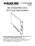
ULTRA COMM+422.PCI
USER MANUAL
TM
Part # 7402
Sealevel Systems, Inc
155 Technology Place
P.O. Box 830
Liberty, SC 29657 USA
Phone: (864) 843-4343
FAX:
(864) 843-3067
www.sealevel.com
Contents
INTRODUCTION ........................................................................ 1
OVERVIEW ...........................................................................................1
WHAT’S INCLUDED..............................................................................1
FACTORY DEFAULT SETTINGS..............................................................1
CARD SETUP............................................................................. 2
RS-485 ENABLE MODES.....................................................................2
Interface Mode Examples J1B –J4B (continued) .......................4
ADDRESS AND IRQ SELECTION.............................................................4
LINE TERMINATION..............................................................................5
BAUD RATES AND DIVISORS FOR THE ‘DIV1’ MODE...........................7
BAUD RATES AND DIVISORS FOR THE ‘DIV2’ MODE...........................8
INSTALLATION.......................................................................... 9
OPERATING SYSTEM INSTALLATION ....................................................9
For Windows Users .......................................................................9
Other Operating Systems ..............................................................9
SYSTEM INSTALLATION .......................................................................9
TECHNICAL DESCRIPTION ..................................................... 10
Interrupts.......................................................................................10
WHY USE AN ISP? .............................................................................11
CONNECTOR P IN ASSIGNMENTS .........................................................12
RS-422/485 (DB 9 Male) ........................................................12
DB-37 Connector Pin Assignments...........................................12
SPECIFICATIONS ..................................................................... 13
ENVIRONMENTAL SPECIFICATIONS.....................................................13
MANUFACTURING..............................................................................13
P OWER CONSUMPTION ......................................................................13
MEAN TIME BETWEEN FAILURES (MTBF) ........................................13
P HYSICAL DIMENSIONS......................................................................13
APPENDIX A - TROUBLESHOOTING ....................................... 14
PCI COM NUMBER SELECTION IN WINDOWS 95/98 .........15
APPENDIX B - HOW TO GET ASSISTANCEERROR! BOOKMARK NOT
DEFINED.
APPENDIX C - ELECTRICAL INTERFACE ................................ 17
RS-422.............................................................................................17
RS-485.............................................................................................17
APPENDIX D - ASYNCHRONOUS COMMUNICATIONS ............ 18
APPENDIX E - SILK-SCREEN .................................................. 19
APPENDIX F - COMPLIANCE NOTICES ................................... 20
FEDERAL COMMUNICATIONS COMMISSION STATEMENT ...................20
EMC DIRECTIVE STATEMENT ...........................................................20
WARRANTY ........................ERROR! BOOKMARK NOT DEFINED.
Figures
Figure 1- Headers J1B – J4B, RS-422............................................................ 3
Figure 2 - Headers J1B – J4B, RS-485 ‘Auto’ Enabled, with ‘No Echo’ ..... 3
Figure 3 - Headers J1B – J4B, RS-485 ‘Auto’ Enabled, with ‘Echo’ ........... 3
Figure 4 - Headers J1B – J4B, RS-485 ‘RTS’ Enabled, with ‘No Echo’ ..... 4
Figure 5 - Headers J1B – J4B, RS-485 ‘RTS’ Enabled, with ‘Echo’ ........... 4
Figure 6 - Headers J1A – J4A, Line Termination.......................................... 5
Figure 7 - Clocking Mode 'Divide By 4’ ......................................................... 6
Figure 8 - Clocking Mode 'Divide By 2’ ......................................................... 6
Figure 9 - Asynchronous Communications Bit Diagram............................... 18
© 2001d Sealevel Systems, Incorporated. All rights reserved.
Introduction
Introduction
Overview
The Sealevel ULTRA COMM+422.PCI is a four channel PCI Bus serial I/O
adapter for the PC and compatibles supporting data rates up to 460.8K bps.
RS-422 provides excellent communications for long distance device
connections up to 4000ft., where noise immunity and high data integrity are
essential. Select RS-485 and capture data from multiple peripherals in a
RS-485 multidrop network.
In both RS-485 and RS-422 modes, the card works seamlessly with the
standard operating system serial driver. In RS-485 mode, our special autoenable feature allows the RS-485 ports to be viewed by the operating system as
a COM: port. This allows the standard COM: driver to be utilized for RS-485
communications. Our on-board hardware automatically handles the RS-485
driver enable
What’s Included
The ULTRA COMM+422.PCI is shipped with the following items. If any of
these items are missing or damaged, contact the supplier.
•
•
•
ULTRA COMM+422.PCI Serial I/O Adapter
Sealevel Software
“Spider” Cable providing 4 DB-9 connectors
Factory Default Settings
The ULTRA COMM+422.PCI factory default settings are as follows:
Port #
Port 1
Port 2
Port 3
Port 4
Clock DIV Mode
4
4
4
4
Enable Mode
Auto
Auto
Auto
Auto
To install the ULTRA COMM+422.PCI using factory default settings, refer to
Installation on page 9.
For your reference, record installed ULTRA COMM+422.PCI settings below:
Port #
Clock DIV Mode
Enable Mode
Port 1
Port 2
Port 3
Port 4
Sealevel Systems ULTRA COMM+422.PCI
Page 1
Card Setup
Card Setup
In all cases J1x is for port 1, J2x - port 2, J3x - port 3 and J4x – port 4.
RS-485 Enable Modes
RS-485 is ideal for multi-drop or network environments. RS-485 requires a
tri-state driver that will allow the electrical presence of the driver to be
removed from the line. The driver is in a tri-state or high impedance condition
when this occurs. Only one driver may be active at a time and the other
driver(s) must be tri-stated. The output modem control signal Request To Send
(RTS) is typically used to control the state of the driver. Some communication
software packages refer to RS-485 as RTS enable or RTS block mode transfer.
One of the unique features of the ULTRA COMM+422.PCI is the ability to be
RS-485 compatible without the need for special software or drivers. This
ability is especially useful in Windows, Windows NT, and OS/2 environments
where the lower level I/O control is abstracted from the application program.
This ability means that the user can effectively use the ULTRA
COMM+422.PCI in an RS-485 application with existing (i.e. standard RS-232)
software drivers.
Headers J1B – J4B are used to control the RS-485 mode functions for the
driver circuit. The selections are ‘RTS’ enable (silk-screen ‘RT’) or ‘Auto’
enable (silk-screen ‘AT’). The ‘Auto’ enable feature automatically
enables/disables the RS-485 interface. The ‘RTS’ mode uses the ‘RTS’
modem control signal to enable the RS-485 interface and provides backward
compatibility with existing software products.
Position 3 (silk-screen ‘NE’) of J1B – J4B is used to control the RS-485
enable/disable functions for the receiver circuit and determine the state of the
RS-422/485 driver. The RS-485 ‘Echo’ is the result of connecting the receiver
inputs to the transmitter outputs. Every time a character is transmitted; it is also
received. This can be beneficial if the software can handle echoing (i.e. using
received characters to throttle the transmitter) or it can confuse the system if
the software does not. To select the ‘No Echo’ mode select silk-screen
position ‘NE’.
For RS-422/530/449 compatibility remove the jumpers at J1B – J4B.
Examples on the following pages describe all of the valid settings for J1B –
J4B.
Sealevel Systems ULTRA COMM+422.PCI
Page 2
Card Setup
AT
RT
NE
Interface Mode Examples J1B – J4B
AT
RT
NE
Figure 1- Headers J1B – J4B, RS-422
AT
RT
NE
Figure 2 - Headers J1B – J4B, RS-485 ‘Auto’ Enabled, with ‘No Echo’
Figure 3 - Headers J1B – J4B, RS-485 ‘Auto’ Enabled, with ‘Echo’
Sealevel Systems ULTRA COMM+422.PCI
Page 3
Card Setup
AT
RT
NE
Interface Mode Examples J1B –J4B (continued)
AT
RT
NE
Figure 4 - Headers J1B – J4B, RS-485 ‘RTS’ Enabled, with ‘No Echo’
Figure 5 - Headers J1B – J4B, RS-485 ‘RTS’ Enabled, with ‘Echo’
Address and IRQ selection
The ULTRA COMM+422.PCI is automatically assigned I/O addresses and
IRQs by your motherboard BIOS. Only the I/O addresses may be modified by
the user. Adding or removing other hardware may change the assignment of I/O
addresses and IRQs.
Sealevel Systems ULTRA COMM+422.PCI
Page 4
Card Setup
Line Termination
Typically, each end of the RS-485 bus must have line terminating resistors
(RS-422 terminates the receive end only). A 120-ohm resistor is across each
RS-530/422/485 input in addition to a 1K ohm pull-up/pull-down combination
that biases the receiver inputs. Headers J1A – J4A allow the user to customize
this interface to their specific requirements. Each jumper position corresponds
to a specific portion of the interface. If multiple ULTRA COMM+422.PCI
adapters are configured in an RS-485 network, only the boards on each end
should have jumpers T, P & P ON. Refer to the following table for each
position’s operation:
Name
P
P
T
L
L
Function
Adds or removes the 1K ohm pull-down resistor in the
RS-422/RS-485 receiver circuit (Receive data only).
Adds or removes the 1K ohm pull-up resistor in the
RS-422/RS-485 receiver circuit (Receive data only).
Adds or removes the 120 ohm termination.
Connects the TX+ to RX+ for RS-485 two wire operation.
Connects the TX- to RX- for RS-485 two wire operation.
P P T L L
Figure 6 - Headers J1A – J4A, Line Termination
Sealevel Systems ULTRA COMM+422.PCI
Page 5
Card Setup
Clock Modes
The ULTRA COMM+422.PCI employs a unique clocking option that allows the
end user to select from divide by 4, divide by 2 and divide by 1 clocking modes.
These modes are selected at Headers J1C through J4C.
DIV1
DIV2
DIV4
To select the Baud rates commonly associated with COM: ports (i.e. 2400,
4800, 9600, 19.2, … 115.2K Bps) place the jumper in the divide by 4 mode
(silk-screen DIV4).
Figure 7 - Clocking Mode 'Divide By 4’
DIV1
DIV2
DIV4
To double these rates up to a maximum rate for 230.4K bps place the jumper in
the divide by 2 (silk-screen DIV2) position.
Figure 8 - Clocking Mode 'Divide By 2’
Sealevel Systems ULTRA COMM+422.PCI
Page 6
Card Setup
Baud Rates and Divisors for the ‘DIV1’ mode
The following table shows some common data rates and the rates you should
choose to match them if using the adapter in the ‘DIV1’ mode.
For this Data Rate
1200 bps
2400 bps
4800 bps
9600 bps
19.2K bps
57.6 K bps
115.2 K bps
230.4K bps
460.8K bps
Choose this Data Rate
300 bps
600 bps
1200 bps
2400 bps
4800 bps
14.4K bps
28.8K bps
57.6 K bps
115.2 K bps
If your communications package allows the use of Baud rate divisors, choose
the appropriate divisor from the following table:
For this Data Rate
1200 bps
2400 bps
4800 bps
9600 bps
19.2K bps
38.4K bps
57.6K bps
115.2K bps
230.4K bps
460.8K bps
Sealevel Systems ULTRA COMM+422.PCI
Choose this Divisor
384
192
96
48
24
12
8
4
2
1
Page 7
Card Setup
Baud Rates and Divisors for the ‘DIV2’ mode
The following table shows some common data rates and the rates you should
choose to match them if using the adapter in the ‘DIV2’ mode.
For this Data Rate
1200 bps
2400 bps
4800 bps
9600 bps
19.2K bps
38.4K bps
57.6 K bps
115.2 K bps
230.4 K bps
Choose this Data Rate
600 bps
1200 bps
2400bps
4800 bps
9600 bps
19.2K bps
28.8K bps
57.6 K bps
115.2 K bps
If your communications package allows the use of Baud rate divisors, choose
the appropriate divisor from the following table:
For this Data Rate
1200 bps
2400 bps
4800 bps
9600 bps
19.2K bps
38.4K bps
57.6K bps
115.2K bps
230.4K bps
Sealevel Systems ULTRA COMM+422.PCI
Choose this Divisor
192
96
48
24
12
8
4
2
1
Page 8
Installation
Installation
Operating System Installation
For Windows Users
Start by choosing Install Software at the beginning of the CD. Choose
Asynchronous COM: Port Software, SeaCOM.
Other Operating Systems
Refer to the appropriate section of the Serial Utilities Software.
System Installation
The ULTRA COMM+422.PCI can be installed in any of the PCI expansion
slots and contains several jumper straps for each port that must be set for
proper operation.
1.
2.
3.
4.
Turn off PC power. Disconnect the power cord.
Remove the PC case cover.
Locate an available PCI slot and remove the blank metal slot cover.
Gently insert the ULTRA COMM+422.PCI into the slot. Make sure that
the adapter is seated properly.
5. Replace the screw.
6. Replace the cover.
7. Connect the power cord.
Installation is complete.
Sealevel Systems ULTRA COMM+422.PCI
Page 9
Technical Description
Technical Description
The Sealevel Systems ULTRA COMM+422.PCI provides a PCI interface
adapter with 4 RS-422/485 asynchronous serial ports for industrial automation
and control applications.
The ULTRA COMM+422.PCI utilizes the 16550 UART. This chip features
programmable baud rates, data format, interrupt control and a 16-byte input and
output FIFO. A full array of advanced UARTS is also available for this card.
Contact Sealevel Systems for more information.
Interrupts
A good description of an interrupt and its importance to the PC can be found in
the book ‘Peter Norton’s Inside the PC, Premier Edition’:
A good analogy of a PC interrupt would be the phone ringing. The phone ‘bell’
is a request for us to stop what we are currently doing and take up another task
(speak to the person on the other end of the line). This is the same process the
PC uses to alert the CPU that a task must be preformed. The CPU upon
receiving an interrupt makes a record of what the processor was doing at the
time and stores this information on the ‘stack’; this allows the processor to
resume its predefined duties after the interrupt is handled, exactly where it left
off. Every main sub-system in the PC has it’s own interrupt, frequently called
an IRQ (short for Interrupt ReQuest).
Sealevel Systems ULTRA COMM+422.PCI
Page 10
Technical Description
In the early days of PC’s Sealevel Systems decided that the ability to share
IRQs was an important feature for any add-in I/O card. Consider that in the IBM
XT the available IRQs were IRQ0 through IRQ7. Of these interrupts only IRQ25 and IRQ7 were actually available for use. This made the IRQ a very valuable
system resource. To make the maximum use of these system resources
Sealevel Systems devised an IRQ sharing circuit that allowed more than one
port to use a selected IRQ. This worked fine as a hardware solution but
presented the software designer with a challenge to identify the source of the
interrupt. The software designer frequently used a technique referred to as
‘round robin polling’. This method required the interrupt servi ce routine to
‘poll’ or interrogate each UART as to its interrupt pending status. This method
of polling was sufficient for use with slower speed communications, but as
modems increased their through put abilities this method of servicing shared
IRQs became inefficient.
Why use an ISP?
The answer to the polling inefficiency was the Interrupt Status Port (ISP). The
ISP is a read only 8-bit register that sets a corresponding bit when an interrupt
is pending. Port 1 interrupt line corresponds with Bit D0 of the status port,
Port 2 with D1 etc. The use of this port means that the software designer now
only has to poll a single port to determine if an interrupt is pending.
The ISP is at Base+7 on each port (Example: Base = 280 Hex, Status Port =
287, 28F… etc.). The ULTRA COMM+422.PCI will allow any one of the
available locations to be read to obtain the value in the status register. Both
status ports on the ULTRA COMM+422.PCI are identical, so any one can be
read.
Example: This indicates that Channel 2 has an interrupt pending.
Bit Position:
Value Read:
7
0
6
0
5
0
4
0
3
0
Sealevel Systems ULTRA COMM+422.PCI
2
0
1
1
0
0
Page 11
Technical Description
Connector Pin Assignments
RS-422/485
Signal
GND
TX +
TXRTS+
RTSRX+
RXCTS+
CTS-
(DB 9 Male)
Name
Ground
Transmit Data Positive
Transmit Data Negative
Request To Send Positive
Request To Send Negative
Receive Data Positive
Receive Data Negative
Clear To Send Positive
Clear To Send Negative
Pin #
5
4
3
6
7
1
2
9
8
Mode
Output
Output
Output
Output
Input
Input
Input
Input
DB-37 Connector Pin Assignments
Port #
GND
TXRTSTX+
RXCTSRTS+
RX+
CTS+
1
33
35
17
34
36
16
18
37
15
2
14
12
30
13
11
31
29
10
32
Sealevel Systems ULTRA COMM+422.PCI
3
24
26
8
25
27
7
9
28
6
4
5
3
21
4
2
22
20
1
23
Page 12
Specifications
Specifications
Environmental Specifications
Specification
Temperature Range
Humidity Range
Operating
0º to 50º C
(32º to 122º F)
10 to 90% R.H.
Non-Condensing
Storage
-20º to 70º C
(-4º to 158º F)
10 to 90% R.H.
Non-Condensing
Manufacturing
•
All Sealevel Systems Printed Circuit boards are built to U. L. 94V0 rating
and are 100% electrically tested. These printed circuit boards are solder
mask over bare copper or solder mask over tin nickel.
Power Consumption
Supply line
Rating
+5 VDC
620 mA
Mean Time Between Failures (MTBF)
Greater than 150,000 hours. (Calculated)
Physical Dimensions
Board length
Board Height including Goldfingers
Board Height excluding Goldfingers
5.0 inches
4.2 inches
3.875 inches
Sealevel Systems ULTRA COMM+422.PCI
(12.7 cm)
(10.66 cm)
(9.841 cm)
Page 13
Appendix A - Troubleshooting
Appendix A - Troubleshooting
Serial Utility test software is supplied with the Sealevel Systems adapter and
will be used in the troubleshooting procedures. By using this software and
following these simple steps, most common problems can be eliminated
without the need to call Technical Support.
1. Identify all I/O adapters currently installed in your system. This includes
your on-board serial ports, controller cards, sound cards etc. The I/O
addresses used by these adapters, as well as the IRQ (if any) should be
identified.
2. Configure your Sealevel Systems adapter so that there is no conflict with
currently installed adapters. No two adapters can occupy the same I/O
address.
3. Make sure the Sealevel Systems adapter is using a unique IRQ The IRQ is
typically selected via an on-board header block. Refer to the section on
Card Setup for help in choosing an I/O address and IRQ.
4. Make sure the Sealevel Systems adapter is securely installed in a
motherboard slot.
5. When running DOS, Windows 3.x or other operating systems refer to the
Sealevel software for that operating system and the User Manual to verify
that the Sealevel Systems adapter is configured correctly. The supplied
software contains a diagnostic program 'SSD' that runs under DOS and will
verify if an adapter is configured properly. This diagnostic program is
written with the user in mind and is easy to use. Refer to the DIAG.txt file
in the dos\diag directory for detailed instructions on using 'SSD'.
6. For Windows 95/98 and Windows NT, the diagnostic tool 'WinSSD' is
installed in the Sealevel folder on the Start Menu during the setup process.
First find the ports using the Device Manager, then use 'WinSSD' to verify
that the ports are functional.
7. Always use the Sealevel Systems diagnostic software when
troubleshooting a problem. This will help eliminate any software issues
and identify any hardware conflicts.
Sealevel Systems ULTRA COMM+422.PCI
Page 14
Appendix A - Troubleshooting
PCI COM NUMBER SELECTION IN WINDOWS 95/98
When installing a multi-port PCI card in Windows 95 the default starting COM:
number assigned to the first port will be COM:5 if no COM:5 exists. If there is
a COM: 5, 6, etc., the next available COM: number will be assigned to the first
port with all additional ports following in ascending order.
To change the first two ports so that Windows assigns them COM: 3 and COM:
4 port enumeration double click the Systems icon in control panel or right
click on My Computer and choose properties which will bring you to System
Properties. Choose the Device Manager tab and double click on the MultiFunction Adapter heading. This will show all the information concerning the
Sealevel adapter. Choose the Resources tab, which will show all resources
assigned to the multi-function adapter. Uncheck the Use Automatic Settings
box. Notice that with a two port card there will be three input/output, (I/O),
ranges listed. With a four port card there will be five input/output, (I/O), ranges
listed. The first I/O range is for the PCI bus and should not be changed. The
second and third I/O ranges are the ones that need to be changed in order to
have those ports enumerated as COM: 3 and COM: 4. Double click on the
second I/O range which will allow you to change the address. Highlight the
entire I/O range and type: 03e8–03ef for COM: 3. Click OK. Windows will
inform you that you have made modifications that may affect other devices.
Click OK. Next double click on the third I/O range. Highlight the entire I/O
range and type: 02e8–02ef for COM: 4. Again Windows will inform you that
you have made modifications that may affect other devices. Click OK.
Following these steps will change the COM: number assignments on the first
two ports to
COM: 3 and 4.
Sealevel Systems ULTRA COMM+422.PCI
Page 15
Appendix B - How To Get Assistance
Appendix B - How To Get Assistance
1. Begin by reading through the Trouble Shooting Guide in Appendix
A. If assistance is still needed please see below.
2. When calling for technical assistance, please have your user
manual and current adapter settings. If possible, please have the
adapter installed in a computer ready to run diagnostics.
3. Sealevel Systems provides an FAQ section on its web site. Please
refer to this for many commonly asked questions. This section
can be found at http://www.sealevel.com/faq.htm .
4. Visit Sealevel’s website at www.sealevel.com for the latest
software updates and newest manuals.
5. Technical support is available Monday to Friday from 8:00 a.m. to
5:00 p.m. eastern time. Technical support can be reached at (864)
843-4343.
RETURN AUTHORIZATION MUST BE OBTAINED FROM SEALEVEL
SYSTEMS BEFORE RETURNED MERCHANDISE WILL BE ACCEPTED.
AUTHORIZATION CAN BE OBTAINED BY CALLING SEALEVEL
SYSTEMS AND REQUESTING A RETURN MERCHANDISE
AUTHORIZATION (RMA) NUMBER.
Sealevel Systems ULTRA COMM+422.PCI
Page 16
Appendix C – Electrical Interface
Appendix C - Electrical Interface
RS-422
The RS-422 specification defines the electrical characteristics of balanced
voltage digital interface circuits. RS-422 is a differential interface that defines
voltage levels and driver/receiver electrical specifications. On a differential
interface, logic levels are defined by the difference in voltage between a pair of
outputs or inputs. In contrast, a single ended interface, for example RS-232,
defines the logic levels as the difference in voltage between a single signal and
a common ground connection. Differential interfaces are typically more
immune to noise or voltage spikes that may occur on the communication lines.
Differential interfaces also have greater drive capabilities that allow for longer
cable lengths. RS-422 is rated up to 10 Megabits per second and can have
cabling 4000 feet long. RS-422 also defines driver and receiver electrical
characteristics that will allow 1 driver and up to 32 receivers on the line at
once. RS-422 signal levels range from 0 to +5 volts. RS-422 does not define a
physical connector.
RS-485
RS-485 is backwardly compatible with RS-422; however, it is optimized for
partyline or multi-drop applications. The output of the RS-422/485 driver is
capable of being Active (enabled) or Tri-State (disabled). This capability allows
multiple ports to be connected in a multi-drop bus and selectively polled.
RS-485 allows cable lengths up to 4000 feet and data rates up to 10 Megabits
per second. The signal levels for RS-485 are the same as those defined by
RS-422. RS-485 has electrical characteristics that allow for 32 drivers and 32
receivers to be connected to one line. This interface is ideal for multi-drop or
network environments. RS-485 tri-state driver (not dual-state) will allow the
electrical presence of the driver to be removed from the line. Only one driver
may be active at a time and the other driver(s) must be tri-stated. RS-485 can be
cabled in two ways, two wire and four wire mode. Two wire mode does not
allow for full duplex communication, and requires that data be transferred in
only one direction at a time. For half-duplex operation, the two transmit pins
should be connected to the two receive pins (Tx+ to Rx+ and Tx- to Rx-). Four
wire mode allows full duplex data transfers. RS-485 does not define a
connector pin-out or a set of modem control signals. RS-485 does not define a
physical connector.
Sealevel Systems ULTRA COMM+422.PCI
Page 17
Appendix D - Asynchronous Communications
Appendix D - Asynchronous Communications
Serial data communications implies that individual bits of a character are
transmitted consecutively to a receiver that assembles the bits back into a
character. Data rate, error checking, handshaking, and character framing
(start/stop bits) are pre-defined and must correspond at both the transmitting
and receiving ends.
Asynchronous communications is the standard means of serial data
communication for PC compatibles and PS/2 computers. The original PC was
equipped with a communication or COM: port that was designed around an
8250 Universal Asynchronous Receiver Transmitter (UART). This device
allows asynchronous serial data to be transferred through a simple and
straightforward programming interface. A start bit, followed by a pre-defined
number of data bits (5, 6, 7, or 8) defines character boundaries for
asynchronous communications. The end of the character is defined by the
transmission of a pre-defined number of stop bits (usually 1, 1.5 or 2). An extra
bit used for error detection is often appended before the stop bits.
Idle state of
line
Odd, Even
5 to 8 Data Bits
or
Unused
Remain Idle or
next start bit
1
P
STOP
BIT
0
1
1.5
2
Figure 9 - Asynchronous Communications Bit Diagram
This special bit is called the parity bit. Parity is a simple method of determining
if a data bit has been lost or corrupted during transmission. There are several
methods for implementing a parity check to guard against data corruption.
Common methods are called (E)ven Parity or (O)dd Parity. Sometimes parity
is not used to detect errors on the data stream. This is refereed to as (N)o
parity. Because each bit in asynchronous communications is sent
consecutively, it is easy to generalize asynchronous communications by stating
that each character is wrapped (framed) by pre-defined bits to mark the
beginning and end of the serial transmission of the character. The data rate and
communication parameters for asynchronous communications have to be the
same at both the transmitting and receiving ends. The communication
parameters are baud rate, parity, number of data bits per character, and stop bits
(i.e.
9600,N,8,1).
Sealevel Systems ULTRA COMM+422.PCI
Page 18
Appendix E - Silk-Screen
Appendix E - Silk-Screen
4.2"
5.2"
Sealevel Systems ULTRA COMM+422.PCI
Page 19
Appendix F - Compliance Notices
Appendix F - Compliance Notices
Federal Communications Commission Statement
FCC - This equipment has been tested and found to comply with the limits for
Class A digital device, pursuant to Part 15 of the FCC Rules. These limits are
designed to provide reasonable protection against harmful interference when
the equipment is operated in a commercial environment. This equipment
generates, uses, and can radiate radio frequency energy and, if not installed and
used in accordance with the instruction manual, may cause harmful interference
to radio communications. Operation of this equipment in a residential area is
likely to cause harmful interference in such case the user will be required to
correct the interference at his own expense.
EMC Directive Statement
Products bearing the CE Label fulfill the requirements of the
EMC directive (89/336/EEC) and of the low-voltage directive
(73/23/EEC) issued by the European Commission.
To obey these directives, the following European standards must be met:
•
EN55022 Class A - “Limits and methods of measurement of radio
interference characteristics of information technology equipment”
•
EN55024-‘Information
technology
equipment
characteristics Limits and methods of measurement.
Immunity
•
EN60950 (IEC950) - “Safety of information
equipment, including electrical business equipment”
technology
Warning
This is a Class A Product. In a domestic environment this product may cause
radio interference in which case the user may be required to take adequate
measures.
Always use cabling provided with this product if possible. If no cable is
provided or if an alternate cable is required, use high quality shielded cabling to
maintain compliance with FCC/EMC directives.
Sealevel Systems ULTRA COMM+422.PCI
Page 20
Warranty
Warranty
Sealevel Systems, Inc. provides a limited lifetime
warranty. Should this product fail to be in good
working order at any time during this period, Sealevel
Systems will, at it’s option, replace or repair it at no
additional charge except as set forth in the following
terms. This warranty does not apply to products damaged by misuse,
modifications, accident or disaster.
Sealevel Systems assumes no liability for any damages, lost profits, lost
savings or any other incidental or consequential damage resulting from the use,
misuse of, or inability to use this product. Sealevel Systems will not be liable
for any claim made by any other related party.
RETURN AUTHORIZATION MUST BE OBTAINED FROM SEALEVEL
SYSTEMS BEFORE RETURNED MERCHANDISE WILL BE ACCEPTED.
AUTHORIZATION CAN BE OBTAINED BY CALLING SEALEVEL
SYSTEMS AND REQUESTING A RETURN MERCHANDISE
AUTHORIZATION (RMA) NUMBER.
Sealevel Systems, Incorporated
155 Technology Place
P.O. Box 830
Liberty, SC 29657 USA
(864) 843-4343 FAX:(864) 843-3067
www.sealevel.com
email: [email protected]
Technical Support is available from 8 a.m. to 5 p.m. Eastern time.
Monday - Friday
Trademarks
Sealevel Systems, Incorporated acknowledges that all trademarks referenced in
this manual are the service mark, trademark, or registered trademark of the
respective company.
ULTRA COMM+422.PCI is a trademark of Sealevel Systems, Incorporated.
Sealevel Systems ULTRA COMM+422.PCI
Page 21