1
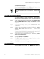
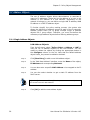
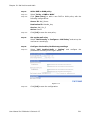
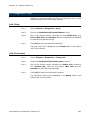
SifoWorks U-Series 4.05
User Manual
OD7300UME01–4
Notice
No part of this document may be reproduced or transmitted in any form or by any means, electronic or
mechanical, for any purpose, without receiving written permission from O2Security.
O2Security and its subsidiaries reserve the right to make changes to their documents and/or products or to
discontinue any product or service without notice, and advise customers to obtain the latest version of relevant
information to verify, before placing orders, that information being relied on is current and complete. All products
are sold subject to the terms and conditions of sale supplied at the time of order acknowledgement, including
those pertaining to warranty, patent infringement, and limitation of liability.
O2Security warrants performance of its products to the specifications applicable at the time of sale in accordance with O2Security’s standard warranty. Testing and other quality control techniques are utilized to the
extent O2Security deems necessary to support this warranty. Specific testing of all parameters of each device is
not necessarily performed, except those mandated by government requirements.
Customer acknowledges that O2Security products are not designed, manufactured or intended for incorporation
into any systems or products intended for use in connection with life support or other hazardous activities or
environments in which the failure of the O2Security products could lead to death, bodily injury, or property or
environmental damage ("High Risk Activities"). O2Security hereby disclaims all warranties, and O2Security will
have no liability to Customer or any third party, relating to the use of O2Security products in connection with any
High Risk Activities.
Any support, assistance, recommendation or information (collectively, "Support") that O2Security may provide to
you (including, without limitation, regarding the design, development or debugging of your circuit board or other
application) is provided "AS IS." O2Security does not make, and hereby disclaims, any warranties regarding any
such Support, including, without limitation, any warranties of merchantability or fitness for a particular purpose,
and any warranty that such Support will be accurate or error free or that your circuit board or other application
will be operational or functional. O2Security will have no liability to you under any legal theory in connection with
your use of or reliance on such Support.
Information in this document is subject to change without notice.
©2008 O2Security Ltd., an O2Micro International Ltd. company (NASDAQ: OIIM, SEHK: 0457). All rights
reserved. O2Security is a trademark and SifoWorks is a registered trademark of O2Micro International Ltd.
Table of Contents
Product Overview.................................................................................... 1
What is SifoWorks UTM?................................................................................1
SifoWorks U-series Security Mechanisms .........................................................2
Device Ports and LEDs ..................................................................................4
Differences in SifoWorks U-Series models ...................................................... 14
Getting Started......................................................................................17
Logging into the System.............................................................................. 17
Logging Out from the System ...................................................................... 18
1. Administrator Management ................................................................19
1.1 Administrator Accounts.......................................................................... 19
1.2 Permitted Login IPs ............................................................................... 21
2. Basic System Configurations...............................................................23
2.1
2.2
2.3
2.4
2.5
Basic Settings ...................................................................................... 23
System Date and Time Settings .............................................................. 27
Language Settings ................................................................................ 28
Software Update ................................................................................... 28
SNMP .................................................................................................. 29
3. Network Settings ..............................................................................31
3.1
3.2
3.3
3.4
3.5
3.6
3.7
SifoWorks U-series Operating Modes ....................................................... 31
Configuring the Physical Interfaces .......................................................... 33
Configuring Multiple Subnets .................................................................. 39
Route Table ......................................................................................... 41
Setting DHCP ....................................................................................... 42
Dynamic DNS ....................................................................................... 43
Host Table ........................................................................................... 44
4. Firewall Policy Management ................................................................45
4.1
4.2
4.3
4.4
4.5
4.6
4.7
Outgoing Policies .................................................................................. 45
Incoming Policies .................................................................................. 49
WAN to DMZ Policies ............................................................................. 52
LAN to DMZ Policies .............................................................................. 52
DMZ to WAN Policies ............................................................................. 55
DMZ to LAN Policies .............................................................................. 55
Application Examples............................................................................. 56
5. Policy Object Management .................................................................57
5.1
5.2
5.3
5.4
5.5
5.6
Address Objects.................................................................................... 58
Service Objects .................................................................................... 63
Schedule Objects .................................................................................. 66
Quality of Service ................................................................................. 68
Content Blocking Objects ....................................................................... 71
Application Blocking .............................................................................. 77
6. Authentication ..................................................................................81
6.1
6.2
6.3
6.4
6.5
6.6
Internal Authentication Server Settings.................................................... 81
Using an External RADIUS Server............................................................ 82
Using an External POP3 Server ............................................................... 84
LDAP Server......................................................................................... 85
Authentication Users ............................................................................. 87
Authentication User Groups .................................................................... 88
7. Virtual Service ..................................................................................91
7.1 Mapped IP ........................................................................................... 91
7.2 One-to-Many Virtual Server Mappings ...................................................... 94
8. IPsec VPN ...................................................................................... 101
8.1
8.2
8.3
8.4
8.5
8.6
8.7
8.8
One-Step IPsec VPN ............................................................................ 101
VPN Wizard ........................................................................................ 102
IPsec AutoKey .................................................................................... 103
CA Certificates.................................................................................... 117
Local Certificates ................................................................................ 117
PPTP Server ....................................................................................... 119
PPTP Client ........................................................................................ 121
Trunk ................................................................................................ 129
9. Policy and Objects - More Application Examples................................... 131
9.1
9.2
9.3
9.4
Application
Application
Application
Application
Example
Example
Example
Example
1 ......................................................................... 131
2 ......................................................................... 133
3 ......................................................................... 135
4 ......................................................................... 137
10. SSL VPN ........................................................................................ 143
10.1 Basic SSL VPN Configuration............................................................... 143
10.2 SSL VPN Hardware Authentication ....................................................... 146
10.3 SSL VPN Connection Status ................................................................ 146
11. Mail Security .................................................................................. 147
11.1
11.2
11.3
11.4
11.5
11.6
11.7
Configuring the Basic Settings ............................................................ 147
Mail Relay ........................................................................................ 149
Mail Account..................................................................................... 153
Mail Notice ....................................................................................... 156
Anti-Spam ....................................................................................... 163
Anti-Virus ........................................................................................ 186
Mail Report ...................................................................................... 194
12. Mail Archive and Audit ..................................................................... 197
12.1 Mail Archive and Audit Settings ........................................................... 197
12.2 Mail Audit Rules ................................................................................ 198
12.3 Archived Mails .................................................................................. 203
13. Intrusion Detection and Prevention.................................................... 205
13.1 Basic IDP Settings ............................................................................. 205
13.2 IDP Signatures ................................................................................. 207
13.3 IDP Log Report ................................................................................. 210
14. Anomaly Flow IP ............................................................................. 213
14.1 Basic Settings................................................................................... 213
14.2 Anomaly Flow IP Log ......................................................................... 214
15. Advanced Options ........................................................................... 215
15.1 Inbound Balance ............................................................................... 215
15.2 High Availability ................................................................................ 225
15.3 Co-Defense System ........................................................................... 229
16. System Monitoring .......................................................................... 233
16.1
16.2
16.3
16.4
16.5
16.6
Logs................................................................................................ 233
Report ............................................................................................. 239
Statistics ......................................................................................... 242
Diagnostic Tools................................................................................ 245
Wake on LAN.................................................................................... 246
System Status .................................................................................. 246
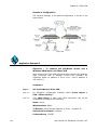
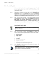
Product Overview
This chapter describes the network ports, LEDs and performance
indexes for each SifoWorks UTM (Unified Threat Management), USeries model. It also introduces the various functions available in
the SifoWorks UTM product family and the differences between
each UTM model.
What is SifoWorks UTM?
SifoWorks UTM (Unified Threat Management) is a comprehensive
network security solution, integrating anti-virus, intrusion detection
and prevention (IDP), IDP co-defense systems, QoS bandwidth
management, bi-directional load balancing, anti-spam, content
filtering, statistical reports and traffic analysis charts and SSL VPN
functions within a single device.
The SifoWorks UTM product family comprises of the following
models:
•
SifoWorks U100
•
SifoWorks U200/200A
•
SifoWorks U210/210A
•
SifoWorks U310/310A
•
SifoWorks U500/500A
•
SifoWorks U510/510A
This manual is valid for UI version 4.05 for all models in the
SifoWorks UTM product family. The term “SifoWorks U-series” will
be used to refer to all SifoWorks UTM models in the following parts
of this manual.
User Manual for SifoWorks U-Series 4.05
1
Product Overview
SifoWorks U-series Security Mechanisms
SifoWorks U-series comprises of several security mechanisms
including:
•
Anti-Virus
SifoWorks U-series is able to perform real-time scans on traffic of
various protocols such as HTTP, FTP, POP3 and SMTP etc,
protecting the internal network from virus, worms or other
malicious software that may be embedded within web pages or
emails.
SifoWorks U-series supports two anti-virus engines: Clam and
Sophos. The Clam engine can be automatically updated an
unlimited number of times, ensuring the accuracy of the system’s
anti-virus scanning mechanism.
•
Intrusion Detection and Prevention (IDP)
SifoWorks U-series’ IDP function is equipped to detect and block up
to 2900 well known attacks. The system’s IDP definition database
can be updated online free of charge. Administrators can also add
customized attack definitions into the system, adapting the system
to recognize ever-changing threats.
The system can be set up to notify users when certain attacks occur
and provide detailed statistical reports to facilitate the tracing of
each attack source.
•
Co-operative Defense Mechanism
When an attack is detected (anomaly traffic flow), the system can
co-operate with a third party router/switch deployed within the
internal network to block traffic from the corresponding source IP.
Thus, prompt action is taken to block large number of attack
packets from being sent into the internal network, preventing such
attacks from crippling the network.
•
QoS Bandwidth Management
SifoWorks U-series provides a quality of service (QoS) function,
managing bandwidth utilization by specifying maximum and
guaranteed bandwidth allocation to certain application services and
servers. The system is also equipped with a packet priority queue
capability.
Administrators can also effectively allocate network resources by
limiting the maximum download bandwidth and session number for
each source IP.
2
User Manual for SifoWorks U-Series 4.05
Product Overview
•
Bi-directional Load Balancing
SifoWorks U-series is equipped with powerful traffic load balancing
capabilities. For inbound traffic, the system is able to balance traffic
load for internal web, mail and other specific servers. For outbound
traffic, the system supports multi-ISP links and various load
balancing modes. Administrators can also define policy routes,
effectively managing bandwidth utilization while ensuring network
stability and reliability.
•
Anti-spam Mail Filtering
SifoWorks U-series’ comprehensive anti-spam function is easily
adaptable to the existing network structure through its two working
modes: transparent mode and forwarding mode. Multiple scanning
mechanisms such as Bayesian filtering, fingerprint database,
network RBL (Real-time Blackhole list) database, greylist etc. Users
can also customize mail filtering rules and set up their
white/blacklists.
Through the use of mail subject headings and notification mails,
users can check the list of detected spam mails, retrieving any
mails that may have been wrongly detected as spam. An automatic
training mechanism is also incorporated, allowing the system to
automatically learn from such errors, greatly enhancing the
accuracy of spam mail detection.
With SifoWorks U-series unique auto-training mechanism, the
accuracy of the system’s spam mail detection can reach up to 99%
or above without administrators having to continuously add new
keywords or spam mail filter rules.
•
Content Filtering
SifoWorks U-series can be set up to recognize and restrict traffic
from commonly used IM (instant messaging) or P2P (peer-to-peer)
applications, preventing such traffic from hogging network
bandwidth or causing security loopholes. These include MSN, QQ,
Skype, ICQ, BT, eDonkey etc. Thus, administrators can easily
manage the usage of such software within the network.
Administrators can filter and block HTTP and FTP traffic contents,
restrict the downloading or uploading of specific types of files and
block scripts such as ActiveX, Java, and Cookies etc, that are
embedded within web pages.
•
Statistical Reports and Traffic Analysis Charts
Various reports and logs can be generated by the system including
anti-virus logs, IDP logs, anti-spam statistical reports, interface
traffic analysis charts (MRTG – Multi Router Traffic Grapher) and
Top N statistic charts etc.
User Manual for SifoWorks U-Series 4.05
3
Product Overview
The system can also send SNMP and email alert notifications,
updating administrators on device status and facilitating auditing of
specific network events.
•
Built-in SSL VPN
Aside from IPsec VPN and PPTP VPN, SifoWorks U-series also
provides SSL VPN, a most convenient remote access solution to
meet the growing demands of a mobile office. Remote users can
connect to and access internal resources via a standard web
browser, greatly reducing administrators’ maintenance workload
while raising the efficiency of the enterprise’s employees.
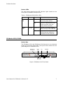
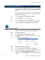
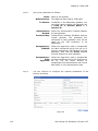
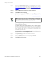
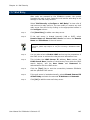
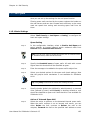
Device Ports and LEDs
This section introduces the ports and LEDs for each model in the
SifoWorks U-series product family.
SifoWorks U100
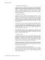
Device Box
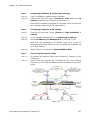
The front panel of SifoWorks U100 is drawn in the figure below
LAN
Power LED
R
2
Breathing Life into Security TM
WAN1
WAN2
LAN
DMZ
Power
SifoWorks U100
Status
WAN
DMZ
Status LED
Figure 1
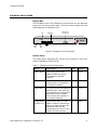
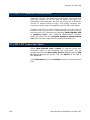
The rear panel of SifoWorks U100 is drawn in the figure below
Console Port
Power Socket
DTE, 115200, n, 8, 1
Figure 2
4
User Manual for SifoWorks U-Series 4.05
Product Overview
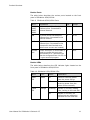
Device Ports
The table below lists the various ports located on the front panel of
SifoWorks U100.
Table 1 SifoWorks U100 Ports
Name
Explanation
No.
Format
WAN1, WAN2
10M/100M self-adaptive Ethernet
ports. Connected to external
network
2
RJ-45
LAN
10/100M self-adaptive Ethernet
port. Connected to the internal
network.
1
RJ-45
DMZ
10/100M self-adaptive Ethernet
port. Connected to the
enterprise’s demilitarized zone
(where core servers are located)
1
RJ-45
Management
Console Port
RS232 serial port. A serial cable
is used to connect this port to an
administrative PC. SifoWorks can
then be configured from this PC
via a hyper-terminal program
1
DB-9
The management console port is
located at the back panel of the
SifoWorks U100 device.
Device LEDs
The table below describes the LED indicator lights located on the
front panel of SifoWorks U100.
Table 2 SifoWorks U100 LEDs
Name
Color
Status
Explanation
Power
LED
Green
On
Device is receiving power
from the power source
Off
Device is switched off or not
receiving power from the
power source normally
Flickering
System is booting up
Off
System is operating normally
or switched off.
Status
LED
User Manual for SifoWorks U-Series 4.05
Green
5
Product Overview
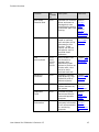
SifoWorks U200/U200A
The front panel of SifoWorks U200 and SifoWorks U200A are
identical except for the device name label. The figure below shows
the front panel diagram of SifoWorks U200.
Power
LED
LAN
DMZ
R
2
Breathing Life into Security TM
LAN
WAN1
WAN2
DMZ
DTE,9600,n,8,1
Power
SifoWorks U200
H.Disk
Management
Console Port
HDD
LED
WAN
Figure 3
Device Ports
The table below describes the various ports located on the front
panel of SifoWorks U200/U200A.
Table 3 SifoWorks U200/U200A Ports
6
Name
Explanation
No.
Format
WAN1, WAN2
10M/100M self-adaptive
Ethernet ports. Connected to
external network
2
RJ-45
LAN
10/100M self-adaptive
Ethernet port. Connected to
the internal network.
1
RJ-45
DMZ
10/100M self-adaptive
Ethernet port. Connected to
the enterprise’s demilitarized
zone (where core servers are
located)
1
RJ-45
Management
Console Port
RS232 serial port. A serial
cable is used to connect this
port to an administrative PC.
SifoWorks can then be
configured from this PC via a
hyper-terminal program
1
DB-9
User Manual for SifoWorks U-Series 4.05
Product Overview
Device LEDs
The table below describes the LED indicator lights located on the
front panel of SifoWorks U200/U200A.
Table 4 SifoWorks U200/U200A LEDs
Name
Color
Status
Explanation
Power
LED
Green
On
Device is receiving power
from the power source
Off
Device is switched off or not
receiving power from the
power source normally
Flickering
System is currently reading
from /writing to the hard disk
Off
System is currently not
performing any read/write
operation on the hard disk.
H.Disk
LED
Orange
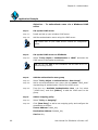
SifoWorks U210/U210A
Device Box
The SifoWorks U210 and SifoWorks U210A device box are identical
except for the device name label. The figure below shows the front
panel diagram of SifoWorks U210.
Power
LED
Management
Console Port
SifoWorksTM U210
LAN
WAN/DMZ
USB
DTE,9600,n,8,1
Power
LAN
WAN1
WAN2
WAN3/DMZ
O2Security
H.Disk
HDD USB
LED Port
WAN
Figure 4 SifoWorks U210 Front Panel
User Manual for SifoWorks U-Series 4.05
7
Product Overview
Device Ports
The various ports located on the front panel of SifoWorks
U210/U210A are described below.
Table 5 SifoWorks U210/U210A Ports
Name
Explanation
No.
Format
WAN1, WAN2
10M/100M/1000M self-adaptive
Ethernet ports. Connected to
external network
2
RJ-45
LAN
10/100M/1000M self-adaptive
Ethernet port. Connected to
the internal network.
1
RJ-45
WAN3/DMZ
10/100M/1000M self-adaptive
Ethernet port. Can be
connected to the enterprise’s
demilitarized zone (where core
servers are located) or the
external network
1
RJ-45
USB
Reserved for future use
2
USB
Management
Console Port
RS232 serial port. A serial
cable is used to connect this
port to an administrative PC.
SifoWorks can then be
configured from this PC via a
hyper-terminal program
1
DB-9
Device LEDs
This table describes the LED indicator lights located on the front
panel of SifoWorks U210/U210A.
Table 6 SifoWorks U210/U210A LEDs
Name
Color
Status
Explanation
Power
LED
Green
On
Device is receiving power
from the power source
Off
Device is switched off or not
receiving power from the
power source normally
Flickering
System is currently reading
from /writing to the hard disk
Off
System is currently not
performing any read/write
operation on the hard disk.
H.Disk
LED
8
Orange
User Manual for SifoWorks U-Series 4.05
Product Overview
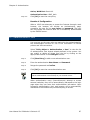
SifoWorks U310/U310A
Device Box
The SifoWorks U310 and SifoWorks U310A device box are identical
except for the device name label. The figure below shows the front
panel diagram of SifoWorks U310.
LAN
WAN/DMZ
Management
Console Port
TM
SifoWorks U310
LAN
WAN1
WAN2
O2Security
WAN3/DMZ
DTE,9600,n,8,1
Power HD
Power
LED
HDD
LED
WAN
Figure 5 SifoWorks U310 Front Panel
Device Ports
The table below describes the various ports located on the front
panel of SifoWorks U310/U310A.
Table 7 SifoWorks U310/U310A Ports
Name
Explanation
No.
Format
WAN1, WAN2
10M/100M/1000M selfadaptive Ethernet ports.
Connected to external
network
2
RJ-45
LAN
10/100M/1000M self-adaptive
Ethernet port. Connected to
the internal network
1
RJ-45
WAN3/DMZ
10/100M/1000M self-adaptive
Ethernet port. Can either be
connected to the enterprise’s
demilitarized zone (where
core servers are located) or
an external network
1
RJ-45
Management
RS232 serial port. A serial
cable is used to connect this
port to an administrative PC.
SifoWorks can then be
configured from this PC via a
hyper-terminal program
1
DB-9
Console Port
User Manual for SifoWorks U-Series 4.05
9
Product Overview
Device LEDs
The LED indicator lights located on the front panel of SifoWorks
U310/U310A are described in the table below.
Table 8 SifoWorks U310/U310A LEDs
Name
Color
Status
Explanation
Power
LED
Green
On
Device is receiving power
from the power source
Off
Device is switched off or not
receiving power from the
power source normally
Flickering
System is currently reading
from /writing to the hard disk
Off
System is currently not
performing any read/write
operation on the hard disk.
H.Disk
LED
Orange
SifoWorks U500/U500A
Device Box
The SifoWorks U500 and SifoWorks U500A device box are identical
except for the device name label. The figure below shows the front
panel diagram of SifoWorks U500.
LAN
DMZ
Power
LED
R
2
Breathing Life into SecurityTM
TM
SifoWorks -U500
LAN
DTE,9600,n,8,1
WAN1
WAN2
WAN3
WAN4
DMZ
Power
H.Disk
Management
Console Port
WAN
HDD
LED
Figure 6 SifoWorks U500 Front Panel
10
User Manual for SifoWorks U-Series 4.05
Product Overview
Device Ports
The table below describes the various ports located on the front
panel of SifoWorks U500/U500A.
Table 9 SifoWorks U500/U500A Ports
Name
Explanation
No.
Format
WAN1,
WAN2,
WAN3,
WAN4,
10M/100M/1000M self-adaptive
Ethernet ports. Connected to
external network
4
RJ-45
LAN
10/100M/1000M self-adaptive
Ethernet port. Connected to the
internal network.
1
RJ-45
DMZ
10/100M/1000M self-adaptive
Ethernet port. Connected to the
enterprise’s demilitarized zone
(where core servers are located)
1
RJ-45
Console
Port
RS232 serial port. A serial cable is
used to connect this port to an
administrative PC. SifoWorks can
then be configured from this PC via
a hyper-terminal program
1
DB-9
Device LEDs
The table below describes the LED indicator lights located on the
front panel of SifoWorks U500/U500A.
Table 10 SifoWorks U500/U500A LEDs
Name
Color
Status
Explanation
Power
LED
Green
On
Device is receiving power
from the power source
Off
Device is switched off or not
receiving power from the
power source normally
Flickering
System is currently reading
from /writing to the hard disk
Off
System is currently not
performing any read/write
operation on the hard disk.
H.Disk
LED
User Manual for SifoWorks U-Series 4.05
Orange
11
Product Overview
SifoWorks U510/U510A
Device Box
The SifoWorks U510 and SifoWorks U510A device box are identical
except for the device name label. The figure below shows the front
panel diagram of SifoWorks U510.
LAN
WAN/DMZ
USB Port
TM
SifoWorks U510
LAN
WAN1
WAN2
WAN3
WAN4
WAN5
O2Security
USB
DMZ/WAN6
DTE,9600,n,8,1
Power HD
Power
LED
HDD
LED
Management
Console Port
WAN
Figure 7 SifoWorks U510 Front Panel
Device Ports
The table below describes the various ports located on the front
panel of SifoWorks U510/U510A.
Table 11 SifoWorks U510/U510A Ports
12
Name
Explanation
No.
Format
WAN1,
WAN2,
WAN3,
WAN4,
WAN5
10M/100M/1000M self-adaptive
Ethernet ports. Connected to
external network
5
RJ-45
LAN
10/100M/1000M self-adaptive
Ethernet port. Connected to the
internal network.
1
RJ-45
DMZ
10/100M/1000M self-adaptive
Ethernet port. Connected to the
enterprise’s demilitarized zone
(where core servers are located)
1
RJ-45
USB
Reserved for future use
2
USB
Console
Port
RS232 serial port. A serial cable is
used to connect this port to an
administrative PC. SifoWorks can
then be configured from this PC via
a hyper-terminal program
1
DB-9
User Manual for SifoWorks U-Series 4.05
Product Overview
Device LEDs
The table below describes the LED indicator lights located on the
front panel of SifoWorks U510/U510A.
Table 12 SifoWorks U510/U510A LEDs
Name
Color
Status
Explanation
Power
LED
Green
On
Device is receiving power
from the power source
Off
Device is switched off or not
receiving power from the
power source normally
Flickering
System is currently reading
from /writing to the hard disk
Off
System is currently not
performing any read/write
operation on the hard disk.
H.Disk
LED
User Manual for SifoWorks U-Series 4.05
Orange
13
Product Overview
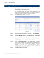
Differences in SifoWorks U-Series models
The SifoWorks UTM product family comprises of models each
aiming to best cater to the needs of enterprises of varying sizes.
Other than differences in hardware capacities such as supporting
different number of users, sessions etc, software functionality
differences also exist between the different models. Thus, the
SifoWorks UTM family provides flexibility of choice to enterprises to
select the model best suited to its needs.
Table 13 below lists the main function groups that are not available
on all models of the SifoWorks UTM product family.
Table 13 Function Group Differences between Models
Function
Not
Available
On
Description
Reference
LDAP
Authentication
Servers
U100
This function allows
the system to use
LDAP authentication
servers.
Section “6.4
LDAP
Server”
IPsec VPN
Wizard
U100
The VPN wizard
provides
administrators with a
simple method of
configuring a basic
IPsec VPN.
Section “8.2
VPN
Wizard”
CA/Local
Certificates
U100,
U200,
U200A,
U210,
U210A,
U310,
U310A
Certificates can be
used to authenticate
VPN users attempting
to connect to the
system.
Section “8.4
CA
Certificates”
U100
Provides users with a
web-based SSL VPN
solution
Chapter “10
SSL VPN”
Administrators can
manage which email
accounts are to be
scanned for spam and
virus
Section
“11.3 Mail
Account”
This function is to set
up the system to
send spam/virus
notification mails
periodically to specific
email addresses.
Section
“11.4 Mail
Notice”
SSL VPN
Mail Accounts
Mail Notice
14
U100
U100
2
2
2
Section “8.5
Local
Certificates”
2
2
2
User Manual for SifoWorks U-Series 4.05
Product Overview
Function
Not
Available
On
Description
Reference
Anti-Spam
Personal Rule
U100
Personal rule function
allows end-users to
manage their own
white/blacklist emails
to facilitate spam mail
filtering.
Section
“11.4.1
Personal
Rule”
Statistical reports
based on network
mail activities will be
generated by this
function. These
reports can also be
periodically sent to
specified email
addresses.
Section
“11.7 Mail
Report”
Mail Reports
U100
Section
“11.5.3
Spam Rules
– Personal”
2
Mail
Archive/Audit
U100,
U200,
U200A,
U210,
U210A
Administrators use
this function to
manage rules
determining what
actions to perform on
certain mails, time
period to store
archived mails etc.
Chapter “12
Mail Archive
and Audit”
Advanced
Functions
U100
Including: inbound
load balancing, high
availability and codefense systems
Chapter “15
Advanced
Options
Virus Logs
U100
Log list of all virus
packets detected by
the system.
Section
“16.1.5
Virus Logs”
Includes Ping and
Traceroute tools for
network diagnostic
purposes.
Section
“16.4
Diagnostic
Tools”
This function
generates information
on all online sessions
for monitoring
purposes.
Section
“16.6.5
Sessions
Information
”
Diagnostic
Tools
U100
Sessions
Information
U100
User Manual for SifoWorks U-Series 4.05
2
2
2
2
15
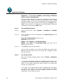
Getting Started
The SifoWorks U-series system supports Web-based administration,
enabling you to configure the system from different operating
systems simply through a standard web browser.
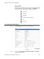
Logging into the System
Step 1:
Activate your preferred web browser (such as Internet Explorer,
Firefox etc.).
Step 2:
Enter the system’s IP address into the address bar.
You can use the HTTP (http://IP) or HTTPS (https://IP) protocols to
access the Web UI if enabled in the system’s interface configuration.
Please refer to section “3.2 Configuring the Physical Interfaces” for
details on enabling access through the required protocol. Note that
HTTPS is not supported by the SifoWorks U100 system.
2
Note: On your first login, you should connect to the device’s LAN
interface with default IP address 192.168.1.1. You can then proceed to
configure the system for administrator access via the other interfaces.
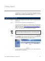
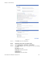
Step 3:
At the prompt, login with your administrator account username
and password. Upon successful login, you will be greeted with the
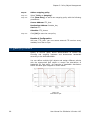
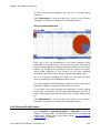
system’s web interface as shown in the figure below:
Figure 1
You can navigate the system functions via the menu displayed on
the left column of the interface.
User Manual for SifoWorks U-Series 4.05
17
Getting Started
Logging Out from the System
For security reasons, you should logout of the system after you
have completed your configuration operations. From the left menu,
select “System > Logout > Logout”. At the prompt, confirm that
you want to logout of the system.
You will need to restart your browser if you wish to re-login.
18
User Manual for SifoWorks U-Series 4.05
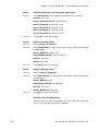
Chapter
1
Administrator Management
1.1 Administrator Accounts
SifoWorks U-series devices come with a default administrator
account with the username “admin” and password “admin”. This
account cannot be deleted from the system. For security purposes,
we recommend that you change the default password of this
account. Please refer to section “1.1.2 Changing an Account
Password” for information on changing account password.
The SifoWorks U-series default administrator account acts as a
main administrator with read-write authority. This means that this
administrator account is authorized to perform configurations on
the system.
You can add multiple administrator accounts. There are two types
of administrators in the system. Sub-administrators are assigned
with a read authority. Hence, these administrators are only
authorized to view the system settings and access the “Monitor”
function. Main administrators are authorized to access all functions
in the system.
Note: SifoWorks U100 assigns read-write access to the default
administrator only. All other administrators added can only be assigned
with read authority (sub administrators).
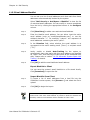
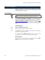
From the left menu bar, select “System > Administration >
Admin” to view the list of administrators. You can edit or delete an
account by clicking the [Modify] or [Remove] button
corresponding to an administrator account in the list respectively.
User Manual for SifoWorks U-Series 4.05
19
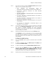
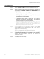
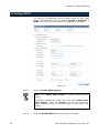
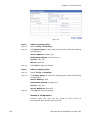
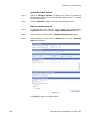
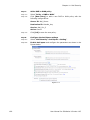
Chapter 2: Basic System Configurations
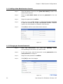
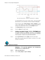
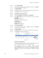
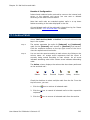
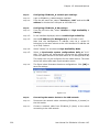
1.1.1 Adding a New Administrator Account
Step 1:
From the bottom of the list, click [New Sub Admin] to add a new
administrator account.
Step 2:
Enter the sub admin name and account password in the next
screen.
Step 3:
Retype the password to confirm.
Step 4:
Enable the options write access and view log & report privilege
to add the account as a main administrator account. These 2
options are not available for SifoWorks U100 devices.
Step 5:
Click [OK] to add the new administrator account.
Figure 1.1
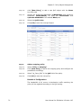
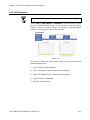
1.1.2 Changing an Account Password
Step 1:
From the administrator list, click the
corresponding to the account you want to edit.
[Modify]
button
Step 2:
In the next screen, enter the account’s current password and the
new password to change to.
Step 3:
Retype the new password to confirm.
Step 4:
Click [OK] to save the changes.
Figure 1.2
20
User Manual for SifoWorks U-Series 4.05
Chapter 2: Basic System Configurations
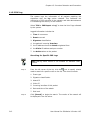
1.2 Permitted Login IPs
SifoWorks U-series allows the main administrator to restrict the IP
addresses from which administrators can log into the system.
Select “System > Administration > Permitted IPs” to view the
list of permitted IP addresses. You can edit or delete permitted IP
addresses by clicking the appropriate [Modify] or [Remove]
buttons respectively.
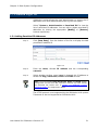
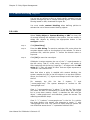
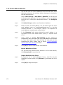
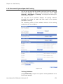
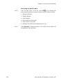
1.2.1 Adding Permitted IP Addresses
Step 1:
Click [New Entry] from the bottom of the list to display the Add
permitted IP address UI.
Figure 1.3
Step 2:
Enter the name, allowed IP address and the corresponding
netmask.
Step 3:
Select whether to allow users logged in through this IP address to
access the Ping/Traceroute, HTTP and HTTPS services.
Note: You must disable Ping/Traceroute, HTTP and HTTPS system
management services from the “Interface” function only after setting
the Permitted IPs. Please refer to section “3.1 SifoWorks U-series
Operating Modes” for configuration details.
The HTTPS protocol is not supported by the SifoWorks U100 system.
Traceroute is also not supported on SifoWorks U100.
User Manual for SifoWorks U-Series 4.05
21
2
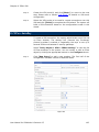
Chapter
Basic System Configurations
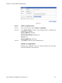
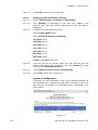
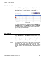
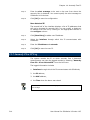
2.1 Basic Settings
Select “System > Configure > Setting” from the left menu. Here,
the main administrator can set up a number of basic system
settings described in the following sections.
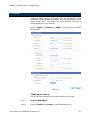
2.1.1 Importing/Exporting System Settings
Export System Settings
Click the [Download] button to export the current configurations
into a file to be stored in the local disk.
Import System Settings
In the “SifoWorks Configuration” portion on the top of the page,
you can import a previously saved configuration file into the system.
Click [Browse…] to select the file to import and click [OK] from
the bottom of the page.
Note: The system will be automatically rebooted after importing the
configuration file. A warning message will be displayed and users will
be able to re-login to the system in about 2 minutes.
Reset to Factory Default Setting
Select Reset system to factory setting and click [OK] from the
bottom of the page to reset all system configurations to the default
factory setting.
User Manual for SifoWorks U-Series 4.05
23
Chapter 2: Basic System Configurations
Format Device Hard Disk
Select Format Hard Disk and click [OK] from the bottom of the
page to format the SifoWorks U-series’ hard disk.
Note: SifoWorks U100 is not equipped with an in-built hard disk.
Hence, this configuration option is not available for SifoWorks U100
systems.
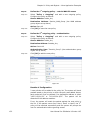
2.1.2 Email Alert Notification Settings
This function enables the system to send email alerts informing
administrators of detected attacks or network emergency conditions.
Step 1:
In the “System Name Setting” portion, enter your company name
and the device name used to identify this SifoWorks U-series
device. For SifoWorks U100 devices, only the device name can be
configured.
Step 2:
In the “E-mail Setting” portion, select enable E-mail alert
notification.
Step 3:
Configure the corresponding parameters including the sender
address, SMTP server address and up to 2 recipient e-mail
addresses.
If you are using a SifoWorks U100 device, please skip steps 4 and 5
as these parameters are not available on the device.
Step 4:
If the system must be authenticated by the SMTP server, enable
SMTP server authentication.
Step 5:
Enter the username and password.
Step 6:
Click [Mail Test] to check that the configured recipients are able
to receive the alert notification emails.
Step 7:
Click [OK] from the bottom of the page to save the setting.
2.1.3 Reboot System
From the bottom of the page, click [Reboot] to restart the
SifoWorks U-series device.
24
User Manual for SifoWorks U-Series 4.05
Chapter 2: Basic System Configurations
2.1.4 DMZ Port Switch
Select whether to enable DMZ port switch to WAN port. You can
use the DMZ port as a WAN port when this is enabled. Note that
the system will reboot when you click [OK] to save this setting.
This option is not available on SifoWorks U100.
2.1.5 Basic Network Settings
Figure 2.1
“Web Management (WAN Interface)”
Here you can change the HTTP and HTTPS port numbers. Note
that when this is modified, the administrator must change his
browser’s port number accordingly when attempting to enter the
SifoWorks U-series WebUI (for example, http://192.168.1.1:8080).
You can also set the idle timeout for administrator logins.
Note: HTTPS Port and Idle timeout parameters are not available for
SifoWorks U100.
User Manual for SifoWorks U-Series 4.05
25
Chapter 2: Basic System Configurations
“MTU Setting”
You can edit the maximum size of a network packet here.
“Scanned HTTP/FTP Setting”
Specify the size of HTTP/FTP files that are scanned by the system.
This parameter is not available for configuration on SifoWorks U100.
“Link Speed/Duplex Mode Setting”
Select the link speed and the duplex mode (full/half) for each of the
WAN interfaces.
“Dynamic Routing (RIPv2)”
Step 1:
Select the ports to enable dynamic routing on. With this enabled,
the system will route packets based on the RIP protocol.
Step 2:
Set the routing information update timer and timeout.
“SIP/H.323 Protocol pass-through”
Select whether to enable SIP (Session initiation protocol) passthrough and/or H.323 protocol pass-through. If enabled, all
SIP/H.323 packets will be processed before forwarded to their
respective destinations. Note that only SIP protocol pass-through is
supported on SifoWorks U100.
“Administration Packet Logging”
Select whether to enable logging of administration packets. When
this is enabled, SifoWorks U-series will record all packets with
SifoWorks U-series’ IP address as the source or destination IP
address. This record can be viewed by selecting “Monitor > Log >
Event” from the left menu. Please refer to section “16.1 Logs” for
more information.
2
Click [OK] from the bottom of the page to save the configurations.
2.1.6 List Display Per Page
From the bottom of the “System > Configure > Setting”
interface, you can select the number of entries to be displayed per
page of a list on the interface. Click [OK] from the bottom of the
page to save the setting.
This parameter is not available on SifoWorks U100.
26
User Manual for SifoWorks U-Series 4.05
Chapter 2: Basic System Configurations
2.2 System Date and Time Settings
From the left menu, select “System > Configure > Date/Time”
to set up the device’s date and time. You can choose to synchronize
the device’s clock with either an Internet Time Server or the
administrator’s system clock.
Synchronize system clock with an Internet Time Server
Select to synchronize system clock with an Internet time
Server and set up the parameters accordingly including:
•
GMT offset. Click the [Assist] link to view a list of countries
and their respective GMT offset value.
•
If daylight saving is enforced, select to enable daylight saving
and specify the dates during which daylight saving is in effect.
•
IP address of the time server. Click the [Assist] link to view a
list of available time servers and their IP addresses.
•
Time interval for updating the system clock.
Click [OK] to save the changes.
Synchronize device’s
system clock
clock
with
administrator
PC’s
Click the [Sync] button next to Synchronize system clock with
this client to synchronize SifoWorks U-series’ clock with the
system clock of the administrator’s PC.
User Manual for SifoWorks U-Series 4.05
27
Chapter 2: Basic System Configurations
2.3 Language Settings
Step 1:
Select “System > Configure > Language” from the left menu.
The SifoWorks U-series system can be displayed in 1 of 3
languages including English, Simplified Chinese and Traditional
Chinese.
Step 2:
Select your desired language.
Step 3:
Click [OK] to change the UI display to the selected language.
2.4 Software Update
You can update the system’s software using the appropriate update
files here.
Step 1:
Select “System > Administration > Software Update”.
Step 2:
Click [Browse…] and select the upgrade file.
Step 3:
Click [OK] to begin the update.
Note: The update process takes roughly 3 minutes. The system will be
automatically rebooted after the update is completed.
We strongly recommend that you do not turn off the PC or leave the
WebUI during this period as it may result in unexpected system errors.
28
User Manual for SifoWorks U-Series 4.05
Chapter 2: Basic System Configurations
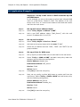
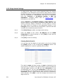
2.5 SNMP
Using the SNMP function, the system can be configured to send
notifications to the specified recipients when system events such as
attack alerts occur. This keeps the administrators informed of
events happening in the network.
Select “System > Configure > SNMP” to view the current SNMP
configuration.
Figure 2.2
“SNMP Agent Setting”
Set up the basic settings of the SNMP function in this area.
Step 1:
Enable SNMP Agent.
Step 2:
Enter the name and location of this SifoWorks device.
User Manual for SifoWorks U-Series 4.05
29
Chapter 2: Basic System Configurations
Step 3:
Configure the remaining parameters.
Step 4:
To use SNMP version 3, select enable SNMPv3.
Step 5:
Select the security level and enter the user name, auth
protocol and password and privacy protocol and password if
the required.
Note: The parameters privacy protocol and privacy password
are not available on SifoWorks U100.
Step 6:
Click [OK] to save the settings.
“SNMP Trap Setting”
Step 1:
Select to enable SNMP Trap alert notification. The system will
send alert events to the trap recipient specified here.
Step 2:
Specify the receiver address and the trap port.
Step 3:
Click [OK] to save the configuration.
You can also click [Trap Test] to test that the SNMP trap is
working correctly.
30
User Manual for SifoWorks U-Series 4.05
Chapter
3
Network Settings
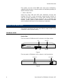
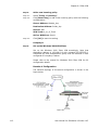
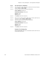
3.1 SifoWorks U-series Operating Modes
You can configure the SifoWorks U-series device to operate in one
of 2 working modes, routing mode, and mix mode.
3.1.1 Routing Mode
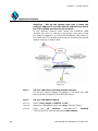
Figure 3.1
In routing mode, SifoWorks LAN, WAN and DMZ ports are
connected to different network segments. Data is transmitted via
NAT or route forwarding from the Intranet to the Internet and from
DMZ to the Internet.
User Manual for SifoWorks U-Series 4.05
31
Chapter 3: Network Settings
This mode is suitable for the following network environments:
1. Internal users are assigned private IP addresses. Therefore, the
system needs to translate these addresses to a public IP
address via NAT when users access the Internet.
2. A server providing services to the external network but is not
assigned a public IP address or there is insufficient public IP
address for use. Hence, the address needs to be translated, via
NAT, to the SifoWorks WAN port address or an IP address in the
same segment as the WAN port address.
3. An internal server providing services to the external network is
assigned a public IP address but administrators want to hide
this IP address.
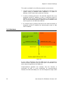
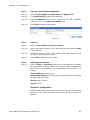
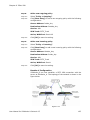
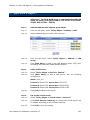
3.1.2 Mix Mode
Figure 3.2
In mix mode, SifoWorks LAN and WAN ports are connected to
different network segments while the DMZ port is connected to the
same network segment as the WAN port.
Communications between the Intranet and the Internet is
performed via NAT or route forwarding. All communications
between the DMZ and WAN port is via the transparent bridge mode.
32
User Manual for SifoWorks U-Series 4.05
Chapter 3: Network Settings
This mode is suitable for the following network environments:
1. User’s internal address is a private IP address and needs to be
translated to a public IP address via NAT when accessing the
Internet.
2. The server must be able to provide services to be accessed
externally. Since there are sufficient public IP addresses to be
assigned to the server, the servers located within the DMZ zone
must therefore be configured with a public IP address.
3.2 Configuring the Physical Interfaces
3.2.1 LAN Interface
Step 1:
Select “Interface > LAN” to configure the LAN interface port.
Step 2:
Enter the IP address, netmask and MAC Address of the
connected LAN.
Step 3:
Enabling Ping/Traceroute will allow users on the connected LAN
to execute ping and traceroute commands on this interface’s
address. Note that SifoWorks U100 does not provide the
“traceroute” function.
Step 4:
Enable HTTP and/or HTTPS to allow administrators to login to the
device’s WebUI from the connected LAN via the HTTP and/or HTTPS
protocol.
HTTPS is not supported by the SifoWorks U100 system.
Step 5:
Click [OK] to save the configurations. Please restart the system for
the new LAN IP address to take effect.
3.2.2 WAN Interface
Step 1:
Select “Interface > WAN” to configure the WAN interface ports.
The list shows the current configurations for the WAN ports. Note
that the “WAN1” port cannot be disabled while the remaining WAN
ports are disabled by default.
Figure 3.3
User Manual for SifoWorks U-Series 4.05
33
Chapter 3: Network Settings
Step 2:
From the top of the list, select the balance mode between the two
WAN ports. The available modes include:
•
Auto:
SifoWorks
will
automatically
adjust
the
downstream/upstream bandwidth between the two WAN ports.
•
Round-Robin: SifoWorks
bandwidth in order.
•
By Traffic: Bandwidth is distributed based on the accumulative
traffic on each port.
•
By Session: Bandwidth is distributed based on the number of
connections on each port.
•
By Packet: Bandwidth is distributed based on the number of
packets and connections on each port
•
By Source IP: Bandwidth is distributed based on the source IP
of the packets.
•
By Destination IP: Bandwidth is distributed based on the
destination IP of the packets.
distributes
the
WAN
download
Step 3:
You can also select the maximum number of sessions on each WAN
port from the Saturated Connections column of the list. When
this number is reached, SifoWorks will direct subsequent
connections to the next port. Note that this is not configurable if
only one WAN port is enabled.
Step 4:
Set the port’s Internet access priority from the Priority column.
Click [Modify] to edit the configuration of the corresponding WAN
port. Note that the settings for all WAN ports are similar except
that WAN interfaces other than WAN1 have the additional option of
being disabled.
Configure the WAN Interface
34
Step 5:
Set up the service used to perform connection tests on the WAN
interface.
Step 5.1:
If “DNS” is selected, enter the DNS Server IP address and
corresponding Domain name.
Step 5.2:
If “ICMP” is selected, enter the Alive Indicator Site IP address.
Step 5.3:
You can click the [Assist] link next to the DNS Server IP
Address, Domain name or Alive Indicator Site IP to view a list
of the available DNS Server IP addresses/DNS Server Domain
Name/Alive Indicator Site IP addresses respectively.
Step 6:
Specify the time interval between the sending of each alive packet.
User Manual for SifoWorks U-Series 4.05
Chapter 3: Network Settings
Step 7:
Select the Internet connection mode from the three methods
available, including:
1. “PPPoE”
This refers to ADSL modem connections. The configuration interface
is shown below:
Figure 3.4
Step 7.1.1:
Current Status: The current connection status. You can click the
[Connect] or [Disconnect] button to connect or disconnect the
connection respectively.
Step 7.1.2:
IP Address: Displays the IP address of the connection.
Step 7.1.3:
Enter the user name and password as registered with the
Internet service provider (ISP).
Step 7.1.4:
Specify whether a fixed or dynamic connection IP address is
obtained from the ISP.
Step 7.1.5:
If the IP address obtained by the ISP is fixed, enter the IP
address, netmask and default gateway of the connection.
Step 7.1.6:
Configure the maximum downstream and upstream bandwidth
of the connection and set the idle time.
User Manual for SifoWorks U-Series 4.05
35
Chapter 3: Network Settings
2. “Dynamic IP Address”
This is for cable modem connections. The configuration interface is
shown below:
Figure 3.5
36
Step 7.2.1:
IP Address displays the IP address currently assigned to this
connection by the ISP.
Step 7.2.2:
Click [Renew] to obtain an IP address from the ISP. Click
[Release] to stop the use of this IP address and disconnect from
the ISP.
Step 7.2.3:
If required by the ISP, click [Clone MAC
automatically configure the system’s MAC address.
Step 7.2.4:
Enter the hostname, domain name, user name and password
as provided by the ISP.
Step 7.2.5:
Specify the maximum downstream and upstream bandwidth of
this connection.
Address]
to
User Manual for SifoWorks U-Series 4.05
Chapter 3: Network Settings
3. “Static IP Address”
This is for users on static connections or ADSL static line users.
Figure 3.6
Step 7.3.1:
Here, enter the static IP address, netmask, MAC address, the IP
address of the default gateway and the DNS servers.
Note that IP addresses of the DNS servers can only be configured
for the WAN1 interface.
Step 7.3.2:
Specify the maximum downstream and upstream bandwidth
for this connection.
Step 8:
From the bottom of the configuration interface, enable HTTP
and/or HTTPS to allow administrators to login to the device’s
WebUI from the connected WAN. HTTPS is not supported by the
SifoWorks U100 system.
Step 9:
Enabling Ping/Traceroute will allow users on the connected WAN
to execute ping and traceroute commands on this interface’s
address. Note that SifoWorks U100 does not provide the
“traceroute” function.
Step 10:
Click [OK] to save the configurations.
Warning: Allowing WAN users to access the system’s WebUI may
compromise the security of the system and network. We therefore
recommend that you disable HTTP, HTTPS and PING/Traceroute on
the WAN interfaces.
If the administrator needs to access the WebUI from the WAN network,
we recommend that you set up permitted IPs instead. Please refer to
section “1.2 Permitted Login IPs” for configuration details.
User Manual for SifoWorks U-Series 4.05
37
Chapter 3: Network Settings
3.2.3 DMZ Interface
Step 1:
Select “Interface > DMZ” to configure the DMZ interface port.
Step 2:
Select the working mode from the drop down menu and enter the
corresponding IP address, netmask and MAC address. The
modes include:
Step 3:
•
“Disable”: Disable the use of the DMZ port.
•
“NAT”: In NAT mode, DMZ exists as an independent virtual
subnet. The virtual subnet must not be the same as the
configuration for the LAN interface.
•
“Transparent Routing”: When a packet from DMZ is sent to
SifoWorks, the packet will be forwarded to the appropriate
interface according to the system’s route table.
•
“Transparent Bridging”: When a packet from DMZ is sent to the
system, the system decides which interface to forward the
packet to according to its destination MAC address. In this mode,
SifoWorks operates as a basic network switch.
From the bottom of the configuration interface, enable HTTP
and/or HTTPS to allow administrators to login to the device’s
WebUI from the connected DMZ.
HTTPS is not supported by the SifoWorks U100 system.
38
Step 4:
Enabling Ping/Traceroute will allow users on the connected DMZ
to execute ping and traceroute commands on this interface’s
address. Note that SifoWorks U100 does not provide the
“traceroute” function.
Step 5:
Click [OK] to save the settings.
User Manual for SifoWorks U-Series 4.05
Chapter 3: Network Settings
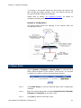
3.3 Configuring Multiple Subnets
From the left menu, select “System > Configure > Multiple
Subnets”. This function allows administrators to set up multiple
subnets within the LAN or DMZ network.
The list displayed shows the various subnets configured in the
system and their corresponding settings. You can edit or delete any
subnet from the list by clicking the appropriate buttons.
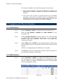
Step 1:
Click [New Entry] to add a new subnet.
Figure 3.7
Step 2:
Select the whether the subnet is in the “LAN” or “DMZ” interface.
Step 3:
Enter the Alias IP address of this subnet and the corresponding
netmask.
Step 4:
Set up the WAN Interface IP addresses of WAN1 and/or other
WAN ports that the subnet communicates with (if enabled). Click
the [Assist] link to view a list of the WAN IP addresses.
Step 5:
Select the Forwarding Mode for each WAN interface the subnet
communicates with. NAT mode allows multiple subnet addresses to
connect to the Internet through different WAN IP addresses.
Routing mode is similar to NAT mode except that the WAN IP
addresses need not be real addresses. Internal hosts access
external network via its own IP address.
Step 6:
Click [OK] to add the new subnet.
User Manual for SifoWorks U-Series 4.05
39
Chapter 3: Network Settings
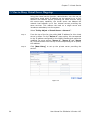
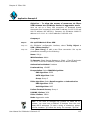
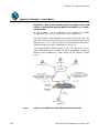
Application Example
Objective – To set up 2 subnets, each using a different
mode to link to the Internet
In this example, we set up 2 subnets such that both are able to
connect to the Internet through the SifoWorks U-series WAN
interfaces. WAN1 (10.10.10.1) is connected to an ISP router with IP
address 10.10.10.2 and connects to the Internet via routing mode.
WAN2 (211.22.22.22) is connected to the ADSL/Cable router and
connects to the Internet via NAT mode.
Step 1:
Set up Multiple Subnets
Step 1.1:
From the left menu, select “System > Configure > Multiple
Subnet”.
Step 1.2:
From the bottom of the list displayed, click [New Entry] and set
up as follows:
Alias IP of LAN Interface: 162.172.50.1
Netmask: 255.255.255.0
WAN1: Select Routing for Forwarding Mode
WAN2: Select NAT for Forwarding Mode and enter the IP
address 211.22.22.22.
Step 1.3:
Click [OK] to save the new subnet.
We now have 2 subnets in the LAN, the default LAN subnet with
address 192.168.1.0/24 and the subnet we configured earlier
162.172.50.0/24.
Step 2:
Set up the policies
Set up the relevant outgoing Policy rules in “Policy > Outgoing”
such that:
1. All hosts in the default subnet with IP address 192.168.1.xxx can
only access the Internet through the WAN2 interface via NAT mode.
Hosts in this subnet cannot use their private IP to access the
internet via routing mode.
2. All hosts in the second subnet with IP address 162.172.50.xxx
can access the Internet via routing mode through the WAN1
interface. In this mode, the host’s IP address (162.172.50.xxx) is
made public to the Internet servers.
40
User Manual for SifoWorks U-Series 4.05
Chapter 3: Network Settings
3. All hosts in the second subnet can also access the Internet via
NAT through the WAN2 interface. Here, the internet servers will
only see the WAN2 interface’s IP address.
Please refer to section “4.1 Outgoing Policies” for details on
configuring outgoing policies.
Results of Configuration
The figure below shows the topology of the network after the
configurations above.
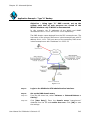
Figure 3.8
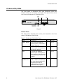
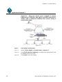
3.4 Route Table
Select “System > Configure > Route Table” to view the list of
static routes configured in the system. From the list, you can edit
or delete the routes by clicking the appropriate buttons.
Figure 3.9
Step 1:
Click [New Entry] to view the “add new static route” configuration
interface.
Step 2:
Enter the relevant parameters including Destination IP, Netmask,
Gateway and Interface of the static route.
Step 3:
Click [OK] to add the new static route.
User Manual for SifoWorks U-Series 4.05
41
Chapter 3: Network Settings
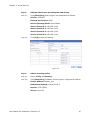
3.5 Setting DHCP
You can set up SifoWorks UTM as a DHCP server or DHCP relay
server to provide DHCP services. Select “System > Configure >
DHCP” from the left menu to view the configuration interface.
Figure 3.10
Step 1:
Select to Enable DHCP Support.
Note: Select Disable DHCP Support to disable SifoWorks’ DHCP
service.
To configure SifoWorks as a DHCP relay server, select Enable DHCP
Relay Support. Select the interface used for communications
between SifoWorks and the server and specify the DHCP server’s IP
address.
Step 2:
42
Enter the Domain Name where the server is situated.
User Manual for SifoWorks U-Series 4.05
Chapter 3: Network Settings
Step 3:
Enter the IP addresses of the primary and secondary DNS server
and WINS Server. You can also select to Automatically Get DNS
server’s IP address. The system will use the IP address of the LAN
interface as the address of the primary DNS server.
Step 4:
Specify the Client IP Range used for DHCP lease for the LAN
interface and the DMZ interface separately. You can define up to
2 IP ranges for each of the 2 interfaces.
Note that
1. IP addresses within a range must be in the same subnet.
2. Addresses in Client IP range 2 must be within the same
subnet as Range 1.
3. Client IP range 2 cannot contain the same IP addresses as
Client IP range 1.
Step 5:
Enter the lease time for each IP address lease. The default lease
time is 24 hours. Click [OK] to save the configurations.
3.6 Dynamic DNS
The dynamic DNS service translates specific domain names to the
corresponding host computer which IP address is not static. Users
can access the host using just the domain name without having to
know the dynamic IP address provided by the computer’s ISP.
From the left menu, select “System > Configure > Dynamic
DNS”. You can set up the use of dynamic DNS (DDNS) servers by
the system through this function.
Step 1:
Click [New Entry] to view the configuration interface as shown in
the figure below:
Figure 3.11
Step 2:
Select the Service Provider you are registered with. You can click
the [sign up] link to enter the service provider’s website to sign up
for the DDNS service.
Step 3:
Enter the WAN IP address or select to automatically fill in the IP
according to the address of WAN interface selected.
User Manual for SifoWorks U-Series 4.05
43
Chapter 3: Network Settings
Step 4:
Enter the registered user name, password, and the domain
name of the host.
Step 5:
Click [OK] to add the new dynamic DNS.
The icon in the leftmost column of the DDNS list displays the status
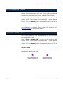
of the corresponding DDNS. The icons include:
Update
Successful
Incorrect username
or password
Connecting
to server
Unknown
error
3.7 Host Table
Select “System > Configure > Host Table” to view the list of
host name to virtual IP address mappings. Click [New Entry] to
set up mappings between virtual IP addresses and host names.
The virtual IP address must be the IP address of SifoWorks’ LAN or
DMZ interface.
Internal users will be able to access services on this host using the
virtual IP address mapped to it.
Note: The IP address of the user’s primary DNS server must be the
same as SifoWorks’ LAN port or DMZ Port IP address.
44
User Manual for SifoWorks U-Series 4.05
Chapter
4
Firewall Policy Management
The firewall policy management system is one of the core functions
of the SifoWorks U-series security gateway device. All data packets
in the network (other than VPN packets) are matched with the
policies defined in the system. A data packet is permitted as long as
it matches one policy with the permit action.
You can set up different policies based on the inbound and
outbound networks of the traffic. As policy objects are frequently
used to configure the policies, we recommend that you first add the
objects necessary. Please refer to chapter “5 Policy Object
Management” to chapter “8 IPsec VPN” for object configuration
details.
4.1 Outgoing Policies
Outgoing policies are used when the source IP is in the LAN
network while the destination is in the WAN network.
Select “Policy > Outgoing” to view the list of outgoing policies
defined in the system. You can modify or delete policies from the
list by clicking the appropriate buttons in the configure column.
Click the [Pause] button to temporarily pause the use of the
corresponding policy.
User Manual for SifoWorks U-Series 4.05
45
Chapter 4: Firewall Policy Management
Action Column
The Action column in the list displays the action performed on the
data packets matching the policy.
Permit packets on all WAN interfaces
Only permit packets on the WAN1 interface
Only permit outgoing packets on the other interface.
The number on the icon corresponds to the number of
the interface selected. For example, a “2” icon
indicates that packets on the WAN2 interface are
permitted.
Note that if the WAN interface is enabled, the icon
number displayed is yellow. If the interface is
disabled, it will be displayed in red. Please refer to
section “3.2.2 WAN Interface” for details on
configuring WAN interfaces.
Permit only outgoing packets through the selected
VPN trunk
Deny packets that matches the policy
Policy is disabled
Option Column
Administrators can enable various options such as enable traffic log,
content blocking etc. when defining policies. The Options column
in the list shows the options that are enabled for each policy.
Traffic Log
Statistics
Authentication User
Schedule
Content Blocking
QoS
IDP
Application Blocking
Anti-Virus
46
User Manual for SifoWorks U-Series 4.05
Chapter 4: Firewall Policy Management
4.1.1 Adding Outgoing Policies
Step 1:
Click [New Entry] to add a new outgoing policy.
Figure 4.1
Step 2:
Select the source address, destination address and service to
match to the data packets.
Step 3:
Select the Action, WAN Port to perform on packets matching this
policy.
Step 4:
Select whether to enable the various policy options including
1. Schedule: Select the schedule object to specify when the policy
will be in effect.
2. Authentication User: Select the user object required to be
authenticated when attempting to send outgoing packets that
matches this policy.
3. VPN Trunk: Select the VPN Trunk object that will be monitored
using this policy.
User Manual for SifoWorks U-Series 4.05
47
Chapter 4: Firewall Policy Management
4. Traffic Log: Select to log the packets that match this policy
into the traffic log.
5. Statistics: Select to collect the statistics generated by this
policy. Administrators can view the statistics in “Monitor >
Statistics > Policy”. Please refer to section “16.3.2 Policy
Statistics” for more details.
6. IDP: Select to enable IDP for packets matching this policy.
Please refer to chapter “13 Intrusion Detection and Prevention”
for details on configuring IDP.
7. Content Blocking: Select which content blocking objects to be
blocked by this policy.
8. Application Blocking: Select the application blocking object to
be activated in this policy.
9. Anti-Virus: Select whether to enable anti-virus checks on
HTTP/Webmail or FTP packets matching this policy. This option
is not available for SifoWorks U100.
10. QoS: Enable quality of service by selecting the appropriate QoS
object.
Step 5:
Using policies, you can also manage the maximum concurrent
sessions per IP and maximum upstream and downstream
bandwidth per source IP for the addresses matching this policy.
Step 6:
Also specify the total maximum concurrent sessions allowed.
Step 7:
Enter the quota per session and quota per day to manage the
bandwidth used by all packets matching this policy.
Note: Quota per session and Quota per
parameters are not available on SifoWorks U100
Step 8:
Enter a brief comment for this policy if desired.
Step 9:
Click [OK] to add the new outgoing policy.
day configuration
4.1.2 Adjusting Policies’ Positions
The SifoWorks system matches each packet with the policies in the
list in a top down fashion. The system will check from the first to
the last policy in the list until a match is found. Therefore, the
position of the policies is of utmost importance to the operation of
the firewall.
In the move column, select the position of the policy from the drop
down list to adjust the policies’ priority.
48
User Manual for SifoWorks U-Series 4.05
Chapter 4: Firewall Policy Management
4.2 Incoming Policies
Incoming policies are used when the source IP is in the WAN
network while the destination is in the LAN network.
Select “Policy > Incoming” to view the list of incoming policies
defined in the system. You can modify or delete policies from the
list by clicking the appropriate buttons in the configure column.
Click the [Pause] button to temporarily pause the use of the
corresponding policy.
Action Column
The Action column in the list displays the action performed on the
data packets matching the policy.
Permit packets on all WAN interfaces
Permit only incoming packets through the selected
VPN trunk
Deny packets that matches the policy
Policy is disabled
Option Column
Administrators can enable various options such as enable traffic log,
content blocking etc. when defining policies. The Options column
in the list shows the options that are enabled for each policy.
Traffic Log
Statistics
Schedule
Network Address Translation
QoS
IDP
User Manual for SifoWorks U-Series 4.05
49
Chapter 4: Firewall Policy Management
4.2.1 Adding Incoming Policies
Step 1:
Click [New Entry] to add a new incoming policy.
Figure 4.2
Step 2:
Select the Source Address, Destination Address and Service to
match to the data packets.
Step 3:
Select the Action to perform on packets matching this policy.
Step 4:
Select whether to enable the various policy options including
1. Schedule: Select the schedule object to specify when the policy
will be in effect.
2. VPN Trunk: Select the VPN Trunk object that will be monitored
using this policy.
3. Traffic Log: Select to log the packets that match this policy
into the traffic log.
4. Statistics: Select to collect the statistics generated by this
policy. Administrators can view the statistics in “Monitor >
Statistics > Policy”. Please refer to section “16.3.2 Policy
Statistics” for more details.
50
User Manual for SifoWorks U-Series 4.05
Chapter 4: Firewall Policy Management
5. IDP: Select to enable IDP for packets matching this policy.
Please refer to chapter “13 Intrusion Detection and Prevention”
for details on configuring IDP.
6. QoS: Enable quality of service by selecting the appropriate QoS
object.
7. NAT: Select to enable network address translation
Step 5:
Using policies, you can also manage the Max. Concurrent
Sessions Per IP and Max. Upstream and Downstream
Bandwidth Per Source IP for the addresses matching this policy.
Step 6:
Also specify the total Max. Concurrent Sessions allowed.
Step 7:
Enter the Quota Per Session and Quota Per Day to manage the
bandwidth used through the policy.
Note: Quota per session and Quota per
parameters are not available on SifoWorks U100
Step 8:
Enter a brief comment for this policy if desired.
Step 9:
Click [OK] to add the new incoming policy.
day configuration
4.2.2 Adjusting Policies’ Positions
The SifoWorks system matches each packet with the policies in the
list in a top down fashion. The system will check from the first to
the last policy in the list until a match is found. Therefore, the
position of the policies is of utmost importance to the operation of
the firewall.
In the move column, select the position of the policy from the drop
down list to adjust the policies’ priority.
User Manual for SifoWorks U-Series 4.05
51
Chapter 4: Firewall Policy Management
4.3 WAN to DMZ Policies
WAN to DMZ policies are used when the source IP is in the WAN
network while the destination is in DMZ. This is used when external
users access configured virtual service, mapped IP services etc.
Select “Policy > WAN to DMZ” to view the list of WAN to DMZ
policies defined in the system. You can modify or delete policies
from the list by clicking the appropriate buttons in the configure
column. Click the [Pause] button to temporarily pause the use of
the corresponding policy.
The configuration procedure for WAN to DMZ policies is identical to
the configuration for incoming policies. Please refer to section “4.2
Incoming Policies” for configuration details.
4.4 LAN to DMZ Policies
LAN to DMZ policies are used when the source IP is in LAN while
the destination is in DMZ.
Select “Policy > LAN to DMZ” to view the list of LAN to DMZ
policies defined in the system. You can modify or delete policies
from the list by clicking the appropriate buttons in the configure
column. Click the [Pause] button to temporarily pause the use of
the corresponding policy.
Action Column
The Action column in the list displays the action performed on the
data packets matching the policy.
Permit packets on all
network interfaces
52
Deny packets that
matches the policy
User Manual for SifoWorks U-Series 4.05
Chapter 4: Firewall Policy Management
Option Column
Administrators can enable various options such as enable traffic log,
content blocking etc. when defining policies. The Options column
in the list shows the options that are enabled for each policy.
Traffic Log
Statistics
Schedule
Network Address Translation
IDP
Anti-Virus
4.4.1 Adding LAN to DMZ Policies
Step 1:
Click [New Entry] to add a new LAN to DMZ policy.
Figure 4.3
Step 2:
Select the source address, destination address and service to
match to the data packets.
User Manual for SifoWorks U-Series 4.05
53
Chapter 4: Firewall Policy Management
Step 3:
Select the Action to perform on packets matching this policy.
Step 4:
Select whether to enable the various policy options including
1. Schedule: Select the schedule object to specify when the policy
will be in effect.
2. Traffic Log: Select to log the packets that match this policy
into the traffic log.
3. Statistics: Select to collect the statistics generated by this
policy. Administrators can view the statistics in “Monitor >
Statistics > Policy”. Please refer to section “16.3.2 Policy
Statistics” for more details.
4. IDP: Select to enable IDP for packets matching this policy.
Please refer to chapter “13 Intrusion Detection and Prevention”
for details on configuring IDP.
5. Anti-Virus: Select whether to enable anti-virus checks on
HTTP/Webmail or FTP packets matching this policy. This option
is not available for SifoWorks U100.
6. NAT: Select to enable network address translation
Step 5:
Using policies, you can also manage the maximum concurrent
sessions per IP for the addresses matching this policy.
Step 6:
Also specify the total maximum concurrent sessions allowed.
Step 7:
Enter the quota per session and quota per day to manage the
bandwidth used through the policy.
Note: Quota per session and Quota per
parameters are not available on SifoWorks U100
Step 8:
Enter a brief comment for this policy if desired.
Step 9:
Click [OK] to add the new incoming policy.
day configuration
4.4.2 Adjusting Policies’ Positions
The SifoWorks system matches each packet with the policies in the
list in a top down fashion. The system will check from the first to
the last policy in the list until a match is found. Therefore, the
position of the policies is of utmost importance to the operation of
the firewall.
In the move column, select the position of the policy from the drop
down list to adjust the policies’ priority.
54
User Manual for SifoWorks U-Series 4.05
Chapter 4: Firewall Policy Management
4.5 DMZ to WAN Policies
DMZ to WAN policies are used when the source IP is in the DMZ
network while the destination is in WAN.
Select “Policy > DMZ to WAN” to view the list of DMZ to WAN
policies defined in the system. You can modify or delete policies
from the list by clicking the appropriate buttons in the Configure
column. Click the [Pause] button to temporarily pause the use of
the corresponding policy.
The configuration procedure for DMZ to WAN policies is identical to
the configuration for outgoing policies. Please refer to section “4.1
Outgoing Policies” for configuration details.
4.6 DMZ to LAN Policies
DMZ to LAN policies are used when the source IP is in the DMZ
network while the destination is in LAN.
Select “Policy > DMZ to LAN” to view the list of DMZ to LAN
policies defined in the system. You can modify or delete policies
from the list by clicking the appropriate buttons in the Configure
column. Click the [Pause] button to temporarily pause the use of
the corresponding policy.
The configuration procedure for DMZ to LAN policies is identical to
the configuration for LAN to DMZ policies. Please refer to section
“4.4 LAN to DMZ Policies” for configuration details.
User Manual for SifoWorks U-Series 4.05
55
Chapter 4: Firewall Policy Management
4.7 Application Examples
Here we list a number of examples for the application of firewall
policies.
4.7.1 Monitoring the Activities of Internal Users
Here we set up a policy to monitor the network activities of internal
users. Select “Policy > Outgoing”.
Step 1:
Click [New Entry] to add a new outgoing policy. Configure the
policy as follows:
Step 2:
Source Address: Inside_Any
Step 3:
Destination Address: Outside_Any
Step 4:
Action: Permit All
Step 5:
Select to enable Traffic Log and Statistics.
Step 6:
Click [OK] to add the new policy.
Results of Configuration
The system will now record all outgoing activities from LAN users.
Administrators can view this log by selecting “Monitor > Log >
Traffic” from the menu.
Select “Monitor > Statistics > Policy” to view the statistics
generated by the policy.
56
User Manual for SifoWorks U-Series 4.05
Chapter
5
Policy Object Management
In the SifoWorks U-series system, objects refer to the various
components that make up the system's rules. These include
addresses, services as well as address groups and service groups,
but exclude the type of actions (such as permission, prohibition,
forwarding, etc.) specified by rules. An object definition consists of
a name, which is a character string arbitrarily defined by the
administrator when it is created; and its entity, which might be the
IP Address, the group of IP Address, service or service group
associated with the defined object.
Defining an object associates a name that is easier to remember to
an entity or a group of entities.
This way, not only are
administrators relieved from remembering all the components, the
process of making rules is also simplified and more intuitive since
security policies can now be managed in an object oriented
perspective.
After objects are defined, you can use them directly in subsequent
rule-making process when defining policies and VPN.
The use of objects allows different pieces of information to be
linked together by a specific object relationship. The linked
information can then be easily managed by referring to a single
object. This concept is useful in a network environment where there
are a large number of IP addresses, different logic working groups,
and different network services. For example, you can define the IP
Address groups of a logic team as a single object even if the groups
are located in different network segments. This way, you can
directly refer to an address object when defining a rule, instead of
entering multiple IP addresses. Also, when the members of the
logic team change, you can modify the object definition rather than
modify the SifoWorks system's policy rules.
This chapter introduces the various objects available in the
SifoWorks system.
User Manual for SifoWorks U-Series 4.05
57
Chapter 5: Policy Object Management
5.1 Address Objects
The use of address objects allows administrators to associate a
name to IP addresses. These can be the address of a host in the
network or the address of a sub network. Depending on the
network it belongs to, you can define a single LAN IP address, WAN
IP address or a DMZ IP address object.
To further simplify the policy making process, the system also
allows the definition of address groups for each of the 3 networks.
Address groups allow you to group multiple single IP address
objects into 1 group object. Therefore, you must first define the
necessary single address objects before defining address groups.
5.1.1 Single Address Objects
LAN Address Objects
From the left menu, select “Policy Object > Address > LAN” to
view the list of address objects for the LAN network. You can
modify or delete the objects by clicking the appropriate button in
the Configure column on the list. Note that the default address
object Inside_Any cannot be edited or deleted.
Step 1:
Click [New Entry] to add a new LAN address object.
Step 2:
In the “Add New Address” interface, enter the Name of the object,
IP Address and corresponding Netmask.
Step 3:
You can also enter a specific MAC Address to be mapped to the IP
address.
Step 4:
You can also select whether to get a static IP address from the
DHCP server.
Tip: Click [Clone MAC Address] for the system to automatically obtain
the current user PC’s MAC address.
Step 5:
58
Click [OK] to add the new address object.
User Manual for SifoWorks U-Series 4.05
Chapter 5: Policy Object Management
WAN Address Objects
From the left menu, select “Policy Object > Address > WAN” to
view the list of address objects for the WAN network. You can
modify or delete the objects by clicking the appropriate button in
the Configure column on the list. Note that the default address
object Outside_Any cannot be edited or deleted.
Step 1:
Click [New Entry] to add a new WAN address object.
Step 2:
In the “Add New Address” interface, enter the Name of the object,
IP Address and corresponding Netmask.
Step 3:
Click [OK] to add the new address object.
DMZ Address Objects
From the left menu, select “Policy Object > Address > DMZ” to
view the list of address objects for the LAN network. You can
modify or delete the objects by clicking the appropriate button in
the Configure column on the list. Note that the default address
object DMZ_Any cannot be edited or deleted.
Step 1:
Click [New Entry] to add a new DMZ address object.
Step 2:
In the “Add New Address” interface, enter the Name of the object,
IP Address and corresponding Netmask.
Step 3:
You can also enter a specific MAC Address.
Step 4:
You can also select whether to get a static IP address from the
DHCP server.
Step 5:
Click [OK] to add the new address object.
Tip: From the LAN and DMZ address objects list, clicking the [Assist
add] link from the top of the list will display all LAN/DMZ addresses
connected to SifoWorks. You can select the desired LAN/DMZ address
from this list to automatically add it as an address object in the system.
Note that this function is not available in SifoWorks U100.
User Manual for SifoWorks U-Series 4.05
59
Chapter 5: Policy Object Management
5.1.2 Address Group Objects
From the left menu, select “Policy Object > Address > LAN
Group” to view the list of address group objects for the LAN
network. You can edit or delete any object from the list by clicking
on the appropriate buttons in the Configure column.
Step 1:
Click [New Entry] to add a new address group object.
Step 2:
Enter the object’s name.
Step 3:
Select the addresses to add into the group from the left <--Available address ---> list and click the [Add >>] button to add
it into the <--- Selected address ---> list on the right. Available
addresses include all single LAN address objects in the system.
Address objects in the selected address list are members of this
address group.
Step 4:
Select the addresses from the list on the right and click
[<<Remove] to remove the selected addresses from the group.
Step 5:
Click [OK] to add the new address group.
This configuration interface is similar for all three types of groups
(LAN Group, WAN Group, and DMZ Group).
Application Example 1
Objective – To limit a user, assigned with a static IP
address by the DHCP server, to access only FTP resources
Step 1:
Add a new LAN address object (user)
Step 1.1
From the left menu, select “Policy Object > Address > LAN”.
Step 1.2
Click [New Entry] to add a new LAN address object. Configure the
parameters as follows:
Name: Rayearth
IP Address: 192.168.3.2
Netmask: 255.255.255.255
Mac Address: 00:B0:18:25:F5:89
60
Step 1.3
Select Get Static IP address from DHCP Server.
Step 1.4
Click [OK] to save the address object.
User Manual for SifoWorks U-Series 4.05
Chapter 5: Policy Object Management
Figure 5.1
Step 2:
Add an outgoing policy
Step 2.1
From the left menu, select “Policy > Outgoing”.
Step 2.2
Click [New Entry] to add a new outgoing policy. Configure the
parameters as follows:
Source Address: Rayearth
Destination Address: Outside_Any
Service: FTP
Action, WAN Port: Permit All
Step 2.3
Click [OK] to save the new outgoing policy.
Results of Configuration
Internal user “Rayearth” can now access external FTP resources
through SifoWorks U-series policy.
User Manual for SifoWorks U-Series 4.05
61
Chapter 5: Policy Object Management
Application Example 2
Objective – To allow a group of internal users to connect
to a specific external static IP address (202.1.237.21/32)
Step 1:
Add several LAN address objects (users)
Step 1.1
From the left menu, select “Policy Object > Address > LAN”.
Step 1.2
Click [New Entry] to add a new LAN address object and configure
the parameters accordingly.
Step 1.3
Click [OK] to save the address object.
Step 1.4
Repeat steps 1.1 to 1.3 to add other users.
Figure 5.2
Step 2:
Add a LAN address Group (user group)
Step 2.1
From the left menu, select “Policy Object > Address > LAN
Group”.
Step 2.2
Click [New Entry] to add a new group with name “Lan_Users”.
Step 2.3
From the <--- Available address ---> list on the left, select the
users added in step 1 and click [Add>>] to add the users as
members of this group.
Step 2.4
Click [OK] to save the new LAN group.
Step 3:
Add a WAN address object (remote site)
Step 3.1
From the left menu, select “Policy Object > Address > WAN”.
Step 3.2
Click [New Entry] to add a new LAN address object and configure
the parameters as follows:
Name: Yahoo
IP Address: 202.1.237.21
Netmask: 255.255.255.255
62
User Manual for SifoWorks U-Series 4.05
Chapter 5: Policy Object Management
Step 3.3
Click [OK] to save the address object.
Figure 5.3
Step 4:
Add an outgoing policy
Step 4.1
From the left menu, select “Policy > Outgoing”.
Step 4.2
Click [New Entry] to add a new outgoing policy and configure the
parameters as follows:
Source Address: Lan_Users
Destination Address: Yahoo
Service: ANY
Action, WAN Port: Permit All
Step 4.3
Click [OK] to save the new policy.
Results of Configuration
Internal users who are members of the group “Lan_Users” can now
access the remote IP address at 202.1.237.21.
5.2 Service Objects
Service embedded objects are defined by TCP, UDP services
provided in the network.
5.2.1 System Pre-defined Service Objects
SifoWorks U-series’ system predefines a number of commonly used
TCP and UDP services such as DNS, HTTP, and LDAP etc. These
services cannot be modified or deleted.
Select “Policy Object > Service > Pre-defined” to view the
details of the pre-defined services which includes the protocol type
and port number of the service.
User Manual for SifoWorks U-Series 4.05
63
Chapter 5: Policy Object Management
5.2.2 Custom Service Objects
In addition to pre-defined services, administrators can also define
customized services to suit their needs. Select “Policy Object >
Service > Custom” to view the list of user-defined service objects.
Step 1:
Click [New Entry] to add a new service object. Note that for
custom services, both the client and server port numbers ranges
from 0 to 65535.
Figure 5.4
Step 2:
Enter the Service NAME.
Step 3:
Select whether the service uses the “TCP” protocol, “UDP” protocol
or select “Other” and specify the protocol number.
Step 4:
Enter the Client and Server Port number range for the selected
protocol. Each service object can use up to 8 different Protocols,
each configured with a different client and server port number
ranges.
Step 5:
Click [OK] to add the new service object.
5.2.3 Service Group Objects
From the left menu, select “Policy Object > Service > Group” to
view the list of service group objects. You can edit or delete any
object from the list by clicking on the appropriate buttons in the
Configure column.
64
Step 1:
Click [New Entry] to add a new service group object.
Step 2:
Enter the object’s Name.
Step 3:
Select the services to add into the group from the left <--Available service ---> list and click the [Add >>] button to add
User Manual for SifoWorks U-Series 4.05
Chapter 5: Policy Object Management
it into the <--- Selected service ---> list on the right. The
available service list displays all pre-defined and custom services
currently in the system. All services that are members of this group
will be displayed in the selected service list.
Step 4:
Select the services from the list on the right and click [<<Remove]
to remove the selected services from the group.
Step 5:
Click [OK] to add the new service group.
Application Example
Objective – To allow LAN users access to a group of
services (HTTP, POP3, SMTP)
Step 1:
Add a new service group
Step 1.1
From the left menu, select “Policy Object > Service > Group”.
Step 1.2
Click [New Entry]
“Web_Mail_Svc”
Step 1.3
Select the services “HTTP”, “POP3” and “SMTP” from the <--Available Service---> list and click [Add>>] to add them as
members of this group.
Step 1.4
Click [OK] to save the service group.
to add a new service with the name
Figure 5.5
User Manual for SifoWorks U-Series 4.05
65
Chapter 5: Policy Object Management
Step 2:
Add the LAN address objects
Select “Policy Object > Address > LAN” and add the LAN users
accordingly.
Step 3:
Add a new LAN address group
Select “Policy Object > Address > LAN Group” and add a new
LAN address group “Lan_Webmail_Users” with the LAN users
configured in step 2 selected as members of this group.
Step 4:
Add a new outgoing policy
Step 4.1
From the left menu, select “Policy > Outgoing”.
Step 4.2
Click [New Entry] to add a new outgoing policy with the following
parameters:
Name: Web_Mail_Access
Source Address: Lan_Webmail_Users
Destination Address: Outside_Any
Service: Web_Mail_Svc
Action, WAN Port: Permit All
Step 4.3
Click [OK] to save the new policy.
Results of Configuration
Internal
users
who
are
members
of
the
group
“Lan_Webmail_Users” can now access all external services in the
group “Web_Mail_Svc”.
5.3 Schedule Objects
You can define schedule objects to set up schedules when specific
policies are in effect. From the menu, select “Policy Object >
Schedule > Setting” to view a list of schedules.
Step 1:
Click [New Entry] to add a new schedule.
Step 2:
Enter the Schedule Name and specify the time period for each
day of the week the schedule is set to take effect.
Step 3:
Click [OK] to save the new schedule.
Note that schedule objects will only take effect when used in policy
definitions. Please refer to chapter “4 Firewall Policy Management”
for details on managing policies.
66
User Manual for SifoWorks U-Series 4.05
Chapter 5: Policy Object Management
Application Example
Objective – To allow a LAN user access to the FTP servers
only between 9am to 5pm on weekdays
Step 1:
Add a new schedule
Step 1.1:
Select “Policy Object > Schedule > Setting”.
Step 1.2:
Click [New Entry] to add a new schedule with the following
parameters:
Schedule Name: FTP_Access
Start Time: 09:00 for Monday to Friday
End Time: 17:00 for Monday to Friday
Step 1.3:
Click [OK] to save the new schedule.
Figure 5.6
Step 2:
Add the new LAN address object
Select “Policy Object > Address > LAN” and add a new LAN user
“FTP_User” accordingly.
User Manual for SifoWorks U-Series 4.05
67
Chapter 5: Policy Object Management
Step 3:
Add an outgoing policy
Step 3.1:
Select “Policy > Outgoing”.
Step 3.2:
Click [New Entry] to add a new outgoing policy with the following
parameters:
Source Address: FTP_User
Destination Address: Outside_Any
Service: FTP
Schedule: FTP_Access
Step 3.3:
Click [OK] to save the new policy.
Results of Configuration
LAN user “FTP_User” can now access external FTP services every
weekday from 9am to 5pm.
5.4 Quality of Service
Quality of Service (QoS) allows administrators to control the
incoming and outgoing upstream and downstream bandwidth
according to the WAN bandwidth.
You can define multiple QoS objects and assign different policies
with the appropriate QoS object to control the distribution of
bandwidth for that policy. An example of bandwidth distribution
before and after QoS is applied is shown below:
Figure 5.7
Flow before QoS
68
User Manual for SifoWorks U-Series 4.05
Chapter 5: Policy Object Management
Figure 5.8
Flow after QoS (Max bw = 400Kbps, Guaranteed bw = 200Kbps)
As demonstrated from the two charts above, using QoS allows
administrators to more efficiently utilize the network’s bandwidth.
From the menu, select “Policy Object > QoS > Setting” to view
a list of QoS objects. You can modify or remove the object by
clicking on the appropriate buttons in the configure column.
Step 1:
Click [New Entry] to add a new QoS object.
Step 2:
Enter the Name of the QoS object.
Step 3:
Configure the guaranteed and maximum Downstream and
Upstream Bandwidth of WAN1 and other enabled WAN ports.
You should configure the bandwidth according to the bandwidth
provided by the connected ISP. Note that the maximum bandwidth
must be greater or equal to the guaranteed bandwidth
Step 4:
Set the QoS Priority and click [OK] to save the new object.
Note that you must assign QoS objects to policies for the QoS
settings to be effective.
Application Example
Objective – To set the upstream
bandwidth of an outgoing policy
Step 1:
Add a new QoS object
Step 1.1:
Select “Policy Object > QoS > Setting”.
User Manual for SifoWorks U-Series 4.05
and
downstream
69
Chapter 5: Policy Object Management
Step 1.2:
Click [New Entry] to add a new QoS object with the Name
Up_Down_BW
Step 1.3:
Specify the guaranteed bandwidth (G.Bandwidth) and maximum
bandwidth (M.Bandwidth) for both the downstream and
upstream bandwidth of all enabled WAN ports.
Step 1.4:
Select the QoS Priority.
Step 1.5:
Click [OK] to save the new QoS object.
Figure 5.9
Step 2:
Add an outgoing policy
Step 2.1:
Select “Policy > Outgoing”.
Step 2.2:
Click [New Entry] to add a new outgoing policy and configure the
parameters accordingly.
Step 2.3:
Select “Up_Down_BW” in the QoS field of the policy.
Step 2.4:
Click [OK] to save the new policy.
Results of Configuration
The bandwidth of all source to destination traffic matching the
policy will be regulated according to the QoS setting.
70
User Manual for SifoWorks U-Series 4.05
Chapter 5: Policy Object Management
5.5 Content Blocking Objects
You can set up policies to allow or block specific contents from the
network through the use of content blocking objects. These include
filtering based on URL, download file types etc.
You must enable content blocking when defining policies to
activate the use of these content blocking objects.
5.5.1 URL
Select “Policy Object > Content Blocking > URL” to view a list
of content blocking URL defined in the system. You can modify or
delete URL objects by clicking the appropriate button in the
configure column.
Step 1:
Click [New Entry].
Step 2:
Enter the URL String. To restrict a particular URL, enter either the
complete domain name or the keyword of the website. To allow a
particular URL, add the symbol “~” before the domain name or
keyword.
Step 3:
Click [OK] to save the new object.
SifoWorks U-series supports the use of the “*” meta-character in
the URL string. That is, a URL string “www.gov.*” will match all
URLs beginning with the string “www.gov.”. An object with the URL
string as “*” only will match all URLs. Such an object represents a
“forbid all” URL content filter.
Note that when a policy is enabled with content blocking, the
system matches the URL to the URL objects in a top-down fashion.
Hence, the forbid all (“*”) object must always be the last object in
the list.
For example, the URL list has 2 objects, “*” and
“~www.google.com”. The system attempts to connect to URL
“www.google.com”.
Case 1: “~www.google.com” is above “*” on the list. The system
will match the URL it is attempting to access with the URL object
list in a top down manner. Hence, it matches the URL with the
object “~www.google.com” and therefore, grants the access. The
matching mechanism stops.
Case 2: “*” is above “~www.google.com” in the list. In a similar
top down fashion, the system now attempts to match “*” with
“www.google.com” first. This returns a match and the system will
now forbid the access since “*” represents forbid all URLs.
User Manual for SifoWorks U-Series 4.05
71
Chapter 5: Policy Object Management
Application Example
Objective – To restrict LAN users access to specific web
sites
Step 1:
Add URL content blocking objects
Step 1.1:
Select “Policy Object > Content Blocking > URL”.
Step 1.2:
Click [New Entry] and add a new URL string “~yahoo”.
Step 1.3:
Click [OK] to add the URL string into the list.
Step 1.4:
Click [New Entry] and add a new URL string “~google”
Step 1.5:
Click [OK] to add the URL string into the list.
Step 1.6:
Click [New Entry] and add a new URL string “*”
Step 1.7:
Click [OK] to add the URL string into the list.
Figure 5.10
Step 2:
Add an outgoing policy
Step 2.1:
Select “Policy > Outgoing”.
Step 2.2:
Click [New Entry] to add a new outgoing policy and configure the
parameters as follows:
Source Address: Inside_Any
Destination Address: Outside_Any
Service: Any
Action, WAN Port: Permit All
Content Blocking: URL
Step 2.3:
Click [OK] to save the new policy.
Results of Configuration
All internal users can now only access external websites with
domain name containing “yahoo” or “google”.
72
User Manual for SifoWorks U-Series 4.05
Chapter 5: Policy Object Management
5.5.2 Script
Select “Policy Object > Content Blocking > Script”. You can
specify whether to block the use of specific scripts when accessing
the Internet. These include Popup, Java, ActiveX and Cookie
scripts.
Click [OK] to save the configuration.
Application Example
Objective – To restrict LAN users access to scripts found
in web sites
Step 1:
Configure the script content blocking object
Step 1.1:
Select “Policy Object > Content Blocking > Script”.
Step 1.2:
Select to enable content blocking on the scripts “Popup”, “ActiveX”,
“Cookie”, and “Java”.
Step 1.3:
Click [OK] to save the setting.
Figure 5.11
Step 2:
Add an outgoing policy
Step 2.1:
Select “Policy > Outgoing”.
Step 2.2:
Click [New Entry] to add a new outgoing policy and configure the
parameters as follows:
Source Address: Inside_Any
Destination Address: Outside_Any
Service: Any
Action, WAN Port: Permit All
Content Blocking: Script
Step 2.3:
Click [OK] to save the new policy.
Results of Configuration
All internal users are now restricted from accessing popup, java,
cookie and activeX scripts when browsing websites.
User Manual for SifoWorks U-Series 4.05
73
Chapter 5: Policy Object Management
5.5.3 Download Files
Select “Content Blocking > Download”. This function allows you
to block the downloading of certain file types via the HTTP protocol.
Step 1:
You can select the desired file Extension from the list.
Step 2:
Select All Types to block the download of all file types.
Step 3:
You can also select Audio and Video Types to block the download
of audio or video files via HTTP.
Step 4:
Click [OK] to save the configuration.
Application Example
Objective – To restrict LAN users from downloading video,
audio and document files of all extension types via HTTP
Step 1:
Configure the download content blocking object
Step 1.1:
Select “Policy Object > Content Blocking > Download”.
Step 1.2:
Select “All Types” to block the download of all video, audio and files
with the extensions listed in the interface.
Step 1.3:
Click [OK] to save the setting.
Figure 5.12
74
User Manual for SifoWorks U-Series 4.05
Chapter 5: Policy Object Management
Step 2:
Add an outgoing policy
Step 2.1:
Select “Policy > Outgoing”.
Step 2.2:
Click [New Entry] to add a new outgoing policy and configure the
parameters as follows:
Source Address: Inside_Any
Destination Address: Outside_Any
Service: Any
Action, WAN Port: Permit All
Content Blocking: Download
Step 2.3:
Click [OK] to save the new policy.
Results of Configuration
Internal users cannot download any video or audio files or files with
the extension types specified in the system from external sources.
5.5.4 Upload Files
Select “Content Blocking > Upload”. Similar to the download
blocking object, this function allows you to block the uploading of
certain file types via the HTTP protocol.
Step 1:
Select the desired file Extension from the list or click All Types to
block the uploading of all files.
Step 2:
Click [OK] to save the configuration.
User Manual for SifoWorks U-Series 4.05
75
Chapter 5: Policy Object Management
Application Example
Objective – To restrict LAN users from uploading video,
audio and document files of all extension types via HTTP
Step 1:
Configure the download content blocking object
Step 1.1:
Select “Policy Object > Content Blocking > Upload”.
Step 1.2:
Select “All Types” to block the upload of all video, audio and files with the
extensions listed in the interface.
Step 1.3:
Click [OK] to save the setting.
Figure 5.13
Step 2:
Add an outgoing policy
Step 2.1:
Select “Policy > Outgoing”.
Step 2.2:
Click [New Entry] to add a new outgoing policy and configure the
parameters as follows:
Source Address: Inside_Any
Destination Address: Outside_Any
Service: Any
Action, WAN Port: Permit All
Content Blocking: Upload
Step 2.3:
Click [OK] to save the new policy.
Results of Configuration
Internal users cannot upload any video or audio files or files with
the extension types specified in the system to external sources.
76
User Manual for SifoWorks U-Series 4.05
Chapter 5: Policy Object Management
5.6 Application Blocking
SifoWorks U-series’ system further allows administrator to block the
use of commonly used applications such as instant messaging,
peer-to-peer, audio/video, webmail, game, tunnel and remote
control application software.
As with content blocking, you must enable application blocking
when defining policies to activate the use of these objects.
Select “Policy Object > Application Blocking > Setting” from
the left menu.
Figure 5.14
“Application Signature Definitions”
The top half of the interface displays information on the application
signature definitions in the system including the last update time
and the current definition file version. The system automatically
updates signature definition files hourly. You can also click [Update
NOW] to manually update the signature definitions in the system.
Click [Test] to test the connectivity between the SifoWorks device
and the update server.
“Application Blocking”
The second half of the interface displays a list of application
blocking objects already defined by the administrators. You can
modify or delete any object from the list by clicking the appropriate
buttons in the configure column.
Step 1:
Click [New Entry] to add a new application blocking object.
Step 2:
Enter the name of the object.
Step 3:
You can select to block the use of certain applications or file
transfer via instant messaging applications by selecting the
checkbox to the left of the application name. Note that blocking file
transfer over instant messaging software is not supported by
SifoWorks U100.
Step 4:
Click [OK] to add the new object.
User Manual for SifoWorks U-Series 4.05
77
Chapter 5: Policy Object Management
Application Example – Instant Messaging
Objective – To restrict LAN users from transferring
messages and files via IM software
Step 1:
Add a new application blocking object
Step 1.1:
Select “Policy Object > Application Blocking > Setting”.
Step 1.2:
Click [New Entry] to add a new application blocking object
“IM_Block” and select all IM software listed in the interface to forbid
users from logging in or transferring files over IM software.
Step 1.3:
Click [OK] to save the new application object.
Figure 5.15
Step 2:
Add an outgoing policy
Step 2.1:
Select “Policy > Outgoing”.
Step 2.2:
Click [New Entry] to add a new outgoing policy and configure the
parameters as follows:
Source Address: Inside_Any
Destination Address: Outside_Any
Service: Any
Action, WAN Port: Permit All
Application Blocking: IM_Block
Step 2.3:
Click [OK] to save the new policy.
Results of Configuration
Internal users are now unable to login or transfer files via the
instant messaging software “MSN”, “yahoo”, “ICQ”, “QQ”, “Skype”,
“Google Talk” and “Gadu-Gadu”.
78
User Manual for SifoWorks U-Series 4.05
Chapter 5: Policy Object Management
Application Example – P2P Blocking
Objective – To restrict LAN users from accessing internet
resources via P2P software
Step 1:
Add a new application blocking object
Step 1.1:
Select “Policy Object > Application Blocking > Setting”.
Step 1.2:
Click [New Entry] to add a new application blocking object “P2P_Block”
Step 1.3:
Select the P2P software to block.
Step 1.4:
Click [OK] to save the new application blocking object.
Figure 5.16
Step 2:
Add an outgoing policy
Step 2.1:
Select “Policy > Outgoing”.
Step 2.2:
Click [New Entry] to add a new outgoing policy and configure the
parameters as follows:
Source Address: Inside_Any
Destination Address: Outside_Any
Service: Any
Action, WAN Port: Permit All
Application Blocking: P2P_Block
Step 2.3:
Click [OK] to save the new policy.
Results of Configuration
Internal users are now unable to use the selected P2P software to
access Internet resources.
User Manual for SifoWorks U-Series 4.05
79
Chapter
6
Authentication
In the authentication function group, you can set up basic
authentication settings, authentication server settings and
authentication users. Both internal and remote users can be set up
to require authentication before he can access the Internet.
To activate the use of the authentication user and user group
objects, they must be used in firewall policies or VPN connections.
6.1 Internal Authentication Server Settings
Select “Policy Object > Authentication > Auth Setting” to
enter the configuration interface. Here, you can manage SifoWorks
U-series’ authentication server settings including the parameters:
Authentication Port: Authentication server port number
Re-login if idle for: The idle time after which an authenticated
user is required to re-login.
Re-login after user has logged in for: The system will require
the user to re-login when this amount of time has passed since the
user was last authenticated.
Deny multi-login: If enabled, an auth user will not be able to login
to the system if a login session already exists for this user.
Redirect successfully authenticated users to URL: Enter the
URL to redirect the user to upon successful authentication.
Message to display upon successful login: Enter the message
to display to the user when his login is successful.
Click [OK] to save the configuration.
User Manual for SifoWorks U-Series 4.05
81
Chapter 6: Authentication
6.2 Using an External RADIUS Server
SifoWorks also allows administrator to use an external RADIUS
server as the authentication server. RADIUS users will need to be
authenticated through the external RADIUS server before he is
allowed access to the Internet. You should set up your external
RADIUS server accordingly.
Step 1:
Select “Policy Object > Authentication > RADIUS”.
Step 2:
Enable RADIUS Server Authentication.
Step 3:
Enter the Server IP address/domain name and Port.
Step 4:
Enter the Shared Secret key for the authentication between
SifoWorks U-series and the RADIUS server.
Step 5:
Select whether to enable the use of the external RADIUS server via
a wireless network.
Step 6:
Click [OK] to save the configuration.
Application Example
Objective – To authenticate users via a Windows RADIUS
server
Step 1:
Set up the external RADIUS server
Step 1.1:
Set up your windows RADIUS server. Add a new RADIUS client with
the client IP address as SifoWorks U-series’ LAN IP address.
Step 1.2:
Set the Shared Secret.
Step 1.3:
Add a new remote access policy on the RADIUS server with the
following parameters:
Access method: Ethernet
User or Group Access: User
Authentication Methods: MD5-Challenge
Step 1.4:
Edit the policy properties to enable Grant remote access
permission. Remove the existing Policy conditions and click
[Add] to add a new condition
Step 1.5:
Add the service type: Authenticate Only
Step 1.6:
Click [Edit Profile] and select unencrypted authentication (PAP,
SPAP) from the Authentication tab in the dialog box that is displayed.
Step 1.7:
82
Add the authentication users using this RADIUS server.
User Manual for SifoWorks U-Series 4.05
Chapter 6: Authentication
Tip: Please refer to your RADIUS server’s manual for configuration
details
Step 2:
Set up the RADIUS server on SifoWorks
Step 2.1:
Select “Policy Object > Authentication > RADIUS” and enter
the RADIUS server’s information accordingly. Note that the Shared
Secret value must be the same as that configured on the RADIUS
server above.
Figure 6.1
Step 3:
Add the authentication user group
Step 3.1:
Select “Policy Object > Authentication > User Group”.
Step 3.2:
Add a new authentication user group with the name “Radius”
representing all authentication users of the RADIUS server.
Step 3.3:
From the <--- Available Authentication User ---> list, select
“(Radius User)” and click [Add>>] to add the RADIUS users to the
group.
Step 4:
Add an outgoing policy
Step 4.1:
Select “Policy > Outgoing”.
Step 4.2:
Click [New Entry] to add a new outgoing policy and configure the
parameters as follows:
Source Address: Inside_Any
Destination Address: Outside_Any
Service: Any
Action, WAN Port: Permit All
Authentication User: Radius
Step 4.3:
Click [OK] to save the new policy.
Results of Configuration
When a radius user attempts to access the Internet through a web
browser, the browser will display an Authentication page,
prompting the user for his user name and password. The user
can only access the Internet after he is successfully authenticated
by the RADIUS server.
User Manual for SifoWorks U-Series 4.05
83
Chapter 6: Authentication
6.3 Using an External POP3 Server
You can also set up a POP3 authentication server as the external
authentication server. POP3 users will need to be authenticated
through the external POP3 server before he is allowed access to the
Internet.
Note that for SifoWorks U100 devices, only 1 external POP3 server
can be configured. Multiple POP3 servers can be added for other
SifoWorks U-series models.
Step 1:
Select “Policy Object > Authentication > POP3”.
Step 2:
Click [New Entry] to add a new POP3 server.
Step 3:
Enter the Server IP address or Domain Name and server Port.
Step 4:
You can click [Test] to test for the connectivity of SifoWorks to the
configured POP3 server. Click [OK] to save the configuration.
Application Example
Objective – To authenticate users via a POP3 server
Step 1:
Set up the POP3 server
Step 1.1:
Select “Policy Object > Authentication > POP3”.
Step 1.2:
Click [New Entry] and configure the POP3 server’s parameters
accordingly.
Step 1.3:
Click [OK] to save the configuration.
Figure 6.2
84
Step 2:
Add the authentication user group
Step 2.1:
Select “Policy Object > Authentication > User Group”.
Step 2.2:
Add a new authentication user group with the name “POP3_Auth”
representing all authentication users of the POP3 server.
Step 2.3:
From the <--- Available Authentication User ---> list, select
“(POP3 User)” and click [Add>>] to add the POP3 users to the
group.
User Manual for SifoWorks U-Series 4.05
Chapter 6: Authentication
Step 3:
Add an outgoing policy
Step 3.1:
Select “Policy > Outgoing”.
Step 3.2:
Click [New Entry] to add a new outgoing policy and configure the
parameters as follows:
Source Address: Inside_Any
Destination Address: Outside_Any
Service: Any
Action, WAN Port: Permit All
Authentication User: POP3_Auth
Step 3.3:
Click [OK] to save the new policy.
Results of Configuration
When a POP3 user attempts to access the Internet through a web
browser, the browser will display an Authentication page,
prompting the user for his user name and password. The user
can only access the Internet after he is successfully authenticated
by the POP3 server.
6.4 LDAP Server
Note: SifoWorks U100 does not support the use of LDAP authentication
servers.
SifoWorks also allows administrator to use an external LDAP server
as the authentication server. LDAP users will need to be
authenticated through the external LDAP server before he is
allowed access to the Internet. You should set up your external
LDAP server accordingly.
Step 1:
Select “Policy Object > Authentication > LDAP”.
Step 2:
Enable LDAP Server Authentication.
Step 3:
Enter the Server IP address or domain name and Port.
Step 4:
Specify the Name (baseDN) of the starting point of searches on
the LDAP server and Filter.
Step 5:
Enter the User name and Password for SifoWorks to authenticate
itself with the LDAP server.
Step 6:
Click [OK] to save the configuration.
User Manual for SifoWorks U-Series 4.05
85
Chapter 6: Authentication
Application Example
Objective – To authenticate users via a Windows LDAP
server
Step 1:
Set up the LDAP server
Step 1.1:
Install and set up your windows LDAP server.
Step 1.2:
Add the authentication users using this LDAP server.
Tip: Please refer to your LDAP server’s manual for configuration
details.
Step 2:
Set up the LDAP server on SifoWorks
Step 2.1:
Select “Policy Object > Authentication > LDAP” and enter the
LDAP server’s information accordingly.
Tip: You can click Test to test if SifoWorks and the LDAP server are
communicating correctly.
Step 3:
Add the authentication user group
Step 3.1:
Select “Policy Object > Authentication > User Group”.
Step 3.2:
Add a new authentication user group with the name “LDAP_Auth”
representing all authentication users of the LDAP server.
Step 3.3:
From the <--- Available Authentication User ---> list, select
“(LDAP User)” and click [Add>>] to add the LDAP users to the
group.
Step 4:
Add an outgoing policy
Step 4.1:
Select “Policy > Outgoing”.
Step 4.2:
Click [New Entry] to add a new outgoing policy and configure the
parameters as follows:
Source Address: Inside_Any
Destination Address: Outside_Any
Service: Any
86
User Manual for SifoWorks U-Series 4.05
Chapter 6: Authentication
Action, WAN Port: Permit All
Authentication User: LDAP_Auth
Step 4.3:
Click [OK] to save the new policy.
Results of Configuration
When a LDAP user attempts to access the Internet through a web
browser, the browser will display an Authentication page,
prompting the user for his user name and password. The user
can only access the Internet after he is successfully authenticated
by the RADIUS server.
6.5 Authentication Users
You must set up the users who are required to be authenticated by
the authentication servers for use in the formulation of firewall
policies and VPN connections.
Select “Policy Object > Authentication > User” to view the list
of authentication user objects already defined in the system. You
can modify or delete an object from the list by clicking on the
appropriate buttons in the Configure column.
Step 1:
Click [New Entry] to add a new authentication user.
Step 2:
Enter the authentication User Name and Password.
Step 3:
Retype the password to Confirm.
Step 4:
Click [OK] to save the new authentication user.
Note: If an external RADIUS/POP3/LDAP server is to be used, please
add the authentication users directly on your external server.
When authentication users (internal/remote) attempt to access
external websites, they will be automatically redirected to the login
page where they can enter their authentication information. Upon
successful authentication, their web browser will be automatically
redirected to the website they were attempting to access.
User Manual for SifoWorks U-Series 4.05
87
Chapter 6: Authentication
6.6 Authentication User Groups
You can also group the authentication users into user groups for
easier management. Select “Policy Object > Authentication >
User Group” to view a list of authentication user group objects in
the system. You can modify or delete an object from the list by
clicking on the appropriate buttons in the Configure column.
Step 1:
Click [New Entry] to add a new user group.
Step 2:
Enter the group Name.
Step 3:
Select the authentication users to add into the group from the <--Available Authentication User ---> list. Click [Add>>] to move
the selected users into the <--- Selected Authentication User --> list.
Note that “(Radius User)” refer to users defined on the external
RADIUS server and “(POP3 User)” refer to users on the external
POP3 server.
The available authentication user list displays all authentication
user objects added in the system. All user members of this group
are displayed in the selected authentication user list.
Step 4:
88
Click [OK] to add the new authentication user group.
User Manual for SifoWorks U-Series 4.05
Chapter 6: Authentication
Application Example
Objective – To ensure that specific LAN users are
authenticated before accessing external resources
Step 1:
Add the authentication users
Step 1.1:
Select “Policy Object > Authentication > User”.
Step 1.2:
Click [New Entry] to add an authentication user with the appropriate
user name and password.
Step 1.3:
Click [OK] to add the new authentication user.
Step 1.4:
Repeat steps 1.1 to 1.3 to add more authentication users.
Figure 6.3
Step 2:
Add an authentication user group
Step 2.1:
Select “Policy Object > Authentication > User Group”.
Step 2.2:
Click [New Entry] to add a new authentication user group
“Auth_LAN_Group”.
Step 2.3:
Select the users added in the previous step from the <--Available Authentication User ---> and click [Add>>] to add
them as members of this group.
Step 2.4:
Click [OK] to save the new group.
User Manual for SifoWorks U-Series 4.05
89
Chapter 6: Authentication
Figure 6.4
Step 3:
Add an outgoing policy
Step 3.1:
Select “Policy > Outgoing”.
Step 3.2:
Click [New Entry] to add a new outgoing policy and configure the
parameters as follows:
Source Address: Inside_Any
Destination Address: Outside_Any
Service: Any
Action, WAN Port: Permit All
Authentication User: Auth_LAN_Group
Step 3.3:
Click [OK] to save the new policy.
Results of Configuration
When these users attempt to access external sites, their web
browser will display an authentication window. These users must
correctly enter their user name and password to be authenticated.
Upon successful authentication, users will then be redirected to the
site they were accessing.
90
User Manual for SifoWorks U-Series 4.05
Chapter
7
Virtual Service
Often, the IP addresses provided by the ISP are insufficient for an
enterprise’s entire network. Therefore an enterprise usually assigns
a private IP address to each host and server in its network and
uses the network address translation (NAT) function to route the
addresses to the actual physical IP address. Private IP addresses
are also favored as enterprises do not want to allow direct external
accesses to its internal servers for security reasons.
SifoWorks virtual server achieves this requirement. The actual IP
address of the system’s WAN interface is set as the virtual server’s
IP address. SifoWorks then translates this public IP address into the
private IP address of the server in the LAN network. Note that
virtual server objects defined are only effective when used in access
policies.
7.1 Mapped IP
Here, you can set up the private LAN IP address to map the public
WAN interface IP address to. External users connect to SifoWorks’
WAN interface via the public IP address. The system then uses the
configuration in this function to map the connection to the LAN’s
private IP address.
Select “Policy Object > Virtual Server > Mapped IP”. From the
list, you can edit or delete any mapped IP object by clicking on the
appropriate buttons in the configure column.
Step 1:
Click [New Entry] to add a new mapping.
Step 2:
Select the WAN interface. Enter the public WAN IP address
accessible by external users. You can click the [Assist] link for a
list of WAN IP addresses available for the selected interface.
Step 4:
Enter the private LAN IP address to Map to.
Step 5:
Click [OK] to save the new mapping.
User Manual for SifoWorks U-Series 4.05
91
Chapter 7: Virtual Service
Application Example
Objective – Set up the system such that it maps the
public IP address to a private LAN IP address from which
the FTP and Web services can be accessed
In this example, external users access the SifoWorks’ WAN
interface (61.11.11.11). We set up the system such that it maps
this public IP address to a private LAN IP address (192.168.1.10)
from which the FTP and Web services can be accessed. The desired
network topology is shown below:
Figure 7.1
Step 1:
Set up a LAN server providing multiple services
The server’s network adaptor IP address is 192.168.1.100. DNS
setting should correspond to the WAN DNS server.
92
Step 2:
Set up a LAN Address Object
Step 2.1:
Select “Policy Object > Address > LAN”.
Step 2.2:
Add a new LAN address object with name “Internal_Server”
Step 2.3:
Enter
the
IP
address
“192.168.1.100”,
“255.255.255.255” and the appropriate MAC address.
netmask
User Manual for SifoWorks U-Series 4.05
Chapter 7: Virtual Service
Step 3:
Set up a Virtual Service Mapped IP
Step 3.1:
Select “Policy Object > Virtual Service > Mapped IP”.
Step 3.2:
Click [New Entry] to add a new mapping.
Step 3.3:
Enter the WAN IP (61.11.11.11) and enter the LAN IP address
(192.168.1.10) in the Map to Virtual IP field.
Step 3.4:
Click [OK] to add the new object.
Figure 7.2
Step 4:
Services
Step 4.1:
Select “Policy Object > Service > Group”.
Step 4.2:
Add a new service group for FTP and Web services with the name
“Main_Service”.
Step 4.3:
Select the services “DNS”, “FTP” and all Web based services such
as “HTTP” as the group members.
Step 4.4:
Click [OK] to add the service group.
Step 5:
Setting up the Policies
Step 5.1:
Select “Policy > Incoming” and add an incoming policy to enable
the mapping of incoming traffic from the public WAN IP address to
the private LAN IP address. The configuration for the policy is as
follows:
Source Address: Outside_Any
Destination Address: Internal_Server (the Virtual service Mapped
IP object defined earlier)
Service: Main_Service
Action: Permit
Results of Configuration
External users will now be able to access the internal FTP and Web
servers on the LAN (192.168.1.100) subnet using the public IP
address.
User Manual for SifoWorks U-Series 4.05
93
Chapter 7: Virtual Service
7.2 One-to-Many Virtual Server Mappings
Using the virtual service function, administrators can also set up
such that a single public IP address can be mapped to up to four
different LAN network servers providing the same services. Using
this one-to-many capability, the virtual server can balance the
network load between up to four internal servers providing the
same services. This reduces the load on a single server and
introduces redundancy into the system.
Select “Policy Object > Virtual Server > Server 1”.
Step 1:
From the top of the list, the public WAN IP address for this virtual
server is shown. For the “Server 1” menu option, this corresponds
to the IP address configured for the WAN1 interface and cannot be
modified. For menu options “Server 2”, “Server 3” and “Server
4”, click the button from the top of the corresponding list to specify
this address.
Step 2:
Click [New Entry] to set up the private server providing the
service.
Figure 7.3
94
User Manual for SifoWorks U-Series 4.05
Chapter 7: Virtual Service
Step 3:
Select the Service to be provided by this server. Please refer to
section “5.2 Service Objects” on setting up service objects.
Step 4:
Specify the External Service Port number that is made public to
the external users.
Step 5:
Select the Server Operating Mode to specify the load balancing
mechanism for this virtual server.
Step 6:
Specify the IP addresses of up to 4 internal Server for load
balancing.
Step 7:
Click [OK] to save this virtual service object.
Tip: From the “Policy Object > Virtual Server” sub menu, you can
map up to 4 public WAN IP addresses (by choosing “Server1” to
“Server4”) to the private IP addresses of the internal servers. Note that
each “Server” menu option can only be configured with 1 public WAN IP
address.
The virtual servers configured here will only be effective if used
when specifying the source or destination addresses in policies.
Please refer to chapter “4 Firewall Policy Management” for details
on policy management.
User Manual for SifoWorks U-Series 4.05
95
Chapter 7: Virtual Service
Application Example 1
Objective – Using the virtual server mapped to several
LAN servers (192.168.1.101-104) to provide web service.
Traffic load is balanced between the servers using a
round-robin mode.
Figure 7.4
96
Step 1:
Set up the virtual server
Step 1.1:
Select “Policy Object > Virtual Server > Server 2”.
Step 1.2:
Click [Click here to configure] to configure the virtual server real
IP address as 211.22.22.23.
Step 1.3:
Click [OK] to save the setting
User Manual for SifoWorks U-Series 4.05
Chapter 7: Virtual Service
Step 2:
Add the LAN servers providing the web service
Step 2.1:
Click [New Entry] and configure the parameters as follows:
Service: HTTP(80)
External service port: 8080
Server Operating Mode: Round-Robin
Server Virtual IP 1: 192.168.1.101
Server Virtual IP 2: 192.168.1.102
Server Virtual IP 3: 192.168.1.103
Server Virtual IP 4: 192.168.1.104
Step 2.2:
Click [OK] to save the setting.
Figure 7.5
Step 3:
Add an incoming policy
Step 3.1:
Select “Policy > Incoming”
Step 3.2:
Click [New Entry] to add an incoming policy configured as follows:
Source Address: Outside_Any
Destination Address: Virtual Server 2
Service: HTTP (8080)
Action: Permit All
User Manual for SifoWorks U-Series 4.05
97
Chapter 7: Virtual Service
Step 4:
Add a LAN address group object (LAN servers)
Step 4.1:
Select “Policy Object > Address > LAN Group”.
Step 4.2:
Click [New Entry] to add a LAN address group “Server_Group”
containing the address of the 4 LAN servers.
Step 4.3:
Click [OK] to save the group.
Step 5:
Add an outgoing policy
Step 5.1:
Select “Policy > Outgoing”.
Step 5.2:
Click [New Entry] to add a new outgoing policy with the following
configurations:
Source Address: Server_Group
Destination Address: Outside_Any
Service: HTTP (8080)
Action, WAN Port: Permit All
Step 5.3:
Click [OK] to save the setting.
Results of Configuration
External users can now access the web service through the virtual
server IP 211.22.22.22. SifoWorks will distribute the accesses
between the four servers in a round robin manner.
98
User Manual for SifoWorks U-Series 4.05
Chapter 7: Virtual Service
Application Example 2
Objective – To allow external users to communicate with
internal users via VoIP (192.168.1.100)
Step 1:
Set up a LAN Address Object
Step 1.1:
Select “Policy Object > Address > LAN”.
Step 1.2:
Add a new LAN address object with name “VoIPServer”
Step 1.3:
Enter
the
IP
address
“192.168.1.100”,
“255.255.255.255” and the appropriate MAC address.
Step 2:
Add a VoIP service
Step 2.1:
Select “Policy Object > Service > custom”.
Step 2.2:
Click [New Entry] to add a new service with the following
configuration:
netmask
Name: VoIP_Svc
Protocol 1: Select TCP. Server Port 1720:1720
Step 2.3:
Click [OK] to add the new object.
Step 3:
Virtual Service
Step 3.1:
Select “Policy Object > Virtual Server > Server 2”.
Step 3.2:
Click [Click here to configure] to configure the virtual server real
IP address as 61.11.11.12.
Step 3.3:
Click [OK] to save the setting
Step 4:
Add the LAN servers providing the web service
Step 4.1:
Click [New Entry] and configure the parameters as follows:
Service: VoIP_Svc
Server Virtual IP 1: 192.168.1.100
Step 4.2:
Click [OK] to save the setting.
User Manual for SifoWorks U-Series 4.05
99
Chapter 7: Virtual Service
Figure 7.6
Step 5:
Add an incoming policy
Step 5.1:
Select “Policy > Incoming”
Step 5.2:
Click [New Entry] to add a new incoming policy with the following
configurations:
Source Address: Outside_Any
Destination Address: Virtual Server 2
Service: VoIP_Svc
Action: Permit All
Step 5.3:
Click [OK] to save the setting.
Step 6:
Add an outgoing policy
Step 6.1:
Select “Policy > Outgoing”.
Step 6.2:
Click [New Entry] to add a new outgoing policy with the following
configurations:
Source Address: VoIP
Destination Address: Outside_Any
Service: VoIP_Svc
Action, WAN Port: Permit All
Step 6.3:
Click [OK] to save the setting.
Results of Configuration
External users can now use the virtual IP 61.11.11.12 to
communicate with internal users via VoIP.
100
User Manual for SifoWorks U-Series 4.05
Chapter
8
IPsec VPN
On the SifoWorks U-series system, you can set up an IPsec based
virtual private network (VPN) to provide users with secured remote
access into the LAN.
As external users need to be authenticated before they are allowed
remote access into the LAN, you must first configure the
authentication server on the SifoWorks U-series system. Please
refer to chapter “6 Authentication” for details on configuring the
authentication servers.
8.1 One-Step IPsec VPN
For the ease of setting up a basic IPsec VPN connection, SifoWorks
U-series provides a “one-step IPSec” function. This function
displays a one page configuration interface where you can specify
the parameters such as source address, destination address and
preshared key, needed to configure a basic IPsec VPN connection.
From the menu, select “Policy Object > VPN > One-Step
IPSec” to view the configuration interface.
Figure 8.1
User Manual for SifoWorks U-Series 4.05
101
Chapter 8: IPSec VPN
Step 1:
Enter the Name of this IPsec VPN.
Step 2:
Select the local device’s source WAN interface to be used when
establishing connections through this IPsec VPN.
Step 3:
Select whether the source addresses of this VPN are LAN addresses
or DMZ addresses. Also select the corresponding subnet/mask
from the drop down menu.
Step 4:
Specify the IP address or domain name of the destination
gateway. Also enter the destination subnet/mask.
Step 5:
Enter the Preshared Key to be used by the peers in this VPN
connection.
Step 6:
Click [OK] to save the settings.
The system automatically creates the necessary IPsec Autokey,
VPN trunk and policies to set up this IPsec connection using the
parameters specified above and the following default values:
1.
Mode: Main mode
2.
Authentication Method: Preshare
3.
ISAKMP Algorithm: DES + MD5 + Group 1
4.
IPSec Algorithm: DES + MD5
8.2 VPN Wizard
Note: This function is not available for SifoWorks U100 devices.
SifoWorks U-series provides a VPN wizard to simplify the setting up
of an IPsec VPN on the system. Select “Policy Object > VPN >
VPN Wizard” to begin using the wizard.
Step 1:
Select whether you want to set up an IPsec autokey, PPTP server or
a PPTP client and click [Next>] to move to the next step.
Step 2:
Create the VPN settings. The configuration available in this step
differs depending on the selection in step 1. For IPsec autokey
configuration details please refer to section “8.3 IPsec AutoKey”.
For PPTP server configuration details, please refer to section “8.6
PPTP Server”. For PPTP client configuration details, please refer to
section “8.7 PPTP Client”.
Click [Next>] to move to the next step or click [<Back] to return
to the previous step.
102
User Manual for SifoWorks U-Series 4.05
Chapter 8: IPSec VPN
Step 3:
Create the VPN trunk(s) and click [Next>] to move to the next
step. Please refer to section “8.8 Trunk” for details on VPN trunk
configuration.
Step 4:
Select the VPN trunks to be used for remote connections over this
VPN and click [Finish] to complete the VPN wizard. The system will
build a VPN connection based on the configurations made in this
wizard.
8.3 IPsec AutoKey
To create a VPN connection, the system administrator must first set
up IPsec Autokey. The autokey IKE (Internet Key Exchange)
protocol provides a method of negotiating the keys to set up a
secured VPN tunnel between 2 security gateways.
Select “Policy Object > VPN > IPSec Autokey” to view the list
of IPsec autokeys in the system. You can modify or edit an IPsec
object by clicking the appropriate buttons in the Configure column.
Step 1:
Click [New Entry] to add a new autokey. The first half of the
configuration interface consists of essential fields.
Figure 8.2
User Manual for SifoWorks U-Series 4.05
103
Chapter 8: IPSec VPN
Step 2:
Set up the parameters as follows:
Name:
WAN Interface:
Step 3:
Name of this autokey
The WAN interface used for VPN traffic
To Remote:
IP address of the destination gateway. You
can either select whether the gateway has
a Fixed IP or Domain Name or a
Dynamic IP.
Authentication
Method:
Select the authentication method between
the two gateways
Preshared Key:
Preshared key between SifoWorks and
remote gateway. The preshared
configured on both gateways must be
same for the VPN connection to
established
Encapsulation/
ISAKMP:
Select the algorithms used to encapsulate
the data transferred during the set up of
security associations (SA) between the two
gateways. Note that the Group selected
must be identical for both gateways
Encapsulation/
IPSec
Algorithm:
Select the algorithms used to encapsulate
the data transferred during the IPsec tunnel
set up. You can select whether to
encapsulate both authentication and normal
data traffic or only authentication data.
the
key
the
be
You can continue to configure the optional parameters of the
autokey as follows:
Figure 8.3
104
User Manual for SifoWorks U-Series 4.05
Chapter 8: IPSec VPN
Perfect Forward
Secrecy:
ISAKMP Lifetime:
IPSec Lifetime:
Mode:
Specify the security association lifetime
Specify the IPsec lifetime
Select whether to use main or aggressive
mode to negotiate SA
My ID:
Identifying name for the local system
Peer ID:
Identifying name for the remote peer
GRE/IPSec:
Manual Connect:
Dead Peer
Detection:
Step 4:
Select PFS for encryption
Enter the local and remote IP addresses
for generic routing encapsulation (GRE)
Select to enable manual VPN connection
Specify the delay and timeout of
packets sent to detect dead peer
connection.
Click [OK] to save the IPsec autokey.
Application Example 1
Objective – To allow the access of resources via IPsec
VPN between two SifoWorks devices
Here we set up an IPsec VPN connection with company B with WAN
IP address 211.22.22.22. Company A’s SifoWorks WAN1 IP address
is 61.11.11.11. LAN IP address is 192.168.10.X
Company A
Step 1:
Set up SifoWorks A IPsec VPN
Step 1.1:
On SifoWorks’ configuration interface, select “Policy Object >
VPN > IPSec Autokey”.
Step 1.2:
Click [New Entry] to add a new IPsec connection. Set up the
parameters according to the following:
Name: VPN_A
WAN Interface: WAN1
To Remote: Select Remote Gateway or Client -- Fixed IP and enter
211.22.22.22 as the IP address (SifoWorks B’s WAN1 address)
Authentication Method: Preshare
Preshared Key: 1234567
Encapsulation: Select ISAKMP algorithm
ENC Algorithm: 3DES
User Manual for SifoWorks U-Series 4.05
105
Chapter 8: IPSec VPN
AUTH Algorithm: MD5
Group: Group 1
IPSec algorithm: Select Data Encryption + Authentication
ENC Algorithm: 3DES
Auth Algorithm: MD5
Perfect Forward Secrecy: Group 1
ISAKMP Lifetime: 3600
IPSec Lifetime: 28800
Mode: Main mode
Step 1.3:
Click [OK] to save the new IPsec configuration.
Figure 8.4
Step 2:
Add VPN Trunk
Step 2.1:
Select “Policy Objects > VPN > Trunk”
Step 2.2:
Click [New Entry] to add a new VPN trunk with the following
configuration:
Name: A_to_B_Trunk
From Local: LAN
From Local Subnet/Mask: 192.168.10.0/255.255.255.0
To Remote Subnet/Mask: 192.168.85.0/255.255.255.0
106
User Manual for SifoWorks U-Series 4.05
Chapter 8: IPSec VPN
Step 2.3:
Select the IPsec autokey, VPN_A, added in step 1 from the <--Available Tunnel ---> list and click [Add>>] to add the tunnel to
this trunk.
Step 2.4:
Select show remote network neighborhood
Step 2.5:
Click [OK] to add the new trunk.
Step 3:
Add a new outgoing policy
Step 3.1:
Select “Policy > Outgoing”.
Step 3.2:
Click [New Entry] to add a new outgoing policy with the following
configurations:
Source Address: Inside_Any
Destination Address: Outside_Any
Service: ANY
VPN Trunk: A_to_B_Trunk
Action, WAN Port: Permit All
Step 3.3:
Click [OK] to save the setting.
Step 4:
Add a new incoming policy
Step 4.1:
Select “Policy > Incoming”.
Step 4.2:
Click [New Entry] to add a new incoming policy with the following
configurations:
Source Address: Outside_Any
Destination Address: Inside_Any
Service: ANY
VPN Trunk: A_to_B_Trunk
Action, WAN Port: Permit
Step 4.3:
Click [OK] to save the setting.
Company B
Step 5:
Add Multiple Subnets
Step 5.1:
From the left menu, select “System > Configure > Multiple
Subnet”.
Step 5.2:
Click [New Entry] to add a new multiple subnet. Set up the
parameters according to the following:
Alias IP of Interface: 192.168.85.1
Netmask: 255.255.255.0
WAN1: 211.22.22.22
Forwarding Mode: NAT
User Manual for SifoWorks U-Series 4.05
107
Chapter 8: IPSec VPN
Step 6:
Set up SifoWorks B IPsec VPN
Step 6.1:
On SifoWorks’ configuration interface, select “Policy Object >
VPN > IPSec Autokey”.
Step 6.2:
Click [New Entry] to add a new IPsec connection. Set up the
parameters according to the following:
Name: VPN_B
WAN Interface: WAN1
To Remote: Select Remote Gateway or Client -- Fixed IP and enter
61.11.11.11 as the IP address (SifoWorks A’s WAN1 address)
Authentication Method: Preshare
Preshared Key: 1234567. Note that the preshared key must be
the same as that configured in SifoWorks A above.
Encapsulation: Select ISAKMP algorithm
ENC Algorithm: 3DES
AUTH Algorithm: MD5
Group: Group 1
IPSec algorithm: Select Data Encryption + Authentication
ENC Algorithm: 3DES
Auth Algorithm: MD5
Perfect Forward Secrecy: Group 1
ISAKMP Lifetime: 3600
IPSec Lifetime: 28800
Mode: Main mode
Step 6.3:
Click [OK] to save the new IPsec configuration.
Step 7:
Add VPN Trunk
Step 7.1:
Select “Policy Objects > VPN > Trunk”
Step 7.2:
Click [New Entry] to add a new VPN trunk with the following
configuration:
Name: B_to_A_Trunk
From Local: LAN
From Local Subnet/Mask: 192.168.85.0/255.255.255.0
To Remote Subnet/Mask: 192.168.10.0/255.255.255.0
108
Step 7.3:
Select the IPsec autokey, VPN_B, added in step 5 from the <--Available Tunnel ---> list and click [Add>>] to add the tunnel to
this trunk.
Step 7.4:
Select show remote network neighborhood.
Step 7.5:
Click [OK] to add the new trunk.
User Manual for SifoWorks U-Series 4.05
Chapter 8: IPSec VPN
Figure 8.5
Step 8:
Add a new outgoing policy
Step 8.1:
Select “Policy > Outgoing”.
Step 8.2:
Click [New Entry] to add a new outgoing policy with the following
configurations:
Source Address: Inside_Any
Destination Address: Outside_Any
Service: ANY
VPN Trunk: B_to_A_Trunk
Action, WAN Port: Permit All
Step 8.3:
Click [OK] to save the setting.
Step 9:
Add a new incoming policy
Step 9.1:
Select “Policy > Incoming”.
Step 9.2:
Click [New Entry] to add a new incoming policy with the following
configurations:
Source Address: Outside_Any
Destination Address: Inside_Any
Service: ANY
VPN Trunk: B_to_A_Trunk
Action, WAN Port: Permit
Step 9.3:
Click [OK] to save the setting.
User Manual for SifoWorks U-Series 4.05
109
Chapter 8: IPSec VPN
Results of Configuration
The network topology of the above configuration is shown in the
figure below:
Figure 8.6
Application Example 2
Objective – To connect the SifoWorks device and a
Windows 2000 device via IPsec VPN
Here we set up an IPsec VPN connection with company B’s Windows
2000 VPN-IPsec with IP address 211.22.22.22. Company A’s
SifoWorks WAN1 IP address is 61.11.11.11. LAN IP address is
192.168.10.X.
Company A
Step 1:
Set up SifoWorks A IPsec VPN
Step 1.1:
On SifoWorks’ configuration interface, select “Policy Object >
VPN > IPSec Autokey”.
Step 1.2:
Click [New Entry] to add a new IPsec connection. Set up the
parameters according to the following:
Name: VPN_A
WAN Interface: WAN1
To Remote: Select Remote Gateway or Client – Dynamic IP
Authentication Method: Preshare
Preshared Key: 1234567
110
User Manual for SifoWorks U-Series 4.05
Chapter 8: IPSec VPN
Encapsulation: Select ISAKMP algorithm
ENC Algorithm: 3DES
AUTH Algorithm: MD5
Group: Group 2
IPSec algorithm: Select Data Encryption + Authentication
ENC Algorithm: 3DES
Auth Algorithm: MD5
Perfect Forward Secrecy: Group 1
ISAKMP Lifetime: 3600
IPSec Lifetime: 28800
Mode: Main mode
Step 1.3:
Click [OK] to save the new IPsec configuration.
Step 2:
Add VPN Trunk
Step 2.1:
Select “Policy Objects > VPN > Trunk”
Step 2.2:
Click [New Entry] to add a new VPN trunk as follows:
Name: A_to_B_Trunk
From Local: LAN
From Local Subnet/Mask: 192.168.10.0/255.255.255.0
To Remote: Remote client
Step 2.3:
Select the IPsec autokey, VPN_A, added in step 1 from the <--Available Tunnel ---> list and click [Add>>] to add the tunnel to
this trunk.
Step 2.4:
Select show remote network neighborhood
Step 2.5:
Click [OK] to add the new trunk.
Step 3:
Add a new outgoing policy
Step 3.1:
Select “Policy > Outgoing”.
Step 3.2:
Click [New Entry] to add a new outgoing policy as follows:
Source Address: Inside_Any
Destination Address: Outside_Any
Service: ANY
VPN Trunk: A_to_B_Trunk
Action, WAN Port: Permit All
Step 3.3:
Click [OK] to save the setting.
User Manual for SifoWorks U-Series 4.05
111
Chapter 8: IPSec VPN
Step 4:
Add a new incoming policy
Step 4.1:
Select “Policy > Incoming”.
Step 4.2:
Click [New Entry] to add a new incoming policy with the following
configurations:
Source Address: Outside_Any
Destination Address: Inside_Any
Service: ANY
VPN Trunk: A_to_B_Trunk
Action, WAN Port: Permit
Step 4.3:
Click [OK] to save the setting.
Company B
Step 5:
Set up the Windows 2000 VPN-IPsec
Set up the Windows 2000 IPsec VPN accordingly. Note that
destination address is 192.168.10.0 with netmask 255.255.255.0.
Preshared key and encapsulation group must be identical to that
configured for company A above.
Please refer to the manual for Windows 2000 IPsec VPN for full
configuration details.
Results of Configuration
The network topology of the above configuration is shown in the
figure below:
Figure 8.7
112
User Manual for SifoWorks U-Series 4.05
Chapter 8: IPSec VPN
Application Example 3
Objective – To allow the access of resources via IPsec
VPN between two SifoWorks devices in aggressive mode
Here we set up a IPsec VPN connection to download shared
documents from company B with WAN IP address 211.22.22.22 and
LAN IP address 192.168.20.X. Company A’s SifoWorks WAN1 IP
address is 61.11.11.11. LAN IP address is 192.168.10.X.
Company A
Step 1:
Set up SifoWorks A IPsec VPN
Step 1.1:
On SifoWorks’ configuration interface, select “Policy Object >
VPN > IPSec Autokey”.
Step 1.2:
Click [New Entry] to add a new IPsec connection. Set up the
parameters according to the following:
Name: VPN_A
WAN Interface: WAN1
To Remote: Select Remote Gateway or Client -- Fixed IP and enter
211.22.22.22 as the IP address (SifoWorks B’s WAN1 address)
Authentication Method: Preshare
Preshared Key: 1234567
Encapsulation: Select ISAKMP algorithm
ENC Algorithm: 3DES
AUTH Algorithm: SHA1
Group: Group 2
IPSec algorithm: Select Data Encryption + Authentication
ENC Algorithm: 3DES
Auth Algorithm: MD5
Perfect Forward Secrecy: Group 1
ISAKMP Lifetime: 3600
IPSec Lifetime: 28800
Mode: Aggressive mode
Note: If you wish to configure My ID/Peer ID fields via IP
address, you must use a different IP address from the real
WAN/LAN IP addresses. To enter a string of characters, please
add the character “@” before the string. For example, “@123a”.
User Manual for SifoWorks U-Series 4.05
113
Chapter 8: IPSec VPN
Step 1.3:
Click [OK] to save the new IPsec configuration.
Step 2:
Add VPN Trunk
Step 2.1:
Select “Policy Objects > VPN > Trunk”
Step 2.2:
Click [New Entry] to add a new VPN trunk with the following
configuration:
Name: A_to_B_Trunk
From Local: LAN
From Local Subnet/Mask: 192.168.10.0/255.255.255.0
To Remote Subnet/Mask: 192.168.20.0/255.255.255.0
Step 2.3:
Select the IPsec autokey, VPN_A, added in step 1 from the <--Available Tunnel ---> list and click [Add>>] to add the tunnel to
this trunk.
Step 2.4:
Select show remote network neighborhood
Step 2.5:
Click [OK] to add the new trunk.
Step 3:
Add a new outgoing policy
Step 3.1:
Select “Policy > Outgoing”.
Step 3.2:
Click [New Entry] to add a new outgoing policy with the following
configurations:
Source Address: Inside_Any
Destination Address: Outside_Any
Service: ANY
VPN Trunk: A_to_B_Trunk
Action, WAN Port: Permit All
Step 3.3:
Click [OK] to save the setting.
Step 4:
Add a new incoming policy
Step 4.1:
Select “Policy > Incoming”.
Step 4.2:
Click [New Entry] to add a new incoming policy with the following
configurations:
Source Address: Outside_Any
Destination Address: Inside_Any
Service: ANY
VPN Trunk: A_to_B_Trunk
Action, WAN Port: Permit
Step 4.3:
114
Click [OK] to save the setting.
User Manual for SifoWorks U-Series 4.05
Chapter 8: IPSec VPN
Company B
Step 5:
Set up SifoWorks B IPsec VPN
Step 5.1:
On SifoWorks’ configuration interface, select “Policy Object >
VPN > IPSec Autokey”.
Step 5.2:
Click [New Entry] to add a new IPsec connection. Set up the
parameters according to the following:
Name: VPN_B
WAN Interface: WAN1
To Remote: Select Remote Gateway or Client -- Fixed IP and enter
61.11.11.11 as the IP address (SifoWorks A’s WAN1 address)
Authentication Method: Preshare
Preshared Key: 1234567. Note that the preshared key must be
the same as that configured in SifoWorks A above.
Encapsulation: Select ISAKMP algorithm
ENC Algorithm: 3DES
AUTH Algorithm: MD5
Group: Group 2
IPSec algorithm: Select Data Encryption + Authentication
ENC Algorithm: 3DES
Auth Algorithm: MD5
Perfect Forward Secrecy: Group 1
ISAKMP Lifetime: 3600
IPSec Lifetime: 28800
Mode: Aggressive mode
Step 5.3:
Click [OK] to save the new IPsec configuration.
Step 6:
Add VPN Trunk
Step 6.1:
Select “Policy Objects > VPN > Trunk”
Step 6.2:
Click [New Entry] to add a new VPN trunk as follows:
Name: B_to_A_Trunk
From Local: LAN
From Local Subnet/Mask: 192.168.20.0/255.255.255.0
To Remote Subnet/Mask: 192.168.10.0/255.255.255.0
Step 6.3:
Select the IPsec autokey, VPN_B, added in step 5 from the <--Available Tunnel ---> list and click [Add>>] to add the tunnel to
this trunk.
Step 6.4:
Select show remote network neighborhood
User Manual for SifoWorks U-Series 4.05
115
Chapter 8: IPSec VPN
Step 6.5:
Click [OK] to add the new trunk.
Step 7:
Add a new outgoing policy
Step 7.1:
Select “Policy > Outgoing”.
Step 7.2:
Click [New Entry] to add a new outgoing policy with the following
configurations:
Source Address: Inside_Any
Destination Address: Outside_Any
Service: ANY
VPN Trunk: B_to_A_Trunk
Action, WAN Port: Permit All
Step 7.3:
Click [OK] to save the setting.
Step 8:
Add a new incoming policy
Step 8.1:
Select “Policy > Incoming”.
Step 8.2:
Click [New Entry] to add a new incoming policy with the following
configurations:
Source Address: Outside_Any
Destination Address: Inside_Any
Service: ANY
VPN Trunk: B_to_A_Trunk
Action, WAN Port: Permit
Step 8.3:
Click [OK] to save the setting.
Results of Configuration
The network topology of the above configuration is shown in the
figure below:
Figure 8.8
116
User Manual for SifoWorks U-Series 4.05
Chapter 8: IPSec VPN
8.4 CA Certificates
Note: This function is not available for SifoWorks U100, U200, U210
and U310 devices.
Here you can import the root CA that can be used during
authentication of the peer device in a VPN connection.
Step 1:
Select “Policy Object > VPN > CA Certificates” to view a list of
root CAs already imported in the system. You can remove a CA
from the list by clicking the [Remove] button in the configure
column.
Step 2:
From the top of the list, click [Import] to import a root CA.
Step 3:
In the next screen, click [Browse…] and select the file to import.
Step 4:
Click [OK] to begin import the file.
8.5 Local Certificates
Note: This function is not available for SifoWorks U100, U200, U210
and U310 devices.
Select “Policy Object > VPN > Local Certificates” to view a list
of local CAs already imported in the system. You can remove a CA
from the list by clicking the [Remove] button in the configure
column.
There are two ways to add a new local CA into the system.
Importing a Local CA
Step 1:
From the top of the list, click [Import] to import a local CA.
Step 2:
In the next screen, click [Browse…] and select the file to import.
Step 3:
Click [OK] to begin import the file.
User Manual for SifoWorks U-Series 4.05
117
Chapter 8: IPSec VPN
Generating a new Local CA
Step 1:
Click [New Entry].
Figure 8.9
Step 2:
Configure the parameters.
Name:
Subject:
Name of the connection using this CA
Country:
Country where this device is located
State/Province:
Locality (City):
Organization:
Organization
Unit:
E-Mail:
Key Size:
118
Name of the local CA
State or province this device is located in
The specific city this device is located in
Company Name
Department name
Email address
Length of security key
Step 3:
Click [OK] to add the CSR.
Step 4:
Click [Download] from the configure column corresponding to
the newly added CSR. Download the file into a .pem file.
Step 5:
Click [Import] and import the downloaded .pem file.
User Manual for SifoWorks U-Series 4.05
Chapter 8: IPSec VPN
8.6 PPTP Server
Step 1:
Select “Policy Object > VPN > PPTP Server” to configure
SifoWorks as a PPTP server.
Step 2:
From the top of the list, click [Modify] to edit the basic PPTP
server settings. The configuration interface is shown in the figure
below:
Figure 8.10
Step 3:
Select to Enable PPTP server.
Step 4:
Select whether to use Encryption for this server.
Step 5:
Enter the Client IP Range and the IP addresses of the primary
and secondary DNS and WINS servers.
Step 6:
Check to Allow PPTP clients to connect to the Internet.
Step 7:
Select the WAN interface through which the PPTP clients connect to.
User Manual for SifoWorks U-Series 4.05
119
Chapter 8: IPSec VPN
Step 8:
Specify the idle time after which the user is automatically
disconnected.
Step 9:
Also specify the number of Retry and Timeout for each echorequest packet sent.
Note: SifoWorks U100 does not support the use of RADIUS server
authentication for PPTP servers. Please skip steps 10 to 12 if you
are using a SifoWorks U100 device.
Step 10:
Select to Enable RADIUS Server Authentication for this PPTP
server.
Step 11:
Specify the IP address or Domain Name and Port of the RADIUS
server.
Step 12:
Enter the Shared Secret.
Step 13:
Click [OK] to save the PPTP server configuration.
Tip: You can also enable or disable the PPTP server from the top of
the list by clicking on the [enable] or [disable] link.
120
Step 14:
Return to the PPTP server list (“Policy Object > VPN > PPTP
Server”) to view the VPN clients that connect to this PPTP server.
You can modify or delete any PPTP connection from the list by
clicking the appropriate buttons in the Configure column.
Step 15:
Click [New Entry] to add a new client that can connect to this
PPTP server.
Step 16:
Enter the remote client’s User Name and Password.
Step 17:
Select whether to assign the client an IP address from an IP Range
or specify a Fixed IP for the client.
Step 18:
Select whether to enable the client can be manually disconnected.
Step 19:
Click [OK] to add the new user.
User Manual for SifoWorks U-Series 4.05
Chapter 8: IPSec VPN
8.7 PPTP Client
Select “Policy Object > VPN > PPTP Client”. Here, you can set
up the PPTP clients that connect to a remote PPTP server. From the
list displayed, you can modify or remove a PPTP client by clicking
on the appropriate buttons in the Configure column.
The Uptime column displays the connection time between the PPTP
client and the server. Click [Connect] to connect the client to the
PPTP server. Click [Disconnect] to disconnect from the server.
Step 1:
Click [New Entry] to add a new PPTP client.
Figure 8.11
User Name:
Password:
Client’s password
Server IP or
Domain Name:
IP address or domain name of the PPTP
server to connect to. Select whether to
encrypt the address when establishing
connection with the server
WAN Interface:
Select which WAN interface the client uses
to communicate with the remote server
NAT:
Manual Connect:
Step 2:
Client’s user name
Select to enable NAT
Select to enable manual connection of the
client to the remote server
Click [OK] to save the new PPTP client.
User Manual for SifoWorks U-Series 4.05
121
Chapter 8: IPSec VPN
Application Example 1
Objective – To set the PPTP outbound load balance via
VPN between two SifoWorks devices
In this example, we want to set up a PPTP VPN connection between
two SifoWorks devices. SifoWorks_A acts as the PPTP server with
WAN IP 61.11.11.11 and LAN IP 192.168.10.X. SifoWorks_B acts as
the PPTP client with WAN IP 211.22.22.22 and LAN IP 192.168.20.X.
SifoWorks_A
Step 1:
Set up PPTP Server
Step 1.1:
Select “Policy Object > VPN > PPTP Server”.
Step 1.2:
Click [Modify] to modify the server settings.
Step 1.3:
Select to enable PPTP.
Step 1.4:
Select encryption and enter the client IP range as 192.44.75.1254.
Step 1.5:
Click [OK] to save the configuration.
Step 2:
Add New PPTP Server User
Back in the PPTP server list, you now have to add a user that can
connect to the configured server.
Step 2.1:
Click [New Entry].
Step 2.2:
Enter “PPTPB_Connection”
password.
Step 2.3:
Select to assign client IP by “IP Range”.
Step 2.4:
Click [OK] to add the new PPTP server user.
in
Username
and
“123456”
in
Figure 8.12
122
User Manual for SifoWorks U-Series 4.05
Chapter 8: IPSec VPN
Step 3:
Add VPN Trunk
Step 3.1:
Select “Policy Objects > VPN > Trunk”
Step 3.2:
Click [New Entry] to add a new VPN trunk with the following
configuration:
Name: PPTP_Trunk
From Local: LAN
From Local Subnet/Mask: 192.168.10.0/255.255.255.0
To Remote Subnet/Mask: 192.168.20.0/255.255.255.0
Step 3.3:
Select PPTPB_Connection added in step 2 from the <--- Available
Tunnel ---> list and click [Add>>] to add the tunnel to this trunk.
Step 3.4:
Select show remote network neighborhood
Step 3.5:
Click [OK] to add the new trunk.
Step 4:
Add a new outgoing policy
Step 4.1:
Select “Policy > Outgoing”.
Step 4.2:
Click [New Entry] to add a new outgoing policy with the following
configurations:
Source Address: Inside_Any
Destination Address: Outside_Any
Service: ANY
VPN Trunk: PPTP_Trunk
Action, WAN Port: Permit All
Step 4.3:
Click [OK] to save the setting.
Step 5:
Add a new incoming policy
Step 5.1:
Select “Policy > Incoming”.
Step 5.2:
Click [New Entry] to add a new incoming policy with the following
configurations:
Source Address: Outside_Any
Destination Address: Inside_Any
Service: ANY
VPN Trunk: PPTP_Trunk
Action, WAN Port: Permit
Step 5.3:
Click [OK] to save the setting.
User Manual for SifoWorks U-Series 4.05
123
Chapter 8: IPSec VPN
SifoWorks_B
Step 6:
Add New PPTP Client
Step 6.1:
Select “Policy Object > VPN > PPTP Client”.
Step 6.2:
Click [New Entry].
Step 6.3:
Enter “PPTPB_Connection”
password.
Step 6.4:
in
username
and
“123456”
in
Enter the server IP address as 61.11.11.11 (SifoWorks_A WAN IP).
Step 6.5:
Select encryption.
Step 6.6:
For WAN interface, select “WAN1”.
Step 6.7:
Click [OK] to save the new PPTP client.
Figure 8.13
Step 7:
Add VPN Trunk
Step 7.1:
Select “Policy Objects > VPN > Trunk”
Step 7.2:
Click [New Entry] to add a new VPN trunk with the following
configuration:
Name: PPTP_Trunk
From Local: LAN
From Local Subnet/Mask: 192.168.20.0/255.255.255.0
To Remote Subnet/Mask: 192.168.10.0/255.255.255.0
124
Step 7.3:
Select PPTPB_Connection added in step 6 from the <--- Available
Tunnel ---> list and click [Add>>] to add the tunnel to this trunk.
Step 7.4:
Select show remote network neighborhood
Step 7.5:
Click [OK] to add the new trunk.
User Manual for SifoWorks U-Series 4.05
Chapter 8: IPSec VPN
Step 8:
Add a new outgoing policy
Step 8.1:
Select “Policy > Outgoing”.
Step 8.2:
Click [New Entry] to add a new outgoing policy with the following
configurations:
Source Address: Inside_Any
Destination Address: Outside_Any
Service: ANY
VPN Trunk: PPTP_Trunk
Action, WAN Port: Permit All
Step 8.3:
Click [OK] to save the setting.
Step 9:
Add a new incoming policy
Step 9.1:
Select “Policy > Incoming”.
Step 9.2:
Click [New Entry] to add a new incoming policy with the following
configurations:
Source Address: Outside_Any
Destination Address: Inside_Any
Service: ANY
VPN Trunk: PPTP_Trunk
Action, WAN Port: Permit
Step 9.3:
Click [OK] to save the setting.
Results of Configuration
SifoWorks_B can now establish a PPTP VPN connection with the
server at SifoWorks_A. The topology of the network is shown in the
figure below:
Figure 8.14
User Manual for SifoWorks U-Series 4.05
125
Chapter 8: IPSec VPN
Application Example 2
Objective – To set up a PPTP VPN connection between a
SifoWorks device and Windows 2000
In this example, we want to set up a PPTP VPN connection between
2 companies. Company A deploys SifoWorks with WAN IP
61.11.11.11 and LAN IP 192.168.10.X. Company B deploys
Windows 2000 VPN-PPTP with WAN IP 211.22.22.22.
Company A (SifoWorks)
Step 1:
Set up PPTP Server
Step 1.1:
Select “Policy Object > VPN > PPTP Server”.
Step 1.2:
Click [Modify] to modify the server settings.
Step 1.3:
Select to enable PPTP.
Step 1.4:
Select encryption and enter the client IP range as 192.44.75.1254.
Step 1.5:
Click [OK] to save the configuration.
Step 2:
Add New PPTP Server User
Back in the PPTP server list, you now have to add a user that can
connect to the configured server.
Step 2.1:
Click [New Entry].
Step 2.2:
Enter “PPTPB_Connection”
password.
Step 2.3:
Select to assign client IP by “IP Range”.
Step 2.4:
Click [OK] to add the new PPTP server user.
in
Username
and
“123456”
in
Figure 8.15
126
User Manual for SifoWorks U-Series 4.05
Chapter 8: IPSec VPN
Step 3:
Add VPN Trunk
Step 3.1:
Select “Policy Objects > VPN > Trunk”
Step 3.2:
Click [New Entry] to add a new VPN trunk with the following
configuration:
Name: PPTP_Trunk
From Local: LAN
From Local Subnet/Mask: 192.168.10.0/255.255.255.0
To Remote: Remote Client
Step 3.3:
Select PPTPB_Connection added in step 2 from the <--- Available
Tunnel ---> list and click [Add>>] to add the tunnel to this trunk.
Step 3.4:
Select show remote network neighborhood
Step 3.5:
Click [OK] to add the new trunk.
Step 4:
Add a new outgoing policy
Step 4.1:
Select “Policy > Outgoing”.
Step 4.2:
Click [New Entry] to add a new outgoing policy with the following
configurations:
Source Address: Inside_Any
Destination Address: Outside_Any
Service: ANY
VPN Trunk: PPTP_Trunk
Action, WAN Port: Permit All
Step 4.3:
Click [OK] to save the setting.
Step 5:
Add a new incoming policy
Step 5.1:
Select “Policy > Incoming”.
Step 5.2:
Click [New Entry] to add a new incoming policy with the following
configurations:
Source Address: Outside_Any
Destination Address: Inside_Any
Service: ANY
VPN Trunk: PPTP_Trunk
Action, WAN Port: Permit
Step 5.3:
Click [OK] to save the setting.
User Manual for SifoWorks U-Series 4.05
127
Chapter 8: IPSec VPN
Company B (Windows 2000 VPN-PPTP)
Step 6:
Add a new VPN connection
Step 6.1:
In Windows, access the Network and Dial-up connection folder and
click the Make New Connection icon.
Step 6.2:
Follow the on-screen instructions to configure the new connection
accordingly. Take note of the following parameters:
Network Connection Type: Connect to a private network through
the Internet
VPN Server Selection: 61.11.11.11 (Company A’s WAN IP)
Step 6.3:
In the Connect Virtual Private Connection dialog box displayed,
enter the following:
User name: PPTPB_Connection
Password: 123456
Step 6.4:
Select to save password.
Step 6.5:
Click [Connect] to connect to the company A’s VPN server.
Tip: Please refer to your Windows 2000 manual for more configuration
details of the Windows VPN-PPTP.
Results of Configuration
A Connection Complete dialog box will be displayed by Windows
when company B successfully connects to company A’s PPTP server.
A PPTP VPN connection is now established between the two
companies. The topology of the network is shown in the figure
below:
Figure 8.16
128
User Manual for SifoWorks U-Series 4.05
Chapter 8: IPSec VPN
8.8 Trunk
Through the use of IPsec VPN trunks, you can group VPN tunnels
into VPN trunks and define which VPN traffic should be send by
which trunk. VPN trunks can also be used to forward traffic from
one VPN trunk to another, allowing the system to balance the VPN
load and provide reliability of VPN tunnel services.
Select “Policy Object > VPN > Trunk” to view the list of VPN
trunks. You can modify or enable/disable any VPN trunk object from
the list by clicking on the appropriate buttons in the Configure
column. Note that a VPN trunk that is currently in use cannot be
modified.
Step 1:
Click [New Entry] to add a new VPN trunk.
Figure 8.17
Step 2:
Enter the Name of the VPN trunk.
Step 3:
Select the Local interface (LAN or DMZ) and enter the Local
Subnet address and netmask.
Step 4:
You can either enter a Remote Subnet and network Mask or a
Remote Client as the trunk’s destination.
Step 5:
From the <--- Available Tunnel ---> list, select the VPN tunnels
and click [Add>>] to add the tunnels as members of this trunk.
Step 6:
Click the tunnels from the <--- Selected Tunnel ---> and click
[<<Remove] to delete it from the trunk.
User Manual for SifoWorks U-Series 4.05
129
Chapter 8: IPSec VPN
Step 7:
Enter the Keep alive IP address. This address is used to check the
status of the tunnel and should be an existing server’s IP address in
the remote LAN.
Step 8:
Select whether to Show remote Network Neighborhood.
Step 9:
Click [OK] to save the new VPN trunk.
Note: You must set up policies using the added VPN trunks before they
take effect.
130
User Manual for SifoWorks U-Series 4.05
Chapter
9
Policy and Objects - More Application Examples
9.1 Application Example 1
Objective – To restrict access to specific WAN IP; access
to any other IP addresses require user authentication
In this example, we set up the system such that LAN users cannot
access the WAN IP “165.13.32.21/32” and “203.123.24.3/32”. LAN
users “User1”, “User2” and “User3” must be authenticated before
they can access all other addresses on the Internet.
Step 1:
Set up WAN address and address group object
Step 1.1:
Select “Policy Object > Address > WAN” to add new WAN
address objects.
Step 1.2:
Add two WAN address objects with the above IP address and
netmask.
Step 1.3:
Select “Policy Object > WAN Group” to add a new WAN address
group object “Restrict_WAN_Group”.
Step 1.4:
Select the two WAN address objects added previously and add
them into the group.
Step 2:
Set up authentication user
Step 2.1:
Select “Policy Object > Authentication > User” and add the 3
authentication users, User1, User2 and User3.
Step 2.2:
Select “Policy Object > Authentication > User Group” to add a
new authentication user group with the name “Restrict_Group”.
Step 2.3:
Select the 3 authentication users added above as the members of
this group.
Step 2.4:
Select “Policy Object > Authentication > Auth Setting” to set
up the system authentication server as appropriate.
User Manual for SifoWorks U-Series 4.05
131
Chapter 9: Policy and Objects – More Application Examples
Step 3:
Define the 1st outgoing policy – restrict WAN IP access
Step 3.1:
Select “Policy > Outgoing” and add a new outgoing policy.
Configure the policy as follows:
Source Address: Inside_Any
Destination Address: Restrict_WAN_Group (the WAN address
group object set up above)
Action: Deny All
Step 3.2:
Click [OK] to save the new policy.
Step 4:
Define the 2nd outgoing policy – authentication
Step 4.1:
Select “Policy > Outgoing” and add a new outgoing policy.
Configure the policy as follows:
Source Address: Inside_Any
Destination Address: Outside_Any
Action: Permit All
Authentication User: “Restrict_Group” (the authentication group
object set up above)
Step 4.2:
Click [OK] to add the new policy.
Figure 9.1
Results of Configuration
2 new policies will be added in the policy list. The system will check
packets based on the priority in which the policy was added. Hence,
each packet will first be checked if its destination address is either
“165.13.32.21/32” or “203.123.24.3/32”. The packet will be
discarded if the address matches.
If not, the system will match the packet against the next policy in
the list. If the packet comes from User1, User2 or User3, the 2nd
policy will be matched successfully and the system will prompt the
user for authentication before granting access.
132
User Manual for SifoWorks U-Series 4.05
Chapter 9: Policy and Objects – More Application Examples
9.2 Application Example 2
Objective - Set up a mail server in DMZ accessible by LAN
and WAN users
In this example, we set up the system to allow both LAN and WAN
users to a Mail Server located in DMZ. The address of the mail
server is 60.12.11.11. Users must be able to both send and receive
mail from the mail server.
Step 1:
Set up mail server address object
Step 1.1:
Select “Policy Object > Address > DMZ”.
Step 1.2:
Add a new DMZ address object (“Mail_Server”) with the mail
server’s IP address 60.12.11.11/32.
Step 2:
Set up service object
Step 2.1:
Select “Policy Object > Service > Group”.
Step 2.2:
Add new service group object with the name “E-Mail”.
Step 2.3:
Select the pre-defined services “DNS”, “POP3” and “SMTP” as the
group members.
Step 3:
Set up policies for WAN users
Step 3.1:
Set up a policy to allow WAN users to send mail to the mail server.
Step 3.2:
Select “Policy > WAN to DMZ” and add a new policy under this
category with the following configuration:
Source Address: Outside_Any
Destination Address: Mail_Server
Service: E-Mail
Action: Permit
Step 3.3:
Click [OK] to save the new policy.
Step 3.4:
Next, set up a policy to allow WAN users to receive mail from the
mail server. Select “Policy > DMZ to WAN” and add a new policy
with the following configuration:
Source Address: Mail_Server
Destination Address: Outside_Any
Service: E-Mail
Action: Permit
Step 3.5:
Click [OK] to save the new policy.
User Manual for SifoWorks U-Series 4.05
133
Chapter 9: Policy and Objects – More Application Examples
Step 4:
Set up Policies for LAN Users
Step 4.1:
Set up a policy to allow LAN users to send mail to the mail server.
Select “Policy > LAN to DMZ”.
Step 4.2:
Add a new policy with the following configuration:
Source Address: Inside_Any
Destination Address: Mail_Server
Service: E-Mail
Action: Permit
Step 4.3:
Click [OK] to save the new policy.
Step 4.4:
Next, set up a policy to allow LAN users to receive mail from the
mail server. Select “Policy > DMZ to LAN”.
Step 4.5:
Add a new policy with the following configuration:
Source Address: Mail_Server
Destination Address: Inside_Any
Service: E-Mail
Action: Permit
Step 4.6:
Click [OK] to save the new policy.
Results of the Configuration
Both LAN and WAN users can now send and receive mail from the
internal DMZ mail server.
134
User Manual for SifoWorks U-Series 4.05
Chapter 9: Policy and Objects – More Application Examples
9.3 Application Example 3
Objective – To allow WAN users to communicate with LAN
users via VoIP (VoIP port number: TCP 1720, TCP 15328 15333, UDP 15328 – 15333)
Step 1:
Add LAN address and address group object
Step 1.1
From the left menu, select “Policy Object > Address > LAN”.
Step 1.2
Add an address object for each LAN VoIP user.
Figure 9.2
Step 1.3
From the left menu, select “Policy Object > Address > LAN
Group”.
Step 1.4
Click [New Entry] to add a new LAN address group “VoIP_LAN”
containing the previously added address objects.
Step 2:
Add a VoIP service
Step 2.1:
Select “Policy Object > Service > Custom”.
Step 2.2:
Click [New Entry] to add a new service with the following
configuration:
Name: VoIP_Svc
Protocol 1: Select TCP. Server Port 1720:1720
Protocol 2: Select TCP. Server Port 15328:15333
Protocol 3: Select UDP. Server Port 15328:15333
Step 2.3:
Click [OK] to add the new object.
Step 3:
Set up the virtual server
Step 3.1:
Select “Policy Object > Virtual Server > Server 2”.
Step 3.2:
Click [Click here to configure] to configure the virtual server real
IP address according to your network topology.
Step 3.3:
Click [OK] to save the setting
User Manual for SifoWorks U-Series 4.05
135
Chapter 9: Policy and Objects – More Application Examples
Step 4:
Add the LAN servers providing the web service
Step 4.1:
Click [New Entry] and configure the parameters as follows:
Service: VoIP_Svc
Server Operating Mode : Round-Robin
Server Virtual IP 1: 192.168.1.101
Server Virtual IP 2: 192.168.1.102
Server Virtual IP 3: 192.168.1.103
Server Virtual IP 4: 192.168.1.104
Step 4.2:
Click [OK] to save the setting.
Step 5:
Add an incoming policy
Step 5.1:
Select “Policy > Incoming”
Step 5.2:
Click [New Entry] to add a new incoming policy with the following
configurations:
Source Address: Outside_Any
Destination Address: Virtual Server 2
Service: VoIP_Svc
Action: Permit All
Step 5.3:
Click [OK] to save the setting.
Step 6:
Add an outgoing policy
Step 6.1:
Select “Policy > Outgoing”.
Step 6.2:
Click [New Entry] to add a new outgoing policy with the following
configurations:
Source Address: VoIP
Destination Address: Outside_Any
Service: VoIP_Svc
Action, WAN Port: Permit All
Step 6.3:
Click [OK] to save the setting.
Results of the Configuration
External users can now communicate with the LAN users using the
VoIP service through the virtual IP address.
136
User Manual for SifoWorks U-Series 4.05
Chapter 9: Policy and Objects – More Application Examples
9.4 Application Example 4
Objective – To set up load balancing between two
SifoWorks devices connected via IPsec VPN using RSASIG authentication
Note: RSA-SIG authentication is not supported by SifoWorks U100.
Here, SifoWorks A’s WAN1 IP is 61.11.11.11, WAN2 IP is
61.22.22.22; LAN IP is 192.168.10.X.
SifoWorks B’s WAN1 IP is 211.22.22.22, WAN2 IP is 211.33.33.33,
LAN IP is 192.168.20.X.
SifoWorks A
Step 1:
Add the Local certificates
Step 1.1:
From the left menu, select “Policy Object > VPN > Local
Certificates”.
Step 1.2:
Click [New Entry] and configure the parameters as follows:
Name: Site_A_1
Subject: VPN_1
Country: Japan
State/Province: Japan
Locality (City): Tokyo
Organization: ABC
Organization Unit: Support
E-Mail: [email protected]
Key size: 2048
User Manual for SifoWorks U-Series 4.05
137
Chapter 9: Policy and Objects – More Application Examples
Figure 9.3
138
Step 1.3:
Click [OK] to add the Client key.
Step 1.4:
Click [Download] from the configure column corresponding to
the previously added Client key.
Step 1.5:
Save the file with the filename “Site_A_1.pem”.
Step 1.6:
Click [Import] and import the downloaded file into the system.
Step 1.7:
Repeat steps 1.2 to 1.6 to import another Local certificate
(Site_A_2).
Step 1.8:
Click [Import] and import the 2 CA certificates of SifoWorks B
(Site_B_1 and Site_B_2).
Step 2:
Import the CA Certificates
Step 2.1:
Select “Policy Object > VPN > CA Certificates”.
Step 2.2:
Click [Import].
Step 2.3:
Click [Browse…] and select the CA certificate file from the CA
server (for SifoWorks A) to be imported.
Step 2.4:
Click [OK] to import the file.
Step 2.5:
Repeat steps 2.2 to 2.4 to import SifoWorks B’s CA certificate file.
User Manual for SifoWorks U-Series 4.05
Chapter 9: Policy and Objects – More Application Examples
Step 3:
Set up the IPsec Autokey for WAN1
Step 3.1:
Select “Policy Object > VPN > IPSec Autokey”.
Step 3.2:
Click [New Entry] and configure the following parameters:
Name: VPN_A_1
WAN Interface: WAN1
To Remote Gateway – Fixed IP or domain name: 211.22.22.22
(SifoWorks B’s WAN1 address)
Authentication Method: RSA-SIG
Local PEM: Site_A_1
Remote PEM: Site_B_1
Encapsulation: Select ISAKMP algorithm
ENC Algorithm: 3DES
AUTH Algorithm: MD5
Group: Group 1
IPSec algorithm: Select Data Encryption + Authentication
ENC Algorithm: 3DES
Auth Algorithm: MD5
Perfect Forward Secrecy: Group 1
ISAKMP Lifetime: 3600
IPSec Lifetime: 28800
Mode: Main mode
GRE/IPSec / GRE Local IP: 192.168.50.100
GRE Remote IP: 192.168.50.200
Step 3.3:
Click [OK] to save the setting.
Figure 9.4
User Manual for SifoWorks U-Series 4.05
139
Chapter 9: Policy and Objects – More Application Examples
Step 4:
Set up the IPsec Autokey for WAN2
Step 4.1:
Click [New Entry] and configure the parameters as follows:
Name: VPN_A_2
WAN Interface: WAN2
To Remote Gateway – Fixed IP or domain name: 211.33.33.33
(SifoWorks B’s WAN2 address)
Authentication Method: RSA-SIG
Local PEM: Site_A_2
Remote PEM: Site_B_2
Encapsulation: Select ISAKMP algorithm
ENC Algorithm: 3DES
AUTH Algorithm: MD5
Group: Group 1
IPSec algorithm: Select Data Encryption + Authentication
ENC Algorithm: 3DES
Auth Algorithm: MD5
Perfect Forward Secrecy: Group 1
ISAKMP Lifetime: 3600
IPSec Lifetime: 28800
Mode: Main mode
GRE/IPSec / GRE Local IP: 192.168.50.100
GRE Remote IP: 192.168.50.200
Step 4.2:
Click [OK] to save the setting.
Step 5:
Add VPN Trunk
Step 5.1:
Select “Policy Objects > VPN > Trunk”
Step 5.2:
Click [New Entry] to add a new VPN trunk with the following
configuration:
Name: A_To_B_Trunk
From Local: LAN
From Local Subnet/Mask: 192.168.10.0/255.255.255.0
To Remote Subnet/Mask: 192.168.20.0/255.255.255.0
140
Step 5.3:
Select VPN_A_1 and VPN_A_2 added in step 2 from the <--Available Tunnel ---> list and click [Add>>] to add the tunnel to
this trunk.
Step 5.4:
Select show remote network neighborhood
Step 5.5:
Click [OK] to add the new trunk.
User Manual for SifoWorks U-Series 4.05
Chapter 9: Policy and Objects – More Application Examples
Step 6:
Add an incoming policy
Step 6.1:
Select “Policy > Incoming”
Step 6.2:
Click [New Entry] to add a new incoming policy with the following
configurations:
Source Address: Outside_Any
Destination Address: Inside_Any
VPN Trunk: A_To_B_Trunk
Action: Permit
Step 6.3:
Click [OK] to save the setting.
Step 7:
Add an outgoing policy
Step 7.1:
Select “Policy > Outgoing”.
Step 7.2:
Click [New Entry] to add a new outgoing policy with the following
configurations:
Source Address: Inside_Any
Destination Address: Outside_Any
VPN Trunk: A_To_B_Trunk
Action, WAN Port: Permit All
Step 7.3:
Click [OK] to save the setting.
Step 8:
SifoWorks B
Follow steps 1 to 7 to configure SifoWorks B.
Figure 9.5
User Manual for SifoWorks U-Series 4.05
141
Chapter 9: Policy and Objects – More Application Examples
Results of the Configuration
SifoWorks A and SifoWorks B are now connected via an IPsec VPN
with the traffic load balanced between the WAN1 and WAN2 ports
of both devices. The network topology resulting from the above
configurations is as follows:
Figure 9.6
142
User Manual for SifoWorks U-Series 4.05
Chapter
10
SSL VPN
Note: This function group is not available for SifoWorks U100 devices.
With the advancements in technology, employees need for a mobile
office is on the rise. Hence, many enterprises now require an ability
to provide for convenient remote access to its mobile workers
without compromising the security of its internal network.
SifoWorks’ SSL VPN function meets this demand.
An SSL VPN works through a standard web browser and uses the
SSL protocol to encrypt data transmission through the Internet.
Remote users can access the enterprise’s remote network without
installing any software or hardware, simplifying remote accesses for
both end users and administrators.
10.1 Basic SSL VPN Configuration
Select “Web VPN/SSL VPN > Setting” to configure the basic
settings of the SSL VPN.
Figure 10.1
User Manual for SifoWorks U-Series 4.05
143
Chapter 10: SSL VPN
VPN IP of Client
The top half of the interface displays basic information of the
current configured SSL VPN including the IP range, netmask and
encryption algorithm etc.
Step 1:
Click [Modify] to modify the VPN settings.
Figure 10.2
144
Step 2:
Select to Enable Web VPN.
Step 3:
Specify the subnet that remote VPN users belong to via the VPN IP
range/netmask.
Step 4:
Select the Encryption algorithm and the Protocol to be used
between the server and the remote users.
Step 5:
Specify the Server port.
Step 6:
You can Enable DNS and WINS server addresses to be used by
the remote clients.
Step 7:
If enabled, please specify the IP addresses of the primary and/or
secondary DNS and WINS servers.
Step 8:
Select whether the remote users can access internal resources
through NAT mode.
User Manual for SifoWorks U-Series 4.05
Chapter 10: SSL VPN
Step 9:
Choose the Authentication user or user group that can remotely
access the network via this SSL VPN server. Please refer to section
“6.5 Authentication Users” and section “6.6 Authentication User
Groups” for details on adding authentication users and user groups.
Step 10:
Enter the idle timeout duration for remote connections.
Step 11:
Click [OK] to save the settings.
Step 12:
Note that you must enable HTTPS and enable TCP port 443 in
“Interface > WAN”. Please refer to section “3.2.2 WAN Interface”
for details.
Note: Remote users must enter the WAN interface IP address/sslvpn
(such as https://192.168.1.2/sslvpn) in his web browser to access the
login page for remote access via the configured SSL VPN.
Internal Subnet of Server
The bottom half of the interface displays a list of internal subnets
that can be accessed by authenticated users over the configured
SSL VPN. Users will be able to access the servers located within
these subnets after they are successfully authenticated and
connected via the SSL VPN.
You can modify or remove a subnet from the list by clicking on the
appropriate buttons in the Configure column.
Step 1:
Click [New Entry] to add a new subnet into the list.
Step 2:
Enter the Subnet address and corresponding netmask.
Step 3:
Click [OK] to add this subnet.
User Manual for SifoWorks U-Series 4.05
145
Chapter 10: SSL VPN
10.2 SSL VPN Hardware Authentication
SifoWorks UTM SSL VPN hardware authentication function binds a
user login account to the PC used to perform the login. For
subsequent access attempts, the user can access SSL VPN directly
via this PC without having to login. This greatly enhances user
convenience as he need not repeatedly enter his login information.
To bind a user PC to his login account, the user must first login to
SifoWorks SSL VPN via the PC. Administrators can then view the
user’s account to PC information by selecting “Web VPN/SSL VPN
> Hardware Auth” from SifoWorks administrative interface.
Select the users from the Accepted Hardware Authentication
User list to bind their login account to the corresponding PC.
10.3 SSL VPN Connection Status
Select “Web VPN/SSL VPN > Status” to view the current user
connection status of the configured SSL VPN tunnel. The list
includes the connected User Name, Real IP address and the VPN
IP address assigned by the SSL VPN. The Uptime of the user is
also displayed.
Click [Disconnect] from the Configure column to disconnect the
user.
146
User Manual for SifoWorks U-Series 4.05
Chapter
11
Mail Security
SifoWorks incorporates a function that checks for and maintains the
security of sent and received emails in the network. Emails will be
subjected to anti-spam and anti-virus checks before going through
the mail relay function to be forwarded to the appropriate mail
servers.
11.1 Configuring the Basic Settings
Select “Mail Security > Configure > Setting” to set up the basic
configuration of the mail security function.
Note: Other than the parameters for scanned and unscanned mail
settings, all other configuration options described below is not
available for SifoWorks U100.
Scanned and Un-scanned Mail Settings
Step 1:
Specify the maximum size of mails that should be scanned for
spam and viruses.
Step 2:
You can also select whether to add a message to the subject line
for mails that are not scanned.
Step 3:
Enter the message to be inserted at the front of the subject line in
the textbox provided.
Mail Notices
You can also set up the system to send a mail notice to notify the
recipient that a spam/virus mail has been detected.
Step 1:
Specify the IP address or Domain Name of the mail server to
retrieve spam/virus mails from.
Step 2:
Enter the Mail Notice Subject and the Message to be included in
the notification mail.
User Manual for SifoWorks U-Series 4.05
147
Chapter 11: Mail Security
Quarantined Mail Actions
Step 1:
Define a Storage lifetime of spam/virus stored in quarantine.
Quarantined mails will be automatically deleted when it exceeds
this storage lifetime.
Step 2:
Select to Disable multiple retrieving of quarantined mails.
Mail User Authentication
Step 1:
To authenticate mail account users, specify the authentication
Login Port number and select a Login Authentication method.
Step 2:
Select whether to allow users to Enable personal rule setting.
Step 3:
Select whether to allow users to Write mail from their Personal
Rule web interface.
Figure 11.1
Click [OK] to save the configurations.
148
User Manual for SifoWorks U-Series 4.05
Chapter 11: Mail Security
11.2 Mail Relay
After mails are scanned by the SifoWorks system, the system
forwards the mails to their respective mail servers according to the
settings in the mail relay function.
Select “Mail Security > Configure > Mail Relay” to view a list of
mail servers to relay mails to. You can modify or remove any mail
relay server from the list by clicking on the appropriate buttons in
the configure column.
Step 1:
Click [New Entry] to add a new relay server.
Step 2:
If the mail server is located internally (LAN or DMZ), select
Domain Name of Internal Mail Server and enter the Domain
Name and IP Address of the mail server.
Note: SifoWorks U100 does not support the use of LDAP servers.
Therefore, please skip steps 3 to 5 if you are using a SifoWorks U100
device.
Step 3:
You can also select to Enable LDAP and set up the parameters of
the LDAP server to retrieve the relay account information from.
Step 4:
This includes the LDAP Server IP address, Port number, the
LDAP Search Base (location of the directory from which the LDAP
search begins), and the User Name and Password for
authentication with the LDAP server.
Step 5:
Click the [Test] link to test the connectivity between SifoWorks
and the specified LDAP server.
Step 6:
If the mail server is located externally, select Allowed External IP
of Mail Relay and enter the external IP Address and Netmask.
Step 7:
Click [OK] to add the new mail relay server.
User Manual for SifoWorks U-Series 4.05
149
Chapter 11: Mail Security
Application Example 1
Objective – To set the
Transparent Routing mode
mail
server
in
DMZ
using
WAN IP: 61.11.11.11; Mail Server IP: 61.11.11.12
Step 1:
Add a mail relay
Step 1.1:
Select “Mail Security > Configure > Mail Relay”.
Step 1.2:
Click [New Entry] to add a new mail relay with the following
configuration:
Domain name of internal mail server
Domain name of mail server: abc.com.cn
IP address of mail server: 61.11.11.12
Step 1.3:
Click [OK] to save the new mail relay.
Note: If LDAP is enabled, configure the LDAP server parameters
accordingly. SifoWorks will retrieve the account information for this
mail relay from the LDAP server once every 30 minutes. If LDAP is
disabled, SifoWorks will confirm that mail accounts exist for this
mail server. This is to validate the necessity of this mail relay.
Results of Configuration
An external sender is now able to send mail to the recipient account
via the mail server at abc.com.cn.
150
User Manual for SifoWorks U-Series 4.05
Chapter 11: Mail Security
Application Example 2
Objective – To deploy SifoWorks between the company’s
original gateway and the mail server
The mail server is in DMZ using transparent routing mode. IP
address of the original gateway is 172.1.1.0/16 (LAN). SifoWorks
WAN1 IP is 172.16.1.12. Mail Server IP is 172.16.1.13. WAN IP is
61.11.11.11.
Step 1:
Add a mail relay (Mail Server)
Step 1.1:
Select “Mail Security > Configure > Mail Relay”.
Step 1.2:
Click [New Entry] to add a new mail relay with the following
configuration:
Domain name of internal mail server
Domain name of mail server: abc.com.cn
IP address of mail server: 172.16.1.13
Step 1.3:
Click [OK] to save the new mail relay.
Step 2:
Add a 2nd mail relay (External Sender)
Step 2.1:
Click [New Entry] to add a new mail relay with the following
configuration:
Allowed External IP of Mail Relay
IP Address: 61.11.11.11, Netmask: 255.255.255.255
Step 2.2:
Click [OK] to save the new mail relay.
Results of Configuration
LAN user, on the LAN segment 172.16.1.0/16 can now send mails
to an external recipient on the external mail server via the
abc.com.cn mail server.
User Manual for SifoWorks U-Series 4.05
151
Chapter 11: Mail Security
Application Example 3
Objective – Headquarters to deploy SifoWorks as the
gateway for employees to send mails through the mail
server
The mail server is in DMZ using transparent routing mode.
SifoWorks WAN1 IP is 61.11.11.11. Mail Server IP is 61.11.11.12.
Branch office firewall WAN IP is 211.22.22.22.
Step 1:
Add a mail relay (Mail Server)
Step 1.1:
Select “Mail Security > Configure > Mail Relay”.
Step 1.2:
Click [New Entry] to add a new mail relay with the following
configuration:
Domain name of internal mail server
Domain name of mail server: abc.com.cn
IP address of mail server: 61.11.11.12
Step 1.3:
Click [OK] to save the new mail relay.
Step 2:
Add a 2nd mail relay (External Sender from Branch Office)
Step 2.1:
Select “Mail Security > Configure > Mail Relay”.
Step 2.2:
Click [New Entry] to add a new mail relay with the following
configuration:
Allowed External IP of Mail Relay
IP Address: 211.22.22.22
Netmask: 255.255.255.255
Step 2.3:
Click [OK] to save the new mail relay.
Results of Configuration
Employees in the branch office can now send mails to external
recipient on an external mail server via the abc.com.cn mail server.
152
User Manual for SifoWorks U-Series 4.05
Chapter 11: Mail Security
11.3 Mail Account
Note: This function is not available for SifoWorks U100 devices.
Select “Mail Security > Configure > Mail Account” to view the
list of internal mail servers set up in the “Mail Relay” function.
Please refer to section “11.2 Mail Relay” for details on setting up
mail relay servers.
You can modify the accounts managed by a particular mail server
by clicking the [Modify] button from the Configure column
corresponding to the server.
Figure 11.2
Export Mail Account
Click the [Download] button to export all mail accounts in this
server to a file.
User Manual for SifoWorks U-Series 4.05
153
Chapter 11: Mail Security
Import Mail Accounts
Step 1:
To import mail accounts, click [Browse...].
Step 2:
Select the file containing the addresses to be uploaded. You can
click [Help] for details on exporting the address book from your
mail client.
Step 3:
To add a new mail account, click [New Entry] and enter the
mail address. Click [OK] to add the mail account.
Click [Remove] to remove all mail accounts in the unscanned
accounts list from the server. Unscanned accounts refer to all mail
accounts that are not scanned for spam mail.
Select Accounts to be Scanned
Step 1:
From the middle portion of the interface, you can select the
accounts to be scanned for spam/virus mails from the
unscanned/invalid account list and click [Add>>] to move
them into the scanned account list. Mails from all mail accounts in
the scanned account list will be scanned for spam.
Step 2:
Select the account from the scanned account list and click
[<<Remove] to stop scanning the mails sent/received by these
addresses.
Action to be Performed on Received Mails
The bottom part of the interface presents you with three choices of
managing the mails received by the mail accounts in this server.
They include:
1. Automatically add new accounts to the scanned account
list. All mails sent to accounts in the unscanned account list
will be rejected.
2. Only mails sent to addresses in the scanned accounts list will
be received and filtered. All other mails will be rejected. New
mail accounts added will not be automatically placed in the
scanned accounts list.
3. Only mails sent to addresses in the scanned accounts list will
be filtered. All other mails will be sent to the mail server directly
without being scanned. New mail accounts added will not be
automatically placed in the scanned accounts list.
Note: The third option is mainly for testing purposes. For the security of
your network, we do not recommend the use of this option when
deploying the mail security function in an actual network situation.
154
User Manual for SifoWorks U-Series 4.05
Chapter 11: Mail Security
Application Example
Objective – To allow or deny mails from the internal mail
server using SifoWorks mail account function
Step 1:
Add a mail relay
Step 1.1:
Select “Mail Security > Configure > Mail Relay”.
Step 1.2:
Click [New Entry] to add a new mail relay with the following
configuration:
Domain name of internal mail server
Domain name of mail server: abc.com.cn
IP address of mail server: 192.168.139.10
Step 1.3:
Click [OK] to save the new mail relay.
Step 2:
Modify the mail account
Step 2.1:
Select “Mail Security > Configure > Mail Account”.
Step 2.2:
Click [Modify] corresponding to the mail relay added in the
previous step. The mail account configuration for this mail relay is
displayed.
A list of all mail accounts for the mail server is listed in the <--scanned account ---> list box.
Step 3:
Add a mail account into the server
Step 3.1:
Click [New Entry] to add a new mail account.
Step 3.2:
Enter the account name in the next interface. Click [OK] to add the
account.
Tip: You can also import mail accounts from an address book in your
email client (such as Outlook). Export and save the address book into a
file and click [Import]. Select the exported address book file and click
[OK] to import the mail accounts in the file.
Step 4:
Select the accounts not allowed to receive mails from this
server
Step 4.1:
In the Mail Account interface, select the accounts that will be
denied receipt of mails from the mail server from the <--Scanned Account ---> list.
Step 4.2:
Click [<<Remove] to move the selected accounts into the <--Unscanned/Invalid Account ---> list.
User Manual for SifoWorks U-Series 4.05
155
Chapter 11: Mail Security
Step 4.3:
Select Only scanned accounts’ mails can be received and
filtered. Other mails would be rejected from the bottom of the
interface.
Step 4.4:
Click [OK] to save the mail account setting.
Results of Configuration
When SifoWorks receives a mail for this mail server, the system
checks the mail recipient against the setting in “Mail Account”.
If the mail recipient’s account is in the scanned account list,
SifoWorks will send the mail to the internal mail server.
If the mail recipient’s account is in the unscanned account list,
SifoWorks will delete the mail.
11.4 Mail Notice
Note: This function is not available for SifoWorks U100 devices.
For each internal mail server configured in the “Mail Relay”
function, you can configure a notification mail to be sent to
recipients at a scheduled time.
Step 1:
Select “Mail Security > Configure > Mail Notice” from the left
menu to view the list of internal mail servers as set up in the “Mail
Security > Configure > Mail Relay” function.
Step 2:
Click the [Modify] button corresponding to a mail server to set up
the notification mail for that server.
Figure 11.3
156
User Manual for SifoWorks U-Series 4.05
Chapter 11: Mail Security
Step 3:
Enable notice for either “SPAM” mails, “Virus” mails or both.
Step 4:
Mail notices will be sent to the recipients up to 6 times daily every
weekday at the times selected in 1st-6th Time fields.
Step 5:
Select send mail notice on weekend to enable the sending of
notification mails on weekends.
Step 6:
The notification mail will contain a list of the detected spam/virus
mails along with a customizable notice message (section “11.1
Configuring the Basic Settings”). You can select whether to send
this list as an attachment or as HTML in the mail. Users will be able
to retrieve quarantined mails from this list.
Step 7:
Enter the sender address.
Step 8:
Select the account from the left list and click [Add>>] to add the
account into the selected account list.
Step 9:
To stop sending notification mails to an account, select it from the
selected account list and click [<<Remove] to remove it from
the list. Only accounts in the selected account list will receive
notification mails.
Step 10:
Click [Notice NOW] to send a notice mail to the selected accounts
immediately.
Step 11:
Enabling add notice account automatically will send mail
notifications to all new accounts added in the “Mail Account”
function (section “11.3 Mail Account”).
Step 12:
Click [OK] to save the configurations.
Application Example
Objective – To send notification mails to the recipient
when spam mails are received
Step 1:
Add a mail relay
Step 1.1:
Select “Mail Security > Configure > Mail Relay”.
Step 1.2:
Click [New Entry] to add a new mail relay with the following
configuration:
Domain name of internal mail server
Domain name of mail server: o2micro.com
IP address of mail server: 192.168.139.10
User Manual for SifoWorks U-Series 4.05
157
Chapter 11: Mail Security
Step 1.3:
Click [OK] to save the new mail relay.
Step 2:
Modify the mail notification settings
Step 2.1:
Select “Mail Security > Configure > Mail Notice”.
Step 2.2:
Click [Modify] corresponding to the mail relay added in the
previous step. The mail notice configuration for this mail relay is
displayed.
Step 2.3:
Configure the parameters as follows:
Select enable Notice: Both
Select send mail notice on weekends
1st Time: 00:00
2nd Time: 04:00
3rd Time: 08:00
4th Time: 12:00
5th Time: 16:00
6th Time: 20:00
Mail Type: HTML
Sender: [email protected]
Step 2.4:
From the list box on the left, select the mail accounts that will
receive spam/virus mail notification and click [Add>>] to add
them into the selected account list.
Step 2.5:
Select Add new notice account automatically.
Step 2.6:
Click [OK] to save the configuration.
Results of Configuration
SifoWorks will send notification mails to the selected accounts at
the specified time if spam/virus mails were received or sent from
that account. An example of a notification mail is displayed in the
figure below:
Figure 11.4
158
User Manual for SifoWorks U-Series 4.05
Chapter 11: Mail Security
From the notification mail, the user can:
1. Select the mails from the list and click [Retrieve] to retrieve
the mails from the mail server (for incoming mails).
2. Select the mails from the list and click [Resend] to resend the
mails (for outgoing mails).
Note that only quarantined mails can be retrieved or resent.
11.4.1 Personal Rule
Note: The personal rule function is not available to end-users if you are
using the SifoWorks U100 device.
Step 1:
Mail recipients can also customize the mail notice configurations for
their specific account. From the received notification mails, click the
[Personal Rule] link.
Step 2:
Users must first be authenticated before they are allowed to modify
their personal rule. Please refer to section “11.1 Configuring the
Basic Settings” to set up the authentication port and method for
mail users.
Step 3:
After successful login, the user can select to enable or disable
notice for spam mail, virus mail or both.
Step 4:
He can also select whether to receive notice mails over the
weekend and whether to receive the notification mail list as an
attachment or in HTML format.
Step 5:
Click [OK] to save the changes.
Note: After a user disables notice in his personal rule setting, if
he wishes to receive notification mails, he must re-enable notice
in the personal rule interface and contact the administrator to
add his account into the list of accounts to send notification
mails to.
User Manual for SifoWorks U-Series 4.05
159
Chapter 11: Mail Security
Application Example 1
Objective – Setting of notification personal rule by user
Step 1:
Login to the personal rule interface
From the notification email received, click the Personal Rule link
found on the top of the first list.
Step 2:
Modify the mail notification settings
Step 2.1:
Click [Notice] from the top of the interface.
Step 2.2:
Configure the parameters as follows:
Select enable Notice: Both
Unselect send mail notice on weekends
Mail Type: HTML
Step 2.3:
Click [OK] to save the configuration.
Step 3:
Modify the notification mail language settings
Step 3.1:
Click [Language] from the top of the interface.
Step 3.2:
Select English Version.
Step 3.3:
Click [OK] to save the configuration.
Results of Configuration
SifoWorks now disables the sending of mail notification on
weekends for this user mail account only. Note that the notification
configuration set by the administrator on the SifoWorks system will
still apply to all other users.
The user can also configure other personal rules including email
whitelist, blacklist and user password etc by clicking on the
appropriate buttons from the top of the personal rule interface.
160
User Manual for SifoWorks U-Series 4.05
Chapter 11: Mail Security
Application Example 2
Objective – Enable mail notification in user personal rule
after user disables the notification
Here, the user has previously disabled mail notification in his
personal rule interface.
Administrator
Step 1:
Configure basic settings of the mail security function
Step 1.1:
Select “Mail Security > Configure > Setting”.
Step 1.2:
Configure the following in the “Login Authentication of Personal
Rule” portion at the bottom of the interface.
Login Port: 89
Login Authentication: Select both “POP3” and “Local Database”
User
Step 2:
Login to the personal rule interface
Step 2.1:
Activate the web browser and access the SifoWorks LAN address at
port 89.
Step 2.2:
The Personal Rule Login page will be displayed. Login to the user
personal rule by entering the user email address and mail
password.
Figure 11.5
Step 3:
Modify the mail notification settings
Step 3.1:
Click [Notice] from the top of the interface.
Step 3.2:
Configure the parameters as follows:
User Manual for SifoWorks U-Series 4.05
161
Chapter 11: Mail Security
Select enable Notice: Both
Select send mail notice on weekends
Mail Type: HTML
Step 3.3:
Click [OK] to save the configuration.
Results of Configuration
The user will now receive mail notification from SifoWorks.
The user can either login to modify his personal rule via the link in
the notification mails or through accessing SifoWorks LAN interface
at port 89.
Application Example 3
Objective – To allow user to access mail inbox via
personal rule interface
Step 1:
Access the personal rule interface
Step 1.1:
Click the personal rule link from the notification mail received.
Step 2:
Access user’s mail via the web
Click [Webmail] from the top of the interface to access the user’s
mail box via the web browser.
Results of Configuration
The user can read the mails in his inbox and send mails using this
web interface. The user web inbox is divided into 3 folders:
1. Archive: contains all non-spam mails that were sent to the user
2. Spam mail: contains all spam mails that were sent to the user
3. Virus mail: contains all virus mails sent to the user.
162
User Manual for SifoWorks U-Series 4.05
Chapter 11: Mail Security
11.5 Anti-Spam
Here you can set up the settings for the anti-spam function.
Filtering spam mails received by the system reduces the burden on
the mail servers and can also increase work efficiency as the users
need not spend time sorting and removing spam mail from his
inbox.
11.5.1 Basic Settings
Select “Mail Security > Anti-Spam > Setting” to configure the
basic anti-spam settings.
Spam Setting
Step 1:
In this configuration interface, select to Enable Anti-Spam and
select whether to inspect inbound and/or outbound mails from
Internal and/or External Mail Servers.
Note: You can only select to enable anti-spam scan on inbound mails
for SifoWorks U100, U200 and U210 devices.
Step 2:
Specify the threshold score of spam mails. All mails with a score
higher than this threshold will be classified as spam.
Step 3:
Enter the message to be added to the spam mail’s subject line.
Step 4:
Select your desired options for the spam mail check settings. Note
that the greylist check mechanism is not available for SifoWorks
U100.
Tip: Click [Test] to test that the checks are working correctly.
Step 5:
Specify whether global rules (defined by administrators) or personal
rules (defined by users) take Priority in deciding whether a mail
should be classified as spam mail. Note that this is not available for
SifoWorks U100.
Action of Inbound Spam Mail
Step 6:
Select the action to perform on the detected inbound spam mails.
When the mail’s recipient is on an internal mail server, you can
either Delete the mail, continue to Deliver the mail to the
recipient, Forward the mail to the specified mail address or store
User Manual for SifoWorks U-Series 4.05
163
Chapter 11: Mail Security
the mail in a Quarantine folder. Note that you cannot select to
quarantine mails on SifoWorks U100 devices.
If the mail recipient is on an external mail server, you can only
select to Deliver the mail to the recipient and/or store the mail in a
Quarantine folder. Note that you cannot select to quarantine mails
on SifoWorks U100 devices.
Action of Outbound Spam Mail
Note: This configuration is not available for SifoWorks U100, U200 and
U210 devices.
Step 7:
Select the action to perform on the detected inbound spam mails.
When the sender is on an internal mail server, you can either
continue to Deliver the mail to the recipient and/or store the mail
in a Quarantine folder.
If the sender is on an external mail server, you can either Delete
the mail, continue to Deliver the mail to the recipient, store the
mail in a Quarantine folder or notify the sender of the detected
spam.
Step 8:
Click [OK] to save the configuration.
Application Example
Objective – To set up the system to check if the received
mails are spam mails
Step 1:
Allow LAN users to receive mails from the external mail
server
Set the IP address of the network adaptor to correspond to the
external DNS server.
Step 2:
Allow WAN users to receive mail from the internal mail
server
Mail server is in DMZ. Server name is o2micro.com.
164
Step 2.1:
Select “Interface > WAN”
Step 2.2:
Modify the WAN1 port such that the IP address is 61.11.11.12
and the DNS address corresponds to the external DNS server.
User Manual for SifoWorks U-Series 4.05
Chapter 11: Mail Security
Step 3:
Add a DMZ address object
Step 3.1:
Select “Policy Object > Address > DMZ”.
Step 3.2:
Click [New Entry] to add a new DMZ address object with the
following configurations:
Name: Mail_Server
IP Address: 61.11.11.12
Netmask: 255.255.255.255
Step 3.3:
Click [OK] to save the configuration.
Step 4:
Add a mail service group
Step 4.1:
Select “Policy Object > Service > Group”.
Step 4.2:
Click [New Entry] to add a new service group with the Name
Mail_Svc_1.
Step 4.3:
Select the services “POP3” and “SMTP” and click [Add>>] to add
these services as members of the group.
Step 4.4:
Click [OK] to save the configuration.
Step 4.5:
Repeat steps 4.2 to 4.4 to add another service group (“Mail_Svc_2”)
with the services “POP3”, “SMTP” and “DNS”.
Step 5:
Add a outgoing policy
Step 5.1:
Select “Policy > Outgoing”.
Step 5.2:
Click [New Entry] to add an outgoing policy with the following
configurations:
Source IP: Inside_Any
Destination IP: Outside_Any
Service: Mail_Svc_2
Action, WAN Port: Permit All
Step 5.3:
Click [OK] to save the new policy.
Step 6:
Add a WAN to DMZ policy
Step 6.1:
Select “Policy > WAN to DMZ”.
Step 6.2:
Click [New Entry] to add a new WAN to DMZ policy with the
following configurations:
Source IP: Outside_Any
Destination IP: Mail_Server
Service: Mail_Svc_1
Action: Permit
Step 6.3:
Click [OK] to save the new policy.
User Manual for SifoWorks U-Series 4.05
165
Chapter 11: Mail Security
Step 7:
Add a DMZ to WAN policy
Step 7.1:
Select “Policy > DMZ to WAN”.
Step 7.2:
Click [New Entry] to add a new DMZ to WAN policy with the
following configurations:
Source IP: Mail_Server
Destination IP: Outside_Any
Service: Mail_Svc_2
Action: Permit
Step 7.3:
Click [OK] to save the new policy.
Step 8:
Configure the Anti-Spam settings
Step 8.1:
Select “Mail Security > Anti-Spam > Setting”.
Step 8.2:
Enable Anti-spam and configure the parameters as shown in the
figures below.
Figure 11.6
166
User Manual for SifoWorks U-Series 4.05
Chapter 11: Mail Security
Figure 11.7
Step 8.3:
Click [OK] to save the configuration.
Results of Configuration
Inbound and outbound mails received by users on the internal mail
server or the external mail server are now checked for spam. The
checks performed depend on the setting performed in step 8 above.
Administrators can check the list of detected spam mails from the
“Mail Security > Anti-Spam > Spam Mails” log list. Please refer
to section “11.5.7 Spam Mail Log List” for details.
User Manual for SifoWorks U-Series 4.05
167
Chapter 11: Mail Security
11.5.2 Spam Rules - Global
Select “Mail Security > Anti-Spam > Global Rule”. Here, a list
of rules for the checking of spam mails can be viewed. The rules in
this list apply to all mails that are scanned. You can modify or
remove a rule by clicking the appropriate buttons in the Configure
column.
Step 1:
To add a new rule, click [New Entry] from the bottom of the list.
Figure 11.8
Step 2:
Enter the Rule Name and Comments if any.
Step 3:
Select whether to classify mails that matches this rule as “spam”
mails or “ham” mails.
Step 4:
Also select whether to enable Auto-Training for the system to
automatically learn the classification of mails matching this rule.
Auto-training will take place daily at the scheduled time. Please
refer to section “11.5.6 Automatic System Spam Mail Training” for
details.
Step 5:
Select the Action to take on the mails matching the rule. If the
action “forward to” is selected, you must also enter the email
address to forward the mail to in the adjacent textbox.
You can add multiple matching patterns within a single rule. The list
below displays the criteria that are matched to mails by this rule.
168
Step 6:
Specify the Item of the mail to check and the Pattern to check
against. Select the Condition of the check and click [Next Row]
to add the new criteria into the list. Note that the Conditions
available for selection differ according to the check Item.
Step 7:
Click [Remove] to delete a criteria from the list.
Step 8:
When “And” is selected in the Combination field, only mails
matching every criterion in the list will match this rule. If “Or” is
selected, a mail matches the rule as long as it fulfils one of the
criteria in the list.
Step 9:
Click [OK] to add the new rule.
User Manual for SifoWorks U-Series 4.05
Chapter 11: Mail Security
Application Example
Objective – Deploy SifoWorks between the company’s
original gateway and mail server and filter mails using
global rules
In this example, the mail server is in DMZ, transparent routing
mode. Mail server IP is 172.16.1.13, server name is o2micro.com,
DNS IP corresponds to the external DNS server.
The company’s original gateway LAN segment is 172.16.1.0/16,
WAN port IP is 61.11.11.11. SifoWorks’ WAN1 port IP is
172.16.1.12.
Step 1:
Step 1.1:
Add a DMZ address object
Select “Interface > DMZ” and enable “Transparent Routing” mode.
Step 1.2:
Select “Policy Object > Address > DMZ”.
Step 1.3:
Click [New Entry] and add a new DMZ address object with the
following parameters:
Name: Mail_Server
IP: 172.16.1.13
Netmask: 255.255.255.255
Step 1.4:
Click [OK] to save the new DMZ object.
Step 2:
Add a mail service group
Step 2.1:
Select “Policy Object > Service > Group”.
Step 2.2:
Click [New Entry] to add a new service group with the Name
Mail_Svc_1.
Step 2.3:
Select the services “POP3” and “SMTP” and click [Add>>] to add
these services as members of the group.
Step 2.4:
Click [OK] to save the configuration.
Step 2.5:
Repeat steps 4.2 to 4.4 to add another service group (“Mail_Svc_2”)
with the services “POP3”, “SMTP” and “DNS”.
Step 3:
Add a WAN to DMZ policy
Step 3.1:
Select “Policy > WAN to DMZ”.
Step 3.2:
Click [New Entry] to add a new WAN to DMZ policy with the
following configurations:
Source IP: Outside_Any
Destination IP: Mail_Server
User Manual for SifoWorks U-Series 4.05
169
Chapter 11: Mail Security
Service: Mail_Svc_1
Action: Permit
Step 3.3:
Click [OK] to save the new policy.
Step 4:
Add a DMZ to WAN policy
Step 4.1:
Select “Policy > DMZ to WAN”.
Step 4.2:
Click [New Entry] to add a new DMZ to WAN policy with the
following configurations:
Source IP: Mail_Server
Destination IP: Outside_Any
Service: Mail_Svc_2
Action: Permit
Step 4.3:
Click [OK] to save the new policy.
Step 5:
Configure the mail relay (Mail server)
Step 5.1:
Select “Mail Security > Configure > Mail Relay”.
Step 5.2:
Click [New Entry] to add a new mail relay with the following
parameters
Domain name of internal mail server
Domain name of mail server: o2micro.com
IP address of mail server: 172.16.1.13
Step 5.3:
Click [OK] to save the new mail relay.
Step 6:
Configure the mail relay (Original gateway)
Step 6.1:
Select “Mail Security > Configure > Mail Relay”.
Step 6.2:
Click [New Entry] to add a new mail relay with the following
parameters
Allowed External IP of Mail Relay
IP address: 61.11.11.11
Netmask: 255.255.255.255
170
Step 6.3:
Click [OK] to save the new mail relay.
Step 7:
Configure the Anti-Spam settings
Step 7.1:
Select “Mail Security > Anti-Spam > Setting”.
Step 7.2:
Enable Anti-spam and configure the parameters as shown in the
figure below.
User Manual for SifoWorks U-Series 4.05
Chapter 11: Mail Security
Figure 11.9
Step 7.3:
Click [OK] to save the configuration.
Step 8:
Add global rule for Ham (non-spam) mails
Step 8.1:
Select “Mail Security > Anti-Spam > Global Rule”.
Step 8.2:
Click [New Entry] to add a new global rule with the following
parameters
Rule Name: Ham_Mail
Comments: Determines Ham Mail
Combination: Or
Classification: Ham (Non-Spam)
User Manual for SifoWorks U-Series 4.05
171
Chapter 11: Mail Security
Step 8.3:
Enable Auto-training.
Step 8.4:
In the list below, select “From” for Item, “Contains” for condition
and enter “share2k01” for pattern.
Step 8.5:
Click [Next Row]
Step 8.6:
Repeat steps 8.4 to 8.5 to add more matching criteria into the rule.
Step 8.7:
Click [OK] to save the new global rule.
Step 9:
Add global rule for spam mails
Step 9.1:
Select “Mail Security > Anti-Spam > Global Rule”.
Step 9.2:
Click [New Entry] to add a new global rule with the following
parameters
Rule Name: Spam_Mail
Comments: Determines Spam Mail
Combination: Or
Classification: Spam
Action: Store in quarantine
Step 9.3:
Enable Auto-training.
Step 9.4:
In the list below, select “From” for Item, “Contains” for condition
and enter “yahoo” for pattern.
Step 9.5:
Click [Next Row]
Step 9.6:
Repeat steps 8.4 to 8.5 to add more matching criteria into the rule.
Step 9.7:
Click [OK] to save the new global rule.
Figure 11.10
Results of Configuration
The 2 global rules are now used to check for spam mails. Note that
rules are checked by the system in a top down manner.
For
example,
when
an
external
yahoo
account
([email protected]) sends a mail to the internal mail server
account ([email protected]), this mail will be classified as ham mail
according to the first rule even though it contains the string
“yahoo”.
172
User Manual for SifoWorks U-Series 4.05
Chapter 11: Mail Security
However, if the sender account is [email protected], the mail
will be classified as spam according to the second rule and stored in
quarantine.
Administrators can view all detected spam mails from “Mail
Security > Anti-Spam > Spam Mails”. Please refer to section
“11.5.7 Spam Mail Log List” for details.
11.5.3 Spam Rules – Personal
Note: This function is not available for SifoWorks U100 devices.
Select “System > Anti-Spam > Personal Rule” to view the list
of internal mail servers as configured in the “Mail Relay” function
(section “11.2 Mail Relay”).
Step 1:
Click [Modify] to view the accounts in the mail server.
Step 2:
From the list of accounts, click [Modify] in the configure column
to view the personal rules set up by the user.
Mail users can login to SifoWorks using their mail server’s IP
address and the authentication port configured by the SifoWorks’
administrator (section “11.1 Configuring the Basic Settings”).
They can also access this interface by clicking the [Personal Rule]
link found in the notification mails sent by the system.
From the interface, they can search for the mails filtered by
SifoWorks, add sender/receiver email addresses to their whitelist
and blacklist, change the language of their received notice mail
and change their authentication password used to login to the
personal rule interface.
Note: Administrators must select “Local Database” as a login
authentication method in “Mail Security > Configure > Setting”
to enable users to change their login password in the personal rule
interface.
User Manual for SifoWorks U-Series 4.05
173
Chapter 11: Mail Security
11.5.4 Email Address Whitelist
You can set up a list of email addresses such that mails from these
addresses are sent to the recipient without having to be checked by
the anti-spam function.
Select “Mail Security > Anti-Spam > Whitelist” to view the list
of allowed email addresses. You can modify or remove an address
from the list by clicking the appropriate buttons in the Configure
column.
Step 1:
Click [New Entry] to add a new allowed email address.
Step 2:
Enter the white list email address. You can either input the entire
email address (such as “[email protected]”) or use the
wildcard character “*”. For example “*yahoo*” will represent all
email addresses containing the string “yahoo”.
Step 3:
In the Direction field, select whether the email address is to
correspond to the mail’s sender email (“from”) or recipient email
(“To”).
Step 4:
Lastly, enable or disable Auto-Training for the system to
automatically learn that mails with this email address are classified
as “ham” (non-spam) mail. Auto-training will take place at the
scheduled time daily. Please refer to section “11.5.6 Automatic
System Spam Mail Training” for details.
Step 5:
Click [OK] to add the new allowed email address.
Export Whitelist to Client
You can save the system’s email whitelist to a file stored locally.
Click [Download] to export the list.
Import Whitelist from Client
174
Step 1:
To import a list of email addresses from a local file into the
SifoWorks U-series system, click [Browse…] and select the file to
upload.
Step 2:
Click [OK] to begin the import.
User Manual for SifoWorks U-Series 4.05
Chapter 11: Mail Security
11.5.5 Email Address Blacklist
You can set up a list of email addresses such that mails from these
addresses are automatically blocked by the system.
Select “Mail Security > Anti-Spam > Blacklist” to view the list
of restricted email addresses. You can modify or remove an address
from the list by clicking the appropriate buttons in the Configure
column.
Step 1:
Click [New Entry] to add a new restricted email address.
Step 2:
Enter the blacklist email address. You can either input the entire
email address (such as “[email protected]”) or use the
wildcard character “*”. For example “*yahoo*” will represent all
email addresses containing the word “yahoo”.
Step 3:
In the Direction field, select whether the email address is to
correspond to the mail’s sending email (“from”) or recipient email
(“To”).
Step 4:
Lastly, enable or disable Auto-Training for the system to
automatically learn that mails with this email address are classified
as “spam” mail. Auto-training will take place at the scheduled time
daily. Please refer to section “11.5.6 Automatic System Spam Mail
Training” for details.
Step 5:
Click [OK] to add the new blacklisted email address.
Export Blacklist to Client
You can save the system’s email blacklist to a file stored locally.
Click [Download] to export the list.
Import Blacklist from Client
Step 1:
To import a list of email addresses from a local file into the
SifoWorks U-series system, click [Browse…] and select the file to
upload.
Step 2:
Click [OK] to begin the import.
Note: The email whitelist is of higher priority than the email blacklist. This
means that if the same email address is present in both the whitelist and
blacklist, mails from this address will be classified as “ham” mail.
User Manual for SifoWorks U-Series 4.05
175
Chapter 11: Mail Security
Application Example
Objective – Using SifoWorks as the gateway, mail server
in DMZ, transparent routing mode; filter mails according
to the whitelist and blacklist
Step 1:
Step 1.1:
Add a DMZ address object
Select “Interface > DMZ” and enable “Transparent Routing” mode.
Step 1.2:
Select “Policy Object > Address > DMZ”.
Step 1.3:
Click [New Entry] and add a new DMZ address object with the
following parameters:
Name: Mail_Server
IP: 61.11.11.12
Netmask: 255.255.255.255
Step 1.4:
Click [OK] to save the new DMZ object.
Step 2:
Add a mail service group
Step 2.1:
Select “Policy Object > Service > Group”.
Step 2.2:
Click [New Entry] to add a new service group with the Name
Mail_Svc_1.
Step 2.3:
Select the services “POP3” and “SMTP” and click [Add>>] to add
these services as members of the group.
Step 2.4:
Click [OK] to save the configuration.
Step 2.5:
Repeat steps 4.2 to 4.4 to add another service group (“Mail_Svc_2”)
with the services “POP3”, “SMTP” and “DNS”.
Step 3:
Add a WAN to DMZ policy
Step 3.1:
Select “Policy > WAN to DMZ”.
Step 3.2:
Click [New Entry] to add a new WAN to DMZ policy with the
following configurations:
Source IP: Outside_Any
Destination IP: Mail_Server
Service: Mail_Svc_1
Action: Permit
Step 3.3:
176
Click [OK] to save the new policy.
User Manual for SifoWorks U-Series 4.05
Chapter 11: Mail Security
Step 4:
Add a DMZ to WAN policy
Step 4.1:
Select “Policy > DMZ to WAN”.
Step 4.2:
Click [New Entry] to add a new DMZ to WAN policy with the
following configurations:
Source IP: Mail_Server
Destination IP: Outside_Any
Service: Mail_Svc_2
Action: Permit
Step 4.3:
Click [OK] to save the new policy.
Step 5:
Configure the mail relay
Step 5.1:
Select “Mail Security > Configure > Mail Relay”.
Step 5.2:
Click [New Entry] to add a new mail relay with the following
parameters
Domain name of internal mail server
Domain name of mail server: o2micro.com
IP address of mail server: 61.11.11.12
Step 5.3:
Click [OK] to save the new mail relay.
Step 6:
Configure the Anti-Spam settings
Step 6.1:
Select “Mail Security > Anti-Spam > Setting”.
Step 6.2:
Enable Anti-spam and configure the parameters accordingly.
Step 6.3:
Click [OK] to save the configuration.
Step 7:
Add Whitelist addresses
Step 7.1:
Select “Mail Security > Anti-Spam > Whitelist”.
Step 7.2:
Click [New Entry] to add a new email address to the white list
with the following parameters
Whitelist: [email protected]
Direction: From
Step 7.3:
Enable Auto-training.
Step 7.4:
Click [OK] to save the new whitelist address.
Step 7.5:
Repeat steps 7.2 to 7.4 to add more white list email addresses.
User Manual for SifoWorks U-Series 4.05
177
Chapter 11: Mail Security
Figure 11.11
Step 8:
Add Blacklist addresses
Step 8.1:
Select “Mail Security > Anti-Spam > Blacklist”.
Step 8.2:
Click [New Entry] to add a new email address to the blacklist with
the following parameters
Blacklist: *yahoo*
Direction: From
Step 8.3:
Enable Auto-training.
Step 8.4:
Click [OK] to save the new blacklist address.
Step 8.5:
Repeat steps 7.2 to 7.4 to add more blacklist email addresses.
Results of Configuration
The addresses in the whitelist and blacklist are now used to check
for spam mails. All addresses in the whitelist will be allowed while
all addresses in the blacklist will be classified as spam.
Note that the whitelist priority is higher than the blacklist.
For
example,
when
an
external
yahoo
account
([email protected]) sends a mail to the internal mail server
account, this mail will be classified as ham mail according to the
whitelist even though it contains the string “yahoo”.
However, if the sender account is [email protected], the mail
will be classified as spam according to the blacklist and stored in
quarantine.
Administrators can view all detected spam mails from “Mail
Security > Anti-Spam > Spam Mails”. Please refer to section
“11.5.7 Spam Mail Log List” for details.
178
User Manual for SifoWorks U-Series 4.05
Chapter 11: Mail Security
11.5.6 Automatic System Spam Mail Training
You can set up such that the system can learn from the mails that
have been detected as spam or ham previously. Select “Mail
Security > Anti-Spam > Training” to configure the settings for
system spam training.
The top part of the interface displays the training statistics
including the number of spam and ham mails in the system
available for training.
The remaining portion of the interface consists of the training
parameters you can configure.
Figure 11.12
Training Database
Click [Download] to export the system’s training database into a
file for local storage.
User Manual for SifoWorks U-Series 4.05
179
Chapter 11: Mail Security
Click [Browse…] and select a database file to import into the
system.
Click [Reset Database] to reset the system database.
Spam Mail for Training
Import a file containing a spam mail that was erroneously judged
as non-spam. This trains the system to recognize the mail as spam
mail in future. Click [Help] to view an explanation on creating this
file from the “Outlook” mail client.
Ham Mail for Training
Import a file containing a ham mail that was erroneously judged as
spam mail. This trains the system to recognize the mail as ham
mail in future. Click [Help] to view an explanation on creating this
file from the “Outlook” mail client.
Note that the training files to be imported can be any data file type
as long as it is in ASCII.
Spam Account for Training
The system can be trained to recognize all mails present in a
particular mail account as spam.
Configure the account’s POP3 Server domain name, User Name
and Password. You can click [Account Test] to test the
connectivity between the system and the configured account.
Ham Account for Training
The system can be trained to recognize all mails in a particular mail
account as ham mails.
Configure the account’s POP3 Server domain name, User Name
and Password. You can click [Account Test] to test the
connectivity between the system and the configured account.
Training Time
Here, you can set up a daily schedule for automatic learning to take
place in the system. Select the time to begin training the system
using the Training database each day.
You can also click [Training NOW] to manually begin the system
training immediately.
Click [OK] to save the configurations made above and begin
importing the selected files if any.
180
User Manual for SifoWorks U-Series 4.05
Chapter 11: Mail Security
Note: If the training file was exported from an email client software,
please close the e-mail client before importing the file.
Application Example 1
Objective – Using spam mail training to improve Bayesian
filtering
In this example, we use outlook express as an example of an email
client.
Step 1:
Identify the spam mails
Step 1.1:
On outlook express, create a new folder called “SpamMail”
Step 1.2:
From the “Inbox” folder, select all spam mails.
Step 1.3:
Right-click on the selected mails and select the option “Move to
Folder”.
Step 1.4:
In the dialog box that appears, select the “SpamMail” folder and
click [OK] to move all selected spam mails into this folder.
Step 2:
Determine the SpamMail folder path to be used for import
into the SifoWorks system
Step 2.1:
On outlook express, select the “SpamMail” folder and choose “File
> Compact” from the top menu bar.
Step 2.2:
Right-click on the “SpamMail” folder and select “Properties”
Step 2.3:
Copy the folder’s saved path.
Step 3:
Import the folder into SifoWorks for training
Step 3.1:
Select “Mail Security > Anti-Spam > Training”.
Step 3.2:
In the Spam Mail for Training portion of the interface, paste the
“SpamMail” folder path copied in the previous step.
Step 3.3:
Click [OK] to import the folder into SifoWorks.
Results of Configuration
During the next specified training time, the system will be trained
to identify the mails in the imported folder as spam mails.
User Manual for SifoWorks U-Series 4.05
181
Chapter 11: Mail Security
Application Example 2
Objective – Using non-spam (ham) mail training to
improve Bayesian filtering
In this example, we use outlook express as an example of an email
client.
Step 1:
Identify the ham mails
Step 1.1:
On outlook express, create a new folder called “HamMail”
Step 1.2:
From the “Inbox” folder, select all ham mails.
Step 1.3:
Right-click on the selected mails and select the option “Move to
Folder”.
Step 1.4:
In the dialog box that appears, select the “HamMail” folder and
click [OK] to move all selected ham mails into this folder.
Step 2:
Determine the HamMail folder path to be used for import
into the SifoWorks system
Step 2.1:
On outlook express, select the “HamMail” folder and choose “File >
Compact” from the top menu bar.
Step 2.2:
Right-click on the “HamMail” folder and select “Properties”
Step 2.3:
Copy the folder’s saved path.
Step 3:
Import the folder into SifoWorks for training
Step 3.1:
Select “Mail Security > Anti-Spam > Training”.
Step 3.2:
In the Ham Mail for Training portion of the interface, paste the
“HamMail” folder path copied in the previous step.
Step 3.3:
Click [OK] to import the folder into SifoWorks.
Figure 11.13
Results of Configuration
During the next specified training time, the system will be trained
to identify the mails in the imported folder as ham mails.
182
User Manual for SifoWorks U-Series 4.05
Chapter 11: Mail Security
Application Example 3
Objective – Using spam mail account training to improve
Bayesian filtering
Step 1:
Set up the mail relay
Select “Mail Security > Configure > Mail Relay” and set up the
mail server accordingly.
Step 2:
Set up the spam mail account
Select “Mail Security > Configure > Mail Account” and set up a
spam mail account ([email protected])
Step 3:
Set up the ham mail account
Select “Mail Security > Configure > Mail Account” and set up a
ham mail account ([email protected]).
Step 4:
Training configuration (Spam)
Step 4.1:
Select “Mail Security > Anti-Spam > Training”.
Step 4.2:
In the Spam Account for Training portion of the interface, configure
the following:
POP3 Server: o2micro.com
User Name: spam
Password: spam
Step 4.3:
Click [OK] save the configuration.
Step 5:
Training configuration (Ham)
Step 5.1:
Select “Mail Security > Anti-Spam > Training”.
Step 5.2:
In the Ham Account for Training portion of the interface, configure
the following:
POP3 Server: o2micro.com
User Name: ham
Password: ham
Step 5.3:
Click [OK] to save the configuration.
User Manual for SifoWorks U-Series 4.05
183
Chapter 11: Mail Security
Figure 11.14
Step 6:
Identify spam/ham mails for training
Step 6.1:
In your mail client, select the spam mails to from your inbox.
Step 6.2:
Select to forward these mails as attachment to the address
[email protected].
Step 6.3:
In the inbox, now select the ham mails.
Step 6.4:
Forward the selected
[email protected].
mails
as
attachment
to
the
address
Results of Configuration
During the next specified training time, the system will be trained
to identify the mails received by the two email accounts as
spam/ham mails respectively.
11.5.7 Spam Mail Log List
All spam mails detected will be logged in the system regardless of
the action taken. Administrator can select “Mail Security > AntiSpam > Spam Mail” to view the list of spam mails detected and
logged in the system.
Figure 11.15
Step 1:
184
The system separates the spam mail log for [Inbound] and
[Outbound] mails for either [Internal] or [External] mail
servers. Click the respective buttons on the top right corner of the
list to view the respective log lists.
User Manual for SifoWorks U-Series 4.05
Chapter 11: Mail Security
Note: SifoWorks U100 only maintains spam mail logs for inbound
mails.
Step 2:
From the top of the list, select to view mails received during specific
time intervals.
Step 3:
You can sort the list by Recipient email address, Total Spam mail
and Total Mail scanned by clicking on the corresponding columns
in the list. An orange arrow next to the column name indicates that
the list is currently sorted by that column. A down arrow indicates
the list is sorted in descending order while an up arrow indicates
ascending order.
Searching for Specific Mails
Note: The search function for spam mails is not available in the
SifoWorks U100 device.
Step 1:
From the left corner of the list, click the
icon to specify criterion
used to search for specific mails on the list. These include:
1. Recipient address
2. Sender address
3. Email subject
4. Date and time of the mails
5. Spam/Ham mails
6. Whether the mails contain attachments
Step 2:
Click [Search] to begin the search. The results of the search will
be displayed in the list below.
View the sender addresses of all spam mails received by
this recipient
Click the recipient name from the list to view the addresses of all
senders of spam mail to this recipient.
View all spam mails from a specific sender
Click the sender’s address from the list above. The interface will
display the details of all spam mails sent from this sender including
mail subject, received time and mail size.
User Manual for SifoWorks U-Series 4.05
185
Chapter 11: Mail Security
Select quarantined mails for training
Select the non-spam mails from the list and click the training icon
from the top of the list. The system will be trained to identify these
mails as non-spam mails.
Retrieve quarantined mails
Select the mails to retrieve and click the retrieve icon from the top
of the list.
Specify the sender and recipient of the retrieved mails and click
[OK] to send the mails to the recipient.
11.6 Anti-Virus
SifoWorks U-series further incorporates a function to scan emails
sent to the mail servers for viruses.
Select “Mail Security > Anti-Virus > Setting” to set up the antivirus function’s basic configurations.
Anti-Virus Setting
Figure 11.16
In this part of the interface, set up the basic settings for the antivirus function.
Step 1:
Select the Virus Scan Engine to be used and whether the Mail
Servers are internal and/or external. SifoWorks U-series anti-virus
scan can be used on inbound and outbound mails from both
internal (LAN and DMZ) or external (WAN) mail servers.
Note: You can only enable anti-virus scan on inbound mails for
SifoWorks U100, U200, U200A, U210 and U210A devices.
186
User Manual for SifoWorks U-Series 4.05
Chapter 11: Mail Security
Step 2:
Enter the message to be added to the subject line of the virus
mails detected.
The time the system’s virus definitions were last updated is also
displayed along with the time interval between each update. The
current virus definition file version is also displayed.
Click [Update NOW] to update the system’s virus definitions
immediately. Click [Test] to perform a connectivity test between
the system and the update server.
Action of Inbound Infected Mail
Here, set up the action to be performed on inbound infected mails
that are detected by the system.
Step 1:
For Internal Mail Servers, you can choose to Delete the virus
mail, Deliver the original virus mail to the recipient, Deliver a
notification mail instead of the original virus mail to the
recipient, Forward the virus mail to the specified email address or
Quarantine the virus mail. Note that you cannot select to
quarantine mails on SifoWorks U100 devices.
Step 2:
For External Mail Servers, you can only choose to Deliver a
notification mail instead of the original virus mail to the
recipient or Deliver the original virus mail to the recipient
and/or Quarantine the mail. Note that you cannot select to
quarantine mails on SifoWorks U100 devices.
Action of Outbound Infected Mail
Note: This configuration is not available for SifoWorks U100, U200 and
U210 devices.
Here, set up the action to be performed on outbound infected mails
that are detected by the system.
Step 1:
For Internal Mail Servers, you can only choose to Deliver a
notification mail instead of the original virus mail to the
recipient or Deliver the original virus mail to the recipient
and/or Quarantine the mail.
Step 2:
For External Mail Servers, you can choose to Delete the virus
mail, Deliver the original virus mail to the recipient, Deliver a
notification mail instead of the original virus mail to the
recipient, Forward the virus mail to the specified email address or
Quarantine the virus mail.
Step 3:
Click [OK] to save the configurations.
User Manual for SifoWorks U-Series 4.05
187
Chapter 11: Mail Security
Application Example 1
Objective – To detect virus infected mails on the mail
server
Step 1:
Allow LAN users to receive mails from the external mail
server
Set the IP address of the network adaptor to correspond to the
external DNS server.
Step 2:
Allow WAN users to receive mail from the internal mail
server
Mail server is in DMZ. Server name is o2micro.com.
Step 2.1:
Select “Interface > WAN”
Step 2.2:
Modify the WAN1 port such that the IP address is 61.11.11.12
and the DNS address corresponds to the external DNS server.
Step 3:
Add a DMZ address object
Step 3.1:
Select “Policy Object > Address > DMZ”.
Step 3.2:
Click [New Entry] to add a new DMZ address object with the
following configurations:
Name: Mail_Server
IP Address: 61.11.11.12
Netmask: 255.255.255.255
Step 3.3:
Click [OK] to save the configuration.
Step 4:
Add a mail service group
Step 4.1:
Select “Policy Object > Service > Group”.
Step 4.2:
Click [New Entry] to add a new service group with the Name
Mail_Svc_1.
Step 4.3:
Select the services “POP3” and “SMTP” and click [Add>>] to add
these services as members of the group.
Step 4.4:
Click [OK] to save the configuration.
Step 4.5:
188
Repeat steps 4.2 to 4.4 to add another service group (“Mail_Svc_2”)
with the services “POP3”, “SMTP” and “DNS”.
Step 5:
Add a outgoing policy
Step 5.1:
Select “Policy > Outgoing”.
User Manual for SifoWorks U-Series 4.05
Chapter 11: Mail Security
Step 5.2:
Click [New Entry] to add an outgoing policy with the following
configurations:
Source IP: Inside_Any
Destination IP: Outside_Any
Service: Mail_Svc_2
Action, WAN Port: Permit All
Step 5.3:
Click [OK] to save the new policy.
Step 6:
Add a WAN to DMZ policy
Step 6.1:
Select “Policy > WAN to DMZ”.
Step 6.2:
Click [New Entry] to add a new WAN to DMZ policy with the
following configurations:
Source IP: Outside_Any
Destination IP: Mail_Server
Service: Mail_Svc_1
Action: Permit
Step 6.3:
Click [OK] to save the new policy.
Step 7:
Add a DMZ to WAN policy
Step 7.1:
Select “Policy > DMZ to WAN”.
Step 7.2:
Click [New Entry] to add a new DMZ to WAN policy with the
following configurations:
Source IP: Mail_Server
Destination IP: Outside_Any
Service: Mail_Svc_2
Action: Permit
Step 7.3:
Click [OK] to save the new policy.
Step 8:
Configure the Anti-Virus settings
Step 8.1:
Select “Mail Security > Anti-Virus > Setting”.
Step 8.2:
Configure the parameters as shown in the figure below.
User Manual for SifoWorks U-Series 4.05
189
Chapter 11: Mail Security
Figure 11.17
Step 8.3:
Click [OK] to save the configuration.
Results of Configuration
Inbound and outbound mails received by users on the internal mail
server or the external mail server are now checked for viruses.
Administrators can check the list of detected virus mails from the
“Mail Security > Anti-Virus > Virus Mails” log list. Please refer
to section “11.6.1 Virus Mail Log List” for details.
190
User Manual for SifoWorks U-Series 4.05
Chapter 11: Mail Security
Application Example 2
Objective – To detect virus infected mails on internal and
external mail servers using SifoWorks as the gateway;
mail server is in LAN, NAT mode
WAN1 IP address of SifoWorks: 61.11.11.12; SifoWorks LAN
segment 192.168.2/24
Step 1:
Add a LAN address object
Step 1.1:
Select “Policy Object > Address > LAN”.
Step 1.2:
Click [New Entry] to add a new LAN address object with the
following configurations:
Name: Mail_Server
IP Address: 192.168.2.12
Netmask: 255.255.255.255
Step 1.3:
Click [OK] to save the configuration.
Step 2:
Add a mail service group
Step 2.1:
Select “Policy Object > Service > Group”.
Step 2.2:
Click [New Entry] to add a new service group with the Name
Mail_Svc_1.
Step 2.3:
Select the services “POP3” and “SMTP” and click [Add>>] to add
these services as members of the group.
Step 2.4:
Click [OK] to save the configuration.
Step 2.5:
Repeat steps 4.2 to 4.4 to add another service group (“Mail_Svc_2”)
with the services “POP3”, “SMTP” and “DNS”.
Step 3:
Add a virtual server
Step 3.1:
Select “Policy Object > Virtual Server > Server 2”.
Step 3.2:
Configure the virtual server IP address as 61.11.11.12.
Step 3.3:
Click [New Entry] and add the virtual server with the following
configurations:
Service: Mail_Svc_1
Server Virtual IP 1: 192.168.2.12
Step 3.4:
Click [OK] to save the configuration.
User Manual for SifoWorks U-Series 4.05
191
Chapter 11: Mail Security
Step 4:
Add an incoming policy
Step 4.1:
Select “Policy > Incoming”.
Step 4.2:
Click [New Entry] to add an incoming policy with the following
configurations:
Source IP: Outside_Any
Destination IP: Virtual Server 2
Service: Mail_Svc_1
Action, WAN Port: Permit
Step 4.3:
Click [OK] to save the new policy.
Step 5:
Add a outgoing policy
Step 5.1:
Select “Policy > Outgoing”.
Step 5.2:
Click [New Entry] to add an outgoing policy with the following
configurations:
Source IP: Mail_Server
Destination IP: Outside_Any
Service: Mail_Svc_2
Action, WAN Port: Permit All
Step 5.3:
Click [OK] to save the new policy.
Step 6:
Set up the mail relay
Select “Mail Security > Configure > Mail Relay” and set up the
mail server accordingly.
Step 7:
Configure the Anti-Virus settings
Step 7.1:
Select “Mail Security > Anti-Virus > Setting”.
Step 7.2:
Configure the parameters accordingly.
Step 7.3:
Click [OK] to save the configuration.
Results of Configuration
Inbound and outbound mails received by users on the internal mail
server or the external mail server are now checked for viruses.
Administrators can check the list of detected virus mails from the
“Mail Security > Anti-Virus > Virus Mails” log list. Please refer
to section “11.6.1 Virus Mail Log List” for details.
192
User Manual for SifoWorks U-Series 4.05
Chapter 11: Mail Security
11.6.1 Virus Mail Log List
All virus mails detected will be logged in the system regardless of
the action taken. Administrator can select “Mail Security > AntiVirus > Virus Mail” to view the list of virus mails detected and
logged in the system.
Step 1:
The system separates the virus mail log for [Inbound] and
[Outbound] mails on the [Internal] mail servers or [External]
mail servers. Click the respective buttons on the top right corner of
the list to view the respective mail log list. Note that [Outbound]
mail logs are not available for SifoWorks U100 devices.
Step 2:
From the top of the list, select to view mails received during a
particular duration. You can sort the list by recipient email address,
total virus mail and total mail scanned by clicking on the
corresponding columns in the list. An orange arrow next to the
column name indicates that the list is currently sorted by that
column. A down arrow indicates the list is sorted in descending
order while an up arrow indicates ascending order.
Searching for Specific Mails
Note: The log search function for virus mails is not available in the
SifoWorks U100 device.
Step 1:
From the left corner of the list, click the
icon to specify the
criterion used to search for specific mails on the list. These include:
1. Recipient address
2. Sender address
3. Email subject
4. Virus name
5. Date and time of the mails
6. Virus/Non-virus mails
7. Whether the mails contain attachments or not
Step 2:
Click [Search] to begin the search. The results of the search will
be displayed in the list below.
Tip: SifoWorks’ anti-virus and anti-spam functions are enabled by
default. The system can scan for virus and spam mails based on default
settings without any administrator configuration.
User Manual for SifoWorks U-Series 4.05
193
Chapter 11: Mail Security
View the sender addresses of all virus mails received by
this recipient
Click the recipient name from the list to view the addresses of all
senders of virus mail to this recipient.
View all virus mails from a specific sender
Click the sender’s address from the list above. The interface will
display the details of all virus mails sent from this sender including
mail subject, received time and mail size.
11.7 Mail Report
Note: This function is not available for SifoWorks U100 devices.
SifoWorks generates an overall log and statistics of the spam/virus
mails detected by the system.
11.7.1 Settings
Select “Mail Security > Mail Report > Setting” to set up the
system to send periodic history reports via email to the accounts
configured in “System > Configure > Setting”. Please refer to
section “2.1.2 Email Alert Notification Settings” for information on
setting up email alert notification. Reports are sent in PDF format
attached in the email.
2
Periodic Reports
Step 1:
Enable sending periodic report.
Step 2:
Select the type of reports to be sent via email.
Step 3:
Click [OK] to save the configuration.
The system will send reports based on the specified time period.
For example, select Weekly report to send a report for the
previous week at 00:00 hour on the first day of each week.
History Reports
Select the type of report and the corresponding date. Click [Mail
Report] to send the selected report immediately.
194
User Manual for SifoWorks U-Series 4.05
Chapter 11: Mail Security
11.7.2 Mail Statistics
Select “Mail Security > Mail Report > Statistics” from the
menu to view the overall mail statistics report. You can choose to
view the daily, weekly, monthly or yearly reports by clicking on the
appropriate buttons on the top left corner of the interface.
Figure 11.18
The system separates the mail statistics reports for [Inbound] and
[Outbound] mails on the [Internal] mail servers or [External]
mail servers. Click the respective buttons on the top right corner of
the list to view the respective report.
The report includes an overall table listing the actual figures and 4
charts displaying the number of spam/virus mail over time and the
top 10 spam/virus recipients.
11.7.3 Mail Log
Select “Mail Security > Mail Report > Log” to view the overall
logged records.
Step 1:
The system separates the mail log for [Inbound] and
[Outbound] mails on the [Internal] mail servers or [External]
mail servers. Click the respective buttons on the top right corner of
the list to view the respective mail log.
Step 2:
You can sort the report according to each column by clicking on the
column name. An orange arrow represents that the report is
currently being sorted according to that column. An up arrow
indicates ascending order while a down arrow indicates descending
order.
User Manual for SifoWorks U-Series 4.05
195
Chapter 11: Mail Security
The Attribute column displays information on the type of mail. The
icons include
Allowed
Spam
Virus
Unscanned
Invalid
Recipient
The Action column displays information on the action performed on
the mails by the system. The icons include:
Delete
Deliver
Forward
Store
Retrieved
Check the checkbox to select the corresponding mails and click the
icon to retrieve the selected mails.
Searching for Specific Mails
Step 1:
From the left corner of the list, click the
icon to specify criteria
used to search for specific mails on the list. The criteria include:
1. Recipient address
2. Sender address
3. Email subject
4. IP address
5. Date and time of the mails
6. Attribute (virus, spam etc) of the mail
7. Action taken on the mail
8. Whether the mails contain attachments or not
Step 2:
196
Click [Search] to begin the search. The results of the search will
be displayed in the list below.
User Manual for SifoWorks U-Series 4.05
Chapter
12
Mail Archive and Audit
SifoWorks U-series provides an additional function, archiving and
auditing all mails transmitted through the system based on
administrator specified settings.
Note: This function group is not available for SifoWorks U100, U200 and
U210 devices.
12.1 Mail Archive and Audit Settings
Select “Mail Archive/Audit > Setting” from the left menu. The
current settings for this function are displayed in the interface to
the right. Here you can configure the duration for which archived
mails are kept in the system.
Mail Archive/Audit Storage Setting
Specify the number of days the archived mails will be kept in the
system for inbound mails and outbound mails separately.
Mails that have been archived for more than this number of days
will be removed from the system.
Mail Archive Setting
Step 1:
For Inbound Mail Archive, select whether the mail server is
placed internally or externally.
Step 2:
For Outbound Mail Archive, select whether the mail server is
placed internally or externally.
Step 3:
Specify the email address used to retrieve the archived mails.
User Manual for SifoWorks U-Series 4.05
197
Chapter 12: Mail Archive and Audit
Mail Delay Setting
Select the time at which mails will be sent. Sending of all mails to
their respective recipients will be delayed until this time daily.
12.2 Mail Audit Rules
SifoWorks determines which mails to archive according to the audit
rules. Select “Mail Archive/Audit > Audit” to view a list of all
audit rules already defined in the system.
You can modify or remove a rule by clicking on the appropriate
buttons in the configure column corresponding to the rule.
12.2.1 Add a New Audit Rule
Step 1:
Click [New Entry] to add a new audit rule.
Figure 12.1
Step 2:
Enter the rule name and comments if any.
Step 3:
Select to archive mails that fulfils the conditions set in this rule. If
this is unselected, mails that match the conditions set in this rule
will not be archived.
Step 4:
Select the action to take on the mails matching the rule. If the
action “forward to” is selected, you must also enter the email
address to forward the mail to in the adjacent textbox.
Within a single rule, you can add multiple matching patterns. The
list below displays the criteria that are matched to mails by this rule.
198
Step 5:
Specify the item of the mail to check and the pattern to check
against. Select the condition of the check and click [Next Row]
to add the new criteria into the list. Note that the conditions
available for selection differ according to the check item.
Step 6:
Click [Remove] to delete a criteria from the list.
Step 7:
When “And” is selected in the combination field, only mails
matching every criterion in the list will match this rule. If “Or” is
selected, a mail matches the rule as long as it fulfils one of the
criteria in the list.
Step 8:
Click [OK] to add this rule to the list.
User Manual for SifoWorks U-Series 4.05
Chapter 12: Mail Archive and Audit
12.2.2 Modifying Audit Rules Priority
SifoWorks matches mails to rules in a top down fashion on the list.
That is, if when a mail is received by SifoWorks, the system will
check the mail against the first audit rule. If the mail matches the
first rule, the action specified in that rule will be performed on the
mail and the check stops.
If the mail does not match the first rule, the system will continue
checking the mail against the second rule and so on.
Figure 12.2
In the audit rule list, you can change the priority of the rules listed
by selecting the appropriate priority from the drop down menu in
the move column corresponding to the rule.
When the administrator changes a rule priority, the system will
automatically change the priority of all affected rules accordingly
and refresh the list.
For example, in figure 12.2 above, if the priority of “Rule_B” is
changed to “1”, the system will automatically shift “Rule_B” up to
the first position in the list and change the priority of “Rule_A” to
“2” as shown in the figure below:
Figure 12.3
User Manual for SifoWorks U-Series 4.05
199
Chapter 12: Mail Archive and Audit
Application Example
Objective – To audit inbound and outbound mails via the
SifoWorks gateway
Mail server is in DMZ, transparent routing mode.
Step 1:
Step 1.1:
Add a DMZ address object
Select “Interface > DMZ” and enable “Transparent Routing” mode.
Step 1.2:
Select “Policy Object > Address > DMZ”.
Step 1.3:
Click [New Entry] and add a new DMZ address object with the
following parameters:
Name: Mail_Server
IP: 61.11.11.12
Netmask: 255.255.255.255
Step 1.4:
Click [OK] to save the new DMZ object.
Step 2:
Add a mail service group
Step 2.1:
Select “Policy Object > Service > Group”.
Step 2.2:
Click [New Entry] to add a new service group with the Name
Mail_Svc_1.
Step 2.3:
Select the services “POP3” and “SMTP” and click [Add>>] to add
these services as members of the group.
Step 2.4:
Click [OK] to save the configuration.
Step 2.5:
Repeat steps 4.2 to 4.4 to add another service group (“Mail_Svc_2”)
with the services “POP3”, “SMTP” and “DNS”.
Step 3:
Add a WAN to DMZ policy
Step 3.1:
Select “Policy > WAN to DMZ”.
Step 3.2:
Click [New Entry] to add a new WAN to DMZ policy with the
following configurations:
Source IP: Outside_Any
Destination IP: Mail_Server
Service: Mail_Svc_1
Action: Permit
Step 3.3:
200
Click [OK] to save the new policy.
User Manual for SifoWorks U-Series 4.05
Chapter 12: Mail Archive and Audit
Step 4:
Add a DMZ to WAN policy
Step 4.1:
Select “Policy > DMZ to WAN”.
Step 4.2:
Click [New Entry] to add a new DMZ to WAN policy with the
following configurations:
Source IP: Mail_Server
Destination IP: Outside_Any
Service: Mail_Svc_2
Action: Permit
Step 4.3:
Click [OK] to save the new policy.
Step 5:
Set up the mail relay
Select “Mail Security > Configure > Mail Relay” and set up the
mail server accordingly.
Step 6:
Configure the Archive/Audit storage settings
Step 6.1:
Select “Mail Archive/Audit > Setting” and configure the
parameters according to the figure below:
Figure 12.4
Step 6.2:
Click [OK] to save the configuration.
User Manual for SifoWorks U-Series 4.05
201
Chapter 12: Mail Archive and Audit
Step 7:
Configure the audit rules for mails to be delivered
Step 7.1:
Select “Mail Archive/Audit > Audit”.
Step 7.2:
Click [New Entry] to add a new audit rule with the following
configuration:
Rule Name: Mail_Delivery
Comment: Deliver mail to user
Combination: Or
Action: Pass
Step 7.3:
Enable Archive mail.
Step 7.4:
In the list below, select “From” for Item, “Contains” for condition
and enter “share2k01” for pattern.
Step 7.5:
Click [Next Row].
Step 7.6:
Repeat steps 7.4 to 7.5 to add more matching patterns into this
rule.
Step 7.7:
Click [OK] to save the new rule.
Step 8:
Configure the audit rules for mails to be deleted
Step 8.1:
Select “Mail Archive/Audit > Audit”.
Step 8.2:
Click [New Entry] to add a new audit rule with the following
configuration:
Rule Name: Mail_Deletion
Comment: Delete mail
Combination: Or
Action: Delete
Step 8.3:
Enable Archive mail.
Step 8.4:
In the list below, select “From” for Item, “Contains” for condition
and enter “yahoo” for pattern.
Step 8.5:
Click [Next Row].
Step 8.6:
Repeat steps 7.4 to 7.5 to add more matching patterns into this
rule.
Step 8.7:
Click [OK] to save the new rule.
Figure 12.5
202
User Manual for SifoWorks U-Series 4.05
Chapter 12: Mail Archive and Audit
Results of Configuration
Inbound and outbound mails received by users on the internal mail
server or the external mail server are now sent or deleted
according to the audit rules set above.
Note that audit rules are matched against mails in a top down
fashion according to the order displayed on the list.
All sent/deleted mails will be archived in the archive log list. Please
refer to section “12.3 Archived Mails” for details.
12.3 Archived Mails
Select “Mail Archive/Audit > Archive” to view all archived mails
kept in the system.
Step 1:
The system separates the mails for [Inbound] and [Outbound]
mails on the [Internal] mail servers or [External] mail servers.
Click the respective buttons on the top right corner of the list to
view the respective archived mails.
Step 2:
You can sort the report according to each column by clicking on the
column name. An orange arrow represents that the report is
currently being sorted according to that column. An up arrow
indicates ascending order while a down arrow indicates descending
order.
The Action column displays the actions that have been performed
on the archived mail:
Delete
Pass
Forward
Inspect
Delay
Archive
Check the checkbox to select multiple mails from the list. From the
top left corner, you can:
1. Click the
icon to retrieve all selected mails
2. Click the
recipients
icon to resend all selected mails to their respective
3. Click the
icon to remove all selected mails from the archive
User Manual for SifoWorks U-Series 4.05
203
Chapter 12: Mail Archive and Audit
Searching for Specific Mails
Step 1:
From the left corner of the list, click the
icon to specify the
criteria used to search for specific mails on the list. These include:
1. Recipient address
2. Sender address
3. Email subject
4. Date and time of the mails
5. Action taken on the mail
6. Whether the mails contain attachments or not
Step 2:
204
Click [Search] to begin the search. The results of the search will
be displayed in the list below.
User Manual for SifoWorks U-Series 4.05
Chapter
13
Intrusion Detection and Prevention
Through SifoWorks’ intrusion detection and prevention (IDP)
function, administrator’s can set up the system to detect and
prevent attacks such as SYN attacks, on the network from both
internal and external sources.
13.1 Basic IDP Settings
Select “IDP > Configure > Setting” to set up the basic
configuration for the IDP function.
Figure 13.1
The first part of the screen, as shown in the figure above, displays
the information on the IDP signature version and last Update time.
Click [Update NOW] to update the IDP signature definitions. Click
[Test] to test the connectivity between SifoWorks and the update
server.
User Manual for SifoWorks U-Series 4.05
205
Chapter 13: Intrusion Detection and Prevention
Step 1:
Select to Enable Anti-Virus checks for the various protocols. You
can also select to Enable Port Scan to scan all traffic transmitted
via the WAN interfaces. This allows the system to scan for attacks
on the external ports.
Step 2:
Enable NetBIOS Alert Notification when attacks are detected.
Step 3:
Enter the IP Address of the administrator to notify.
Note: SifoWorks U100 cannot be set up to send NetBIOS alert
notification.
Step 4:
Select to enable the sending of IDP log records (Enable Syslog
Message) to the syslog server configured in “Monitor > Log >
Setting”. Please refer to section “16.1.1 Log Settings” for details
on configuring the syslog server.
Step 5:
Click [OK] to save the configuration.
Default action of all signatures
206
Step 1:
In the bottom part of the screen, select the default action to
perform on high, medium and low risk attack packets detected.
Step 2:
Also select whether to log the information of the detected packets
and to raise an alarm when attack packets of the corresponding
risk level are detected. Note that you cannot select to raise an
alarm on SifoWorks U100 devices.
Step 3:
Click [OK] to save the configuration.
User Manual for SifoWorks U-Series 4.05
Chapter 13: Intrusion Detection and Prevention
13.2 IDP Signatures
Select “IDP > Signature” to manage the IDP signatures used to
detect whether a packet is an attack packet.
13.2.1 Traffic Anomalies
Select “IDP > Signature > Anomaly” to view a list of unusual
network activity such as SYN flood, UDP flood etc. and the
detection status of such anomalies.
Step 1:
Click [Modify] corresponding to the anomaly to edit.
Step 2:
For “SYN flood”, “UDP flood” and “ICMP flood” attacks, you can
select to Enable the detection for such attacks and specify the
maximum Threshold of packets from the same source before a
flood attack is detected.
Step 2.1:
Enter the Blocking Time of the sending IP of the packets from
which a flood is detected.
Step 2.2:
Select the Action to perform on the packets and whether to Log
the packets’ information. Also select whether to raise an Alarm
when such attacks are detected. Note that SifoWorks U100 devices
do not support the Alarm option.
Figure 13.2
Step 3:
For all other traffic anomalies, you can select whether to Enable
the detection of such attacks.
Step 3.1:
Select the Action to perform on the attack packets detected and
whether to Log the packets’ information.
Step 3.3:
Select whether to raise an Alarm when such attacks are detected.
Step 4:
Click [OK] to save the settings.
User Manual for SifoWorks U-Series 4.05
207
Chapter 13: Intrusion Detection and Prevention
13.2.2 Pre-defined IDP Signatures
The SifoWorks U-series system has several pre-defined IDP
signatures used to detect the various attacks. You can update the
IDP signatures by downloading signature definition files into the
system. Please refer to section “13.1 Basic IDP Settings” for details.
By default, the system enables the detection of attacks based on all
pre-defined IDP signatures. Select “IDP > Signature > Predefined” to view a list of the IDP signatures and their status. A
partial list is shown in the figure below.
Figure 13.3
The IDP signatures are categorized into various groups including
“Backdoor” attacks, “DDOS” attacks etc. Click the [+] button to
view the list of signatures under each group.
The Risk column shows the risk level of the corresponding attack
(H = high, M = medium, L = low).
Step 1:
Click [Modify] to modify the status of an IDP signature.
Step 2:
You can edit the Action to perform on packets detected to contain
the corresponding attack.
Step 3:
Select whether to Log the information of the packets detected to be
carrying such an attack.
Step 4:
You can also select to raise an Alarm when such attacks are detected.
Note that this option is not available for SifoWorks U100.
208
User Manual for SifoWorks U-Series 4.05
Chapter 13: Intrusion Detection and Prevention
13.2.3 Self-defined IDP Signatures
Aside from the pre-defined IDP signatures, administrators can also
define customized signatures to meet their network’s needs. Select
“IDP > Signature > Custom” to view a list of administratordefined IDP signatures. You can edit or remove any signature from
the list by clicking on the appropriate buttons in the Configure
column.
Step 1:
Click [New Entry] to add a new IDP signature.
Step 2:
Enter the Name of the signature.
Step 3:
Select the Protocol of the packets to be matched to this IDP rule.
Step 4:
Enter the Source Port and Destination Port of the packets to be
matched.
Step 5:
Specify the signature’s Risk level and Action to be performed on
the packets.
Step 6:
Select whether to Log the packets’ information and raise an Alarm
when such attacks are detected. Note that you cannot select to
raise an alarm for SifoWorks U100 devices.
Step 7:
Enter the Content matching criteria of the signature. All packets
containing this Content string will be matched to the signature and
the corresponding Action will be carried out on the packet.
Note: SifoWorks U100 does not support the Disregard text case and
Non-direction advanced options. Hence, please skip steps 8 and 9
below if you are configuring a SifoWorks U100 device.
Step 8:
You can select to Disregard text case when matching contents.
Step 9:
Select Non-direction to filter both incoming and outgoing packets.
If Non-direction is not selected, the system will perform IDP
according to the policies that have IDP enabled.
Step 10:
Click [OK] to save the new IDP signature.
User Manual for SifoWorks U-Series 4.05
209
Chapter 13: Intrusion Detection and Prevention
13.3 IDP Log Report
SifoWorks generates an overall log and statistics of the attack
packets detected by the IDP function. Note that SifoWorks U100
does not generate IDP statistics.
13.3.1 Settings
Note: This function is not available for SifoWorks U100 devices.
Select “IDP > IDP Report > Setting” to set up the system to
send periodic/history reports via email to the accounts configured in
“System > Configure > Setting”. Please refer to section “2.1.2
Email Alert Notification Settings” for information on setting up email
alert notification. Reports are sent in PDF format attached in the
email.
Periodic Reports
Step 1:
Enable sending periodic report.
Step 2:
Select the type of reports to be sent via email.
Step 3:
Click [OK] to save the configuration. The system will send reports
based on the specified time period.
For example, select Weekly report to send a report for the
previous week at 00:00 hour on the first day of each week.
History Reports
Select the type of report and the corresponding date. Click [Mail
Report] to send the selected report immediately.
210
User Manual for SifoWorks U-Series 4.05
Chapter 13: Intrusion Detection and Prevention
13.3.2 IDP Statistics
Note: This function is not available for SifoWorks U100 devices.
Select “IDP > IDP Report > Statistics” from the menu to view
the overall IDP statistics report. You can choose to view the daily,
weekly, monthly or yearly reports by clicking on the appropriate
buttons on the top left corner of the interface.
Figure 13.4
The report includes an overall table listing the actual figures and
charts displaying the:
1. Top 10 types of attack events;
2. Top 7 interfaces on which attacks were detected;
3. Top 10 IP addresses from which attacks originate;
4. Top 10 victim IP addresses;
5. Overall event statistics.
User Manual for SifoWorks U-Series 4.05
211
Chapter 13: Intrusion Detection and Prevention
11.3.3 IDP Log
The system logs the information of all packets matching the
signatures with the log option selected. This facilitates the
monitoring of IDP activities in the network and aids administrators
in maintaining the security of the network.
Select “IDP > IDP Report > Log” to view the list of logs collected
by the system.
Logged information includes the
1. Time of occurrence
2. Event occurred
3. Signature classification
4. the packet’s incoming Interface
5. the IP address where the Attack originated from
6. the Victim IP address and port number
7. the Action taken on the packet
Searching for Specific IDP Logs
Note: IDP log search function is not available for SifoWorks U100
systems
Step 1:
From the left corner of the list, click the
icon to specify criteria
used to search for specific mails on the list. The criteria include:
1. Event type
2. Signature classification
3. Attack IP
4. Victim IP
5. Incoming interface of this packet
6. Date and time of the attack
7. Risk level
Step 2:
212
Click [Search] to begin the search. The results of the search will
be displayed in the list below.
User Manual for SifoWorks U-Series 4.05
Chapter
14
Anomaly Flow IP
Administrators can use the anomaly flow IP function to block
specific internal IP addresses from which virus or intrusion attacks
are detected to be originating from.
14.1 Basic Settings
Select “Anomaly Flow IP > Setting” to set up the basic settings
of the function.
Anomaly Flow IP Setting
Step 1:
Here, specify the maximum number of sessions established per
second allowed for each source IP. When the number of sessions
established per second exceeds this threshold, the IP will be
detected as an anomaly flow IP.
Step 2:
Enable anomaly flow IP blocking and specify the blocking time
in seconds.
Step 3:
Select whether to enable E-mail alert notification when anomaly
flow is detected.
Step 4:
Select whether to enable SNMP Trap alert notification when
anomaly flow is detected.
Step 5:
Select whether to enable NetBIOS alert notification when
anomaly flow is detected and specify the IP address of the
administrator to notify if NetBIOS alert notification is enabled.
Step 6:
You can also enable core switch port blocking. SifoWorks will
then inform the external switch as configured in “Advance > CoDefense > Core Switch” to block all detected anomaly IP
addresses. Please refer to section “15.3 Co-Defense System” for
details. Note that this option is not available for SifoWorks U100
systems.
User Manual for SifoWorks U-Series 4.05
213
Chapter 14: Anomaly Flow IP
Step 7:
Enter the alert message to be sent to the user from whom the
anomaly flow is detected. You cannot specify the alert message on
SifoWorks U100 devices.
Step 8:
Click [OK] to save the configuration.
Non-detected IP
The second half of the interface displays a list of IP addresses that
will not be checked for anomaly flow. You can modify or delete an
IP address from the list by clicking on the appropriate buttons in
the configure column.
Step 1:
Click [New Entry] to add a new IP address.
Step 2:
Select the interface through which this IP communicates with
SifoWorks.
Step 3:
Enter the IP address and netmask.
Step 4:
Click [OK] to save the new IP.
14.2 Anomaly Flow IP Log
The system records the IP on which anomaly flow is detected.
Administrators can view the logged records by selecting “Anomaly
Flow IP > Virus-infected IP” from the left menu.
The logged information includes
1. Interface through which the IP communicates with SifoWorks,
2. the IP address,
3. the MAC address,
4. the Time when the alarm was raised.
Note: SifoWorks U100 does not display MAC addresses in the Anomaly
Flow IP logs.
214
User Manual for SifoWorks U-Series 4.05
Chapter
15
Advanced Options
Note: This function group is not available for SifoWorks U100 devices.
15.1 Inbound Balance
SifoWorks U-series incorporates a function to provide load
balancing for inbound traffic. This reduces the load on a single
server and increases overall efficiency. It also reduces losses
caused by system crashes as traffic can be routed to the other
servers.
SifoWorks’ inbound load balancing function makes use of the
domain name resolution mechanism. When a user accesses a
particular host name or IP address, SifoWorks checks the inbound
load balancing DNS tables and determines the corresponding IP
address.
For each host name, you can add multiple DNS address records can
be added. The inbound load balancing function makes use of these
records to route each user access to the same host to different
interface ports in a round-robin manner, thus achieving load
balancing.
You can also add a DNS address record, mapping a host name to
an interface IP address that acts as a backup. When all other
interfaces (mapped to the host name by other DNS records) fail,
SifoWorks will route users’ access to this backup interface. An
example network topology with this function enabled is shown in
the figure below.
User Manual for SifoWorks U-Series 4.05
215
Chapter 15: Advanced Options
Figure 15.1
Select “Advance > Inbound Balance > Setting” to view the list
of public domains configured with load balance servers. Click
[Remove] from the Configure column to remove an entry from
the list.
Figure 15.2
You can refer to the application examples later in this section on
setting up SifoWorks to achieve these functions.
15.1.1 Adding Load Balance Servers to a Domain
To add the servers for load balancing for a particular domain, click
the [Modify] button in the Configure column corresponding to the
domain in the list (Figure 15.1).
Figure 15.3
The table that is displayed lists all the servers that can be accessed
when users access this Domain Name. You can modify or remove
216
User Manual for SifoWorks U-Series 4.05
Chapter 15: Advanced Options
any server from the list by clicking the appropriate buttons in the
Configure column.
For address servers configured with the “round-robin” balance
mode, the system distributes the traffic load according to the
weight and priority setting of each server. You can modify the
settings by selecting the value from the drop down menu in the
Weight and Priority columns.
Click [New Entry] to add a new server. The configuration interface
will change depending on the type selected.
Type “A”
If “A” is selected, the system maps the domain name to this
server’s IP address.
“Round-robin” mode distributes traffic load based on the weight and
priority of the server. To enable the use of this server only if all
other servers are disconnected, select the “Backup” mode. Note
that only “A” type servers are used for traffic load distribution.
The table below shows an example of type “A” DNS records.
Domain Name
Type
IP Address
example.com
A
192.168.10.123
host1.edu.com
A
192.165.12.24
host1.edu.com
A
192.165.12.26
In this example, a DNS query for the domain name
“host1.edu.com” will return two results. SifoWorks will arrange the
results according to the selected balance mode.
User Manual for SifoWorks U-Series 4.05
217
Chapter 15: Advanced Options
Type “CNAME”
If “CNAME” is selected, the system maps the domain name to this
alias domain name. Users can use either domain names to access
the domain. The alias domain name can be used for external
accesses to this host without exposing the internal domain name.
An example of a CNAME record in the DNS table is show below:
Domain Name
Type
IP Address
example.com
A
192.168.10.123
publicAccess.com
CNAME
example.com
In this example, “publicAccess.com” is the alias name for the
domain “example.com”. Pinging “publicAccess.com” will ping the IP
address 192.168.10.123.
Type “MX”
“MX” refers to “Mail Exchange”. This is a type of DNS record
specifically used for e-mail services. If “MX” is selected, the system
is able to perform mail transfers via DNS. When the user changes
his mail server, he need only modify the DNS record. Hence, the
destination mail server need not know the mail server used to
transfer the mails.
An example of a MX record in the DNS table is show below:
Domain Name
Type
IP Address
mail25.int.com
A
192.168.10.211
mail.com
MX
mail25.int.com
All mails sent to addresses using the domain “mail.com” will be
sent via the mail25.int.com server.
Type “SPF”
SPF is a mail security mechanism, performing anti-spam, antiphishing and sender verification.
If “SPF” (Sender Policy Framework) is selected, when a mail is
received from a sender belonging in the same network domain, the
mail server will check the sender’s email address against the DNS
SPF records. This is to check if the sender’s mail server IP is listed
within the SPF IP list.
The following examples illustrate the usage and configuration
procedures for each of the above types.
218
User Manual for SifoWorks U-Series 4.05
Chapter 15: Advanced Options
Application Example – Type “A” Backup
Objective – Using type “A” DNS records, set up the
system such that all web accesses are routed to the
WAN2 interface only if WAN1 is disconnected.
In this example, the IP addresses of the WAN1 and WAN2
interfaces are 61.11.11.11 and 211.22.22.22 respectively.
The DNS domain name obtained from the ISP is example.com. The
host name of the primary DNS server is dns1.example.com with IP
address 61.11.11.11. The host name of the secondary DNS server
is dns2.example.com with IP address 211.22.22.22.
Figure 15.4
Step 1:
Login to the SifoWorks UTM administrative interface.
Step 2:
Set up the DNS domain name
Step 2.1:
From the left menu bar, select “Advance > Inbound Balance >
Setting”.
Step 2.2:
Click [New Entry]. Enter the domain name “example.com”
obtained from the ISP and enable dns zone. Click [OK] to save
the settings.
User Manual for SifoWorks U-Series 4.05
219
Chapter 15: Advanced Options
Step 3:
Set up a DNS type “A” record
Step 3.1:
The page will refresh to display the DNS record list for this DNS
domain. Click the [New Entry] button that appears at the bottom
of the list.
Step 3.2:
Select type “A (Address)” and configure as follows:
Host Name: www
Address: Select “WAN1” from the drop down menu. The IP
address of the WAN1 interface (“61.11.11.11”) will be entered into
the textbox automatically
Balance Mode: Round-robin
Step 3.3:
The figure below illustrates the above configuration. Click [OK] to
save this new record.
Figure 15.5
Step 4:
Set up another DNS type “A” record
Step 4.1:
Return to the DNS record list and click the [New Entry] button
that appears at the bottom of the list.
Step 4.2:
Select type “A (Address)” and configure as follows:
Host Name: www
Address: Select “WAN2” from the drop down menu. The IP
address of the WAN2 interface (“211.22.22.22”) will be entered
into the textbox automatically
Balance Mode: Enable the Backup balance mode and select
“WAN1” from the drop down menu.
Step 4.3:
220
The figure below illustrates the above configuration. Click [OK] to
save this new record.
User Manual for SifoWorks U-Series 4.05
Chapter 15: Advanced Options
Figure 15.6
Step 5:
Adding Virtual service
Step 5.1:
From the left menu bar, select “Policy Object > Virtual Server >
Server 1”.
Step 5.2:
Configure the real IP of virtual server 1 to be WAN1’s IP address
(61.11.11.11).
Step 5.3:
Add a new entry to map the public address “192.168.1.100” to this
address to provide web services (HTTP:80).
Please refer to section 7.2 One-to-Many Virtual Server Mappings”
for details on configuring virtual servers.
Step 6:
Set up an incoming policy
From the left menu bar, select “Policy > Incoming” and set up an
incoming policy allowing all accesses to the virtual server’s address
from external sources.
Please refer to section “4.2 Incoming Policies” for more information
on incoming policies.
Step 7:
Repeat steps 5 and 6 to add another virtual server using the
WAN2 interface
Result of Configuration
When WAN1 link fails, all incoming accesses to the web server will
be routed via WAN2.
User Manual for SifoWorks U-Series 4.05
221
Chapter 15: Advanced Options
Application Example – Round Robin
Objective – Set up the system such that traffic to the web
server is distributed among WAN1 and WAN2 in a roundrobin fashion
In this example, the IP addresses of the WAN1 and WAN2
interfaces are 61.11.11.11 and 211.22.22.22 respectively.
The DNS domain name obtained from the ISP is example.com. The
host name of the primary DNS server is dns1.example.com with IP
address 61.11.11.11. The host name of the secondary DNS server
is dns2.example.com with IP address 211.22.22.22.
This example adds 3 DNS records. 2 type “A” records for roundrobin load balancing. A “CNAME” record is also added, mapping a
domain name available for public access to an internal domain
name.
Figure 15.7
Step 1:
222
Login to the SifoWorks UTM administrative interface.
User Manual for SifoWorks U-Series 4.05
Chapter 15: Advanced Options
Step 2:
Set up the DNS domain name
Step 2.1:
From the left menu bar, select “Advance > Inbound Balance >
Setting”.
Step 2.2:
Click [New Entry]. Enter the domain name “example.com”
obtained from the ISP and enable dns zone. Click [OK] to save
the settings.
Step 3:
Set up a DNS type “A” record
Step 3.1:
The page will refresh to display the DNS record list for this DNS
domain. Click the [New Entry] button that appears at the bottom
of the list.
Step 3.2:
Select type “A (Address)” and configure as follows:
Host Name: web.example.com
Address: Select “WAN1” from the drop down menu. The IP
address of the WAN1 interface (“61.11.11.11”) will be entered into
the textbox automatically
Balance Mode: Round-robin
Step 3.3:
Click [OK] to save this new record.
Step 3.4:
Return to the DNS record list and select “1” for both weight and
priority of this record.
Step 4:
Set up another DNS type “A” record
Step 4.1:
Return to the DNS record list and click the [New Entry] button
that appears at the bottom of the list.
Step 4.2:
Select type “A (Address)” and configure as follows:
Host Name: web.example.com
Address: Select “WAN2” from the drop down menu. The IP
address of the WAN2 interface (“211.22.22.22”) will be entered
into the textbox automatically
Balance Mode: Round-robin
Step 4.3:
Click [OK] to save this new record.
Step 4.4:
Return to the DNS record list and select “2” for both weight and
priority of this record.
User Manual for SifoWorks U-Series 4.05
223
Chapter 15: Advanced Options
Step 5:
Set up a DNS type “CNAME” record for public access
Step 5.1:
Return to the DNS record list and click the [New Entry] button
that appears at the bottom of the list.
Step 5.2:
Select type “CNAME” and configure as follows:
Host Name: www.example.com
Address: web.example.com
Step 5.3:
Click [OK] to save this new record.
Step 6:
Adding Virtual service
Add a virtual web (HTTP) service (“Policy Object > Virtual
Server > Server 1”) for WAN1 mapping the public address
192.168.1.100:80 to WAN1’s address (61.11.11.11).
Add a virtual web (HTTP) service (“Policy Object > Virtual
Server > Server 2”) for WAN2 mapping the public address
192.168.1.100:80 to WAN2’s address (211.22.22.22).
Please refer to section “7.2 One-to-Many Virtual Server Mappings”
for details on configuring virtual servers.
Step 7:
Set up an incoming policy
From the left menu bar, select “Policy > Incoming” and set up an
incoming policy allowing all accesses to the 2 virtual servers’
addresses from external sources.
Please refer to section “4.2 Incoming Policies” for more information
on incoming policies.
Result of Configuration
Users can access the internal web server (web.example.com) using
the public host name “www.example.com”.
The first user to access this web server will be routed via WAN1.
The next two users (2nd and 3rd user) will access the server via
WAN2. The fourth user’s access will be routed again to WAN1 and
so on.
224
User Manual for SifoWorks U-Series 4.05
Chapter 15: Advanced Options
15.2 High Availability
SifoWorks U-series also offers a high availability (HA) system.
When this function is enabled, a pair of SifoWorks devices works
together such that when the “master” device malfunctions, the
“backup” device will be able to replace the “master” device’s
operations. This provides redundancy and ensures the stability of
the network.
Select “Advance > High Availability > Setting” to configure HA.
Please refer to the application example below for details on HA
configuration.
At a scheduled time daily, the master device will check if
configurations on the slave device are identical to itself. If not, the
master device will synchronize its configurations onto the slave
device.
You can also manually activate a synchronization event between
the two HA peer devices by clicking the [Sync NOW] button. This
reduces administrator workload and configuration errors as only the
master device must be configured appropriately. All configurations
can then be synchronized to the slave device.
Once the two devices are connected to the networks and HA is
activated, the master device will begin operating in the network
normally. The slave device remains in backup state and will only
take over operations if the master device malfunctions.
Application Example
Objective – To set up two SifoWorks devices in the
network for High Availability (HA)
Two SifoWorks devices, SifoWorks_A and SifoWorks_B are to be
deployed in the network with high availability enabled. SifoWorks_A
is the master device and SifoWorks_B is the slave device.
Step 1:
Connecting the master device to the LAN network
Using a standard network cable, connect SifoWorks_A to the switch
connected to LAN.
User Manual for SifoWorks U-Series 4.05
225
Chapter 15: Advanced Options
Step 2:
Configuring SifoWorks_A network port settings.
Step 2.1:
Login to SifoWorks_A administrative interface.
Step 2.2:
From the left menu bar, select “Interface > LAN” and set the IP
address for this device’s LAN port as 192.168.10.1.
Step 3:
Configuring SifoWorks_A HA settings.
Step 3.1:
From the left menu bar, select “Advance > High Availability >
Setting”.
Step 3.2:
In the interface displayed, select to enable high availability.
Step 3.3:
Set the IP Address (for Management) as 192.168.10.100.
Note that the management IP address must be a unique IP
belonging to the same subnet as the LAN interface’s IP address set
up in Step 2 above.
Step 3.4:
Select “Master” for this device’s High Availability Mode.
Step 3.5:
Select to Synchronize system configurations daily at “0:00”
daily. The system will automatically synchronize all configurations
from the master device to the slave device at 12 midnight each day.
This option can only be configured for the master device. The slave
device will reboot after each synchronization event.
Step 3.6:
The figure below illustrates the above configurations. Click [OK] to
save the settings.
Figure 15.8
226
Step 4:
Connecting the master device to the LAN network
Step 4.1:
Disconnect the network cable connecting SifoWorks_A (master) to
the LAN switch.
Step 4.1:
Connect a network cable from SifoWorks_B (slave) to the switch
connecting to the LAN network.
User Manual for SifoWorks U-Series 4.05
Chapter 15: Advanced Options
Step 5:
Configuring SifoWorks_B network port settings.
Step 5.1:
Login to SifoWorks_B administrative interface.
Step 5.2:
From the left menu bar, select “Interface > LAN” and set the IP
address for this device’s LAN port as 192.168.10.1.
Note that the interface IP address for the slave device must be the
same as that configured for the master device.
Step 6:
Configuring SifoWorks_B HA settings.
Step 6.1:
From the left menu bar, select “Advance > High Availability >
Setting”.
Step 6.2:
In the interface displayed, select to enable high availability.
Step 6.3:
Set the IP Address (for Management) as 192.168.10.200.
Note that the management IP address must be a unique IP
belonging to the same subnet as the LAN interface’s IP address set
up in Step 5 above.
Step 6.4:
Select “Slave” for this device’s High Availability Mode.
Step 7:
Connecting the network cables
Step 7.1:
Re-connect the network cable from SifoWorks_A (master) to the
LAN switch.
Step 7.2:
Ensure that both devices are connected to the same switches
connecting to the DMZ and WAN networks as shown in the figure
below.
Figure 15.9
User Manual for SifoWorks U-Series 4.05
227
Chapter 15: Advanced Options
Step 8:
Initial Synchronization
Step 8.1:
From your web browser, enter the LAN IP “192.168.10.1” as
specified in the earlier steps. Login to the interface.
Step 8.2:
From the left menu bar, select “Advance > High Availability >
Setting”.
Step 8.3:
From the displayed interface, check that you are accessing the
master device (SifoWorks_A) from the High availability mode
field.
Step 8.4:
Configure the
requirements.
Step 8.5:
Return to the “Advance > High Availability > Setting” interface
and click [Sync NOW].
master
device
according
to
your
network
All configurations on SifoWorks_A will be synchronized onto the
slave device, SifoWorks_B. SifoWorks_B will then restart. You can
access SifoWorks_B’s administrative interface via its administrative
IP address to check if all configurations were successfully
synchronized.
228
User Manual for SifoWorks U-Series 4.05
Chapter 15: Advanced Options
15.3 Co-Defense System
The SifoWorks system is able to monitor network traffic of internal
devices in real-time. The co-defense system function works
together with the anomaly flow IP function to block traffic from a
particular IP if an excessive amount of data packets is sent from
this IP. Please refer to chapter 14 for details on the anomaly flow IP
function.
In this function, third-party switches are linked to the SifoWorks
anomaly IP function. When a suspicious IP address is detected,
SifoWorks blocks this IP and notifies the switch. The switch will
then block traffic from this IP address as well. This helps
administrators eliminate network abnormalities rapidly, preventing
the network from going down.
15.3.1 Configuring the Core Switch
Core switches are deployed between SifoWorks and the internal
networks. When an anomaly is detected in the traffic flow from a
particular IP, SifoWorks will inform the core switch to block the
switch’s interface used to transmit data from this IP,
Note that you must have activated the “Enable core switch port
blocking” option from the “Anomaly Flow IP > Setting”
interface.
Step 1:
Select “Advance > Co-Defense System > Core Switch” from
the left menu to configure the core external switch used in codefense with SifoWorks.
Step 2:
Select the Switch from the drop down menu and enter the IP
Address of the switch.
Step 3:
Enter the Username and Password
SifoWorks with the selected switch.
Step 4:
Click [OK] to save the settings.
User Manual for SifoWorks U-Series 4.05
used
to
authenticate
229
Chapter 15: Advanced Options
15.3.2 Edge Switch Settings
An edge switch refers to any switch deployed within the network
connected to your SifoWorks U-series device. Edge switches contain
IP-MAC information on all workstations located within the networks
they are connected to. Administrators can view this information
from the “Advance > Co-Defense System > MAC on
SwitchPort” interface. Please refer to section 15.3.3 for
information on the MAC list.
Select “Advance > Co-Defense System > Edge Switch” from
the left menu to view the list of all switches (other than the core
switch) previously added to SifoWorks. You can modify or remove
any edge switch by clicking on the appropriate buttons in the
Configure column. Note that this configuration is optional and does
not affect the co-defense system function.
Step 1:
Click [New Entry] to add a new edge switch setting.
Step 2:
Enter the name of the switch, IP address and the SNMP
Community this switch belongs to. Click [Test] to test that the
configuration is correct.
Step 3:
Click [OK] to save the setting.
Viewing Switch Details
You can also view the details of each switch in the list by clicking
the [Detail] button in the corresponding configure column. The
details displayed for a switch is partially shown below:
Figure 15.10
The switch’s name and total number of ports is displayed on the
top of the list. The details of the switch shown in the list include the
individual port numbers, port ID and brief information of the
corresponding port. You can add comments for each port in the
list. For example, you can specify the network domain names in the
comments column to easily identify which ports are connected to
which domains. Click [OK] to save the changes and return to the
edge switch list.
230
User Manual for SifoWorks U-Series 4.05
Chapter 15: Advanced Options
15.3.3 MAC table for all Switches
Select “Advance > Co-Defense System > MAC on SwitchPort”
to view the list of switches in the networks connected to the
SifoWorks U-series (according to the list in “Advance > Codefense > Edge Switch”). The table displays information
including the switch’s IP address, MAC address, name and port.
If the table spans more than 1 page, use the [Next] link from the
top left corner to view the next page or the [Back] link to view the
previous page.
MAC Address Query
Step 1:
From the left corner of the list, click the
icon to specify criteria
used to search for specific switches. These include:
Switch Name: Name of the switch
Switch Port: Switch’s port number connected to SifoWorks
MAC Address: MAC address of the switch
Step 2:
Click [Search] to begin the search. The results of the search will
be displayed in the list below.
User Manual for SifoWorks U-Series 4.05
231
Chapter
16
System Monitoring
SifoWorks U-series offers a variety of monitoring functions such as
log, reports, statistics etc. to facilitate the task of monitoring and
debugging network events and problems.
16.1 Logs
Administrators can view a list of logs collected by the system by
selecting “Monitor > Log”. Log files aid in the administrator’s task
of debugging errors in the network.
The log files are categorized into 6 groups, traffic logs, event logs,
connection logs, virus logs, application blocking logs and content
blocking logs.
16.1.1 Log Settings
Select “Monitor > Log > Setting” to set up the automatic log
backup configuration in the system.
Note: This function can be accessed from the menu “Monitor > Log >
Log Backup” on SifoWorks U100.
The interface is partially shown below:
Figure 16.1
User Manual for SifoWorks U-Series 4.05
233
Chapter 16: System Monitoring
Step 1:
Enable E-mail alert from “System > Configure > Setting”
(section “2.1.2 Email Alert Notification Settings”).
Step 2:
Specify the syslog host IP address and port.
Log Setting for Different Log Types
From the next half of the interface, you can configure the log
setting for the different log types individually. Note that these
configuration options are not available for SifoWorks U100.
Step 1:
Specify the Storage lifetime for each log type (traffic, event,
connection, virus, IMP2P, content blocking).
Step 2:
Select to enable sending the log to a specified Email. When this is
enabled, SifoWorks will automatically send the log list to the email
server when the log database exceeds 300Kbytes in size. The logs
will then be cleared from the system.
Step 3:
Select to Enable Syslog Message to be sent to the syslog server
specified above.
Step 4:
Click [OK] to save the configuration.
16.1.2 Traffic Logs
Traffic logs records information regarding all network traffic flow.
Select “Monitor > Log > Traffic” to view a list of the logs
collected by the system. Logging of the traffic packets can be
enabled when defining the system’s policies. Please refer to chapter
“4 Firewall Policy Management” on policy management for details.
Figure 16.2
The logged information includes:
1. Date and Time the packet was logged
2. Source and Destination IP address and Port of the logged
packet
234
User Manual for SifoWorks U-Series 4.05
Chapter 16: System Monitoring
3. Protocol used by the packet
4. packet size
5. whether the packet was allowed or denied from the network in
the Disposition column
If the log spans more than 1 page, use the [Next] link from the
top left corner to view the next page or the [Back] link to view the
previous page.
From the bottom of the list, click [Clear Data] to delete the
collected traffic logs.
Log Query
Step 1:
From the left corner of the list, click the
used to search for specific traffic logs.
icon to specify criteria
Note: SifoWorks U100 devices only support the filtering of log list
based on date and time. You can select to a particular starting time
from the top of the log list to filter the list accordingly.
Step 2:
Click [Search] to begin the search. The results of the search will
be displayed in the list below. You can click [Download] to
download the log list displayed.
16.1.3 Event Logs
Event logs records information on administrator’s activities in the
system such as logins and other configuration activities. You can
enable the logging of administrative activities when configuring the
basic system settings. Please refer to section “2.1.5 Basic Network
Settings” for details.
Select “Monitor > Log > Event” to view the log list. The logged
information includes
1. date and Time of event occurrence
2. username of the Admin performing the event
3. IP Address of the administrator
4. description of the Event
For events that involve changing the configuration of the system,
click the
icon from the Detail column to view the before and
after configuration details.
If the log spans more than 1 page, use the [Next] link to view the
next page or the [Back] link to view the previous page.
User Manual for SifoWorks U-Series 4.05
235
Chapter 16: System Monitoring
From the bottom of the list, click [Clear Data] to delete the
collected traffic logs.
Log Query
Step 1:
From the left corner of the list, click the
used to search for specific event logs.
icon to specify criteria
Note: SifoWorks U100 devices only support the filtering of log list
based on date and time. You can select to a particular starting time
from the top of the log list to filter the list accordingly.
Step 2:
Click [Search] to begin the search. The results of the search will
be displayed in the list below.
16.1.4 Connection Logs
Connection logs records information regarding VPN connection
activities over the system. Select “Monitor > Log > Connection”
to view the log list.
The logged information includes
1. date and Time of occurrence
2. description of the connection Event.
If the log spans more than 1 page, use the [Next] link to view the
next page or the [Back] link to view the previous page. From the
bottom of the list, click [Clear Data] to delete the collected traffic
logs.
Log Query
Step 1:
From the left corner of the list, click the
used to search for specific connection logs.
icon to specify criteria
Note: SifoWorks U100 devices only support the filtering of log list
based on date and time. You can select to a particular starting time
from the top of the log list to filter the list accordingly.
Step 2:
236
Click [Search] to begin the search. The results of the search will
be displayed in the list below.
User Manual for SifoWorks U-Series 4.05
Chapter 16: System Monitoring
16.1.5 Virus Logs
Note: This function is not available for SifoWorks U100 devices.
Virus log records information regarding all HTTP/Webmail and FTP
packets processed accordingly to SifoWorks policies and detected to
contain viruses. Select “Monitor > Log > Virus” to view this list.
The logged information includes
1. date and Time of occurrence
2. Source and Destination IP address of the packet
3. packet Protocol
4. name of the Download File this packet originates from
5. name of the Virus detected
If the log spans more than 1 page, use the [Next] link to view the
next page or the [Back] link to view the previous page. From the
bottom of the list, click [Clear Data] to delete the collected traffic
logs.
Log Query
Step 1:
From the left corner of the list, click the
used to search for specific virus logs.
icon to specify criteria
Step 2:
Click [Search] to begin the search. The results of the search will
be displayed in the list below.
16.1.6 Application Blocking
Application blocking log records information on all packets blocked
by the access rules because they originate from applications that
are blocked according to the application blocking settings. Select
“Monitor > Log > App Blocking” to view this list.
The logged information includes
1. date and Time of occurrence
2. Source IP address of the packet
3. name of the Application
If the log spans more than 1 page, use the [Next] link to view the
next page or the [Back] link to view the previous page.
From the bottom of the list, click [Clear Data] to delete the
collected traffic logs.
User Manual for SifoWorks U-Series 4.05
237
Chapter 16: System Monitoring
Log Query
Step 1:
From the left corner of the list, click the
icon to specify criteria
used to search for specific application blocking logs.
Note: SifoWorks U100 devices only support the filtering of log list
based on date and time. You can select to a particular starting time
from the top of the log list to filter the list accordingly.
Step 2:
Click [Search] to begin the search. The results of the search will
be displayed in the list below.
16.1.7 Content Blocking
Content blocking log records information on all packets blocked by
because they contain contents that are blocked according to the
“Policy Object > Content Blocking” settings. Select “Monitor >
Log > Content Blocking” to view this list.
The logged information includes
1. date and Time of occurrence
2. Source and Destination IP address of the packet
3. packet Protocol
4. Port number
5. Type of content that was blocked
If the log spans more than 1 page, use the [Next] link to view the
next page or the [Back] link to view the previous page.
From the bottom of the list, click [Clear Data] to delete the
collected traffic logs.
Log Query
Step 1:
From the left corner of the list, click the
icon to specify criteria
used to search for specific content blocking logs.
Note: SifoWorks U100 devices only support the filtering of log list
based on date and time. You can select to a particular starting time
from the top of the log list to filter the list accordingly.
Step 2:
238
Click [Search] to begin the search. The results of the search will
be displayed in the list below.
User Manual for SifoWorks U-Series 4.05
Chapter 16: System Monitoring
16.2 Report
Administrators can view an overall report of the outbound and
inbound traffic through the SifoWorks U-series system.
Step 1:
Select “Monitor > Accounting Report > Setting” to set up the
use of this function.
Step 2:
Here, select the information to be included in the Outbound and
Inbound reports.
Step 3:
The selectable parameters include User, Site and Service
accessed. Note that SifoWorks U100 generates outbound and
inbound reports based on source IP, destination IP and accessed
service instead.
Step 4:
Click [OK] to save the configuration.
16.2.1 Outbound Traffic Report
Select “Monitor > Accounting Report > Outbound” to view the
overall report generated by the system for all outgoing traffic
through the system.
For SifoWorks U100 devices, select whether to generate the report
based on the Source IP, Destination IP or Service from the drop
down menu. Only tabulated reports are available for Source IP
and Destination IP reports while both tables and pie charts are
available for Service reports.
For all other models, select to view the report collected based on
User (LAN, DMZ), Site (external servers) or Service by clicking
the appropriate buttons from the top left corner of the list. This is
explained in detail in the following sections.
User Outbound Report
Figure 16.3
Each row in this list corresponds to the total outbound traffic
generated by a single user. You can sort the report according to a
particular column by clicking on the column header. An orange
arrow represents that the report is currently being sorted according
to that column. An up arrow indicates ascending order while a down
arrow indicates descending order.
User Manual for SifoWorks U-Series 4.05
239
Chapter 16: System Monitoring
Up to 10 items are displayed per page. You can view the other
items by selecting from the Top drop down menu.
The total upstream and downstream statistics for all report items
spanning all pages is displayed at the bottom of the list.
Click [Download] to save the report into a file in local storage.
SifoWorks U100 does not support this download function.
Click [Reset Counters] to remove all items from the report and
restart the report generation.
Site Outbound Report
Figure 16.4
Each row in this list corresponds to the total outbound traffic
generated by a single destination host. You can sort the report
according to either the downstream or upstream traffic by clicking
on the column header. An orange arrow represents that the report
is currently being sorted according to that column. An up arrow
indicates ascending order while a down arrow indicates descending
order.
Up to 10 items are displayed per page. You can view the other
items by selecting from the Top drop down menu.
The total upstream and downstream statistics for all report items
spanning all pages is displayed at the bottom of the list.
Below the table, a pie chart showing the distribution of traffic
among all sites is displayed. This pie chart is generated for the type
240
User Manual for SifoWorks U-Series 4.05
Chapter 16: System Monitoring
of traffic (downstream/upstream) that the list is currently being
sorted by.
Click [Download] to save the report into a file in local storage.
SifoWorks U100 does not support this download function.
Service Outbound Report
Figure 16.5
Each row in this list corresponds to the total outbound traffic
generated by a single service. You can sort the report according to
either the downstream or upstream traffic by clicking on the column
header. An orange arrow represents that the report is currently
being sorted according to that column. An up arrow indicates
ascending order while a down arrow indicates descending order.
Up to 10 items are displayed per page. You can view the other
items by selecting from the Top drop down menu.
The total upstream and downstream statistics for all report items
spanning all pages is displayed at the bottom of the list.
To the right, a pie chart showing the distribution of traffic among
the services is displayed. This pie chart is generated for the type of
traffic (downstream/upstream) that the list is currently being sorted
by.
Click [Download] to save the report into a file in local storage.
SifoWorks U100 does not support this download function.
16.2.2 Inbound Traffic Report
Select “Monitor > Accounting Report > Inbound” to view the
report for inbound traffic. The interface is identical to the outbound
traffic report. Please refer to the above section “16.2.1 Outbound
Traffic Report” for details.
User Manual for SifoWorks U-Series 4.05
241
Chapter 16: System Monitoring
16.3 Statistics
The SifoWorks system is able to generate overall statistical charts
displaying the incoming and outgoing traffic transmitted through its
interfaces. This function provides administrator with the ability to
monitor network traffic based on date and time. The chart form
also makes it easy for administrators to find information such as
the date and time when network traffic is at its highest, when
network bandwidth is underutilized etc.
The system generates two types of statistics, WAN statistics and
policy statistics.
16.3.1 WAN Statistics
WAN statistics includes charts showing all incoming and outgoing
traffic over the system’s WAN interfaces. Select “Monitor >
Statistics > WAN”.
Figure 16.6
From the list, you can view the statistics for each enabled WAN
interface individually or the overall statistics for all WAN interfaces.
From the Time column, you can select the type of chart you wish
to view to bring up the corresponding charts as partially shown in
the figure below.
Figure 16.7
242
User Manual for SifoWorks U-Series 4.05
Chapter 16: System Monitoring
You can view 4 different charts in this interface:
1. Interface downstream (bit rate Vs. time)
2. Interface upstream (bit rate Vs. time)
3. Received packets (number of packets received per second Vs.
time)
4. Sent packets (number of packets sent per second Vs. time)
From the top left corner of the page, select to draw the chart based
on bit/second, byte/second, utilization percentage or total bytes.
From the top right corner of the page, select the time axis unit.
1. Minute: statistics displayed per minute for a total of 1 hour
2. Hour: Hourly statistics for a total of 24 hours
3. Day: Daily statistics for a total of 1 month
4. Week: Weekly statistics for a total of 3 months
5. Month: Monthly statistics for a total of 1 year
6. Year: Yearly statistics for a total of 10 years.
User Manual for SifoWorks U-Series 4.05
243
Chapter 16: System Monitoring
16.3.2 Policy Statistics
You can enable the generation of statistical chart for specific
policies by enabling the Statistic option when managing policies.
Please refer to chapter “4 Firewall Policy Management” for details.
To view the list of policies with statistics enabled, select “Monitor
> Statistics > Policy” from the left menu. As with the WAN
interface statistics, you can select the time unit to view the chart in.
Figure 16.8
You can view the downstream and upstream bit rate vs. time charts
for the policy here. The charts display the statistics collected based
on all packets flowing through the system that matches the policy.
From the top left corner of the page, select to draw the chart based
on bit/second, byte/second or total bytes.
From the top right corner of the page, select the time axis unit.
244
User Manual for SifoWorks U-Series 4.05
Chapter 16: System Monitoring
16.4 Diagnostic Tools
SifoWorks U-series provides the Ping and Traceroute tools to test
whether network links are working correctly.
16.4.1 Ping
Step 1:
Select “Monitor > Diagnostic > Ping”.
Step 2:
Specify the Destination IP/Domain Name to ping.
Step 3:
Set up the various options including the ping Packet size, ping
Count, Wait time, the Interface and its corresponding IP address
to send the ping packet through.
Step 4:
Click [OK] to ping the specified destination.
The ping result will be displayed in the Result table in the bottom
half of the interface.
16.4.2 Traceroute
Step 1:
Select “Monitor > Diagnostic > Traceroute”.
Step 2:
Specify the Destination IP/Domain name to trace.
Step 3:
Set up the various options including the Packet size, maximum
TTL (Time-to-Live) value for the packet, Wait time and the
Interface to send the packet through.
Step 4:
Click [OK] to begin the traceroute operation.
The traceroute result will be displayed in the Result table in the
bottom half of the interface.
User Manual for SifoWorks U-Series 4.05
245
Chapter 16: System Monitoring
16.5 Wake on LAN
The wake on LAN function provided in SifoWorks allows
administrators to set up the system to remotely boot up specific
PCs located within the connected LAN network.
Select “Monitor > Wake on LAN > Setting” to view a list of LAN
PCs set up to be started up remotely. You can edit or delete any
entry from the list by clicking the appropriate buttons in the
Configure column.
Step 1:
Click [New Entry] to add a new LAN PC to be booted up remotely.
Step 2:
Specify the Name and the PC’s MAC Address.
Step 3:
Click [OK] to add this PC to the list.
16.6 System Status
Administrators can also view the various statuses of the system
from the “monitor” function group. These include the status of the
network interface ports, DHCP clients in the system etc.
16.6.1 Status of Network Interfaces
Select “Monitor > Status > Interface” to view the basic
configuration information and status of the device’s network
interfaces. This includes each interface’s Forwarding Mode, IP
and MAC Addresses, packets received and transmitted etc.
On the top of the table you can also view the total number of
Active Sessions currently established on the system and the total
System Uptime.
16.6.2 System Information
Note: This interface is not available for SifoWorks U100 devices.
Select “Monitor > Status > System Info” to view the usage
charts of various system resources include RAM and CPU etc.
246
User Manual for SifoWorks U-Series 4.05
Chapter 16: System Monitoring
16.6.3 Authentication Users
Select “Monitor > Status > Authentication” to view the list of
authenticated users currently logged onto the system. The list
displays the user’s IP Address, User Name of the user’s
authentication account and the total Login Time. You can manually
logout the user by clicking [Remove] in the Configure column.
16.6.4 ARP Table
Select “Monitor > Status > ARP Table” to view the ARP table
stored in the system.
Figure 16.9
Anti-ARP virus software
From the top of the list, click [Download] to download the AntiARP virus software to protect the ARP table from viruses. You
can click [Help] to view information on downloading and executing
the anti-virus software.
ARP Table Entries
The total number of ARP entries in the table is shown from the top
of the table.
On the table, you can view the NetBIOS Name of the host, IP
Address to MAC Address resolution and the Interface through
which the host communicates to the system. NetBIOS Name is
not displayed on SifoWorks U100.
You can remove an entry from the table by clicking the [Remove]
button in the Configure column.
In the Static column, select the IP to MAC address mappings that
are to be kept static from the table. To select all ARP entries as
static, click the checkbox next to the Static column name. Click
[OK] to save the changes.
User Manual for SifoWorks U-Series 4.05
247
Chapter 16: System Monitoring
Adding a new ARP entry
Step 1:
Click [New Entry] to add a new IP to MAC address mapping into
the table.
Step 2:
In the page that appears, enter the IP Address and the
corresponding MAC Address. Also select the SifoWorks Interface
that connects to the network where this host is located.
Step 4:
Click [OK] to add the ARP entry.
16.6.5 Sessions Information
Note: This function is not available for SifoWorks U100 devices.
Select “Monitor > Status > Sessions Info” to view the list of IP
addresses that have established sessions with the SifoWorks
system. The information listed includes
1. Source IP
2. the login Duration of the IP
3. Total Traffic
4. number of Sessions established by the source IP
You can sort the list according to any of the 4 columns. An orange
arrow next to the column name indicates that the list is currently
sorted by that column. A down arrow indicates the list is sorted in
descending order while an up arrow indicates ascending order.
248
User Manual for SifoWorks U-Series 4.05
Chapter 16: System Monitoring
Sessions Query
Step 1:
Click the
icon to the top left corner of the list.
Step 2:
Specify the criteria to search for.
Step 3:
Click [Search] to begin the search.
To view specific information about the sessions established by a
particular source IP, click the source IP from the list. The table lists
the information of all the sessions established from the selected
source IP including
1. Protocol
2. Source IP
3. Destination IP
4. Port number
5. Time the session was started
6. total Traffic
7. the policies allowing this session
You can drop a session by clicking the [Drop] button in the
Configure column.
16.6.6 DHCP Clients
Select “Monitor > Status > DHCP Clients” to view the list of
DHCP clients on the SifoWorks system.
The table displays information including the NetBIOS Name of the
client host, IP Address leased by the DHCP server, the client PC’s
MAC Address and the starting and ending Time of the lease. Note
that the NetBIOS Name is not displayed on SifoWorks U100.
User Manual for SifoWorks U-Series 4.05
249