1
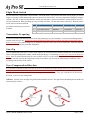
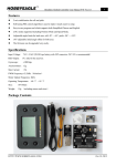
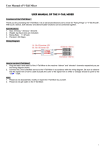
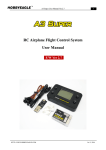
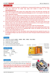
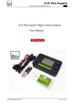
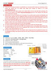
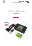
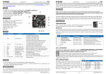
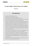
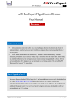
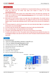
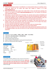
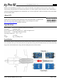
User Manual Version 1.0
1
Thank you for purchasing our products. The A3 Pro SE controller is the updated version of A3 Pro. After a fully
improvement and optimization of hardware and software, we make it lighter, smaller and more stable. Additionally it
supports both analog and digital servos and provides you 3 levels of gain ratio. All these functions can be setup simply
by an on-board button.
About S/N
A 13-bit unique product series number (S/N) was added to identify each unit, which can be
found in the bar code label on the packing box. Due to that the number is required in the
after-sale service and technical supports, please verify it through our website
http://www.hobbyeagle.com and keep it securely!
Specifications
Input Voltage: DC 5V~6V, powered from the receiver directly
Gyroscope:
±2000 dps, 1kHz
Servo Frequency: 50Hz for analog servos / 133Hz for digital servos
Servo Travel:
1520±500µs Limit 970-2070µs
Operating Temperature: -40 ℃ ~ 85 ℃
Size:
25×35mm
Weight:
6 g (excluding wires)
Installation
The controller must be firmly mounted on the platform of the airframe by using one of the provided double-sided tapes.
You can install it face up or face down, however, the pins must always point toward the front or rear of the aircraft (the
longer side of the board must be along with the heading direction) as shown below:
HTTP://WWW.HOBBYEAGLE.COM
Sept. 7, 2013
User Manual Version 1.0
2
Connection
Connect the controller to the receiver and servos according to the illustration below. Here we use a FUTABA R6008HS
receiver as an example. The aileron channel (CH1) should be connected onto the pin "Receiver[1]" on the board. The
elevator (CH2) should be connected onto "Receiver[2]" and the rudder (CH4) should be connected onto "Receiver[3]".
The throttle servo or ESC is connected as normal to the throttle channel (CH3) of the receiver without bridging the
board. The CH5 which connected to the "Receiver[4]" is assigned to a 3-position switch of the transmitter for switching
the flight mode during flight. The servos are connected to the pins "Servo", pin 1 for the aileron servo, pin 2 for the
elevator servo and pin 3 for the rudder servo. When the aileron is operated by two separate servos, you have to use a
Y-extension cable. Pay attention to the color of wires to avoid anti-plug. After wiring, the controller will be powered
from the receiver directly without additional power supply.
HTTP://WWW.HOBBYEAGLE.COM
Sept. 7, 2013
User Manual Version 1.0
3
Flight Mode Switch
To switch between 3 flight mode "Normal Mode / 3D Flight Mode / Gyro Deactivated Mode" during flight, you should
assign a 3-position switch channel and connect it onto the pin "Receiver[4]". You may implement it simply by using the
"GEAR", "FLAP" or other mixing functions within your transmitter. System will default to normal mode if you leave
this pin unconnected. When operating, the color of LEDs will show you that which mode currently is. Blue for normal
mode, Red for 3D mode and both
No. Flight Mode
Position
Pulse Range
LEDs
Off indicates that the gyro has been
1
Normal Mode▲
ON
< 1320µs
Solid Blue
disabled.
2
Gyro Deactivated
MIDDLE
1520±200µs
Both Off
3
3D Flight Mode
OFF
> 1720µs
Solid Red
Transmitter Preparing
Create a new model and choose the basic fixed-wing model type in your transmitter. Verify that all trimming buttons
and sub-trims are set to 0%. Disable any mixing functions for delta-wing or v-tail in your radio system, these will be
done by A3 Pro SE. Let other settings stay at default this moment such as Servo Travel (End Point), Dual Rate and EXP
etc. they can be adjusted as usual after installation.
Start Up
After completing the steps above, you are ready to power up. First turn on the transmitter, then power on the aircraft, the
LEDs will begin blinking Blue rapidly, which means that the gyro is calibrating. Do NOT move the aircraft during this
phase. After successful initialization, the color of LEDs will give you the information about which flight mode is
currently selected. Now flip the flight mode switch several times, you will see the LEDs change to different colors
according to the position of the switch.
Gyro Compensation Direction
It is extremely important to make sure that the gyros of all channels are compensating in the correct direction before
flight, otherwise it could lead to losing control or even crash during flight! To perform the examination, power on the
aircraft, pick the aircraft up and check it by following the illustrations below. If the gyro compensates in an incorrect
direction, reverse it in the setting mode.
Aileron Quickly move the right wing downward around the roll axis. The right aileron should flap down and the left
aileron flap up as shown.
HTTP://WWW.HOBBYEAGLE.COM
Sept. 7, 2013
4
User Manual Version 1.0
Elevator Quickly move the nose of the aircraft downward around the pitch axis. The elevator should flap up as
shown.
Rudder Quickly move the nose of the aircraft to the left around the yaw axis. The rudder should flap right as shown.
Setting Mode
1. Enter Setting Mode
Press and hold down the button for more than 2 seconds (long press), release it when the LEDs begin to blink Blue&Red
rapidly. In the setting menu, the LEDs should be blinking Blue&Red for N times in a loop with the sequence by the chart
below. N stands for the number of the setting function.
2. Function Selection
When you reach the function that you wish to operate in, quickly press the button once (short press) to enter it.
HTTP://WWW.HOBBYEAGLE.COM
Sept. 7, 2013
5
User Manual Version 1.0
No.
Setting Functions
1
Stick Centering
2
3
4
Wing Type Selection
Aileron Gyro Reversing
Elevator Gyro Reversing
5
Rudder Gyro Reversing
6
Servo Type Selection
7
Gain Ratio Selection
Solid Blue
Solid Red
Blue&Red
See "Stick Centering"
*Normal
Delta-wing
(Flying-wing)
V-tail
*Normal
Reversed
-
*Normal
Reversed
-
*Normal
Reversed
-
*Analog
(50Hz)
Digital
(133Hz)
-
Small
*Medium
Large
3. Change The Setting
After entering the function, the color of LEDs will show you the settings currently selected. Each short press of the
button advances the option to the next value. When you finish making your selections, just wait for 5 seconds then
system will save the modified and back to the setting menu automatically. The colors corresponding to the options for
each item are as shown in the preceding table. (* is the default setting)
4. Exit Setting Mode
When back to the menu, long press the button again to exit the setting mode.
e.g. How to change the wing type to "Delta-wing"?
Step 1 Long press the button to enter the setting mode.
Step 2 Short press the button when the LEDs blink Blue&Red twice to select the "Wing Type Selection" function.
Step 3 After entering, the LEDs change to a solid Blue which show you that the "Normal" is current selected.
Step 4 Short press the button again, the LEDs will change to a solid Red which indicates that you have changed the
setting to "Delta-wing".
Step 5 Wait for 5 seconds until back to the setting menu.
Step 6 Long press the button again to exit the setting mode.
Stick Centering
It is used to calibrate and remember the center pulse width of receipt signal. The controller has to re-learn the center
position of the sticks in the conditions as following:
HTTP://WWW.HOBBYEAGLE.COM
Sept. 7, 2013
User Manual Version 1.0
6
In what conditions a stick centering should be needed?
1.
2.
3.
4.
First-time use or after installation.
After replacing a new radio system.
After making a trimming or sub-trim change within the transmitter.
If the servos move to one side automatically when switching to 3D flight mode.
e.g. How to perform stick centering?
Step 1 Get the controller connected from the receiver first and turn on the transmitter, keep sticks of Aileron,
Elevator and Rudder in the middle position.
Step 2 Power on the controller and receiver, wait until it is ready to work.
Step 3 Long press the button to enter setting mode, short press the button when you reach the function "Stick
Centering". Once it begins, the LEDs will keep blinking Blue rapidly for about 1 second, don't move the sticks until it
blink Blue once again which means that calibration is done. It will return to the setting menu automatically after
calibration done.
Step 4 Long press the button again to exit the setting mode, now it is ready to fly.
Gain Adjustment
The trimming potentiometers on the board are used to adjust the gyro gain for Aileron, Elevator and
Rudder. Clockwise for increase, anticlockwise for decrease. The gain is affected by many factors
there is no standard answer to that how much it should be. You need to fine-tune carefully to get the
best result. Due to that the aircraft will become vibrative if the gain is too large, you'd better start
with a lower volume for the first flight and then increase it gradually. The adjustment will take effect
immediately without a restart.
Servo Type
This function is used to select the servo type that connected to the controller. A3 Pro SE provides 50Hz operating
frequency for analog servos and 133Hz for digital servos. Analog servos usually tolerate only 50Hz working frequency
and most digital servos allow higher frequencies, but you may need to check the manual of your servos. If you don't
know what the maximum frequency the servos can tolerate, please keep the default setting. A higher driving frequency
can lead to a failure of the servos!
Gain Ratio
In order to meet more needs, A3 Pro SE provides 3 levels of gain ratio including Small, Medium and Large. The default
is Medium which will be suitable for most aircrafts. You can choose a larger level when the current gain is still not large
enough even when it has been set to 100%. But remember that always use the ratio as small as possible to improve the
precision of adjustment.
After-sale Service
We provide 1 year free maintenance and service against fails of our products. Please visit our website
HTTP://WWW.HOBBYEAGLE.COM for more information about our products. If any questions are encountered
while setting up or operating the controller, please contact us via email [email protected].
HTTP://WWW.HOBBYEAGLE.COM
Sept. 7, 2013