1
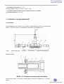
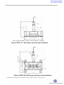
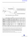
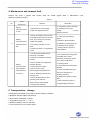
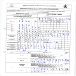
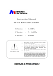
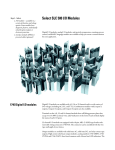
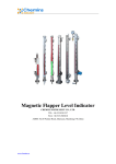
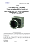
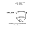
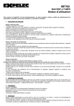
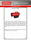
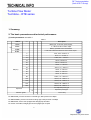
RLT Instrumentation
(Unit of RLT Group)
TECHNICAL INFO
Turbine Flow Meter
Techbine - RTB series
1. Summary.
2. The basic parameters and technical performance
(1) basic parameters: see table 1
Table 1
LWGY□
Type
□□□
□
□
□
Description
RTBY
Basic type, +5-24 DVC power supply,
RTBA
4 ~ 20mA two-wire current output
RTBB
Battery-powered local LCD indicator
Local LCD indicator/4~20mA two-wire current output
RTBC
DN(mm)
4
4mm, 0.04 ~ 0.25m3 / h
6
6mm, 0.1 ~ 0.6m3 / h
10
10mm, 0.2 ~ 1.2m3 / h
15
15mm, 0.6~6m3 / h
20
20mm, 0.8~8m3 / h
25
25mm, 1 ~ 10m3 / h
32
32mm, 1.6 ~ 16m3 / h
40
40mm, 2 ~ 20m3 / h
50
50mm, 4 ~ 40m3 / h
65
65mm, 8 ~ 80m3 / h
80
80mm, 10 ~ 100m3 / h
100
100mm, 20 ~ 200m3 / h
125
125mm, 25 ~ 250m3 / h
150
150mm, 30 ~ 300m3 / h
200
200mm, 80 ~ 800m3 / h
non-explosion-proof type
Explosion
Explosion-proof type
B
Precision grade
B
1% accuracy
For DN4-DN40, process connection is thread type, Max pressure is 6.3Mpa.
For DN50-DN200, process connection is flange type. Max.pressure is 2.5Mpa;
For DN4-DN10, sensor was equipped with straight pipe and filter.
For sensor over DN15, straight pipe can be equipped per request.
℃
People are our prime mover
RLT Instrumentation
(Unit of RLT Group)
1. T he ambient temperature: -20 ~ +55 ℃
2. Power supply: Voltage: +5-24 VDC, Current: ≤ 10mA
3. Transmitting distance from sensor to display instrument up to 1000m.
4. Medium temperature: -20 ~ +120
3. Installation, use and adjustment
(1) Installation
The installation type of sensors can be thread or flange based on sensor size. Please view
Figure 1, Figure 2, Figure 3, for installation. See table 2 for installation size.
1.Filter
2.Prior straight pipe
3. turbine
4.Pre-amplifier
5.body 6.rear straight pipe
Overall structure
×
Filter
×
RTBY -4~10 Sensors structure and Installation
1.pressing part, 2.Bolt 4 14, 3.washer, 4.Sealing gasket, 5.steel wire 1Cr18Ni9Ti-0.8
2.5, 6.Filter,
7.holder
People are our prime mover
RLT Instrumentation
(Unit of RLT Group)
1.body, 2.prior flow-guider, 3.turbine, 4.rear flow-guider, 5. amplifier
Figure 2 RTBY -15 ~ 40 sensors structure and installation
Figure 3 RTBY-50~200 Sensors Structure and Installation
1.Ball bearings, 2.prior flow-guider, 3.pressing part, 4.body, 5.amplifier, 6.turbine, 7. Bearings, 8. shaft
People are our prime mover
RLT Instrumentation
(Unit of RLT Group)
Figure 4 wiring between sensors and indicator
Table 2
D(mm)
d(mm)
287
Φ125
Φ160
Φ18
Φ18
4
8
322
367
Φ180
Φ250
Φ18
Φ25
8
8
DN(mm)
L(mm)
H(mm)
G
L'(mm)
4
6
275
275
145
G1/2
215
145
G1/2
215
455
75
165
173
G1/2
G1
350
RTBY-15
10
15
RTBY-25
25
100
180
G5/4
RTBY-40
40
50
140
150
178
252
G2
80
200
100
150
220
300
RTBY -4
RTBY-6
RTBY-10
RTBY-50
RTBY-80
RTBY-100
RTBY-150
Holes
◆Sensors can be installed horizontally or vertically. If the sensor was installed vertically, liquid shall
flow upward. Pipe shall be filled fully with liquid and without bulb. The direction of liquid flow shall
follow the arrow marked on the sensors. There shall be at least 20D straight pipe prior to the sensor
and 5D straight pipe behind the sensors. The wall inside should be smooth and clean. There shall
be no dents, fouling and furrow on wall inside. The axis of sensor should be aligned with the axis of
adjacent pipeline. Sealing gaskets shall not rise over wall inside.
◆Sensor should stay away from outside world electric and magnetic fields. If necessary, please
People are our prime mover
RLT Instrumentation
(Unit of RLT Group)
take effective screening measures in order to avoid external interference.
◆If sensors were installed outdoor, please take water-proof measure to protect the amplifier.
◆By-pass pie was suggested to install so that liquid transference does not have to be stopped
during overhaul.
◆If the fluid contains impurities, filter shall be installed. Filter mesh is up to the size of impurity.
Generally
mesh number 20-60 was suggested. When there's bulb in the fluid, air-eliminator
should be installed. The entire pipeline system should be sealed will.
◆Users should fully aware of the corrosions of medium to protect sensor against corrosion.
(2) Operation and adjustment
◆To keep liquid clean and no fiber and impurity.
◆Please open valve slowly and fill the sensor gradually. High water hamper to the empty sensor
was prohibited.
◆Normally sensor maintenance period is six months. During cleaning of
sensor, please pay
attention not to damage measurement cavity parts, especially the turbine. Before assembly, please
pay attention to the relationship between the turbine and flow-guider.
◆For storage, please clean the
liquid
inside the sensor, and cover 2 ends of
the sensor
against
impurity entering the sensor. Please keep the sensor in dry and clean place
◆For equipped filter, please clean it periodically. When it's not used, please clean and store it
just as to sensor.
◆Sensor's transmission cable can be laid overhead or underground (please put the cable
into
metal pipe if it's buried underground.)
◆Before sensors installed, please connect electrically the sensor to indicator to see whether
indicator shows flow when user rotates the turbine. If no flow displays on indicator, please check the
relevant part to kill trouble before installation.
People are our prime mover
RLT Instrumentation
(Unit of RLT Group)
4. Maintenance and common fault
Sensors may have a general fault. Please shoot the trouble against table 3. Maintenance cycle
should not exceed six months.
Table 3
No.
Fault
Display
1
Reasons
phenomenon
instrument shows
on flow
1. Connected to power, according
1. No powered or wrong voltage.
to requirements of a given
2. Fault with display instrument
voltage.
2. Check
display instrument.
1. Sensor and display instrument was
connected wrongly (open-circuit, short
2
Elimination
Display
circuit, poor contact, such as fault)
instrument works
2. Fault with amplifier
well but shows no
3. Converters (coil) open or short
flow.
circuit.
4. Turbine was stuck or no liquid flows
in pipe.
1. Check wiring according to
Figure
2. Repair or replace amplifier.
3. Repairing or replacing the coil.
4. Cleaning sensor and pipe.
Opening valves or pumps to
clean pipelines.
1. The actual flow exceeds sensor
flow-range or not stable.
2. Instrument coefficient K setting is
incorrect.
3. Sensor turbine was wrapped with
3
Display
impurities like fiber.
instrument does
4. There's bulb in the liquid.
work steadily or
5. Sensor next to strong
measurement is
electromagnetic field interference.
not correct.
6. Sensor bearings and shaft were
seriously worn.
7. Sensor shielded cable or other
grounding wires and lines
disconnected or bad grounded.
8. Display Instrument fault.
1. the measured flow-range shall
be suitable to the sensor
flow-range, to keep flow steady.
2. To correct coefficient K.
3. Cleaning sensor.
4. Take measures to eliminate air
bubbles.
5. As far as possible away from
sources of interference or
shielding measures.
6. Replace flow-guider or turbine
shaft
7. Wire according to Figure 4
8. Repair display instrument.
5. Transportation、storage
Transportation and storage in accordance with the following conditions:
a, Rainproof dampproof place and package
b, No mechanical vibrations or shocks
c, Temperature range -20 ℃ ~ +55 ℃
d, Relative humidity of not more than 80%
e, The environment is non-corrosive gases.
People are our prime mover