1
VTM-99-001
VEDAS II USER’S MANUAL
V ALCOM
E NVIRONMENTAL
D ATA
A CQUISITION
S YSTEM
Valcom Limited, 175 Southgate Drive, P.O. Box 603, Guelph, Ontario, Canada N1H 6L3
Tel: (519) 824-3220
Fax: (519) 824-3411
Web: www.valcom-guelph.com
E-mail: [email protected]
USER'S MANUAL
VEDAS II
Page i
REVISION SHEET
REVISION
LEVEL
PAGES
AFFECTED
DESCRIPTION OF CHANGE
DATE
--
--
Original Issue
14/01/99
A
Various
Minor grammatical corrections
and additions
27/01/00
B
Various
Added sections for Campbell
Scientific SAT HDR GOES
Transmitter.
Various minor format and
grammar changes.
18/03/02
Various
Added VGOES option for HDR
GOES Transmitter and updated
chapter 10, Entering Acquisition
Formulas.
27/02/06
Various
Increased the address range for
SDI-12 inputs and updated
section 5.2.1 Direct RF
Transmitter Communication
12/06/06
C
D
APPROVED
USER'S MANUAL
VEDAS II
Page ii
SAFETY
This product has been designed and tested a ccording to International Safety Requirements. To ensure safe operation and
to keep the produc t safe, the informa tion, cautions, a nd warning s in this manual, m ust be heed ed.
CERTIFICATION
Valcom certifies that this product met its published specifications at the time of shipment from the factory. Valcom
further certifies that its ca libration me asuremen ts are traceab le to the Unite d States N ational Bu reau of Stan dards, to
the extent allowed by the Bureau's calibration facility, and to the calibration facilities of other International Standards
Organization mem bers.
WARRANTY
This Valcom pro duct is warranted against defects in material and workmanship for a period of one year from date of
shipment. During the warranty period, Valcom will, at its option, either repair or replace products which prove to be
defective. For warranty service or repair, this product must be returned to a service facility designated by Valcom.
The warranty service for produc ts installed by Valcom and certain other products designated by Valcom could however,
be performed at the Buyer's facility at no charge within the Valcom service travel area.
LIMITATION OF WARRANTY
The foregoing warranty shall not apply to defects resulting from improper or inadequate maintenance by the Buyer,
Buyer-supplied software or interfacing, unauthorized modification or misuse, operation outside of the environmental
specifications for the product, or improper site preparation or maintenance.
NO OTHE R WAR RANTY IS EXPRE SSED OR IMPLIED . VALCOM SPECIF ICALLY DISCLAIMS THE IMPLIED
WARRANTIES OR MERCHANTABILITY AND FITNESS FOR A PARTICULAR PURPOSE.
CUSTOMER INQUIRIES
Inquiries reg arding the V edas II system may be ma de to Va lcom Limite d in Guelp h by either ph one, Fax, o r mail.
Valcom Limited
175 Southgate Drive
Guelph, Ontario.
CANADA N1H 6L3
Telephone:
Fax:
e-mail:
(519) 824-3220
(519) 824-3411
[email protected]
USER'S MANUAL
VEDAS II
Page iii
EQUIPMENT ATTACHMENT LIMITATIONS
RE: VEDAS TELEPHONE INTERFACE OPTION
NOTICE:
The Canadian Department of Communications label identifies certified equipment. This certification
means that equipm ent meets cer tain telecomm unications ne twork pro tective, operational and safety
requirements. The Department does not guarantee the equipment will operate to the users' satisfaction.
Before ins talling this equipme nt, users should ensure that it is per missible to connect the equipment to the facilities of
the local telecommunications company. The equipment must also be installed using an acceptable method of connection.
In some cases, the company's inside wiring associated with a single line individual service may be extended by means
of a certified connector assembly (telephone extension cord). T he custome r should be aware that compliance with the
above cond itions may not prevent degrad ation of service in some situations.
Repairs to certified equipment should be made by an authorized Canadian maintenance facility designated by the
supplier. Any repairs or alterations made by the user to this equipment, or equ ipment malfunctions, may give th e
telecomm unications co mpany ca use to disco nnect the eq uipment.
Users should ensure, for their own protection, that the electrical ground connections of the power utility, telephone lines,
and internal metallic water pipe system, if present, are connected together. This precaution may be particularly important
in rural areas.
CAUTION: Users should not attempt to make such connections themselves, but should contact the approp riate electric
inspection a uthority or elec trician.
The Load Number (LN) assigned to each terminal device denotes the percentage of the total load to be connected to a
telephone loop which is used by the device, to prevent overloading. The termination on a loop may consist of any
combination of devices subject only to the requirement that the total of Load Numbers of all the devices does not exceed
100.
SOFTWARE DISCLAIMER
WARNING: Users should not attempt to upgrade earlier versions of VEDAS II units with later versions of software than
what was originally installed.
As a result of continual improvements to the resident software on the VEDAS II units, trying to install later versions of
software than what was originally released with the unit may cause damage to the memory locations storing pertinent
information about the VEDAS II unit. This includes the calibration data (in the case of Level 2 units) and archived
information.
Valcom can not guarantee the reliable operation of the VEDAS II unit should such a software upgrade be attempted by
anyone other than a Valcom employee.
If software upgrades are requested or required, the VEDAS II units should be returned to Valcom to perform the work.
USER'S MANUAL
VEDAS II
Page iv
Table Of Contents
Page
Section 1.0
1.1
1.2
1.3
1.4
1.5
1.6
1.7
INTRODUCTION
Purpos e and Sco pe of M anual . . . . . . . . . . . . . . . . . . . . . . . . . . . . . . . . . . . . . . . . . . . . . . . . . . . . . . .
System Description/Capabilities . . . . . . . . . . . . . . . . . . . . . . . . . . . . . . . . . . . . . . . . . . . . . . . . . . . . . .
System Re quiremen ts . . . . . . . . . . . . . . . . . . . . . . . . . . . . . . . . . . . . . . . . . . . . . . . . . . . . . . . . . . . . . .
System Specifications . . . . . . . . . . . . . . . . . . . . . . . . . . . . . . . . . . . . . . . . . . . . . . . . . . . . . . . . . . . . . .
System Procurement Options . . . . . . . . . . . . . . . . . . . . . . . . . . . . . . . . . . . . . . . . . . . . . . . . . . . . . . . .
System Limitations . . . . . . . . . . . . . . . . . . . . . . . . . . . . . . . . . . . . . . . . . . . . . . . . . . . . . . . . . . . . . . . .
Vedas II Utility Program . . . . . . . . . . . . . . . . . . . . . . . . . . . . . . . . . . . . . . . . . . . . . . . . . . . . . . . . . . .
1-1
1-2
1-3
1-3
1-6
1-7
1-7
Section 2.0
HARDWARE CONNECTIONS
2.1
System Grounding . . . . . . . . . . . . . . . . . . . . . . . . . . . . . . . . . . . . . . . . . . . . . . . . . . . . . . . . . . . . . . . . 2-1
2.2
Termina l Strip . . . . . . . . . . . . . . . . . . . . . . . . . . . . . . . . . . . . . . . . . . . . . . . . . . . . . . . . . . . . . . . . . . . . 2-1
2.2.1
Shield Connections . . . . . . . . . . . . . . . . . . . . . . . . . . . . . . . . . . . . . . . . . . . . . . . . . . . . . . . . . . . . . . . . 2-2
2.2.2
Ground Connections . . . . . . . . . . . . . . . . . . . . . . . . . . . . . . . . . . . . . . . . . . . . . . . . . . . . . . . . . . . . . . . 2-2
2.2.2.1
Power Co nnector (+12 vo lts) . . . . . . . . . . . . . . . . . . . . . . . . . . . . . . . . . . . . . . . . . . . . . . . . . . . . . . . . 2-2
2.2.2.2
Program Terminal Connector . . . . . . . . . . . . . . . . . . . . . . . . . . . . . . . . . . . . . . . . . . . . . . . . . . . . . . . . 2-2
2.2.2.3
12 Vo lt Outputs . . . . . . . . . . . . . . . . . . . . . . . . . . . . . . . . . . . . . . . . . . . . . . . . . . . . . . . . . . . . . . . . . . 2-2
2.2.2.4
12 Vo lt Switched O utputs . . . . . . . . . . . . . . . . . . . . . . . . . . . . . . . . . . . . . . . . . . . . . . . . . . . . . . . . . . . 2-2
2.2.2.5
5 Volt Controlled Output . . . . . . . . . . . . . . . . . . . . . . . . . . . . . . . . . . . . . . . . . . . . . . . . . . . . . . . . . . . 2-2
2.2.2.6
Phone Jack . . . . . . . . . . . . . . . . . . . . . . . . . . . . . . . . . . . . . . . . . . . . . . . . . . . . . . . . . . . . . . . . . . . . . . 2-2
2.2.2.7
RS-232 Serial Port . . . . . . . . . . . . . . . . . . . . . . . . . . . . . . . . . . . . . . . . . . . . . . . . . . . . . . . . . . . . . . . . 2-2
2.2.2.8
RS-485 Serial Port . . . . . . . . . . . . . . . . . . . . . . . . . . . . . . . . . . . . . . . . . . . . . . . . . . . . . . . . . . . . . . . . 2-3
2.2.2.9
SDI-12 . . . . . . . . . . . . . . . . . . . . . . . . . . . . . . . . . . . . . . . . . . . . . . . . . . . . . . . . . . . . . . . . . . . . . . . . . 2-3
2.2.3
Analog Interface Connection . . . . . . . . . . . . . . . . . . . . . . . . . . . . . . . . . . . . . . . . . . . . . . . . . . . . . . . . 2-3
2.2.3.1
Analog In put Chann els . . . . . . . . . . . . . . . . . . . . . . . . . . . . . . . . . . . . . . . . . . . . . . . . . . . . . . . . . . . . . 2-3
2.2.3.2
Reference Voltage C hannels . . . . . . . . . . . . . . . . . . . . . . . . . . . . . . . . . . . . . . . . . . . . . . . . . . . . . . . . . 2-4
2.2.4
Digital Interface Connections . . . . . . . . . . . . . . . . . . . . . . . . . . . . . . . . . . . . . . . . . . . . . . . . . . . . . . . . 2-4
2.2.4.1
Digital Inpu ts . . . . . . . . . . . . . . . . . . . . . . . . . . . . . . . . . . . . . . . . . . . . . . . . . . . . . . . . . . . . . . . . . . . . 2-4
2.2.4.2
Digital Outp uts . . . . . . . . . . . . . . . . . . . . . . . . . . . . . . . . . . . . . . . . . . . . . . . . . . . . . . . . . . . . . . . . . . . 2-4
2.2.4.3
High Speed Event . . . . . . . . . . . . . . . . . . . . . . . . . . . . . . . . . . . . . . . . . . . . . . . . . . . . . . . . . . . . . . . . . 2-4
2.2.4.4
Pulse Counter Inputs, PC0 - PC4 . . . . . . . . . . . . . . . . . . . . . . . . . . . . . . . . . . . . . . . . . . . . . . . . . . . . . 2-4
2.2.4.5
Connection Examples . . . . . . . . . . . . . . . . . . . . . . . . . . . . . . . . . . . . . . . . . . . . . . . . . . . . . . . . . . . . . . 2-5
2.2.5
Power (b attery) . . . . . . . . . . . . . . . . . . . . . . . . . . . . . . . . . . . . . . . . . . . . . . . . . . . . . . . . . . . . . . . . . . . 2-6
2.2.6
Program Terminal . . . . . . . . . . . . . . . . . . . . . . . . . . . . . . . . . . . . . . . . . . . . . . . . . . . . . . . . . . . . . . . . . 2-6
2.2.7
SDI-12 Channels . . . . . . . . . . . . . . . . . . . . . . . . . . . . . . . . . . . . . . . . . . . . . . . . . . . . . . . . . . . . . . . . . . 2-6
2.2.8
RS-232 Port to Modem . . . . . . . . . . . . . . . . . . . . . . . . . . . . . . . . . . . . . . . . . . . . . . . . . . . . . . . . . . . . . 2-6
2.2.9
RS-232 Port to Terminal . . . . . . . . . . . . . . . . . . . . . . . . . . . . . . . . . . . . . . . . . . . . . . . . . . . . . . . . . . . . 2-6
2.2.10
Telephone/Modem Interface . . . . . . . . . . . . . . . . . . . . . . . . . . . . . . . . . . . . . . . . . . . . . . . . . . . . . . . . . 2-7
2.2.11
UHF Antenna . . . . . . . . . . . . . . . . . . . . . . . . . . . . . . . . . . . . . . . . . . . . . . . . . . . . . . . . . . . . . . . . . . . . 2-7
2.2.12
RF TX Power Monitor . . . . . . . . . . . . . . . . . . . . . . . . . . . . . . . . . . . . . . . . . . . . . . . . . . . . . . . . . . . . . 2-7
2.3
Internal Configurations . . . . . . . . . . . . . . . . . . . . . . . . . . . . . . . . . . . . . . . . . . . . . . . . . . . . . . . . . . . . . 2-8
2.3.1
Clock Battery . . . . . . . . . . . . . . . . . . . . . . . . . . . . . . . . . . . . . . . . . . . . . . . . . . . . . . . . . . . . . . . . . . . . 2-8
2.3.2
Internal Jumper Settings . . . . . . . . . . . . . . . . . . . . . . . . . . . . . . . . . . . . . . . . . . . . . . . . . . . . . . . . . . . . 2-8
Section 3.0
3.1
3.2
3.3
3.4
3.5
SYSTEM CONFIGURATION
System Hookup . . . . . . . . . . . . . . . . . . . . . . . . . . . . . . . . . . . . . . . . . . . . . . . . . . . . . . . . . . . . . . . . . . . 3-1
AutoBaud Mode . . . . . . . . . . . . . . . . . . . . . . . . . . . . . . . . . . . . . . . . . . . . . . . . . . . . . . . . . . . . . . . . . . 3-1
Vedas II Program Monitor System . . . . . . . . . . . . . . . . . . . . . . . . . . . . . . . . . . . . . . . . . . . . . . . . . . . . 3-1
Vedas II Start-Up Sequence . . . . . . . . . . . . . . . . . . . . . . . . . . . . . . . . . . . . . . . . . . . . . . . . . . . . . . . . . 3-1
Menu System . . . . . . . . . . . . . . . . . . . . . . . . . . . . . . . . . . . . . . . . . . . . . . . . . . . . . . . . . . . . . . . . . . . . 3-2
USER'S MANUAL
VEDAS II
Page v
Table Of Contents
3.5.1
3.5.1.1
3.5.1.2
3.5.1.3
3.5.1.4
3.5.1.5
3.5.1.6
3.5.1.7
3.5.1.8
3.5.1.9
3.5.1.10
3.5.2
3.5.2.1
3.5.2.2
3.5.2.3
3.5.2.4
3.5.2.5
3.5.2.6
3.5.2.7
3.5.2.8
3.5.2.9
3.5.2.10
3.5.2.11
3.5.2.12
3.5.3
3.5.3.1
3.5.3.2
3.5.3.3
3.5.3.4
3.5.3.5
3.5.3.6
3.5.3.7
3.5.3.8
3.5.3.9
3.5.3.10
3.5.3.11
3.5.4
3.5.4.1
3.5.4.2
3.5.4.3
3.5.4.4
3.5.4.5
3.5.4.6
3.5.4.7
3.5.4.8
3.5.4.9
3.5.5
Main Menu . . . . . . . . . . . . . . . . . . . . . . . . . . . . . . . . . . . . . . . . . . . . . . . . . . . . . . . . . . . . . . . . . . . . . . 3-2
Add Ta sk . . . . . . . . . . . . . . . . . . . . . . . . . . . . . . . . . . . . . . . . . . . . . . . . . . . . . . . . . . . . . . . . . . . . . . . 3-3
Edit Task . . . . . . . . . . . . . . . . . . . . . . . . . . . . . . . . . . . . . . . . . . . . . . . . . . . . . . . . . . . . . . . . . . . . . . . . 3-3
Delete Task . . . . . . . . . . . . . . . . . . . . . . . . . . . . . . . . . . . . . . . . . . . . . . . . . . . . . . . . . . . . . . . . . . . . . . 3-3
Display V edas II Sch edule . . . . . . . . . . . . . . . . . . . . . . . . . . . . . . . . . . . . . . . . . . . . . . . . . . . . . . . . . . 3-3
Detailed Task Display . . . . . . . . . . . . . . . . . . . . . . . . . . . . . . . . . . . . . . . . . . . . . . . . . . . . . . . . . . . . . . 3-5
Vedas II Configuration Menu . . . . . . . . . . . . . . . . . . . . . . . . . . . . . . . . . . . . . . . . . . . . . . . . . . . . . . . . 3-5
Operator Mode M enu . . . . . . . . . . . . . . . . . . . . . . . . . . . . . . . . . . . . . . . . . . . . . . . . . . . . . . . . . . . . . . 3-6
Diagnostic Menu . . . . . . . . . . . . . . . . . . . . . . . . . . . . . . . . . . . . . . . . . . . . . . . . . . . . . . . . . . . . . . . . . . 3-6
Calibrate Task . . . . . . . . . . . . . . . . . . . . . . . . . . . . . . . . . . . . . . . . . . . . . . . . . . . . . . . . . . . . . . . . . . . . 3-6
Archive Program Parameters . . . . . . . . . . . . . . . . . . . . . . . . . . . . . . . . . . . . . . . . . . . . . . . . . . . . . . . . 3-6
Vedas II Configuration Menu . . . . . . . . . . . . . . . . . . . . . . . . . . . . . . . . . . . . . . . . . . . . . . . . . . . . . . . . 3-7
Setup Program Terminal Interface . . . . . . . . . . . . . . . . . . . . . . . . . . . . . . . . . . . . . . . . . . . . . . . . . . . . 3-7
Set Station Number/Name . . . . . . . . . . . . . . . . . . . . . . . . . . . . . . . . . . . . . . . . . . . . . . . . . . . . . . . . . . 3-7
Set D ate/tim e/G M T . . . . . . . . . . . . . . . . . . . . . . . . . . . . . . . . . . . . . . . . . . . . . . . . . . . . . . . . . . . . . . . 3-7
Set Date Format . . . . . . . . . . . . . . . . . . . . . . . . . . . . . . . . . . . . . . . . . . . . . . . . . . . . . . . . . . . . . . . . . . 3-7
Set Error Log Modes . . . . . . . . . . . . . . . . . . . . . . . . . . . . . . . . . . . . . . . . . . . . . . . . . . . . . . . . . . . . . . 3-7
Set Archive Memory Modes . . . . . . . . . . . . . . . . . . . . . . . . . . . . . . . . . . . . . . . . . . . . . . . . . . . . . . . . . 3-7
Set Power Down Vo ltage . . . . . . . . . . . . . . . . . . . . . . . . . . . . . . . . . . . . . . . . . . . . . . . . . . . . . . . . . . . 3-7
Setup Modem Interface . . . . . . . . . . . . . . . . . . . . . . . . . . . . . . . . . . . . . . . . . . . . . . . . . . . . . . . . . . . . . 3-8
Enter Fo rmula . . . . . . . . . . . . . . . . . . . . . . . . . . . . . . . . . . . . . . . . . . . . . . . . . . . . . . . . . . . . . . . . . . . . 3-8
Send Program Parameters . . . . . . . . . . . . . . . . . . . . . . . . . . . . . . . . . . . . . . . . . . . . . . . . . . . . . . . . . . . 3-8
Overwrite Program Parameters . . . . . . . . . . . . . . . . . . . . . . . . . . . . . . . . . . . . . . . . . . . . . . . . . . . . . . . 3-8
Set Menu Language . . . . . . . . . . . . . . . . . . . . . . . . . . . . . . . . . . . . . . . . . . . . . . . . . . . . . . . . . . . . . . . 3-8
Operator Mode M enu . . . . . . . . . . . . . . . . . . . . . . . . . . . . . . . . . . . . . . . . . . . . . . . . . . . . . . . . . . . . . . 3-8
Immediate Task Execution . . . . . . . . . . . . . . . . . . . . . . . . . . . . . . . . . . . . . . . . . . . . . . . . . . . . . . . . . . 3-8
View Arc hived Da ta . . . . . . . . . . . . . . . . . . . . . . . . . . . . . . . . . . . . . . . . . . . . . . . . . . . . . . . . . . . . . . . 3-9
Send Ar chived D ata . . . . . . . . . . . . . . . . . . . . . . . . . . . . . . . . . . . . . . . . . . . . . . . . . . . . . . . . . . . . . . . 3-9
Display Current Output Message . . . . . . . . . . . . . . . . . . . . . . . . . . . . . . . . . . . . . . . . . . . . . . . . . . . . . 3-9
Create Emergency Message . . . . . . . . . . . . . . . . . . . . . . . . . . . . . . . . . . . . . . . . . . . . . . . . . . . . . . . . . 3-9
Display Formula List . . . . . . . . . . . . . . . . . . . . . . . . . . . . . . . . . . . . . . . . . . . . . . . . . . . . . . . . . . . . . . 3-9
Test Fo rmula . . . . . . . . . . . . . . . . . . . . . . . . . . . . . . . . . . . . . . . . . . . . . . . . . . . . . . . . . . . . . . . . . . . . . 3-9
Display Resident T ask List . . . . . . . . . . . . . . . . . . . . . . . . . . . . . . . . . . . . . . . . . . . . . . . . . . . . . . . . . 3-10
Display PCMCIA Information . . . . . . . . . . . . . . . . . . . . . . . . . . . . . . . . . . . . . . . . . . . . . . . . . . . . . . 3-10
Erase/Format PCMC IA Card . . . . . . . . . . . . . . . . . . . . . . . . . . . . . . . . . . . . . . . . . . . . . . . . . . . . . . . 3-10
Upgrade Vedas II Software From P CMCIA C ard . . . . . . . . . . . . . . . . . . . . . . . . . . . . . . . . . . . . . . 3-10
Diagnostic Menu . . . . . . . . . . . . . . . . . . . . . . . . . . . . . . . . . . . . . . . . . . . . . . . . . . . . . . . . . . . . . . . . 3-10
Direct RF Transmitter Communication . . . . . . . . . . . . . . . . . . . . . . . . . . . . . . . . . . . . . . . . . . . . . . 3-10
Direct SDI-12 . . . . . . . . . . . . . . . . . . . . . . . . . . . . . . . . . . . . . . . . . . . . . . . . . . . . . . . . . . . . . . . . . 3-10
Direct Serial Communication . . . . . . . . . . . . . . . . . . . . . . . . . . . . . . . . . . . . . . . . . . . . . . . . . . . . . . 3-10
SDI-12 Co mmunication Loo pback Te st . . . . . . . . . . . . . . . . . . . . . . . . . . . . . . . . . . . . . . . . . . . . . . 3-10
Test Display and Keypad . . . . . . . . . . . . . . . . . . . . . . . . . . . . . . . . . . . . . . . . . . . . . . . . . . . . . . . . . 3-10
Test FLASH . . . . . . . . . . . . . . . . . . . . . . . . . . . . . . . . . . . . . . . . . . . . . . . . . . . . . . . . . . . . . . . . . . . 3-11
Clear Archive Memory . . . . . . . . . . . . . . . . . . . . . . . . . . . . . . . . . . . . . . . . . . . . . . . . . . . . . . . . . . . 3-11
Display Error Log . . . . . . . . . . . . . . . . . . . . . . . . . . . . . . . . . . . . . . . . . . . . . . . . . . . . . . . . . . . . . . . 3-11
Display Vedas II Information . . . . . . . . . . . . . . . . . . . . . . . . . . . . . . . . . . . . . . . . . . . . . . . . . . . . . . 3-11
Calibrate Task . . . . . . . . . . . . . . . . . . . . . . . . . . . . . . . . . . . . . . . . . . . . . . . . . . . . . . . . . . . . . . . . . . 3-11
Section 4.0
ACQUISITION PROGRAMMING
4.1
Introduction . . . . . . . . . . . . . . . . . . . . . . . . . . . . . . . . . . . . . . . . . . . . . . . . . . . . . . . . . . . . . . . . . . . . . 4-1
4.2
General Information . . . . . . . . . . . . . . . . . . . . . . . . . . . . . . . . . . . . . . . . . . . . . . . . . . . . . . . . . . . . . . . 4-1
4.2.1
Parame ter Defaults . . . . . . . . . . . . . . . . . . . . . . . . . . . . . . . . . . . . . . . . . . . . . . . . . . . . . . . . . . . . . . . . 4-1
USER'S MANUAL
VEDAS II
Page vi
Table Of Contents
4.2.2
4.2.3
4.2.4
4.2.5
4.3
4.3.1
4.3.1.1
4.3.1.2
4.3.1.3
4.3.1.4
4.3.1.5
4.3.1.6
4.3.1.7
4.3.1.8
4.3.1.9
4.3.1.10
4.3.1.11
4.3.1.12
4.3.1.13
4.3.1.14
4.3.1.15
4.3.1.16
4.3.2
4.3.2.1
4.3.2.1.1
4.3.2.1.2
4.3.2.1.3
4.3.2.1.4
4.3.2.2
4.3.2.3
4.3.2.4
4.3.2.4.1
4.3.2.4.2
4.3.2.4.3
4.3.2.4.4
4.3.2.4.5
4.3.2.4.6
4.3.2.4.7
4.3.2.4.8
4.3.2.4.9
4.3.2.4.10
4.3.3
4.3.3.1
4.3.3.1.1
4.3.3.1.1 .1
4.3.3.1.1 .2
4.3.3.1.1 .3
4.3.3.1.1 .4
4.3.3.1.1 .5
4.3.3.1.1 .6
4.3.3.1.2
4.3.3.2
GOES Update Time . . . . . . . . . . . . . . . . . . . . . . . . . . . . . . . . . . . . . . . . . . . . . . . . . . . . . . . . . . . . . . . 4-1
Midnight Violations . . . . . . . . . . . . . . . . . . . . . . . . . . . . . . . . . . . . . . . . . . . . . . . . . . . . . . . . . . . . . . . 4-1
Hardware Contentions . . . . . . . . . . . . . . . . . . . . . . . . . . . . . . . . . . . . . . . . . . . . . . . . . . . . . . . . . . . . . 4-1
Sensor Warmup . . . . . . . . . . . . . . . . . . . . . . . . . . . . . . . . . . . . . . . . . . . . . . . . . . . . . . . . . . . . . . . . . . 4-2
Data Acquisition Tasks . . . . . . . . . . . . . . . . . . . . . . . . . . . . . . . . . . . . . . . . . . . . . . . . . . . . . . . . . . . . . 4-2
Comm on Task Elements . . . . . . . . . . . . . . . . . . . . . . . . . . . . . . . . . . . . . . . . . . . . . . . . . . . . . . . . . . . . 4-2
Task P riority . . . . . . . . . . . . . . . . . . . . . . . . . . . . . . . . . . . . . . . . . . . . . . . . . . . . . . . . . . . . . . . . . . . . . 4-2
Task Label . . . . . . . . . . . . . . . . . . . . . . . . . . . . . . . . . . . . . . . . . . . . . . . . . . . . . . . . . . . . . . . . . . . . . . 4-2
Start Of Acquisition . . . . . . . . . . . . . . . . . . . . . . . . . . . . . . . . . . . . . . . . . . . . . . . . . . . . . . . . . . . . . . . 4-2
Interval Of Acquisition . . . . . . . . . . . . . . . . . . . . . . . . . . . . . . . . . . . . . . . . . . . . . . . . . . . . . . . . . . . . . 4-2
Number Of Samples . . . . . . . . . . . . . . . . . . . . . . . . . . . . . . . . . . . . . . . . . . . . . . . . . . . . . . . . . . . . . . . 4-2
Period Of Acquisition . . . . . . . . . . . . . . . . . . . . . . . . . . . . . . . . . . . . . . . . . . . . . . . . . . . . . . . . . . . . . . 4-3
Sample Option . . . . . . . . . . . . . . . . . . . . . . . . . . . . . . . . . . . . . . . . . . . . . . . . . . . . . . . . . . . . . . . . . . . 4-3
Archive Acquisition . . . . . . . . . . . . . . . . . . . . . . . . . . . . . . . . . . . . . . . . . . . . . . . . . . . . . . . . . . . . . . . 4-3
Number of TX Archives . . . . . . . . . . . . . . . . . . . . . . . . . . . . . . . . . . . . . . . . . . . . . . . . . . . . . . . . . . . . 4-3
TX Archive Offset . . . . . . . . . . . . . . . . . . . . . . . . . . . . . . . . . . . . . . . . . . . . . . . . . . . . . . . . . . . . . . . . 4-4
TX Archive Interval . . . . . . . . . . . . . . . . . . . . . . . . . . . . . . . . . . . . . . . . . . . . . . . . . . . . . . . . . . . . . . . 4-4
Formula Number . . . . . . . . . . . . . . . . . . . . . . . . . . . . . . . . . . . . . . . . . . . . . . . . . . . . . . . . . . . . . . . . . . 4-4
Calibration Gain . . . . . . . . . . . . . . . . . . . . . . . . . . . . . . . . . . . . . . . . . . . . . . . . . . . . . . . . . . . . . . . . . . 4-4
Calibration Offset . . . . . . . . . . . . . . . . . . . . . . . . . . . . . . . . . . . . . . . . . . . . . . . . . . . . . . . . . . . . . . . . . 4-5
Alarm Lim it . . . . . . . . . . . . . . . . . . . . . . . . . . . . . . . . . . . . . . . . . . . . . . . . . . . . . . . . . . . . . . . . . . . . . 4-5
Attach Alarm To Task . . . . . . . . . . . . . . . . . . . . . . . . . . . . . . . . . . . . . . . . . . . . . . . . . . . . . . . . . . . . . 4-5
Analog Sensor T ask . . . . . . . . . . . . . . . . . . . . . . . . . . . . . . . . . . . . . . . . . . . . . . . . . . . . . . . . . . . . . . . 4-6
Analog In puts . . . . . . . . . . . . . . . . . . . . . . . . . . . . . . . . . . . . . . . . . . . . . . . . . . . . . . . . . . . . . . . . . . . . 4-6
Differential . . . . . . . . . . . . . . . . . . . . . . . . . . . . . . . . . . . . . . . . . . . . . . . . . . . . . . . . . . . . . . . . . . . . . . 4-6
Single Ended . . . . . . . . . . . . . . . . . . . . . . . . . . . . . . . . . . . . . . . . . . . . . . . . . . . . . . . . . . . . . . . . . . . . . 4-6
Using Reference Voltage . . . . . . . . . . . . . . . . . . . . . . . . . . . . . . . . . . . . . . . . . . . . . . . . . . . . . . . . . . . 4-6
Using +12 Volt Strobe . . . . . . . . . . . . . . . . . . . . . . . . . . . . . . . . . . . . . . . . . . . . . . . . . . . . . . . . . . . . . 4-6
Battery Voltage Measurement . . . . . . . . . . . . . . . . . . . . . . . . . . . . . . . . . . . . . . . . . . . . . . . . . . . . . . . 4-6
Temperature, Internal . . . . . . . . . . . . . . . . . . . . . . . . . . . . . . . . . . . . . . . . . . . . . . . . . . . . . . . . . . . . . . 4-6
Analog Acquisition Task Programming . . . . . . . . . . . . . . . . . . . . . . . . . . . . . . . . . . . . . . . . . . . . . . . . 4-7
Task P riority . . . . . . . . . . . . . . . . . . . . . . . . . . . . . . . . . . . . . . . . . . . . . . . . . . . . . . . . . . . . . . . . . . . . . 4-7
Input Type . . . . . . . . . . . . . . . . . . . . . . . . . . . . . . . . . . . . . . . . . . . . . . . . . . . . . . . . . . . . . . . . . . . . . . 4-7
Analog In put Chann el . . . . . . . . . . . . . . . . . . . . . . . . . . . . . . . . . . . . . . . . . . . . . . . . . . . . . . . . . . . . . 4-7
Measurement Type . . . . . . . . . . . . . . . . . . . . . . . . . . . . . . . . . . . . . . . . . . . . . . . . . . . . . . . . . . . . . . . . 4-7
Analog Output Voltage . . . . . . . . . . . . . . . . . . . . . . . . . . . . . . . . . . . . . . . . . . . . . . . . . . . . . . . . . . . . . 4-7
Analog Output Channel . . . . . . . . . . . . . . . . . . . . . . . . . . . . . . . . . . . . . . . . . . . . . . . . . . . . . . . . . . . . 4-7
Switched 12 Volt Output . . . . . . . . . . . . . . . . . . . . . . . . . . . . . . . . . . . . . . . . . . . . . . . . . . . . . . . . . . . 4-7
Output Settling Time . . . . . . . . . . . . . . . . . . . . . . . . . . . . . . . . . . . . . . . . . . . . . . . . . . . . . . . . . . . . . . 4-7
Amplifier G ain . . . . . . . . . . . . . . . . . . . . . . . . . . . . . . . . . . . . . . . . . . . . . . . . . . . . . . . . . . . . . . . . . . . 4-8
Comm on Task Elements . . . . . . . . . . . . . . . . . . . . . . . . . . . . . . . . . . . . . . . . . . . . . . . . . . . . . . . . . . . . 4-8
Digital Sensor Tasks . . . . . . . . . . . . . . . . . . . . . . . . . . . . . . . . . . . . . . . . . . . . . . . . . . . . . . . . . . . . . . . 4-8
Parallel Input . . . . . . . . . . . . . . . . . . . . . . . . . . . . . . . . . . . . . . . . . . . . . . . . . . . . . . . . . . . . . . . . . . . . 4-8
Task Programming . . . . . . . . . . . . . . . . . . . . . . . . . . . . . . . . . . . . . . . . . . . . . . . . . . . . . . . . . . . . . . . . 4-8
Task P riority . . . . . . . . . . . . . . . . . . . . . . . . . . . . . . . . . . . . . . . . . . . . . . . . . . . . . . . . . . . . . . . . . . . . . 4-8
Least Significant Bit Number . . . . . . . . . . . . . . . . . . . . . . . . . . . . . . . . . . . . . . . . . . . . . . . . . . . . . . . . 4-8
Numb er Of Significa nt Bits . . . . . . . . . . . . . . . . . . . . . . . . . . . . . . . . . . . . . . . . . . . . . . . . . . . . . . . . . 4-8
Bit Input Mode . . . . . . . . . . . . . . . . . . . . . . . . . . . . . . . . . . . . . . . . . . . . . . . . . . . . . . . . . . . . . . . . . . . 4-8
Invert Input . . . . . . . . . . . . . . . . . . . . . . . . . . . . . . . . . . . . . . . . . . . . . . . . . . . . . . . . . . . . . . . . . . . . . 4-8
Numb er of Outp ut Bits . . . . . . . . . . . . . . . . . . . . . . . . . . . . . . . . . . . . . . . . . . . . . . . . . . . . . . . . . . . . . 4-9
Comm on Task Elements . . . . . . . . . . . . . . . . . . . . . . . . . . . . . . . . . . . . . . . . . . . . . . . . . . . . . . . . . . . . 4-9
Pulse Counter Tasks . . . . . . . . . . . . . . . . . . . . . . . . . . . . . . . . . . . . . . . . . . . . . . . . . . . . . . . . . . . . . . . 4-9
USER'S MANUAL
VEDAS II
Page vii
Table Of Contents
4.3.3.2.1
4.3.3.2.1 .1
4.3.3.2.1 .2
4.3.3.2.1 .3
4.3.3.2.2
4.3.3.3
4.3.3.3.1
4.3.3.3.1 .1
4.3.3.3.1 .2
4.3.3.3.1 .3
4.3.3.4
4.3.3.4.1
4.3.3.4.1 .1
4.3.3.4.1 .2
4.3.3.4.1 .3
4.3.4
4.3.4.1
4.3.4.2
4.3.4.2.1
4.3.4.2.1 .1
4.3.4.2.1 .2
4.3.4.2.1 .3
4.3.4.2.1 .4
4.3.4.2.1 .5
4.3.4.2.1 .6
4.3.4.2.1 .7
4.3.4.2.1 .8
4.3.4.2.1 .9
4.3.4.2.2
4.3.5
4.3.5.1
4.3.5.2
4.3.5.2.1
4.3.5.2.2
4.3.5.2.3
4.3.5.2.4
4.3.5.2.4 .1
4.3.5.2.5
4.3.6
4.3.6.1
4.3.6.1.1
4.3.6.1.2
4.4
4.4.1
4.4.1.1
4.4.1.1.1
4.4.1.1.2
4.4.1.1.3
4.4.1.1.4
4.4.1.1.5
4.4.1.1.6
4.4.1.1.7
Task Programming . . . . . . . . . . . . . . . . . . . . . . . . . . . . . . . . . . . . . . . . . . . . . . . . . . . . . . . . . . . . . . . . 4-9
Pulse Counter Channel . . . . . . . . . . . . . . . . . . . . . . . . . . . . . . . . . . . . . . . . . . . . . . . . . . . . . . . . . . . . . 4-9
Transition Level . . . . . . . . . . . . . . . . . . . . . . . . . . . . . . . . . . . . . . . . . . . . . . . . . . . . . . . . . . . . . . . . . . 4-9
Reset Co unter After E ach Samp le . . . . . . . . . . . . . . . . . . . . . . . . . . . . . . . . . . . . . . . . . . . . . . . . . . . . 4-9
Comm on Task Elements . . . . . . . . . . . . . . . . . . . . . . . . . . . . . . . . . . . . . . . . . . . . . . . . . . . . . . . . . . . . 4-9
Shaft Encoder . . . . . . . . . . . . . . . . . . . . . . . . . . . . . . . . . . . . . . . . . . . . . . . . . . . . . . . . . . . . . . . . . . . . 4-9
Task Programming . . . . . . . . . . . . . . . . . . . . . . . . . . . . . . . . . . . . . . . . . . . . . . . . . . . . . . . . . . . . . . . . 4-9
Shaft Enco der Chan nel LSB Bit . . . . . . . . . . . . . . . . . . . . . . . . . . . . . . . . . . . . . . . . . . . . . . . . . . . . . . 4-9
Switched 12 Volt Output . . . . . . . . . . . . . . . . . . . . . . . . . . . . . . . . . . . . . . . . . . . . . . . . . . . . . . . . . . . 4-9
Comm on Task Elements . . . . . . . . . . . . . . . . . . . . . . . . . . . . . . . . . . . . . . . . . . . . . . . . . . . . . . . . . . . . 4-9
High Speed Acquisition . . . . . . . . . . . . . . . . . . . . . . . . . . . . . . . . . . . . . . . . . . . . . . . . . . . . . . . . . . . 4-10
Task Programming . . . . . . . . . . . . . . . . . . . . . . . . . . . . . . . . . . . . . . . . . . . . . . . . . . . . . . . . . . . . . . . 4-10
High Speed Input Channel . . . . . . . . . . . . . . . . . . . . . . . . . . . . . . . . . . . . . . . . . . . . . . . . . . . . . . . . . 4-10
Maximum Frequency . . . . . . . . . . . . . . . . . . . . . . . . . . . . . . . . . . . . . . . . . . . . . . . . . . . . . . . . . . . . . 4-10
Switched 12 Volt Output . . . . . . . . . . . . . . . . . . . . . . . . . . . . . . . . . . . . . . . . . . . . . . . . . . . . . . . . . . 4-10
Serial Acquisition . . . . . . . . . . . . . . . . . . . . . . . . . . . . . . . . . . . . . . . . . . . . . . . . . . . . . . . . . . . . . . . . 4-10
Serial Task Reading . . . . . . . . . . . . . . . . . . . . . . . . . . . . . . . . . . . . . . . . . . . . . . . . . . . . . . . . . . . . . . 4-10
Default Sensor Format . . . . . . . . . . . . . . . . . . . . . . . . . . . . . . . . . . . . . . . . . . . . . . . . . . . . . . . . . . . . 4-10
Task Programming . . . . . . . . . . . . . . . . . . . . . . . . . . . . . . . . . . . . . . . . . . . . . . . . . . . . . . . . . . . . . . . 4-10
Number Of Data Values . . . . . . . . . . . . . . . . . . . . . . . . . . . . . . . . . . . . . . . . . . . . . . . . . . . . . . . . . . . 4-10
Serial Channel . . . . . . . . . . . . . . . . . . . . . . . . . . . . . . . . . . . . . . . . . . . . . . . . . . . . . . . . . . . . . . . . . . . 4-10
Driver Always On? . . . . . . . . . . . . . . . . . . . . . . . . . . . . . . . . . . . . . . . . . . . . . . . . . . . . . . . . . . . . . . . 4-10
Baud R ate . . . . . . . . . . . . . . . . . . . . . . . . . . . . . . . . . . . . . . . . . . . . . . . . . . . . . . . . . . . . . . . . . . . . . . 4-11
Numb er Of Bits . . . . . . . . . . . . . . . . . . . . . . . . . . . . . . . . . . . . . . . . . . . . . . . . . . . . . . . . . . . . . . . . . 4-11
Numb er Of Stop Bits . . . . . . . . . . . . . . . . . . . . . . . . . . . . . . . . . . . . . . . . . . . . . . . . . . . . . . . . . . . . . 4-11
Parity Bit . . . . . . . . . . . . . . . . . . . . . . . . . . . . . . . . . . . . . . . . . . . . . . . . . . . . . . . . . . . . . . . . . . . . . . . 4-11
Messag e Length . . . . . . . . . . . . . . . . . . . . . . . . . . . . . . . . . . . . . . . . . . . . . . . . . . . . . . . . . . . . . . . . . 4-11
Switched 12 Volt Output . . . . . . . . . . . . . . . . . . . . . . . . . . . . . . . . . . . . . . . . . . . . . . . . . . . . . . . . . . 4-11
Comm on Task Elements . . . . . . . . . . . . . . . . . . . . . . . . . . . . . . . . . . . . . . . . . . . . . . . . . . . . . . . . . . . 4-11
SDI-12 Acquisition . . . . . . . . . . . . . . . . . . . . . . . . . . . . . . . . . . . . . . . . . . . . . . . . . . . . . . . . . . . . . . 4-11
SDI Task Readings . . . . . . . . . . . . . . . . . . . . . . . . . . . . . . . . . . . . . . . . . . . . . . . . . . . . . . . . . . . . . . 4-11
Task Programming . . . . . . . . . . . . . . . . . . . . . . . . . . . . . . . . . . . . . . . . . . . . . . . . . . . . . . . . . . . . . . 4-11
Number Of Data Values . . . . . . . . . . . . . . . . . . . . . . . . . . . . . . . . . . . . . . . . . . . . . . . . . . . . . . . . . . 4-11
SDI-12 Channel Number . . . . . . . . . . . . . . . . . . . . . . . . . . . . . . . . . . . . . . . . . . . . . . . . . . . . . . . . . 4-11
Device Add ress . . . . . . . . . . . . . . . . . . . . . . . . . . . . . . . . . . . . . . . . . . . . . . . . . . . . . . . . . . . . . . . . . 4-11
Measurement Command . . . . . . . . . . . . . . . . . . . . . . . . . . . . . . . . . . . . . . . . . . . . . . . . . . . . . . . . . 4-12
Switched 12 Volt Output . . . . . . . . . . . . . . . . . . . . . . . . . . . . . . . . . . . . . . . . . . . . . . . . . . . . . . . . . 4-12
Common Task Elemen ts . . . . . . . . . . . . . . . . . . . . . . . . . . . . . . . . . . . . . . . . . . . . . . . . . . . . . . . . . 4-12
Linked Acquisition . . . . . . . . . . . . . . . . . . . . . . . . . . . . . . . . . . . . . . . . . . . . . . . . . . . . . . . . . . . . . . 4-12
Task Programming . . . . . . . . . . . . . . . . . . . . . . . . . . . . . . . . . . . . . . . . . . . . . . . . . . . . . . . . . . . . . . 4-12
Get Data From Task Number . . . . . . . . . . . . . . . . . . . . . . . . . . . . . . . . . . . . . . . . . . . . . . . . . . . . . . 4-12
Comm on Task Elements . . . . . . . . . . . . . . . . . . . . . . . . . . . . . . . . . . . . . . . . . . . . . . . . . . . . . . . . . . 4-12
Schedule d Data O utputs . . . . . . . . . . . . . . . . . . . . . . . . . . . . . . . . . . . . . . . . . . . . . . . . . . . . . . . . . . 4-12
RF Transmitter Output and Power Reading . . . . . . . . . . . . . . . . . . . . . . . . . . . . . . . . . . . . . . . . . . . 4-13
Task Programming . . . . . . . . . . . . . . . . . . . . . . . . . . . . . . . . . . . . . . . . . . . . . . . . . . . . . . . . . . . . . . 4-13
Task P riority . . . . . . . . . . . . . . . . . . . . . . . . . . . . . . . . . . . . . . . . . . . . . . . . . . . . . . . . . . . . . . . . . . . 4-13
RF Transmitter Type . . . . . . . . . . . . . . . . . . . . . . . . . . . . . . . . . . . . . . . . . . . . . . . . . . . . . . . . . . . . . 4-13
GOES Transmission Mode . . . . . . . . . . . . . . . . . . . . . . . . . . . . . . . . . . . . . . . . . . . . . . . . . . . . . . . . 4-13
Transm ission Prea mble . . . . . . . . . . . . . . . . . . . . . . . . . . . . . . . . . . . . . . . . . . . . . . . . . . . . . . . . . . . 4-13
Transm ission W indow Le ngth . . . . . . . . . . . . . . . . . . . . . . . . . . . . . . . . . . . . . . . . . . . . . . . . . . . . . 4-13
RF Transmitter data Rate . . . . . . . . . . . . . . . . . . . . . . . . . . . . . . . . . . . . . . . . . . . . . . . . . . . . . . . . . 4-13
Transmission Message Format . . . . . . . . . . . . . . . . . . . . . . . . . . . . . . . . . . . . . . . . . . . . . . . . . . . . . 4-13
USER'S MANUAL
VEDAS II
Page viii
Table Of Contents
4.4.1.1.8
4.4.1.1.9
4.4.1.1.10
4.4.1.1.11
4.4.1.1.12
4.4.1.1.13
4.4.1.1.14
4.4.1.1.15
4.4.1.1.16
4.4.1.1.17
4.4.1.1.18
4.4.1.1.19
4.4.1.1.20
4.4.1.1.21
4.4.1.1.22
4.4.1.1.23
4.4.2
4.4.2.1
4.4.2.1.1
4.4.2.1.2
4.4.2.1.3
4.4.2.1.4
4.4.2.1.5
4.4.2.1.6
4.4.2.1.7
4.4.2.1.8
4.4.2.1.9
4.4.2.1.10
4.4.2.1.11
4.4.2.1.12
4.4.2.1.13
4.4.3
4.4.3.1
4.4.3.1.1
4.4.3.1.2
4.4.3.2
4.4.3.2.1
4.4.3.2.2
4.4.3.2.3
4.4.3.2.4
4.4.3.2.5
4.4.3.2.6
4.4.3.2.7
4.5
4.5.1
4.6
Archive GOES Update Time . . . . . . . . . . . . . . . . . . . . . . . . . . . . . . . . . . . . . . . . . . . . . . . . . . . . . .
Modem Sends GOES Update Time . . . . . . . . . . . . . . . . . . . . . . . . . . . . . . . . . . . . . . . . . . . . . . . . .
GOES Transmission ID Code . . . . . . . . . . . . . . . . . . . . . . . . . . . . . . . . . . . . . . . . . . . . . . . . . . . . . .
GMT O ffset . . . . . . . . . . . . . . . . . . . . . . . . . . . . . . . . . . . . . . . . . . . . . . . . . . . . . . . . . . . . . . . . . . .
GMT Start Of Transmission . . . . . . . . . . . . . . . . . . . . . . . . . . . . . . . . . . . . . . . . . . . . . . . . . . . . . . .
Self Timed Transmission Interval . . . . . . . . . . . . . . . . . . . . . . . . . . . . . . . . . . . . . . . . . . . . . . . . . . .
Regular Random TX Interval . . . . . . . . . . . . . . . . . . . . . . . . . . . . . . . . . . . . . . . . . . . . . . . . . . . . . .
GOES Self-timed Channel . . . . . . . . . . . . . . . . . . . . . . . . . . . . . . . . . . . . . . . . . . . . . . . . . . . . . . . .
GOES Random Channel . . . . . . . . . . . . . . . . . . . . . . . . . . . . . . . . . . . . . . . . . . . . . . . . . . . . . . . . . .
Comm on Task Elements . . . . . . . . . . . . . . . . . . . . . . . . . . . . . . . . . . . . . . . . . . . . . . . . . . . . . . . . . .
Update New Settings to the GOES . . . . . . . . . . . . . . . . . . . . . . . . . . . . . . . . . . . . . . . . . . . . . . . . .
Add Power Acquisition Task . . . . . . . . . . . . . . . . . . . . . . . . . . . . . . . . . . . . . . . . . . . . . . . . . . . . . . .
Type of Power Reading . . . . . . . . . . . . . . . . . . . . . . . . . . . . . . . . . . . . . . . . . . . . . . . . . . . . . . . . . . .
Units of Power Reading . . . . . . . . . . . . . . . . . . . . . . . . . . . . . . . . . . . . . . . . . . . . . . . . . . . . . . . . . . .
Start of Power Acquisition . . . . . . . . . . . . . . . . . . . . . . . . . . . . . . . . . . . . . . . . . . . . . . . . . . . . . . . . .
Interval of Power Acquisition . . . . . . . . . . . . . . . . . . . . . . . . . . . . . . . . . . . . . . . . . . . . . . . . . . . . . .
Add Mod em Output . . . . . . . . . . . . . . . . . . . . . . . . . . . . . . . . . . . . . . . . . . . . . . . . . . . . . . . . . . . . .
Task Programming . . . . . . . . . . . . . . . . . . . . . . . . . . . . . . . . . . . . . . . . . . . . . . . . . . . . . . . . . . . . . .
Priority Of Task . . . . . . . . . . . . . . . . . . . . . . . . . . . . . . . . . . . . . . . . . . . . . . . . . . . . . . . . . . . . . . . .
Telephone Number . . . . . . . . . . . . . . . . . . . . . . . . . . . . . . . . . . . . . . . . . . . . . . . . . . . . . . . . . . . . . .
Start Of Output . . . . . . . . . . . . . . . . . . . . . . . . . . . . . . . . . . . . . . . . . . . . . . . . . . . . . . . . . . . . . . . . .
Output Interval . . . . . . . . . . . . . . . . . . . . . . . . . . . . . . . . . . . . . . . . . . . . . . . . . . . . . . . . . . . . . . . . .
Baud R ate . . . . . . . . . . . . . . . . . . . . . . . . . . . . . . . . . . . . . . . . . . . . . . . . . . . . . . . . . . . . . . . . . . . . .
Numb er Of Bits . . . . . . . . . . . . . . . . . . . . . . . . . . . . . . . . . . . . . . . . . . . . . . . . . . . . . . . . . . . . . . . .
Numb er Of Stop Bits . . . . . . . . . . . . . . . . . . . . . . . . . . . . . . . . . . . . . . . . . . . . . . . . . . . . . . . . . . . .
Parity Bit . . . . . . . . . . . . . . . . . . . . . . . . . . . . . . . . . . . . . . . . . . . . . . . . . . . . . . . . . . . . . . . . . . . . . .
Retry Dela y (Min.) . . . . . . . . . . . . . . . . . . . . . . . . . . . . . . . . . . . . . . . . . . . . . . . . . . . . . . . . . . . . . .
Archive Modem Output Time . . . . . . . . . . . . . . . . . . . . . . . . . . . . . . . . . . . . . . . . . . . . . . . . . . . . . .
Modem Sends Last Execution Time . . . . . . . . . . . . . . . . . . . . . . . . . . . . . . . . . . . . . . . . . . . . . . . . .
Messag e Pream ble . . . . . . . . . . . . . . . . . . . . . . . . . . . . . . . . . . . . . . . . . . . . . . . . . . . . . . . . . . . . . .
Comm on Task Elements . . . . . . . . . . . . . . . . . . . . . . . . . . . . . . . . . . . . . . . . . . . . . . . . . . . . . . . . . .
Measuring Unknown Resistance . . . . . . . . . . . . . . . . . . . . . . . . . . . . . . . . . . . . . . . . . . . . . . . . . . . .
Resistance Measurement . . . . . . . . . . . . . . . . . . . . . . . . . . . . . . . . . . . . . . . . . . . . . . . . . . . . . . . . . .
Half Bridge Method . . . . . . . . . . . . . . . . . . . . . . . . . . . . . . . . . . . . . . . . . . . . . . . . . . . . . . . . . . . . .
Full Bridge Method . . . . . . . . . . . . . . . . . . . . . . . . . . . . . . . . . . . . . . . . . . . . . . . . . . . . . . . . . . . . .
Task Programming . . . . . . . . . . . . . . . . . . . . . . . . . . . . . . . . . . . . . . . . . . . . . . . . . . . . . . . . . . . . . .
Priority Of Task . . . . . . . . . . . . . . . . . . . . . . . . . . . . . . . . . . . . . . . . . . . . . . . . . . . . . . . . . . . . . . . .
Input Type . . . . . . . . . . . . . . . . . . . . . . . . . . . . . . . . . . . . . . . . . . . . . . . . . . . . . . . . . . . . . . . . . . . .
Analog Input Channel . . . . . . . . . . . . . . . . . . . . . . . . . . . . . . . . . . . . . . . . . . . . . . . . . . . . . . . . . . . .
Measurement Type . . . . . . . . . . . . . . . . . . . . . . . . . . . . . . . . . . . . . . . . . . . . . . . . . . . . . . . . . . . . . .
Analog Output Voltage . . . . . . . . . . . . . . . . . . . . . . . . . . . . . . . . . . . . . . . . . . . . . . . . . . . . . . . . . . .
Analog Output Channel . . . . . . . . . . . . . . . . . . . . . . . . . . . . . . . . . . . . . . . . . . . . . . . . . . . . . . . . . .
Analog A nd Com mon T ask Eleme nts . . . . . . . . . . . . . . . . . . . . . . . . . . . . . . . . . . . . . . . . . . . . . . . .
Data Retrieval . . . . . . . . . . . . . . . . . . . . . . . . . . . . . . . . . . . . . . . . . . . . . . . . . . . . . . . . . . . . . . . . . .
Retrieve Memory Archive . . . . . . . . . . . . . . . . . . . . . . . . . . . . . . . . . . . . . . . . . . . . . . . . . . . . . . . .
Using the Vedas II as a SCADA Terminal . . . . . . . . . . . . . . . . . . . . . . . . . . . . . . . . . . . . . . . . . . . .
4-13
4-13
4-14
4-14
4-14
4-14
4-14
4-14
4-14
4-14
4-14
4-14
4-14
4-15
4-15
4-15
4-15
4-15
4-15
4-15
4-15
4-15
4-15
4-16
4-16
4-16
4-16
4-16
4-16
4-16
4-16
4-16
4-16
4-16
4-17
4-17
4-17
4-17
4-17
4-17
4-17
4-17
4-17
4-18
4-18
4-18
Section 5.0
SYSTEM UTILITIES AND DIAGNOSTICS
5.1
System Utilities . . . . . . . . . . . . . . . . . . . . . . . . . . . . . . . . . . . . . . . . . . . . . . . . . . . . . . . . . . . . . . . . . . .
5.1.1
Immediate Task Execution . . . . . . . . . . . . . . . . . . . . . . . . . . . . . . . . . . . . . . . . . . . . . . . . . . . . . . . . . .
5.1.1.1
Programm ed Task . . . . . . . . . . . . . . . . . . . . . . . . . . . . . . . . . . . . . . . . . . . . . . . . . . . . . . . . . . . . . . . . .
5.1.2
View Arc hived Da ta . . . . . . . . . . . . . . . . . . . . . . . . . . . . . . . . . . . . . . . . . . . . . . . . . . . . . . . . . . . . . . .
5-1
5-1
5-1
5-1
USER'S MANUAL
VEDAS II
Page ix
Table Of Contents
5.1.3
5.1.4
5.1.5
5.1.6
5.1.7
5.1.8
5.1.9
5.1.10
5.1.11
5.2
5.2.1
5.2.2
5.2.3
5.2.4
5.2.5
5.2.6
5.3
5.4
5.4.1
5.4.2
5.4.2.1
5.4.2.2
5.4.2.3
5.4.2.4
5.4.2.5
5.4.2.6
5.5
5.5.1
5.5.2
5.5.3
Send Ar chived D ata . . . . . . . . . . . . . . . . . . . . . . . . . . . . . . . . . . . . . . . . . . . . . . . . . . . . . . . . . . . . . . . 5-1
Emergency Message . . . . . . . . . . . . . . . . . . . . . . . . . . . . . . . . . . . . . . . . . . . . . . . . . . . . . . . . . . . . . . . 5-1
GOES Transmitter . . . . . . . . . . . . . . . . . . . . . . . . . . . . . . . . . . . . . . . . . . . . . . . . . . . . . . . . . . . . . . . . 5-1
Formula Listing . . . . . . . . . . . . . . . . . . . . . . . . . . . . . . . . . . . . . . . . . . . . . . . . . . . . . . . . . . . . . . . . . . 5-2
Test Fo rmula . . . . . . . . . . . . . . . . . . . . . . . . . . . . . . . . . . . . . . . . . . . . . . . . . . . . . . . . . . . . . . . . . . . . . 5-2
Resident Tasks . . . . . . . . . . . . . . . . . . . . . . . . . . . . . . . . . . . . . . . . . . . . . . . . . . . . . . . . . . . . . . . . . . . 5-2
Display PCMCIA Information . . . . . . . . . . . . . . . . . . . . . . . . . . . . . . . . . . . . . . . . . . . . . . . . . . . . . . . 5-3
Erase/Format PCMC IA Card . . . . . . . . . . . . . . . . . . . . . . . . . . . . . . . . . . . . . . . . . . . . . . . . . . . . . . . . 5-3
Upgrade VED AS II Software From PCM CIA Card . . . . . . . . . . . . . . . . . . . . . . . . . . . . . . . . . . . . . . . 5-3
Diagnostic Menu . . . . . . . . . . . . . . . . . . . . . . . . . . . . . . . . . . . . . . . . . . . . . . . . . . . . . . . . . . . . . . . . . . 5-3
Direct RF Transmitter Communication . . . . . . . . . . . . . . . . . . . . . . . . . . . . . . . . . . . . . . . . . . . . . . . . 5-3
Direct SDI-12 Communication . . . . . . . . . . . . . . . . . . . . . . . . . . . . . . . . . . . . . . . . . . . . . . . . . . . . . . . 5-3
Direct Serial Communication . . . . . . . . . . . . . . . . . . . . . . . . . . . . . . . . . . . . . . . . . . . . . . . . . . . . . . . . 5-3
SDI-12 Loopback T esting . . . . . . . . . . . . . . . . . . . . . . . . . . . . . . . . . . . . . . . . . . . . . . . . . . . . . . . . . . . 5-4
Clear Archive Memory . . . . . . . . . . . . . . . . . . . . . . . . . . . . . . . . . . . . . . . . . . . . . . . . . . . . . . . . . . . . . 5-4
Display Error Log . . . . . . . . . . . . . . . . . . . . . . . . . . . . . . . . . . . . . . . . . . . . . . . . . . . . . . . . . . . . . . . . . 5-4
Vedas II Information . . . . . . . . . . . . . . . . . . . . . . . . . . . . . . . . . . . . . . . . . . . . . . . . . . . . . . . . . . . . . . . 5-4
Other Diagnostic Functions Of The VEDA S II . . . . . . . . . . . . . . . . . . . . . . . . . . . . . . . . . . . . . . . . . . 5-5
Diagnostic Task . . . . . . . . . . . . . . . . . . . . . . . . . . . . . . . . . . . . . . . . . . . . . . . . . . . . . . . . . . . . . . . . . . 5-5
Task Programming . . . . . . . . . . . . . . . . . . . . . . . . . . . . . . . . . . . . . . . . . . . . . . . . . . . . . . . . . . . . . . . . 5-5
Priority Of Task . . . . . . . . . . . . . . . . . . . . . . . . . . . . . . . . . . . . . . . . . . . . . . . . . . . . . . . . . . . . . . . . . . 5-5
Task Label . . . . . . . . . . . . . . . . . . . . . . . . . . . . . . . . . . . . . . . . . . . . . . . . . . . . . . . . . . . . . . . . . . . . . . 5-5
Diagnostic Check Interval . . . . . . . . . . . . . . . . . . . . . . . . . . . . . . . . . . . . . . . . . . . . . . . . . . . . . . . . . . 5-5
Archive Error Log Errors . . . . . . . . . . . . . . . . . . . . . . . . . . . . . . . . . . . . . . . . . . . . . . . . . . . . . . . . . . . 5-6
Error Log Errors Sent By RF Transmitter . . . . . . . . . . . . . . . . . . . . . . . . . . . . . . . . . . . . . . . . . . . . . . 5-6
Modem Send s Error Log Errors . . . . . . . . . . . . . . . . . . . . . . . . . . . . . . . . . . . . . . . . . . . . . . . . . . . . . . 5-6
System Error Log . . . . . . . . . . . . . . . . . . . . . . . . . . . . . . . . . . . . . . . . . . . . . . . . . . . . . . . . . . . . . . . . . 5-6
System Critical Error . . . . . . . . . . . . . . . . . . . . . . . . . . . . . . . . . . . . . . . . . . . . . . . . . . . . . . . . . . . . . . 5-6
Diagnostic Error . . . . . . . . . . . . . . . . . . . . . . . . . . . . . . . . . . . . . . . . . . . . . . . . . . . . . . . . . . . . . . . . . . 5-6
Program Checksum . . . . . . . . . . . . . . . . . . . . . . . . . . . . . . . . . . . . . . . . . . . . . . . . . . . . . . . . . . . . . . . . 5-6
Section 6.0
KEYPAD AND LCD DISPLAY
6.1
Keypad and Display . . . . . . . . . . . . . . . . . . . . . . . . . . . . . . . . . . . . . . . . . . . . . . . . . . . . . . . . . . . . . . . 6-1
6.1.1
Power Usage . . . . . . . . . . . . . . . . . . . . . . . . . . . . . . . . . . . . . . . . . . . . . . . . . . . . . . . . . . . . . . . . . . . . . 6-1
6.1.2
Keypad Functions . . . . . . . . . . . . . . . . . . . . . . . . . . . . . . . . . . . . . . . . . . . . . . . . . . . . . . . . . . . . . . . . . 6-1
6.1.2.1
PWR - The Power Key . . . . . . . . . . . . . . . . . . . . . . . . . . . . . . . . . . . . . . . . . . . . . . . . . . . . . . . . . . . . . 6-1
6.1.2.2
ENTER - The Enter Selection Key . . . . . . . . . . . . . . . . . . . . . . . . . . . . . . . . . . . . . . . . . . . . . . . . . . . . 6-1
6.1.2.3
EXIT - The Exit Selection Key . . . . . . . . . . . . . . . . . . . . . . . . . . . . . . . . . . . . . . . . . . . . . . . . . . . . . . . 6-1
6.1.2.4
MODE - The Change M ode Key . . . . . . . . . . . . . . . . . . . . . . . . . . . . . . . . . . . . . . . . . . . . . . . . . . . . . 6-1
6.1.2.5
UP ARROW - The Change Selection Key . . . . . . . . . . . . . . . . . . . . . . . . . . . . . . . . . . . . . . . . . . . . . . 6-1
6.1.2.6
DOWN ARROW - The Change Selection Key . . . . . . . . . . . . . . . . . . . . . . . . . . . . . . . . . . . . . . . . . . 6-1
6.1.2.7
RIGHT ARR OW - The Mo ve Cursor Right Key . . . . . . . . . . . . . . . . . . . . . . . . . . . . . . . . . . . . . . . . . 6-1
6.1.2.8
LEFT ARROW - The Move Cursor Left Key . . . . . . . . . . . . . . . . . . . . . . . . . . . . . . . . . . . . . . . . . . . 6-1
6.2
The KEYPAD Menu System . . . . . . . . . . . . . . . . . . . . . . . . . . . . . . . . . . . . . . . . . . . . . . . . . . . . . . . . 6-2
6.2.1
KEYPA D Menu Functions . . . . . . . . . . . . . . . . . . . . . . . . . . . . . . . . . . . . . . . . . . . . . . . . . . . . . . . . . . 6-2
6.2.1.1
Calibrate Task . . . . . . . . . . . . . . . . . . . . . . . . . . . . . . . . . . . . . . . . . . . . . . . . . . . . . . . . . . . . . . . . . . . . 6-2
6.2.1.2
Execute Task . . . . . . . . . . . . . . . . . . . . . . . . . . . . . . . . . . . . . . . . . . . . . . . . . . . . . . . . . . . . . . . . . . . . 6-2
6.2.1.3
View Cu rrent Data . . . . . . . . . . . . . . . . . . . . . . . . . . . . . . . . . . . . . . . . . . . . . . . . . . . . . . . . . . . . . . . . 6-2
6.2.1.4
Data To PCM CIA . . . . . . . . . . . . . . . . . . . . . . . . . . . . . . . . . . . . . . . . . . . . . . . . . . . . . . . . . . . . . . . . . 6-2
6.2.1.5
Setup To PCM CIA . . . . . . . . . . . . . . . . . . . . . . . . . . . . . . . . . . . . . . . . . . . . . . . . . . . . . . . . . . . . . . . . 6-2
6.2.1.6
Setup From PCM CIA . . . . . . . . . . . . . . . . . . . . . . . . . . . . . . . . . . . . . . . . . . . . . . . . . . . . . . . . . . . . . . 6-3
6.2.1.7
Format PCMC IA . . . . . . . . . . . . . . . . . . . . . . . . . . . . . . . . . . . . . . . . . . . . . . . . . . . . . . . . . . . . . . . . . 6-3
USER'S MANUAL
VEDAS II
Page x
Table Of Contents
6.2.1.8
6.2.1.9
6.2.2
Set VEDAS II Time . . . . . . . . . . . . . . . . . . . . . . . . . . . . . . . . . . . . . . . . . . . . . . . . . . . . . . . . . . . . . . . 6-3
Set Terminal Baud . . . . . . . . . . . . . . . . . . . . . . . . . . . . . . . . . . . . . . . . . . . . . . . . . . . . . . . . . . . . . . . . 6-3
Future De velopme nts . . . . . . . . . . . . . . . . . . . . . . . . . . . . . . . . . . . . . . . . . . . . . . . . . . . . . . . . . . . . . . 6-3
Section 7.0
INSTALLATION
7.1
Introduction . . . . . . . . . . . . . . . . . . . . . . . . . . . . . . . . . . . . . . . . . . . . . . . . . . . . . . . . . . . . . . . . . . . . . 7-1
7.2
Unpacking . . . . . . . . . . . . . . . . . . . . . . . . . . . . . . . . . . . . . . . . . . . . . . . . . . . . . . . . . . . . . . . . . . . . . . . 7-1
7.2.1
Inspection . . . . . . . . . . . . . . . . . . . . . . . . . . . . . . . . . . . . . . . . . . . . . . . . . . . . . . . . . . . . . . . . . . . . . . . 7-1
7.3
System Grounding . . . . . . . . . . . . . . . . . . . . . . . . . . . . . . . . . . . . . . . . . . . . . . . . . . . . . . . . . . . . . . . . 7-1
7.4
Power Protection System . . . . . . . . . . . . . . . . . . . . . . . . . . . . . . . . . . . . . . . . . . . . . . . . . . . . . . . . . . . 7-2
7.4.1
Under-Voltage Protection . . . . . . . . . . . . . . . . . . . . . . . . . . . . . . . . . . . . . . . . . . . . . . . . . . . . . . . . . . . 7-2
7.4.2
Over-Voltage Protection . . . . . . . . . . . . . . . . . . . . . . . . . . . . . . . . . . . . . . . . . . . . . . . . . . . . . . . . . . . . 7-2
7.4.3
Reverse-Voltage Protection . . . . . . . . . . . . . . . . . . . . . . . . . . . . . . . . . . . . . . . . . . . . . . . . . . . . . . . . . 7-2
7.5
Sensor Connections . . . . . . . . . . . . . . . . . . . . . . . . . . . . . . . . . . . . . . . . . . . . . . . . . . . . . . . . . . . . . . . 7-2
7.6
Site Configuration Programming . . . . . . . . . . . . . . . . . . . . . . . . . . . . . . . . . . . . . . . . . . . . . . . . . . . . . 7-2
7.6.1
Set Telephone Interface . . . . . . . . . . . . . . . . . . . . . . . . . . . . . . . . . . . . . . . . . . . . . . . . . . . . . . . . . . . . 7-2
7.6.2
Set RF Transmitter Type . . . . . . . . . . . . . . . . . . . . . . . . . . . . . . . . . . . . . . . . . . . . . . . . . . . . . . . . . . . 7-2
7.6.3
Set Other Site Param eters . . . . . . . . . . . . . . . . . . . . . . . . . . . . . . . . . . . . . . . . . . . . . . . . . . . . . . . . . . 7-2
7.7
Setting SDI-12 Sensors . . . . . . . . . . . . . . . . . . . . . . . . . . . . . . . . . . . . . . . . . . . . . . . . . . . . . . . . . . . . . 7-3
7.8
Task Programming . . . . . . . . . . . . . . . . . . . . . . . . . . . . . . . . . . . . . . . . . . . . . . . . . . . . . . . . . . . . . . . . 7-3
7.9
Verifying Sensor Operation . . . . . . . . . . . . . . . . . . . . . . . . . . . . . . . . . . . . . . . . . . . . . . . . . . . . . . . . . 7-4
7.10
Calibrating S ite . . . . . . . . . . . . . . . . . . . . . . . . . . . . . . . . . . . . . . . . . . . . . . . . . . . . . . . . . . . . . . . . . . . 7-4
7.11
GOES T esting . . . . . . . . . . . . . . . . . . . . . . . . . . . . . . . . . . . . . . . . . . . . . . . . . . . . . . . . . . . . . . . . . . . . 7-4
7.11.1
Forcing a Transmission . . . . . . . . . . . . . . . . . . . . . . . . . . . . . . . . . . . . . . . . . . . . . . . . . . . . . . . . . . . . . 7-4
7.11.2
GOES Power Acquisition . . . . . . . . . . . . . . . . . . . . . . . . . . . . . . . . . . . . . . . . . . . . . . . . . . . . . . . . . . . 7-4
7.11.3
RF Power Meter . . . . . . . . . . . . . . . . . . . . . . . . . . . . . . . . . . . . . . . . . . . . . . . . . . . . . . . . . . . . . . . . . . 7-4
7.11.4
Poor Power Read ings . . . . . . . . . . . . . . . . . . . . . . . . . . . . . . . . . . . . . . . . . . . . . . . . . . . . . . . . . . . . . . 7-5
Section 8.0
VEDAS II TELEPHONE INTERFACE
8.1
Introduction . . . . . . . . . . . . . . . . . . . . . . . . . . . . . . . . . . . . . . . . . . . . . . . . . . . . . . . . . . . . . . . . . . . . . 8-1
8.2
VEDAS II Telephone Interface . . . . . . . . . . . . . . . . . . . . . . . . . . . . . . . . . . . . . . . . . . . . . . . . . . . . . . 8-1
8.2.1
Modem Setup . . . . . . . . . . . . . . . . . . . . . . . . . . . . . . . . . . . . . . . . . . . . . . . . . . . . . . . . . . . . . . . . . . . . 8-1
8.2.1.1
Baud R ate . . . . . . . . . . . . . . . . . . . . . . . . . . . . . . . . . . . . . . . . . . . . . . . . . . . . . . . . . . . . . . . . . . . . . . . 8-1
8.2.1.2
Numb er of Bits . . . . . . . . . . . . . . . . . . . . . . . . . . . . . . . . . . . . . . . . . . . . . . . . . . . . . . . . . . . . . . . . . . . 8-1
8.2.1.3
Numb er of Stop B its . . . . . . . . . . . . . . . . . . . . . . . . . . . . . . . . . . . . . . . . . . . . . . . . . . . . . . . . . . . . . . . 8-1
8.2.1.4
Parity Bit . . . . . . . . . . . . . . . . . . . . . . . . . . . . . . . . . . . . . . . . . . . . . . . . . . . . . . . . . . . . . . . . . . . . . . . . 8-1
8.2.1.5
Tone D ial . . . . . . . . . . . . . . . . . . . . . . . . . . . . . . . . . . . . . . . . . . . . . . . . . . . . . . . . . . . . . . . . . . . . . . . 8-1
8.2.1.6
Hang Up Delay . . . . . . . . . . . . . . . . . . . . . . . . . . . . . . . . . . . . . . . . . . . . . . . . . . . . . . . . . . . . . . . . . . . 8-1
8.2.1.7
Archive Modem Access Time . . . . . . . . . . . . . . . . . . . . . . . . . . . . . . . . . . . . . . . . . . . . . . . . . . . . . . . 8-1
8.2.1.8
Initial Data Dump . . . . . . . . . . . . . . . . . . . . . . . . . . . . . . . . . . . . . . . . . . . . . . . . . . . . . . . . . . . . . . . . . 8-1
8.2.1.9
Modem Answer M essage . . . . . . . . . . . . . . . . . . . . . . . . . . . . . . . . . . . . . . . . . . . . . . . . . . . . . . . . . . . 8-2
8.2.1.10
Change Password . . . . . . . . . . . . . . . . . . . . . . . . . . . . . . . . . . . . . . . . . . . . . . . . . . . . . . . . . . . . . . . . . 8-2
8.3
VEDAS II Serial Modem Telephone Interface . . . . . . . . . . . . . . . . . . . . . . . . . . . . . . . . . . . . . . . . . . . 8-2
8.3.1
Modem R S-232 Connections . . . . . . . . . . . . . . . . . . . . . . . . . . . . . . . . . . . . . . . . . . . . . . . . . . . . . . . . 8-2
8.3.2
Modem Setup . . . . . . . . . . . . . . . . . . . . . . . . . . . . . . . . . . . . . . . . . . . . . . . . . . . . . . . . . . . . . . . . . . . . 8-2
8.3.2.1
Baud R ate . . . . . . . . . . . . . . . . . . . . . . . . . . . . . . . . . . . . . . . . . . . . . . . . . . . . . . . . . . . . . . . . . . . . . . . 8-3
8.3.2.2
Numb er of Bits . . . . . . . . . . . . . . . . . . . . . . . . . . . . . . . . . . . . . . . . . . . . . . . . . . . . . . . . . . . . . . . . . . . 8-3
8.3.2.3
Numb er of Stop B its . . . . . . . . . . . . . . . . . . . . . . . . . . . . . . . . . . . . . . . . . . . . . . . . . . . . . . . . . . . . . . . 8-3
8.3.2.4
Parity Bit . . . . . . . . . . . . . . . . . . . . . . . . . . . . . . . . . . . . . . . . . . . . . . . . . . . . . . . . . . . . . . . . . . . . . . . . 8-3
8.3.2.5
Tone Dial . . . . . . . . . . . . . . . . . . . . . . . . . . . . . . . . . . . . . . . . . . . . . . . . . . . . . . . . . . . . . . . . . . . . . . . 8-3
USER'S MANUAL
VEDAS II
Page xi
Table Of Contents
8.3.4.6
8.3.2.8
8.3.2.9
8.4
Hang Up Delay . . . . . . . . . . . . . . . . . . . . . . . . . . . . . . . . . . . . . . . . . . . . . . . . . . . . . . . . . . . . . . . . . . .
Initial Data Dump . . . . . . . . . . . . . . . . . . . . . . . . . . . . . . . . . . . . . . . . . . . . . . . . . . . . . . . . . . . . . . . . .
Modem Answer Message . . . . . . . . . . . . . . . . . . . . . . . . . . . . . . . . . . . . . . . . . . . . . . . . . . . . . . . . . . .
Type Of Service . . . . . . . . . . . . . . . . . . . . . . . . . . . . . . . . . . . . . . . . . . . . . . . . . . . . . . . . . . . . . . . . . .
8-3
8-3
8-3
8-3
Section 9.0
VEDAS II RF TRANSMITTER INSTALLATION
9.1
Introduction . . . . . . . . . . . . . . . . . . . . . . . . . . . . . . . . . . . . . . . . . . . . . . . . . . . . . . . . . . . . . . . . . . . . . 9-1
9.2
Synthesized GOES Transmitter . . . . . . . . . . . . . . . . . . . . . . . . . . . . . . . . . . . . . . . . . . . . . . . . . . . . . . 9-1
9.2.1
Installation . . . . . . . . . . . . . . . . . . . . . . . . . . . . . . . . . . . . . . . . . . . . . . . . . . . . . . . . . . . . . . . . . . . . . . 9-1
9.2.1.1
Requirem ents . . . . . . . . . . . . . . . . . . . . . . . . . . . . . . . . . . . . . . . . . . . . . . . . . . . . . . . . . . . . . . . . . . . . 9-1
9.2.1.2
Mounting the GOES Transmitter . . . . . . . . . . . . . . . . . . . . . . . . . . . . . . . . . . . . . . . . . . . . . . . . . . . . . 9-1
9.2.2
GOES T esting . . . . . . . . . . . . . . . . . . . . . . . . . . . . . . . . . . . . . . . . . . . . . . . . . . . . . . . . . . . . . . . . . . . . 9-2
Section 10 .0 ENTERING ACQUISITION FORMULAS
10.1
Acquisition Formulas . . . . . . . . . . . . . . . . . . . . . . . . . . . . . . . . . . . . . . . . . . . . . . . . . . . . . . . . . . . . .
10.2
Formula Listing . . . . . . . . . . . . . . . . . . . . . . . . . . . . . . . . . . . . . . . . . . . . . . . . . . . . . . . . . . . . . . . . .
10.2.1
Entering A New Fo rmula . . . . . . . . . . . . . . . . . . . . . . . . . . . . . . . . . . . . . . . . . . . . . . . . . . . . . . . . . .
10.2.2
Important Entry Notes . . . . . . . . . . . . . . . . . . . . . . . . . . . . . . . . . . . . . . . . . . . . . . . . . . . . . . . . . . . .
10.2.3
Testing T he Form ula . . . . . . . . . . . . . . . . . . . . . . . . . . . . . . . . . . . . . . . . . . . . . . . . . . . . . . . . . . . . . .
10.2.4
Mathematical Functions And Operators . . . . . . . . . . . . . . . . . . . . . . . . . . . . . . . . . . . . . . . . . . . . . . .
10-1
10-1
10-2
10-2
10-2
10-3
Section 11.0 OPERATIONAL THEORY
11.1
Time-driven Tasks . . . . . . . . . . . . . . . . . . . . . . . . . . . . . . . . . . . . . . . . . . . . . . . . . . . . . . . . . . . . . . . 11-1
11.2
Event-driven Tasks . . . . . . . . . . . . . . . . . . . . . . . . . . . . . . . . . . . . . . . . . . . . . . . . . . . . . . . . . . . . . . . 11-1
11.3
Sanity Timer . . . . . . . . . . . . . . . . . . . . . . . . . . . . . . . . . . . . . . . . . . . . . . . . . . . . . . . . . . . . . . . . . . . . 11-1
11.4
Power Saving Modes . . . . . . . . . . . . . . . . . . . . . . . . . . . . . . . . . . . . . . . . . . . . . . . . . . . . . . . . . . . . . 11-1
11.5
Analog T ask Acqu isition Events . . . . . . . . . . . . . . . . . . . . . . . . . . . . . . . . . . . . . . . . . . . . . . . . . . . . . 11-2
11.6
Digital Acquisition Task . . . . . . . . . . . . . . . . . . . . . . . . . . . . . . . . . . . . . . . . . . . . . . . . . . . . . . . . . . . 11-2
11.7
Event Counter A cquisition Task . . . . . . . . . . . . . . . . . . . . . . . . . . . . . . . . . . . . . . . . . . . . . . . . . . . . . 11-3
11.8
Shaft Encoder A cquisition Task . . . . . . . . . . . . . . . . . . . . . . . . . . . . . . . . . . . . . . . . . . . . . . . . . . . . . 11-3
11.9
High Speed Counter Acqu isition Task . . . . . . . . . . . . . . . . . . . . . . . . . . . . . . . . . . . . . . . . . . . . . . . . 11-4
11.10
Serial Acquisition Task . . . . . . . . . . . . . . . . . . . . . . . . . . . . . . . . . . . . . . . . . . . . . . . . . . . . . . . . . . . . 11-4
11.11
SDI-12 Ac quisition Task . . . . . . . . . . . . . . . . . . . . . . . . . . . . . . . . . . . . . . . . . . . . . . . . . . . . . . . . . . 11-5
11.12
Modem Output Task . . . . . . . . . . . . . . . . . . . . . . . . . . . . . . . . . . . . . . . . . . . . . . . . . . . . . . . . . . . . . . 11-5
11.13
GOES Transmit Com munication Task . . . . . . . . . . . . . . . . . . . . . . . . . . . . . . . . . . . . . . . . . . . . . . . . 11-6
11.14
Diagnostic Acquisition T ask . . . . . . . . . . . . . . . . . . . . . . . . . . . . . . . . . . . . . . . . . . . . . . . . . . . . . . . . 11-7
Section 12.0 UPGRADING SYSTEM HARDWARE
12.1
System Hardware . . . . . . . . . . . . . . . . . . . . . . . . . . . . . . . . . . . . . . . . . . . . . . . . . . . . . . . . . . . . . . . . 12-1
12.2
Installation of Analog Section . . . . . . . . . . . . . . . . . . . . . . . . . . . . . . . . . . . . . . . . . . . . . . . . . . . . . . 12-1
12.3
Installation of Internal Battery . . . . . . . . . . . . . . . . . . . . . . . . . . . . . . . . . . . . . . . . . . . . . . . . . . . . . . 12-1
12.4
Installation of High Speed Counter . . . . . . . . . . . . . . . . . . . . . . . . . . . . . . . . . . . . . . . . . . . . . . . . . . . 12-1
12.5
Installation of GOES Transmitter . . . . . . . . . . . . . . . . . . . . . . . . . . . . . . . . . . . . . . . . . . . . . . . . . . . . 12-1
12.6
Installation of Internal Modem . . . . . . . . . . . . . . . . . . . . . . . . . . . . . . . . . . . . . . . . . . . . . . . . . . . . . . 12-2
12.6.1
Mounting the Internal Modem . . . . . . . . . . . . . . . . . . . . . . . . . . . . . . . . . . . . . . . . . . . . . . . . . . . . . . 12-2
12.6.2
Connections For An External Modem or RS-232 Interface . . . . . . . . . . . . . . . . . . . . . . . . . . . . . . . . 12-3
Section 13.0 VEDAS PROGRAM MING EXAM PLES
13.1
ANALOG ACQUISITION EXAMPLES . . . . . . . . . . . . . . . . . . . . . . . . . . . . . . . . . . . . . . . . . . . . . 13-1
13.1.1
Battery Voltage Acquisition . . . . . . . . . . . . . . . . . . . . . . . . . . . . . . . . . . . . . . . . . . . . . . . . . . . . . . . 13-1
USER'S MANUAL
VEDAS II
Page xii
Table Of Contents
13.1.2
13.1.3
13.2
13.2.1
13.2.2
13.2.3
13.2.4
13.3
13.3.1
13.4
13.4.1
13.5
13.5.1
13.6
13.6.1
13.6.2
13.6.3
13.7
Section 14.0
Temperature Probe Acquisition . . . . . . . . . . . . . . . . . . . . . . . . . . . . . . . . . . . . . . . . . . . . . . . . . . . .
OBS-3 Turbidity Sensor . . . . . . . . . . . . . . . . . . . . . . . . . . . . . . . . . . . . . . . . . . . . . . . . . . . . . . . . . .
DIGITAL ACQUISITION EXAMPLES . . . . . . . . . . . . . . . . . . . . . . . . . . . . . . . . . . . . . . . . . . . . .
Precipitation Gauge . . . . . . . . . . . . . . . . . . . . . . . . . . . . . . . . . . . . . . . . . . . . . . . . . . . . . . . . . . . . .
Tipping Bucket Rain Gauge . . . . . . . . . . . . . . . . . . . . . . . . . . . . . . . . . . . . . . . . . . . . . . . . . . . . . . .
Incremental Shaft Encoder . . . . . . . . . . . . . . . . . . . . . . . . . . . . . . . . . . . . . . . . . . . . . . . . . . . . . . . .
Absolute Atmospheric Pressure . . . . . . . . . . . . . . . . . . . . . . . . . . . . . . . . . . . . . . . . . . . . . . . . . . . .
SERIAL ACQUISITION EXAMPLE . . . . . . . . . . . . . . . . . . . . . . . . . . . . . . . . . . . . . . . . . . . . . . .
Serial Pressure Sensor . . . . . . . . . . . . . . . . . . . . . . . . . . . . . . . . . . . . . . . . . . . . . . . . . . . . . . . . . . .
SDI-12 ACQUISITION EXAMPLE . . . . . . . . . . . . . . . . . . . . . . . . . . . . . . . . . . . . . . . . . . . . . . . .
VISE Valcom Incremental Shaft Encoder, SDI-12 Model . . . . . . . . . . . . . . . . . . . . . . . . . . . . . . . .
LINKED TASK ACQU ISITION EXAMPLE . . . . . . . . . . . . . . . . . . . . . . . . . . . . . . . . . . . . . . . . .
Daily Maximum/Minimum . . . . . . . . . . . . . . . . . . . . . . . . . . . . . . . . . . . . . . . . . . . . . . . . . . . . . . . .
RF TRANSMITTER OUTPUT PROGRAMMING EXAMPLES . . . . . . . . . . . . . . . . . . . . . . . . .
GOES Transmitter Output T ask . . . . . . . . . . . . . . . . . . . . . . . . . . . . . . . . . . . . . . . . . . . . . . . . . . .
GOES T ransmitter Power Monitoring . . . . . . . . . . . . . . . . . . . . . . . . . . . . . . . . . . . . . . . . . . . . . .
GOES T ransmitter Power Monitoring And Event Driven Alarm . . . . . . . . . . . . . . . . . . . . . . . . . .
Display of All Programming Examples . . . . . . . . . . . . . . . . . . . . . . . . . . . . . . . . . . . . . . . . . . . . .
GLOSSARY
13-2
13-3
13-4
13-4
13-5
13-5
13-6
13-7
13-7
13-8
13-8
13-9
13-9
13-10
13-10
13-11
13-12
13-12
USER'S MANUAL
VEDAS II
)))))))))))))))))))))))))))))))))))))))))))))))))))))
Appendices
)))))))))))))))))))))))))))))))))))))))))))))))))))))
A-1
A-2
A-3
A-4
A-5a
A-5b
A-6
A-7
A-8
A-9
A-10
A-11
A-12
User Interface Menu Structure
Vedas II Startup Sequence
Error Message Index
SDI-12 Error Index
GOE S Outpu t Message Structure (V edas II D efault Form at)
GOE S Outpu t Message Structure (C ustomer S pecific For mat)
Memory Archive Message Structure
Telephone Interface Initial Dump Format
Vedas II Alarm Tutorial
Vedas II Program Monitor System
SDI-12 Communication Primer
Operator Terminal Error Messages
Vedas II Specifications
Page xiii
USER'S MANUAL
VEDAS II
Page xiv
)))))))))))))))))))))))))))))))))))))))))))))))))))))
Figure List
)))))))))))))))))))))))))))))))))))))))))))))))))))))
Figure 2-1
Figure 2-2
Figure 2-3
Figure 2-4
Figure 2-5
Figure 2-6
Figure 2-7
Figure 2-8
Figure 2-9
Figure 2-10
Figure 2-11
Figure 2-12
Figure 2-13
Figure 3-1
Figure 3-2
Figure 3-3
Figure 5-1
Figure 8-1
Figure 10 -1
Page
Terminal Strip Layout . . . . . . . . . . . . . . . . . . . . . . . . . . . . . . . . . . . . . . . . . . . . . . . . . . . . . . . . . 2-1
Example Analog Sensor Connection Guide, Differential channel . . . . . . . . . . . . . . . . . . . . . . . . 2-3
Example Analog Sensor Connection Guide, Single Ended channel . . . . . . . . . . . . . . . . . . . . . . 2-4
Example Digital Sensor Connection Guide, Parallel input . . . . . . . . . . . . . . . . . . . . . . . . . . . . . 2-5
Example Digital Sensor Connection Guide, Event Counter . . . . . . . . . . . . . . . . . . . . . . . . . . . . 2-5
Example Digital Sensor Connection Guide, Shaft Encoder . . . . . . . . . . . . . . . . . . . . . . . . . . . . . 2-5
Example Digital Sensor Connection Guide, High Speed Event . . . . . . . . . . . . . . . . . . . . . . . . . . 2-5
Power Cable Configuration . . . . . . . . . . . . . . . . . . . . . . . . . . . . . . . . . . . . . . . . . . . . . . . . . . . . . 2-6
Program Terminal Cable Configuration . . . . . . . . . . . . . . . . . . . . . . . . . . . . . . . . . . . . . . . . . . . . 2-6
SDI-12 Communication Port Connector . . . . . . . . . . . . . . . . . . . . . . . . . . . . . . . . . . . . . . . . . . . 2-6
RS-232 Communication Port Connector . . . . . . . . . . . . . . . . . . . . . . . . . . . . . . . . . . . . . . . . . . . 2-6
SDI-12 Expansion Box C onnectors . . . . . . . . . . . . . . . . . . . . . . . . . . . . . . . . . . . . . . . . . . . . . . . 2-6
Telephone Port Cable Configuration . . . . . . . . . . . . . . . . . . . . . . . . . . . . . . . . . . . . . . . . . . . . . . 2-7
Condensed Task Display . . . . . . . . . . . . . . . . . . . . . . . . . . . . . . . . . . . . . . . . . . . . . . . . . . . . . . . 3-4
Detailed Task Display . . . . . . . . . . . . . . . . . . . . . . . . . . . . . . . . . . . . . . . . . . . . . . . . . . . . . . . . . 3-5
VEDAS Formula Listing . . . . . . . . . . . . . . . . . . . . . . . . . . . . . . . . . . . . . . . . . . . . . . . . . . . . . . . 3-9
VEDAS II Formula Listing . . . . . . . . . . . . . . . . . . . . . . . . . . . . . . . . . . . . . . . . . . . . . . . . . . . . . 5-2
Serial Modem Cable Co nnections . . . . . . . . . . . . . . . . . . . . . . . . . . . . . . . . . . . . . . . . . . . . . . . . 8-2
Vedas II Formula Listing . . . . . . . . . . . . . . . . . . . . . . . . . . . . . . . . . . . . . . . . . . . . . . . . . . . . . . 10-1
USER'S MANUAL
VEDAS II
Page xv
)))))))))))))))))))))))))))))))))))))))))))))))))))))
Table List
)))))))))))))))))))))))))))))))))))))))))))))))))))))
Page
Table 1 -1
Table 1 -2
Table 2 -1
Table 3 -1
Table 3 -2
Table 4 -1
Table 4 -2
Table 4 -3
Table 4 -4
Table 4 -5
Table 4 -6
Table 4 -7
Table 5 -1
Table 5 -2
Table 7 -1
Individual Equipment Specifications . . . . . . . . . . . . . . . . . . . . . . . . . . . . . . . . . . . . . . . . . . . . . . . . . . 1-3
Procurement Options . . . . . . . . . . . . . . . . . . . . . . . . . . . . . . . . . . . . . . . . . . . . . . . . . . . . . . . . . . . . . . 1-6
Hardwired Jumper Configurations . . . . . . . . . . . . . . . . . . . . . . . . . . . . . . . . . . . . . . . . . . . . . . . . . . . . 2-8
Common Key Functions . . . . . . . . . . . . . . . . . . . . . . . . . . . . . . . . . . . . . . . . . . . . . . . . . . . . . . . . . . . . 3-2
Condensed Task He ading Descriptions . . . . . . . . . . . . . . . . . . . . . . . . . . . . . . . . . . . . . . . . . . . . . . . . 3-4
Examp le, Acquisition Intervals . . . . . . . . . . . . . . . . . . . . . . . . . . . . . . . . . . . . . . . . . . . . . . . . . . . . . . . 4-2
Examp le, Sample Intervals . . . . . . . . . . . . . . . . . . . . . . . . . . . . . . . . . . . . . . . . . . . . . . . . . . . . . . . . . . 4-3
Example, TX Archive Settings . . . . . . . . . . . . . . . . . . . . . . . . . . . . . . . . . . . . . . . . . . . . . . . . . . . . . . . 4-4
Examp le, TX A rchive Co ntents . . . . . . . . . . . . . . . . . . . . . . . . . . . . . . . . . . . . . . . . . . . . . . . . . . . . . . 4-4
Alarm En try Formats . . . . . . . . . . . . . . . . . . . . . . . . . . . . . . . . . . . . . . . . . . . . . . . . . . . . . . . . . . . . . . 4-5
Priority Numbers, Resident Tasks . . . . . . . . . . . . . . . . . . . . . . . . . . . . . . . . . . . . . . . . . . . . . . . . . . . . 4-5
Gain Factor Voltage Ranges . . . . . . . . . . . . . . . . . . . . . . . . . . . . . . . . . . . . . . . . . . . . . . . . . . . . . . . . . 4-8
Resident Task Listing . . . . . . . . . . . . . . . . . . . . . . . . . . . . . . . . . . . . . . . . . . . . . . . . . . . . . . . . . . . . . . 5-2
Error Me ssages for SDI-12 L oopback T est . . . . . . . . . . . . . . . . . . . . . . . . . . . . . . . . . . . . . . . . . . . . . 5-4
Additional Station Parameters . . . . . . . . . . . . . . . . . . . . . . . . . . . . . . . . . . . . . . . . . . . . . . . . . . . . . . . 7-3
USER'S MANUAL
VEDAS II
INTR ODU CTIO N
SECT ION 1 .0
INTRODUCTION
))))))))))))))))))))))))))))))))))))))))))))))))))))
1.1 Purpo se and S cope of Ma nual
))))))))))))))))))))))))))))))))))))))))))))))))))))
This User's manual is written for the Vedas II (Valcom Environmental Data Acquisition System) manufactured by
Valcom Limited. It pro vides desc riptions rega rding the spe cifications and operation of the unit.
The manual is organized to optimize the time of the first time user as well as the fully seasoned operator. Seasoned
operators of the previous V edas unit should notice distinct differences in the Vedas II. It is also assumed that the operator
has an understanding of electrical concepts like voltage, resistance, and curren t. Information contained within the manual
may appear more than once to maintain flow and prevent excessive cross-referencing.
Chapter 1. The “Introduction” details the system capabilities, specifications, and the procure ment options. It provides
an overview of the Ve das II's abilities and requirements.
Chapter 2. The “Hardware Connections” section details the external electrical connections to the Vedas II. Electrical
connections include power and operator communications, as well as sensor connections. Also detailed are the internal
hardware jump er options.
Chapter 3. The “System Configuration” section details the initial set-up of the Vedas II system. This section describes
the Vedas II menu system and its uses. Topics covered are the set-up of the RF transmitter and telephone modem
interfaces, as well as various internal options such as terminal baud rate, etc.
Chapter 4. The “Acquisition Programming” section details the programmable parameters that accompany the various
types of data acquisition tasks and data output tasks. The section first deals with common elements that are found in each
task and then deals with elements that are task specific.
Chapter 5. The “System Utilities and Diagnostics” section details the built-in system utilities and internal diagnostics
which provide the operator with the tools necessary to set up and verify the operation of the connected sensors and/or
periphera l devices. T he diagno stics is a power ful tool to test interna l hardware operation .
Chapter 6. The “Keypad and LCD D isplay” section details the use of the internal keypad and display. It also describes
the layout and uses of its own menu system.
Chapter 7. The “Installation” section details a site installation and helps the operator set up the Vedas II system in a step
by step manner with the goal of obtaining a fully operational site.
Chapter 8. The “Telephone Interface” section provides a detailed description of the internal modem interface and the
external modem interfaces available with the Vedas II system.
Chapter 9. The “RF Transmitter Installation” section contains detailed instructions for the requirements and procedures
for installing an RF transmitter in the field.
Chapter 10. The “Entering Acquisition Formula” section details the procedure for entering and using new acquisition
Formulas . The formulas can be used by any of the acquisition tasks to process the raw data into user specific formats.
Chapter 11. The “Operational Theory” section describes how the unit operates and details the actions of the acquisition
task and how they function.
Chapter 12. The “Upgrading System Hardware” section details the optional hardware of the Vedas II and if it can be
added in field. It also details the procedure for added an internal modem to the system.
Chapter 13. The “Programming Examples” section contains examples of how an acquisition task may be programmed.
1-1
USER'S MANUAL
VEDAS II
INTR ODU CTIO N
))))))))))))))))))))))))))))))))))))))))))))))))))))
1.2 System Description/Capabilities
))))))))))))))))))))))))))))))))))))))))))))))))))))
The V edas II is a mu lti faceted self con tained data acquisition p latform. It is user co nfigurable and is fully capable of
meeting single and m ultiple real time d ata acquisition requireme nts. Packag ing is both rugge d and co mpact and is ideal
for use in harsh environments. The Vedas II is suitable for use in military, avionic, industrial, hydrological, and
meteorological app lications.
The Vedas II, when equipped with a Valcom GOES transmitter and a solar panel, is ideally suited for data collection
in remote areas for extended periods. The integrated PCMCIA memory card containing 1, 2, 4 or 8 Megabytes of
memory is also well suited for long term d ata collection or even software up grades.
The Vedas II system is supervised and managed by the software contained in the Flash memory. Flash memory does
not lose its data when power goes down. All acquisition/communication requirements are enter ed v ia th e op era tor's
terminal. The software formulates an acquisition task timetable to schedule and perform each acquisition in real time.
All acquisition p arameters a re stored in F lash memo ry. This allows complete system recovery from power loss over
extended period s.
The Vedas II provides several serial ports for communication and is capable of communicating with many different types
of sensor interfaces. A battery backed up real time clock standard maintains the correct date and time during power
failure conditions.
An Analog Interface section provides the conversion of -5 to +5 volt analog signals into a 20 bit digital format which
is interpreted by the Vedas II software. Each of the nine external analog input channels may be accessed through the
analog terminal strips. All inputs are filtered against signal noise and pro tected against unwanted transients.
The digital inputs provide up to 13 bits of digital information to the Vedas II. Additionally, 5 of the bit(s) may be
configured as either a slow speed event counter, or inputs for an incremental shaft encoder. Digital information can input
through the side mounted terminal connectors. All inputs are filtered against signal noise and protected against unwanted
transients.
A versatile, low cost, direct connect, communication link is provided via the Vedas II telephone interface. Th is telephone
jack can be use d to access an internally mounted modem . This may b e configured to retrieve da ta and/or p rovide rem ote
programming of the Vedas I I system. All operator terminal menu operations are available to the dial-in user under a
password protection scheme.
In addition to the above telephone interface, th e Vedas II is able to configure one of its RS-232 ports to be a Hayes
compatible modem interface. This allows the user to connect a standard off-the-shelf modem to the Vedas II.
Each Vedas II provides 512 K ( >50,000 entries) of Flash memory. Operator selected acquisition data, along with the
label and the time, are stored in the archive memory section of the Flash. The contents may be dumped via the
operator/telephone interface or the PCM CIA me mory c ard, for processing at a central site. The Vedas II software
calculates the memory archive capacity and displays the memory full date using the current acquisition schedule.
The Vedas II software has b een designe d with flexibility in mind in order to satisfy diverse data collection requireme nts.
Using an RS-232C terminal, the operator is able to program and retrieve information from the Vedas II via built-in menu
based opera tions. The built-in menu easily facilitates the initiation and completion of all opera tor based tasks.
Each acquisition is fully ind epende nt of other acq uisitions and m ay consist of on e or more raw data samples. acquisition
timing is determined by the start time, the in terval of acq uisition, and the p eriod of acquisition. S ample processing
includes maximum, minim um, average, and last options.
The V edas II sup ports alarm activated task s, whereby if an acquisition exceeds a programmable alarm level, a second
acquisition is activated. Sup ported ala rm types are fixe d level, fixed ra te of change, and fixed interval. The alarmed task
can be any existing task within the system including the GOE S or telephone ou tput tasks. The event activated task
system prov ides the tools to create a D CP with rea l time alarm rep orting.
1-2
USER'S MANUAL
VEDAS II
INTR ODU CTIO N
Each acquisition task all ows the manipulation of the acquired raw data by providing inputs for basic slope and offset
parameters. This facilitates the conversion from raw data to engineering units, and/or compensation for site offs ets.
Additional formula co nversions m ay be added to the Vedas II system at any time by requesting and obtaining a new
binary formula file from Valcom Limited.
The contents of the Satellite output message is fully programmable. The op erato r selects the time and the number of
acquisitions from each sensor that are to be transmitted via satellite link.
))))))))))))))))))))))))))))))))))))))))))))))))))))
1.3 System Requirements
))))))))))))))))))))))))))))))))))))))))))))))))))))
The Vedas II system requires a power input of 11-15 volts DC. This is usually provided by a +12 volt automo tive style
deep cycle battery. If long periods of unattended operation are required an auxiliary charging system will be required,
such as a sola r panel or 1 20 VA C charging circuit.
Battery selection depends on the contents of the Vedas II and the number and type of se nsors conn ected to the u nit. A
fully loaded V edas II dra ws appro ximately 1.5 m A during slee p mode , 50 mA w hile active and 6 5 mA du ring A/D
conversion (Add 10 mA if equipped with a GOES transmitter). The Goes transmitter will require about 4 amps during
transmission. T he Goe s transmitter plus th e sensor loa d determ ines the discha rge rate of the b attery.
))))))))))))))))))))))))))))))))))))))))))))))))))))
1.4 System Specifications
))))))))))))))))))))))))))))))))))))))))))))))))))))
The table below lists the individual options of equipment supplied with the Vedas II and outlines the equipment
specifications. The equipm ent listed is for the basic unit and all available options.
Table 1-1 Individual Equipment Specifications
EQUIPMENT
NOMENCLATURE
DESCRIPTION
Vedas II
Processor
MC68HC1 6Z1CFC16 microcontroller, Motorola
1 Meg Flash, 131K bytes SRAM
Memo ry
Communications
RS-232C (300 to 57 .6K baud)
Ch.0 SDI-12
Ch.1 SDI-12
RS-485 port
Clock
Real time clock, battery backed up
Accuracy ± 50 ppm (tunable).
Strobe Output
2 strobe outputs, 12 volts @ 1 A
1 controlled 5 volt output @ 100 mA
Quiescent Current
1.5 mA (sleep mode)
1-3
USER'S MANUAL
VEDAS II
INTR ODU CTIO N
EQUIPMENT
NOMENCLATURE
DESCRIPTION
Analog Interface
Inputs
7
7
1
1
1
Input Filtering
Surge pro tected. EM I protection optional
First order low-pass filter -3dB @ 1 kHz
Input Voltage
-5 to +5 volts DC
Accurac y
0.01% o f full scale (0.05% at 100X Gain), -40° to +50 °C
differential inputs (or 14 single ended or combination)
single ended inputs
battery vo ltage input
system temp erature inpu t
ground reference inp ut
50 ms with 6 0 Hz rej ection.
Sample Time
1, 10, 100, 1000 (programma ble)
Gain
20 Bit resolution. Software corrected
Conversion
Digital Interface
Telephone
Interface
Memo ry
Archive
High Speed
Counter
Reference Voltage Output
4 programmable 0 to 5 volts strobe outputs load
compensated
Quiescent Current
zero, analog section deactivated during sleep.
Inputs
13 prog rammab le CMO S/TT L bits
Outputs
6 programmable +5 volt outputs @ 1mA
Input Filtering
Surge pro tected, EM I protection optional
First order low-pass filter -3dB @ 1kHz
Lo Spe ed Even t
100 Hz max counter
Shaft Encoder
100 counts/second maximum
Strobe O utput
Individually switched (x2)
+12 volts @ 1 A
Mod es of
Operation
300 - 14,400baud, full duplex
channel
Auto answ er, auto dial
Originate and answer mode
Modulation
Frequency shift keying
Capacity
Up to 512K bytes
Battery life
1 year fully configured
Frequency
1 Hz to 200 KHz
Input
20 mV rms to 20 V rms
1-4
USER'S MANUAL
VEDAS II
INTR ODU CTIO N
EQUIPMENT
NOMENCLATURE
DESCRIPTION
General
Operating Temperature
-40°C to +50 °C
Humidity
100% non-condensing
Shock
15 g, 11 ms
Vibration
5 Hz - 45 Hz @ 1 g
45 Hz - 100 Hz @ 0.01 in.
100 Hz- 1000 Hz @ 5 g
Input Voltage
11 to 15 VDC, with reverse, under, and over
voltage protection
Quiescent Current
less than 12 mA (fully loaded)
Weight
6 lbs
Nema Enclosure Size
14.0 in. long
11.0 in. wide
7.0 in. high
Weight
10.5 lbs. with GOE S transmitter an d battery
Packaging
1-5
USER'S MANUAL
VEDAS II
INTR ODU CTIO N
))))))))))))))))))))))))))))))))))))))))))))))))))))
1.5 System Procurement Options
))))))))))))))))))))))))))))))))))))))))))))))))))))
The Vedas II basic con figuration includ es: NEM A enclosu re, +12 vo lts strobed outputs,+5 volt controlled output, digital
inputs and outputs, PCMCIA memory card connections, pulse counter, SDI inputs and RS-232 interfaces. The selection
of the base configuration is dependant on the site resources and sensor requirements. Each option is easily installed at
Valcom . Future upgr ades are a vailable at V alcom.
Table 1-2 Procurement Options
VE DAS I I P RO CU R E M EN T ITE M S
LEVEL 1
LEVEL 2
NEMA Enclosure
Standard
Standard
Lightning Protection
Standard
Standard
Reverse/Over/Under Voltage Protection
Standard
Standard
Environmental Protection
Standard
Standard
Power C able
Standard
Standard
Program Termina l Cable
Standard
Standard
Flash Memory
Standard
Standard
PCMC IA Card Connections
Standard
Standard
Internal Clock, Power Outage Protected
Standard
Standard
+12 V olts Progra mmable outputs
Standard
Standard
+5 Volt Controlled output
Standard
Standard
RS-232 Interfaces
Standard
Standard
Digital Interface
Standard
Standard
Pulse Counters
Standard
Standard
SDI Interfaces
Standard
Standard
Keypad and LCD Display
Standard
Standard
Analog Interface
Option
Standard
High Speed Interface
Option
Standard
Internal Modem
Option
Option
Goes Transmitter
Option
Option
Orbcomm Transmitter
Option
Option
RS-485 Interface
Option
Option
Internal Shaft Encoder
Option
Option
Internal Ba ttery Backu p and Ch arging Circu its
Option
Option
1-6
USER'S MANUAL
VEDAS II
INTR ODU CTIO N
))))))))))))))))))))))))))))))))))))))))))))))))))))
1.6 System Limitations
))))))))))))))))))))))))))))))))))))))))))))))))))))
The initial release of Vedas II limits the operator to 50 acquisition tasks. Tasks 48 and 50 are reserved for internal
temperature and diagnostics respectively. Task 49 is reserved for an RF transmitter, GOES or Orbcomm.
Timing resolution for the activation of tasks and acquisition samples, etc. are limited to 1 second increments. The
minimum a cquisition or output task ra te is limited to on e per day.
The internal timing resolution of the software is set at 10 ms. This timing resolution creates a limitation on the maximum
speed of the digital event counter (100 Hz) and digital shaft encoder (100 pulses/sec) connected to the Vedas II system.
Both the RS-232 ports on the controller card are mu lti-purpose. The operator may select which option is to be used.
RS-232 port 0 may be used either as a sensor input port or a high speed telephone modem interface port using a Hayes
compa tible telephone modem. RS-232 port 1 is dedicated for program terminal communications, however, when the
program terminal is disconnected, port 1 may be connected to a sensor input or a serial interface to a telephone modem.
Please note that the serial sensor or the serial telephone interface must be disconnected when using the program terminal
function or a sig nal contentio n will result.
The Vedas II software has been designed to fully regenerate itself each day at midnight. This process insures that
software errors which may have developed due to external influences are corrected at the end of the day. Due to the
regenerative process, any task that is acquisition active during the midnigh t cross over is te rminated an d the results
discarded. Vedas II programmers should be aware of the process when programming the system and adjust the
acquisition timing to prevent midnight violations.
))))))))))))))))))))))))))))))))))))))))))))))))))))
1.7 VEDAS II Utility Program
))))))))))))))))))))))))))))))))))))))))))))))))))))
The Vedas II utility program runs on an IB M pers onal com puter or eq uivalent and h as been d esigned to inte rface with
the Vedas II (Valcom Environm ental Data Acquisition System) serially via the program terminal port or the telephone
interface.
The Vedas II utility program allows the operator to manage a number of remote sites via a mod em or to co mmunica te
directly (ie. at a site) with a local Vedas II system.
Once connected to the Ved as II the Ved as II utility program allows the op erator to commun icate with the unit using the
built-in commun ication pac kage. In addition to having file upload/do wnload capab ilities, the progra m will automa tically
retrieve arch ive data and arrange it in tab ular form for e asier viewing. T he opera tor is also able to instantly graph the
data for simple interpretation of trends, maximums, minimums, etc.
With the full screen programming package (VEDAS_U.OV1 , VEDAS_U.OV3 ) the operator is able to enter either
individual acquisition task s, or load the current acq uisition progr am directly fro m the Ved as II. It is then possible to
adjust the tasks with full screen editing, save the program back to the Vedas II utility program and download the new
task parameters into the Vedas II system using a program load routine.
In summary, the Vedas II utility program allows the operator to:
Access Mode
! access a site (e ither remote (via modem hookup), or local) directly, putting the operator in contact with the Vedas
II main menu.
! provide up to 9 screens of scrolled data for re-viewing.
! upload/download files to/from the Vedas II.
1-7
USER'S MANUAL
VEDAS II
INTR ODU CTIO N
! upload a Vedas II program file.
! download a Vedas II configuration file.
! view archive data directly, and then optionally save the data to the site data file. SEE DATA MODE.
! provide on-line Help for the Vedas II system
Data Mode
! view a set time fra me of past d ata upload ed from the site, archiving old data to a sep arate file.
! present the d ata in a user de finable colum n format.
! graphically plot the retrieved data from the site with either a fixed or floating scale.
! write operator specified da ta labels in a comma delimited format for input into databases and spreadsheet progra ms.
! write a specified data time span into a Vedas II dump format file.
! delete a label from the site data file.
! provide on-line help to assist the operator in this mode of operation.
Polling Mode
! set up a polling schedule whereby at a programmed interval, the program will poll the specified site and retrieve the
current or archived data (since the last recorded data element) and append it to the site data file.
System Configuration Mode
! read a Vedas II detailed task display file and create a configuration file.
! read a configuration file and display the Vedas II task parameters to the operator for viewing/editing.
! provide full screen editing capa bilities for Vedas II task parameters.
! create a Vedas II program file, which when uploaded to the Vedas II via the access screen will reprogram the Vedas
II with the current program pa rameters.
! calculate and display the acq uisition sched ule for a single task or all tasks in the system simulating the acquisition
process in the field.
! provides on-line help to assist the ope rator in the programming functions.
1-8
USER'S MANUAL
VEDAS II
HARD WAR E CON NEC TION S
SECT ION 2 .0
HARDWARE CONNECTIONS
))))))))))))))))))))))))))))))))))))))))))))))))))))
2.1 System Grounding
))))))))))))))))))))))))))))))))))))))))))))))))))))
A good system chassis ground is required by the lightning, transient, and EMI protection circuitry in the Vedas II system.
An acceptab le earth groun d usually con sists of a steel rod driven (approximately three feet) into the earth's surface. The
earth ground co nnection is ma de to the Vedas II via a 3/8 in. lid mounted chassis stud (refer to Figure 2-1). When laying
out the grounding conductors (conductor size should be greater than 18 AWG) at the site, the operator should ensure that
only a single path to the earth grou nd exists. Th is single ground path prevents transients w hich develo p due to
differences in electrical potential in the grounding system.
))))))))))))))))))))))))))))))))))))))))))))))))))))
2.2 Termin al Strip
))))))))))))))))))))))))))))))))))))))))))))))))))))
The Vedas II has a connector board mounted on the side of the unit. It provides input and output connections to sensors
and other perip heral equip ment. Ma ny of these connections have more than one function. They can act as input and
output and be used by several types of acquisition tasks. The RS-232 and SDI co nnectors are removable and the
remaining connectors are simple terminal strips for easy connection to any sensor system.
Figure 2-1 Terminal Strip Layout
2-1
USER'S MANUAL
VEDAS II
HARD WAR E CON NEC TION S
2.2.1
Shield Connections
The shield connections should be made to ground. The shield connections are used to minimize the amount of induced
current in the sensor ca bles by pro viding a gro und pote ntial to the cable shield. It is recommended that shielded cables
be used for all sensors.
2.2.2
Ground Connections
The +12 volt ground connections on the terminal strip interface are marked as GND, and are a direct connection to the
negative po tential of the po wer source (ie. Battery neg ative terminal).
2.2.2.1 Power Connecto r (+12 volts)
The +12 volt input connector on the connector board provides reverse volta ge and ov er voltage p rotection. It ca n handle
inputs from 10.75 volts to 17 volts. The Vedas II will reject a low voltage.
2.2.2.2 Program Terminal Connector
This is an RS-232 interface de signed to be used with a co mputer’s serial port or other serial terminal de vice. It has a
terminal sense line that will bring the unit out of power down mode when it is connected. The unit should re-enter power
down mode when disconnected unless it is performing a task. Serial communication is done with 8 bits, 1 stop bit, no
parity and an autobaud feature that matches the input baud rate from 300 to 5760 0. The p rogram ter minal conn ector is
intended to be used with the supplied program terminal cab le but can be used as an R S-232 p ort.
2.2.2.3 12 Volt Outputs
The +12 volts output connections on the terminal strip have the capacity to supply 1 am p each, however, there is NO
current limit protection circuitry used to enforce this limitation. The outputs are limited to a maximum of 14 volts output
and will be sligh tly less than the input v oltage.
High current switching, or inductive loads should not be sourced from the Vedas II +12 vo lt connection s as they could
cause transients to oc cur in the Ve das II system. T hese conn ections shou ld be mad e directly to the power source (ie.
battery).
!! CAU TION !!
The +12 volts terminal connection should NEVER be used to supply +12 volts into the Vedas II
system. These connections are for output power only. The connector marked POWER is for input
power and should on ly be used with the Vedas II power cable for supplying pow er to the Vedas II.
2.2.2.4 12 Volt Switched O utputs
The +12 vo lt switched outp ut connectio ns are used to provide a switched +12 volt potential to a connected sensor under
acquisition control. This switched output allows the Vedas II system to ener gize a senso r only when a r eading is
required, otherwise maintaining the sensor in a power off state. This feature conserves a considerable amount of power
as some sensors require a significant amount of current. The option of using the 12 volt switch ed outpu t is available to
most acquisition tasks. Each +12 volt strobe has circuitry to limit the current to 1 amp and are short-circuit protected.
2.2.2.5 5 Volt Controlled Output
The Vedas II has one connection marked “5CTL”, and one marked “5OUT”. The 5CTL is an input for the 5OUT
terminal. If the 5CTL is connected to the 12 volt output then 5 volts will app ear on the 5 OUT terminal. This can be used
in conjunc tion with one o f the 12 volt sw itched outp uts to create a 5 volt strobe w ith 100 mA output.
2.2.2.6 Phone Jack
The Vedas II has a phone jack mounted on the connector board. It is for use with the internal modem only. The TIP and
RING are connected directly to the internal modem and can be used for outgoing or incoming calls. The internal modem
will connect to a standard phone plug. Do not connect an external modem to this connector.
2.2.2.7 RS-232 Serial Port
The RS-232 port may be accessed via terminal strip connections on the co nnector board. A nother RS-232 port is also
accessible via the program terminal connector and is dedicated toward terminal interface. As the RS-232 port has been
designed with dual purp oses, the op erator must e nsure that a port violation/contention does not occur. RS-232 port may
2-2
USER'S MANUAL
VEDAS II
HARD WAR E CON NEC TION S
be used as either a sensor input connectio n or as a serial inte rface to an external telephone Hayes compatible modem.
The internal modem uses the same internal hardware so only one of these can be used at a time. The operator must ensure
that neither an external sensor or a modem is connec ted to the RS -232 term inal strip when the program terminal is
connected.
2.2.2.8 RS-485 Serial Port
The RS-485 serial port is part of the RS-232 connector. The pins are marke d “A+”, “B -”, with the groun d pin next to
it if required. T his form the R S-485 inte rface proto col is for com munication s to any part of the world. Since the RS-485
shares hardware with SDI-0, internal hardwired jumpers allow use of only one of these at a time.
2.2.2.9 SDI-12
The Vedas II suppo rts two independent SD I-12 communica tion ports. Both SDI-12 inputs are acc essible by rem ovable
connectors on the terminal strip. These p orts each contain three connections, 12 volts, ground and the data pin. Each of
the SDI ports can support sensors with addresses ranged from 0 to 9, a to z, and A to Z. T hese ports can also serve as
digital inputs/ou tputs and pu lse counter inp uts. The pu lse counters m ust be driven with + 5 volts inp ut.
SDI-0 may not be used if the RS-485 circuitry is installed. SD I-1 is also con nected to a n internal con nector for us e with
an internal SDI shaft encoder if required. Refer to Appendix A.10 for a further description regarding the SDI-12
interface.
2.2.3
Analog Interface Connections
The Vedas II analog interface is used to convert an analog signal produced by a sensor into a digital format which can
then be proc essed by a computer. These ports can control the sensor and measure the sensor, by using the Vedas II T ask
programming menu. All of these ports are normally powered down when not being used. The Vedas II will power up
the analog section just before an analog acquisition task is to begin. The warm up time for powering up the outputs can
be specified when pro gramming an acquisition task. Refer to C hapter 4 fo r Program ming instruction s.
2.2.3.1 Analo g Input C hanne ls
The analog inputs channels consist of 7 differential input channels (0 thru 6) and 7 single ended input channels (Q, R,
S, A0, A1, A2 and A3) located on all three of the analog terminal strips. The 7 differential channels can also be used as
14 single ended channels (A , B, C, D, E , F, G, H, J, K , L, M, N and P). B oth the differen tial and single en ded cha nnels
have a voltage in put range of -5 to +5 volts with respect to the ground potential. The input resistance at time of
measurement is 10 giga-oh ms. The a ccuracy of e ach chann el is +/- 0.2 mV. The differential input channels have a high
noise immunity and are good for measuring low voltage signals. To achieve this, the user must ALWAYS connect b oth
the + and the - terminals. The single ended channels do not have good noise immunity and should not be used with a
10x, 100x or 1000x gain setting. The negative connection, however, is not required if the sensor signal output is provided
with respect to the sensor gro und pote ntial.
Figure 2-2 Example Analog Sensor Connection Guide, Differential Channel
2-3
USER'S MANUAL
VEDAS II
HARD WAR E CON NEC TION S
Figure 2-3 Example Analog Sensor Connection Guide, Single Ended Channel
2.2.3.2 Refere nce Vo ltage C hanne ls
Four reference outputs (A0, A1, A2 and A3) are provided for use by the analog acquisition process. Each reference
output has a range from 0 to +5 volts with an approximate 20 mA capacity. The accuracy of the output is +/- 2 mV. The
reference outputs are used to provide an excitation or energizing voltage to a se nsor in ord er to prov ide an outp ut signal.
Each output is short circuit protected.
2.2.4
Digital Interface Connections
The Vedas II digital interface is use d to conv ert a digital signal produced by a sensor into a format which can then be
processed by the Vedas II system.
2.2.4.1 Digital Inputs
There are a maxim um of 13 d igital input bits. All bits have an input range of zero (0) to +5 volts (1) with respect to the
GND terminal connection. Some of these bits may be arranged as parallel, low speed events, or shaft encoder inputs.
Parallel inputs may start at any bit, the number of bits used must be consecutive in ascending order with the LSB having
the lowest bit nu mber. Low speed inputs may use any unused bit and must have an activation rate of less than 50 Hz.
Shaft encoder inputs may be arranged as any two consecutive bits from PC0 through PC4.
2.2.4.2 Digital Outputs
There are a maximum of 8 digital outputs ava ilable. Bits D 0 through D 5 can be u sed for inpu ts or outputs o r both. Bits
6 and 7 are specified as SDI-0 and SDI-1 respectively, and they can function in the same manner. They have the
following specifications:
Input Leve l
Output Level @ 1mA
Input Resistance
Output Resistance
3.5 V # HIGH # 5.0 V,
4.5 V # HIGH # 5.0 V,
200 Kilo-ohm s
465 ohms
L O W # 1.0 V
L O W # 0.2 V
2.2.4.3 High Speed Event
There are two high speed digital inputs marked HS0 and HS1. The high speed input has a voltage input range of 20
mV rms to 20 V rms. The high speed input has a frequency range of 1 Hz to 200 KHz.
2.2.4.4 Pulse Counter Inputs, PC0 - PC4
There are five pulse counter inputs on the pulse inputs terminal strip. These can be used for any pulse counting type of
acquisition. PC0 - PC4 are designations for pulse counter acquisitions or shaft encoder inputs. Any two in series can
be used for the LSBit and MSBit of a shaft encoder. PC0 and PC1 are also connected to the internal shaft encoder
connector and are used when the the internal sha ft encoder is p resent. PC 0 - PC4 a re also desig nated as dig ital inputs
D8 through D12.
The Pulse counters allow inputs of 5 Hz to 100 Hz with:
Input Leve l
3.5 V # HIGH # 5.0 V,
L O W # 1.0 V
2-4
USER'S MANUAL
VEDAS II
HARD WAR E CON NEC TION S
2.2.4.5 Connection Examples
Figure 2-4 Example Digital Sensor Connection Guide, Parallel Input
Figure 2-5 Example Digital Sensor Connection Guide, Event Counter
Figure 2-6 Example Digital Sensor Connection Guide, Shaft Encoder
Figure 2-7 Example Digital Sensor Connection Guide, High Speed Event
2-5
USER'S MANUAL
2.2.5
VEDAS II
Power (battery)
The following cabling diagrams show the pin configuration of each of the feed through connectors found on the side
panel of the Vedas II enclosure.
Figure 2-8 Power Cable Configuration
Power
Connector
2.2.6
1
2
3
4
))))))))))))))0))))))) +12 vo lts
))))))))))))))(+ Battery)
)))))))))))))),
))))))))))))))2))))))) Ground
(- Battery)
Program Terminal
Figure 2-9 Program Terminal Cable Configuration
Program
Terminal
Connector
2.2.7
1
3
2
6
8
)))))))))))))))))))))) Transmit (RS-232)
)))))))))))))))))))))) Receive (RS-232)
)))))))))))))))))))))) Ground
))),
)))-
SDI-12 Chan nels
Figure 2-10 SDI-12 Communication Port Connector
SDI-12
Communication
Port
2.2.8
))))))))))))))))))))))) Data
))))))))))))))))))))))) Ground
))))))))))))))))))))))) +12 V olts
RS-232 Port to Modem
Figure 2-11 RS-232 Communication Port Connector
RS-232 PORT
DB-25 CONNECTOR
TXD )))))))))))))))))))))))) pin 2
RXD )))))))))))))))))))))))) pin 3
GND )))))))))))))))))))))))) pin 7
CD
)))))))))))))))))))))))) pin 8
RI
)))))))))))))))))))))))) pin 22
2.2.9
HARD WAR E CON NEC TION S
RS-232 Port to Terminal
Figure 2-12 SDI-12 Expansion Box Connector
RS-232 PORT
DB25 CONNECTOR
TXD
)))))))))))))))))))))))) pin 2
RXD
)))))))))))))))))))))))) pin 3
GND
)))))))))))))))))))))))) pin 7
RI
)))))))))))))))))))))))) pin 4
2-6
USER'S MANUAL
2.2.10
VEDAS II
HARD WAR E CON NEC TION S
Telephone/Modem Interface
Figure 2-13 Telephone Port Cable Configuration
Telephone
Port
4 )))))))))))))))))))))))
5 )))))))))))))))))))))))
Tip
Ring
2.2.11
UHF Antenna
The unit has a GOES transmitter connector installed on the case of the Vedas II. The UHF Antenna connector is an Ntype, the GOE S antenna c able has a mating connector. The GOES transmitter is located under the Display/Keypad Panel
and is connected internally. The GOES transmitter should never be used without an antenna connected to the output or
a calibrated 50 S dummy load. Caution should be used when working near the UHF Antenna output as there will be RF
energy pre sent during tran smission.
2.2.12
RF TX Power M onitor
If an optional GOES transmitter is included with the Vedas II system the operator does not need to access the forward
and reflected power sign als from the tran smitter via the terminal strip c onnection . These fun ctions are no w built in to
the acquisition menu structure. Refer to C hapter 4 for further instructions.
2-7
USER'S MANUAL
VEDAS II
HARD WAR E CON NEC TION S
))))))))))))))))))))))))))))))))))))))))))))))))))))
2.3 Internal Configurations
))))))))))))))))))))))))))))))))))))))))))))))))))))
2.3.1
Clock Battery
Contained within the Vedas II is an RTC (Real Time Clock) device. This component allows the Vedas II to maintain
the correct time if a power down, or sanity timer trip condition occurs. In order to maintain the time in a power down
condition a printed wiring board mounted battery is used as a backup power source to the clock.
2.3.2
Internal Jumper Settings
The Vedas II has some c onfiguration j umpers o n the main pr inted wiring bo ard. The se are configu red at the factory
according the hardware specifications and procurement options at the time of purchase. Many of the jumpers will be a
jumper wire and some may be a removab le shorting strap on a 2 or 3 pin header. Each one of these jumper settings can
have an effect on the operation of the unit. Each jumper must have one or the other of these settings or the unit may not
function properly. It is suggested that these are Not user serviceable.
Jumper
Connection
Function
JP1
None
1-2
Internal M odem O nly
RS-232 Interface / External Modem / Orbcomm
JP2
None
1-2
Internal M odem O nly
RS-232 Interface / External Modem / Orbcomm
JP3
None
1-2
Internal M odem O nly
RS-232 Interface / External Modem / Orbcomm
JP4
None
1-2
Internal M odem O nly
RS-232 Interface / External Modem / Orbcomm
JP13
None
1-2
Internal M odem O nly
RS-232 Interface / External Modem / Orbcomm
JP5
1-2
2-3
RS-232 Interface / Ex ternal Mo dem (D efault)
Orbcomm
JP6
1-2
2-3
RS-232 Interface / Ex ternal Mo dem (D efault)
Orbcomm
JP7
1-2
2-3
RS-232 Interface / Ex ternal Mo dem (D efault)
Orbcomm
JP8
1-2
2-3
RS-232 Interface / Ex ternal Mo dem (D efault)
Orbcomm
JP9
2-3
Analog O uput Con trol (Defau lt)
JP10
1-2
2-3
RS-485 is Operational
SDI-0 is Operatio nal
JP11
None
Reserved
JP12
None
Reserved
(SDI-0 Not available)
(RS-485 Not availa ble) (Defa ult)
Table 2-1 Hardwired Jumper Configurations
2-8
USER'S MANUAL
VEDAS II
SYST EM C ONF IGUR ATIO N
SECT ION 3 .0
SYSTEM CONFIGURATION
))))))))))))))))))))))))))))))))))))))))))))))))))))
3.1 System Hookup
))))))))))))))))))))))))))))))))))))))))))))))))))))
The Vedas II unit will be shipped as a ready to use assembly with all internal comp onents tested and app roved. All
internal contents sho uld be as sp ecified at the time of procure ment. This can b e checked as soon as the unit is powered
up. To install the u nit only the external connections are required. The GOES(Orbcomm) transmitter, if so equipped,
is mounted internally. All that rem ains to be do ne is to conne ct the appro priate cab les to their corresponding connectors
on the Vedas II enclosure. Refer to section 7.0, installation for further information.
))))))))))))))))))))))))))))))))))))))))))))))))))))
3.2 AutoBaud Mode
))))))))))))))))))))))))))))))))))))))))))))))))))))
If the program terminal baud rate has not been set, the Vedas II will enter the autobaud detection sequence upon powerup. Wait an initial two seconds after the power is applied to insure the autobaud mode is in effect. The a utobaud detects
sequence expects the operator to enter a <space> bar, after which hardware-based counters measure the pulse width of
the break character to de termine and match the input b aud rate. Refer to section 3.4 for start up procedures.
The following lists the supported baud rates for the program terminal; 300, 600, 1200, 2400, 9600, 19200, 38400 and
57600 . It uses eight data b its, no parity, 1 stop bit.
))))))))))))))))))))))))))))))))))))))))))))))))))))
3.3 VEDAS II Program M onitor System
))))))))))))))))))))))))))))))))))))))))))))))))))))
The Vedas II system contains a p rogram monitor ro utine to handle the upgrade s of the Vedas I I software package.
Portions of the monitor routine are first executed upon start-up of the Vedas II unit and are responsible for the power-up
autobaud sequence and the initial Flash check. The monitor routine then passes control to the Vedas II software. The
monitor routine contains several diagnostic routines to initialize the Vedas II if unknown problem s develop . Refer to
Appendix A9 for further information regarding the Vedas II Program, monitor system.
))))))))))))))))))))))))))))))))))))))))))))))))))))
3.4 VEDAS II Start-Up Sequence
))))))))))))))))))))))))))))))))))))))))))))))))))))
The following is the preferred Vedas II start-up routine.
a.
If a computer is being used as a program terminal device, ensure that the appropriately configured. The Vedas II
uses a baud ra te between 3 00 and 5 7600, 8 data bits, 1 sto p bit, no pa rity. Acceptab le commu nication softwa re is
V2UP.EX E supplied by Valcom or Procom m. Load the software and have it running.
b.
Connec t the battery or p ower supp ly to Veda s II power c able obse rving marke d polarity.
The voltage shou ld be 11-15 vo lts.
c.
Connect the program terminal cable to both the terminal device and to the Vedas II.
d.
Connect the Vedas power cable to the Vedas II.
e.
Press the <SPACE> bar on the terminal and “FLA SH Ch eck ...” Should appear. The Vedas II sign-on
“VEDAS X.XX” should appear which is followed by a request to verify the date.
f.
No message will appear until the <SPACE> bar is pressed to invoke the automatic baud matching feature of the
Vedas II. If a different key is pressed, the Vedas II may interpret this as a different baud rate. If this occurs,
disconnect the program terminal cable, wait a few seconds then reconnect it and press <SPACE> again.
3-1
USER'S MANUAL
VEDAS II
SYST EM C ONF IGUR ATIO N
g.
If the text “FLASH Check ...” appears but the Vedas II sign-on “VEDAS X.XX” does not appear and the system
never prompts for the date, press the <SPACE> bar again.
h.
If there is still a problem performing a memory initialization, refer to the procedure as detailed in Appendix A-9.
The watch dog timer may have tripped and caused a “Watch Dog Error”. This is not a problem. Pressing <SPACE>
will reinitialize the unit.
i.
If no messag e appea rs, remove the power connecto r, check all elec trical connec tions, and repeat steps “d”
through “g”.
j.
If no message appears, remove the program terminal connector, wait 30 seconds, replace the connector and repeat
steps “e” through “g”.
k.
If, at this point still no message appears, mark the unit as unserviceable and return for repair.
))))))))))))))))))))))))))))))))))))))))))))))))))))
3.5 Menu System
))))))))))))))))))))))))))))))))))))))))))))))))))))
The Vedas II is set up with a m enu system to a ccess all function s. The following section describes the function of each
menu selection. Refer to Appendix A-1 for a complete menu map.
Throughout the design of the Vedas II menu system, efforts were made to maintain common keys or constructs for
particular functions. Th erefore, t hroughout the menu system the following keys will always perform the designated
functions listed in table 3-1.
KEY STROKE
FUNCTION
ESC (E scape K ey)
Will always a bort the curr ent proce dure and return the op erator to the c alling menu.
If the operator is in the main menu when the escape key is struck, a system
initialization procedure will be invoked.
BS (Back space)
Will always delete the previou s key stroke if one exists.
DEL (Delete)
Will always delete the previou s key stroke if one exists.
^
When the ^ character is placed at the beginning of an operator input all subsequent
output to the screen is bypassed until the next operator input is required. This mode
is used when down loading the Vedas II program requirements from a laptop or
similar device.
CTR L-Y
When prompted to enter a string (ie. task label) the CTRL-Y combination erases the
default string and prompts the operator with an empty line.
<default>
Upon promp ting for an entry fro m the ope rator all nume ric default or p revious da ta
will be located between less than and gre ater than signs. T o accep t the default
condition th e operato r need on ly strike the <EN TER > key.
Table 3-1 Common Key Functions
3-2
USER'S MANUAL
VEDAS II
SYST EM C ONF IGUR ATIO N
))))))))))))))))))))))))))))))))))))))))))))))))))))
3.5.1 Main Menu
))))))))))))))))))))))))))))))))))))))))))))))))))))
The main menu is the core of the Vedas II menu system. From here, the operator can manipulate the task acquisition
system, configure the Vedas II system, perform operator requested functions, perform a diagnostic checkout, enter the
calibration m ode and save the acq uisition param eters of the V edas II system and attache d sensors.
These menus can be accessed from the program terminal interface, or the RS-232 interface, or the RS-485 interface or
the modem. The keypad and display have their own menu selections. Refer to chapter 6 for information on the keypad
menu system . This is a list of the m ain menu o ptions.
MAIN MENU
=========
1. Add Task
2. Edit Task
3. Delete Task
4. Display VEDAS II Schedule
5. Detailed Task Display
6. VEDAS II Configuration Menu
7. Operator Mode Menu
8. Diagnostic Menu
9. Calibrate Task
10. Archive Program Parameters
3.5.1.1 Main M enu Selection 1. A dd Task
This selection allows the operator to add var ious task types to the Veda s II task system. E ach one o f these selections will
start the programming seq uence of the acquisition or outp ut task specified. Use <ESC> to exit the sequence without
saving it. W hen the acq uisition task is pro grammed and the unit is initialized, the task will start collecting data. Refer
to chapter 4 for a complete description of the programming sequences. The hardware must be p resent in the unit to
support the task or the task will not be entered.
ADD TASK MENU
=============
1. Add Analog Acquisition
2. Add Digital Acquisition
3. Add Pulse Counter Acquisition
4. Add Shaft Encoder Acquisition
5. Add High Speed Acquisition
6. Add Serial Acquisition
7. Add SDI-12 Acquisition
8. Add Linked Acquisition
9. Add Goes Power Acquisition
10. Add RF Transmitter Output
11. Add Modem Output
12. Add Radio Modem Output
3.5.1.2 Main M enu Selection 2. E dit Task
This selection displays a list of all valid tasks and prompts the operator for a task priority number. It then allows the
operator to edit the programming of the specified task in the Ved as II task system. R efer to chap ter 4 for a co mplete
description of the program ming sequences.
3.5.1.3 Main M enu Selection 3. D elete Task
This selection disp lays a list of all valid tasks a nd prom pts the ope rator for a task priority numb er. The syste m will
request confirmation of the delete order and then delete the specified task in the Vedas II task system. A response of “0"
to the task ID promp t will delete all tasks after the operator confirms the request verification prompt. Task 50, the
diagnostic task cannot be deleted.
3-3
USER'S MANUAL
VEDAS II
SYST EM C ONF IGUR ATIO N
3-4
3.5.1.4 Ma in Me nu Selec tion 4. Disp lay Ved as II Sche dule
This selection displays all existing tasks in the Vedas II system. Information sho wn includes the system time, task
priority, task type, the resource used, the number of Medium archives (ie. GOES/AR GOS archives), the time of the next
acquisition, the acquisition interval, and the last data gathered which includes the task label, the data, and the time of the
acquisition.
Heading
Description
P#
Task priority number
Task Type
Acquisition task type
Ch
Channel used
Op
Number of transmit memory archives used
Next Acq
Time of next acquisition (local time)
Acq Intvl
Acquisition interval rate (programmed value)
Latest Data
Label/data/time of last acquired value
Table 3-2 Condensed Task Heading Descriptions
Archive Capacity -> System Uninitialized
P#
Task Type
Ch
Op Next Acq
Acq Intvl
Latest Data
=====================================================================================
2 - HIGH SPEED
PC0
1
00:00:00
01:00:00
<Label>
/ UNINITIALIZED
3 - SERIAL
232
1
00:00:00
01:00:00
<Label>
/ UNINITIALIZED
5 - SDI-12
1-0
2
00:00:00
01:00:00
<Label>
/ UNINITIALIZED
49 - GOES OUTPUT 123
0
00:01:00
03:00:00
<Label>
/ UNINITIALIZED
50 - DIAGNOSTIC
0
48:00:00
01:00:00
<Label>
/ UNINITIALIZED
12:27:06
Archive Capacity -> System Uninitialized
P#
Task Type
Ch
Op Next Acq
Acq Intvl
Latest Data
=====================================================================================
1 - ANALOG
+01
00:00:00
01:00:00
Level
/ UNINITIALIZED
2 - DIGITAL
D0
0
00:00:00
01:00:00 switches
/ UNINITIALIZED
48 - ANALOG
TMP
0
15:03:42
01:00:00 Card Temp.
/2.1035e+01/14:03:42
49 - GOES OUTPUT 123
0
00:01:00
03:00:00 12345678
/ UNINITIALIZED
50 - DIAGNOSTIC
0
15:03:43
01:00:00
/ No Errors /14:03:43
14:04:09
Archive Capacity -> 1992.07.20
P# Task Type
Ch
Op Next Acq
Acq Intvl
Latest Data
=====================================================================================
1 - ANALOG
+21
15:00:00
01:00:00
Level
/ INITIALIZED
2 - DIGITAL
D0
0
15:00:00
01:00:00 switches
/ INITIALIZED
4 - SDI-12
1-0
0
16:00:00
02:00:00 1-416-885-3220 / INITIALIZED
48 - ANALOG
TMP
0
15:19:27
01:00:00 Card Temp.
/ 2.1035e+01/14:19:33
49 - GOES OUTPUT 123
0
16:00:00
03:00:00 12345678
/ INITIALIZED
50 - DIAGNOSTIC
0
15:19:34
01:00:00
/ No Errors /14:19:34
14:19:06
Figure 3-1 Condensed Task Display
The archive capacity line item indicates (in the case of an initialized system) the date at which the Flash memory archive
will be full based on the current acquisition parameters. The archive memory can be set to overwrite the oldest data or
to discard the new data.
The condensed display command m ay be refreshed by striking the <SPACE> bar.
USER'S MANUAL
VEDAS II
SYST EM C ONF IGUR ATIO N
3.5.1.5 Main Menu Selection 5. Detailed Task Display
This selection disp lays a list of all valid tasks a nd prom pts the ope rator for a task priority number. This detailed task
display will shows the acquisition parameters of the specified task. Entering a priority of zero (0) causes all the system
parameters and tasks currently in the system to be displayed in detailed format. Below is an example of an analog task.
Task Priority -> 1
Task Type -> Analog Acquisition
Input Type -> Differential
Analog Input Channel -> +2Measurement Type -> Voltage
Analog Output Voltage -> 3.000 Volts
Analog Output Channel -> A0
Switched 12 Volt Output -> None
Output Settling Time -> 00:00:01
Amp Gain -> 1
Task Label -> USER LABEL
(10 Digits Maximum)
Start of Acquisition -> 00:00:00
Interval of Acquisition -> 01:00:00
Number of Samples -> 1
Sample Option -> Last
Output Data Format -> 5 Digits
Archive Acquisition Data -> Y
Number of Output Archives -> 0
Formula Number -> 31
Calibration Gain -> 1.000000
Calibration Offset -> 0.000000
Alarm Limit -> None
--END-Figure 3-2 Detailed Task Display
3.5.1.6 Main Menu Selection 6. Vedas II Configuration Menu
Selections from this menu include modifications of the software operating configurations. The Vedas II configuration
menu is shown below. Further explanations are available in section 3.5.2.
SYSTEM CONFIGURATION
====================
1. Setup Program Terminal Interface
2. Set Station Number/Name
3. Set Date/Time/GMT
4. Set Date Format
5. Set Error Log Modes
6. Set Archive Memory Modes
7. Set Power Down Voltage
8. Setup Modem Interface
9. Enter Formula
10. Send Program Parameters
11. Overwrite Program Parameters
12. Set Menu Language
3-5
USER'S MANUAL
VEDAS II
SYST EM C ONF IGUR ATIO N
3.5.1.7 Main Menu Selection 7. Operator Mode Menu
Selections from this men u include op erator con trol functions and inputs. The operator mode menu is shown below.
Further explanations are available in section 3.5.3.
OPERATOR MODE MENU
==================
1. Immediate Task Execution
2. View Archived Data
3. Send Archived Data
4. Display Current Output Message
5. Create Emergency Message For RF Transmitter
6. Display Formula List
7. Test Formula
8. Display Resident Task List
9. Display PCMCIA Card Information
10. Erase/Format PCMCIA Card
11. Update VEDAS II Software From PCMCIA Card
3.5.1.8 Main Menu Selection 8. Diagnostic Menu
Selections from this menu include the direct communications with RF transmitters and serial or SDI-12 device(s). The
menu also displays diag nostic tools for error detection and correction. The diagnostic menu is shown below. Further
explanations are available in section 3.5.4.
DIAGNOSTIC MENU
===============
1. Direct RF Transmitter Communication
2. Direct SDI-12 Communication
3. Direct Serial Communication
4. SDI-12 Communication Loopback Test
5. Test Display and Keypad
6. Test FASH
7. Clear Archive Memory
8. Display Error Log
9. Display VEDAS II Information
3.5.1.9 Main M enu Selection 9. C alibrate Task
To ease the process of setting the Vedas II output levels to the gauged level, a site calibration screen option has been
incorporated into the Vedas II system. Refer to section 7.11 for a detailed description.
In summary this feature scrolls through each of the tasks displaying the task label and the current value. At each entry,
the user has the option of entering a new (gauged/calibrated) value at which time the Vedas II will immediately perform
a single sample of the sensor, c ompare the entered v alue against th e value acquired from the sensor, and adjust the
calibration offset accordingly. Subsequent sensor output values will reflect the new datum point entered by the user. The
calibration offset of the task may be altered to bring the sensor into calibration.
3.5.1.10 Main M enu Selection 10. Archive Program Parameters
Selecting this option ca uses the curre nt acquisition p arameters to be stored in non-volatile memo ry. The program
parameters consis t of the acquisition tasks and the user entered formulas. Normally this process is performed
automatica lly when the pro gram termin al cable is rem oved. If the Vedas II unit loses power before the acquisition
paramete rs are stored in non-volatile m emory, all cha nges to the system will be lost.
3-6
USER'S MANUAL
VEDAS II
SYST EM C ONF IGUR ATIO N
))))))))))))))))))))))))))))))))))))))))))))))))))))
3.5.2 VEDAS II Configuration Menu
))))))))))))))))))))))))))))))))))))))))))))))))))))
The VE DAS II configuration menu allows the operato r to set up, verify, or probe the system configuration status.
3.5.2.1 VEDAS II Configuration Menu Selection 1. Setup Program Terminal Interface
This option allows the user to set the program terminal baud rate and the password. The set-up program will prompt the
user for a program terminal baud rate. The default is “0" which is the autobaud setting. If the unit is in autobaud mode
it will sample an input space bar entry from the keyboard and set itself to match the baud rate of the terminal being used.
The available baud rates for input are: 300, 600, 1200, 2400, 4800, 9600, 19200, 38400 and 57600.
The set-up will then ask if the unit is to be password protected. If the unit is to be password protected, it will request the
old password and a new password. The default password of a new unit is the space bar. If a password cannot be
rememb ered, con tact Valco m for assistanc e.
3.5.2.2 VEDAS II Configuration Menu Selection 2. Set Station Number/Name
This selection allows the operator to edit the current station number and the station name. Note that the station number
and name, may also be entered during the Vedas II start-up procedure. If not set already, the station number is limited
to an alphanumeric string of ten (10) characters. The station number is used to identify the station in the GOES output
message, the start of day header in the archive memory storage and in the output message for the modem interface.
The station name is used to further describe the site loca tion. The description is limited to 30 characters. Both the station
number and station name are displayed in the Vedas II sign on message.
3.5.2.3 VEDAS II Configuration Menu Selection 3. Set Date/Time/GMT
This selection allow s the opera tor to edit the current da te, time and G MT (Greenw ich Mea n Time). N ote that the system
date and time may also be entered during the Vedas II start-up procedure. The date format consists of the year, month,
and day separated by forward slashes (date example, October 21, 1994 would be represented as 1994/10/21). The time
prompt refreshes the system time display until the operator hits either the <ENTER > key to accept the displayed value,
or enters in new time. The time format consists of the hours, minutes, and seconds separated by colons in 24 hour format
(time example, 03:21:30 pm would be represented as 15:21:30). The GMT is the offset, in hours, from the location of
the Vedas II to zero degrees longitude in Greenwich England.
3.5.2.4 VEDAS II Configuration Menu Selection 4. Set Date Format
This option allows the user to select Y/M/D or M/D/Y or D/M /Y. The default is Y/M/D (Year/Month/Day).
3.5.2.5 VEDAS II Configuration Menu Selection 5. Set Error Log Modes
This selection allows the operator to force the Vedas II to reset the non-critical error log at midnight. The default setting
of NO has the error log being cumulative over time. It also specifies whether or not it should record an error if it does
reset the log.
3.5.2.6 VEDAS II Configuration Menu Selection 6. Set Archive Memory M odes
This selection allows the operator to edit the default memory archive mode of operation. When the archive memory
becomes full, the ring option determines whether the Vedas II will start to overwrite the oldest archived data “Y” or
whether no further data will be archived “N” and new data will be discarded. The default is YES.
3.5.2.7 VEDAS II configuration Menu Selection 7. Set Power Down Voltage
This is the minimum input voltage level that the Vedas II will permit as normal input voltage. It can be set between
9.5 volts and 11.5 volts. If the input voltage drops below the specified level, the Vedas II will go into power down mode
and stop operating. The Vedas II will test the input voltage every ten seconds. If the voltage has increased above the set
level, then the Vedas II will reactivate and re-initialize. The d efault is 10.75 volts.
3-7
USER'S MANUAL
VEDAS II
SYST EM C ONF IGUR ATIO N
3.5.2.8 VEDAS II Configuration Menu Selection 8. Setup Modem Interface
This selection allows the operator to set a password and select the type of modem interface required. It will first ask if
the password is to be changed. It then offers the user four modem interface options: none, internal, external or other.
If none is selected, it will be set for no modem interface. If any of the other three are selected the Vedas II unit will
request inputs for the set-up of the device selected. The list is shown below and the current settings of the unit are shown
in brackets. This list shows the defaults. If the current settings are correct simply hit <ENTER> or input a new setting.
Modem Baud Rate <9600> ->
Number of Bits (7 or 8) <8> ->
Number of Stop Bits (1 or 2) <1> ->
No Parity Bit
Tone Dial ? <Y> ->
Hang-Up Delay (1-10 min) <1> ->
Archive Modem Access Time ? <N> ->
Initial Data Dump ? <Y> ->
Modem Answer Message -> USER DEFINED (Up To 34 Characters)
Note:
The Vedas II may reject a new modem setting if it conflicts with interna l hardware . Selection o f a different
modem interface may require modification of shorting jumpers on the main printed wiring board insid e the unit.
Refer to section 2.3.2 internal jum per settings.
3.5.2.9 VED AS II C onfigur ation M enu Sele ction 9. E nter Fo rmula
This selection will allow the user to input formulas for use by an acquisition task. There are 30 user defined formulas
available, numbere d 0 throug h 29. Th e Veda s II will display instructions for entering formulas and then display all of
the formulas available for the user to enter or edit. Please refer to chapter 10 for detailed instructions on the use of
formulas.
3.5.2.10 VEDAS II Configuration Menu Selection 10. Send Program Parameters
This option allows the operator to send the archived program parameters from the Vedas II, to either a PC (personal
computer) or to the PC MCIA card. The program parameters are the acquisition tasks the unit has bee n program med to
perform. Storing them in a file will allow the operator to easily reload them if they are erased, or to program other units
with exactly the same tasks.
3.5.2.11 VEDAS II Configuration Menu Selection 11. Overwrite Program Parameters
This option allows the operator to load new program parameters from either a PC or the PCMC IA card to the Vedas II
unit. It can also relo ad all of the de fault configuratio n settings into the V edas II.
3.5.2.12 VEDAS II Configuration Menu Selection 12. Set Menu Language
This option allows the user to select English or French when interfacing with the Ved as II menu syste m. The d efault is
English.
))))))))))))))))))))))))))))))))))))))))))))))))))))
3.5.3 Operator Mode Menu
))))))))))))))))))))))))))))))))))))))))))))))))))))
The operator mode menu allows the operator to verify the operation of the connected sensors, and to perform archive
memory ope rations.
3.5.3.1 Operator Menu Selection 1. Immediate Task Execution
This option allows the operator to immediately execute a data acquisition task and send the acquired data to the
programmers terminal. Th is local acqu isition does no t place any info rmation in the a rchive mem ory nor will it update
the RF transmitter archive buffer. Simply enter the priority number of the task to be executed. Refer to section 5.1 for
more information.
3-8
USER'S MANUAL
VEDAS II
SYST EM C ONF IGUR ATIO N
3.5.3.2 Operator M enu Selection 2. View Archived Data
This option allows the operator to view the acquired data in the Flash memory. Enter the date and time of the data to
be viewed. The operator is prompted to enter the labels of the data required. If no labels are entered, (strike <ENTER>
at first label request) all labels will be dumped. During the archive dump the operator may use the <ESC> key to abort
the listing or alternately use the space key to stop the listing for observation. Any subsequent key will continue the
archive dump.
3.5.3.3 Operator M enu Selection 3. Send Archived D ata
This option allows the operator to transmit the acquired data from the Flash memory to a PC or the PCMCIA card . It
operates similarly to viewing archive da ta, except this is d one in binary. If you are using the PCMCIA card the unit w ill
prompt the user for a file name. The Vedas II will store the archived data on to the PCMCIA card as if it were a floppy
disk.
The second option is to dump the data directly to the personal computer. The Vedas II will send the data to the screen
in binary forma t. If the operator is using proco mm they can open a file an d capture the data in a file. If the o pertor is
using V2UP.EXE then the Vedas II will ask if it should store the data directly to a file. The Vedas II will then prompt
for a file name.
The personal computer option interfaces with the V2UP.EXE program to store the data into a file. The function being
used is <CTRL-PGDN> in the V2UP program . The data is written directly to disk in binary format. The function <ALTA> will do the conversion to ASCII code from the binary file. Press <ALT-A> and then input the binary file name and
then a text file name.V2UP.EXE will prompt the user to do the conversion automatically The Vedas II will store the
ASCII text data in a file that can be read by most text editors.
3.5.3.4 Operator Menu Selection 4. Display Current Output Message
This op tion displays the current outp ut message tha t has been lo aded into modem or the RF tra nsmitter.
3.5.3.5 Operator Menu Selection 5. Create Emergency Message
The Vedas II system supports the entry of an emergency message which will be transmitted via the modem or RF
transmitter option. Refer to section 5.2 for further details regarding this option.
3.5.3.6 Operato r Men u Selection 6. Disp lay Formu la List
This feature produces a listing of the acquisition formulas currently contained in the system. The listing will display all
of the user input formulas, 0 through 29, and all of the predefined formulas, 30 though 43. Refer to chapter 10 entering
new formulas. A sample formula listing is shown below.
VEDAS II Formula List
==================
(where x = Current Task’s Acquisition Value)
30/even = (x + Calibration Offset) * Calibration Gain
31/odd = (x * Calibration Gain ) + Calibration Offset
32/23 = x * x
34/35 = 1 / x
36/37 = Lakewood Temp. Probe (10 KOhm, 5 V Exite) 0-5 Volt Output to Deg. C
38/39 = Campbell Scientific Temp. Probe (HMP 35C) 0-5 Volt Output to Deg. C
40/41 = Converts 4 Bit 77C Wing Sensor Direction into Degrees
42/43 = GOES TGT-1 Power Output Conversion to dbm
-- End of List -Figure 3-3 Vedas II Formula Listing
3.5.3.7 Opera tor M enu Sele ction 7. T est Form ula
This option can be used to test any of the form ulas entered in the memo ry. Input a gain, an offset and a value for the
acquisition input and compare the answer to an expected value. All newly entere d formulas sh ould be tes ted for accu racy.
3-9
USER'S MANUAL
VEDAS II
SYSTEM CON FIGURATION
3.5.3.8 Operato r Men u Selection 8. Disp lay Resident T ask List
This option produces a listing of the resident tasks that are available on the system. These tasks are designed to be used
as alarm tasks activated by another acquisition task. There are currently eight “Resident Tasks” that can be executed as
“Alarm Activated T asks” or by “Immed iate Task Execution” . They are as follows:
P#
Resident Task Description
===
=========================
100 = Disable RF Transmitter
101 = Enable RF Transmitter
102 = Disable Switched 12V Output
103 = Enable Switched 12V Output
104 = Disable Switched 12V Output
105 = Enable Switched 12V Output
106 = Display Greenwich Mean Time
107 = Beep Program Terminal Bell
-- End of List --
12S0
12S0
12S1
12S1
(GMT)
3.5.3.9 Operator Menu Selection 9. Display PCMCIA Information
This option disp lays information about the PCMCIA card that has b een inserted into the PC MCIA memory c ard slot.
The card must be present. It will display the num ber of free b ytes, the write pro tection status and the manufac turer’s
information about the ca rd itself.
3.5.3.10 Operator Menu Selection 10. Erase/Format PCMC IA Card
This option will erase and format the PCMCIA card . W hen the formatting is completed, the card will be empty and
ready to store archived data.
3.5.3.11 Operator Menu Selection 11. Upgrade Vedas II Software From PCM CIA Card
This option allows the operator to load new Vedas II Software from the PCMCIA memory card. The card must contain
a new versio n of Ved as II Software .
))))))))))))))))))))))))))))))))))))))))))))))))))))
3.5.4 Diagnostic Menu
))))))))))))))))))))))))))))))))))))))))))))))))))))
The diagnostic m enu allows the operator to verify the integrity o f the Veda s II unit and co nnected p eripherals an d to
perform set-up proc edures on serial sensors p rior to acquisitions (ie. set SDI-12 device address, etc.). Refer to section
5.0, system utilities and diagnostics for further information on the topics discussed below.
3.5.4.1 Diagnostic Menu Selection 1. Direct RF Transmitter Communication
This op tion allows dire ct commu nication with the RF transm itter.
3.5.4.2 Diagnostic Menu Selection 2. Direct SDI-12 Communication
This op tion allows dire ct commu nication with an SDI-12 channel.
3.5.4.3 Diagnostic Menu Selection 3. Direct Serial Communication
This op tion allows dire ct commu nication with a se rial port.
3.5.4.4 Diagnostic M enu Selection 4. S DI-12 Co mmunication Loopba ck Test
This option allows the op erator to verify the integrity of the SDI-12 com munication ports.
3.5.4.5 Diagnostic Menu Selection 5. Test Display and Keypad
This op tion allows the o perator to test the opera tion of the disp lay and the ke ypad if they are present on the unit.
3-10
USER'S MANUAL
VEDAS II
SYSTEM CON FIGURATION
3.5.4.6 Diagnostic Menu Selection 6. Test FLASH
This op tion allows the o perator to perform a checksum calculation o n the Flash me mory to ver ify system integrity.
3.5.4.7 Diagnostic Menu Selection 7. Clear Archive Memory
This option allows the operator to erase all of the Archive Memory contained in the system. Each memory bank, “0"
through “9" will be erased to clear old data.
3.5.4.8 Diagnostic Menu Selection 8. Display Error Log
This option allows the operator to view and subsequently clear the system error log. Refer to Appendix A.3 for a
description of Ved as II errors.
3.5.4.9 Diagnostic Menu Selection 9. Display Vedas II Information
This option will display information about the Vedas II unit. The information includes recent usage and the hardware
options that are installed.
))))))))))))))))))))))))))))))))))))))))))))))))))))
3.5.5 Calibrate T ask
))))))))))))))))))))))))))))))))))))))))))))))))))))
This option eases the task of matching the Vedas II acquired value to the ac tual gauged site value. The procedure
requires the operator to measure and enter the gauged value. The Vedas II then performs a single acquisition, compares
the two values, and adjusts the calibration offset parameter by the com pared d ifference. Th e site calibration option is
further described in section 7.11, site calibration.
3-11
USER'S MANUAL
VEDAS II
ACQU ISITIO N PR OGR AMM ING
Section 4.0
ACQUISITION PROGRAMMING
))))))))))))))))))))))))))))))))))))))))))))))))))
4.1 Introduction
))))))))))))))))))))))))))))))))))))))))))))))))))
The Vedas II unit is designed to activate and read data for a wide variety of weather sensors. Each Vedas II sensor
reading is performed by an acquisition task. Tasks must be programmed by the operator to perform data input and
control. The Vedas II unit has an easy to use programming procedure. The programming procedure will request the
information it needs to set up an acquisition task. It offers default settings and other choices, the defaults are often the
best setting. The Vedas II system contains eigh t types of acqu isition tasks, two type s of data output tasks an d a diagno stic
task. Each acquisition task type is dedicated to obtaining data from a particular type of interface, such as an analog task
which can take temperature readings or an SDI task for polling a shaft encoder. Each different type of sensor has different
interface requireme nts. Therefore each acquisition task will contain specific parameters for dealing with the type of
interface to which it is ded icated. All acquisitions tasks have some program paramete rs in comm on. The Vedas II unit
will query the operator for each parameter it requires to do a specific job while the task is being set up. Any parameter
the Veda s II does no t require is not re quested.
This section deals with the actual programming parameters, their options, and defaults for each type of acquisition and
data output tasks. The general information section contains points which the acquisition p rogramm er should ke ep in
mind during the programming procedure. It should also be noted that the Vedas II has two programm ing menu options:
1. Add task menu for entering new acquisition tasks and 2. Edit task which can b e used to modify the task param eters.
The pro gram par ameters ca n be easily cha nged if they are not initially correc t.
))))))))))))))))))))))))))))))))))))))))))))))))))
4.2 General Information
))))))))))))))))))))))))))))))))))))))))))))))))))
4.2.1 Parameter Defaults
The Vedas II software provides the programmer with default entries for most of the program p arameters. Simply press
<RETURN> to accept the default choic e offered. T he default is shown in brackets at the end of the line <Default>.
When in doubt, the programmer can use the defaults provided.
4.2.2
GOES Update Time
The GOES transmitter ( R F transmitter) o utput task gathe rs and form ats all data to b e transmitted a nd sends it to the
GOES transmitter for transmission. The programmer should be aware that the data gathering process starts one (1)
minute before the scheduled time of transmiss ion. In other w ords, all acq uisitions with data to be transmitted should be
completed before the data gather process begins. Acquisitions that finish after the data gathering process will be queued
for the next tran smission slot.
4.2.3
Midnight Violations
To increase the reliability of the Vedas II system it has been designed to re-generate itself at midnight (local time). The
regeneration process will, at midnight, cancel any acquisition task in process and regenerate the task time table for the
new day. The programmer must be aware that if a n acquisition process transverses midnight, the acquisition will be
terminated and the data lost. It is up to the programmer to insure that all acquisition procedures are finished before
midnight occurs.
4.2.4
Hardware Contentions
For those instance s where two o r more acq uisitions require the same p iece of Ve das II hard ware, the hard ware is
allocated on a time based priority system. The first acquisition scheduled will use the hardware until it is finished. The
subsequent requests for hardware are then run. If a task reque sts use of hardw are that is alloca ted, it is queued and waits
until the hardw are is free. If two ac quisitions have the same time then the one w ith the lower pr iority numbe r is taken
first. The resulting time stamp assoc iated with each acquisition will exhibit any delays encountered due to hardware
contentions. The TX archive allocation determination is on the pro grammed start time and is not affected by hardware
contentions.
4-1
USER'S MANUAL
4.2.5
VEDAS II
ACQU ISITIO N PR OGR AMM ING
Sensor Warmup
For acquisitions tha t have a senso r warm up tim e, it should be noted that the activation of the strobe or voltage reference
signal will occur at the a cquisition start tim e minus the sp ecified warm up time. Th e acquisition w ill start at the scheduled
time.
))))))))))))))))))))))))))))))))))))))))))))))))))
4.3 Data Acquisition Tasks
))))))))))))))))))))))))))))))))))))))))))))))))))
4.3.1
Common Ta sk Elements
All acquisition tasks involve several common parameters for each task. These parameters are prompted for during each
task addition/edit and are completely specific to each task. A list and description of the common task elements follow.
4.3.1.1 Task Priority . . . . . . . . . . . . . . . . . . . . . . . . . . . . . . . . . . . . . . . . . . . . . . . . . . . . . . . . . . . . . . . . . . . . . . . . No D efault
This parameter determines the relative position the acquired data will occupy in the telephone and GOES output
messages. As it is also the value used to index/reference each task entered into the system, there may be only one task
per priority number. Priority values 1 to 47 have been dedicated to user entered tasks. The analog temperature
calibration, RF transmitter output and diagnostic tasks are located from 48 to 50.
4.3.1.2 Task Label . . . . . . . . . . . . . . . . . . . . . . . . . . . . . . . . . . . . . . . . . . . . . . . . . . . . . . . . . . . . . . . . . . . . . . . . . . No D efault
The Task Label may consist of up to 10 alphanumeric characters. The task label will precede the processed acquisition
values in the output message(s). If the Vedas II is equipped with a GOES transmitter the NESDIS authority has
predetermined w hat task labels must accomp any standard sensors.
4.3.1.3 Start Of Acquisition . . . . . . . . . . . . . . . . . . . . . . . . . . . . . . . . . . . . . . . . . . . . . . . . . . . . . . . . . . . . Default (00:00:00)
The start of acquisitio n time is the time o f the first acquisition a fter midnight. Fo rmat is in hours, minutes, and seconds
(ie. 1 hour = 01:00:0 0). If the entered task is to be alarm activated on ly, a start time of 24 :00:00 m ust be used.
4.3.1.4 Interval Of Acquisition . . . . . . . . . . . . . . . . . . . . . . . . . . . . . . . . . . . . . . . . . . . . . . . . . . . . . . . . . . Default (01:00:00)
The interval of acquisition is the time lapsed b etween sensor acquisitions. Form at is in hours, minutes, and seconds.
(ie. 1 hour = 01:00:00).
Examples:
Start Of
Acquisition
Interval of
Acquisition
Acquisition Times
00:00:00
01:00:00
00:00:0 0, 01:00 :00, 02:0 0:00, 03 :00:00, 0 4:00:00 , ....
00:00:15
00:20:00
00:00:1 5, 00:20 :15, 00:4 0:15, 01 :00:15, 0 1:20:15 , ....
00:01:00
00:05:00
00:01:0 0, 00:06 :00, 00:1 1:00, 00 :16:00, 0 0:21:00 , ....
06:00:00
01:00:00
06:00:0 0, 07:00 :00, 08:0 0:00, ... 23:0 0:00, 06 :00:00, ....
Table 4-1 Examp le, Acqu isition Inter vals
4.3.1.5 Number Of Samples . . . . . . . . . . . . . . . . . . . . . . . . . . . . . . . . . . . . . . . . . . . . . . . . . . . . . . . . . . . . . . . . . . Default (1)
The number o f samples pa rameter allo ws the oper ator to spec ify the number of samples to b e taken during each
acquisition period. The samples may then be processed as selected by the operator.
4-2
USER'S MANUAL
VEDAS II
ACQU ISITIO N PR OGR AMM ING
4.3.1.6 Period Of Acquisition . . . . . . . . . . . . . . . . . . . . . . . . . . . . . . . . . . . . . . . . . . . . . . . . . . . . . . . . . . . Default (1/second)
When more than one sample is chosen, the period of acquisition determines the time period over which the specified
samples will be taken. The software divides the specified number of samples into the period of acquisition to determine
the time interval between each sample. The software limits the operator to a maximum of 1 sample per second. The
formula below determ ines the time interval between respective sam ples.
interval between samples = period of acquisition / (# samples - 1)
Examples
Sample Times
Number of
Samples
Period of
Acquisition
Hourly Average of 4 samples
4
0:45:00
00:00:00, 00:15:00, 00:30:00, 00:45:00
Acquisition to consist of 10
samples over 20 seconds
10
0:0:18
00:00:00, 00:00:02, 00:00:04, ...00:00:18
Acquisition to consist of 5
minute samples over 24 hours
288
23:55:00
00:00:00, 00:05:00, 00:10:00, ... 23:55:00
Start of Acq : 00:03:00
Interval of Acq : 01:00:00
12
00:55:00
00:03:00, 00:08:00, 00:13:00 .... 00:58:00
Sampling Description
Table 4-2 Examp le, Sample Interva ls
4.3.1.7 Sample Option . . . . . . . . . . . . . . . . . . . . . . . . . . . . . . . . . . . . . . . . . . . . . . . . . . . . . . . . . . . . . . . . . Default (average)
When more than one sample is chosen, the sample option allows the operator to find the maximum sample, find the
minimum sample, record the last sample, average all samples or find a to tal of all of the samples. The follow ing lists
the operator input value and the corresponding sam ple options.
0
1
2
3
4
=
=
=
=
=
MINIMUM
MAXIMUM
LAST
AVERAGE
TOTALIZE
Norma lly the time stamp associated with an acquisition is the programmed start time of the acquisition. Sampling option
0 (minimum) and 1 (maximum), however, do NOT use the start time as the time stamp, instead, they use the acquisition
time of the sample that represen ts the maximu m or minim um value re spectively. In this manner, the acquisition time
stamp notifies the ope rator of the time the minimum or maximu m event oc curred. The RF archive allocation method
does NOT change with the sample option.
4.3.1.8 Archive Acquisition . . . . . . . . . . . . . . . . . . . . . . . . . . . . . . . . . . . . . . . . . . . . . . . . . . . . . . . . . . . . . . . . . Default (yes)
The archive acquisition option allows the operator to select whethe r the proce ssed acqu isition value is to b e stored in
archive me mory.
4.3.1.9 Number Of TX Archives . . . . . . . . . . . . . . . . . . . . . . . . . . . . . . . . . . . . . . . . . . . . . . . . . . . . . . . . . . . . . . . Default (0)
The number of TX archives option determines the number of acquisitions to be stored for RF transmittal. This entry
allows the operator to program for full data redundancy for critical acquisitions and send no data (0 TX archives) for
acquisitions of minor importance. The maximum number of archives permitted by the system depends on the RF
transmitter used. If the transmission exceeds the maximum transmission length, the outp ut message w ill be automa tically
truncated at transmission time.
4-3
USER'S MANUAL
VEDAS II
ACQU ISITIO N PR OGR AMM ING
4.3.1.10 TX Archive Offset . . . . . . . . . . . . . . . . . . . . . . . . . . . . . . . . . . . . . . . . . . . . . . . . . . . . . . . . . . . . . . . . Default (00:00)
The TX arc hive offset is the time offset in hours and minutes from midnight to the first sensor acquisition that is to be
placed in a TX a rchive buffer. T his offset should correspond to the time stamp of the first acquisitio n of the day tha t is
to be transferred to the RF transmitter.
4.3.1.11 TX Archive Interval . . . . . . . . . . . . . . . . . . . . . . . . . . . . . . . . . . . . . . . . . . . . . . . . . . . . . . . . . . . . . . Default (01:00)
The TX archive interval is the time in hours and minutes between successive acquisitions that are to be placed in the TX
archive buffer. See table 4-3 and table 4-4 for examples reg arding RF data transm ission settings.
Examples:
Start Of
Acquisition
Interval of
Acquisition
TX Archive
Offset
TX Archive
Interval
Acquisition Archival Times
00:00:00
01:00:00
00:00
01:00
00:00:0 0, 01:00 :00, 02:0 0:00 ..
00:00:00
00:20:00
00:20
01:00
00:20:0 0, 01:20 :00, 02:2 0:00 ..
00:01:30
00:05:00
00:01
00:30
00:01:3 0, 00:31 :30, 01:0 1:30 ..
06:00:00
01:00:00
06:00
04:00
06:00:0 0, 10:00 :00, 14:0 0:00 ..
Table 4-3 Example, TX Archive Settings
TX A rchive Tim e stamps at the end of the d ay
Number of
TX
Archives
TX Archive
Offset
Tx Archive
Interval
6
00:00
01:00
23:00, 22:00, 21:00, 20:00, 19:00, 18:00
6
00:05
00:20
23:45, 23:25, 23:05, 22:45, 22:25, 22:05
8
00:10
00:30
23:40, 23:10, 22:40, 22:10, 21:40, 21:10, 20:40, 20:10
2
23:55
24:00
23:55, 2 3:55 (of p revious da y)
Table 4-4 Example, TX Arch ive Contents
4.3.1.12 Formula Number . . . . . . . . . . . . . . . . . . . . . . . . . . . . . . . . . . . . . . . . . . . . . . . . . . . . . . . . . . . . . . . . . . . Default (31)
The formula number allows the operator to specify that the acquired data value is to be post-process ed by a
pre-determined formula/transfo rm. Form ula numbers fro m 0 to 29 are for user specified transformation formulas. The
formula number also determines the method by which the calibration slope and offset will be applied to the acquired data.
An even formula number will add the offset before m ultiplying by the slop e while an od d formula n umber will multiply
the slope an d then add the offset. Refer to the formula listing option in the operator mode menu. Use default formu la
31 if no preprocessing is desired.
ie. Formula = EVE N -> result = slope x (valu e + offset)
Formula = ODD -> result = (slope x value) + offset
4.3.1.13 Calibra tion Ga in . . . . . . . . . . . . . . . . . . . . . . . . . . . . . . . . . . . . . . . . . . . . . . . . . . . . . . . . . . . . . . . . . . Default (1.00)
The calibration gain paramete r allows the operator to apply a linear conversion factor, or slope, to transform raw
acquisition data into eng ineering units. T he formula n umber d etermines the method in which this parameter is applied.
4-4
USER'S MANUAL
VEDAS II
ACQU ISITIO N PR OGR AMM ING
4.3.1.14 Calibration Offset . . . . . . . . . . . . . . . . . . . . . . . . . . . . . . . . . . . . . . . . . . . . . . . . . . . . . . . . . . . . . . . . . Default (0.00)
The calibration offset parameter allows the operator to apply an offset factor to transform raw acquisition data into
engineering units, which may also be used to compensate for site abnormalities or offsets. The formula number
determines the method in which this parameter is applied.
4.3.1.15 Alarm L imit . . . . . . . . . . . . . . . . . . . . . . . . . . . . . . . . . . . . . . . . . . . . . . . . . . . . . . . . . . . . . . . . . . . . . . Default (0.00)
The alarm limit allow s the opera tor to specify an alarm limit which when equal to, or exceeded by the acquired data, will
cause an alarm task to be activated. An alarmed task can be any entered task in the Vedas II system. T asks may also
be set up as an alarm only task (ie. set start of acquisition to 24:00:00) which is then only activated in an alarm condition.
The Vedas II suppo rts three types of alarm modes: fixed level, rate o f change, and fixed interval. R efer to table 4-5 for
the entry format of each type of alarm. Refer to Appendix A-8 for a detailed description of each alarm type.
Alarm Type
Entry Format
Examp le
Fixed Level
>(value)
<(value)
>5.50
<2.40
Rate of Change
@(value)
@2.2
Fixed Interval
#(start)+(inte rval)
#(start)-(interva l)
#20+2
#10-5
Table 4-5 Alarm Entry Fo rmats
4.3.1.16 Attach A larm To Ta sk
This option allows the operator to specify the priority number of the tasks to be invoked by alarm activation. The
operato r may specify a maximum of 5 tasks. The tasks must currently exist in the system. Selecting a task priority of
0 terminates the selection.
The Vedas II supports several “resident tasks” which may be invoked as an alarmed task. These resident tasks can be
used to stop certain functions from occurring, such as disabling the GOES transmitter if the VSWR beco mes too high.
The following doc uments the currently existing resident tasks:
Task P riority
Resident Task Function
100
Disable RF Transmitter
101
Enable RF Transmitter.
102
Disable Switched 12 V Output 12S0
103
Enable Switched 12 V Output 12S0
104
Disable Switched 12 V Output 12S1
105
Enable Switched 12 V Output 12S1
106
Display Greenwich Mean Time (GMT)
107
Beep P rogram T erminal B ell
Table 4-6 Priority Numbers, Resident Tasks
4-5
USER'S MANUAL
VEDAS II
ACQU ISITIO N PR OGR AMM ING
))))))))))))))))))))))))))))))))))))))))))))))))))
4.3.2 Analog S ensor Task
))))))))))))))))))))))))))))))))))))))))))))))))))
The analog task requires that a supporting analog section be present in the system. The analog task converts a voltage
present at the specified channel input to a digital representation. The operator has the option of applying a pre-amp
signal gain factor of 1, 10, 100 or 1000 before the conversion is made. The operator also has the option of attaching a
reference voltage and /or a +12 volt strobe to the acquisition in o rder to fulfil the voltage exc itation/powe r requirem ents
of the sensor. The sensor warm up time (ie. time that the reference voltage/strobe is to be present before the acquisition
is performed) is programmable by the operator.
An analog temperature task is created automatica lly. The temp erature task m easures an o nboard temperatur e sensor to
determine the ambient conditions o f the board compo nents. The b oard am bient tempe rature is then used to reference
a correction factor contained in the Vedas II program. The correction factor co mpensate s for comp onent erro r due to
temperature.
4.3.2.1 Analog Inputs
The analog inputs consist of 7 differential input channels (0 thru 6) and 7 single ended input channels (Q+, R+, S+, A0,
A1, A2 and A3). The 7 differential inputs can also be used as 14 single ended input channels (A to P) or any combination
using each chan nel only o nce. Both the differential and single ended channels have a voltage input range of -5 to +5
volts with respe ct to the groun d potential.
4.3.2.1.1 Differential
The differential input channels have a high noise immunity and are good for measuring low voltage signals. However
to achieve this, th e user must ALWAYS connect b oth the + and the - terminals.
4.3.2.1.2 Single Ended
The single ended channels do not have go od noise im munity and sh ould not b e used with a 1 0x or 10 0x or x 10 00 gain
settings. However the negative connection is not required if the sensor signal output is with respect to the sensor ground
potential.
4.3.2.1.3 Using Reference Voltage
To create an acquisition for a sensor that requires an external biasing voltage (range 0-5 volts), the operator must input
the required b ias voltage, sele ct a reference voltage channel to connect the sensor to, and determine the required warm
up time de lay required by the sensor .
4.3.2.1.4 Using +12 Volt Strobe
To create an acquisition for a sensor that requires a +12 volts strobe the operator must select the +12 volt option and
determine the required warm up time delay required by the sensor.
4.3.2.2 Battery Voltage Measurement
Creating a battery voltag e acquisition ta sk requires the operator to select an analog acquisition, choose a priority and then
select input type “3 = Battery” and continue with the task as required. This selection will measure the battery voltage
and automatically display it in volts.
4.3.2.3 Temperature, Internal
When an analog section is included in the system, a temperature task is allocated in order to provide a temperature
compensated correction to subsequent analog acquisitions. The Vedas II automatically accesses the internal temperature
sensor and an analog acquisition task reads the existing temperature.
The temperature task created by the addition of an analog section in the system has a start time of 25:00:00. The Vedas
II software converts a sp ecified start time o f 25:00:0 0 to indicate an immed iate start. This time indication insures the
Vedas II software will perform a temperature task acquisition immediately after the system is initialized. This in turn
causes the temperature compensated correction data to be loaded for subsequent analog tasks. If the operator changes
the start time of the temperature task, all data acquired by analog acquisitions performed before the tempera ture task will
be calculated with incorrect temp erature compensa tion coefficients.
4-6
USER'S MANUAL
VEDAS II
ACQU ISITIO N PR OGR AMM ING
4.3.2.4 Analog Acquisition Task Programming
4.3.2.4.1 Task Priority . . . . . . . . . . . . . . . . . . . . . . . . . . . . . . . . . . . . . . . . . . . . . . . . . . . . . . . . . . . . . . . . . . . . . . . No D efault
This is a value from 1 to 47. Please refer to the section on common task elements for more information.
4.3.2.4.2 Input Type . . . . . . . . . . . . . . . . . . . . . . . . . . . . . . . . . . . . . . . . . . . . . . . . . . . . . . . . . . . . . Default ( 0 = Differential)
This allows the operator to select the type of analog task required. There ar e four alternativ es (0=D ifferential, 1=Sin gle
Ended, 2=Ba ttery, 3=Temperature). The default is a differential analog input. The user can also select single ended
analog inputs or internal measurements of the battery voltage or the temperature.
4.3.2.4.3 Analog Input Channel . . . . . . . . . . . . . . . . . . . . . . . . . . . . . . . . . . . . . . . . . . . . . . . . . . . . . . . . . . . . Default (0 or A)
The channel number allows the operator to select the analog input channel from which the analog measurement will be
made. Differential from 0 (+ and -) to 6 (+ and -), or A through S and A0 - A 3 for single end ed inputs. T he Ved as II will
promp t the operato r approp riately depen ding on the in put type selec ted.
4.3.2.4.4 Measurement Type . . . . . . . . . . . . . . . . . . . . . . . . . . . . . . . . . . . . . . . . . . . . . . . . . . . . . . . . . . . Default (0 = Vo lts)
The Vedas II unit can measure voltage, frequ ency or de termine resistan ce. The d efault is to measure voltage and convert
it into a digital value for storage and calculation. Vedas II also measures the frequency of an input signal (refer to section
4.3.3.4). It operates sim ilarly to the high speed input. An analog acquisition can also be used to determine the resistance
of a sensor or unknown r esistor, (Refer to section 4.4 .3). The V edas II will promp t the operato r approp riately depending
on the measurement type required.
4.3.2.4.5 Analog Output Voltage . . . . . . . . . . . . . . . . . . . . . . . . . . . . . . . . . . . . . . . . . . . . . . . . . . . . . . . . . . . Default (0.000)
The reference vo ltage input allow s the opera tor to specify if a reference voltage is required by the sensor. If an excitation
voltage is not required, a value of “0" (default) is entered. If an excitation voltage is required, the user enters the
approp riate voltage (0 .000 thro ugh +5.0 00 volts) at the promp t.
4.3.2.4.6 Analog Output Channel . . . . . . . . . . . . . . . . . . . . . . . . . . . . . . . . . . . . . . . . . . . . . . . . . . . . . . . . Default (2=None)
If an analog output reference voltage is specified, the operator will be prompted to select an output channel. There are
four output chan nels available , (A0 to A3). Th e Veda s II unit will monitor usage of these outputs and alert the operator
if a channel is being used by more than one task. It is the responsibility of the operator to make sure that if an output
channel is be ing used by tw o different tasks it w ill not affect the senso r readings.
4.3.2.4.7 Switched 12 Volt Output . . . . . . . . . . . . . . . . . . . . . . . . . . . . . . . . . . . . . . . . . . . . . . . . . . . . . . . . . . . . . . Default (0)
The switched 12 volt output allows the operator to attach a +12 volt strobe to the task. If a +12 volt strobe is not
required, an input of “2 = None” is specified when programming the task. Strobes 12S0 and 12S1 refer to the +12 volt
strobes outputs attached to th e power o utputs on the c onnector board o n the side of the unit. The +1 2 volt strobe is
installed on all un its.
4.3.2.4.8 Output Settling Time . . . . . . . . . . . . . . . . . . . . . . . . . . . . . . . . . . . . . . . . . . . . . . . . . . . . . . . . . . . Default (00:00:01)
If a reference v oltage or +12 vo lt strobe is required, the operator is prompted to specify the amount of time that the
reference voltage and/or +12 volt strobe is to be present before the acquisition process is started. The warm up tim e is
specified in a H H:MM :SS forma t.
4-7
USER'S MANUAL
VEDAS II
ACQU ISITIO N PR OGR AMM ING
4.3.2.4.9 Amplifier Gain . . . . . . . . . . . . . . . . . . . . . . . . . . . . . . . . . . . . . . . . . . . . . . . . . . . . . . . . . . . . . . . . . . . . . Default (1x)
The gain factor prompts the operator to select a signal pre-amp gain factor before the analog to digital conve rsion is
performed. The analog board pre-amp can be set to have a gain of 1x, 10x, 100x or 1000x. Refer to table 4-8 for the
maximum voltage range available when using 10x, 100x or 1000x gain.
Gain Factor
Voltage Range
1x
-5.0 to +5 .0
10x
-0.5 to +0 .5
100x
-0.05 to +0.05
1000x
-0.005 to +0.005
Figure 4 -7 Gain Factor Voltage Ranges
4.3.2.4.10 Common T ask Elements . . . . . . . . . . . . . . . . . . . . . . . . . . . . . . . . . . . . . . . . . . . . . . . . . . . . Defaults (as specified)
Refer to section 4.3 for a de scription of the reminder of the task pro gramming elements.
))))))))))))))))))))))))))))))))))))))))))))))))))
4.3.3 Digital Sensor Tasks
))))))))))))))))))))))))))))))))))))))))))))))))))
4.3.3.1 Parallel Input
The digital task is for parallel input or output on the digital I/O connector. The digital I/O co nnector is for d igital inputs
and outputs D0 to D5 only. D0 to D5 are a lways available . The othe r digital inputs sha re hardwa re with the SD I inputs
and the pulse counter inputs, these are referred to as D6 to D12. D6 and SDI-0 are com mon, D7 and SDI-1 are also
common. D8 through D12 are equivalent to PC0 through PC4. The operator selects a number of consecutive bits as
inputs by specifying the starting bit location and the number of bits required. The operator may optionally attach one
of eight digital output strobes to each digital task. If a strob e is attached to the digital task, it is assumed that the digital
sensor has an output disable capability thereby allowing the parallelling of several digital sensors, each being activated
by a different strobe. Optionally the operator may want to set up a dummy digital task to use the attached strobe output
to activate an external device.
4.3.3.1.1 Task Programming
4.3.3.1.1.1 Task Priority . . . . . . . . . . . . . . . . . . . . . . . . . . . . . . . . . . . . . . . . . . . . . . . . . . . . . . . . . . . . . . . . . . . . . . No D efault
This is a value from 1 to 47. Please refer to the common task elements section for more information.
4.3.3.1.1.2 Digital Input LSBit . . . . . . . . . . . . . . . . . . . . . . . . . . . . . . . . . . . . . . . . . . . . . . . . . . . . . . . . . . . . . . . . Default (0)
The starting bit number specifies the bit number connected to the least significant bit of the digital sensor.
4.3.3.1.1.3 Number Of Inp ut Bits . . . . . . . . . . . . . . . . . . . . . . . . . . . . . . . . . . . . . . . . . . . . . . . . . . . . . . . . . . . . . . Default (1)
The number of significant bits specifies the number of bit locations required by the digital sensor. For example,if the
starting bit number equals 2 and the number of significant bits is set to 11, then the LSB of the digital sensor must be
connected to bit 2 and MSB to bit 12. There are 0 through 12 available.
4.3.3.1.1.4 Bit Input Mode . . . . . . . . . . . . . . . . . . . . . . . . . . . . . . . . . . . . . . . . . . . . . . . . . . . . . . . . . . . . . . . Default (B inary)
The bit input mode allows the operator to specify the data format of the connected digital input, either binary or BCD.
4.3.3.1.1.5 Invert Input . . . . . . . . . . . . . . . . . . . . . . . . . . . . . . . . . . . . . . . . . . . . . . . . . . . . . . . . . . . . . . . . . . . . Default (No)
The invert input mode allows the operator the option of inverting the input before processing. This option is required
if the sensor employs a negative logic output. D8 - D12 (PC0 - PC4) have internal pull up resistors and must be pulled
down to re cord a low input.
4-8
USER'S MANUAL
VEDAS II
ACQU ISITIO N PR OGR AMM ING
4.3.3.1.1.6 Number of O utput Bits . . . . . . . . . . . . . . . . . . . . . . . . . . . . . . . . . . . . . . . . . . . . . . . . . . . . . . . . . . . . . . Default (0)
The number of bits that are to be used for digital output signals. There are 8 outputs available, D0 through D7.
4.3.3.1.2 Common T ask Elements . . . . . . . . . . . . . . . . . . . . . . . . . . . . . . . . . . . . . . . . . . . . . . . . . . . . . Defaults (as specified)
Refer to section 4.3 for a de scription of the reminder of the task pro gramming elements.
))))))))))))))))))))))))))))))))))))))))))))))))))
4.3.3.2 Pulse Counter Tasks
))))))))))))))))))))))))))))))))))))))))))))))))))
The pulse counter task coun ts the numbe r of input pulse s over a give n time perio d. The o perator m ay select a puls e
counter input channel. The input will then be sampled every 10 ms with either a rising, falling, or both edges causing
a counter inc rement.
4.3.3.2.1 Task Programming
4.3.3.2.1.1 Pulse Counter Channel . . . . . . . . . . . . . . . . . . . . . . . . . . . . . . . . . . . . . . . . . . . . . . . . . . . . . . . . . . Default (PC0)
There are 7 channels available. They are PC0 through PC4 and SDI-0 and SDI-1. PC0 through PC4 are pulled high and
must be switched with ground. SDI-0 and SDI-1 require +5 volts inputs to be switched.
4.3.3.2.1.2 Transition Level . . . . . . . . . . . . . . . . . . . . . . . . . . . . . . . . . . . . . . . . . . . . . . . . . . . . . . . . . . . . . . . Default (Rising)
The transition level input allows the operator to select how the counter will be incremented. The options are rising,
falling, or both. B oth will count twic e as fast.
4.3.3.2.1.3 Reset C ounter After E ach Sa mple . . . . . . . . . . . . . . . . . . . . . . . . . . . . . . . . . . . . . . . . . . . . . . . . . . Default (Yes)
This option allow s the opera tor to reset the c ount to zero after each sample occurs. The sample length is set in the
acquisition interval. If the input pulses occur at 20 per second and the interval is one minute, then the pulse counter task
will record 1200 pulses and reset to zero. The display should read 1200.
4.3.3.2.2 Common T ask Elements . . . . . . . . . . . . . . . . . . . . . . . . . . . . . . . . . . . . . . . . . . . . . . . . . . . . . Defaults (as specified)
Refer to section 4.3 for a de scription of the reminder of the task pro gramming elements.
))))))))))))))))))))))))))))))))))))))))))))))))))
4.3.3.3 Shaft Encoder
))))))))))))))))))))))))))))))))))))))))))))))))))
The shaft encod er task can b e used to d irectly connect to an incremental shaft encoder that does not have an SDI
interface. This usually involves four wires, power, ground, L SBit and MSBit. The Vedas II has an internal shaft encoder
connector for interfacing the optional internally mounted shaft encoder. This connector can be used with direct
connections or SDI interfacing.
4.3.3.3.1 Task Programming
4.3.3.3.1.1 Shaft E ncoder Chan nel LSB Bit . . . . . . . . . . . . . . . . . . . . . . . . . . . . . . . . . . . . . . . . . . . . . . . . . . . Default (PC0)
The shaft encoder LSB number specifies the least significant bit number of the two shaft encoder inputs. The allocated
bits must be dedicated solely to the shaft encoder function. PC0 and PC1 are conne cted to the internal shaft encoder
connector. The choices are PC0, PC1, and PC3. PC0 uses PC0 and PC1 internally or on the connector board, PC1 uses
PC1 and PC2 on the connector board, and PC3 uses PC3 and PC4 on the connector board.
4.3.3.3.1.2 Switched 12 Volt Output . . . . . . . . . . . . . . . . . . . . . . . . . . . . . . . . . . . . . . . . . . . . . . . . . . . . . . . . Default (None)
The switched 12 volt output allo ws the oper ator to attach a +12 volt strobe to the task. If a +12 volt strobe is not
required, an input of “2 = None” is specified when programming the task. Strobes 12S0 a nd 12S 1 refer to the + 12 volt
strobes outputs attached to the Power O utputs on the c onnector board o n the side of the unit. The +1 2 volt strobe is
installed on all un its.
4.3.3.3.2 Common T ask Elements . . . . . . . . . . . . . . . . . . . . . . . . . . . . . . . . . . . . . . . . . . . . . . . . . . . . . Defaults (as specified)
Refer to Section 4.3 for a d escription of the reminder of the task pro gramming elements.
4-9
USER'S MANUAL
VEDAS II
ACQUISITION PROGRAM MING
))))))))))))))))))))))))))))))))))))))))))))))))))
4.3.3.4 High Speed Acquisition
))))))))))))))))))))))))))))))))))))))))))))))))))
The high speed event counter consists of a high speed counter input which is gated by a known time base. The base
result of a high speed counter a cquisition is displayed as a frequency m easureme nt in hertz. The input can be up to 200
KHz, from 2 0 mV to 20 volts.
4.3.3.4.1 Task Programming
4.3.3.4.1.1 High Speed Input Channel . . . . . . . . . . . . . . . . . . . . . . . . . . . . . . . . . . . . . . . . . . . . . . . . . . . . . . . . . . . Default (0)
The operator can select from two high speed inputs, HS0 and HS1 on the pulse input strip on the connector board.
4.3.3.4.1.2 Maximum Frequency . . . . . . . . . . . . . . . . . . . . . . . . . . . . . . . . . . . . . . . . . . . . . . . . . . . . . . . . Default (200 KHZ)
This allows the op erator to sp ecify a maxim um freque ncy to be m easured. T he default i s the absolute maximum
available.
4.3.3.4.1.3 Switched 12 Volt Output . . . . . . . . . . . . . . . . . . . . . . . . . . . . . . . . . . . . . . . . . . . . . . . . . . . . . . . . Default (None)
The switched 12 volt output allows the operator to attach a +12 volt strobe to the task. If a +12 volt strobe is not
required, an input of “2 = None” is specified when programming the task. Strobes 12S0 a nd 12S 1 refer to the + 12 volt
strobes outputs attached to the power o utputs on the c onnector board o n the side of the unit. The +1 2 volt strobe is
installed on all un its.
))))))))))))))))))))))))))))))))))))))))))))))))))
4.3.4 Serial Acquisition
))))))))))))))))))))))))))))))))))))))))))))))))))
The serial acquisition task receives serial data from one of the serial ports. The serial acquisition has been des igned to
support both known serial sensors as well as a general sensor type pro viding it conforms to the required p arameters. If
a customer w ishes to use a se rial sensor no t supported by the curren t software version, they should contact Valcom
Limited dire ctly and inquire about ob taining sensor s upport.
4.3.4.1 Serial Task Reading
The serial acquisitio n is designed to suppor t multiple data values contained in the returned sensor message. It processes
the first piece of data presented by the sensor. The serial task performs the physical acquisition and therefore requires
the appro priate acq uisition timing pa rameters to d etermine the tim e of acquisitio n.
4.3.4.2 Default Sensor Format
The general sensor type has been designed to expect data strings of fixed lengths that contain one or multiple data values
in each message received. The receiving algorithm parses the received data string discarding all non-numeric characters
until the first numeric value is found. Subsequent numeric values are conve rted to a value. This is considered to be the
first acquired value. Parsing, then continues for the second value, etc. Please refer to section 13, “Vedas II Programming
Examples” for an example of the serial acquisition parsing technique.
4.3.4.2.1 Task Programming
4.3.4.2.1.1 Number of Data Values . . . . . . . . . . . . . . . . . . . . . . . . . . . . . . . . . . . . . . . . . . . . . . . . . . . . . . . . . . . . . Default (1)
The number of data values parameter specifies the number of data values to be processed from the incoming serial
message.
4.3.4.2.1.2 Serial Channel . . . . . . . . . . . . . . . . . . . . . . . . . . . . . . . . . . . . . . . . . . . . . . . . . . . . . . . . . . . . . . . . Default (RS232)
The operator may select from the RS-232 port on the connector board or the RS-485 p ort on the same connector.
4.3.4.2.1.3 Driver Always On ? . . . . . . . . . . . . . . . . . . . . . . . . . . . . . . . . . . . . . . . . . . . . . . . . . . . . . . . . . . . . . . Default (No)
This option allows the operato r to specify if the RS-232/RS-48 5 Driver output voltage is t o be continuous ly present.
The seria l drivers will con sume app roximately 1 5 mA co ntinuous curr ent.
4-10
USER'S MANUAL
VEDAS II
ACQUISITION PROGRAM MING
4.3.4.2.1.4 Baud Rate . . . . . . . . . . . . . . . . . . . . . . . . . . . . . . . . . . . . . . . . . . . . . . . . . . . . . . . . . . . . . . . . . . . . . Default (9600)
The serial ports supports baud rates of : 300, 600, 1200, 2400, 4800, 9600, 19200, 38400 and 57600.
4.3.4.2.1.5 Number Of B its . . . . . . . . . . . . . . . . . . . . . . . . . . . . . . . . . . . . . . . . . . . . . . . . . . . . . . . . . . . . . . . . . . . . Default (8)
The operator must match the expected serial data format to the Input serial data form at. The de fault is 8 Bits with 1 stop
bit and no p arity. The op erator may se lect 8 bit or 7 bit data form at.
4.3.4.2.1.6 Number Of S top Bits . . . . . . . . . . . . . . . . . . . . . . . . . . . . . . . . . . . . . . . . . . . . . . . . . . . . . . . . . . . . . . . Default (1)
The opera tor may select 1 or 2 stop b its.
4.3.4.2.1.7 Parity B it . . . . . . . . . . . . . . . . . . . . . . . . . . . . . . . . . . . . . . . . . . . . . . . . . . . . . . . . . . . . . . . . . . . . . Default (None)
The operator may select, none, even or odd parity if the number of bits has been set to seven. If eight bits are selected
it will use no parity always.
4.3.4.2.1.8 Message Length (1-127) . . . . . . . . . . . . . . . . . . . . . . . . . . . . . . . . . . . . . . . . . . . . . . . . . . . . . . . . . . . . Default (32)
The number of characters in the message.
4.3.4.2.1.9 Switched 12 Volt Output . . . . . . . . . . . . . . . . . . . . . . . . . . . . . . . . . . . . . . . . . . . . . . . . . . . . . . . . Default (None)
The Switched 12 vo lt output allows the operator to attach a +12 volt strobe to the task. If a +12 volt strobe is not
required, an input of “2 = None ” is specified w hen prog ramming the task. Strobes 1 2S0 and 12S1 re fer to the +12 volt
strobes outputs attached to the power outputs on the connector board on the side of the unit. The +12 vo lt strobe is
installed on all un its.
4.3.4.2.2 Common T ask Elements . . . . . . . . . . . . . . . . . . . . . . . . . . . . . . . . . . . . . . . . . . . . . . . . . . . . . Defaults (as specified)
Refer to section 4.3 for a de scription of the remainder of the task pro gramming elements.
))))))))))))))))))))))))))))))))))))))))))))))))))
4.3.5 SDI-12 Acquisition
))))))))))))))))))))))))))))))))))))))))))))))))))
The controller board has two SDI-12 interfaces marked as SDI-12 channel 0 and SDI-12 channel 1. The SDI-12
operation is in accordance with the SDI-12 interface standard. Refer to Appendix A-10 for further information on the
SDI-12 structure and protoco l.
4.3.5.1 SDI Task Readings
The SDI-12 acquisition is designed to support multiple data values contained in the returned sensor message. The SDI
task performs the physical data acquisition process, and therefore requires the appropriate acquisition timing parameters
to determine the time of acquisition.
4.3.5.2 Task Programming
4.3.5.2.1 Number Of Data Values . . . . . . . . . . . . . . . . . . . . . . . . . . . . . . . . . . . . . . . . . . . . . . . . . . . . . . . . . . . . . . Default (1)
The number of data values determines the number of data values to be processed from the incoming SDI-12 message.
4.3.5.2.2 SDI-12 Channel Number . . . . . . . . . . . . . . . . . . . . . . . . . . . . . . . . . . . . . . . . . . . . . . . . . . . . . . . . . . . . . . Default (1)
The SDI-12 channel determines the SDI-12 port channel number on the connector board to which the sensor is
connected. The operator may select SDI channel 0 o r SDI cha nnel 1. Both connectors are removable for easy set up
and removal of the cha nnels.
4.3.5.2.3 Device Ad dress . . . . . . . . . . . . . . . . . . . . . . . . . . . . . . . . . . . . . . . . . . . . . . . . . . . . . . . . . . . . . . . . . . . . . . Default (0)
The device address parameter specifies the SDI-12 device address of the sensor from which data is to be acquired. The
valid input ranges are ( 0-9), (a-z) and (A-Z). Please refer to Appendix A10 for finding and setting the correct channel
on the sensor being used.
4-11
USER'S MANUAL
VEDAS II
ACQUISITION PROGRAM MING
4.3.5.2.4 Measurement Command . . . . . . . . . . . . . . . . . . . . . . . . . . . . . . . . . . . . . . . . . . . . . . . . . . . . . . . . . . . . . D e fa u lt (M)
The measurem ent comm and deter mines the typ e of measurement to be made as determined by the sensor. The
measurement command is the parameter which instructs the sensor to act based on the SDI-12 command protoco l. The
operator m a y s elect fro m : M , M 1 - M 9, C, C1 - C9, R0 - R 9 or V. T he opera tor should re fer to App endix A1 0 to
become familiar with these instructions.
4.3.5.2.4.1 Switched 12 Volt Output . . . . . . . . . . . . . . . . . . . . . . . . . . . . . . . . . . . . . . . . . . . . . . . . . . . . . . . . Default (None)
The Switched 12 volt Output allows the operator to attach a +12 volt strobe to the task. If a +12 volt strobe is not
required, an input of “2 = None” is specified when program ming the task. S trobes 12 S0 and 1 2S1 refer to the +12 volt
strobes outputs attached to the Power Outputs on the connector board on the side of the unit. T he +12 v olt Strobe is
installed on all un its.
4.3.5.2.5 Common T ask Elements . . . . . . . . . . . . . . . . . . . . . . . . . . . . . . . . . . . . . . . . . . . . . . . . . . . . . Defaults (as specified)
Refer to Section 4.3 for a d escription of the remainder o f the task programming elem ents.
))))))))))))))))))))))))))))))))))))))))))))))))))
4.3.6 Linked Acquisition
))))))))))))))))))))))))))))))))))))))))))))))))))
This acquisition task is a generic task which obtains its data from the reading ta ken by othe r tasks, not direc tly from their
sensors. If maximum, minimum, and/or average values are required from one sensor, the sen sor need o nly be accessed
once using a conv entional acq uisition task with the remaining data requirements being processed by linked acquisitions.
An example is to take a temperature reading once per hour a s an analog ta sk, then a linked task can use all of the day’s
readings to find the high temperature for the day. It may also be used for ap plying different fo rmulas to a sensor single
reading. This process saves time and extends the battery life. Linked acquisition is not the same as an alarm activated
task.
At the specified acquisition time the linked acquisition task will probe the specified acquisition and gather the last data
sample value obtained by the acquisition. Subsequent data processing is identical to other acquisitions. Note that the
sample obtained is raw data, ie. has not been processed by the formula or calibration parameters. The only exception
to this occurs when a linked task is performed on another linke d task. In this case, the value obtained has been processed
by the specified formula and calibration values in the first linked task.
4.3.6.1 Task Programming
4.3.6.1.1 Get Data From Task Number . . . . . . . . . . . . . . . . . . . . . . . . . . . . . . . . . . . . . . . . . . . . . . . . . . . . . . . . . . No D efault
This paramete r requests the task priority number of the acquisition task from w hich the linked task will get its data. The
task priority must currently exist in the system.
4.3.6.1.2 Common T ask Elements . . . . . . . . . . . . . . . . . . . . . . . . . . . . . . . . . . . . . . . . . . . . . . . . . . . . . Defaults (as specified)
Refer to Section 4.3 for a d escription of the remainder o f the task programming elem ents.
))))))))))))))))))))))))))))))))))))))))))))))))))
4.4 Scheduled Data O utputs
))))))))))))))))))))))))))))))))))))))))))))))))))
The Vedas II system, in addition to p roviding scheduled ac quisition tasks, also provides sched uled output tasks. These
tasks output the gathered data via a transmission medium to a central site. The Vedas II output tasks consist of the RF
transmitter output and a modem output. For other possibilities, please contact Valcom for technical assistance.
4-12
USER'S MANUAL
VEDAS II
ACQUISITION PROGRAM MING
))))))))))))))))))))))))))))))))))))))))))))))))))
4.4.1 RF Transmitter Output and Power Reading
))))))))))))))))))))))))))))))))))))))))))))))))))
The Rf transmitter can be a GOES transmitter or a future upgrade to an Orbcomm transmitter.
The GOES transmitter for the Vedas II is manufactured and/or sold by Valcom Limited. It is a fully synthesized un it
and is approved by the NESDIS authority for use as a GOES transmitter. The compatible GOES transmitters are: the
Telonics model T GT-1 , the Valco m mode l 697-07 , the Campbell Scientific model SAT HDR and Valcom model
VGOES HDR. Each of these transmitters require a different communications cable. Please contact Valcom if you
require assistance.
NOTE
If, during system initialization, a GOES error is encountered (ie. placed in the Error Log), the GOES
task will be removed from the time table as an error was logged during the GOES set-up procedure.
The GOES initialization procedure will be retried ONLY after editing the system time or the GOES
task. Once the GOES transmitter has been successfully set up, operation is completely automatic.
4.4.1.1 Task Programming
4.4.1.1.1 Task Priority . . . . . . . . . . . . . . . . . . . . . . . . . . . . . . . . . . . . . . . . . . . . . . . . . . . . . . . . . . . . . . . . . . . . . . Default(49)
The task priority of any RF transmission is set at 49.
4.4.1.1.2 RF Transmitter Type . . . . . . . . . . . . . . . . . . . . . . . . . . . . . . . . . . . . . . . . . . . . . . . . . . . . . . . . . . . . Default(TGT-1)
The operator must specify the hardware in the unit, Telonics TGT-1, Valcom 697-07 or HDR GOES. Future options
may be available.
4.4.1.1.3 GOES Transmission Mode . . . . . . . . . . . . . . . . . . . . . . . . . . . . . . . . . . . . . . . . . . . . . . . . . . . . Default (Self Timed)
The GOES transmission mode determines the transmission mode under which the GOES will be operating. Refer to the
GOES operator manual for more information on the GOES transmission modes. Inp uts “0" through “2" represent the
following modes: 0 = Self Timed, 1 = Self Timed/Alarm, 2 = Random Alarm.
4.4.1.1.4 Transm ission Pre amble . . . . . . . . . . . . . . . . . . . . . . . . . . . . . . . . . . . . . . . . . . . . . . . . . . . . . . . . . . . . Default (long)
The transmission preamble allows the operator to chose either the long or short message pre-amble when transmitting
to the GOES satellite. The long preamble provides the satellite with a longer sync string and should be used if the
transmission angle is close to the horizon or the transmission path is obstructed. The short pre-amble provides a shorter
sync string and allows more data to be transmitted in the transmission window.
4.4.1.1.5 Transmission Window Length . . . . . . . . . . . . . . . . . . . . . . . . . . . . . . . . . . . . . . . . . . . . . . . . . Default (60 Seco nds)
This option allows the operator to vary the length of the transmission between 10 seconds and 120 seconds. T he default
setting is 60 secon ds. If the oper ator wants to increase this time they must first make sure that they are allocating enough
time in the NESDIS System. Please check the length of the assigned window. It should never be set for more time than
is allotted. It should never be set for less time than is required to send the message otherwise data may be truncated.
Please consult with the NESDIS protocols if there is a problem with the default setting.
4.4.1.1.6 RF Transmitter Data Rate . . . . . . . . . . . . . . . . . . . . . . . . . . . . . . . . . . . . . . . . . . . . . . . . . . . . . . . . . Default (100)
This option appears only when the SAT HDR GO ES model is selected. It allows the user to select the transmitting baud
rate of either 100, 300 or 1200 bp s.
4.4.1.1.7 Transmission Message Format . . . . . . . . . . . . . . . . . . . . . . . . . . . . . . . . . . . . . . . . . . . . . . . . . Default (Condensed)
This option allows the operator to select a condensed message or a detailed transmission. The condens ed messag e will
require less time than the detailed transmission.
4.4.1.1.8 Archive GOES Update Time . . . . . . . . . . . . . . . . . . . . . . . . . . . . . . . . . . . . . . . . . . . . . . . . . . . . . . . . Default (Yes)
The archive “G OES U pdate T ime” dete rmines whether the time of the data update to the GOES (1 minute before
transmission) is d ate/time stamp ed into the arc hive memo ry.
4-13
USER'S MANUAL
VEDAS II
ACQUISITION PROGRAM MING
4.4.1.1.9 Modem Sends GOES Update Time . . . . . . . . . . . . . . . . . . . . . . . . . . . . . . . . . . . . . . . . . . . . . . . . . . . Default (Yes)
This option allows the modem (if present) to transmit the time of the data update to the GOES (1 minute before
transmission).
4.4.1.1.10 GOES Transmission ID Code . . . . . . . . . . . . . . . . . . . . . . . . . . . . . . . . . . . . . . . . . . . . . . . . . . . . . . . . . No D efault
The G OES tra nsmission ID code de termines the G OES tra nsmission ID as assigned b y the NES DIS autho rity.
The GOES transmission ID consists of 8 characters ranging from “0" through “9” and “A” through “F”.
The G OES tra nsmission ID will be rejecte d if it does not c onform to the NES DIS form at.
4.4.1.1.11 GMT O ffset . . . . . . . . . . . . . . . . . . . . . . . . . . . . . . . . . . . . . . . . . . . . . . . . . . . . . . . . . . . . . . . . . . . Default (-5:00)
The GMT offset determ ines the time offs et between the current time zone and the time at the Greenwich Mean. The
GMT value is entered as an hour and m inute offset (ie. H H:MM ). The minu te offset is limited to 15 minute intervals.
GMT EXAM PLE
Greenwich, Englan d, 0 GM T offset, is 5 hours ahead of Ontario, Canada (EST). The correct GMT
entry for Ontario is then -5:00, ie. 5 hours behind Greenwich time.
4.4.1.1.12 GMT Start Of Transmission . . . . . . . . . . . . . . . . . . . . . . . . . . . . . . . . . . . . . . . . . . . . . . . . . . . . Default (00:00:00)
The GMT start of transmission determines the time of the first transmission after the start of the day (ie. 00:00:00 hours
GMT ).
4.4.1.1.13 Self Timed Transmission Interval . . . . . . . . . . . . . . . . . . . . . . . . . . . . . . . . . . . . . . . . . . . . . . . Default (03:00:00)
The self timed TX interval determines the transmission interval for the GOES transmission while in the self timed or se lf
timed/alarm GOES trans missions modes. The GOES transmission interval is assigned by the NES DIS authority and mu st
be greater than 2 minutes.
4.4.1.1.14 Regular Random TX Interval . . . . . . . . . . . . . . . . . . . . . . . . . . . . . . . . . . . . . . . . . . . . . . . . . . . Default (03:00:00)
The regular random TX Interval determines the transmission interval for the GOES transmission while in the regular
random or random alarm GOE S transmissions modes. The GOES transmission interval is assigned by the NESDIS
authority.
4.4.1.1.15 GOES Self-timed Channel . . . . . . . . . . . . . . . . . . . . . . . . . . . . . . . . . . . . . . . . . . . . . . . . . . . . . . . . . . . Default (1)
The GOES self-timed channel determines the self timed channel operation for the self timed and self timed/alarm GOES
transmissions modes. The GOES channel number is assigned by the NESDIS authority (0-199).
4.4.1.1.16 GOES Rando m Channel . . . . . . . . . . . . . . . . . . . . . . . . . . . . . . . . . . . . . . . . . . . . . . . . . . . . . . . . . . . . . Default (2)
The GOES rando m channel determines the alarm channel operation for the self timed/alarm and random alarm GOES
transmissions modes. The GOES channel number is assigned by the NESDIS authority (0-199).
4.4.1.1.17 Common T ask Elements . . . . . . . . . . . . . . . . . . . . . . . . . . . . . . . . . . . . . . . . . . . . . . . . . . . . . . . . . . . . No D efaults
There are no common elements in the RF transmission output task.
4.4.1.1.18 Update New Settings to the GOES . . . . . . . . . . . . . . . . . . . . . . . . . . . . . . . . . . . . . . . . . . . . . . . . . Default (No)
This option appears only when the SAT HDR GOE S mode l is selected. T he settings cho sen abov e can be sto red within
the transmitters own memory banks for possible use as a stand-alone transmitter.
4.4.1.1.19 Add Po wer Ac quisition Task . . . . . . . . . . . . . . . . . . . . . . . . . . . . . . . . . . . . . . . . . . . . . . . . . . . . . . . Default (No)
this option allows the user to include a power output reading task after setting up the RF output task. This task can be
added at any time by selecting menu option 1-Add Acquisition, then menu option 9-Add GOES Power Acq uisition.
4.4.1.1.20 Type of Power Reading . . . . . . . . . . . . . . . . . . . . . . . . . . . . . . . . . . . . . . . . . . . . . . . . . . . . . . Default (Forward)
Here, the user can select whether they would like to measure the Forward or Reverse Power or just the VSW R. This
option is not available when the SAT HDR GOES option is selected.
4-14
USER'S MANUAL
VEDAS II
ACQUISITION PROGRAM MING
NOTE
The SAT HDR GOES transmitter only provides a ratio reading representing the VSWR. Nominal
transmission power values are 7.9 Watts at 100 baud rate and 15.8 Watts at both 300 and 1200
baud ra tes.
4.4.1.1.21 Units of Power Reading . . . . . . . . . . . . . . . . . . . . . . . . . . . . . . . . . . . . . . . . . . . . . . . . . . . . . . . . . Default (None)
Here the user can sp ecify whether the y would like to see Wa tts, dBm o r no units at all associated with the Power reading.
This option is not available if the SAT HDR GOES option is selected.
4.4.1.1.22 Start of Power Acquisition and . . . . . . . . . . . . . . . . . . . . . . . . . . . . . . . . . . . . . . . . . . . . . . . . Default (see below)
The default setting for the Start of Po wer Acq uisition is 2 minutes after the Start of RF Output Task. This is not user
adjustable.
4.4.1.1.23 Interval of Power Acquisition . . . . . . . . . . . . . . . . . . . . . . . . . . . . . . . . . . . . . . . . . . . . . . . . Default (see below)
The default setting for the Interval of Power Acquisition is the same as for the Interval of RF Output Task. This is not
user adjustable.
))))))))))))))))))))))))))))))))))))))))))))))))))
4.4.2 Add Modem Output
))))))))))))))))))))))))))))))))))))))))))))))))))
This option allows the user to set up various m odem o utput tasks, includ ing both land-line modems and radio modem s.
Upon activation, the current system data is sent to the operator supplied tele phone nu mber, or in th e case of a ra dio
modem, the information is sent to the recipient at the receiving end of the modem.
Throug h the use of the “V edas II M odem In terface Auto Dial” capability and the software's built in alarm monitoring
it is possible to convert the Vedas II into a stand alone monitoring system. When functioning in this stand alone mode,
the appro priate offices w ill be automa tically alerted in the c ase of an inp ut exceedin g a user supp lied alarm limit.
Refer to section 8.0 for further details on the required set-up of the modem o utputs. Refer to section 3.5.2.8 for
configuration set-ups.
4.4.2.1 Task Programming
4.4.2.1.1 Priority Of T ask . . . . . . . . . . . . . . . . . . . . . . . . . . . . . . . . . . . . . . . . . . . . . . . . . . . . . . . . . . . . . . . . . . . . . No D efault
This parameter is the value used to index/reference the telephone output task in the system. Priority values 1 to 47 have
been de dicated to u ser entered tasks.
4.4.2.1.2 Telephone Number . . . . . . . . . . . . . . . . . . . . . . . . . . . . . . . . . . . . . . . . . . . . . . . . . . . . . . . . . . . . . . . . . . No D efault
This parameter allows the operator to specify the telephone number to be accessed upon the activation of the telephone
output task. Entered telephone numbers must meet one of the following formats: 123-1234, 1-123-1234, or 1-123-1231234. If more than one telephone number is required then more than one modem output task will be required.
For the Ra dio Mo dem O utput tasks, this is simp ly the Task L abel.
4.4.2.1.3 Start Of Output . . . . . . . . . . . . . . . . . . . . . . . . . . . . . . . . . . . . . . . . . . . . . . . . . . . . . . . . . . . . . . . Default (00:00:00)
The start of output time is the time of the first telephone output of the d ay. If the telepho ne output task is to be alarm
activated only, a start time of 24:00:00 should be entered.
4.4.2.1.4 Output Interval . . . . . . . . . . . . . . . . . . . . . . . . . . . . . . . . . . . . . . . . . . . . . . . . . . . . . . . . . . . . . . . Default (01:00:00)
The ou tput interval spe cifies the time interva l between tele phone o utputs.
4.4.2.1.5 Baud Rate . . . . . . . . . . . . . . . . . . . . . . . . . . . . . . . . . . . . . . . . . . . . . . . . . . . . . . . . . . . . . . . . . . . . . . . Default (9600)
The modem task supports baud rates of: 300, 600, 1200, 2400, 4800, 960 0, 19200, 38400 and 57600. Check the
maximum baud rate of the modem in use.
4-15
USER'S MANUAL
VEDAS II
ACQUISITION PROGRAM MING
4.4.2.1.6 Number Of B its . . . . . . . . . . . . . . . . . . . . . . . . . . . . . . . . . . . . . . . . . . . . . . . . . . . . . . . . . . . . . . . . . . . . . Default (8)
The opera tor must match the output serial data forma t to the expec ted serial data format at the o ther end. T he default
is 8 bits with 1 stop bit and no p arity. The op erator may se lect 8 bit or 7 bit data form at.
4.4.2.1.7 Number Of S top Bits . . . . . . . . . . . . . . . . . . . . . . . . . . . . . . . . . . . . . . . . . . . . . . . . . . . . . . . . . . . . . . . . . Default (1)
The opera tor may select 1 or 2 stop b its.
4.4.2.1.8 Parity B it . . . . . . . . . . . . . . . . . . . . . . . . . . . . . . . . . . . . . . . . . . . . . . . . . . . . . . . . . . . . . . . . . . . . . . Default (None)
The operator may select, none, even or odd parity if the number of bits has been set to seven. If eight bits are selected
it will use no parity always.
4.4.2.1.9 Retry D elay (M in.) . . . . . . . . . . . . . . . . . . . . . . . . . . . . . . . . . . . . . . . . . . . . . . . . . . . . . . . . . . . . . . . . . . . Default (1)
The retry delay de termines the ti me betw een a failed communication and the subsequent connection retry (1 to 59
minutes). The Vedas II will try to co mplete the c onnection 3 times befo re logging a faile d telepho ne output atte mpt.
This setting is not available for Radio M odem Ou tput Tasks.
4.4.2.1.10 Archive Modem Output Time . . . . . . . . . . . . . . . . . . . . . . . . . . . . . . . . . . . . . . . . . . . . . . . . . . . . . . Default (Yes)
The archive modem output time determines whether the tim e of the data u pdate to the mode m is date/time sta mped into
the archive m emory.
4.4.2.1.11 Modem Sends Last Execution Time . . . . . . . . . . . . . . . . . . . . . . . . . . . . . . . . . . . . . . . . . . . . . . . . . . Default (Yes)
The modem output message will include the time of the last transmission.
4.4.2.1.12 Mess age Pr eamble . . . . . . . . . . . . . . . . . . . . . . . . . . . . . . . . . . . . . . . . . . . . . . . . . . . . . . . . . . . . . . . . . . No D efault
The message preamble allows the user to prefix the modem output message with an alphanumeric string of up to 34
characters.
4.4.2.1.13 Common T ask Elements . . . . . . . . . . . . . . . . . . . . . . . . . . . . . . . . . . . . . . . . . . . . . . . . . . . . . . . . . . . . . No D efault
There are no common elements in the modem output task.
))))))))))))))))))))))))))))))))))))))))))))))))))
4.4.3 Measuring Unknown R esistance
))))))))))))))))))))))))))))))))))))))))))))))))))
The analog acquisition task can be used to find the resis tance of a sensor or a resistor. You will require an unknown
resistance to be measured and either one or three resistors of known value. Follow the analog acquisition programming
procedures and enter either “2 - Half Bridge” or “3 - Full Bridge” when asked for the measurement type.
4.4.3.1 Resistance Measurement
The Vedas II will supply an output voltage on one of A0 - A3, the current will flow through the resistance bridge and
set up an input voltage that is directly related to the value of the unknown resistance. An Analog input will read this
voltage and calculate the resistance in O hms.
4.4.3.1.1 Half Bridge Method . . . . . . . . . . . . . . . . . . . . . . . . . . . . . . . . . . . . . . . . . . . . . . . . . . . . . . . . . . . . . . . . . . No D efault
The half bridge m ethod is a vo ltage divider that will set up one input voltage for the Ved as II to read . It can be use d with
a single ended analog acq uisition or a differential acquisition with the negative connection grounded. It requires one
resistor of known value connected between an analog output and the analog input. The unknown resistance must be
placed between the analog input and ground. The voltage at the input will be directly proportional to the unknown
resistance.
4-16
USER'S MANUAL
VEDAS II
ACQUISITION PROGRAM MING
4.4.3.1.2 Full Bridge Method . . . . . . . . . . . . . . . . . . . . . . . . . . . . . . . . . . . . . . . . . . . . . . . . . . . . . . . . . . . . . . . . . . No D efault
The full bridge method will set up two input voltages for the Vedas II to read. This full bridge method m ust be used w ith
a differential analog acquisition. It requires three resistors of known value and one unknown resistance. Connect the
resistors as shown. T he unknow n resistor can b e placed a nywhere in the c ircuit. The Vedas II will ask which resistor
is unknown, R1, R2 , R3 or R4. It will then ask for a value for the other three. The voltage at the inputs will be directly
proportional to the unknown resistance and its position in the bridge.
4.4.3.2 Task Programming
4.4.3.2.1 Priority Of T ask . . . . . . . . . . . . . . . . . . . . . . . . . . . . . . . . . . . . . . . . . . . . . . . . . . . . . . . . . . . . . . . . . . . . . No D efault
4.4.3.2.2 Input Type . . . . . . . . . . . . . . . . . . . . . . . . . . . . . . . . . . . . . . . . . . . . . . . . . . . . . . . . . . . . . Default ( 0 = Differential)
This allows the operator to select the type of analog task required. For resistance measurement there are two alternatives
(0=Differ ential, 1=Single Ended, 2=Battery, 3=Temperature). The default is a differential analog input. This allows
half bridge or full bridge to be used. The user c an also selec t single ended analog inpu ts if a half bridge measurement
is required.
4.4.3.2.3 Analog Input Channel . . . . . . . . . . . . . . . . . . . . . . . . . . . . . . . . . . . . . . . . . . . . . . . . . . . . . . . . . . . . Default (0 or A)
The channel number allows the operator to select the analog input channel from which the analog measurement will be
made. Differential from 0 (+ and -) to 6 (+ and -), or A through S and A0 - A3 for single ended inputs. The Vedas II will
prompt the operator appropriately depending on the input type selected. The full bridge is only available with the
differential selection.
4.4.3.2.4 Measurement Type . . . . . . . . . . . . . . . . . . . . . . . . . . . . . . . . . . . . . . . . . . . . . . . . . . . . . . . . . . . Default (0 = Vo lts)
Input either half bridge or full bridge. The Vedas II will prompt the operator appropriately depending on the
measurement type required. The half bridge acquisition will request the value of the known resistor. The full bridge
acquisition will request the position of the unknown resistor and the values of the other three.
4.4.3.2.5 Analog Output Voltage . . . . . . . . . . . . . . . . . . . . . . . . . . . . . . . . . . . . . . . . . . . . . . . . . . . . . . . . . . . Default (0.000)
An excitation voltage is required for the resistance measurement. The user must enter the appropriate voltage (0.000
through +5.000 volts) at the prompt. A low resistance probe m ay draw too much curre nt if a high output voltage is used.
If the known re sistor is less than 10 00 ohm s, then a low vo ltage should be used.
4.4.3.2.6 Analog Output Channel . . . . . . . . . . . . . . . . . . . . . . . . . . . . . . . . . . . . . . . . . . . . . . . . . . . . . . . . Default (2=None)
The operator will be prompted to select an output channel. There are four output channels available, (A0 to A3). The
Vedas II unit will monitor usage of these outputs and alert the ope rator if a channel is being used by more than one task.
It is the respons ibility of the oper ator to make sure that if an output channel is being used by two different tasks it will
not affect the sen sor reading s.
4.4.3.2.7 Analog And Common Ta sk Elements . . . . . . . . . . . . . . . . . . . . . . . . . . . . . . . . . . . . . . . . . . . . . Default (2=None)
Follow the rest of the procedures of section 4.3.2 analog acquisition.
4-17
USER'S MANUAL
VEDAS II
ACQUISITION PROGRAM MING
))))))))))))))))))))))))))))))))))))))))))))))))))
4.5 Data Retrieval
))))))))))))))))))))))))))))))))))))))))))))))))))
4.5.1
Retrieve Memory Archive
This selection prompts the operator to specify the date and time from which to start the memory archive dump. The
operator may also choose to retrieve only particular labels by entering the label at the prompt. The dump is formatted
as single acquisitions (ie. 33 character strings) beginning with a carriage return/line feed combination. During the archive
dump, the operator may use the <ESC> key to abort the listing or alternately use the space key to stop the listing for
observation. Any key will continue the archive dump.
Review Appendix A-6 for a description of the Vedas II memory archive dump format. Som e sensor type s may contain
error messages in place o f the data, refer to Appendix A -3 for information regarding the erro r messages.
))))))))))))))))))))))))))))))))))))))))))))))))))
4.6 Using the Vedas II as a SCADA Terminal
))))))))))))))))))))))))))))))))))))))))))))))))))
The Vedas II is fully capable o f becomin g a SCAD A (Supe rvisory Con trol and Data Acquisition) terminal. The
acquisition task alarm options, along with the resident task contained in the Vedas II system, provide the tools to have
the Vedas II system react and control various events.
An example of these capabilities is to have the Vedas II stop GOES transmissions once the battery voltage falls below
a preset limit (11 volts) and then re-enable the transmissions when the battery voltage is restored ( > 11.5 volts). In this
scenario the user must program two battery tasks (the second task could be a linked task). T he first task would place an
alarm limit for < 11 with the alarm task being task 100 (disable GOES transmitter). The second battery task would have
an alarm limit of > 11.5 with the alarm task being 101 (enable GOES transmitter).
The above ex ample co uld be expan ded to ha ve acquisition tasks activate d ata output task s to notify the central office of
an alarm situation or activate a + 12 volt strob e which may a ctivate a switch to cause a correcting action to occur. The
possibilities are endless.
4-18
USER'S MANUAL
VEDAS II
SYST EM U TILIT IES AN D DIA GNO STIC S
SECT ION 5 .0
SYSTEM UTILITIES AND DIAGNOSTICS
))))))))))))))))))))))))))))))))))))))))))))))))))
5.1 System Utilities
))))))))))))))))))))))))))))))))))))))))))))))))))
Vedas II supports many system functions designed to allow the operator to test or view information about the current
operation of the Vedas. These utilities, in the “Operators Mode Menu”, are a good technique for interacting with sensor
data and sensor readings without stopping the operation of the Vedas II.
5.1.1
Immediate Task Execution
This feature allows the operator to immediately execute a data acquisition as specified by the task parameters and send
the acquired data to the programmers terminal. A local acquisition does not place any information in the archive
memory, nor will it update the G OES/M odem archive b uffers.
5.1.1.1 Program med Task
Upon selecting the local acq uisition option the operato r is presented with a list of available task priorities an d their
respective labels. The operator specifies the desired task by entering the task's priority number. The operator may
reissue the local acquisition by striking the <ENTER> key or alternately may specify another task. If the operator places
the letter “C” after the priority numb er, the Ved as IIwill continuously perform local acquisitions of the specified task until
the <ESC > key is struck.
The operator should be aware that a lo cal acquisition option pe rforms the ac quisition in its entirety. In o ther words, if
the task is to provide an hourly average using a number of samples, the local acquisition will take 1 hour to acquire the
data. If a more immediate result is required, refer to section 10.0, site calibration.
5.1.2
View Archived D ata
This option allows the operator to view the acquired data in the Flash mem ory. Enter the date and time of the data to be
viewed. The operator is prompted to enter the labels of the data required. If no labels are entered, (strike enter at first
label request) all lab els will be dum ped. Th e Flash mem ory will start to send all of the data to the screen that was
recorded after the date and time entered. The dump is formatted as single acquisitions starting with a carriage return/line
feed combina tion. During the archive dump the operator may use the ESC key to abort the listing or alternately use the
space key to stop the listing for observation. Any subsequent key will continue the archive dump.
5.1.3
Send Archived Da ta
This option allows the operator to transmit the acquired data from the Flash memory to a PC or the PCMCIA card. Enter
the date and time of the data to be sent. After entering the date and time, the memory retrieval routine will ask for the
device to transmit to, the PCMCIA card or to a PC. At this point it will begin dumping the data to the specified device.
If using a PC, the operato r should be prepare d to captur e the data to a file for subsequ ent proce ssing if required. Review
Appen dix A6 for a descriptio n on the V edas IIme mory arch ive dump format.
5.1.4
Emergency Message
The emergency message option allows the operator to substitute the regular RF transmitter message with a text message
in order to inform the central office of a situation. This option is meant to be used in the case of an emergency situation.
This can also be accessed through the “Keypad/Display Menu”.
5.1.5
GOES Transmitter
The Vedas IIsupports the entry of an emergency message which will be transmitted via GOES at the next transmission
time slot. The emergency message option is accessed via the “Operator Mode Menu”, item 7. After selecting the “Create
Emergency Message” option, the o perator will be prompted to enter the desired message. The message may consist of
up to 80 characters and is terminated with a carriage return.
5-1
USER'S MANUAL
5.1.6
VEDAS II
SYST EM U TILIT IES AN D DIA GNO STIC S
Formula Listing
This feature produces a listing of the acquisition formulas currently contained in the system. Th e listing will display all
of the user inpu t formulas, 0 thro ugh 29, an d all of the pre defined for mulas, 30 tho ugh 43. If the formula listing does
not contain a formula suitable for your data requirements, refer to chapter 10, “Entering New Formulas”. Contact
Valcom Limited to have the formula listing updated. A sample formula listing is shown below.
VEDAS II Formula List
======================
(where x = Current Task’s Acquisition Value)
30/even = (x + Calibration Offset) * Calibration Gain
31/odd = (x * Calibration Gain ) + Calibration Offset
32/23 = x * x
34/35 = 1 / x
36/37 = Lakewood Temp. Probe (10KOhm, 5V Exite) 0-5 Volt Output to Deg. C
38/39 = Campbell Scientific Temp. Probe (HMP 35C) 0-5 Volt Output to Deg. C
40/41 = Converts 4 Bit 77C Wing Sensor Direction into Degrees
42/43 = GOES TGT-1 Power Output Conversion to dbm
-- End of List -Figure 5-1 Vedas II Formula Listing
5.1.7
Test For mula
This optio n can be used to test any of the formulas entered in the memory. Input a gain, an offset and a value for the
acquisition input, and compare the answer to an expected value. All newly entered formulas should be tested for
accuracy.
5.1.8
Resident Tasks
The Vedas IIsupports several “resident tasks” which may be invoked as an alarmed task. The following indicates the
currently existing resident tasks;
Task P riority
Resident Task Function
100
Disable the GOES Transm itter.
101
Enable the GOES T ransmitter.
102
Disable Switched 12V Output 12S0
103
Enable Switched 12V Output 12S0
104
Disable Switched 12V Output 12S1
105
Enable Switched 12V Output 12S1
106
Display Greenwich Mean Time (GMT)
107
Beep P rogram T erminal B ell
Table 5-1 Resident Task Listing
5-2
USER'S MANUAL
VEDAS II
SYST EM U TILIT IES AN D DIA GNO STIC S
5.1.9
Display PCMCIA Information
This option displays information about the PCM CIA card that has been inserted into the PCM CIA me mory card slot.
The card must be present. It will display the number of free bytes, the write protection status and the m anufacturer’s
information about the ca rd itself.
5.1.10
Erase/Format PCMC IA Card
This option will erase and format the PCMCIA card. When the formatting is completed, the card will be empty and
ready to store archived data.
5.1.11
Upgrade VEDA S II Software From PCM CIA Card
This option allow s the opera tor to load new Vedas II software from the PCM CIA me mory card . The card must contain
a new versio n of Ved as II software.
))))))))))))))))))))))))))))))))))))))))))))))))))))
5.2 Diagnostic Menu
))))))))))))))))))))))))))))))))))))))))))))))))))))
The diagnostic m enu allows the operator to verify the integrity o f the Veda s II unit and co nnected p eripherals an d to
perform set-up procedures on serial sensors prior to acquisitions (ie. set SDI-12 device address, etc.). Refer to the
Appendix for further inform ation on commu nicating with sensors and external devices.
5.2.1
Direct RF Transmitter Communication
This feature allows direct communication with the GOES transmitter.
Refer to the GOES transmitter manual for the appropriate GOES command
sequences.
For 100bps low data rate transmitters, operator input is not buffered.
Consequently, an entered character is relayed to the RF transmitter
immediately. The <ESC> key terminates the communication mode.
If the transmitter is an HDR GOES, characters are buffered and sent as
CSI (Campbell Scientific Inc.) formatted packets after a carriage
return. Macros are a vailable to send comm on CSI com mands.
**** Direct SA T HD R GO ES Co mmunica tion Mo de **** ESC to quit
<CTRL-B> to toggle hex/dec mode
<CT RL-D> to send Re ad Con fig
<CTRL-E> to send Read Time
<CTRL-F> to send T ransmit Random Message
<CTRL-G > to send Read Status
<CTRL-O > to send Offline
<CTRL-P> to send Online
<CTRL-T> to switch to transparent mode
The Valcom VGOES transmitter provides extra diagnostic information
through a text based terminal menu. It can be accessed using
transparent mode by pressing <CTRL-T>.
**** Transp arent Mo de ****
<CT RL-T> <CTR L-T> < CTR L-T> to quit
transmitter mode:[RUN]-v1.0.0 21:03:42
[1]event log
[2]system status
[3]proc ess slots
Exit by pres sing <CT RL-T> three times co nsecutively.
5-3
USER'S MANUAL
5.2.2
VEDAS II
SYST EM U TILIT IES AN D DIA GNO STIC S
Direct SDI-12 Communication
This feature allows direct communication with an SDI-12 channel. All user inputs are buffered un til a carriage return
is received at which point the buffered message is communicated to the SDI-12 device, observing the necessary protocol
requirements. Refer to Appendix A-10 for further information regarding the SDI-12 communication standard command
structure.
Before communications commence the operator will be prompted for the SDI-12 channel number. The channel number
determines which SDI-12 port is being used. The entry of “0" or “1" corresponds to the SDI-12 channel num ber. An
SDI-12 acquisition usin g the reques ted channe l number m ust currently exist in the system. The <ESC> key terminates
the communication mode.
5.2.3
Direct Serial Communication
This feature allows d irect comm unication with a serial port. O perator inp ut is not buffered. Consequently, an entered
character is sent to the serial device immediately. This option may also be used to co mmunica te directly with the internal
modem , or to an exter nal telephon e modem connected to the RS-2 32 serial po rt.
Before communications commence the operator will be prompted for the serial port channel. The channel selection
determines which serial port the operator will be using, the modem/RS-232 or the RS-485. A serial acquisition using
the requested channel num ber must cu rrently exist in the system. The <ESC> key terminates the communication mode.
5.2.4
SDI-12 Loopback Testing
This feature allows the operator to verify the integrity of the SDI-12 communication ports. Prior to the test the operator
must discon nect all existing sensors. A jumper must be installed between the DATA connections on channels 0 and 1
of the SDI-12 ports. The test is easy to perform and verifies the operation of each port. Refer to Figure 5-1 for the
appropriate connections. Refer to Table 5-1 for error message interpretation.
SDI-12 Chan 0, Data ))))))))))))))))))) Data, SDI-12 Chan 1
Figure 5-1 Terminal Strip SDI-12 Loopback Connections
ERROR MESSAGE S FOR SDI-12 LOOPBACK TEST
Error Message
Test Channel X -> Channel X Communications ... Test FAILED !
Error Code XX
where the error code XX is a 2 digit hexadecimal value;
Error Code
Error Description
1XXX XXXX
Received Break O nly
X1XX XXXX
Recorded Framing Error
XX1X XXXX
Recorded Parity Error
XXX1 XXXX
Recorded Overrun Error
0000 0000
Sent Character Was Never Received Or A Different Character Was Received
Table 5-2 Error M essages for SD I-12 Loop back Test
5-4
USER'S MANUAL
VEDAS II
SYST EM U TILIT IES AN D DIA GNO STIC S
5.2.5
Clear Archive Memory
The archive me mory clear o ption allows th e operato r to clear all archive me mory con tained in the system. Each memory
archive bank, “0" through “9", will be erased. If the test returns a failed message the Vedas II unit should be marked as
unserviceable and then returned to Valcom Limited for repair.
5.2.6
Display Error Log
This option allows the operator to view a list of errors the Vedas II has encountered and will prompt the operator to clear
the log to read “No Errors”.
))))))))))))))))))))))))))))))))))))))))))))))))))))
5.3 Vedas II Information
))))))))))))))))))))))))))))))))))))))))))))))))))))
This option of the diagnostics menu allows the operator to view imp ortant information about the unit. It is the easiest
way to determine what resources are present in the unit. It displays information regarding Initialization, memory usage,
program parameters, and clock corrections. It also displays information on the presence of hardware features such as
12 volt switch output, interna l modem , analog sectio n, keypad/d isplay and the RS-485 interface.
The analog section requires three calibration factors. They are listed as the (+ and -) 5 volt reference chip outputs, and
the temperature offset. If the unit does not contain an analog section, these n umber sho uld be 5.0 000, -5.0 00 and 2 0.0
degrees. The unit serial number is listed last. The serial number is important for maintaining service records on each
individual un it. The displa y shows all of the fo llowing inform ation.
VEDAS II INFORMATION
====================
VEDAS II Was Reset On
-> 1998/12/31 At 08:30:15
VEDAS II Was Last Initialized On
-> 1998/12/31 At 08:30:15
Program Parameters Last Archived On
-> 1998/12/31 At 08:30:15
Archive Memory Will Be Full On
-> 1999/07/16
0 Seconds Were Added To The RTC Clock Since 1998/12/31 At 08:30:15
0.000012 Seconds Will Be Added To the RTC At Midnight
Program Parameter Checksums
--------------------------Calculated
-> 5F4A
Current (SRAM)
-> 5F4A
Archived (FLASH)
-> 5F4A
12 Volt Switches
-> Installed
Internal Modem
-> Not Installed
Analog Section
-> Installed
Display/Keypad
-> Installed
RS485 Interface
-> Not Installed
Current 5 Volt Reference Chip Output Voltage -> 4.9948 or -4.9983
5 Volt Reference Chip Output At 25.00 Deg. C -> 4.9949 or -4.9984
Serial Number
-> 980100
))))))))))))))))))))))))))))))))))))))))))))))))))))
5.4 Other D iagnostic Fun ctions Of Th e VEDA S II
))))))))))))))))))))))))))))))))))))))))))))))))))))
5.4.1
Diagnostic T ask
The diagnostic task performs the following diagnostic checks, a system par ameter check, a valid op tion check, a task
table check, and a check for a valid telephone condition.
The opera tor is able to edit the following diagnostic task param eters.
5-5
USER'S MANUAL
5.4.2
VEDAS II
SYST EM U TILIT IES AN D DIA GNO STIC S
Task Programming
5.4.2.1 Priority Of T ask . . . . . . . . . . . . . . . . . . . . . . . . . . . . . . . . . . . . . . . . . . . . . . . . . . . . . . . . Predefined Parameter (50)
The diagnostic task has a p redefined priority of 50. T he operator canno t change this.
5.4.2.2 Task Label . . . . . . . . . . . . . . . . . . . . . . . . . . . . . . . . . . . . . . . . . . . . . . . . . . . . . . . . . . . . . . . . . . . . . . . . . . No D efault
The label is the text that will precede the processed diagnostic acquisition in the output message. It may be 0 to 10
alphanumeric characters in length.
5.4.2.3 Diagnostic Check Interval . . . . . . . . . . . . . . . . . . . . . . . . . . . . . . . . . . . . . . . . . . . . . . . . . . . . . . . Default (01:00:00)
This interval is the time between automatic checks of the current error log. The default time is one hour. This interval
can be set to record errors when they occur.
5.4.2.4 Archive Error Log Errors . . . . . . . . . . . . . . . . . . . . . . . . . . . . . . . . . . . . . . . . . . . . . . . . . . . . . . . . . . . Default (Yes)
The archive error log er rors allows the operator to specify that the to tal number o f diagnostic errors saved as a memory
archive da ta entry.
5.4.2.5 Error Log Errors Sent By RF Transmitter . . . . . . . . . . . . . . . . . . . . . . . . . . . . . . . . . . . . . . . . . . . . Default (2= All)
The “Error Log Errors Sent By RF Transmitter” option allows the operator to specify whether the Vedas II errors are
appended to the regular RF transmission (GOES or Orbcomm). The operator may choose to transmit none of the errors,
only the system critical errors, or both the system critical and the diagnostic errors. The format conforms to Vedas II
RF output format contained in Appendix A-5.
5.4.2.6 Modem Sends Error Log Errors . . . . . . . . . . . . . . . . . . . . . . . . . . . . . . . . . . . . . . . . . . . . . . . . . . . . . . Default (Yes)
The “Modem Sends Error Log Errors” option allows the operator to specify whether the Vedas II errors are sent with
the regular modem transmission.
))))))))))))))))))))))))))))))))))))))))))))))))))))
5.5 System Error Log
))))))))))))))))))))))))))))))))))))))))))))))))))))
The system error log allo ws the oper ator to view a nd subseq uently clear the syste m error log . The error log is broken
up into two categories depending on their effect on the Vedas II system. System critical errors and non-critical errors
are presented to the operator for action once the communication link is made. Diagnostic errors may only be viewed by
accessing the display error log option in the diagnos tic menu. Err ors are also recorde d in the cond ensed task d isplay in
the diagno stic task's last data column. System critical errors are given a weight of 1, while diagnostic errors are given
a weight of .0001. (ie. 4 system critical errors and 5 diagnostic errors would be shown as 4.0005 errors).
5.5.1
System Critical Error
System critical errors are a major cause for concern and may cause partial or complete operational failure of the system.
These types of errors are usually caused by a Vedas II system failure or a malfunctioning sensor.
5.5.2
Diagnostic Error
Diagnos tic errors have been placed in the Vedas II to flag situations that are invalid. Interpretation of these errors can
vary and sho uld be rep orted to V alcom Lim ited if the numb er of errors b ecomes sig nificant.
Refer to section A-3 for a de scription the Vedas II erro rs.
5.5.3
Program Checksum
This feature autom atically perform s a checksum calculation o n the system program Flash memory to verify system
integrity. The test will return “Testing Flash ...” and then “Passed” or “Failed”. In the case that the test returns “Failed”,
the Vedas II unit should be marked as unserviceable until the Vedas II program code can be reentere d into the system.
Contact V alcom Lim ited in orde r to obtain the transfer and b inary image files re quired to p erform this pr ocedure .
5-6
USER'S MANUAL
VEDAS II
KEY PAD AND LCD D ISPLA Y
SECT ION 6 .0
KEYPAD AND LCD DISPLAY
))))))))))))))))))))))))))))))))))))))))))))))))))))
6.1 Keypad and Display
))))))))))))))))))))))))))))))))))))))))))))))))))))
The Vedas II can be ordered with an optional keypad an d display pa nel. The liqu id crystal displa y has two lines o f twenty
characters which are used to display user prompts. The embossed keypad can be used to access many of the Vedas II
functions. The keypad/display and a PCMCIA card can be used to gather and store data without the use of a computer,
a modem or an RF transmitter.
6.1.1
Power Usage
Use of the LCD display wakes the Vedas II from power saving mode. The current draw for the unit while the disp lay is
active is about 100 mA . The disp lay is program med to au tomatically turn itse lf off if a key has not be en pressed within
the last one minute. This is designed to save power.
6.1.2
Keypad Functions
6.1.2.1 PWR - The Pow er Key . . . . . . . . . . . . . . . . . . . . . . . . . . . . . . . . . . . . . . . . . . . . . . . . . . . . . . . . . . . . . . . . No D efault
The <PW R> key will ac tivate the display pa nel when pr essed. W hen it is pressed , the display will show the error log and
request that it be cleared. If there are no errors in the system, it will display the Vedas II software version, the time and
the date. If no other keys are pressed, the display will shut off after one minute.
If the power to the unit has be en interrupte d, the unit may p rompt the o perator to verify the corre ct time.
If the unit is being accessed by another device such as the program terminal or the modem, then the display will read,
“Vedas II Is Accessed By Another Device”. The display will show this message for four seconds and then turn itself off.
The other device will have to be disconnected before the keypad and display can be used.
The <P WR> key is also used to turn the disp lay off.
6.1.2.2 ENTER - The Enter Selection Key . . . . . . . . . . . . . . . . . . . . . . . . . . . . . . . . . . . . . . . . . . . . . . . . . . . . . . . No D efault
The <ENT ER> ke y is used to acc ept the curre nt cursor selec tion. If the display is asking to reset the error log and the
cursor is indicating a default setting of “Y”, then the <ENTE R> key will clear the log.
6.1.2.3 EXIT - The Exit Selection Key . . . . . . . . . . . . . . . . . . . . . . . . . . . . . . . . . . . . . . . . . . . . . . . . . . . . . . . . . . No D efault
The <EXIT> key will exit the current menu selection and return to the last menu displayed. It can also re-initialize the
unit if the time has been modified.
6.1.2.4 MOD E - The Change Mo de Key . . . . . . . . . . . . . . . . . . . . . . . . . . . . . . . . . . . . . . . . . . . . . . . . . . . . . . . . No D efault
The <M ODE> key is reserved for future software upgrad es.
6.1.2.5 UP ARRO W - The Change Selection Key . . . . . . . . . . . . . . . . . . . . . . . . . . . . . . . . . . . . . . . . . . . . . . . . . No D efault
The <UP> arrow key can be used to scroll between the menu selections and to increase a cursor indicated item.
6.1.2.6 DOWN ARROW - The Change Selection Key . . . . . . . . . . . . . . . . . . . . . . . . . . . . . . . . . . . . . . . . . . . . . No D efault
The <DOWN> arrow key can be used to scroll between the menu selections and to decrease a cursor indicated item.
6.1.2.7 RIGHT AR ROW - The Move Cursor Right Key . . . . . . . . . . . . . . . . . . . . . . . . . . . . . . . . . . . . . . . . . . . No D efault
The <RIGHT > arrow key can be used to move the cursor to the r ight. It will also scroll the d isplay to view o r select parts
of the displayed information that do not fit in the 20 character wide display screen. Some lines of text are longer than
20 characters.
6.1.2.8 LEFT ARR OW - The M ove Cursor Left Key . . . . . . . . . . . . . . . . . . . . . . . . . . . . . . . . . . . . . . . . . . . . . No D efault
The <RIGH T> arro w key can be used to move the cursor to the left. It will also scroll the display back to view or select
parts of the displayed information that have scrolled off the left-hand side of the display screen.
6-1
USER'S MANUAL
VEDAS II
KEY PAD AND LCD D ISPLA Y
))))))))))))))))))))))))))))))))))))))))))))))))))))
6.2 The KEYPA D Menu System
))))))))))))))))))))))))))))))))))))))))))))))))))))
The keypad and display have their own menu system. It is set up to allow the operator to perform any of the operations
required. The keypad options are listed below. They can be accessed by using the <UP> and <DO WN > arrow ke ys to
display the selection an d the <EN TER > key to exe cute it. The re ference to P CMC IA is to the PCMCIA memory card.
The PC MCIA c ard will function as a floppy disk for storing files.
6.2.1
KEYPAD M enu Functions
1. Calibrate Task
2. Execute Task
3. View C urrent Data
4. Data To PCM CIA
5. Setup To PCM CIA
6. Setup From PCM CIA
7. Format PCMC IA
8. Set Vedas II Time
9. Set Terminal Baud
6.2.1.1 KEYP AD M enu Optio n 1. Calibrate T ask . . . . . . . . . . . . . . . . . . . . . . . . . . . . . . . . . . . . . . . . . . . . . . . . No D efault
This option allow s the opera tor to select and ca librate the acq uisition task in the system. Use the <UP> and <DOWN>
arrow keys to select the desired task and press <ENTE R>. The task will display its current readings and request the
operator to input the correct data. The operator must have a separate, calibrated sensor reading to input into the Vedas
II. Use the <R IGHT > and <L EFT> arrow keys to select the digits to be changed and use the <UP> and <DOWN> arrow
keys to change the numbers u ntil the displayed number is correct. Pre ss <ENT ER> to acce pt the number. Press
<EXIT> to return to the “Keypad Menu” without entering a calibration number.
6.2.1.2 KEYP AD M enu Optio n 2. Execute T ask . . . . . . . . . . . . . . . . . . . . . . . . . . . . . . . . . . . . . . . . . . . . . . . . . No D efault
This option allow s the opera tor to select and execute a task to ensure that it is functioning properly. Use the <UP> and
<DOWN> arrow keys to select the desired task and press <ENTE R> to execute it. The task will display the task label,
the reading taken, and the time stamp. The operator can verify if the sensor reading is correct. U se the <EX IT> ke y to
return to the “Keypad Menu”.
6.2.1.3 KEYP AD M enu Option 3. View Current Data . . . . . . . . . . . . . . . . . . . . . . . . . . . . . . . . . . . . . . . . . . . . No D efault
This option allows the operator to select and view the current data from any of the acq uisition tasks in the system. Use
the <UP> and <DOWN> arrow keys to scroll through the data of each task. Press the <ENTER> key to view the next
scheduled acquisition fo r each task. U se <EX IT> to re turn to the “K eypad M enu”.
6.2.1.4 KEYP AD M enu Optio n 4. Data T o PCM CIA . . . . . . . . . . . . . . . . . . . . . . . . . . . . . . . . . . . . . . . . . . . . . No D efault
This option allows the operator to transfer the archived data from the Vedas II Flash memory to the PCMCIA mem ory
card. This works the same as operator menu mode selection 3, “Send Archived Data”.
C
C
C
C
C
Set the write protect to OFF and insert the Memory card.
Select option 4 and press <ENTER>.
The Vedas II will prompt for the starting date and starting time.
The Vedas II will then store the data in a file on the PCMCIA card.
Use <EXIT> to return to the “Keypad Menu”.
6.2.1.5 KEYP AD M enu Optio n 5. Setup To PCM CIA . . . . . . . . . . . . . . . . . . . . . . . . . . . . . . . . . . . . . . . . . . . . No D efault
This option allows the operator to transfer the current program parameters from the Vedas II Flash memory to a file on
the PCMCIA memory card. This works the same as configuration menu selection 10, “Send Program Parameters”.
C
C
C
C
C
Set the write protect to OFF and insert the Memory card.
Select option 5 and press <ENTER>.
The Vedas II will prompt for a file name.
The Vedas II will then store the program parameters in a file on the PCMCIA memory card.
Use <EXIT> to return to the “Keypad Menu”.
6-2
USER'S MANUAL
VEDAS II
KEY PAD AND LCD D ISPLA Y
6.2.1.6 KEYP AD M enu Optio n 6. Setup Fr om PCM CIA . . . . . . . . . . . . . . . . . . . . . . . . . . . . . . . . . . . . . . . . . . No D efault
This option allows the operator to transfer new program parameters from the PCMCIA mem ory card to the Vedas II
Flash memory. This works the same as configuration menu selection 11, “Overwrite Program Parameters”.
C
C
C
C
C
Set the write protect to OFF and insert the Memory card.
Select option 6 and press <ENTER>.
The Vedas II will prompt for the name of the input file.
The V edas II will then sto re the new p rogram p arameters in the Flash M emory.
Use <EXIT> to return to the “Keypad Menu”.
6.2.1.7 KEYP AD M enu Optio n 7. Forma t PCM CIA . . . . . . . . . . . . . . . . . . . . . . . . . . . . . . . . . . . . . . . . . . . . . No D efault
This option allows the operator to erase the co ntents of the PCMCIA card and reformat the card for new data storage.
After reformatting, the card will be ready to acc ept new data files.
C
C
C
C
C
Set the write protect to OFF and insert the Memory card.
Select option 7 and press <ENTER>.
The V edas II will ask fo r confirmatio n of the requ est.
The Vedas II will then erase and reformat the card.
Use <EXIT> to return to the “Keypad Menu”.
6.2.1.8 KEYPAD Menu Option 8. Set VEDAS II Time . . . . . . . . . . . . . . . . . . . . . . . . . . . . . . . . . . . . . . . . . . . . No D efault
This option allows the operator to set the Vedas II time. Use the fou r arrow keys to modify the displayed time and press
<ENT ER> to accept it. Pre ss <EX IT> to In itialize the unit.
Note:
Whenever the time is modified the unit becomes uninitialized. Pressing <EXIT> will Initialize the unit and then
it will continue to run.
6.2.1.9 KEYPAD M enu Option 9. Set Terminal Baud . . . . . . . . . . . . . . . . . . . . . . . . . . . . . . . . . . Default (0 - Autobaud)
This option allows the operator to select a different terminal baud rate. The <UP> and <D OWN > arrow keys will change
the settings. Zero is the autobaud feature. Press <EXIT> to return to the “Keypad Menu”.
6.2.2
Future Developments
This menu can be expanded in the future to include a feature that will upgrade the Vedas II software directly from the
PCMCIA card. This option can allow easy softw are upgra des by simp ly inserting the card and selecting the “Upgrade
Software” option.
6-3
USER'S MANUAL
VEDAS II
INST ALLAT ION
SECT ION 7 .0
INSTALLATION
))))))))))))))))))))))))))))))))))))))))))))))))))))
7.1 Introduction
))))))))))))))))))))))))))))))))))))))))))))))))))))
This sectio n of the manu al details installation proced ures for corr ectly installing the V edas II eq uipment.
The deciding fac tor in insuring a trouble free installation when installing equipment in the field is usually the preliminary
setup in the shop. During the setup, the Vedas II and associated sensors can be tested and the Vedas II is preprogrammed
to insure everythin g is working pr operly when you go to the site. Onc e you have th e system work ing satisfactorily in
the shop, disassemble the setup and make sure that each item is packed along with any tools required. If the site is
sufficiently remote, a number of spare items may be considered.
))))))))))))))))))))))))))))))))))))))))))))))))))))
7.2 Unpacking
))))))))))))))))))))))))))))))))))))))))))))))))))))
Open the heavy cardboard carton and remove the packing m aterial from the container. C arefully remo ve the static bag
containing the Vedas II enclosure a nd place it o n a prope rly grounde d work statio n table top.
CAUTION
The Vedas II system contains “STAT IC SEN SITIV E DE VICE S” which m ay be dam aged if
approp riate precautions are not ob served with re spect to electrostatic discharge. Operators handling
or having access to the Vedas II electronics sho uld ground themselves b y wearing a proper wrist strap
or other protective device.
7.2.1
Inspection
Visually inspect the Vedas II enclosure for physical damage such as dents or scratches which may have occurred during
shipment of the equipme nt to its destination . If equippe d with a GO ES transm itter, check that it is fasten ed secure ly in
position. En sure that all con nectors and plugs are in go od cond ition and are securely in plac e.
))))))))))))))))))))))))))))))))))))))))))))))))))))
7.3 System Grounding
))))))))))))))))))))))))))))))))))))))))))))))))))))
When installing the Vedas II at the site, it is very important to secure a good ground for the unit. A poor system ground
will compromise the lightning and transient protection circuits located in the Vedas II and expose the system to po ssible
damage. The grounded conductor should be fastened to the ground stud on the enclosure. It is marked with a ground
symbol.
An acceptab le earth grou nd usually co nsists of a steel rod driven into the earth's surface approximately three feet. The
quality of the ground path depends on the soil composition and the moisture content and will change throughout the year
as weather conditions change.
When laying out the grounding conductors (conductor size should be 18 AW G or large r) at the site the op erator shou ld
ensure that only a single path to the earth ground exists. This prev ents transients wh ich develo p due to loops which can
cause differences in electrical potential within the grounding system.
7-1
USER'S MANUAL
VEDAS II
INST ALLAT ION
))))))))))))))))))))))))))))))))))))))))))))))))))))
7.4 Power Protection System
))))))))))))))))))))))))))))))))))))))))))))))))))))
The Vedas II unit is equipped with reverse, under and over voltage protection on the battery input connection.
7.4.1
Under-Voltage Protection
The Vedas II under-voltage protection circuit removes power from the Vedas II once the battery voltage drops below
9.5 volts. The Vedas II will test the input and resume normal operation if the input voltage has increased to a higher level.
The +12 volt connections on the terminal strip and the +12 volt power lines in the SDI-12 interfaces are not affected by
the protectio n circuit.
7.4.2
Over-Voltage Protection
The Vedas II over-voltage protection circuit starts to limit the battery vo ltage at 14.0 volts. The V edas II can run prop erly
up to 17 volts input. All Vedas II connections are protected by the over-voltage protection circuit. This circuit has been
custom designed to provide over voltage protection while providing very little voltage drop across the circuit during
normal conditions.
7.4.3
Reverse-Voltage Protection
The Vedas II reverse-voltage protection circuit will protect the Vedas II in case the po wer is accide ntally connec ted in
reverse. The unit will not operate if the power is accidentally connected in reverse.
))))))))))))))))))))))))))))))))))))))))))))))))))))
7.5 Sensor Connections
))))))))))))))))))))))))))))))))))))))))))))))))))))
Carefully read each sensor's hookup instructions and apply them to the Vedas II connections available. Draw connection
diagrams detailing wire colours, functions, and terminating connections. Note that you can reduce the overall power
consumption of the site if you are ab le to powe r the sensor via a +12 vo lt strobe rather than a consta nt +12 vo lt
connection.
Contact the sensor manufacturer if you are unclear r egarding the proper c onnection s. Valcom Limited is also available
for consultation. We will require the installation manual for the sensor in order to provide guidance.
))))))))))))))))))))))))))))))))))))))))))))))))))))
7.6 Site Configuration Programming
))))))))))))))))))))))))))))))))))))))))))))))))))))
7.6.1 Set Telephone Interface
The Vedas II software must be informed of the type and parameters to be used in establishing a telephone interface.
Refer to section 8.0 for parameter information regarding the establishment of a telephone interface.
7.6.2
Set RF Transmitter Type
The Vedas II software must be informed of the type and paramete rs to be used in establishing an RF transmitter interface.
Refer to section 9.0 for parameter information regarding the establishment of an RF transmitter interface.
7.6.3
Set Other Site Parameters
The operator may set other V edas II parameters to configure the Vedas II system to individual preferences. On the
following page is a table detailing the parameter, a short description of the default condition, and corresponding section
in the manual that details the parameter.
7-2
USER'S MANUAL
VEDAS II
Parameter
Station Number/Name
Date/Time
Date Format
Description
INST ALLAT ION
Default
Set the station number and name
None
Set the system date and time
None
Set the displa y format of the d ate
Y/M/D
Error Log Mode
Set the error log mode to reset all errors at midnight
Archive Memory
Mode
Set the action to be taken o nce the FLA SH mem ory is full
Ring
Set the pow er down v oltage, from 9.5 volts to 1 1.5 volts
9.5 V
Modem Interface
Set up mo dem if prese nt
None
Menu Language
Set the menu language
Eng.
Power Down V oltage
Termina l Baud R ate
Set the default terminal baud rate (Default is autobaud)
No
0
Table 7-1 Additional Station Parameters
Save the configura tion param eters after the pr ogramm ing is comp lete. The configuration parameters are saved by using
main menu selection 10, “Save Program Parameters”.
))))))))))))))))))))))))))))))))))))))))))))))))))))
7.7 Setting SDI-12 Sensors
))))))))))))))))))))))))))))))))))))))))))))))))))))
In order to program the SDI-12 acq uisitions, it is necessary to obtain the address of each SDI-12 sensor. Each SDI-12
sensor may have an internal address from (0-9), (a-z) or (A-Z). The operator should at this time verify that no sensors
have the same address. Consult the operator's manual for the appropriate SDI-12 sensor for the address change command
if it is necessary to change a sensor's address.
In order to establish the address of each SDI-12 sensor, it is necessary to enter a dummy SDI-12 task into the Vedas II
system. Once this is done, the operator may establish direct SDI-12 communications via the diagnostic menu (refer to
section 5.2 for more information). To establish the senso r's address, connect the sensor to the appropriate Vedas II SDI12 communications port. If unsure of the correct channel, the operator will have to try all addresses from 0 to 9 (ie. type
a!<ret> where a is the address) until a sensor response is obta ined (ie a<cr> <lf> ). Once the address is established,
record the sensor address and disconnect the sensor. Repeat the above sequence until the address of all sensors has been
determined.
))))))))))))))))))))))))))))))))))))))))))))))))))))
7.8 Task Programming
))))))))))))))))))))))))))))))))))))))))))))))))))))
Once the Vedas II software has been informed of the hardware setup, the operator is free to start entering the required
data acquisitions to access the desired sensors. Refer to section 4, “Acquisition Programming” for information on
programming the d ata acquisitions.
Remember to save the acquisition program after the programming is complete. The program parameters are saved by
selecting main menu selection 10, “Save Program Parameters”.
7-3
USER'S MANUAL
VEDAS II
INST ALLAT ION
))))))))))))))))))))))))))))))))))))))))))))))))))))
7.9 Verifying Sensor Operation
))))))))))))))))))))))))))))))))))))))))))))))))))))
Note that all sensor connections should be performed with the power disconnected from the Vedas II system.
If an amme ter is available, p lace it in series with the Vedas II battery cable positive connection. Observe the meter each
time the power is applied to the unit. An excessive current draw will be an immediate sign that the current hoo kup is
incorrect and requires review.
Connect one sensor at a time. After each sensor is connected, verify its operation by powering up the Vedas II system
and performing a local acquisition from either the “Operator Menu” (section 5.4) or the “Site Calibration Screen”
(section 10).
))))))))))))))))))))))))))))))))))))))))))))))))))))
7.10 Calibrating Site
))))))))))))))))))))))))))))))))))))))))))))))))))))
Once all sensors are co nnected an d verified as o perationa l it will be necessar y to calibrate the sensor read ings to the
actual measured readings. This process involves accessing the “Site Calibration Screen” from the main menu, accessing
the appropriate sensor label, performing a physical reading of the parameter being measured, and then entering the
reading into the Vedas II system. The physical reading must be taken with a separate, calibrated sensor. Once the reading
has been entered, the Vedas II will perform a single acquisition of the sensor and compare the ob tained reading against
the entered reading to obtain the difference. The software will then add the difference to the current calibration offset
value thereby cali brating the obtained reading to the entered reading. Refer to section 10 for further details on the
operation of the “Site Calibration” option.
If a task being calibrated has connected linked tasks the operator will be prompted on whether to adjust the calibration
offset parameter on each o f the linked tasks.
))))))))))))))))))))))))))))))))))))))))))))))))))))
7.11 GOES Testing
))))))))))))))))))))))))))))))))))))))))))))))))))))
Testing of the LDR GOE S transmitt er can be performed by one of two methods. The first is easily set up as two
acquisition tasks, the second requires an RF power meter so that both forward and reflected power can be measured.
In both cases, it is necessary to have a GOES transmitter task programmed into the Vedas II system, followed by
manipulating the Vedas II parameters to cause a transmission to occur.
7.11.1
Forcing a Transmission
In order to force a transmission to occur it is necessary to manipulate the Vedas II system clock to a time of less than
two minutes before a scheduled GOES transmission. To determine the time of a scheduled GOES transmission (you
must take into account the GMT offset) initialize the Vedas II system and use the condensed task display to determine
the time of the next G OES tra nsmissio n (Nxt Acq. parameter). The system time should be set to the next GOES
transmission time minus three minutes. Once the time is set, initialize the system and wait. The GOES transmission
should occur less than 30 seconds after the schedule time.
7.11.2
GOES Power Acquisition
This test is a simple check of the GOES operation tested by the transmitter itself. Enter two GOES power acquisition
tasks. The first for forward power and the second for reflected power. Set the acquisition time for two minutes after the
scheduled transmission time. The results should show about 8-10 Watts Forward and less than 0.4 Watts Reflected.
7.11.3
RF Power M eter
The RF power meter must be connected in series with the RF cable as close to the Vedas II unit as possible. Ensure the
input side of the meter is connected to the Vedas II side. During the transmission period, the meter should deflect to
show approximately 8-10 watts of forward transmit power and less than 0.4 watts of reverse reflected power.
7-4
USER'S MANUAL
7.11.4
VEDAS II
INST ALLAT ION
Poor Power Readings
If poor power readings are present for either of the two testing methods described above, remove the power from the
Vedas II system and insp ect the RF c able conn ections at the V edas II and antenna loc ations. Remove the connections
and verify that the centre con ducting pin in the cable is present and not in contact with the outer shell. Inspect the RF
cable and insure that there are no kinks and that the cable has not been damaged. Reconnect the RF cable and repeat the
transmission test. If poor power readings are still present, substitute the RF cable and then the antenna w ith spares (if
available) until the faulty component is found.
7-5
USER'S MANUAL
VEDAS II
TELE PHO NE IN TER FACE
SECT ION 8 .0
VEDAS II TELEPHONE INTERFACE
))))))))))))))))))))))))))))))))))))))))))))))))))))
8.1 Introduction
))))))))))))))))))))))))))))))))))))))))))))))))))))
The Vedas II system has two methods of communicating via the telephone system. The first method involves a direct
connect internal mod em that is mou nted in the V edas II enc losure. The second method of interfacing is via the RS-232
port which, when used with an external Hayes compatible modem, also provides a direct connect system.
))))))))))))))))))))))))))))))))))))))))))))))))))))
8.2 Vedas II Internal Modem Interface
))))))))))))))))))))))))))))))))))))))))))))))))))))
Access to the internal modem is performed via the telephone interface connector found on the connector board of the
Vedas II enclosure. This is connected directly to the TIP and ring functions of the modem.
The Vedas II telephone interface provides the necessary e lectronics to d irectly connec t to a single line telephone network.
The V edas II softwa re suppo rts an auto-answ er mode operation with up to 14 ,400 ba ud rate.
8.2.1
Modem Setup
In order to program the Vedas II system to use the internal modem the operator must first ensure that the internal modem
is installed and that the jumpers JP1, JP2, JP3, JP4 and JP13 are NOT installed. To check this eas ily, from the main
menu, enter 8 - “Diagno stics Menu ”, then enter 9 - “Vedas II I nformation ”. The status of the internal modem should be
displayed.
To access the modem parameter set-up from the main menu, enter 6 - “Configuration Menu”, then enter 8 - “Setup
Modem Interface”. E nter “No” to the password and then enter 1 - “Internal”. Setup the baud rate and data as specified
below. The following lists each item in the modem set-up option, along with a description.
8.2.1.1 Baud Rate . . . . . . . . . . . . . . . . . . . . . . . . . . . . . . . . . . . . . . . . . . . . . . . . . . . . . . . . . . . . . . . . . . . . . . . . Default (9600)
This option selects the baud rate of the telephone interface, rates of 300 baud to 14,400 are supported.
8.2.1.2 Number of Bits . . . . . . . . . . . . . . . . . . . . . . . . . . . . . . . . . . . . . . . . . . . . . . . . . . . . . . . . . . . . . . . . . . . . . . . Default (8)
This option sets the number of data bits per word for the transmitted and received data.
8.2.1.3 Number of Stop B its . . . . . . . . . . . . . . . . . . . . . . . . . . . . . . . . . . . . . . . . . . . . . . . . . . . . . . . . . . . . . . . . . . Default (1)
This option sets the number of stop bits for the transmitted data.
8.2.1.4 Parity B it . . . . . . . . . . . . . . . . . . . . . . . . . . . . . . . . . . . . . . . . . . . . . . . . . . . . . . . . . . . . . . . . . . . . . . . Default (None)
This option sets the parity bit for the transmitted data. The input range is 0-2 w here, 0=n one, 1=e ven, 2=o dd. A pa rity
error on received data will cause the QUART error in the error log to be incremented.
8.2.1.5 Tone D ial . . . . . . . . . . . . . . . . . . . . . . . . . . . . . . . . . . . . . . . . . . . . . . . . . . . . . . . . . . . . . . . . . . . . . . . . Default (Tone)
This option determines the dial out method of any telephone output task existing within the system. A “Y” response
selects touch tone dialling while “N” selects the pulse dial method.
8.2.1.6 Hang Up Delay . . . . . . . . . . . . . . . . . . . . . . . . . . . . . . . . . . . . . . . . . . . . . . . . . . . . . . . . . . . . . . . . . . . . . . . Default (1)
This option sets the number o f whole minute s that will expire b etween the last key entry and the automatic hang-up
performed by the Vedas II unit (range 1-10 minutes).
8.2.1.7 Archive Modem Access Time . . . . . . . . . . . . . . . . . . . . . . . . . . . . . . . . . . . . . . . . . . . . . . . . . . . . . . . . . Default (No)
This option allows the operator to select whether the time of telephone accesses will be stored in the memory archive.
8.2.1.8 Initial Data Dump . . . . . . . . . . . . . . . . . . . . . . . . . . . . . . . . . . . . . . . . . . . . . . . . . . . . . . . . . . . . . . . . . . Default (Yes)
This option allows the operator to specify, that upon receipt of a carrier, the Vedas II unit will transmit the current
acquisitio n data via the tele phone inte rface. The operator may subseq uently access the main menu by striking the
8-1
USER'S MANUAL
VEDAS II
TELE PHO NE IN TER FACE
<Enter> key within 15 seco nds after the initial d ata dump is complete . Further exp lanation of the d ata format is
contained in Appendix A-7.
8.2.1.9 Modem Answer Message . . . . . . . . . . . . . . . . . . . . . . . . . . . . . . . . . . . . . . . . . . . . . . . . . . . . . . . . . . . . . . No D efault
This is the user input message that will b e transmitted when the Modem answers an incoming call. It can be up to 34
characters in length.
8.2.1.10 Change Password
This option allow s the opera tor to set restricted access through the use of a password system. Access via a telephone
is allowed for both restricted and non-restricted users, however, all set-up operations are confined to users with password
access.
The operator is first prompte d as to wheth er the passwo rd is to be changed. If yes, then the operator is asked for the old
password. Upon verification the operator is prompted for the new password (20 characters maximum) and is then asked
to verify it. Note th at during all password entry, the Ve das II echoes “.” to the screen. Also , note that there is a
distinction between upper a nd lower case charac ters.
NOTE
The default system password is a < space> ch aracter.
Once the telephone interface is entered via the Ved as II software slo t assignment, the u nit is set to the default conditions.
The auto answer mo de is immed iately in effect.
))))))))))))))))))))))))))))))))))))))))))))))))))))
8.3 Vedas II Serial Modem Telephone Interface
))))))))))))))))))))))))))))))))))))))))))))))))))))
In addition to the Vedas II telephone interface card option the Vedas II now supports an external serial modem option
via the RS-232 channel on the connector board. This option allow s the operato r to use an exte rnal mode m of their
choice. This includes the option of connecting a radio modem.
8.3.1
Modem RS-232 Connections
Vedas II
TXD
RXD
GND
CD
RI
)))))))))))))))))))))))
)))))))))))))))))))))))
)))))))))))))))))))))))
)))))))))))))))))))))))
)))))))))))))))))))))))
2 Transmit (RS-232)
3 Receive (RS-232)
7 Ground
8 SD
22 RI
Modem
Connector
(DB-25)
Figure 8-1 Serial Modem Cable Connections
8.3.2
Modem Setup
In order to program the Vedas II system to use the external modem the operator must first ensure that the jumpers JP1,
JP2, JP3, JP4 and JP13 are Installed. To check this easily, from the Main Menu and enter 8 - “Diagnostics Menu”, then
enter 9 - “Vedas II Information”. The status of the internal modem should be displayed as “Not Installed”.
To access the modem parameter set-up from the main menu, enter 6 - “Configuration Menu”, then enter 8 - “Setup
Modem Interface”. Enter “No” to the password and then enter 2 - “External”. Setup the baud rate and data as specified
below. The following lists each item in the modem set-up option, along with a description.
8-2
USER'S MANUAL
VEDAS II
TELE PHO NE IN TER FACE
8.3.2.1 Baud Rate . . . . . . . . . . . . . . . . . . . . . . . . . . . . . . . . . . . . . . . . . . . . . . . . . . . . . . . . . . . . . . . . . . . . . . . . Default (9600)
This option selects the baud rate of the telephone interface, rates of 300 baud to 57600 are supported.
8.3.2.2 Number of Bits . . . . . . . . . . . . . . . . . . . . . . . . . . . . . . . . . . . . . . . . . . . . . . . . . . . . . . . . . . . . . . . . . . . . . . . Default (8)
This option sets the number of data bits per word for the transmitted and received data.
8.3.2.3 Number of Stop B its . . . . . . . . . . . . . . . . . . . . . . . . . . . . . . . . . . . . . . . . . . . . . . . . . . . . . . . . . . . . . . . . . . Default (1)
This option sets the number of Stop bits for the transmitted data.
8.3.2.4 Parity B it . . . . . . . . . . . . . . . . . . . . . . . . . . . . . . . . . . . . . . . . . . . . . . . . . . . . . . . . . . . . . . . . . . . . . . . Default (None)
This option sets the parity bit for the transmitted data. The input range is 0-2 where, 0=none , 1=even, 2 =odd. A parity
error on received data will cause the QUART error in the error log to be incremented.
8.3.2.5 Tone D ial . . . . . . . . . . . . . . . . . . . . . . . . . . . . . . . . . . . . . . . . . . . . . . . . . . . . . . . . . . . . . . . . . . . . . . . . Default (Tone)
This option determines the dial out method of any telephone output task existing within the system. A “Y” response
selects touch tone dialling while “N” selects the pulse dial method.
8.3.2.6 Hang Up Delay . . . . . . . . . . . . . . . . . . . . . . . . . . . . . . . . . . . . . . . . . . . . . . . . . . . . . . . . . . . . . . . . . . . . . . . Default (1)
This option sets the number of whole minutes that will expire between the last key entry and the automatic hang-up
performed by the Vedas II unit (range 1-10 minutes).
8.3.2.7 Archive Modem Access Time . . . . . . . . . . . . . . . . . . . . . . . . . . . . . . . . . . . . . . . . . . . . . . . . . . . . . . . . . Default (No)
This option allows the operator to select whether the time of telephon e accesses w ill be stored in the memory archive.
8.3.2.8 Initial Data Dump . . . . . . . . . . . . . . . . . . . . . . . . . . . . . . . . . . . . . . . . . . . . . . . . . . . . . . . . . . . . . . . . . . Default (Yes)
This option allows the operator to specify, that upon receipt of a carrier, the Vedas II unit will transmit the current
acquisition data via the telephone interface. The opera tor may subsequently access the main menu by striking the
<Enter> key within 15 seconds after the initial data dump is com plete. Further explanation of the data for mat is
contained in Appendix A-7.
8.3.2.9 Modem Answer Message . . . . . . . . . . . . . . . . . . . . . . . . . . . . . . . . . . . . . . . . . . . . . . . . . . . . . . . . . . . . . . No D efault
This is the user input message that will be transmitted when the modem answers an incoming call. It can be up to 34
characters in length.
))))))))))))))))))))))))))))))))))))))))))))))))))))
8.4 Type Of Service
))))))))))))))))))))))))))))))))))))))))))))))))))))
The Vedas II is designed to be used on standard device telephone lines. It connects to the telephone line by means of a
standard jack called the USOC RJ-11C (or USOC FJ45S). Connection to telephone company provided coin service
(central office implemented systems) is pro hibited. Connection to pa rty line service is subject to state tariffs.
8-3
USER'S MANUAL
VEDAS II
RF TR ANSM ITTE R INST ALLAT ION
SECT ION 9 .0
VEDAS II RF TRANSMITTER INSTALLATION
))))))))))))))))))))))))))))))))))))))))))))))))))))
9.1 Introduction
))))))))))))))))))))))))))))))))))))))))))))))))))))
This section dea ls with the installation and verification of the GOES transmitter. The Vedas II software supports the
Telonic s TGT -1 transmitter, the V alcom mo del 697 -07 transmitter and the V GOE S mode l HDR tra nsmitter.
))))))))))))))))))))))))))))))))))))))))))))))))))))
9.2 Synthesized GOES Transmitter
))))))))))))))))))))))))))))))))))))))))))))))))))))
The GOES transmitter is used by the Vedas II to send environmental data observations from ground stations to the
GOES satellite. Data and programming information are input to the transmitter over a bidirectional serial ASCII port
in the unit. Any of the 199 N orth Ame rican GO ES chan nels may be se lected throu gh the ope rator menu .
The GOES transmitter is compact and highly reliable. It incorporates extensive VLSI technology and has low power
consumption. It is designed to withstand the most severe of climatic conditions and is certified by the NOAA/NESD IS
for stand-alone operation with the GOES system.
9.2.1
Installation
Installation of a GOES transmitter into a Vedas II unit is not a simple procedure and is ideally suited to the shop
environm ent.
9.2.1.1 Requirements
You will require:
GOES Transmitter, TGT-1, 697-07 or SAT HDR
GOE S Transm itter Cable
GOE S Transm itter RF Cab le
GOE S Antenna and Cab le
GOES Mo unting Bracket
Mounting Hardware
697-07 Mounting Bracket (if 697-07 is to be Installed)
SAT HDR Mounting Bracket (if SAT HDR is to be installed)
GPS Antenna and Cable (if SAT HDR is to be Installed)
Please contact Valcom if you do not have all of the requirements as listed above. Please note that none of the cables used
in the first generation of VEDAS may be able to be used in the VED AS II.
9.2.2 Mounting the GOES T ransmitter.
1.
The power MUST be disconnected from the Vedas II.
2.
Turn OFF the internal batte ry if there is one pr esent in the unit.
3.
The installer should follow static sensitive precautions and wear a ground strap.
4.
Open the cover of the Vedas II . Remove the PCM CIA card if there is one in the u nit.
5.
Remove the 4 screw covers from the screw s on the cover panel. Re move the 4 screws.
6.
If the panel has a keypad and display, it will have wires attached underneath.
7.
Carefully lift the pan el making sure not to dam age the PC MCIA connecto r.
8.
Disconn ect the keypa d connec tor and the d isplay conne ctor if present.
9-1
USER'S MANUAL
9.
VEDAS II
RF TR ANSM ITTE R INST ALLAT ION
Remove the panel and place it aside. Make sure it is not resting on the display module. It is static sensitive.
10. If the unit has an internal battery, disconnect the connector on J9.
11. Remove the m ounting bracket in the unit if it is present; otherwise, remove the two stand offs.
12. If you are installing a TGT-1, remove the internal battery if present. Mount the TGT-1 on the GOES bracket using
three 6-32 x 3/8 flat head screws. Rep lace the batter y.
13. If you are installing a 697-07 , it should already be mounted on the 697-07 mounting bracket. Hook the bend of the
697-07 bracket into the slot on the G OES b racket. Attach it with two 8-32 x 3/4 pan head screws at the other end.
14. If you are installing a SAT HDR, slide the two “C” brackets around the transmitter and attach the assembly to the
GOES bracket using four 8-32 x 1/2 flat head screws, four #8 lock washers, four #8 flat washers and four 8-32 nuts.
When installed, the transmitter should sit parallel to the bottom of the VEDAS II enclosure with the RF output
connector facing the back left corner.
15. Connect the Goes c ommunic ation cable to the GO ES transm itter and tighten the screws. Th e TGT -1, the 697-07
and the SAT HDR req uire different cables.
16. Moun t the GOE S bracke t into the unit.
17. Carefully reco nnect the intern al Battery ca ble to J9, if it is pres ent. It should o nly fit one way.
18. Carefully connect the GOES commun ication cab le to J12 o n the printed wiring boar d. It should o nly fit one way.
19. Connect the internal GOES RF cable to the GOES RF connector and to the antenna connector on the VEDAS.
20. If you are installing a SAT HDR, connect the GPS cable to the GPS antenna connector on the G OES transmitter and
the \n to the GPS antenna connector found on the inside of the VEDAS enclosure.
21. Get the cover panel. If it has a keypad and display, connect the flat keypad connector to “J3 - Keypad”. Connect the
ribbon cable connector to “J4 - Display”. The cables should not be twisted.
22. Lift the PCMCIA co nnector tab. Carefully place the panel back onto the unit making sure not to damage the
PCMC IA connector.
23. Attach the four screws and screw covers.
24. Connect the antenna c able and antenna to the antenna connector as described in the antenna mounting proced ures.
25. DO NOT operate the GOES transmitter without an antenna or calibrated RF dummy load.
26. If you are installing a SAT HDR, connect the GPS antenna to the GPS antenna connector found on the outside of
the VEDAS enclosure.
27. Connect the power and follow the start up procedures. If there is a problem, disconnect the power.
28. Test the keypad and display using the system diagnostic menu. Setup the GOES transmitter using a RF transmitter
output task.
9.2.2
GOES Testing
Refer to section 7.11, “GOES Testing”.
9-2
USER'S MANUAL
VEDAS II
ENT ERIN G ACQ UISIT ION F ORM ULAS
SECT ION 1 0.0
ENTERING ACQUISITION FORMULAS
))))))))))))))))))))))))))))))))))))))))))))))))))))
10.1 Acquisition Formulas
))))))))))))))))))))))))))))))))))))))))))))))))))))
The Vedas II can apply conversion formulas to the data of any acquisition task. These formulas are used to convert
readings taken from an input voltage into other formats such as a temperature or pressure reading. The acquisition task
automatica lly applies a for mula to eve ry acquisition. T he default is formula 31, which sim ply multiples b y a linear gain
and adds an offset. The default gain is 1.0000 and the default offset is 0.0000. The reading will not change if the defaults
are used. Formula 30 would add the offset and then multiply by the linear gain. If the defaults are used the rea ding will
also be the same.
))))))))))))))))))))))))))))))))))))))))))))))))))
10.2 Formula Listing
))))))))))))))))))))))))))))))))))))))))))))))))))
This feature produces a listing of the acquisition formulas currently contained in the system. Th e listing will display all
of the user input formulas, 0 through 29, and all of the predefined formulas, 30 though 43. A sample of the formula listing
is shown below.
VEDAS II Formula List
==================
(where x = Current Task’s Acquisition Value)
30/even = (x + Calibration Offset) * Calibration Gain
31/odd = (x * Calibration Gain ) + Calibration Offset
32/23 = x * x
34/35 = 1 / x
36/37 = Lakewood Temp. Probe (10KOhm, 5V Exite) 0-5 Volt Output to Deg. C
38/39 = Campbell Scientific Temp. Probe (HMP 35C) 0-5 Volt Output to Deg. C
40/41 = Converts 4 Bit 77C Wing Sensor Direction into Degrees
42/43 = GOES TGT-1 Power Output Conversion to dbm
-- End of List -Figure 10-1 Vedas II Formula Listing
10.2.1
Entering A New Formu la
The operator can enter a ne w formula into the Vedas II for use by any acquisition task. There are 30 formula numbers
available for user input, numbered 0 through 29. The operator can access this feature through the configuration menu,
option 9, “E nter Form ula”.
The Vedas II will list the following instructions on the screen and then prompt the operator to enter “Fo rmula 0". It will
list any formula that may already be present. All of the formula numbers will be listed in order and the operator may
select any unuse d numbe r for a new en try.
Use x as the current task's acquisition value.
Use z as the result of an optional 1st stage formula.
# Represents a task priority number from 1 to 48.
VALID INSTRUCTIONS (Executed From Left To Right):
*=multiply /=divide %=remainder +=add -=subtract ^=raise to the power
#m#=minimum #M#=maximum #v#=average acquisition value in task range
NOTE: Above Instructions All Have The Same Priority
c=cosine s=sine t=tangent q=square root ()=do first ;=calculate z
C=arc cosine S=arc sine T=arc tangent f=fractional i=integer I=1/X
h=hyperbolic cosine H=hyperbolic sine y=hyperbolic tangent
e=exponential l=natural log L=base-10 log a=absolute value
P=3.14159265359 d=rad->deg r=deg->rad @#=get acquisition value from task
EXAMPLE:
l(1.23*x) ; 4+(x*z)-(z^2*2)+(x^3*3)
FORMULA 0 ->
10-1
USER'S MANUAL
VEDAS II
ENT ERIN G ACQ UISIT ION F ORM ULAS
10.2.2 Important Entry Notes
It is important to understand these mathematical functions and use them properly or the results may be unpredictable.
Here are a few things to remember when adding a formula.
C
C
C
C
C
C
C
C
C
Even numbered formulas will add the calibration offset and then multiply by the calibration gain.
Odd nu mbered formulas will mu ltiply by the calibra tion gain and then add the calibration o ffset.
Do not try to divide by ze ro. The a nswer will not b e useful.
Nested b rackets are a llowed.
Formulas execute in mathematical order.
The Ved as II will inform the operator of entry errors.
Logarithm s must have a p ositive, non-ze ro input.
It is important to test a new form ula to ensure it is co rrect.
Subsequent task calibration may alter the calibration offset value to calibrate the specific readings for that sensor.
10.2.3 Testing T he For mula
This feature allows the operator to test any formula to make sure the values are correct. From the operator mode menu
enter 7, “Test Formula”. This option will display all of the formula currently in the system and prompt the operator for
the formula number. It will request and calibration gain and ca libration offset an d then an inp ut value. Th e formula will
run and display the result for operator verification.
10.2.4 Mathematical Functions And Operators
The Vedas II formula ca n use simple mathematical operators such as plus, minus, multiply and divide. It can also use
mathematical functions such as trigonom etry functions, square roots and logarithm s.
Use x as the current task's acq uisition value. (L ower case only)
Use z as the result of an op tional 1st stage fo rmula. (Low er case only)
Use w as the result of an op tional 2 nd stage formula . (Lower ca se only)
# Represents a task priority number from 1 to 48.
VALID INSTRUCTIONS:
Mathem atical Ope rators Ava ilable
*
multiply
%
remainder
subtract
#m#
minimum
#v#
average acquisition value
/
divide
+
add
^
raise to the power
#M #
maximum
in task range
Mathem atical Functio ns Available
c=cosine
s=sine
t=tangent
q=square root
()=do first
;=calculate z
C=arc cosine
S=arc sine
T=arc tangent
f=fractional
i=integer
I=1/X
h=hyperbolic cosine
H=hyperbolic sine
y=hyperbolic tangent
e=exponential
l=natural log
L=base-10 log
a=absolute value P=3.14159265359
d=rad->deg
r=deg->rad
@#=get ac quisition value from task
EXAMPLE: l(1.23*x) ; 4+(x*z)-(z^2*2)+(x^3*3)
Answer = 4 + (x*z) - (z^2*2) + (x^3*3)
Therefo re, if x = 1.5 vo lts
Then Answer = 14.293457
->
Where; x = the acquisition value from the sensor
z = ln(1.23 * x) (Natural Logarithm)
4 + (x*ln(1.23*x)) - (ln(1.23*x)*ln(1.23*x)*2) + (x^3*3)
10-2
USER'S MANUAL
VEDAS II
OPE RAT IONA L TH EOR Y
SECT ION 1 1.0
OPERATIONAL THEORY
))))))))))))))))))))))))))))))))))))))))))))))))))))
11.1 Time-driven Tasks
))))))))))))))))))))))))))))))))))))))))))))))))))))
The Vedas II operates o n a timed sch edule of events. The scheduled tasks are normal time dependant acquisition tasks
and are set to execute at the starting times and intervals programmed by the operator. U se main menu selection 4,
“Display Vedas II Schedule” to observe the scheduled start times and inte rval times for each task. They run
unconditio nally and cycle on a daily basis. Each time a time-driven task is executed, the Vedas II will update the schedule
and alloca te a new time fo r the task to exe cute. Every tim e-driven task w ill execute at least o nce per d ay.
))))))))))))))))))))))))))))))))))))))))))))))))))))
11.2 Event-driven Tasks
))))))))))))))))))))))))))))))))))))))))))))))))))))
Event-driven tasks are the exception to the Vedas II schedule. They are also known as “event triggered alarm tasks”. As
the name implies, they run at times controlled by external events. They can be any task programmed into the system as
well as the resident tasks. Typically, they can be any programmed task, but are often entered for a conditiona l start to
perform acquisitions when some unusual external condition exists. The Vedas II resident tasks can only operate as event
driven alarm tasks. An even t-driven task, whe n activated, ru ns only once .
A time-driven task must be used to trigger an event-driven task through the activation of alarm limits. When
programming a time-driven task, the user is asked for an optional alarm limit for the data acquired. If one is entered,
the alarm limit will activate a specific task once the alarm limit is exceeded. The event-driven task runs to completion
and terminates. The task is specified by its priority number.
Typical applications of event-driven tasks are to increase acquisition rates or to notify a remote operator, via telephone,
or GOES that an alarm condition exists. The resident tasks can be used to disable the GOES transmitter or a switched
12 volt output if a task alarm finds a prob lem that could cause dam age to the unit. R efer to 13.6 .3 for an exa mple of this
type of alarm.
In summary, if a normal time-driven acquisition exceeds the programmable alarm limit, an event-driven alarm acquisition
is invoked. An event-driven a larm task can be any existing task within the system including the GOES transmitter or
a telephone output. The alarm task system provides the tools to create a DCP with alarm condition reporting in real time.
))))))))))))))))))))))))))))))))))))))))))))))))))))
11.3 Sanity Timer
))))))))))))))))))))))))))))))))))))))))))))))))))))
The hardware-based sanity timer circuit constantly monitors operations and will autom atically activate a h ardware re set,
causing a sanity timer erro r, should it dete ct the software o peration ha s been co rrupted. T he sanity timer circuit
guarantees that once set, the Vedas II unit will not fail due to a software corruption.
))))))))))))))))))))))))))))))))))))))))))))))))))))
11.4 Power Saving M odes
))))))))))))))))))))))))))))))))))))))))))))))))))))
The Vedas II has two powe r modes; a fu lly active mod e which occ urs when the V edas II is handling acquisitions and
a deep sleep mo de which is invoked when the Vedas II is idle and no activity is required in the next 5 seconds.
Power consumption in the fully active mode for a loaded Vedas II system will vary acc ording to the specific task it is
performing. Normally it will be belo w 50 mA. The GO ES transmitter will draw an additional 10 mA minimum. The
GOE S requires a pproxim ately 4 amp s when transm itting.
Power consumption for the deep sleep mode for a loaded Vedas II system will be less than 1.5 mA. As the deep sleep
mode will be invoke d for a maj ority of the time, the Vedas II will experience a reduction in the overall power
consumption of the system.
11-1
USER'S MANUAL
VEDAS II
OPE RAT IONA L TH EOR Y
))))))))))))))))))))))))))))))))))))))))))))))))))))
11.5 Analog Task Ac quisition Events
))))))))))))))))))))))))))))))))))))))))))))))))))))
The following events occur during the execution of an Analog acquisition.
1.
If a reference voltage or switched 12 volt output voltage is required, it is activated at the next scheduled activation
time minus the w arm-up time .
2.
If a reference voltage is required, the reference voltage is activated and is fed back to a dedicated input in the Analog
section. The reference voltage is adjusted until it matches the desired level (ie. compensation for load).
3.
At the scheduled acquisition time the first sample is acquired.
4.
If a reference voltage or switched 12 volt output is required and if the time to the next sample time is greater than
the warm-up time, the reference voltage or switched 12 volt output voltage is removed and re-activated at the time
of the next sample, minus the warm-up time.
5.
All samples are gathered and processed according to the sample option.
6.
The formula number is processed.
7.
The calibration slope/offset values are processed.
8.
If selected by the operator, the acquisition value is placed in the memory archive.
9.
If the acquisition meets the TX archive criteria, the value is placed in the transmit archive.
10. The next acquisition time is calculated and placed in the time queue.
))))))))))))))))))))))))))))))))))))))))))))))))))))
11.6 Digital Acqu isition Task
))))))))))))))))))))))))))))))))))))))))))))))))))))
The following events occur during the execution of a digital acquisition.
1.
If a digital strobe is required it is activated at the next scheduled activation time minus the warm-up time.
2.
At the scheduled acquisition time, the first sample is acquired.
3.
If a digital strobe was required, and if the time to the next sample time is greater than the warm-up time, the digital
strobe is removed and re-activated at the time for the next sample minus the warm-up time.
4.
All samples are gathered and processed according to the sample option.
5.
The formula number is processed.
6.
The calibration slope/offset values are processed.
7.
If selected by the operator, the acquisition value is placed in the memory archive.
8.
If the acquisition meets the TX archive criteria, the value is placed in the transmit archive.
9.
The next acquisition time is calculated and placed in the time queue.
11-2
USER'S MANUAL
VEDAS II
OPE RAT IONA L TH EOR Y
))))))))))))))))))))))))))))))))))))))))))))))))))))
11.7 Event Co unter Acq uisition Task
))))))))))))))))))))))))))))))))))))))))))))))))))))
The following occurs every 10 ms for each event counter acquisition placed in the system.
1.
The current event counter input is read, compared to the last read value and incremented if the change equals the
program med transitio n level.
The following events occur during the execution of an event counter acquisition.
1.
At the scheduled acquisition time the current event count is acquired.
2.
The formula number is processed.
3.
The calibration slope/offset values are processed.
4.
If selected by the operator, the acquisition value is placed in the memory archive.
5.
If the acquisition meets the TX archive criteria, the value is placed in the transmit archive.
6.
The current event count is cleared if optioned by the operator.
7.
The next acquisition time is calculated and placed in the time queue.
))))))))))))))))))))))))))))))))))))))))))))))))))))
11.8 Shaft Enco der Acqu isition Task
))))))))))))))))))))))))))))))))))))))))))))))))))))
The following events occur every 10 ms for each shaft encoder acquisition placed in the system.
1.
If a digital strobe is required it is activated.
2.
The current shaft phase configuration is read and compared with the last value. The resident shaft encoder count
is modified a ccording ly.
3.
If a digital strobe is required it is removed.
The following events occur during the execution of an shaft encoder acquisition.
1.
At the sched uled acqu isition time the first sam ple is acquire d from the re sident shaft enc oder co unt.
2.
All samples are gathered and processed according to the sample option.
3.
The formula number is processed.
4.
The calibration Slope/Offset values are processed.
5.
If optioned by the operator, the acquisition value is placed in the memory archive.
6.
If the acquisition meets the TX archive criteria the value is placed in the archive.
7.
The next acquisition time is calculated and placed in the time queue.
11-3
USER'S MANUAL
VEDAS II
OPE RAT IONA L TH EOR Y
))))))))))))))))))))))))))))))))))))))))))))))))))))
11.9 High Spe ed Coun ter Acquisition T ask
))))))))))))))))))))))))))))))))))))))))))))))))))))
The following events occur during the execution of a high speed event acquisition.
1.
If a digital strobe is required it is activated at the next scheduled activation time minus the warm-up time.
2.
At the scheduled acquisition time the first sample is acquired.
3.
If a digital strobe is required and if the time to the next sample time is greater than the warm-up time the digital
strobe is removed and re-activated at the time for the next sample minus the warm-up time.
4.
All samples are gathered and processed according to the sample option.
5.
The formula number is processed.
6.
The calibration slope/offset values are processed.
7.
If selected by the operator, the acquisition value is placed in the memory archive.
8.
If the acquisition meets the TX archive criteria the value is placed in the transmit archive.
9.
The next acquisition time is calculated and placed in the time queue.
))))))))))))))))))))))))))))))))))))))))))))))))))))
11.10 Serial Acqu isition Task
))))))))))))))))))))))))))))))))))))))))))))))))))))
The following events occur during the execution of a serial acquisition.
1.
All characters received at the serial port are written to a FIFO (First In First Out) buffer equal to twice the
acquisition length in size.
2.
If a switched 12 volt output voltage is required it is activated at the next scheduled activation time minus the warmup time.
3.
At the scheduled acquisition time, the first sample is acquired.
4.
If a switched 1 2 volt outp ut voltage is req uired, and if the time to the nex t sample time is greater than the warm-up
time, the switched 1 2 volt outp ut voltage is rem oved and re-activated at the time for the next sample minus the
warm-up time.
5.
The received data string is parsed for the appropriate data.
6.
All serial tasks are processe d similarly.
7.
All samples are gathered and processed according to the sample option.
8.
The formula number is processed.
9.
The calibration slope/offset values are processed.
10. If selected by the operator, the acquisition value is placed in the memory archive.
11. If the acquisition meets the TX archive criteria, the value is placed in the transmit archive.
12. The next acquisition time is calculated and placed in the time queue.
11-4
USER'S MANUAL
VEDAS II
OPE RAT IONA L TH EOR Y
))))))))))))))))))))))))))))))))))))))))))))))))))))
11.11 SDI-12 A cquisition Task
))))))))))))))))))))))))))))))))))))))))))))))))))))
The following events occur during the execution of an SDI-12 acquisition.
1.
At the scheduled acquisition time the SDI-12 device is sent the appropriate measurement command.
2.
The SD I-12 devic e returns the time required to perform the measurem ent.
3.
After the measurement time has elapsed, the SDI-12 device is sent a send data command.
4.
The SDI-12 device sends the acquired data.
5.
The data string is parsed for the appropriate data. The received string is then passed to the next secondary task.
6.
All second ary tasks are p rocessed similarly.
7.
All samples are gathered and processed according to the sample option.
8.
The formula number is processed.
9.
The calibration slope/offset values are processed.
10. If selected by the operator the acquisition value is placed in the memory archive.
11. If the acquisition meets the TX archive criteria the value is placed in the transmit archive.
12. The next acquisition time for the parent task is calculated and placed in the time queue.
))))))))))))))))))))))))))))))))))))))))))))))))))))
11.12 Mod em Outpu t Task
))))))))))))))))))))))))))))))))))))))))))))))))))))
The following events occur during the execution of a modem output task.
NOTE
While the modem task is executing all communications to the program terminal are suspended
until the modem operations are completed.
1.
At the scheduled time of the modem output task the Vedas II powers up and initializes the modem.
2.
The modem is placed in the off-hook condition and the software waits until a dial tone is detected. If no dial tone
is detected in 15 seconds the modem card is powered down and the operation re-scheduled at the current time plus
the re-try delay (maximum of 3 retries).
3.
Once a dial tone is detected, the software waits 1.3 seconds, then dials using touch or pulse dialling as selected by
the operator.
4.
If no outgoing ring signal is detected, the modem is powered down and the operation re-scheduled at the current time
plus the re-try delay (maximum of 3 retries).
5.
If the call is not answered within 15 seconds the modem is powered down and the ope ration re-scheduled at the
current time plus the re-try delay (maximum of 3 retries).
6.
Once the call is answere d, the software waits for the dete ction of a car rier. If no carrier is detected w ithin 15
seconds the modem card is powered down and the operation re-scheduled at the current time plus the re-try delay
(maximum of 3 retries).
11-5
USER'S MANUAL
VEDAS II
OPE RAT IONA L TH EOR Y
7.
Once a carrier is detected , the software proceeds to send the current acquisition values.
8.
If the transmission is successful, the time of the modem output is placed in the memory archive if selected by the
operator.
9.
The next modem output time is calculated and placed in the time queue.
))))))))))))))))))))))))))))))))))))))))))))))))))))
11.13 GOES Transmit C ommunica tion Task
))))))))))))))))))))))))))))))))))))))))))))))))))))
The following events occur during the execution of a GOES communication output task.
Immediately after system initialization, the GOES transmit parameters are sent to the GOES transmitter.
Self-Timed Transmission
1.
At one minute before the scheduled time of transmission, the software transmits the contents of all GOES archive
buffers to the GOES transmitter.
2.
The memory archive is sent an entry stating the GOES update time if so optioned by the operator.
3.
The next GOES output time is calculated and placed in the time queue.
Random Alarm Transmission For A 697-07 GOES Transmitter
1.
Immedia tely after initialization, the GOES output task is invoked. Current GOES archive data is gathered and sent
to the GOES transmitter.
2.
The GOE S update time is sent to the archive memory if selected by the operator.
3.
The nex t GOE S output time is calculated a s the current time , plus the regula r random transmit interval.
4.
The GOES will transmit the data one time within the regular random transmit interval on the selected random
channel.
5.
If an alarm condition occurs, the GOES output task is removed from the time queue and the GOES transmitter is
updated immediately. The GOES upd ate time is sent to the memory archive if selected by the operator.
6.
Once the random alarm TX interval expires, the regular alarm mode of operation is reinstated.
Random Alarm Transmission For A TGT-1 GOES Transmitter or a SAT HDR GOES T ransmitter
1.
Immedia tely after initialization, the GOES output task is invoked. Current GOES archive data is gathered and sent
to the GOES transmitter.
2.
The GOE S update time is sent to the archive memory if selected by the operator.
3.
The nex t GOE S output time is calculated a s the current time , plus the regula r random transmit interval.
4.
The GOES wi ll transmit the data one time within the regular random transmit interval on the selected random
channel.
5.
If an alarm condition occurs the GOES buffer is updated immediately and the update time is sent to the archive
memory if selected by the operator.
6.
The GOES transmitter is then instructed to immediately transmit the data one time on the selected random channel.
11-6
USER'S MANUAL
VEDAS II
OPE RAT IONA L TH EOR Y
))))))))))))))))))))))))))))))))))))))))))))))))))))
11.14 Diagnostic A cquisition Task
))))))))))))))))))))))))))))))))))))))))))))))))))))
The following events occur during the execution of a diagnostic task.
1.
Upon completion of the system initialization the diagnostic task is immediately invoked.
2.
The integr ity of the system set-up paramete rs stored in FL ASH m emory is verified .
3.
If a modem is present and in the powered down state, the ring detect circuitry is verified to be active.
4.
The next acquisition time is calculated and placed in the time queue.
11-7
USER'S MANUAL
VEDAS II
UPG RADI NG SY STEM HARD WAR E
SECT ION 1 2.0
UPGRADING SYSTEM HARDWARE
))))))))))))))))))))))))))))))))))))))))))))))))))))
12.1 System Hardware
))))))))))))))))))))))))))))))))))))))))))))))))))))
Vedas II is not a modular system. The Vedas II electronic hardware is not user servicea ble or field ser viceable. T he only
field service operation s are to install peripheral components like a GOES Transmitter, Internal Modem, or replace the
Internal Battery. Ple ase contac t Valcom if you require a ssistance installing a ny new items like th ese. Please contact
Valcom if a Vedas II unit requires an electronic upgrade. Software upgrades can be performed by the operator.
Vedas II System Hardware is constructed mainly of surface moun t devices. There are o nly two printed wiring boards,
the main boa rd and the c onnector board. B oth of these boards are static sensitive and should Not be handled. All service
work should be performed at Valcom Ltd.
Postal Add ress
Shipping ad dress
Valcom Ltd.
P.O.Box 603
Guelph, Ontario,
Canada N1H 6L3
Valcom Ltd.
175 Southgate Drive
Guelph, Ontario,
C a na da N 1G 3M 5
Telephone:
Fax:
(519) 824-3220
(519) 824-3411
))))))))))))))))))))))))))))))))))))))))))))))))))))
12.2 Installation of Analog Section
))))))))))))))))))))))))))))))))))))))))))))))))))))
Valcom can install an analog section in any Vedas II unit. The unit must be returned to Va lcom for the installation. Please
contact Valcom about arrangements regarding the installation procedure.
))))))))))))))))))))))))))))))))))))))))))))))))))))
12.3 Installation of Internal Battery
))))))))))))))))))))))))))))))))))))))))))))))))))))
Valcom can install an intern al battery and battery charg er in any Ve das II unit. If the unit does not currently have a
battery charger then the unit must be returned to Valcom for the installation. Ple ase contac t Valcom about arra nging to
have this procedure done.
If the unit currently has a battery and battery charging circuit, but it is malfunctioning or requires a new battery, th en it
should be returned to Valcom for repair.
))))))))))))))))))))))))))))))))))))))))))))))))))))
12.4 Installation of High Speed Counter
))))))))))))))))))))))))))))))))))))))))))))))))))))
Valcom can install a high sp eed cou nter in any Ve das II unit. Th e unit must be r eturned to Valcom for the installation.
Please contact Valcom about arrangements regarding the procedure.
))))))))))))))))))))))))))))))))))))))))))))))))))))
12.5 Installation of Goes Transmitter
))))))))))))))))))))))))))))))))))))))))))))))))))))
A GOES transmitter can be installed in any Ved as II unit. The unit has mounting holes to accommodate the Telonics
TGT-1, the Valcom 697-07, the Campbell Scientific SAT HDR or Valcom VGOES H DR transmitters. Each transmitter
requires a different connection cable. Please refer to chapter 9 for details about the procedure.
12-1
USER'S MANUAL
VEDAS II
UPG RADI NG SY STEM HARD WAR E
))))))))))))))))))))))))))))))))))))))))))))))))))))
12.6 Installation of Internal Modem
))))))))))))))))))))))))))))))))))))))))))))))))))))
Valcom can install an Inter nal Mo dem in any V edas II unit. T he unit must be returned to Valc om for the installation.
Please contact Valcom about arrangements regarding the procedure.
If the unit is internal mod em ready, then the modem, Cermetek model CH1794, can be installed by following the modem
installation procedure. Please note that the Vedas II contains static sensitive components. Valcom does not assume any
responsib ility for damage done to the unit due to installa tion of any mo dule outside of Valco m Ltd.
CAUTION
The Vedas II system contains “STATIC SENSITIVE DEVICES” which may be damaged if appro priate
precautions are not o bserved w ith respect to electrostatic discharge. Operators handling or having
access to the Vedas II electronic s should ground themselves by wearing a proper wrist strap or other
protective device.
12.6.1
Mounting the Internal Modem.
1.
The power MUST be disconnected from the Vedas II.
2.
Turn OFF the internal batte ry if there is one pr esent in the unit.
3.
The installer should follow static sensitive precautions and wear a ground strap.
4.
Open the cover of the Vedas II . Remove the PCM CIA card if there is one in the u nit.
5.
Remove the screw covers from the screws on the cover panel. Rem ove the screws.
6.
If the panel has a keypad and display, it will have wires attached underneath.
7.
Carefully lift the pan el making sure not to dam age the PC MCIA connecto r or wiring.
8.
Disconn ect the keypa d connec tor and the d isplay conne ctor from the main boa rd, if present.
9.
Remove the panel and place it aside. Make sure it is not resting on the display module, it is static sensitive.
10. Find the U13 marking on the printed w iring board . It should hav e two rows o f sockets mo unted on the board. It is
directly over the program terminal connector on the side of the enclosure.
11. If the two rows o f sockets are n ot there then th e unit is NOT internal modem ready. Stop the installation and
proceed to step 14.
12. Find JP1, JP2, JP3, JP4 and JP13 lo cated bes ide U13 . If there are sho rting jumpe rs on the hea ders then they sh ould
be removed. Remove each one carefully, Do NOT remove a ny others.
13. Carefully insert the modem into the two rows of soc kets on the m ain printed w iring board . It should only fit one way.
It should be well connected to the sockets.
14. Get the cover panel. If it has a keypad a nd display, connect the flat keypad connector to “J3 - Keypad”. Connect
the ribbon cable connector to J4 - Display. The cables should not be twisted.
15. Lift the PCM CIA con nector tab. Carefully place the panel back onto the unit making sure not to damage the
PCMC IA connector.
16. Attach the screws and screw c overs.
12-2
USER'S MANUAL
VEDAS II
UPG RADI NG SY STEM HARD WAR E
17. Connect the telephone line to the jack.
18. Connect the power cable and follow the start up procedures. If there is a problem disconnect the power.
19. Test the keypad and display using the syste m diagno stic menu. Se t up the mod em and test it usin g the diagno stic
menu. Dial in to the unit and check proper operation of the modem.
12.6.2
Connections For An External Modem, Radio M odem or RS-232 Interface.
An external modem can be connected to the RS-232 connector on the side of the unit. Use the configuration menu
selection 8, “Setup Modem Interface” to set the operation of the Modem.
If the setup modem interface will not allow an external modem because the internal modem is setup , then the internal
modem must be removed and the jumpers must be installed. The Ved as II will not allow an external modem unless the
correct jumper co nnections are present. Refer to sec tion 2.3.2 for the jumper settings.
To remove the internal modem or to install the internal modem jumpers, JP1, JP2, JP3, JP4 and JP13, follow the internal
modem installation procedures with two changes. At ste p 12 ad d the jump ers to the head ers, use a two p in shunt assy.
At step 13 carefully remove the modem.
12-3
USER'S MANUAL
VEDAS II
ACQU ISITIO N EX AMP LES 13 -1
SECT ION 1 3.0
VEDAS II PROGRAMMING EXAMPLES
13.1
ANALOG ACQUISITION EXAM PLES
13.1.1
Battery Voltage Acquisition
Battery voltage is to be read at 5 minute intervals starting at the top of the hour. An hourly battery voltage reading
occurring at 15 minutes after the hour, is to be transferred to the modem and RF transmitter.
ADD Analog Acquisition
===================
Priority of Task (1-47)
Input Type (0=Diff, 1=Single Ended, 2=VEDAS Temp, 3=Battery) <0>
Task Label
Start of Acquisition <00:00:00>
Interval of Acquisition <01:00:00>
Number of Samples (1-18000) <1>
Output Data Format (0=Exponential, 1-9=Number of Digits) <0>
Archive Acquisition Data ? <Y>
Number of Output Archives (0-99) <0>
First Acquisition For Output Archive <00:00>
Output Archive Interval <01:00>
Attach Time Stamp To Output Archives ?<Y>
Modem Sends Output Archives <Y>
Formula Number (0-43) <31>
Calibration Gain <1.000000000>
Calibration Offset <0.000000000>
Alarm Limit (0=None or Limit After <=, >=, @ or #start+stop) <0>
->
->
->
->
->
->
->
->
->
->
->
->
->
->
->
->
->
1
3
Battery
00:05:00
3
6
00:15
USER'S MANUAL
13.1.2
VEDAS II
ACQU ISITIO N EX AMP LES 13 -2
Temperature Probe Acquisition
A Valcom temperature probe is connected to channel 0 o f the analog inp uts. Using an e xcitation voltag e of 1.788 volts
through a bias resistor o f 23.1 Kohms connected to A0. A calibration gain of -100 and a calibration o ffset of 106.0 5 will
produce an output in degrees Celsius. It will take six readings per hour consisting of 10 samples each to be averaged
together. A sample rate of 1 sam ple per minute is required. Hourly temperature readings occurring at 20 minutes after
the hour are to be transferred to the modem and GOES transmitter.
ADD Analog Acquisition
===================
Priority of Task (1-47)
Input Type (0=Diff, 1=Single Ended, 2=VEDAS Temp, 3=Battery) <0>
Analog Input Channel (0-6) <0>
Measurement Type (0=Volts, 1=Frequency, 2=Half Bridge, 3=Full Bridge) <0>
Analog Output Voltage (0 or 0.01-5) <0.000>
Analog Output Channel (0-3=A0-A3) <0>
Switched 12V Output (0=12S0, 1=12S1, 2=None) <2>
Output Settling Time <00:00:01>
Amp Gain (1, 10, 100, 1000) <1>
Task Label
Start of Acquisition <00:00:00>
Interval of Acquisition <01:00:00>
Number of Samples (1-18000) <1>
Period of Acquisition <00:00:45>
Sample Option (0=Min, 1=Max, 2=Last, 3=Avg, 4=Totalize) <3>
Output Data Format (0=Exponential, 1-9=Number of Digits) <0>
Archive Acquisition Data ? <Y>
Number of Output Archives (0-99) <0>
First Acquisition For Output Archive <00:00>
Output Archive Interval <01:00>
Attach Time Stamp To Output Archives ?<Y>
Modem Sends Output Archives <Y>
Formula Number (0-43) <31>
Calibration Gain <1.000000000>
Calibration Offset <0.000000000>
Alarm Limit (0=None or Limit After <=, >=, @ or #start+stop) <0>
->
->
->
->
->
->
->
->
->
->
->
->
->
->
->
->
->
->
->
->
->
->
->
->
->
->
2
1.788
TB
00:10:00
10
00:09:00
4
6
00:20
-100
106.05
USER'S MANUAL
13.1.3
VEDAS II
ACQU ISITIO N EX AMP LES 13 -3
OBS-3 Turbidity Sensor
The turbidity sensor is to be connected to channel 1 on the analog interface. The output voltage swing of 0 to +5 volts
correspo nds to .02 to 20 00 FT U. The sensor requires an excitation voltage of 7 to 15 volts for 10 seconds before the
first reading can be taken. It is connected to 12S1. Six readings per hour are required starting at 5 minutes past the hour.
Hourly readings occurring at 5 minutes after the hour are to be sent to the GOES transmitter. Each reading is to consist
of an average of 10 sam ples taken at 5 second inte rvals. Task 10 is required to be activated via alarm starting at a level
of 800 FT U and the n in incremen ts of 100 F TU. T ask 10 will ca use a strobe to be activated which, in turn, drives a water
pump sampling system.
ADD Analog Acquisition
===================
Priority of Task (1-47)
Input Type (0=Diff, 1=Single Ended, 2=VEDAS Temp, 3=Battery) <0>
Analog Input Channel (0-6) <0>
Measurement Type (0=Volts, 1=Frequency, 2=Half Bridge, 3=Full Bridge) <0>
Analog Output Voltage (0 or 0.01-5) <0.000>
Switched 12V Output (0=12S0, 1=12S1, 2=None) <2>
Output Settling Time <00:00:01>
Amp Gain (1, 10, 100, 1000) <1>
Task Label
Start of Acquisition <00:00:00>
Interval of Acquisition <01:00:00>
Number of Samples (1-18000) <1>
Period of Acquisition <00:00:45>
Sample Option (0=Min, 1=Max, 2=Last, 3=Avg, 4=Totalize) <3>
Output Data Format (0=Exponential, 1-9=Number of Digits) <0>
Archive Acquisition Data ? <Y>
Number of Output Archives (0-99) <0>
First Acquisition For Output Archive <00:00>
Output Archive Interval <01:00>
Attach Time Stamp To Output Archives ?<Y>
Modem Sends Output Archives <Y>
Formula Number (0-43) <31>
Calibration Gain <1.000000000>
Calibration Offset <0.000000000>
Alarm Limit (0=None or Limit After <=, >=, @ or #start+stop) <0>
Alarm 1 Activates Task <0>
->
->
->
->
->
->
->
->
->
->
->
->
->
->
->
->
->
->
->
->
->
->
->
->
->
->
3
1
1
00:00:10
OBS3
00:05:00
00:10:00
10
5
6
00:05
N
400
.02
#800+100
10
USER'S MANUAL
VEDAS II
ACQU ISITIO N EX AMP LES 13 -4
13.2
DIGITAL ACQUISITION EXAMPLES
13.2.1
Precipitation Gauge
The precipitation gauge con sists of a weight scale to measure the amount of precipitation gathered. The weight
deflection drives an absolute shaft encoder which provides a 12 bit (3 digit) BCD output. One bit is equivalent to 1 mm
of precipitation . The shaft en coder re quires a sup ply voltage o f +10 to +15 volts using 12S0. The output bits are
expressed in negative logic. A precipitation value is required every 30 minutes. The output readings are to be expressed
in metres of pr ecipitation. T he GO ES transm itter is scheduled to transmit every three hours starting at 00:45 local time.
One reading per hour is to supplied to the GOES transmitter, the operato r should insure the transm itted data is curr ent.
Start Time Calculation:
start time = GOES Local Tx Time - GOES Update time - task processing time
start time = 00:45 - 0:01 - 00:00:20
start time = 00:43:40
Remove Seconds offset
start time = 00:43:00
Adjust for 2 readings per hour
start time = start time - 00:30:00
start time = 00:13:00
ADD Digital Acquisition
===================
Priority of Task (1-47) -> 4
Digital Input LSBit 0-5=(0-5=D0-D5, 6=SDI-0, 7=SDI-1, 8-12=PC0-PC4) <0> ->
Number of Input Bits (1-13) <1> -> 12
Bit Input Mode (0=BIN, 1=BCD) <0> -> 1
Invert Input ? <N> -> Y
Number of Output Bits (0-8) <0> ->
Switched 12V Output (0=12S0, 1=12S1, 2=None) <2> -> 0
Output Settling Time <00:00:01> -> 00:00:02
Task Label -> Precip Gau
Start of Acquisition <00:00:00> -> 00:13:00
Interval of Acquisition <01:00:00> -> 00:30:00
Number of Samples (1-18000) <1> -> 10
Period of Acquisition <00:00:45> -> 00:00:18
Sample Option (0=Min, 1=Max, 2=Last, 3=Avg, 4=Totalize) <3> ->
Output Data Format (0=Exponential, 1-9=Number of Digits) <0> -> 3
Archive Acquisition Data ? <Y> ->
Number of Output Archives (0-99) <0> -> 6
First Acquisition For Output Archive <00:00> -> 00:43
Output Archive Interval <01:00> ->
Attach Time Stamp To Output Archives ?<Y> ->
Modem Sends Output Archives <Y> ->
Formula Number (0-43) <31> ->
Calibration Gain <1.000000000> -> 0.001
Calibration Offset <0.000000000> ->
Alarm Limit (0=None or Limit After <=, >=, @ or #start+stop) <0> ->
USER'S MANUAL
13.2.2
VEDAS II
ACQU ISITIO N EX AMP LES 13 -5
Tipping Bucket Rain Gauge
The tipping bucket rain gauge provides 1 output pulse for every 1 mm of rain gathered. It is connected to PC4. An
hourly precipitation value is required starting at the top of the hour.
ADD Pulse Counter Acquisition
========================
Priority of Task (1-47) -> 5
PC0-PC4 Switched With GND. SDI-0 & SDI-1 Switch With +5 Volts.
Pulse Counter Channel (0-4=PC0-PC4, 6=SDI-0, 7=SDI-1) <0> -> 4
Transition Level (1=Rising, 2=Falling, 3=Both) <1> ->
Reset Events After Each Sample ? <Y> ->
Task Label -> Tip Bucket
Start of Acquisition <00:00:00> ->
Interval of Acquisition <01:00:00> ->
Number of Samples (1-18000) <1> ->
Output Data Format (0=Exponential, 1-9=Number of Digits) <0> ->
Archive Acquisition Data ? <Y> ->
Number of Output Archives (0-99) <0> ->
First Acquisition For Output Archive <00:00> ->
Output Archive Interval <01:00> ->
Attach Time Stamp To Output Archives ?<Y> ->
Modem Sends Output Archives <Y> ->
Formula Number (0-43) <31> ->
Calibration Gain <1.000000000> ->
Calibration Offset <0.000000000> ->
Alarm Limit (0=None or Limit After <=, >=, @ or #start+stop) <0> ->
13.2.3
Incremental Shaft Encoder
An incremental shaft encoder (quad phase output) is to be used to gather water level measurements in a stilling well. The
LSBit is connected to PC1 and the MSBit is connected to PC2, the power comes from a 12 volt output. Water level
measurem ents are required every 15 minutes starting at 2 minutes past midnight. The specific reading occurring at 32
minutes past the hour is to be sent to the GOES transmitter.
ADD Shaft Encoder Acquisition
========================
Priority of Task (1-47)
Shaft Encoder Channel LSBit (0=PC0, 1=PC1, 3=PC3) <0>
Switched 12V Output (0=12S0, 1=12S1, 2=None) <2>
Task Label
Start of Acquisition <00:00:00>
Interval of Acquisition <01:00:00>
Number of Samples (1-18000) <1>
Output Data Format (0=Exponential, 1-9=Number of Digits) <0>
Archive Acquisition Data ? <Y>
Number of Output Archives (0-99) <0>
First Acquisition For Output Archive <00:00>
Output Archive Interval <01:00>
Attach Time Stamp To Output Archives ?<Y>
Modem Sends Output Archives <Y>
Formula Number (0-43) <31>
Calibration Gain <1.000000000>
Calibration Offset <0.000000000>
Alarm Limit (0=None or Limit After <=, >=, @ or #start+stop) <0>
->
->
->
->
->
->
->
->
->
->
->
->
->
->
->
->
->
->
6
1
Shaft
00:02:00
00:15:00
3
00:32
USER'S MANUAL
13.2.4
VEDAS II
ACQU ISITIO N EX AMP LES 13 -6
Absolute Atmospheric Pressure
An absolute pressure transducer is to be used to gather atm ospheric pressure. A +12 vo lt supply voltage is required to
cause an outp ut consisting of +5 volt pulses whose frequency is proportional to the measured pressure. The sensor
requires the supply to be present for 15 seconds for the output to become stabilized. A correction gain of -.2419 and
offset of -39688 are req uired to produce an output in millibars.
ie. (x + offset) x gain = millibars
Atmosp heric pressure readings are required every 15 minutes. A reading occurring at 20 minutes past the hour is to be
sent to the GOES transmitter.
ADD High Speed Acquisition
======================
Priority of Task (1-47)
High Speed Input Channel (0=HS0, 1=HS1) <0>
Maximum Frequency (0.0001-200 KHz) <200.0000>
Switched 12V Output (0=12S0, 1=12S1, 2=None) <2>
Output Settling Time <00:00:01>
Task Label
Start of Acquisition <00:00:00>
Interval of Acquisition <01:00:00>
Number of Samples (1-18000) <1>
Output Data Format (0=Exponential, 1-9=Number of Digits) <0>
Archive Acquisition Data ? <Y>
Number of Output Archives (0-99) <0>
First Acquisition For Output Archive <00:00>
Output Archive Interval <01:00>
Attach Time Stamp To Output Archives ?<Y>
Modem Sends Output Archives <Y>
Formula Number (0-43) <31>
Calibration Gain <1.000000000>
Calibration Offset <0.000000000>
Alarm Limit (0=None or Limit After <=, >=, @ or #start+stop) <0>
->
->
->
->
->
->
->
->
->
->
->
->
->
->
->
->
->
->
->
->
7
1
00:00:15
Hg
00:05:00
00:15:00
3
00:20
30
-.2419
-39688
USER'S MANUAL
VEDAS II
ACQU ISITIO N EX AMP LES 13 -7
13.3
SERIAL ACQUISITION EXAMPLES
13.3.1
Serial Pressure Sensor
A pressure sensor outputs atmospheric pressure and ambient temperature in a serial RS-232 forma t, “7-bits, 2-stop bits,
even parity” at 300 ba ud. Data is automatically output every 1 0 seconds. The data format of the sensor is:
/HG/28 .880/T A/+23.4 //<cr><lf>
where the first reading is in inches of Hg and the sec ond in degrees Ce lsius.
Atmospheric pressure readings in millibars, are required every 15 minutes. A reading occurring at 3 minutes past the
hour is to be sent to the GOES transmitter. The temperature reading is not required by the GOES.
Note: Millibars = in Hg x 33.86388
Message Length:
/HG/28.8 80/TA /+23.4//< cr><lf>
123456789012345678901 2
3
= 23 characters
ADD Serial Acquisition
==================
Priority of Task (1-47)
Number of Data Values <1>
Serial Channel (0=RS232, 1=RS485) <0>
Driver Always On ? <N>
Baud Rate <9600>
Number of Bits <8>
Number of Stop Bits <1>
Parity Bit (0=None, 1=Even, 2=Odd) <0>
Message Length (1-127) <32>
Switched 12V Output (0=12S0, 1=12S1, 2=None) <2>
Task Label
Start of Acquisition <00:00:00>
Interval of Acquisition <01:00:00>
Number of Samples (1-18000) <1>
Output Data Format (0=Exponential, 1-9=Number of Digits) <0>
Archive Acquisition Data ? <Y>
Number of Output Archives (0-99) <0>
First Acquisition For Output Archive <00:00>
Output Archive Interval <01:00>
Attach Time Stamp To Output Archives ?<Y>
Modem Sends Output Archives <Y>
Formula Number (0-43) <31>
Calibration Gain <1.000000000>
Calibration Offset <0.000000000>
Alarm Limit (0=None or Limit After <=, >=, @ or #start+stop) <0>
->
->
->
->
->
->
->
->
->
->
->
->
->
->
->
->
->
->
->
->
->
->
->
->
->
8
2
300
7
2
1
23
Hg
00:03:00
00:15:00
3
00:03
33.86388
EDIT Data Value 2
================
Task Label
Output Data Format (0=Exponential, 1-9=Number of Digits) <0>
Archive Acquisition Data ? <Y>
Number of Output Archives (0-99) <0>
Formula Number (0-43) <31>
Calibration Gain <1.000000000>
Calibration Offset <0.000000000>
Alarm Limit (0=None or Limit After <=, >=, @ or #start+stop) <0>
-> Ta
->
->
->
->
->
->
->
USER'S MANUAL
VEDAS II
ACQU ISITIO N EX AMP LES 13 -8
13.4
SDI-12 ACQUISITION EXAMPLES
13.4.1
VISE Valcom Incremental Shaft Encoder, SDI-12 Model
The VISE is a SDI-12 device which outputs displacement in metres when using the specified pulley size. The V ISE is
connected to SDI-12 channel 1 on the Vedas II. The VISE has a programmed address of 1. The VISE documentation
shows that a measurement command of 0 provides 2 pieces of data, the first being displacement in metres, the second
being accumulated e rrors.
A displacement reading is required every 5 minutes starting at 2 minutes past midnight. The second data item is
accumulative, there is no requirement to store it in memory. One reading (most current available) per hour is required
by the GOES transmitter which transmits every 3 hours starting at 00:03:00 local time. The accumulated errors
paramete r is only to be tran smitted onc e in the first transmissio n of the day.
NOTE: All data ready to be transmitted via GOES is transferred 1 minute before transmit time. The acquisition
occurring at 00:02:00 would not be complete, therefore the acquisition occurring at 57 minutes after the previous hour
must be used.
ADD SDI-12 Acquisition
===================
Priority of Task (1-47)
Number of Data Values <1>
SDI-12 Channel (0=SDI-0, 1=SDI-1) <1>
Device Address (0-9) <0>
Measurement Command (M, M1-M9, C, C1-C9, R0-R9, V) <M>
Switched 12V Output (0=12S0, 1=12S1, 2=None) <2>
Task Label
Start of Acquisition <00:00:00>
Interval of Acquisition <01:00:00>
Number of Samples (1-18000) <1>
Output Data Format (0=Exponential, 1-9=Number of Digits) <0>
Archive Acquisition Data ? <Y>
Number of Output Archives (0-99) <0>
First Acquisition For Output Archive <00:00>
Output Archive Interval <01:00>
Attach Time Stamp To Output Archives ?<Y>
Modem Sends Output Archives <Y>
Formula Number (0-43) <31>
Calibration Gain <1.000000000>
Calibration Offset <0.000000000>
Alarm Limit (0=None or Limit After <=, >=, @ or #start+stop) <0>
->
->
->
->
->
->
->
->
->
->
->
->
->
->
->
->
->
->
->
->
->
10
2
->
->
->
->
->
->
->
->
->
->
->
->
Verr
1
VISE
00:02:00
00:05:00
3
00:57
EDIT Data Value 2
===============
Task Label
Output Data Format (0=Exponential, 1-9=Number of Digits) <0>
Archive Acquisition Data ? <Y>
Number of Output Archives (0-99) <0>
First Acquisition For Output Archive <00:57>
Output Archive Interval <01:00>
Attach Time Stamp To Output Archives ?<Y>
Modem Sends Output Archives <Y>
Formula Number (0-43) <31>
Calibration Gain <1.000000000>
Calibration Offset <0.000000000>
Alarm Limit (0=None or Limit After <=, >=, @ or #start+stop) <0>
N
1
23:57
24:00
USER'S MANUAL
VEDAS II
ACQU ISITIO N EX AMP LES 13 -9
13.5
LINKED TASK ACQUISITION EXAMPLES
13.5.1
Daily Maximum/Minimum
Daily minimum and maximums are required for water level measured in a stilling well. The daily max and min values
are to be transmitted via the GOES transmitter at the end of the day. Use the previou s VISE SDI-12 acquisition ex ample
as the initial task. The Start of Acquisition of the Linked Acquisition should be at least 5 seconds after the
Start of Acquisition of the SDI ta sk.
ADD Linked Acquisition
===================
Priority of Task (1-47)
Data From Task Number
Task Label
Start of Acquisition <00:00:00>
Interval of Acquisition <01:00:00>
Number of Samples (1-18000) <1>
Period of Acquisition <00:02:04>
Sample Option (0=Min, 1=Max, 2=Last, 3=Avg, 4=Totalize) <3>
Output Data Format (0=Exponential, 1-9=Number of Digits) <0>
Archive Acquisition Data ? <Y>
Number of Output Archives (0-99) <0>
First Acquisition For Output Archive <00:00>
Output Archive Interval <01:00>
Attach Time Stamp To Output Archives ?<Y>
Modem Sends Output Archives <Y>
Formula Number (0-43) <31>
Calibration Gain <1.000000000>
Calibration Offset <0.000000000>
Alarm Limit (0=None or Limit After <=, >=, @ or #start+stop) <0>
->
->
->
->
->
->
->
->
->
->
->
->
->
->
->
->
->
->
->
20
10
WL max
00:03:00
24:00:00
288
23:55:00
1
1
00:03
24:00
ADD Linked Acquisition
===================
Priority of Task (1-47)
Data From Task Number
Task Label
Start of Acquisition <00:00:00>
Interval of Acquisition <01:00:00>
Number of Samples (1-18000) <1>
Period of Acquisition <00:02:04>
Sample Option (0=Min, 1=Max, 2=Last, 3=Avg, 4=Totalize) <3>
Output Data Format (0=Exponential, 1-9=Number of Digits) <0>
Archive Acquisition Data ? <Y>
Number of Output Archives (0-99) <0>
First Acquisition For Output Archive <00:00>
Output Archive Interval <01:00>
Attach Time Stamp To Output Archives ?<Y>
Modem Sends Output Archives <Y>
Formula Number (0-43) <31>
Calibration Gain <1.000000000>
Calibration Offset <0.000000000>
Alarm Limit (0=None or Limit After <=, >=, @ or #start+stop) <0>
->
->
->
->
->
->
->
->
->
->
->
->
->
->
->
->
->
->
->
21
10
WL min
00:03:00
24:00:00
288
23:55:00
0
1
00:03
24:00
USER'S MANUAL
VEDAS II
ACQUISITION EXAMP LES 13-10
13.6
RF TRANSMITTER OUTPU T PROGRAM MING EXAM PLES
13.6.1
GOES Transmitter O utput Task
The GOES transmitter within the Vedas II system is to be setup according to the parameters supplied by the NESDIS
authority.
GOES Transmitter ID : 12345678
Self-Timed Transmission
GMT Start of transmission time : 02:17:00
Transmit Interval : 03:00:00
GOES Transmit Channel : 151
The Ved as II station is located in Guelph, On tario, CANAD A which has a GM T offset of -5 hours.
As the transmit pa th is relatively clear, an d the transmit a ntenna angle not too close to the horizon, a short prea mble is
selected to maximize the amount of data that can be transmitted.
ADD RF T ransmitter Output
======================
RF Transmitter Type (1=GOES TGT-1, 2=GOES 697-07, 3= SAT HDR GOES) <1>
Transmission Mode (0=Self Timed, 1=Self Timed/Alarm, 2=Random Alarm) <0>
Transmission Preamble (0=Short, 1=Long) <0>
Transmission Window Length (10-120 sec.) <60>
**RF Transmitter Data Rate? (1=100, 2=300, 3=1200) <1>
Transmission Message Format (0=Condensed, 1=Detailed) <0>
Archive GOES Update Time ? <Y>
Modem Sends GOES Update Time ? <Y>
Transmission ID Address
GMT Offset (Local Time = GMT + GMT Offset) <-05:00>
GMT Start of Transmission <00:00:00>
Self Timed TX Interval <03:00:00>
Self Timed Transmission Channel (1-199) <1>
**Update New Setting to the SAT HDR GOES? <N>
->
->
->
->
->
->
->
->
->
->
->
->
->
->
** These settings are only available if the SAT HDR GOES is selected.
12345678
02:17:00
03:00:00
151
Y
USER'S MANUAL
13.6.2
VEDAS II
ACQUISITION EXAMP LES 13-11
GOES Transmitter Power Monitoring
The GOES transmitter power m onitor can o nly be don e if a GOES output task is already entered in the system. In the
previous example, a GOES output task is programmed with a GMT start time of 2:17 and a transmit interval of 3:00.
The GMT offset is set for -5:00 hours. The message window length is 60 Seconds. The acquired power level is to be
placed in the next transmit message.
Transmit time calculation for a 24 hour clock :
GMT Tx Time + GMT Offset = Local Tx Time
2:17 + -5:00 = 21:17
To find the next transmission time (n = number of intervals)
2:17 + (3 :00)*n + -5 :00 = 0:1 7, 03:17 , 06:17, 09 :17, 12:1 7, 15:17 , ...
The forward p ower read ing will have to b e transmitted in the next transmission window. Please keep in mind that the
GOES transmitter is updated one minute prior to the start of transmission
ADD Goes Power Acquisition
======================
Priority of Task (1-47)
**Power Type (0=Forward, 1=Reflected, 2=VSWR) <0>
**Power Units (0=None, 1=Watts, 2=dBm) <0>
Task Label
*** Start Time Is About 2 Minutes Later Than RF Task ==
*** Interval of Acquisition Equals to the RF Task ==
Number of Samples (1-18000) <1>
Output Data Format (0=Exponential, 1-9=Number of Digits) <0>
Archive Acquisition Data ? <Y>
Number of Output Archives (0-99) <0>
First Acquisition For Output Archive <00:00>
Output Archive Interval <01:00>
Attach Time Stamp To Output Archives ?<Y>
Modem Sends Output Archives <Y>
Formula Number (0-43) <31>
Calibration Gain <1.000000000>
Calibration Offset <0.000000000>
Alarm Limit (0=None or Limit After <=, >=, @ or #start+stop) <0>
-> 44
->
-> 1
-> PWR
02:20:00 ***
03:00:00 ***
->
->
->
-> 2
-> 02:19
-> 03:00
->
->
->
->
->
->
** If the SAT HDR GOE S is selected, the se options a re replace d by :
SAT HDR GOES uses Ratio Power Acquisition (0.5 = Matched) <Y> ->
Note: HDR G OES utilizes only one type of power reading, the ratio power.
USER'S MANUAL
13.6.3
VEDAS II
ACQUISITION EXAMP LES 13-12
GOES Transmitter Power Monitoring And Event Driven Alarm
The GOES transmitter power m onitor can o nly be don e if a GOES output task is already entered in the system. In the
previous example, a GOE S output task was measur ed for forwa rd powe r. In this examp le, the reflected p ower is
checked and resid ent task 100 is invoked if the reflected po wer is greater than 2 watts.
ADD Goes Power Acquisition
=======================
Priority of Task (1-47)
** Power Type (0=Forward, 1=Reflected, 2=VSWR) <0>
** Power Units (0=None, 1=Watts, 2=dBm) <0>
Task Label
*** Start Time Is About 2 Minutes Later Than RF Task ==
*** Interval of Acquisition Equals to the RF Task ==
Number of Samples (1-18000) <1>
Output Data Format (0=Exponential, 1-9=Number of Digits) <0>
Archive Acquisition Data ? <Y>
Number of Output Archives (0-99) <0>
First Acquisition For Output Archive <00:00>
Output Archive Interval <01:00>
Attach Time Stamp To Output Archives ?<Y>
Modem Sends Output Archives <Y>
Formula Number (0-43) <31>
Calibration Gain <1.000000000>
Calibration Offset <0.000000000>
Alarm Limit (0=None or Limit After <=, >=, @ or #start+stop) <0>
Alarm 1 Activates Task <0>
Alarm 2 Activates Task <0>
-> 45
-> 1
-> 1
-> Reflected
02:20:00 ***
03:00:00 ***
->
->
->
-> 2
-> 02:19
-> 03:00
->
->
->
->
->
-> >2
-> 100
->
** If the SAT HDR GOE S is selected, the se options a re replace d by :
SAT HDR GOES uses Ratio Power Acquisition (0.5 = Matched) <Y> ->
Note : Resident task 100 will disable the GOES transmitter. This is done to protect the transmitter from damage due
to high reflected power co ming back into the unit.
HDR GOE S utilizes only one type of power reading, the ratio power. In the power acquisition example an LDR
transmitter was used.
13.7
Display of All Programming Examples
P#
Task Type
==
=========
1 - ANALOG
2 - ANALOG
3 - ANALOG
4 - DIGITAL
5 - PULSE COUNTER
6 - SHAFT ENCODER
7 - HIGH SPEED
8 - SERIAL
9 - *SERIAL
10 - SDI-12
11 - *SDI-12
20 - LINKED
21 - LINKED
44 - GOES POWER
45 - GOES POWER
48 - ANALOG
49 - GOES OUTPUT
50 - DIAGNOSTIC
14:35:52
Ch
Op
=== ==
BAT
6
+06
+16
D0
6
PC4
0
PC1
3
HS0
3
232
3
232
0
1-1
3
1-1
1
10
1
10
1
FWD
2
REF
2
151
1
0
1
Next Acq
========
14:40:00
14:39:57
14:44:58
14:42:58
15:00:00
14:47:00
14:49:45
00:00:00
24:00:00
14:47:00
24:00:00
24:03:00
24:03:00
15:19:00
15:19:00
15:34:40
15:17:00
14:39:44
Acq Intvl
=========
00:05:00
00:10:00
00:10:00
00:30:00
01:00:00
00:15:00
00:15:00
00:15:00
00:00:00
00:05:00
00:00:00
24:00:00
24:00:00
03:00:00
03:00:00
01:00:00
03:00:00
00:05:00
Latest Data
==================
Battery
/
13.6/14:35:00
TB
/
113.0/14:20:00
OBS3
/
-5.6498/14:35:00
Precip Gau /
0.03/14:13:00
Tip Bucket / 0.0000e+00/14:00:00
Shaft
/ 0.0000e+00/14:32:00
Hg
/ 9.6005e+03/14:35:00
Hg
/ INITIALIZED
Ta
/ INITIALIZED
VISE
/ 9.9990e+34/14:32:00
Verr
/ 9.9990e+34/14:32:00
WL max
/INITIALIZED
WL min
/INITIALIZED
ForwardPWR / 9.8765e+00/12:18:00
Reflected
/ 0.2655e+00/12:18:00
VEDAS Temp /
24.34/14:34:46
12345678
/
/12:16:00
Diag
/ No Errors /14:34:44
USER'S MANUAL
VEDAS II
GLOS SARY
)))))))))))))))))))))))))))))))))))))))))))))))))))))))))))))))))))))))))))))))))
GLOSSARY
)))))))))))))))))))))))))))))))))))))))))))))))))))))))))))))))))))))))))))))))))
ACQUISITION TASK
An acquisition task is a programmed event which cause s an acquisitio n process to
occur. The V edas II may contain a ma ximum of 41 user b ased acquisition tasks.
ACQUISITION
Denotes the act of gathering data within the Vedas II system. An acquisition may
consist of one or many samples. An acquisition may be stored with its associated
label and time stamp, into the memory archive or transferred via an RF transmitter.
BAUD
In almost all cases (exce pt when de aling with mod ems) baud is the same as bits per
second, which dete rmines the speed as which serial information is conveyed
between devices. Technically, it refers to the rate of change of a signal carrying
information. Since in most cases one signal state conveys one bit of information,
baud and bits per second are interchangeable.
BCD
Binary Coded Decimal. A system of four binary digits used to represent decimal
numbers, 0 - 9.
BINARY
A base 2 number system used by computers represented by 1 and 0.
BIT
A bit is a single piece of digital information. A bit can either be a 1 or a 0, this can
corresponded to simple decisions like YES or NO, or, ON or OFF.
BYTE
A byte is a bit configuration consisting of 8 sequential bits. A byte may represent
a numeric value ranging from 0 to 255.
CARRIER
A tone that a modem sends over the tele phone lines before any data is sent. The
carrier is used to synchronize and indica te a modems presence between two
connected mo dems.
CHECKSUM
A checksum is a value which results from a mathematic operation being performed
on a section of d igital data. The value is stored and compared with subsequent
checksum operation s to verify the unch anged state o f the digital data.
COLD BOOT
Performed when power is applied to the system or the sanity timer trips. The
software checks the integrity of the R AM (non-de struc tive te st) a nd the PEROM.
If a GOE S task exists in the syste m then the GOES transmitter is acc essed to
retrieve the time. If the GOES system time is invalid then the Vedas II retrieves the
R T C time and invalidates the GOES task. If no GOES Task exists in the system
then the system time retrieved from the RT C and the p rogram ter minal port is
checked to see if a termina l is connected. If no terminal is connected a system
initialization is performed. Alternately, if a terminal is connected, the Vedas II
enters the menu system.
CTS
Clear to Send. RS-232 control line used for flow control han dshaking. In the Vedas
II system this line is also used to detect the presence of a serial modem device.
DCP
Data Collection P latform. In the ind ustry, this term is used to denote a data logger
equipped with a GOES transmitter option.
DEFAULT
Is a setting or answer to a prompt that will be automatically assumed if no entry is
made with re spect to the p rompt.
14-1
USER'S MANUAL
VEDAS II
GLOS SARY
DIFFERENTIAL
Is the difference between two values. In the context of the Vedas II, a differential
input receives two signals a positive and a negative, the analog interface measures
and outputs the difference be tween the two signals.
EEPROM
Electrical E rasable P rogramm able Rea d Only M emory.
E MI
Electro Magnetic Interference. EMI is unwanted electrical energy generated by
electrical or electronic devices. EMI has the potential to disrupt the operation of
unprotected circuits.
ERROR CORRECTION
Some modem s contain bu ilt in error correction. Error co rrection tries to compen sate
for errors received due to noisy telephone lines. To implement error correction in
a connected serial modem the hardware flow control features of the Vedas II and the
connected modem should be enabled.
FIFO
First In First Out. Refers to a software buffer , denotes that the first item to enter the
buffer will be the first item to leave the buffer.
FLASH MEMORY
Program mable Erasable Read O nly Memo ry. The FL ASH is a n on-volatile memory
device. The FLASH memory can be erased in block sections only. A ny empty byte
can have ne w data written to it.
FRAMING ERROR
A framing error occurs in serial data communications when data synchronized on
a received start bit does not contain the proper trailing stop bit(s). The error may
be accompanied by corrupted data.
GOES
Geostationary Orbiting Environmental Satellite.
HAYES MODEM
The Hayes compatible modem is a modem device which incorporates the Hayes
modem comma nd set.
HDR
High Data Rate. This is a term to describe the new generation of GOES transmitters
capable of transmitting at higher baud rates than earlier transmitters.
HEX
Hexadecimal number. A base 16 number system used in software. It uses 0 - 9 and
A - F to represent 0 - 15. One h exadecim al digit is comm only used to represent four
binary digits.
INITIALIZED
Once initialized the V edas II system will continue to g ather data ac cording to its
acquisition schedule. The operator may view gathered data, perform local
acquisitions, or access the archive memory without disturbing the data acquisition
process.
LSB
Least Significant Bit. Bit of least significance (ie. lowest value) in a digital word
or input.
MODEM
Modulator/Demodulator. A modem is an electronic device which converts serial
digital information into a format which is easily transferred along a transmission
medium (in most cases the telephone system).
MSB
Most Significant Bit. Bit of most significance (ie. highest value) in a digital word
or input.
OR B C OMM
Orbcomm is a two way wireless packet data communications system using satellites
in orbit 500 miles above the earth. Orbcomm provides access to a world wide
telecommunication network from any location on earth.
14-2
USER'S MANUAL
VEDAS II
GLOS SARY
OVERRUN ERROR
An overrun error occurs in serial communication when data is received faster that
the controlling system can retrieve it. An overrun error usually means that received
data has be en lost.
PARITY BIT
The parity bit is usually the e ighth bit in a seven bit serially transferred data word.
The state of the parity bit is determined by the cond ition of the prev ious seven b its
and the type of parity required (ie. Even of Odd Parity).
PARITY ERROR
An parity erro r occurs wh en the parity bit d oes not ma tch the require d parity state
when calcu lated from the previous d ata bits.
PCMC IA
Personal Computer Memory Card International Association. PCMCIA is an
association founded to define a standard memory card interface. The memory card
slot in the Vedas II unit conforms to these guides.
PCMC IA Card
The PCMCIA Card is a Flash memory device used for easy transfer of stored data
from the Veda s II to a central lo cation. Vedas II can accept 1 Meg, 2 M eg, 4 Meg
or 8 Meg c ards.
PEROM
Program mable Erasable Read O nly Mem ory. The P ERO M is a non -volatile
memory d evice. This is a lso referred to as FLAS H mem ory.
QUART
Quad Universal Asynchronous Receiver/Transmitter. A QUART is a hardware
device in a computer based system which selects one set of four different inputs and
translates the pa rallel data inform ation into a seria l format.
RAM
Rando m Access Memo ry.
RS-232
RS-232 is an interface sp ecification that d etails connection between Data Terminal
Equipment (DTE) and Data Communications Equipment (DCE). Data is transferred
using an async hronous se rial format.
RS-485
RS-485 is a three way interface specification that details a balanced connection
between data terminal equipment and multiple perip herals. Data is transferred using
an asynchro nous serial for mat.
RTC
Real Time C lock. A RT C device through an inte rnal timing circu it maintains the
current time and date. The Vedas II is equipped with an RTC device on the
controller card.
RTS
Request To Send. RS-232 co ntrol line used for flow control handshaking.
SANITY TIMER
A sanity timer is a hardware base circuit which, if allowed to time out, will cause a
hardware reset of the co mputer po rtion of the circuitry. During normal operation
the sanity timer is constantly re-started via the software which prevents it from
timing out. If the software portion becomes corrupted, the sanity timer will, in turn,
not be reset, and so will cause a hardware reset which will restart normal operation
of the software.
SAT
Abbreviation for the word S atellite. Camp bell Scientific uses this abbreviation as
part of the new model name for their GOES transmitter.
SDI-12
Serial Data Interface, 12 volts. SD I-12 is a serial data interface for monitoring and
powering compatible SDI sensors operating at 1200 baud with a nominal 12 volts
available for sensor power.
14-3
USER'S MANUAL
VEDAS II
GLOS SARY
SERIAL PORT
A serial port is an electronic interface which has b een designed to convey digital
information in a serial time dependant stream. The Vedas II controller contains 4
serial ports, two of which are interfaced via the RS-232 standard, and two the SDI12 standard.
SIGNAL CONTENTION
A signal contention occurs when two driven signals, at different state s, try to occupy
the same conductor. A signal contention is usually accompanied by an increase in
current con sumption a s the two signals figh t for control.
SINGLE ENDED
In the context of the Ve das II, a single e nded inp ut receives an analog signa l, the
analog interface measures and outputs the difference between the analog signal and
the +12 v olt ground potential.
SPURIOUS
A false or erro neous signa l superficially app earing to be a real signal.
SRAM
Static Rand om Acc ess Mem ory.
STROBE (+12 V olt)
A +12 v olt strobe is a switched +12 volt source which is controlled by the Vedas II
acquisition routines. Rather than powering a sensor continuously, the switched +12
volt strobe powers the sensor only when a reading is being performed.
TERMINAL
A terminal is a device which allows an operator to interact with computer based
electronic equipme nt. The hum an interface co nsists of a view screen and a keypad.
Desired actions are entered via the keypad, responses are shown via the view screen.
TRANSIENT
A transient is an unwanted electrical signal tha t tends to upse t or corrup t electronic
circuitry.
TTL
Transistor Transistor Logic. TT L is a digital operating sp ecification whic h conveys
digital information b etween +5 volts (TRU E, 1 state) an d 0 volts (FALSE, 0 state).
UART
Universal Asynchron ous Rece iver/Tran smitter. A UA RT is a ha rdware d evice in
a computer based system which translates parallel data information into a serial
format.
UNARY
Having o r consisting of a s ingle elemen t.
UNINITIALIZED
An uninitialized system performs no scheduled acquisitions nor will it allow the
operator to perform any local acquisition. The operator may however view the last
current data , perform a ny diagnostic task, or acce ss the archive m emory.
VEDAS II
Valcom Environmental Data Acquisition System - Second Generation
WARM BOOT
A warm boot occurs at midnight. All scheduled tasks are halted, the Vedas II is
reinitialized clearing all device busy flags, etc. and the syste m re-initialized. T his
occurrence prevents an inadvertent system glitch (close lightning strike, etc.) from
causing the system to fail for longer than a 24 hour period.
14-4
USER'S MANUAL
VEDAS II
APPE NDIX A-1
A-1 USER INTERFACE MENU STRUCTURE
MAIN MENU
=========
1. Add Task
2. Edit Task
3. Delete Task
4. Display VEDAS II Schedule
5. Detailed Task Display
6. VEDAS II Configuration Menu
7. Operator Mode Menu
8. Diagnostic Menu
9. Calibrate Task
10. Archive Program Parameters
ADD TASK MENU
=============
1. Add Analog Acquisition
2. Add Digital Acquisition
3. Add Pulse Counter Acquisition
4. Add Shaft Encoder Acquisition
5. Add High Speed Acquisition
6. Add Serial Acquisition
7. Add SDI-12 Acquisition
8. Add Linked Acquisition
9. Add GOES Acquisition
10. Add RF Transmitter Output
11. Add Modem Output
12. Add Radio Modem Output
VEDAS II CONFIGURATION MENU
==================================
1. Set Program Terminal Interface
2. Set Station Number/Name
3. Set Date/Time/GMT
4. Set Date Format
5. Set Error Log Mode
6. Set Archive Memory Mode
7. Set Power Down Voltage
8. Setup Modem Interface
9. Enter Formula
10. Send Program Parameters
11. Overwrite Program Parameters
12. Set Menu Language
OPERATOR MODE MENU
==================
1. Immediate Task Execution
2. View Archived Data
3. Send Archived Data
4. Display Current Output Message
5. Create Emergency Message for RF Transmitter
6. Display Formula List
7. Test Formula
8. Display Resident Task List
9. Display PCMCIA Card Information
10. Erase/Format PCMCIA Card
11. Upgrade VEDAS II Software from PCMCIA Card
P#
===
100
101
102
103
104
105
106
107
=
=
=
=
=
=
=
=
Resident Task Description
==========================
Disable RF Transmitter
Enable RF Transmitter
Disable Switched 12 Volt Output 12S0
Enable Switched 12 Volt Output 12S0
Disable Switched 12 Volt Output 12S1
Enable Switched 12 Volt Output 12S1
Display Greenwich Mean Time (GMT)
Beep Program Terminal Bell
DIAGNOSTIC MENU
===============
1. Direct RF Transmitter Communication
2. Direct SDI-12 Communication
3. Direct Serial Communication
4. SDI-12 Communication Loopback Test
5. Test Display and Keypad
6. Test FLASH
7. Clear Archive Memory
8. Display Error Log
9. Display VEDAS II Information
Vedas II INFORMATION
====================
VEDAS II was Reset On
-> 1998/08/18 At 08:17:52
VEDAS II was Last Initialized On
-> 1998/08/18 At 08:17:52
Program Parameters Last Archived On
-> 1998/08/18 At 08:17:52
Archive Memory Will Be Full On
-> 2001/03/21
0 Seconds Were Added To The RTC Since 1998/08/18 At 08:17:52
0 Seconds Will Be Added To The RTC At Midnight
Program Parameter Checksums
--------------------------Calculated
-> 64F1
Current (SRAM)
-> 64F1
Archived (FLASH)
-> 64F1
12 Volt Switches
-> Installed
Internal Modem
-> Installed
Analog Section
-> Installed
Display/Keypad
-> Installed
RS485 Interface
-> Not Installed
Current 5 Volt Reference Chip Output Voltage -> 4.9970 or -4.9980 Volts
5 Volt Reference Chip Output At 20.00 Deg. C -> 4.9970 or -4.9980 Volts
Serial Number
-> 980000
USER'S MANUAL
VEDAS II
APPE NDIX A-1
Throughout the Menu system the following keys will always perform the attached function.
ESC (E scape K ey) -
Will always abort the current procedure and return the operator to the calling menu. If the
operator is in the Main Menu when the Escape key is struck a system initialization procedure
will be invoked.
BS (Back space)
-
Will always delete the previou s key stroke if one exists.
DEL (Delete)
-
Will always delete the previou s key stroke if one exists.
CTR L-Y
-
When promp ted to enter a string (ie. task labe l) the CTR L-Y com bination era ses the default
string and prompts the operator with an empty buffer.
<default>
-
Upon prompting for an entry from the operator, all numeric default or previous data will be
located between less than and greater than signs. To accept the default condition the operator
need only strik e the (EN TER ) key.
If the entry requires an alphanumeric string input, the default or current string will be offered for editing.
USER'S MANUAL
VEDAS II
APPE NDIX A-2
A-2 VEDAS Start-Up Sequence
The following is the preferred VEDAS start-up routine.
a.
If a computer is being used as a program terminal device ensure that it is appropriately configured. The Vedas II
uses a baud rate between 300 and 57600, 8 data bits, 1 stop bit, no parity. Acceptable communication software
is V2UP.EXE supplied by Valcom or Procomm . Load the software and have it running.
b.
Connec t the battery or p ower supp ly to the VE DAS p ower cab le observing marked p olarity.
The Vo ltage should be 11-15 volts.
c.
Connect the program terminal cable to both the terminal device and to the VEDAS.
d.
Connect the Vedas power cable to the VEDAS.
e.
Press the <Space> bar on the terminal and “FLA SH Ch eck ...” should appear. The VEDAS sign-on
“VEDAS X.XX” should appear which is followed by a request to verify the date.
f.
No message will appear until the <Space> bar is pressed to invoke the automatic baud matching feature of the
Vedas II. If a different key is pressed, the V edas II may interpret this as a different baud rate. If it does,
disconnect the program terminal cable, wait a few seconds, then reconnect it and press <Space> again.
g.
If the text “FLA SH Ch eck ...” appears but the VEDAS sign-on message “VEDAS X.XX” does not appear and
the system never prompts for the date or error log reset, press the <Space> bar again.
h.
If there is still a problem performing a memory initialization, refer to the procedure as detailed in Appendix A-9.
The watch dog timer may have tripped and caused a watch dog error. This is not a problem. Pressing <Space>
will reinitialize the unit.
i.
If no message appears remove the power connector, check all electrical connections, and repeat steps “d”
through “g”.
j.
If no message appears remove the program terminal connector, wait 30 seconds, replace the connector, and
repeat steps “e” through “g”.
k.
If still no message appears, mark the unit as unserviceable and return for repair.
USER'S MANUAL
VEDAS II
APPE NDIX A-3
A-3 Error Message Index
DEFINITION OF ERRORS IN THE ERROR LOG REPORT
Non-Critical Errors
No.
Error
Description
0
TERM_OVERUN
Program Terminal Overrun Error
1
TERM_NO ISE
Program Terminal Noise Error
2
T E RM _F RAM E
Program Terminal Framing/Break Error
3
TERM_PARITY
Program Terminal Parity Error
4
Q_A_OVERUN
Modem / RS232 Overrun Error
5
Q_A_PARITY
Modem / RS232 Parity Error
6
Q_ A _F RAM E
Modem / RS232 Framing Error
7
Q_A_BREAK
Modem / RS232 Received Break
8
Q_B_OVERUN
GOES Overrun Error
9
Q_B_PARITY
GOES Parity Error
10
Q_ B _F R AM E
GOES Framing Error
11
Q_B_BREAK
GOES Received Break
12
Q_C_OVERUN
SDI-0 / RS485 Overrun Error
13
Q_C_PARITY
SDI-0 / RS485 Parity Error
14
Q_ C _F R AM E
SDI-0 / RS485 Framing Error
15
Q_C_BREAK
SDI-0 / RS485 Received Break
16
Q_D_OVERUN
SDI-1 Overrun Error
17
Q_D_PARITY
SDI-1 Parity Error
18
Q_ D _F RAM E
SDI-1 Framing Error
19
Q_D_BREAK
SDI-1 Received Break
20
ARCHIVE_FUL
Archive Memory Is Full; Nothing Else Will Be Archived
21
ARCHIVE_OVR
Archive Memory Bank Has Been Overwritten
22
SHAFT_ SKIP
Shaft Encoder Counts Were Skipped
23
NO_CARRIER
No Carrier D etected By M odem Ou tput Task
USER'S MANUAL
VEDAS II
APPE NDIX A-3
System Critical Errors
No.
Error
Description
32
TST_RESET
System Test Routine Caused Reset
33
SYS_RESET
MPU Reset Instruction Caused Reset
34
CLK_RESET
Loss of Clock Reference Caused Reset
35
HLT_RESET
Halt Monitor Caused Reset
36
DOG_RESET
Watchdog Caused Reset
37
PUP_RESET
Power Up Reset Occurred
38
EXT_RESET
External Signal Caused Reset
39
BRK_PNT
MPU Caused Breakpoint Interrupt
40
BUS_ERR
MPU Caused Bus Error Interrupt
41
SWR_INT
MPU Caused Software Interrupt
42
ILLEGAL
MPU Encountered Illegal Instruction
43
DIV_ZERO
MPU E ncountered Divide By Zero
44
UN_INIT
Uninitialized Interrupt Was Encountered
45
SPUR_INT
Spurious Interrupt Was Encountered
46
SRAM
SRAM Test Failed
47
S R AM _ W R
Copying From FLASH To SRAM Error
48
F LA S H_ W R
Copying From SRAM To FLASH Error
49
DEFALT_PRM
Default Program Parameters Have Been Set In SRAM
50
DIAG_PRM
Diagnostic Task Encountered Bad Program Parameter
51
DIAG_RELD
Diagnostic Task Was Reloaded
52
DIAG_TAB
Diagnostic Task Encountered Bad T ask Table Entry
53
INIT_TASK
Initialization Encountered Bad T ask Table Entry
54
TEMP_RELD
Temperature Task Was Reloaded
55
BATT_V
Battery Voltage <= Power Down V oltage
56
S1_SHORT
12S1 Output W as Shorted To Ground
57
S0_SHORT
12S0 Output W as Shorted To Ground
58
NO_A_CAL
Analog Calibration Values Not Stored In FLASH
59
A_CAL_SHRT
Analog Section Calibration Time Is Too Short
60
NO_TX_MEM
Not Enough Mem ory For A Task’s Output Message
USER'S MANUAL
VEDAS II
APPE NDIX A-3
System Critical Errors
No.
Error
Description
61
BAD_LINK
Deleted Linked Task With A Source Task Mismatch
62
SDI_RS485
Deleted SDI-0 Task Using RS48 5 Port
63
DIG_RS485
Deleted Digital Task Using RS485 Port
64
PC_RS485
Deleted Pulse Counter Task Using RS485 Port
65
ANALOG_OUT
Deleted Analog Task Because Analog Section Is Not Installed
66
SDI_COM_0
Invalid Response From SDI-0 Sensor
67
SDI_COM_1
Invalid Response From SDI-1 Sensor
68
D_A_5V
D/A Output May Be Shorted Since Output > 5V Was Requested
69
D_A_0V
D/A Output <= 0V Was Requested
70
D_A_NOT_V
Requested D/A Output Was Not Achieved
71
GOES_PRGM
GOES Transmitter Programming Error
72
GOES_MSG
Loading GOES Message Error
73
GO E S_ T IM E
Getting Time From GOES Transmitter error
74
GOES_STOP
Stopping GOES Transmission Error
75
G O ES _ PW R
Getting Power From GOES Transmitter Error
76
RTC_BAD
RTC Is Malfunctioning
77
R TC _T IM E
Time In RTC Was Corrupted
96
MAX_ERRORS
Only 96 RAM Locations In RTC For Error Log
USER'S MANUAL
VEDAS II
APPE NDIX A-4
A-4 SDI-12 Error Index
In the event of an SDI-12 communication error during an SDI-12 acquisition, the VEDAS will write an archive
memory entry, replacing the data with one of the following messages depending on the cause of the error. Note that
throughout the following text a lower case “a” is used to designate the respective d evice address.
Error String
Error Description
No CR/LF D.
The aDX! comm and returned a string without a terminating carriage return/line
feed
Dvc Adr D.
The aDX ! command returned an invalid device addre ss
Dvc Adr T.
The aM X! command returned an invalid device ad dress
Time Chr's <6
The aMX ! command returned an invalid amount of time characters
T Chr N t Dig
The aMX ! command returned an invalid time string
D Chr N t Dig
The aMX! command returned an invalid number of data items character
No CR/LF T.
The aMX ! command returned a string without a terminating carriage return line
feed
No Chr Aft T.
The aM X! command had no response
No Chr Aft D.
The aDX ! command had no response
USER'S MANUAL
VEDAS II
APPE NDIX A-5
A-5a GO ES OUT PUT M ESSAGE STRUC TURE (V EDAS D efault Format)
The GOES transmitter output message structure is determined by the VEDAS software and the selection of
transmission message format. The transmission message format is set during the programming of the GOES
transmitter output task. It supports a detailed message format and a condensed message format. This format may be
modified to a customer s requireme nts if the detailed o r conden sed forma ts are not suitab le.
The Detailed Format
HEADER
station_ID/VEDAS Vx.xx/yyyy.mm.dd/
where;
station_ID
is the station name entered by the operator.
Vx.xx
is the version of the VEDAS software.
yyyy
is the year of the transmission
mm
is the month of the transmission
dd
is the day of the transmission
DATA
<label>± <data> @hhm m±<d ata>@ hhmm....±d ata@hh mm/label± <data> ... //
where;
<label>
is the acquisition label.
<data>
is the latest acquisition data, the data is expressed according to the data format setting.
hh
is the hour of the acquisition time stamp.
mm
is the minute of the acquisition time stamp.
Diagnostic errors are added to the end of the transmission if so selected by the operator.
EXAMPLE
Valcom_Ltd/VEDAS V1.0 0/1992.04.02/VB+12.342@0115+12.401@0015
+12.432@2315/HG+1.2324@0110+1.2852@0010+1.2754@2310/TW-1.2134
@01 10-1.20 01@ 0010-1 .1983@ 2310/D A 06=4 ,08=1//
USER'S MANUAL
VEDAS II
APPE NDIX A-5
A-5b GOES OUTPUT MESSAGE STRUCTU RE
The Condensed Format
HEADER
:<label> MM#II±<value 1>±<value 2>..±<value n>$
where;
:
Delimiter, designates start of record
label
Is a 10 character label applied to the acquisition by the user during creation.
MM
Is the time in minutes before transmission that the latest (newest) sample was taken.
#
Delimiter
II
Is the time interval in minutes between the values transmitted.
±
Value de limiter, either (+) o r (-) depend ing on the sam ple polarity.
<value>
Is a single acquisition value of 4 significant digits. If decimal notation is incapable of displaying
the value, scientific notation will be used. The values are display in chronological order with the
newest value being first.
The above pattern is repeated for each acquisition to be transmitted. The task priority value determines the order of
transmission w ith the lowest valu e being transm itted first.
Diagnostic errors are added to the end of the transmission if so selected by the operator.
USER'S MANUAL
VEDAS II
APPE NDIX A-6
A-6 MEMORY ARCHIVE MESSAGE STRUCTURE
The V EDA S memo ry archive du mp forma t contains pa rameters sep arated by fo rward slashe s and cons ists of both
data entries an d date stam p entries. T he memo ry dump a lways begins w ith a date stamp entry.
The data forma t is as follows:
<CR><LF>Sensor Label/Sensor Data/Acquisition time
Below is a sample sen sor entry :
<CR><LF>BB
/ 1.4567e+01/01:15:03
where;
<CR><LF> carriage return, line feed combination.
BB
Is the sensor lab el (ie. Battery V oltage). Th e sensor lab el always conta ins 10 char acters. Labe ls
shorter than 10 characters are padded with spac es.
/
delimiter
1.4567e+01 Is the record ed sensor d ata, (ie 14.5 67 volts). It is disp layed in scientific no tation, and alw ays
contains 5 significant digits. If negative, the number is prefixed with a dash.
In the case that an acquisition failed due to a hardware fault the software will place the cause of the
error (ie. text message 12 character long) in place of the sensor data.
01:15:03
Acquisition time stamp.
For avera ge and last sam ple option s the time stamp is the time that the ac quisition's first sample
was taken. For the maximum and minimum sample options the time stamp is the time that the
maximum or minimum event occurred.
A date stamp entry is placed in the archive memory each time a system initialization is performed and at the start of
each day.
The data stamp format is as follows:
<CR><LF> <sp><sp>/YY YY.MM .DD/Station Number/
Below is a sample da te stamp entry :
<CR><LF>__/1991.01.20/0123456789/
where;
<CR><LF> Carriage return, Line Feed combination.
_
represents a space character
/
delimiter
YYYY
represents the year of the date stamp entry
.
delimiter
MM
represents the month of the date stamp entry
DD
represents the day of the date stamp entry
USER'S MANUAL
VEDAS II
APPE NDIX A-7
A-7 MODEM INTERFACE INITIAL DUMP FORMAT
The VE DAS mo dem interface initial format contains param eters separated by forward slashes.
The format is as follows:
<CR><CR><LF><STX>[MO DEM ANSW ER MESSAGE UP T O 34 CHARACTERS]
<CR><CR><LF><STX> /YYYY .MM.DD/[STATION_NUM BER]/<CR><LF>
[LABEL]/[DATA]/HH:MM:SS<CR><LF>
"
"
"
<CR> <LF>-----------------------------------------------------------------------<CR><LF>NOTE: <Ctrl K> Is Used To Hang Up At Any Time
<CR> <LF>-----------------------------------------------------------------------<CR> <LF>E nter Passwo rd ->
where;
<LF>
<CR>
<STX>
YYYY
.
MM
.
DD
/
[STATION NUMBER]
[LABEL]
[DATA]
HH
:
MM
:
SS
Password
Line feed, (ASCII character 0aH)
Carriage return (ASCII character 0dH)
Start of header (ASCII character 02H)
Current year
Delimiter
Current mo nth
Delimiter
Current day
Delimiter
Station number
Acquisition label
Acquisition data
Hour of acquisition
Delimiter
Minute of acquisition
Delimiter
Second of acquisition
Is the unit’s passwo rd. It should b e entered to allow full access to the unit.
<ETX>
<BCC>
End of text (ASCII Character 03h)
Block check character (Exclusive OR of all characters between and including the STX
and ET X charac ters.)
USER'S MANUAL
VEDAS II
APPE NDIX A-8
A-8 VEDAS Alarm Tutorial
The V EDA S suppo rts three types o f alarm mod es; fixed level, rate of change, an d fixed interva l. Refer to the tab le
below for th e entry forma t of each type o f alarm.
Alarm Type
Entry Format
Examp le
Fixed Level
>(value)
<(value)
>5.50
<2.40
Rate of Change
@(value)
@2.2
Fixed Interval
#(start)+(inte rval)
#(start)-(interva l)
#20+2
#10-5
Fixed Level Alarm
With the fixed level alarm, an alarm will be activated each time an acquisition is performed that exceeds, or is equal
to the alarm thr eshold. T he threshold is determined by the oper ator's entry and c an be either g reater than o r equal to
( $) a value or less than or equal to (#) a value. For example, if the alarm is to activate if the input is above 3.21
volts, then the op erator shou ld enter “>= 3.21” at the alarm limit pro mpt.
The operator may use this mode to increase the frequency of readings once a set threshold has been reached. To do
this the operator, after setting the threshold level, specifies the alarmed task to be the current task (in other word the
task calls itself). If the current task is only taking one sample the software will automatically adjust the number of
samples to two and will then prompt the operator for the sample interval. The sample interval will determine the
increased acquisition rate once the alarm has been activated.
Rate of Change Alarm
The rate o f change alarm is activated whe n the difference between the acquired data value a nd the prev iously
gathered value exceeds or is equal to a threshold amount. Below is an example showing when an alarm is activated
using an alarm limit of @2.5.
Acquired value
Alarm Calculations
2.04
2.04 - 0 = 2.04
2.87
2.87 - 2.04 = 0.83
4.94
4.94 - 2.84 = 2.07
7.54
7.54 - 4.9 4 = 2.60 , Alarm !!
5.01
5.01 - 7.54 = -2.53
7.49
7.49 - 5.01 = 2.48
3.57
3.57 - 7.49 = -3.92
6.07
6.07 - 3.5 7 = 2.50 , Alarm !!
7.54
7.54 - 6.07 = 1.47
USER'S MANUAL
VEDAS II
APPE NDIX A-8
Fixed Interval Alarm
The fixed interval alarm h as been d esigned to c ause a single ala rm once the acquired data excee ds a set thresho ld.
This feature will then cause an additional single alarm(s) once the acquired data exceeds a multiple of the interval
value. Steps h ave been taken to insure that multiple alarm s do not oc cur due to se nsor variatio n around a threshold
level. The fo llowing alarm formula can be used to determine w hen an alarm will occur. A fixe d interval alarm is
activated when :
Acquisition value >= a larm limit + (alar m step * level)
-orAcquisition value < alarm limit + (alarm step * (level-2))
This alarm mode is selected by using the “#” designation, followed by a <value> and a “+” or “-”, then the <step
value>.
An example using an alarm limit setting of #4+2 is also shown below. Note that the level value is updated after the
alarm calculation is performed.
Acquired Value
Level
Alarm Status
0
0
1
0
2
0
3
0
4
1
4
1
5
1
6
2
Alarm Activated
9
3
Alarm Activated
8
3
9
3
8
3
7
3
6
3
5
1
4
1
3
1
Alarm Activated
Alarm Activated
USER'S MANUAL
VEDAS II
APPE NDIX A-8
Acquired Value
Level
Alarm Status
2
1
1
0
2
0
3
0
4
1
5
1
6
2
Alarm Activated
3
0
Alarm Activated
Alarm Activated
Alarm Activated
The fixed interval alarm w as designed for an app lication which re quired a p ump sam ple to be tak en once a tu rbidity
sensor exc eed a set am ount. Add itional pump samples we re also requ ired at fixed inte rvals abov e the set amo unt.
The requirement was met by placing a fixed interval alarm into the turbidity sensor acquisition. The alarm activated
a dummy serial acquisition which required a +12 volt output. The +12 volt output activated the pump sampler
causing a sample to be acquired. The alarm function can be a powerful tool for customizing control of an operation.
USER'S MANUAL
VEDAS II
APPE NDIX A-9
A-9 VEDAS P rogram Monitor System
In order to provide a n environm ent in which the V EDA S system will be a ble to upgr ade its own ru n time cod e, a
monitor program has been developed. The mo nitor program can only be accessed via the program terminal or the
serial modem telephone connection. Instructions on accessing the program monitor system and upgrading VEDAS
system software will be contained in the upgrade package supplied by Valcom Limited.
The monitor program sign-on is shown below. Striking the <ESC> key will reactivate the VEDAS software.
VEDAS II Firmware Upgrade Monitor V1.00 User Commands
~~~~~~~~~~~~~~~~~~~~~~~~~~~~~~~~~~~~~~~~~~~~~~~~~~~~~~
ESC
H
C
E
M
L#####
=
=
=
=
=
=
Exit VEDAS II Firmware Upgrade Monitor
Display This Help Screen
Calculate Checksum of FLASH Memory Contents of 0:0000 -> 7:FFFF
Erase VEDAS II Program Parameters In FLASH Memory 0:4000 -> 0:5FFF
Erase Monitor Code And Permanent Data In FLASH Memory 7:0000 -> 7:FFFF
List The FLASH Memory Contents From The Given 5 Digit Hex Address
(ESC Aborts listing And Any Other Key Stops/Starts Listing)
*
Operato r entry into the mo nitor code should on ly be done using specific instru ctions receiv ed from V alcom Lim ited.
Diagnos tic options ha ve been p laced in the m onitor pro gram which can cause the run time cod e to be co rrupted.
!! IMP ORT ANT !!
Valcom Limited will not be responsible for events that occur if the user accesses the
Firmware Upgrade Monitor without receiving explicit instructions from Valcom Limited.
An internal sanity timer trip counter has been placed in the monitor routine and will cease to activate the VEDAS
software once 10 sanity timer trips have been registered. The monitor routine will, if a modem exists, activate the
modem and answer any incoming calls. The internal sanity trip counter is cleared by either a VEDAS power up
occurrence, or the operator activation of the monitor program.
Memory Initialization Procedure
The follo wing informa tion details a p rocedur e to initialize the V EDA S progra m memo ry via the mon itor routine.
Under normal operations this procedure should never be required and should only be used when the system becomes
corrupted and the VEDAS software is inaccessible.
In order to access the monitor routine the message “FLA SH Ch eck ...” must appear on the terminal screen. If during
the time the FLASH Check message is present on the screen the operator strikes the <?> key, the VEDAS firmware
upgrade monitor program will be activated. An appropriate sign on message will appear followed by a “*” promp t.
USER'S MANUAL
VEDAS II
APPENDIX A-10
A-10 SDI-12 Communication Primer
The following description has been reproduced from the SDI-12 specification written by Campbell Scientific.
Command and Response Description
In the following description, commands and responses are enclosed in quotes with the sensor address represented by
"a". "ttt" represents a three digit integer specifying the maximum time in seconds for a sensor to have the resulting
data availab le in its buffer. This tim e includes the time required to send a ser vice reque st back to the d ata record er.
The valid range o f "ttt" is 000 to 999 seco nds.
Command
Description a nd Respo nse
"aM !"
Initiate a Measurement
The response is “atttn<CR><LF>” where “ttt” is the required sensor integration time
in seconds, and “n” is the number of data values that will be provided. The values
generated by measurements in response to this command are retained in the sensor
for subsequent collection using the " D" comm ands.
If "ttt" is not "000", a service request ("a<CR><LF>") is sent to the data recorder
after the measurement is completed indicating the sensor has the data ready. The "D"
comma nds are used to collect the d ata. If the service re quest is not rec eived pro perly
before the specified processing time (ttt) has elapsed, the data recorder wakes the
sensor with a break and collects the data. If "ttt" is "000", then the specified number
of data values will be available as soon as it can be retrieved with "D" commands and
no service request will be sent from the sensor.
Resulting da ta will be stored in the sensor un til another "M " or "V " comm and is
executed.
If an invalid response has been received, the re-try sequence may cause a break to be
sent. The se nsor should abort its mea surement up on receiving a break an d flag this
condition so that subsequent "D" commands return no data. The sensor will then be
able to respond to a re-try of the "M" command.
Unless a sen sor opera tion is aborte d with a brea k, no com mands ca n be issued b y a
data recorder until after an anticipated service request has been received or until the
maximum time "ttt" has elapsed.
"aV!"
Initiate Verify Sequence
The response is “atttn<CR><LF>”. After the verify sequence is completed a service
request is sent to the data recorder (if “ttt” is not “000") and data will be collected
using subsequent “D” c ommands.
The result of this command is exactly the same as an “aM!” command except that the
data returne d is from a ve rification seque nce instead o f a measurem ent. The d ata
returned by this comman d may include RO M signatures or CR C's, RAM test results,
or results of other diagnostic proce sses.
“aAb!”
Change Channel Number
This is to change the device from address “a” to address “b”.The response will be
“b<CR><LF>” to verify the sensor is now set for channel “b”.
USER'S MANUAL
VEDAS II
APPENDIX A-10
Command
Description a nd Respo nse
"aD0!" through
"aD9 !"
Send Data
The response is "a<values><CR>< LF>". See Data Format section regarding the
format of <v alues>. Va lues returned by a "D" comma nd will be 33 characters o r less.
The data buffer in the sensor will not be altered by this command.
If the number of values returned by a "aD0!" command are less than the number
specified b y the result of the pr evious "M " or "V " comm and, the rest o f the data will
be collected using "aD1!", "aD2!" ... and so on until all values specified have been
collected.
If one or mo re values wer e specified a nd a valid re sponse to th e "aD0 !" is return with
no data, the m easureme nt was abor ted and a n ew "M " comm and will have to be sent.
"R0!" through
"R9!"
Continuous M easurements
The response is "a<values><CR>< LF>". See Data Format section regarding the
format of <v alues>. Va lues returned by a "R" comma nd will be 33 characters o r less.
The data buffer in the sensor will not be altered by this command.
If the number of values returned by a "R0!" command are less than the number
specified b y the result of the pr evious "M " or "V " comm and, the rest o f the data will
be collected using "R1!", "R2!" ... and so on until all values specified have been
collected.
The "R" commands are the same as "D" except they do not need to be preceded by an
"M" comma nd.
"aI!"
Send Identification.
The response is "allccccccccmmmmmmvvvxxx...xx<CR><LF>”, where:
“ll”
is the SDI-12 level number indicating the SDI-12 version compatibility, eg.
version 1.0 would be represente d as 10.
"cccccccc"
is an eight character vendor identification to be specified by the vendor
and is usually in the form of a co mpany nam e or an ab breviation.
"mmmmmm" is a 6 character field specifying the sensor model number
“vvv” the sens or version n umber.
"xxx... xx"
is an optional field of up to a maximum of 13 characters to be used for
serial numb er or other sp ecific sensor info rmation that is no t relevant to
the operation of the sensor.
Level, Ve ndor, M odel, and Version d ata will be pro vided as a u nique resp onse to
allow a data recorde r to automa tically select senso r specific firmwa re if it has this
capability.
USER'S MANUAL
Command
"a!"
"aM1!" through
"aM 9!"
VEDAS II
APPENDIX A-10
Description a nd Respo nse
Acknowledge Active
This command returns a "a<CR>< LF>" response and will only be used with the
transparent mode (Extender Command Set) to make sure the sensor responds before
sending a more lengthy command. The command “1!” will be returned with the
response of “1” if the SDI sensor is using channel 1.
Additional Measurement Commands
Used to o btain different typ es of measu rements. T he result of this co mmand is
exactly the sam e as the "M " or the "V " comm and. This e xtension allow s the data
recorder to initiate different types of measurement, calibration, or control functions at
different time intervals. If 'N' is zero (0), no data will be available during the
subsequent "D" command.
Data Format
Responses to the "D" command will be in the form of "apd.d<CR> <LF>", where “a” is the sensor address, and
“pd.d” is the value (p is the polarity sign, "d' represents numeric digits before or after the decimal). A decimal may
be used in any position in the value after the po larity sign. If a decimal is not used, it will be assumed after the last
digit.
The po larity sign (+ or -) will alw ays be the first cha racter of a va lue. This me ans that in a resp onse with mu ltiple
values, the polarity sign is the delimiter between values.
The data reco rder will be able to receive values co ntaining between 1 and 7 digits.
The following is an example of a data block from a sensor (address 0) containing 5 values (29 characters of data)
followed by a carriage return, line feed combination.
0+3.29+23.5+65.3-25.45+75.5491<CR><LF>
USER'S MANUAL
VEDAS II
APPENDIX A-11
A-11 Operator Terminal Error Messages
The following program termina l error messages have be en sorted alphabetically. The first word "E rror," is commo n to
all of the error messages and has been removed for clarity. Specific numbers have been replaced by “#”. The definitions
given may not fit all possible causes of error messages. If the error messages are persistent, Valcom should be contacted
for further inform ation or clarity.
Error String
0000 Program Parameters Expected
8072 Were Received
Cause/Solution
Cause
Solution
12 Volt Switches Are Not Installed
Cause
Solution
12S0 Output Is Already Being Used By
Task #
Cause
Solution
12S1 Output Is Already Being Used By
Task #
Cause
Solution
A Child Task Cannot Be Deleted
Delete Parent T ask
Cause
Solution
Add An R F Transmitter Ta sk
Cause
Solution
There may be a problem with the uploaded file or
filename or there may have been a error in transfer of
the files from the terminal to the Vedas II.
Check the file, it should be 8072 Bytes. Check the baud
rate, program parameters transfers should be performed
at 9600 baud or lower.
The 12 volt switched outputs are not installed or are
malfunctioning.
If they are required, contact Valcom about servicing or
upgrades.
The op erator may h ave reque sted use of a 1 2 volt
switched output that is being used by another task.
Check the sensor configurations for availability. The
operato r can select 1 2S1 or u se a constan t 12 volt
output.
The op erator may h ave reque sted use of a 1 2 volt
switched output that is being used by another task.
Check the sensor configurations for availability. The
operato r can select 1 2S0 or u se a constan t 12 volt
output.
The op erator has tried to delete a inter depend ent child
task without deleting the parent task
Delete the p arent task first.
The operator has entered an emergency message and the
unit does no t have an RF transmitter outp ut task to
transmit the message.
Add an RF transmitter task.
An Invalid Data Entry Was Found at
<ADDRESS>
Cause
Solution
A given memory location may be corrupted.
A corruption the memory allocation pointer may have
occurred or a bad memory section may exist. Save the
program parameters and disconnect the power.
Reconn ect the pow er and initialize the unit.
An Empty Archive Location Was
Encountered At <ADDRESS>
Cause
Solution
A given memory location was not found.
Check the value of the location e ntered and try a Flash
test from the diagnostics menu.
An Analog Output Voltage Is Required
For Resister Measurement
Cause
The operator may have entered an analog task without
specifying all of the paramete rs correctly.
Check the task in question and the hardware
connections.
Solution
USER'S MANUAL
VEDAS II
Error String
APPENDIX A-11
Cause/Solution
An Invalid Date Entry Was Found at
<ADDRESS>
Cause
Solution
A given memory location may be corrupted.
A corruption of the memory allocation pointer may
have occurred or a bad memory section may exist. Save
the program parameters and disconnect the power.
Reconn ect the pow er and initialize the unit.
An Invalid Message Entry Was Found At
<ADDRESS>
Cause
Solution
A given memory location may be corrupted.
A corruption of the memory allocation pointer may
have occurred or a bad memory section may exist. Save
the program parameters and disconnect the power.
Reconn ect the pow er and initialize the unit.
An Analog Output Voltage Is Required
For This Channel
Cause
An analog task may have been pro grammed incorrectly
or the analog output drivers may be malfunctioning.
Check the task and measure the output voltage on the
requested channel. If a pr oblem p ersists mark the u nit
for repair.
Solution
Analog Section Is Not Installed
Cause
Solution
The unit does not have an analog section.
If an analog task is required contact Valcom for
information about hard ware upgrades.
Analog Sample Rate Exceeded
Cause
The interval rate of the analog task may have been set
faster than the sample rate of the analog section.
Either increase the interval of acquisitions, increase the
period, or reduce the number of samp les.
Solution
Cannot Execu te Child Task
Cause
Solution
Channel Has Been Previously Allocated
Cause
Solution
Display Is Not Installed
Cause
Solution
Formula # D oes Not Exist
Cause
Solution
Operato r attempted to perform a local acq uisition of a
secondary task.
Perform a local acquisition of the parent of the required
secondary task. The secondary task data will also be
displayed.
The op erator may h ave selected use of a chan nel that is
currently being used.
Check the current configuration or select another
channel.
The display unit may not be installed or it may be
malfunctioning.
Open the cove r to check if the display is present. Use
the diagno stic menu to test the keypad/d isplay if it is
present. Contact Va lcom if there are further problem s.
The operator may have specified a formula number that
does not contain a valid formula.
Check the number entered. Check the contents of the
formula numbers from the operators menu and enter a
formula if nece ssary.
USER'S MANUAL
VEDAS II
Error String
GOE S Transm ission Is Self T imed On ly
Cause/Solution
Cause
Solution
High Speed Sample Rate Exceeded
Cause
Solution
I/O W rites Not Allo wed To Code H alf
Of Flash Or to PCMCIA Card.
Cause
Solution
Internal M odem D oes No t Suppor t This
Baud R ate
Cause
Solution
Internal Modem Is Using This Channel
Cause
Solution
Internal Modem Is Not Installed
Cause
Solution
Internal Modem Is Installed
Cause
Solution
Interval of Acquisition Exceeded
APPENDIX A-11
Cause
Solution
Operator tried to perform a local acquisition of a GOES
output task while it was in the self-timed mode.
In order to perform a local acquisition of a GO ES task
the GOES transmission mode must be either regular
random or random alarm.
The sample rate of the high speed task exceeds the
maximum of 200 KHz.
Reduce the frequency of acquisition.
The operator may have tried to write data to the block
of memory which contains the Vedas II operating
system.
Recheck the address entered, it should be between
C0000 and FFFFF
The operator may have selected a baud rate that is too
high or too lo w for the interna l modem in the unit.
The intern al modem supports b aud rates o f 300 to
14400 only. Check to ensure the sp ecified bau d rate is
valid, 9600 is suggested.
The op erator may h ave reque st use of a chan nel that is
being used by another fu nction.
The internal modem shares hardware with the RS-232
interface and the Orbcomm connector. Only one of
these functions can be used at a time. Hardware jumper
configurations control these functions.
The internal modem may not be installed or the internal
hardwired jumpers may not be set for internal modem
use.
Check the Vedas II Information in the diagnostic menu
to check the status of the internal modem. The Internal
Modem and the RS -232 and the Orbcomm share
internal hardware. If this is a problem contact Valcom
for further information.
The Internal Modem may be installed or the internal
hardwired jumpers may be set for internal modem use.
Check the Vedas II Information in the Diagnostic Menu
to check the status of the internal modem. Set the
modem for zero and re-initialize the unit. The Internal
Modem, RS-232, and the Orbcomm all share internal
hardware. If this is a problem contact Valcom for
further information.
The period of acquisition exceeded interval of
acquisition.
Either increase the interval of acquisition or de crease
the period of acquisition. The period of acquisition
must be less than the interval of acquisition.
USER'S MANUAL
VEDAS II
Error String
Interval of Acquisition <= Warm Up
Time
Cause/Solution
Cause
Solution
Interval of Acquisition Exceeded
APPENDIX A-11
Cause
Solution
The interval of acquisition is less than the specified
warm-up time.
Either increase the interval of acquisition or de crease
the warm-up time. The Sensor Warm-up time must be
less than the interval of acquisition.
Alarm period of acquisition exceeded interval of
acquisition.
Either increase the interval of acquisition or de crease
the adjusted period of acquisition.
Invalid Entry
Cause
Solution
General error
Review this manual regarding the operation causing the
error and correct the inp ut accord ingly.
Invalid Acquisition Task
Cause
Solution
Operator specified an invalid priority number
Review an d correc t task priority num ber entry.
Limit of 1 Sample/sec Exceeded
Cause
The resulting number of samples per second exceeds the
maximum of one.
Either increase the period of acquisition or reduce the
number of samp les.
Solution
Modem Baud Rate or Data Bits or Stop
Bits or Parity Cannot Be Altered By
External Mo dem Access.
Cause
Modem Type Has Not Been Selected
Cause
Solution
Solution
Modem Type Has Not Been Selected
An operator accessing by external modem has attempted
to change the mod em access param eters.
This is not permitted because future access may be
compromised.
The operator may have requested a modem function
without specifying the modem type.
Enter the configuration menu and check the modem
interface setup.
Solution
The op erator selec ted a telepho ne output task without a
telephone device in the system.
The operator must first select a telephone device type
via item 4, “Setup Telephone Interface”, in the
configuration menu.
New Password Not Verified
Cause
Solution
New Password not verified.
Repeat the telephone setup routine.
Not Enough Memory For A Program
Parameter Buffer.
Cause
There may not be enough available memory to load the
program parameters
Check the number of current tasks and delete some of
them. Check the archive m emory overwrite functions.
Contact Valcom for further information.
Cause
Solution
Not En ough M emory Fo r A Task ’s
Output Message
Cause
Solution
The task’s o utput messag e is too big for the available
memory.
Attempt to reduce the length of the output message or
try to gather the sto red data a nd erase so me mem ory.
Check the setting of the mem ory archive o verwrite
function.
USER'S MANUAL
VEDAS II
Error String
Output Interval < 1 Min.
Cause/Solution
Cause
Solution
Password Required
APPENDIX A-11
Cause
Solution
Operator tried to specify a telephone output interval of
< 1 per m inute
Adjust the telephone output interval to be within the
limitations of the VEDAS system.
The operator may have tried to perform a function that
they were not password authorized to perform.
Exit and re-enter the system using a correct password.
Passwor d Invalid
Cause
Solution
Entered password was invalid.
The operator may re-enter the password via the
telephone setup option in the configuration menu.
Passwor d Invalid
Restricted A ccess On ly
Cause
The op erator has no t provided a valid passw ord and will
only be permitted limited access to the function of the
unit.
If unrestricted access is required re-enter the unit with a
valid password.
Solution
PC# In put Is Being Used B y Shaft
Encoder Task #
Cause
Solution
PC# Input Is B eing Used By P ulse
Counter Task #
The operator may have requested use of a pulse counter
or digital inpu t that is currently bein g used as a sh aft
encode r input.
The op erator shou ld check all co nnections an d select a
different input fo r either a digital, p ulse counter or shaft
encoder input. They may share internal hardware.
Solution
The operator may have requested use of a digital input
that is currently be ing used as a p ulse counter input.
The op erator shou ld check all co nnections an d select a
different input fo r either a digital, pu lse counter o r shaft
encoder input. They may share internal hardware.
PCMCIA Card Is Write Protected
Cause
Solution
The write p rotect switch o n the PCM CIA card is set.
Remove the card and check the switch.
PCMCIA Card Is Not Inserted
Cause
Solution
The P CMC IA card m ay not be inse rted prop erly.
Remove the card and insert it again.
Priority Is Inva lid Or Alre ady Exists
Cause
Genera l error the op erator selec ted an invalid priority
number.
Review and reselect a priority number.
Cause
Solution
Program Parameters Are Not Archived
Cause
Solution
Random Alarm Interval Too Large
Cause
Solution
Programming error occurred while trying to save the
acquisition parameters.
Retry operation. If error persists mark unit as
unserviceable and return to Valcom for repair.
The ran dom alar m interval on the GOE S output task is
too large.
Reduce the random alarm interva l.
USER'S MANUAL
VEDAS II
Error String
Received Program Parameters Are
Invalid
APPENDIX A-11
Cause/Solution
Cause
Solution
There m ay be a pro blem with the u ploaded file or file
name or there may have been an error in transfer of the
files from the terminal to the Vedas II.
Check the file, it should be 8072 bytes. Check the baud
rate. Program parameters transfers should be performed
at 9600 baud or lower.
Retry Delay To Large
Cause
Solution
The telephone retry delay is too large.
Reduce the retry delay o r increase the o utput interval.
The ou tput interval mu st be large eno ugh to perm it 3
retries to occur.
RF Transmitter Task Must Be Added
Cause
The operator may have tried a task execution on a
disabled transmitter.
Try add ing the task. If this do es not work , there could
be a problem with the transmitter.
Solution
RF Transmitter Output Task Already
Exists
Cause
Solution
RF Transmitter Disabled
Cause
Solution
RS485 Interface Is Being Used Instead
Of This Channel
Cause
Solution
RS485 Interface Is Not Installed
Cause
Solution
SDI-12 Sample Rate Exceeded
Cause
Solution
SDI-(0,1) Input Is Being Used By Digital
Task #
Cause
Solution
The operator tried to add a second RF transmitter output
task.
The VEDAS system supports only one RF transmitter
type at a time.
The RF Transmitter is currently disabled from
transmitting or a GOES transmitter may not be present
in the unit.
Check the RF outp ut task and initialize the unit.
The op erator may h ave reque sted use of the S DI-0
channel while the RS-485 was installed.
They share common hardware and only one can be used
at a time. This is internal hardwired jumper controlled.
The operator may have requested use of an RS-485
interface that do es not exist in the un it.
If an RS-485 function is required contact Valcom for
information about hard ware upgrades.
The sample rate of an SDI-12 task exceeds the
maximum of .5 readings per second.
Either increase the period of acquisition or reduce the
number of samp les.
The op erator may h ave reque st to use an inpu t that is
currently being used by another task.
Carefully examine the system hardware usage. The
operator may have requested a wrong port during
program ming of a task. S DI ports d ue share their
functions.
USER'S MANUAL
VEDAS II
Error String
SDI-(0,1) Input Is Being Used By SDI
Task #
Cause/Solution
Cause
Solution
SDI-(0,1) Input Is B eing Used By P ulse
Counter Task #
Cause
Solution
SDI-0 Input Is Not Available, RS485
Interface Is Being Used.
Cause
Solution
Specified Task D oes Not Exist
Cause
Solution
Specified T ask Loca tions Not A vailable
Cause
Solution
Specified Task Cannot Be Calibrated
APPENDIX A-11
Cause
Solution
The op erator may h ave reque sted use of an input that is
currently being used by another task.
Carefully examine the system hardware usage. The
operator may have requested a wrong port during
program ming of a task. S DI ports d o share their
functions.
The op erator may h ave reque sted use of an input that is
currently being used by another task.
Carefully examine the system hardware usage. The
operator may have requested a wrong port during
program ming of a task. S DI ports d o share their
functions.
The op erator may h ave reque sted use of SD I-0 while
the unit is using the RS-485.
They shar e internal hard ware and o nly one is availab le
for use at a time. T he opera tor may cho ose to use S DI-1
if it is available.
The operator tried to perform an operation on a task that
does not e xist.
Review and re-specify the task priority number.
Not enough task priorities available for secondary
task(s) creation.
Edit the conflicting task priorities, assigning them
another priority number in order to free the required
priority numbers.
The operator may have entered a site calibration on a
task that does not exist or does not function.
Check the task and the e ntered value in the site
calibration.
Specified Task Cannot Be Deleted
Cause
Solution
The op erator tried to delete a task tha t does not ex ist.
Review and re-specify the task priority number.
Specified P riority Curren tly Exists
Cause
The op erator tried to edit a task prio rity to a priority
that already exists.
Review and re-specify the task priority number.
Solution
Starting Location Was Not Found
Cause
Solution
The given starting memory location was not found.
Check the value of the location e ntered and try a Flash
test from the diagnostics menu.
Task # Is Using A Different Transition
Level On This Channel
Cause
The opera tor may have requested a pulse counter task
on an input that has a pulse counter task running with a
different transition level, rising or falling
More than one pulse counter can share an input, but
they should have similar transition levels.
Solution
USER'S MANUAL
VEDAS II
Error String
This Is A Program Terminal Operation
Only
Cause/Solution
Cause
Solution
This Is An On Site O peration O nly
Cause
Solution
This Option Is Still Being Developed
Cause
Solution
Too Ma ny Program Parameters Were
Received.
Cause
Solution
VEDAS II Is Uninitialized
APPENDIX A-11
Cause
Solution
The op erator tried to perform a program terminal only
operation via the telephone interface connection.
The operator must physically go to the site, access the
VED AS unit via the program mers por t in order to
perform this function.
The operator may have tried to enter an emergency
message from a location other than the program
terminal connector.
This function is only permitted from the site.
The req uested op tion is not curre ntly supporte d in this
version of so ftware.
Contact Valcom Limited for further information.
There m ay be too m any param eters in the uplo aded file
or there may have been an error in transfer of the files
from the terminal to the Vedas II.
Check the file, it should be 8072 Bytes. Check the baud
rate. Program parameters transfers should be performed
at 9600 baud or lower.
The operator tried to enter the calibration screen and
perform a local acquisition while the system was
uninitialized.
Initialize the system before entering the calibration
screen.
USER'S MANUAL
VEDAS II
APPENDIX A-12
A-12 Vedas II Specifications
Operating Temperature:
!
-40°C to +50 °C
Input Voltage:
!
9.5 to 17 VDC
!
Reverse/Over/Under voltage protected
Input Current:
!
1.5 ma standby
!
40 ma active
!
60 ma during A/D measurement
Packaging:
!
NE MA 4X moulded fibreglass polyester enclosure
with 2 lockable quick-release latches and 4
mounting feet
!
30.5 cm x 25.4 cm x 15.2 cm (12”x10”x6”)
!
Internally coated for EMI/RFI shielding
Weight:
!
3 kg. (without any options)
Real Time Clock:
!
± 60 sec/month (higher accuracy with GOES)
Display/Keypad:
!
20 (5x7 dot matrix) characters x 2 lines
!
Display area: 7.08 cm x 1.15 cm
!
VFD (-40°C to +85°C) or optional LCD
!
Keypad : 8 keys
Communication Interface:
!
Two RS -232C ports
!
Selectable baud rates from 300 to 57.6K
!
Program terminal cable included (9 pin female Dconnecto r for progra m terminal)
PCM CIA FLA SH M emory Card Slot:
!
Accepts one, linear, type I or II, 5 V, 8 MByte
PCMC IA FLASH M emory Card
!
Optional PCMCIA
FLASH M emory Cards
standard or rated for -40°C to +85°C
!
PCMC IA FLASH Memory Card is used to:
retrieve stored data, upgrade operating system
software or download user program parameters
Memory:
!
1 MByte FLASH for operating system, user
program and data storage (64,00 0 entries)
!
1 2 8 Kb yt e S RAM
SDI-12:
!
!
Each of the 2 SDI ports ca n support sensors with
addresses ranged from 0 to 9, a to z, and A to Z
Each port can also be configured as a digital I/O or
low frequency pulse counting channel
Digital I/O:
!
8 I/O cha nnels + 5 inp ut only channe ls
!
Output level @ 1 ma:
4.5 V # high #_5.0 V, low #_0.2 V
!
Input level: 3.5 V # high #_5.0 V, low # 1.0 V
!
Output resistance: 465_S
!
Input resistance: 200 K_S
Excitation O utputs:
!
4 Individually programm able outputs:
0 to 5.0 V @ 20 ma, 1.22 m V reso lution, high
impedance off state, load compensated
!
2 protected individually switched 12 V outputs @ 1
amp
!
4 protected 12 V outputs @ 1 amp
!
One 5 V switched output @ 100 ma
Pulse Cou nter Inputs:
!
16 bit resolution
!
7 low frequency inputs: 5 V p ulses_ # 100 Hz
!
2 high frequency inputs:
20 mV rms to 20 V rms # 200 KHz
Analog In puts:
!
7 single end ed only cha nnels
!
7 differential or up to 14 sin gle ended channels
!
Low level A C frequen cy measure ments
!
Battery vo ltage (internal)
!
System temperature: 0.5°C accuracy
!
Input level: -5.0 V to +5.0 V
!
Selectable gains: x1, x10, x100, x1000
!
Resolution: 0.2 mV (gain = x1)
!
Sample rate: 10 Hz to 1.8 KHz
!
Input resistance: 10 G_S
Acquisitio n Interv al:
!
1 to 86400 seconds with 1 second resolution
Options:
!
Internal modem (-40°C to +85°C)
!
GOES satellite transmitter
!
Integrated shaft encoder
!
RS-485 port instead of one SDI-12 port
!
PC support software
!
Internal Backup Battery (-20°C to +50°C)
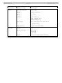
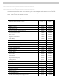
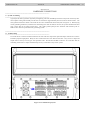
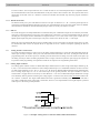
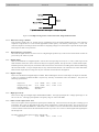
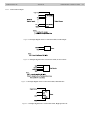
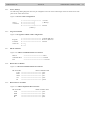
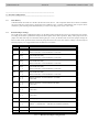


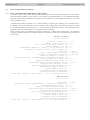
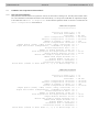

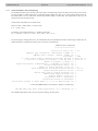
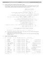
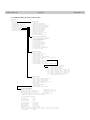


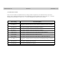
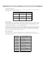
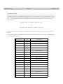
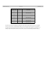
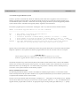
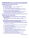


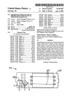


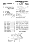


![hank yo_fo buyil_gaSamsung (}a_Te_a ]hs](http://vs1.manualzilla.com/store/data/005691502_1-2e8e29ffb67d0c8f7d0d701e3cb644b7-150x150.png)