1
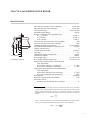
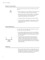
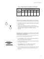
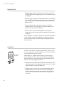
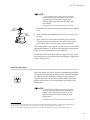
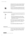
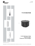
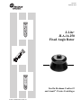
J-TB-072J
September 2008
J-Lite®
JLA-16.250
Fixed Angle Rotor
Used In Beckman Coulter J2
and Avanti® J Series Centrifuges
© 2008—2009 Beckman Coulter, Inc.
J-Lite® JLA-16.250 Rotor
!
SAFETY NOTICE
This safety notice summarizes information basic to the safe use of the rotor described in this manual.
The international symbol displayed above is a reminder to the user that all safety instructions should be
read and understood before operation or maintenance of this equipment is attempted. When you see the
symbol on other pages of this publication, pay special attention to the safety information presented.
Observance of safety precautions will also help to avoid actions that could damage or adversely affect
the performance of the rotor. This rotor was developed, manufactured, and tested for safety and
reliability as part of a Beckman Coulter centrifuge/rotor system. Its safety or reliability cannot be
assured if used in a non-Beckman Coulter centrifuge or in a Beckman Coulter centrifuge that has been
modified without Beckman Coulter’s approval.
!
!
!
2
Handle body fluids with care because they can transmit disease. No known test offers
complete assurance that such fluids are free of micro-organisms. Some of the most
virulent—Hepatitis (B and C) viruses, HIV (I–V), atypical mycobacteria, and certain
systemic fungi—further emphasize the need for aerosol protection. Handle other infectious
samples according to good laboratory procedures and methods to prevent spread of disease.
Because spills may generate aerosols, observe proper safety precautions for aerosol containment. Do not run toxic, pathogenic, or radioactive materials in this rotor without taking
appropriate safety precautions. Biosafe containment should be used when Risk Group II
materials (as identified in the World Health Organization Laboratory Biosafety Manual)
are handled; materials of a higher group require more than one level of protection.
The rotor and accessories are not designed for use with materials capable of developing
flammable or explosive vapors. Do not centrifuge such materials in nor handle or store them
near the centrifuge.
Although rotor components and accessories made by other manufacturers may fit in the
JLA-16.250 rotor, their safety in this rotor cannot be ascertained by Beckman Coulter. Use of
other manufacturers’ components or accessories in the JLA-16.250 rotor may void the rotor
warranty and should be prohibited by your laboratory safety officer. Only the components
and accessories listed in this publication should be used in this rotor.
!
Make sure that filled containers are loaded symmetrically into the rotor and that opposing
bottles or tubes are filled to the same level with liquid of the same density.
!
If disassembly reveals evidence of leakage, you should assume that some fluid escaped the
rotor. Apply all appropriate safety and decontamination procedures to the centrifuge and
accessories as required.
!
Never exceed the maximum rated speed of the rotor and labware in use. Refer to the section
on RUN SPEEDS.
!
Do not use sharp tools on the rotor that could cause scratches in the rotor surface. Corrosion
begins in scratches and may open fissures in the rotor with continued use.
J-Lite® JLA-16.250 FIXED ANGLE ROTOR
SPECIFICATIONS
25°
rmin
rav
rmax
Axis of Rotation
U.S. Patent No. 5,584,790
Maximum speed (Avanti® J series centrifuges) . . . . . . . . . . . . . 16 000 rpm
Maximum speed (J2 series centrifuges) . . . . . . . . . . . . . . . . . . . 14 000 rpm
Critical speed range* . . . . . . . . . . . . . . . . . . . . . . . . . . . . . . 600 to 800 rpm
Maximum solution density . . . . . . . . . . . . . . . . . . . . . . . . . . . . . . . 1.2 g/mL
Relative Centrifugal Field† at maximum speed
at rmax (134 mm) . . . . . . . . . . . . . . . . . . . . . . . . . . . . . . . . . 38 400 × g
at rav (90 mm) . . . . . . . . . . . . . . . . . . . . . . . . . . . . . . . . . . . 25 800 × g
at rmin (46 mm) . . . . . . . . . . . . . . . . . . . . . . . . . . . . . . . . . . 13 200 × g
k factor at max. speed in Avanti J series centrifuges. . . . . . . . . . . . . . . 1090
k factor at max. speed in J2 series centrifuges . . . . . . . . . . . . . . . . . . . 1400
Conditions requiring speed reduction . . . . . . . . . . . . . . . . see RUN SPEEDS
Maximum allowable imbalance of opposing loads. . . . . . . . . . . . . 10 grams
Number of bottle cavities . . . . . . . . . . . . . . . . . . . . . . . . . . . . . . . . . . . . . . 6
Available bottles and tubes . . . . . . . . . . . . . . . . . . . . . . . . . . . . . see Table 3
Tube angle . . . . . . . . . . . . . . . . . . . . . . . . . . . . . . . . . . . . . . . . . . . . . . . . 25°
Nominal tube capacity of largest tube. . . . . . . . . . . . . . . . . . . . . . . . 250 mL
Nominal rotor capacity . . . . . . . . . . . . . . . . . . . . . . . . . . . . . . . . . . 1500 mL
Rotor weight, empty . . . . . . . . . . . . . . . . . . . . . . . . . . . . . . 10.3 kg (22.7 lb)
Rotor weight, maximum sample mass . . . . . . . . . . . . . . . . 13.2 kg (29.1 lb)
Approximate acceleration time to maximum speed
(rotor fully loaded)
in an Avanti J centrifuge (to 16 000 rpm) . . . . . . . . . . . . . . . . 3 1/2 min
in a J2 series centrifuge (to 14 000 rpm) . . . . . . . . . . . . . . . . . 4 1/2 min
Approximate deceleration time from maximum speed
(rotor fully loaded)
in an Avanti J centrifuge (from 16 000 rpm) . . . . . . . . . . . . . . 2 3/4 min
in a J2 series centrifuge (from 14 000 rpm) . . . . . . . . . . . . . . . . . 4 min
Rotor material . . . . . . . . . . . . . . . . . . . . . . . . . . . . . . . . . . . . . . . . aluminum
Rotor entry code for Avanti J-E centrifuges . . . . . . . . . . . . . . . . . . . . . 16.25
Rotor entry code for
microprocessor-controlled J2 series centrifuges . . . . . . . . . . . . . . . . 14
*
The critical speed range is the range of speeds over which the rotor shifts so as to rotate about
its center of mass. Passing through the critical speed range is characterized by some vibration.
†
Relative Centrifugal Field (RCF) is the ratio of the centrifugal acceleration at a specified
radius and speed (rω 2) to the standard acceleration of gravity (g) according to the following
formula:
rω 2RCF = -------g
where r is the radius in millimeters, ω is the angular velocity in radians per second (2 π RPM /
60), and g is the standard acceleration of gravity (9807 mm/s2). After substitution:
RPM 2
RCF = 1.12 r ⎛⎝ ------------⎞⎠
1000
3
J-Lite® JLA-16.250 Rotor
DESCRIPTION
This rotor has been manufactured in a registered ISO 9001 or 13485
facility for use in Beckman Coulter Avanti® J and J2 series
centrifuges.
Lid
Small O-Ring
(893503)
Fluid
Containment
Annulus
Large
O-Ring
(893502)
Rotor
Body
The J-Lite® JLA-16.250 fixed angle rotor (see Figure 1), rated for
16 000 rpm in Beckman Coulter Avanti J series centrifuges and
14 000 rpm in Beckman Coulter J2 series centrifuges, is designed
to hold up to six 250-mL bottles at a 25-degree angle to the axis of
rotation. The JLA-16.250 rotor develops centrifugal forces that can
efficiently pellet cells from large volumes, or cell particles from tissue
homogenates. Short column methods (such as partially filled tubes)
may also be used to purify large quantities of virus in a cushion
gradient.
The rotor and lid are made of aluminum and are anodized for corrosion resistance—the rotor is black and the lid is blue. The tie-down
knob in the rotor lid secures the rotor to the centrifuge drive hub.
O-rings made of Buna N rubber, located in the rotor lid, help to maintain atmospheric pressure inside the rotor during centrifugation if the
O-rings are properly lubricated. Pins in the rotor drive hole mate with
grooves in the centrifuge drive hub (older model centrifuges), or with
drive hub teeth (newer model centrifuges), to prevent the rotor from
slipping during acceleration and deceleration.
Figure 1. The JLA-16.250 Fixed Angle Rotor (dual-locking lid shown)
4
J-Lite® JLA-16.250 Rotor
The dual-locking lid assembly allows the rotor to be loaded into and
removed from the centrifuge with the lid secured. The rotor may be
placed under a safety hood before the lid is secured or removed. The
JLA-16.250 rotor with dual-locking lid was tested1 to demonstrate
containment of microbiological aerosols under normal operating
conditions of the associated Beckman Coulter centrifuge, when used
and maintained as instructed. The rotor is also available with a singlelocking lid.
The JLA-16.250 rotor has a patented fluid-containment annulus,
located below the O-ring sealing surface. This feature helps to
prevent the escape of liquid into the centrifuge chamber if tubes or
bottles leak during centrifugation.
The JLA-16.250 rotor is warranted for 7 years (see the WARRANTY).
PREPARATION AND USE
Specific information about the JLA-16.250 rotor is given here. Use
the Rotors and Tubes for J Series Centrifuges manual (publication
JR-IM), and the centrifuge instruction manual along with this manual
for complete rotor and accessory information.
➠
1
NOTE
Although rotor components and accessories
made by other manufacturers may fit in the
JLA-16.250 rotor, their safety in this rotor
cannot be ascertained by Beckman Coulter.
Use of other manufacturers’ components in the
JLA-16.250 rotor may void the rotor warranty
and should be prohibited by your laboratory
safety officer. Only the components and
accessories listed in this publication should be
used in this rotor.
Validation of microbiological containment was done at an independent third-party testing facility (CAMR, Porton Down, UK, or USAMRIID,
Ft. Detrick, MD, U.S.A.). Improper use or maintenance may affect seal integrity and thus containment.
5
J-Lite® JLA-16.250 Rotor
PRERUN SAFETY CHECKS
Read the SAFETY NOTICE at the front of this manual before using
the rotor.
1. Make sure that the rotor, lid, and all tubes or bottles and accessories are clean and show no signs of corrosion or cracking.
2. Inspect the rotor drive pins to ensure that they are not damaged
(see instructions on page 19). If the drive pins appear to be
damaged, contact Beckman Coulter Field Service.
3. Verify that the bottles or tubes being used are listed in Table 3.
4. Check the chemical compatibilities of all materials used. (Refer
to Appendix A in Rotors and Tubes, or Chemical Resistances,
publication IN-175).
ROTOR PREPARATION
For runs at other than room temperature, refrigerate or warm the
rotor before the run for fast equilibration.
1. Be sure that the metal threads in the rotor are clean and lightly
lubricated with Spinkote™ lubricant (306812). Also ensure that
lid O-rings are lightly but evenly coated with silicone vacuum
grease (335148).
2. Load filled containers symmetrically into the rotor. (Refer
to BOTTLES AND TUBES on page 14 for information about
containers.) If fewer than six bottles or tubes are being run,
they must be arranged symmetrically in the rotor (see Figure 2).
Opposing containers must be filled to the same level with liquid
of the same density.
OPERATION
• Precool the rotor in the centrifuge or in a refrigerator before use—
especially before short runs—to ensure that the rotor reaches the
set temperature. A suggested precooling cycle is a minimum of
30 minutes at 2000 rpm at the required temperature.
6
J-Lite® JLA-16.250 Rotor
Figure 2. Typical Examples of Arranging Bottles or Tubes in the Rotor.
Two, three, four, or six containers can be centrifuged per run,
if they are arranged in the rotor as shown.
• If fluid containment is required, use capped bottles or tubes. It is
strongly recommended that all containers carrying physiological
fluids be capped, and not overfilled, to prevent leakage.
• If you are using an Avanti J series centrifuge, select the
JLA-16.250 rotor.
• If you are using a microprocessor-controlled J2 series centrifuge,
enter rotor code 14. Refer to your centrifuge instruction manual
for additional information. See BEFORE USING THE JLA-16.250
ROTOR IN A MICROPROCESSOR-CONTROLLED J2 SERIES
CENTRIFUGE, below, if you are using the rotor for the first time.
BEFORE USING THE JLA-l6.250 ROTOR IN A MICROPROCESSOR-CONTROLLED
J2 SERIES CENTRIFUGE
If you have a microprocessor-controlled Beckman Coulter J2 series
centrifuge (model J2-MI, J2-21M, J2-21M/E, or J2-MC), you will
need to enter the JLA-16.250 rotor identification code (14) and
maximum speed (l4 000 rpm) into the instrument memory before the
first use of the JLA-16.250 rotor in that instrument. Use the following
instructions.
1. On the centrifuge panel, press and hold the [ROTOR] key. While
holding [ROTOR], press [PROG SAVE]. Release both keys. The rotor
display area will show 1 – – . – . This indicates that you are ready
to program the first entry, which is the rotor identification code 14.
Enter 14, again press and hold the [ROTOR] key, press [PROG SAVE],
and then release both keys.
7
J-Lite® JLA-16.250 Rotor
2. The rotor display should now show 2 – – . – . You are now ready
to program the second entry, the JLA-16.250 rotor’s maximum
speed in J2 series centrifuges, which is l4 000 rpm. Enter 14, again
press and hold [ROTOR], press [PROG SAVE], and release both keys.
3. The rotor display should now show 3 – – . – . The third entry
programs the temperature compensation for the rotor. It is not
possible, however, to enter a compensation value at this step; you
must enter 0. Entering temperature compensation is discussed
below (see TEMPERATURE) since it is programmed differently
and can be entered only after these three steps have been
completed.
4. To complete the entries, press and hold [ROTOR], then press
[ENTER/RECALL], then release both keys. The display should now
return to normal.
If you make an error, or if you wish to review the entered information
press both [ROTOR] and [PROG SAVE] repeatedly to cycle through
levels 1, 2, and 3. The program can only be logged into memory from
level 3, and only when all three entries are complete.
Once this procedure is complete, the microprocessor memory will
retain the information and it will not have to be entered again. Each
time you run the JLA-16.250 rotor, enter code 14 as described in the
centrifuge instruction manual.
INSTALLING THE ROTOR
Tie-down Knob
Daisy
Knob
Knob Threads
Dual-Locking Lid
1. To prevent the rotor from sticking to the centrifuge drive hub,
apply a thin coat of Spinkote lubricant to the rotor drive pins and
to the lid knob threads.
2. Lightly coat the large and small lid O-rings with silicone vacuum
grease.
3. Dual-locking lid only. Place filled tubes into the rotor, then place
the lid on the rotor and turn the daisy knob to the right (clockwise)
until secure. Do not overtighten.
4. Two v-shaped indicator marks on either side of the rotor drive hole
(see Figure 3) indicate orientation of the rotor drive pins, which
are located in the drive hole. To avoid damaging the drive pins as
you install the rotor, use the indicator marks to help you align the
pins with the centrifuge drive spindle hub.
8
J-Lite® JLA-16.250 Rotor
Tie-down Knob
Knob Threads
5. Once the rotor is properly aligned carefully lower it straight down
onto the hub. Do not drop the rotor onto the hub.
6. Slowly turn the rotor around the drive spindle to make sure that it
is properly seated. In rare cases, the rotor pins can rest on top of
the spindle hub pins or teeth, which prevents the rotor from being
secured to the drive spindle. Turning the rotor after installing it
will move the pins into proper position.
Single-Locking Lid
Indicator Marks
Figure 3. Rotor Top View: Indicator Marks Show Drive Pin Orientation
7. Secure the rotor to the centrifuge drive spindle as follows:
Dual-locking lid: press the lid knob down and turn it to the right
(clockwise) until secure, no more than two full turns. Do not
overtighten.
Single-locking lid: place filled tubes into the rotor, then place the
lid on the rotor. Press the lid knob down and turn it to the right
(clockwise) until secure. Do not overtighten.
!
WARNING
If the rotor is left in the centrifuge between
runs, make sure that the rotor is seated on the
drive hub and that the tie-down knob is tight
before each run.
9
J-Lite® JLA-16.250 Rotor
TEMPERATURE
To ensure that the JLA-16.250 rotor reaches the required temperature
during the run, follow the appropriate instructions below for the
J centrifuge model being used.
Avanti J Series Centrifuges
Enter the run temperature according to the instructions in your centrifuge instruction manual. No additional input is required.
J2 Series Centrifuges
Enter the required run temperature and the appropriate temperature
compensation units (see Tables 1 and 2) on the centrifuge control
panel following the instructions below.
Table 1. Temperature Compensation Settings for Analog
and Microprocessor-Controlled Centrifuges (Models J2-HS,
J2-21, J2-MI, J2-21M, J2-MC, and J2-21M/E).
Interpolate if intermediate values are required.
Required Sample Temperature (°C)
Rotor
Speed
(rpm)
–10
2
5
10
20
40
14 000
N
–7
–5
–4
–3
–3
10 000
–4
–3
–3
–2
–1
N
5 000
0
0
0
0
0
N
“N” indicates that the rotor cannot achieve the required temperature at this speed.
10
J-Lite® JLA-16.250 Rotor
Table 2. Temperature Compensation Settings for the Model J2-HC
Analog Centrifuge. Interpolate if intermediate values are required.
Required Sample Temperature (°C)
Rotor
Speed
(rpm)
–10
2
5
10
20
40
14 000
N
–7
–7
–7
–5
–4
10 000
–4
–3
–3
–2
–1
N
5 000
0
0
–3
–3
–3
N
“N” indicates that the rotor cannot achieve the required temperature at this speed.
Analog J2 Series Centrifuges (Models J2-HS, J2-21, and J2-HC)
1. Turn the SET knob on the centrifuge control panel to the required
sample temperature.
2. Find the compensation value in Table 1 or Table 2 that corresponds to the required temperature and run speed. Set the COMP
dial to that setting. (Interpolate if intermediate values are
required.)
Microprocessor-Controlled J2 Series Centrifuges (Models J2-MI,
J2-21M, J2-MC, and J2-21M/E)
Enter rotor code 14, then follow the steps below.
1. Press the [TEMP] key on the centrifuge control panel and then use
the keypad to enter the sample temperature.
2. Find the compensation value in Table 1 that corresponds with the
set temperature and run speed.
3. Press [COMP ADJ]. The word “COMP” flashes below the
TEMPERATURE display and the display flashes.
4. Use the keypad to enter the desired compensation value. Press the
[±.] key to enter a minus sign; pressing it again will remove the
minus sign.
11
J-Lite® JLA-16.250 Rotor
5. Check the temperature display. (If the entry is incorrect, press [CE]
and reenter the digits.)
6. When the entry is correct, press [ENTER/RECALL].
➠
NOTE
To clear a COMP ADJ entry, press [COMP ADJ],
[0], and [ENTER/RECALL].
RUN PROCEDURE
!
WARNING
Operator error or tube failure may generate
aerosols. Toxic, pathogenic, or other
hazardous materials must not be run in
this rotor unless all appropriate safety
precautions are taken. Also see the Safety
Notice at the beginning of this manual.
!
CAUTION
Make sure that the rotor is properly seated on
and securely fastened to the drive hub before
each run.
When the rotor is properly loaded and installed in the centrifuge,
you are ready to perform the run. Refer to the applicable centrifuge
instruction manual for operating instructions.
➠
12
NOTE
Line voltage fluctuations can cause variations in
acceleration and deceleration times.
J-Lite® JLA-16.250 Rotor
REMOVAL AND SAMPLE RECOVERY
!
CAUTION
If disassembly reveals evidence of leakage, you
should assume that some fluid escaped the rotor.
Apply appropriate decontamination procedures
to the centrifuge and accessories, as required.
Dual-Locking Lid
1. Place one hand on the rotor to keep it from turning. Grasp the
tie-down knob with your other hand and turn it to the left (counterclockwise), while pulling up, until the stem disengages from the
drive hub.
2. Place your hands on the rotor and lift the rotor straight up off the
drive hub. Do not lift the rotor by the tie-down knob.
3. Place the rotor on a counter or bench top under a safety hood
(if required).
4. Grasp the daisy knob and turn it to the left (counterclockwise)
until it disengages.
5. Remove the lid and set it aside. If the lid cannot be removed, first
pull up on the tie-down knob to release vacuum inside the rotor,
and then remove the lid.
!
CAUTION
Always loosen the round tie-down knob to
disengage the rotor from the centrifuge drive
hub before attempting to loosen the daisy knob.
The dual-locking lid assembly can be damaged if
the daisy knob is loosened while the rotor is still
engaged with the hub.
13
J-Lite® JLA-16.250 Rotor
Single-Locking Lid
1. Unscrew the tie-down knob to release the rotor from the drive hub.
2. Remove the lid and set it aside.
3. Lift the rotor straight up off the drive hub. Do not lift the rotor by
the tie-down knob.
➠
NOTE
Lubricating the centrifuge drive hub with
Spinkote should prevent the rotor from sticking
in J2 series centrifuges. In Avanti J series centrifuges, the drive hubs do not need lubrication
because Delrin rings on the hubs prevent
sticking.
BOTTLES AND TUBES
The JLA-16.250 rotor uses the bottles and tubes listed in Table 3.
Be sure to use only those items listed and observe the maximum
fill volumes and speed limits shown. (Maximum fill volume is the
maximum amount of fluid that can be centrifuged in the listed
container.) To minimize the possibility of leakage from capped tubes
or bottles, load tubes or bottles with sample, secure the caps, and
precool the loaded, sealed labware to run temperature before
beginning the run.
Refer to Appendix A in Rotors and Tubes for information on the
chemical resistances of tube and accessory materials.
Temperature Limits
• Plastic containers have been tested for use at temperatures between
2 and 25°C. For centrifugation at other temperatures, pretest
containers under anticipated run conditions.
• If plastic containers are frozen before use, make sure that they are
thawed to at least 2°C before centrifugation.
14
J-Lite® JLA-16.250 Rotor
Table 3. Available Bottles and Tubes for the JLA-16.250 Rotor.
Use only the items listed here and observe fill volumes and maximum run speeds.
Required Accessory
Dimensions
and Volume
Tube
Description
Part
Number
Max.
Fill
Volume
(mL)
62 × 120 mm
250 mL
polypropylene bottle
w/cap assembly
356011
250
none
16 000 rpm
38 500 × g
1 070
62 × 120 mm
250 mL
polycarbonate bottle
w/cap assembly
356013
250
none
16 000 rpm
38 500 × g
1 090
29 × 104 mm
50 mL
polyallomer bottle
w/cap assembly
357001
40
adapter
356997b
1
16 000 rpm
32 200 × g
650
29 × 104 mm
50 mL
polycarbonate bottle
w/cap assembly
357000
40
adapter
356997
1
16 000 rpm
32 400 × g
660
29 × 104 mm
50 mL
polycarbonate bottle,
screw-on cap
357002
38.5
adapter
356997
1
16 000 rpm
32 200 × g
660
29 × 104 mm
50 mL
polyallomer bottle,
screw-on cap
357003
38.5
adapter
356997
1
16 000 rpm
32 200 × g
650
29 × 104 mm
50 mL
thickwall polycarbonate,
snap-on cap
363664
36
adapter
356997
1
16 000 rpm
32 100 × g
400
29 × 104 mm
50 mL
thickwall polypropylene,
snap-on cap
357005
36
adapter
356997
1
16 000 rpm
32 100 × g
400
17 × 119 mm
15 mL
conical tube
c
15
adapter
356964b
4
c
Bio-vials
4 mL
polypropylene
566353
4
adapter
342098d
9
4 000 rpm
2 300 × g
10 700
Description
Part
Number
Tubes
per
Adapter
Max
Speeda/
RCF/
k Factor
a
Maximum speeds listed are guidelines only. These speeds have been achieved in reliability tests at Beckman Coulter, but because of manufacturing
variances no guarantee of performance or fit is expressed or implied. (The maximum rotor speed in J2 series centrifuges is 14 000 rpm.)
b
Polypropylene.
c
Commercially available. Observe manufacturer’s maximum speed and fill guidelines.
d
Delrin. Delrin is a registered trademark of E.I. DuPont de Nemours & Company.
15
J-Lite® JLA-16.250 Rotor
Thickwall Tubes
Thickwall polyallomer, polypropylene, and polycarbonate tubes can
be run partially filled (at least half filled) with or without caps, but all
opposing tubes for a run must be filled to the same level with liquid of
the same density. Do not overfill capless tubes; be sure to note the fill
volumes and run speeds shown in Table 3.
Polycarbonate and Polyallomer Bottles
Capped polycarbonate and polyallomer bottles may be centrifuged
completely or partially filled (not less than half full). Again, all
opposing containers for a run must be filled to the same level.
RUN TIMES
The k factor is a measure of a rotor’s pelleting efficiency. Beckman
Coulter has calculated the k factor for all of its rotors, at maximum
speed with full bottles or tubes, using the following formula:
ln ( rmax ⁄ rmin ) 10 13
k = ------------------------------------- × -----------3600
ω2
(1)
Where ω is the angular velocity of the rotor in radians per second
(ω = 0.105 × rpm), rmax is the maximum radius, and rmin is the
minimum radius.
After substitution:
(2.533 × 10 11) ln ( rmax ⁄ rmin )
k = ------------------------------------------------------------------------rpm 2
(2)
Use the k factor in the following equation to estimate the run time t
(in hours) required to pellet particles of known sedimentation coefficient s (in Svedberg units, S).
16
J-Lite® JLA-16.250 Rotor
k
t = -s
(3)
For centrifugation below maximum speed, estimate the run time
required by adjusting the k factor as follows:
maximum speed 2
k adj = k ⎛----------------------------------------- ⎞
⎝ actual run speed ⎠
(4)
Run times can also be estimated from data established in prior
experiments using a different rotor if the k factor of the previous rotor
is known. For any two rotors, a and b:
ka
ta
----= -----tb
kb
(5)
Where the k factors have been adjusted for the actual run speed used.
For more information on k factors, see Use of k Factor for
Estimating Run Times from Previously Established Run Conditions
(publication DS-719).
RUN SPEEDS
SPEED
The centrifugal force at a given radius in a rotor is a function of
run speed. Comparisons of forces between different rotors are made
by comparing the rotors’ relative centrifugal fields (RCF). When
rotational speed is adjusted so that identical samples are subjected
to the same RCF in two different rotors, the samples are subjected
to the same force. The RCF at a number of rotor speeds is provided
in Table 4.
17
J-Lite® JLA-16.250 Rotor
Table 4. Relative Centrifugal Fields for the JLA-16.250 Rotor.
Entries in this table are calculated from the formula
RCF = 1.12r (RPM/1000)2
and are then rounded to three significant digits.
Relative Centrifugal Field (× g)
Rotor
Speed
(rpm)
at rmax
(134 mm)
at rav
(90 mm)
at rmin
(46 mm)
16 000
15 000
14 000
13 000
12 000
38 400
33 800
29 400
25 400
21 600
25 800
22 700
19 800
17 000
14 500
13 200
11 600
10 100
8 710
7 420
11 000
10 000
9 000
8 000
18 200
15 000
12 200
9 610
12 200
10 100
8 160
6 450
6 230
5 150
4 170
3 300
7 000
6 000
5 000
4 000
7 350
5 400
3 750
2 400
4 940
3 630
2 520
1 610
2 520
1 860
1 290
824
3 000
2 000
1 000
500
1 350
600
150
38
907
403
100
25
464
206
52
13
Relative Centrifugal Fields for the JLA-16.250 Rotor
40 000
35 000
RCF (x g)
30 000
25 000
rmax
20 000
rav
rmin
15 000
10 000
5 000
0
0
2 000
4 000
6 000
8 000
Speed (rpm)
18
10 000
12 000
14 000
16 000
J-Lite® JLA-16.250 Rotor
Do not select rotational speeds higher than the maximums you have
determined to be appropriate for your protocols (in no case above
16 000 rpm in an Avanti J series centrifuge or 14 000 rpm in a
J2 series centrifuge, or above the limit shown in Table 3). When
solutions more dense than 1.2 g/mL are centrifuged in this rotor, use
equation (6) to calculate the reduced maximum allowable speed in
Avanti J series centrifuges. Use equation (7) to calculate the reduced
maximum allowable speed in J2 series centrifuges.
reduced maximum speed = (16 000 rpm)
1.2 g/mL
--------------------------------------------------------density of tube contents
(6)
reduced maximum speed = (14 000 rpm)
1.2 g/mL
--------------------------------------------------------density of tube contents
(7)
Note, however, that the use of this formula may still produce
maximum speed figures higher than the limitations imposed by the
use of certain tubes or adapters (see Table 3). In such cases, use the
lower of the two figures.
CARE AND MAINTENANCE
INSPECTION
Check
for
Corrosion
Periodically (at least monthly) inspect the rotor body for rough spots
or pitting, white powder deposits—frequently aluminum oxide—or
heavy discoloration. If any of these signs are evident, do not use the
rotor. Contact your Beckman Coulter representative for information
about the Field Rotor Inspection Program (FRIP) and the rotor
repair center.
Rotor
Body
Before using the rotor, inspect the rotor drive pins to ensure that they
are not damaged. Damaged drive pins can prevent the rotor from
seating properly on the centrifuge drive hub (Avanti J series centrifuges only). To inspect the drive pins, turn the rotor upside down and
look into the drive hole in the center of the rotor. If the drive pins
appear damaged, contact Beckman Coulter Field Service.
19
J-Lite® JLA-16.250 Rotor
MAINTENANCE
• Regularly apply silicone vacuum grease to the large and small
O-rings. Replace the O-rings about twice a year, or whenever worn
or damaged.
• Routinely apply a light coat of Spinkote lubricant to the centrifuge
drive hub (J2 series centrifuges only) and to the rotor drive hole
to prevent the rotor from sticking. Lubricate the lid knob threads
before each use.
• Do not use sharp tools on the rotor, as they can scratch the
anodized surface. Corrosion begins in scratches and may open
fissures in the metal with continued use.
• Do not store the rotor with the lid tightened. The constant
compression on the O-rings caused by a tightened lid may reduce
O-ring life.
Refer to Appendix A in Rotors and Tubes for the chemical resistances
of rotor and tube materials. Your Beckman Coulter representative
provides contact with the Field Rotor Inspection Program and the
rotor repair center.
CLEANING
Wash the rotor and rotor components immediately if salts or other
corrosive materials are used or if spillage has occurred. Do not allow
corrosive materials to dry on the rotor.
Rotor Cleaning
Kit (339558)
Under normal use, wash the rotor frequently (at least weekly) to
prevent buildup of residues. If the rotor is left in the centrifuge for
long periods of time, remove the rotor from the centrifuge at least
once a month for cleaning and lubrication.
1. Remove the O-rings from the rotor lid before cleaning. (To avoid
scratching the rotor or damaging the O-rings, remove the O-rings
using a toothpick or other non-metal tool.)
2. Wash the rotor, lid, and O-rings using a mild detergent, such as
Beckman Solution 555™ (339555). The Rotor Cleaning Kit
(339558) contains two brushes and two quarts of Solution 555
for use with rotors and accessories. Dilute the detergent 10 to 1
with water.
20
J-Lite® JLA-16.250 Rotor
➠
Small
O-Ring
(893503)
NOTE
Do not wash the rotor components or accessories
in a dishwasher. Do not soak components in
detergent solution for long periods of time, such
as overnight.
3. Thoroughly rinse the cleaned rotor and components with distilled
water.
Large
O-Ring
(893502)
4. Air-dry the rotor and lid upside down. Do not use acetone to dry
the rotor.
5. Apply a thin, even coat of silicone vacuum grease to the lid
O-rings and replace them in the grooves in the lid. Be careful
not to stretch, roll, or twist the O-rings during installation.
Clean metal threads every 6 months, or as necessary. Use a brush and
concentrated Solution 555. Rinse and dry thoroughly, then lubricate
lightly but evenly with Spinkote to coat all threads.
Periodically remove the O-rings and wipe clean as necessary. Clean
the O-ring grooves with a cotton-tipped swab. Reapply a light film of
silicone vacuum grease.
DECONTAMINATION
If the rotor (and/or accessories) becomes contaminated with radioactive material, decontaminate it using a solution that will not damage
the anodized surfaces. Beckman Coulter has tested a number of
solutions and found several that do not harm anodized aluminum:
RadCon Surface Spray or IsoClean Solution (for soaking),2 and
Radiacwash.3
➠
NOTE
IsoClean can cause fading of colored anodized
surfaces, such as the blue rotor lid. Use it only
when necessary and remove it promptly from
rotor surfaces.
2
In U.S.A., contact Nuclear Associates (New York); in Eastern Europe and Commonwealth States, contact Victoreen GmbH (Munich);
in South Pacific, contact Gammasonics Pty, Ltd. (Australia); in Japan, contact Toyo Medic Co. Ltd. (Tokyo).
3
In U.S.A., contact Biodex Medical Systems (Shirley, NY); internationally, contact the U.S. office to find the dealer nearest you.
21
J-Lite® JLA-16.250 Rotor
While Beckman Coulter has tested these methods and found that they
do not damage the rotor or components, no guarantee of sterility or
disinfection is expressed or implied. When sterilization or disinfection is a concern, consult your laboratory safety officer regarding
proper methods to use.
If the rotor or other components are contaminated with toxic or pathogenic materials, follow appropriate decontamination procedures as
outlined by your laboratory safety officer. Refer to Rotors and Tubes
to evaluate your rotor’s ability to withstand a given chemical solution.
STERILIZATION AND DISINFECTION
• The rotor and all rotor components can be autoclaved at 121°C for
up to one hour. Place the rotor in the autoclave upside down, with
the lid removed.
• Ethanol (70%)4 or hydrogen peroxide (6%) may be used on
all rotor components, including those made of plastic. Bleach
(sodium hypochlorite) may be used, but may cause discoloration
of anodized surfaces. Use the minimum immersion time for each
solution, per laboratory standards.
While Beckman Coulter has tested these methods and found that
they do not damage components, no guarantee of sterility or disinfection is expressed or implied. When sterilization or disinfection is a
concern, consult your laboratory safety officer regarding proper
methods to use.
Refer to publication IN-192, included in each box of tubes or bottles,
for tube and bottle sterilization and disinfection procedures.
TUBE BREAKAGE
If a glass bottle or tube breaks, remove the glass very carefully from
the rotor and/or adapter. Imbedded glass particles that remain in the
rotor cavities or adapters can cause tube failure during subsequent
runs. Clean the rotor thoroughly immediately following a bottle or
tube breakage.
4
22
Flammability hazard. Do not use in or near operating centrifuges.
J-Lite® JLA-16.250 Rotor
STORAGE
When the rotor is not in use, store it in a dry environment (not in the
centrifuge) with the lid removed to allow air circulation so moisture
will not collect in the tube cavities.
RETURNING A ROTOR
RGA
Before returning a rotor or accessory for any reason, prior permission
(a Returned Goods Authorization form) must be obtained from
Beckman Coulter, Inc. This RGA form, which may be obtained from
your local Beckman Coulter sales office, should contain the following
information:
• rotor serial number,
• history of use (approximate frequency of use),
• reason for the return,
• original purchase order number, billing number, and shipping
number, if possible,
• name and phone number of the person to be notified upon receipt
of the rotor or accessory at the factory, and
• name and phone number of the person to be notified about repair
costs, etc.
To protect our personnel, it is the customer’s responsibility to ensure
that the parts are free from pathogens and/or radioactivity. Sterilization and decontamination must be done before returning the parts.
Smaller items (such as tubes, bottles, etc.) should be enclosed in a
sealed plastic bag.
All parts must be accompanied by a note, plainly visible on the outside of the box or bag, stating that they are safe to handle and that
they are not contaminated with pathogens or radioactivity. Failure to
attach this notification will result in return or disposal of the items
without review of the reported problem.
Use the address label printed on the RGA form when mailing the
rotor and/or accessories.
Customers located outside the United States should contact their local
Beckman Coulter office.
23
J-Lite® JLA-16.250 Rotor
SUPPLY LIST
Call Beckman Coulter Sales (1-800-742-2345 in the United States) or
your local Beckman Coulter office, or see the Beckman Coulter High
Performance, High Speed, High Capacity Rotors, Tubes & Accessories catalog (BR-8102, available at www.beckmancoulter.com) for
detailed information on ordering parts and supplies. For your convenience, a partial list is given below.
➠
NOTE
Publications referenced in this document can be
obtained by calling Beckman Coulter at 1-800742-2345 in the United States, or by contacting
your local Beckman Coulter office.
REPLACEMENT ROTOR PARTS
JLA-16.250 rotor assembly, biosafe (with dual-locking lid) . . . . . .
JLA-16.250 rotor assembly (with single-locking lid) . . . . . . . . . . . .
Dual-locking lid assembly. . . . . . . . . . . . . . . . . . . . . . . . . . . . . . . . .
Single-locking lid assembly . . . . . . . . . . . . . . . . . . . . . . . . . . . . . . .
Large lid O-ring (qty/2). . . . . . . . . . . . . . . . . . . . . . . . . . . . . . . . . . .
Small lid O-ring (qty/2). . . . . . . . . . . . . . . . . . . . . . . . . . . . . . . . . . .
363930
363934
363931
363935
893502
893503
SUPPLIES
Bottles, tubes, and adapters . . . . . . . . . . . . . . . . . . . . . . . . . . . . . see Table 3
Rotor Cleaning Kit . . . . . . . . . . . . . . . . . . . . . . . . . . . . . . . . . . . . . . 339558
Silicone vacuum grease (1 oz) . . . . . . . . . . . . . . . . . . . . . . . . . . . . . 335148
Solution 555 (1 qt). . . . . . . . . . . . . . . . . . . . . . . . . . . . . . . . . . . . . . . 339555
Spinkote lubricant (2 oz) . . . . . . . . . . . . . . . . . . . . . . . . . . . . . . . . . . 306812
24
J SERIES ROTOR WARRANTY
Subject to the conditions specified below and the warranty
clause of the Beckman Coulter, Inc., terms and conditions of
sale in effect at the time of sale, Beckman Coulter, Inc. agrees
to correct either by repair, or, at its election, by replacement,
any defects of material or workmanship which develop within
seven (7) years after delivery of a J series rotor to the original
buyer by Beckman Coulter, Inc. or by an authorized representative, provided that investigation and factory inspection by
Beckman Coulter, Inc. discloses that such defect developed
under normal and proper use. Should a Beckman Coulter centrifuge be damaged due to a failure of a rotor covered by this
warranty, Beckman Coulter will supply free of charge all centrifuge parts required for repair.
REPLACEMENT
Any product claimed to be defective must, if requested by
Beckman Coulter, Inc., be returned to the factory, transportation charges prepaid, and will be returned to Buyer with the
transportation charges collect unless the product is found to be
defective, in which case Beckman Coulter, Inc. will pay all
transportation charges.
A defective rotor will be replaced by Beckman Coulter, Inc. at
its then current list price less a credit based upon the age of the
rotor (years since date of purchase). The Buyer shall not
receive credit until the claimed defective rotor is returned to
Beckman Coulter’s Indianapolis, Indiana facility or delivered
to a Beckman Field Service representative.
The replacement price (cost to Buyer) for the respective rotor
shall be calculated as follows:
years
7
Replacement price = Current rotor list price × ------------
CONDITIONS
1. Except as otherwise specifically provided herein, this warranty covers the rotor only and Beckman Coulter, Inc.
shall not be liable for damage to accessories or ancillary
supplies including but not limited to (i) tubes, (ii) tube
caps, (iii) tube adapters, or (iv) tube contents.
2. This warranty is void if the rotor has been subjected to
customer misuse such as operation or maintenance contrary to the instructions in the Beckman Coulter rotor or
centrifuge manual.
3. This warranty is void if the rotor is operated with a rotor
drive unit or in a centrifuge unmatched to the rotor characteristics, or is operated in a Beckman Coulter centrifuge
that has been improperly disassembled, repaired, or
modified.
DISCLAIMER
IT IS EXPRESSLY AGREED THAT THE ABOVE WARRANTY SHALL BE IN LIEU OF ALL WARRANTIES OF
FITNESS AND OF THE WARRANTY OF MERCHANTABILITY AND THAT BECKMAN COULTER, INC.
SHALL HAVE NO LIABILITY FOR SPECIAL OR CONSEQUENTIAL DAMAGES OF ANY KIND WHATSOEVER ARISING OUT OF THE MANUFACTURE, USE,
SALE, HANDLING, REPAIR, MAINTENANCE, OR
REPLACEMENT OF THE PRODUCT.
Beckman Coulter, Inc. • 250 S. Kraemer Blvd. • Brea, California 92821
Sales and Service: 1-800-742-2345 • Internet: www.beckmancoulter.com
©2009 Beckman Coulter, Inc.
All rights reserved