1
Door Fan 3.0
Software User’s Manual
Copyright © 2003, 2004, 2005, 2006, 2007 Retrotec Energy Innovations Ltd
All rights reserved.
This document contains materials protected under International Copyright Laws. All rights reserved. No part of
this document may be copied or reproduced in any form or by any means without the prior written consent of
Retrotec Energy Innovations Ltd.
Retrotec makes no warranties with respect to this documentation and disclaims any implied warranties of
merchantability, quality, or fitness for any particular purpose. The information in this document is subject to
change without notice. Retrotec reserves the right to make revisions to this publication without obligation to
notify any person or entity of any such changes.
D
F
i
Door Fan 3.0 Software Users Manual
Table of Contents
1
SOFTWARE INSTALLATION............................................................................ 2
2
USING A DM-2A WITH DOOR FAN 3.0............................................................... 3
2.1
2.2
2.3
3
Installing the DM-2A Drivers on Your USB Ports ..................................................................................................3
Identifying where the DM-2 Drivers are Located ....................................................................................................3
Completing the DM-2 Driver Installation ................................................................................................................4
INSTALLING THE SOFTWARE LICENSE ...............................ERROR! BOOKMARK NOT DEFINED.
3.1
3.2
4
Importing your Certificate........................................................................................................................................9
Using your Software Certificate.............................................................................................................................10
PRETEST BUILDING SETUP .......................................................................... 11
4.1
4.2
4.3
5
Group/Customer Setup...........................................................................................................................................11
Building Setup........................................................................................................................................................11
Zone Setup .............................................................................................................................................................12
CONDUCTING A MANUAL TEST ...................................................................... 13
5.1
5.2
5.3
5.4
5.5
5.6
5.7
5.8
5.9
5.10
5.11
5.12
6
Direction.................................................................................................................................................................13
Operator .................................................................................................................................................................13
Static Pressure ........................................................................................................................................................14
Temperature ...........................................................................................................................................................14
Test Section............................................................................................................................................................14
Number of Points ...................................................................................................................................................14
Range Selection......................................................................................................................................................15
Room Pressure .......................................................................................................................................................15
Flow Pressure .........................................................................................................................................................15
Corrected Flow.......................................................................................................................................................15
Error % ...................................................................................................................................................................16
Calculate Results ....................................................................................................................................................16
CONDUCTING AN AUTO TEST ....................................................................... 17
6.1
6.2
6.3
6.4
6.5
6.6
6.7
6.8
6.9
Pressure Settings ....................................................................................................................................................17
Direction.................................................................................................................................................................17
Operator .................................................................................................................................................................18
Temperature ...........................................................................................................................................................18
Range Selection......................................................................................................................................................18
Starting the Auto Test ............................................................................................................................................18
Auto Static Pressure ...............................................................................................................................................18
Monitoring Auto Test.............................................................................................................................................19
Completing Auto test .............................................................................................................................................19
7
RESULTS ........................................................................................... 20
8
REPORTS ........................................................................................... 21
9
RANGE SELECTION .................................................................................. 22
10
TROUBLESHOOTING ................................................................................. 24
Page 1 of 25
m:\projects\manuals\Door Fan 3.0\Door Fan 3.0 User’s Manual.doc
Door Fan 3.0 Software Users Manual
1 Software Installation
It is recommended that you use Windows XP with Service pack 2 installed.
Door Fan 3.0 is constantly under development and new features are being continuously
added. Released versions of the software can be downloaded from our website at
http://www.retrotec.com/products/software/door_fan_30
Download the latest version and run the executable file. You must accept the license
agreement before you can install the software.
Once the software is installed you can access it by going to Start -> Programs -> Retrotec
Programs -> Door Fan 3.0 or you can use the Desktop Icon if you chose to create one on your
desktop.
Page 2 of 25
Door Fan 3.0 Software Users Manual
2 Using a DM-2A with Door Fan 3.0
Door Fan 3.0 can be used stand alone or can be completely integrated with your fan system
by using a Retrotec DM-2A Digital Gauge.
Note: The following procedure must be repeated for every USB port on your computer.
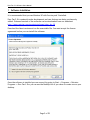
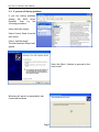
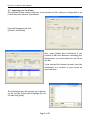
2.1 Installing the DM-2A Drivers on Your USB Ports
Connect your DM-2A to your PC using a
standard USB Cable. The following window
should appear.
Select “No, not this time” and press [Next >]
to proceed with manual identification of the
location of the DM-2 drivers
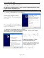
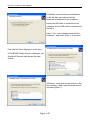
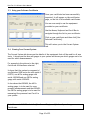
2.2 Identifying where the DM-2 Drivers are Located
Windows does not know where the DM-2 drivers are located. You must remind Windows
where the drivers are located for each USB port.
During the software installation, the DM-2
drivers are copied into the USB sub-folder in
the folder in which you installed the Door
Fan 3.0 software.
By default this location is C:\Program
Files\Retrotec\DM2 Drivers\USB\
If presented with the option, decline the
automatic installation and instead, choose
to install from a specific location.
Press [Next >] to proceed.
Page 3 of 25
Door Fan 3.0 Software Users Manual
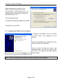
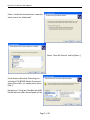
When asked where to search for the
drivers, select to only search in the
provided folder, and then [Browse] to the
USB sub-folder of the folder in which you
installed Door Fan 3.0
This would typically be
C:\Program Files\Retrotec\DM2 Drivers\USB\
Press [Next >] to proceed.
2.3 Completing the DM-2 Driver Installation
If Windows successfully finds and installs
the DM-2 driver, this message box will
appear.
Once the installation has completed, press
[Next] to finish the installation
Once you have located the drivers and
installed them, you will be ready to use
Door Fan 3.0 in conjunction with your DM-2A
Digital Gauge.
Note: You must complete this procedure for each USB port on your computer.
Page 4 of 25
Door Fan 3.0 Software Users Manual
2.4 If you are still having problems
If you are having problems
getting the DM-2 driver
installed,
then
try
the
following procedure.
Select the Start button
Select Control Panel from the
start menu
Select “Add Hardware”
The Add Hardware Wizard will
appear
Select the [Next >] button to proceed to the
next screen
Windows will search for uninstalled, but
connected hardware.
Page 5 of 25
Door Fan 3.0 Software Users Manual
If Windows cannot find any new hardware,
it will ask that you confirm that the
hardware is connected to the computer.
Ensure the USB cable is connected to the
computer and the USB cable is connected to
the DM-2.
Select “Yes, I have already connected the
hardware”, and select [Next >] to proceed.
From the list that is displayed, scroll down.
If PIC18F4550 Family Device is displayed, you
should call Retrotec and discuss the issue
further.
Otherwise, scroll down to the bottom of the
list and select “Add a new hardware device”
and select [Next >]
Page 6 of 25
Door Fan 3.0 Software Users Manual
Select “Install the hardware that I manually
select from a list (Advanced)”
Select “Show All Devices” and hit [Next >]
Scroll down to Microchip Technology Inc
and select PIC18F4550 Family Device and
select [Have Disk…] or simply select [Have
Disk…]
Navigate to C:\Program Files\Retrotec\DM2
Drivers\Usb and select the mchpusb.inf file
Page 7 of 25
Door Fan 3.0 Software Users Manual
3 Licenses, Certificates and Equipment
The downloadable software is a demonstration version with a 30-day demo software license.
In order to completely license the
software and install your specific
door fan hardware into the
software, a Software Certificate
must be installed. This Software
certificate contains your license
information and the calibration
information for your door fan and
gauge hardware.
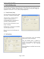
3.1 Editing Your Company Information
When you install the demo version of Door Fan 3.0, the company name is set to “Unlicensed
Company” by default. When you import your Software Certificate, your company name will
be configured into the software automatically.
All other company information (Address, Phone Numbers, etc) can be
modified through the Options menu in the top right of the screen.
Selecting Options: Company Info will open up up a window
and allow you to edit all of the information with the
exception of the Company Name.
The Company Name can only be modified by importing a
certificate.
Page 8 of 25
Door Fan 3.0 Software Users Manual
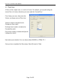
3.2 Importing your Certificate
The software license comes in the form of an encoded .txt file, either on a floppy disk or via
E-mail when the software is purchased.
From the Equipment tab click
[Choose a Certificate]
Next, select [Import New Certificate]. If you
received a disk from Retrotec containing your
license insert it now and select the .txt file on
the disk.
If you received the license via email; save the
attachment to a location of your choice on
your hard drive
The following screen will prompt you to browse
for the .txt file. Once located, highlight the .txt
file and click [Open]
Page 9 of 25
Door Fan 3.0 Software Users Manual
3.3 Using your Software Certificate
Once your certificate has been successfully
imported, it will appear on the certificates
page, on the list of all available certificates.
You are now ready to use the equipment
provided on your certificate.
Use the Mouse, Keyboard and Scroll Bar to
navigate through the list to your certificate.
Click on your certificate and then click [Use
Selected Certificate].
This will return you to the Current System
tab.
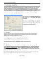
3.4 Viewing Your Current System
The Current System tab shows you the details of the equipment that will be used for all new
tests. It shows you the fans and gauges in your system and shows you which gauges are to be
used for which measurements.
For example in the picture to the right,
Certificate 454 has been selected.
It shows that the system is composed of
one Retrotec 2000 series fan with serial #
093759, one 60 Pa analog gauge with
serial # 093428 and one 250 Pa analog
gauge with serial # 093429.
It also shows that 093428, the 60 Pa
analog gauge, is to be used for room
pressure measurements and that 093429,
the 250 Pa analog gauge is to be used for
measuring flow pressure from Fan #1 in
your system.
Note: You must ALWAYS select the [Use Current Equipment] button if you change
Certificates.
Page 10 of 25
Door Fan 3.0 Software Users Manual
4 PreTest Building setup
The next step in performing a test will take you to the PreTest Tab. From this tab you will
set up your Group / Customer, Building and Zone. If you choose, you may also change your
equipment from this tab. To do so, select [Change Equipment].
4.1 Group/Customer Setup
Start by selecting the [New] button, name
your Group / Customer and select [OK].
*Only the Group / Customer Name is
required to continue, but it is
recommended that all information be
entered for reporting purposes.
Enter the Contact information for your
Group / Customer.
Existing Group / Customers are available
from the drop down menu.
Now you can move onto setting up your
Building
4.2 Building Setup
Just as you did above, enter your building
name and the contact information.
*Only the building name is required to
continue, but we suggest completing all the
contact information for your reporting
purposes.
Existing Buildings are available from the drop
down menu.
Page 11 of 25
Door Fan 3.0 Software Users Manual
4.3 Zone Setup
A Zone can be a single room, or a series of rooms. For example, you may be testing the
second floor of a house; therefore your zone would be “Second Floor”
First, Name your zone, then enter the
Volume, envelope area and Floor Area.
Volume is used to calculate the Air
Changes per Hour result.
Envelope Area is used to calculate the
Permeability result.
Floor Area is used to calculate the Specific
Leakage Area result.
Next select your standard. You can choose either EN13829 or ATTMA: TS-1
Once you have completed the Zone setup, Select [Proceed to Test]
Page 12 of 25
Door Fan 3.0 Software Users Manual
5 Conducting a Manual Test
There are 2 ways to perform a test with Door Fan 3.0, Manual Test and Auto Test. You may
conduct any number of tests on a particular building and Door Fan 3.0 will keep track of
each test. Saved tests are accessible by the drop down menu or by using the arrow keys. The
test screen is where all of the information about the test conditions will be recorded. On the
top left side of this screen you will see the details of your system. Before you begin,
confirm that the system, customer and enclosure are correct.
The first set of information required by
Door Fan 3.0 is the Setup and Room
conditions.
The user is guided though this required
information by selecting from the pull-down
menus and entering the static pressure and
temperature information directly.
5.1 Direction
Using the pull-down menu, choose which direction(s) you plan to test. Normally both
directions will be tested to eliminate errors in leakage area that can come from duct
leakage, static pressures, stack effect or wind.
“Pressurizing” is when the fan is blowing into the enclosure.
“Depressurizing” is when the fan is blowing out of the enclosure.
Both EN13829 and ATTMA: TS-1 encourage testing in both directions.
5.2 Operator
From the pull-down menu, select whether the operator is “in the room” or “out of the
room” depending on where the operator is standing during the test. The red room pressure
tube always goes through the door. When the operator is outside the room, the red room
pressure pickup tube goes inside the room. When the operator is in the room, the red room
pressure pickup tube goes outside the room.
Door Fan 3.0 automatically calculates the correct flow pressure by subtracting the room
pressure from the flow pressure when fan flow is towards the operator.
Page 13 of 25
Door Fan 3.0 Software Users Manual
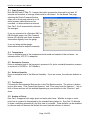
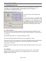
5.3 Static Pressure
Both EN13829 and ATTMA: TS-1 require that static pressure be observed for at least 30
seconds and a number of average values must be calculated. On the Manual Test page,
selecting the [Static Pressures] button
takes you to a sub-page where up to 10
static pressure observations can be
recorded. As observations are entered,
Door Fan 3.0 will automatically calculate
the averages.
If you are connected to a Retrotec DM-2 or
DM-2A digital gauge, the [Get Pressure]
button will retrieve each static pressure
observation digitally from the gauge.
If you are using another gauge,
observations must be keyed in manually.
5.4 Temperature
Enter an estimate here of the temperature both inside and outside of the enclosure. An
estimate within 10ºF/5ºC is adequate.
5.5 Barometric Pressure
Enter an estimate here of the barometric pressure in Pa (note: standard barometric pressure
at sea level is 101325Pa = 1013.25mBar).
5.6 Relative Humidity
Enter an estimate here of the Relative Humidity. If you are unsure, the software defaults to
50%.
5.7 Test Section
Following the Environmental Data section is the Test Results section. The section is broken
up into two areas, “Flow Toward the Operator” and “Flow Away from the Operator”. One or
both of these sections will be enabled depending on your selection in the “Direction” pulldown.
5.8 Number of Points
Door Fan 3.0 supports both single-point and multi-point tests. Whether a single or multipoint test is required is determined by the standard being tested to. Door Fan 3.0 defaults
to these conditions automatically the first time it is started. These defaults can be modified
by the user and will become the default the next time the software is started.
Page 14 of 25
Door Fan 3.0 Software Users Manual
5.9 Range Selection
Select a range that is appropriate for the room or zone that you will be testing. The larger
the leaks, the larger the range you will need to use. Currently only one range can be used
for each direction of testing.
Ideally you should choose a range that allows the fan to run as close to top speed as possible
and still allows you to achieve the correct pressure. That is, choose the smallest range ring
that still allows you to reach your maximum pressure
If the speed of the fan is too low for accurate results, Door Fan 3.0 will display a LOW error
and you will have to switch to a smaller range (for the entire direction), or you will have to
stop the test.
5.10 Room Pressure
This value is the static pressure difference between inside the enclosure and outside the
enclosure while the door fan(s) is running. To take the measurement, one pressure probe is
open at the gauge and the other is taken through the red tube, which is positioned on the
other side of the doorway. Regardless whether the user is inside or outside the enclosure,
the red tube is always on the side of the doorway opposite the operator.
Note: In a multi-point test, always begin with the highest pressure first, adjust your fan
range ring accordingly, then work your way down in pressures until you reach the end of your
test, or until the software displays that the flow is too low.
5.11 Flow Pressure
This value is the measure of the pressure difference across the inlet of the fan and is
translated into flow by the computer (or it can be looked up in a table supplied by the door
fan manufacturer). The certificate of calibration defines the exact relationship between
room pressure, flow pressure and volumetric air flow. In general, the flow pressure must
always be much greater than the room pressure. Door Fan 3.0 will warn the operator when
this flow pressure gets too low in which case; a more restrictive range is required.
Door Fan 3.0 supports the calculation of flow either from flow pressure alone, or, more
accurately, from flow pressure and room pressure.
5.12 Corrected Flow
This value comes from the calibration curves on the certificate. First, gauge readings are
corrected by Door Fan 3.0 (based on the gauge calibrations), then, flow is calculated using
the flow formulae on the certificate. The resultant flow is then corrected for temperature
or density according to the standard you are testing to.
Page 15 of 25
Door Fan 3.0 Software Users Manual
5.13 Error %
This value only applies to multipoint tests. The resultant value must be 6% or less for the
test to be acceptable.
5.14 Calculate Results
Once you have entered the required room and flow pressures, you can calculate your results.
When this button is selected, your results will be displayed on the “results” and “reports”
tabs. Please see Chapter 7 Results or Chapter 8 Reports for additional information.
Page 16 of 25
Door Fan 3.0 Software Users Manual
6 Conducting an Auto Test
To Use the Auto Test function of door Fan 3.0 you must have a DM-2A and it must be
connected to your computers USB port. Follow steps 4.1 to 4.3 to setup your
Group/Customer, Building and Zone Setup.
From the test tab, select the [Auto Test]
button.
If the auto test button is unavailable, shut
down Door Fan 3.0 and ensure that your DM2
is connected to your computer via the
supplied USB cable and that the DM-2 drivers
have been installed. Please see 2.1 to 2.3 for
instructions on installing your DM-2 Driver.
6.1 Pressure Settings
Select the maximum and minimum pressures and how many points you would like to test.
The maximum and minimum pressure and the number of points depends on the standard you
are testing to.
Both EN13829 and ATTMA: TS-1 recommend testing up to 100Pa.
Choose the distribution method of the points, either Logarithmic or Linear.
Since Pressure and Flow are a logarithmic relationship, distributing the points logarithmically
will produce consistent spacing and a more accurate representation of the leakage
characteristics of the room.
Distributing the points linearly will more heavily weight the higher pressures over the lower
pressures.
6.2 Direction
Using the pull-down menu, choose which direction(s) you plan to test. Normally both
directions will be tested to eliminate errors in leakage area that can come from duct
leakage, stack effect or wind.
Page 17 of 25
Door Fan 3.0 Software Users Manual
6.3 Operator
From the pull-down menu, select whether the operator is “in the room” or “out of the
room” depending on where the operator is standing during the test. When the operator is
outside the room, the red room pressure pickup tube goes inside the room.
6.4 Temperature
Enter an estimate here of the temperature both inside and outside of the enclosure. An
estimate within 10ºF/5ºC is adequate
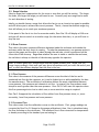
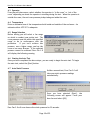
6.5 Range Selection
Before testing you will select a fan range
on which to conduct your entire test. The
room pressure must be within this specified
range to be in conformance with the
procedure.
If you can’t achieve this
pressure, use a higher range, seal up the
room or use more blowers. If the required
pressure cannot be achieved Door Fan 3.0
will display the following warning.
6.6 Starting the Auto Test
Once you have completed the above steps, you are ready to begin the auto test. To begin
the auto test, select the {Start} button.
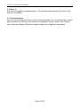
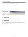
6.7 Auto Static Pressure
Unlike a manual test, Door Fan 3.0 will
take your static pressure readings
automatically.
Once you have selected {Start}, the
following screen will appear. Cover your
door fan and select {OK}
Door Fan 3.0 will now observe the static pressure for 30 seconds.
Page 18 of 25
Door Fan 3.0 Software Users Manual
You can see the static pressure being updated every 3 seconds.
Once the static pressure
readings are complete the
following screen will prompt
you to uncover your door
fan.
Once
you
have
uncovered the fan select
{OK}
6.8 Monitoring Auto Test
Although you may start auto test and simply walk away from your fan, it’s recommended
that you monitor the auto test process.
6.9 Completing Auto test
Once Auto Test is completed, Door fan 3.0 will take you back to the manual test Screen.
Note that the information from auto test is now carried over to the manual test tab and is
saved as any other test. You may now review the results from the results tab X.X and run
reports from the Reports tab X.X.
Page 19 of 25
Door Fan 3.0 Software Users Manual
7 Results
Page 20 of 25
Door Fan 3.0 Software Users Manual
8 Reports
Page 21 of 25
Door Fan 3.0 Software Users Manual
9 Range Selection
The general rule regarding range selection is that at every reading the Flow Pressure should
be at least 5 Pa greater than the corresponding Room/House Pressure. For example, if the
Room/House Pressure is 25 Pa, the Flow Pressure should be at 30 or higher.
One slight complication arises: when conducting a Multi-Reading test, your highest reading
(i.e. 50 Pa Room/House Pressure) must start with a Flow Pressure that is close to double the
Room/House Pressure (i.e. if your first Room/House Pressure reading is at 50 Pa, the
corresponding Flow Pressure must be approximately 90 - 100 Pa.). If this does not occur,
you will likely find that you "run out" of Flow Pressure near the end of the test, since the
Flow Pressure drops at a faster rate than the Room/House Pressure.
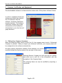
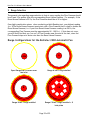
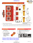
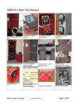
Range Configurations for the Retrotec 2200 Automatic Fan
A
OPEN
Open Range has no covers over
fan inlet
Range A has 1 ring installed
B
C8
Range B has 2 rings installed
Range C8 has 2 rings installed + 8
hole plate
Page 22 of 25
Door Fan 3.0 Software Users Manual
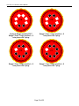
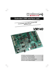
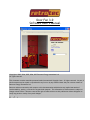
C6
C4
Optional Range available 2007
Range C6 has 2 rings installed + 8
hole plate with 2 plugs
Range C4 has 2 rings installed + 8
hole plate with 4 plugs
C2
C1
Range C2 has 2 rings installed + 8
hole plate with 6 plugs
Range C1 has 2 rings installed + 8
hole plate with 7 plugs
Page 23 of 25
Door Fan 3.0 Software Users Manual
10 Troubleshooting
Page 24 of 25