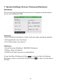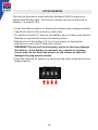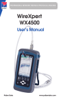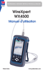
1
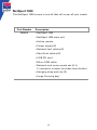
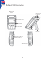
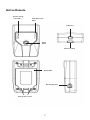
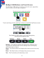
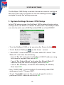
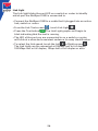
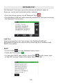
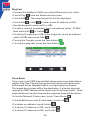
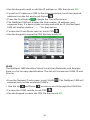
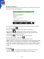
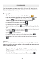
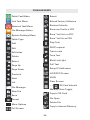
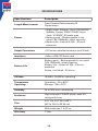
✗
Net pert
1400
Cable Qualifier
User Manual
Psiber Data GmbH a Softing Company
www.psiberdata.com
✗
Net pert
1400
Cable Qualifier
Table of Contents
Introduction........................................................................................................ 3
Kit Contents......................................................................................................... 4
Safety Information............................................................................................. 5
NetXpert 1400 Description............................................................................... 6
Active Remote Description.............................................................................. 7
NetXpert 1400 Touch Screen and Buttons.................................................... 8
General Operations........................................................................................... 9
System Settings............................................................................................... 10
First System Settings Screen (IP Setup)...................................................... 10
Second System Settings Screen (Display Settings).................................. 11
Third System Settings Screen (Time and Date).......................................... 12
Fourth System Settings Screen (Timeout Settings)................................... 12
Fifth System Settings Screen (User Information)....................................... 13
Sixth System Settings Screen (Firmware)................................................... 14
Seventh System Settings Screen (Firmware/Hardware versions).......... 17
Active Remote.................................................................................................. 18
Cable Test......................................................................................................... 19
Cable Test Overview....................................................................................... 20
Cable Test Setup.............................................................................................. 21
Cable Type........................................................................................................ 22
New Cable Type.......................................................................................... 22
Edit Existing Cable Type............................................................................. 22
Select Cable Type....................................................................................... 23
Cable Name................................................................................................. 23
Ethernet Cable Test.................................................................................... 23
Cable Faults...................................................................................................... 24
Saving Cable Tests as PDF............................................................................. 25
Saving a PDF Report........................................................................................ 25
Saving Test List as CSV.................................................................................. 25
Create a new Test List................................................................................... 26
File Manager................................................................................................. 26
Link Test............................................................................................................ 27
Port Discovery.................................................................................................. 27
POE Test............................................................................................................ 27
Tone................................................................................................................... 27
Link Light........................................................................................................... 28
2
Network Test.................................................................................................... 29
Link Test........................................................................................................... 29
DHCP................................................................................................................. 29
Ping Test........................................................................................................... 30
Trace Route..................................................................................................... 30
VLAN................................................................................................................. 31
Discovery Protocols....................................................................................... 32
File Manager..................................................................................................... 33
USB Mode......................................................................................................... 33
Icon Glossary.................................................................................................... 35
Customer service............................................................................................. 36
Maintenance.................................................................................................... 37
Specifications................................................................................................... 38
Warranty Information...................................................................................... 39
INTRODUCTION
The NetXpert 1400 Ethernet Speed Certifier offers a complete solution to
test copper cables. The NetXpert 1400 performs speed certification to test
the data-carrying capabilities of electrical Ethernet network cable up to 1
Gb/s by testing for noise in the network, detecting faults in the cable wiring,
and ensuring that cables are able to support the speed capabilities of active
equipment.
To certify Ethernet speed performance of copper cable runs, the NetXpert
1400 handheld tester conducts Bit Error Rate (BER) tests by sending data
packets down specified cable runs at defined data rates to check for errors at
the maximum throughput of the link. The NetXpert 1400 also reports on signal
quality that can impact high-speed data transmission by measuring signal
to noise ratio (SNR). Skew measurements report on the signal time delay
between pairs that can impact Ethernet data transmission. The NetXpert
1400 also provides continuity testing that detects opens, shorts, miswires,
split pairs, reversals, and high-resistance faults while accurately measuring
distance to faults and total cable length.
The NetXpert 1400 includes a comprehensive set of features for testing
active network capabilities: measure Power over Ethernet (PoE) to ensure
the correct power is available on the correct pins, use Port Discovery to
ensure the correct speed and duplex capability are available; connect
at Gigabit Ethernet and run Ping tests to verify connectivity to IP hosts;
discover network devices using Cisco Discovery Protocol (CDP) or Link Layer
Discovery Protocol (LLDP); VLAN discovery; Trace Route function displays the
path internet packets travel to reach a specified destination. The NetXpert
1400 also saves test reports and exports to PCs.
3
NetXpert 1400
The NetXpert 1400 comes in one kit that will cover all your needs.
Part Number
226605
Description
▪▪NetXpert 1400
▪▪NetXpert 1400 main unit
▪▪Active remote
▪▪Power supply (2)
▪▪Network test cables (2)
▪▪Sacrificial cables (2)
▪▪4 GB SD card
▪▪Micro USB cable
▪▪Network and coax remote set: #1-5,
F-connector coupler (includes foam holder)
▪▪Hanging strap and clip (2)
▪▪Large Carrying bag
4
Safety Information
To ensure safe operations of the NetXpert 1400, follow instructions
carefully and observe warning and caution messages in this
manual. Failure to observe warnings can result in severe injury or
death and can damage the equipment.
Notification
!
Voltage!
Definition
Warning/caution: potential for personal injury or
damage to equipment
Warning: hazards could cause harm or death
Conformité Européenne. Conforms to European
Economic Area directives.
Disposal information
!
W
arning! To avoid possible fire, electric shock,
or personal injury:
• Do not open the case; no user-serviceable parts are inside.
• Do not modify the tester.
• Do not use the tester if it is damaged. Inspect the tester before
use.
• The tester is not intended to be connected to active telephone
inputs, systems, or equipment, including ISDN devices. Prolonged
exposure to the voltages applied by these interfaces may damage
the tester.
• The Lithium Ion battery pack should be serviced by qualified
personnel. Only the original battery pack type should be used
with this product.
5
NetXpert 1400 Description
Modular cable
interface
RJ45 Jack and
F-connector
LCD Touch screen
Menu buttons
Power button
Battery Door
Kickstand
Micro USB and
SD card slot
D/C Charger plug
6
Active Remote
Battery charge
status LED’s
Linked/Pass/Fail
LED’s
RJ45 Jack
Status
button
Hook strap loop
Battery Door
D/C Charger plug
Battery door screws
7
NetXpert 1400 Buttons and Touch Screen
The NetXpert 1400 features buttons and a full color capacitive
touch screen to allow easy navigation.
Touch an icon to select an option
Touch and drag a list to scroll up or down or touch the Up/Down arrows.
The NetXpert 1400 buttons assist with Navigation,
starting and stopping a test.
Settings
Home
Back
Test
Settings - The Settings button will display the settings menu.
Pressing the settings while in the settings menu will display
additional menu screens.
Home - The Home button will display the home screen from any
menu.
Back - The Back button will display the previous screen.
Test - The Test button will start/stop a test.
8
General operations
On/Off
• Turn NetXpert 1400 on by pressing the Power button
.
• T ap the Power button to put the NetXpert 1400 in sleep mode.
•P
ress and hold the Power button to power the unit off.
Automatic Power Down
The NetXpert 1400 automatically enters sleep mode to conserve
battery power if no input or activity is performed on the device. See
System Settings on page 11 to adjust the length of time before the
automatic power down occurs.
NetXpert 1400 Active Remote
• Check the Active Remote battery status and last test result by
pressing the Status button.
9
System Settings
The NetXpert 1400 Setup consists of seven screens to configure
to
the unit to the user’s preference. Use the Settings button
navigate through the settings screens.
1. System Settings Screen: IPV4 Setup
In the IPV4 setup screen, the NetXpert 1400’s network tests can be
configured to use DHCP or a Static IP addresses. The NetXpert 1400
can also be set to use a DHCP provided DNS or a fixed DNS IP.
• Turn the NetXpert 1400 on by pressing the Power button
• T ouch System Settings

.
on the home screen.
• “ Use DHCP” is set as default. To enter static IP’s touch “Use
Static IP” and enter the following:
- T ouch “Set IP” and enter the NetXpert 1400 IP address using
the numeric keypad, then touch OK.
- T ouch “Set Subnet Mask” and enter the Subnet Mask IP
address using the numeric keypad, then touch OK.
- T ouch “Set Gateway” and enter the Gateway IP address,
then touch OK.
•U
se “DHCP DNS” is set as default. To manually enter DNS
addresses, touch “Choose DNS”.
• T ouch “Set DNS” and use the numeric keypad to enter a
preferred DNS IP address and touch OK.
10
2. System Settings Screen: Display Settings
Length settings:
• Under Display Units, touch either Feet or Meters.
• Under “Standard”, touch either T568A or T568B. The touched
wiring standard will be displayed in the cable test wiring diagram.

LCD screen brightness:
• To the right of Brightness, touch Set.
• Enter a number between 5 and 100 then touch OK. To cancel,
press the Back button  .
• To continue, touch More Settings or press the Settings button.
11
3. System Settings Screen: Time and Date
Set time/clock/date:
•U
nder Time Format, touch either 12-hour or 24-hour format.
• T o the right of Hours (1–12), touch Set Hour. Enter the hour you
wish to display then touch OK.
• T o cancel, press the Back button  .
• T o the right of Minutes (0-59), touch Set Minute. Enter the minutes
you wish to display then touch OK. To cancel, press the Back
button  .
•U
nder AM/PM, touch AM or PM on the screen.
•U
nder Date, set the month, day, and year: Touch Set Month. Enter
the number of the month, and then touch OK. To cancel, press the
Back button  .
• T ouch Set Day. Enter the number of the day, and then touch
OK. To cancel, press the Back button  .
• T ouch Set Year. Enter the year (all four digits), then touch OK. To
cancel, press the Back button  .
• T o continue, touch More Settings or press the Settings button
4. System Settings Screen: Timeout Settings

• T o set Standby power down:
- Touch Set to the right of Stand-by (default is 10 min).
- Enter a whole number from 1-10 for the number of minutes then
touch OK. To cancel, press the Back button  .
12
.
• To set System Shutdown Time:
- Touch Set to the right of System Shutdown (4 hour is the default
setting).
- Touch the number between 1 and 8 for the hours before system
shutdown then touch OK. To cancel, press the Back button  .
- To continue, touch More Settings or press the Settings button  .
5. System Settings Screen: User Information
The User Information screen allows the user to enter Company name,
user’s name, and email to be included on the NetXpert 1400 test
reports.

• Touch Set Company and use the keypad to enter the company name
(Max 20 Characters) then touch OK.
• Touch Set Name (Max 20 Characters) and use the keypad to enter a
name then touch OK.
• Touch Set E-mail and use the keypad to enter an email address then
touch OK.
• Touch Set Phone and use the keypad to enter a phone number
(20 characters maximum) then touch OK.
• To continue, touch More Settings or press the Settings button
13
.
6. System Settings Screen (Firmware)
You can have more than one version of firmware on the SD card –
all firmware files on the SD Card will be displayed on this screen.
Use the Up
and Down
buttons to scroll through multiple
firmware files.
• T he factory installed firmware revision (default firmware) is
displayed above the firmware file table.
• T he current firmware revision that is being used is displayed
above the firmware file table Current x.xx.
How to update the NetXpert 1400 Firmware:
Warning! Do not update the firmware if the battery charge is less
than 50%, unless the NetXpert 1400 is plugged in to A/C power.
•G
o to www.psiberdata.com
•D
ownload the firmware file to your computer. Take note of where
the Firmware file is saved.
Upload firmware using the SD Card:
•R
emove the SD Card (located on the left side of NetXpert 1400)
and insert it into your computer using an SD Card reader. Your
computer will recognize the SD Card as a removable drive. Open
the removable drive folder and copy the firmware file from your
computer to the removable drive window. Re-insert the SD Card
into the NetXpert 1400. Proceed Installation; “NetXpert 1400
Update” below to install complete the update.
Note: When installing SD Card with firmware update refresh the
firmware table by exiting and then reentering the firmware screen.
14
Upload NetXpert 1400 firmware using the Micro USB cable:
• Plug the included micro USB cable into the NetXpert 1400 then
plug the other end of the cable into your computer.
• Touch File Manager
.
• Touch More Options
.
• Touch USB
. The NetXpert 1400 will reboot into File Transfer
Mode as shown in the image below.
• The NetXpert 1400 will be recognized by your computer as a
removable drive. If your computer does not automatically prompt
you to view the removable drive, click on the windows start menu,
click on “Computer”, and then double click on the removable
drive.
Note: The removable drive may be listed in “Computer” as an SD
Card, as the NetXpert 1400 simulates an SD Card reader.
• Navigate to the firmware file that was saved to the computer from
www.psiberdata.com. Right click on the firmware file then click
on “Copy”.
• Navigate back to the NetXpert 1400 removable drive and right
click in the removable drive window and click on “Paste”.
• Close the removable drive window then click on “safely remove
hardware” on your computers toolbar on the bottom left. Eject
“MQX Mass Storage Device”.
• Remove the micro USB cable from the NetXpert 1400.
• The NetXpert 1400 will automatically reboot. Follow the intructions
below to complete the udate.
15
Install NetXpert 1400 Update:
• F rom the home screen, Touch System Settings
• T ouch More Settings or press the Settings button
firmware screen is displayed (6th settings screen).
.
until the
•U
pdate by touching the firmware file in the firmware table then
touch Update Firmware
on the screen. A new screen will
appear, confirming that you are updating firmware. Touch OK
to continue or Cancel. Another window will appear: Updating
firmware.
Warning: System will reboot after update. Please make sure
battery is not low.
Press OK to continue or Cancel.
• T o reset to the factory firmware, touch the Reload Factory
Firmware
. A new screen will appear, confirming that you
are deleting the firmware update and restoring to factory default.
You will be prompted to touch OK to continue or Cancel to cancel.
NetXpert 1400 will then restart.
• T o reset to the factory settings, touch the Reset Settings
.A
new screen will appear, confirming that you are restoring factory
Cable Type list. You will be prompted to touch OK to continue or
Cancel to cancel.
16
7. System Settings Screen: Firmware/Hardware
Versions
This screen will display which versions of firmware and hardware
are in your NetXpert 1400.

Firmware
• Boot (initializes hardware, loads, and executes operating system)
• GUI (graphical user interface)
• PIC (cable tester processor)
Hardware
• Serial Number (NetXpert 1400 MAC Address)
• Battery (type of battery)
• NAND size (flash memory in megabytes)
to return to the first System
Press the More Settings soft key
Settings screen or press the Home button
to return to the Home
Screen.
17
Active Remote
The Active Remote is used with the NetXpert 1400 to perform a
speed certification test. The Active remote can be configured to
display 1-4 remote ID’s
•P
ress the Status button to display the battery percentage and the
Pass/Fail result of the previous cable test.
• T o set the remote ID, remove the battery door screws (see Active
Remote on pg.8) and remove the battery door).
•G
ently pull out the battery (it is not necessary to unplug the
battery to access the ID indicator switch.
WARNING! Do not pull on the battery wires as this may damage
the battery. If the battery is removed, use caution as it plugs
in one way. Do not force the plug in to the remote as this will
damage the plug and/or remote.
•P
ush the desired ID switch up and push the other keys down (see
image below).
Remote set to ID 1
18
Cable Test
The NetXpert 1400 performs a wire map test, measures cable length
using capacitance and TDR, and speed certifies cables up to 1 Gigabit.
Test Options
There are five test options depending on the type of remote being
used or if no remote being used. Below are descriptions of the test
results given for each test option. To see a full screen view of the
. Press the Back button
to exit
results, touch Full Screen
the full screen view.
Active Remote:
When an active remote is being used to perform a cable test,
the NetXpert 1400 will display the cable wire map, active
remote ID, SNR, SKEW, and BER test results. The NetXpert
to indicate that the
1400 will display a green check mark
cable has passed the network speed certification test.
Set of 8 Network Testing Remote (optional):
When a network remote is being used, the NetXpert 1400 will
display the wire map, cable length, ID, and an orange check
mark
indicating that the cable passes the wire map test.
Set of 20 Coax Remote (optional):
When using coax remotes, the NetXpert 1400 will display the
remote ID. If a short or open is detected, the NetXpert 1400 will
measure the distance to the fault.
Open Ended Test
When no remote it being used, the NetXpert 1400 will display
the cable length and “Status” for each pair.
Set of 5 ID Only Remote RJ45/Coax:
When an ID only remote is being used, the NetXpert 1400 will
only show the remote ID on the Detailed Test Results screen.
The ID remotes are used to assist with mapping and labeling
network cable runs.
19
Cable Test Overview
Detailed Test Results
Cable Test List
The Cable Test
menu saves all tests, except when using ID
only remotes, to a file in internal memory with the extension “.tst”.
The Cable Test has two screens; a Detailed Results screen and
a spreadsheet-like Test List screen. Testing can be initiated from
either screen by pressing the Test button
. When initiating
a test from the Test List Screen, only a summary of the results is
shown. If no test file is defined by the user, “UNTITLED1.TST” will
be used to save test results to. The test file name that is being used
appears in the title bar along with the current function, Cable Test.
To navigate from the Detailed Results screen to the Test List, touch
at the bottom of screen. The Test List will be displayed
List
with a highlighted cable test in the list which the Detailed Results
screen was displaying results for. To navigate from the Test List
to the Detailed Results screen, highlight a cable test in the list that
you would like to display the test details for and touch Select
at the bottom of the screen. To exit the Test List without making a
selection, press the Back button
.
Before testing a cable, the list file should be selected or created
to save results. The cable type should be selected or created from
the cable type list and the cable name prefix and beginning index
number can be defined or kept as default. Each test performed will
use the currently selected test definition.
Note: All these test setup functions are on the Detailed Results
screen.
20
Cable Test Setup
. If the list screen is
From the home screen, touch Cable Test
displayed, press Select
at the bottom of the screen or the Back
to go to the Detailed Results screen:
button
Creating a New Test List:
Touch New File
at the bottom of the Detailed Results screen,
enter a file name (20 characters max.), and touch OK. Returns to
Detailed Results screen. Test List name will appear in the title bar.
See File Manager section on page 33 for additional File manager
instructions.
Opening a Test List:
If a Test List (.tst) file already exists, it can be selected from a
directory list, by touching File Manager
. The file manager
screen will open showing the internal memory directory of TST
files. Touch to highlight the desired file in the list and select File
Open
to open the test list and return to the Detailed Results
screen.
Selecting a Cable Type:
on the right-hand side of the Detailed Results
Touch Cable Type
screen. A list of defined cable types will be displayed with a scroll
bar on the right-hand side. If the cable type to be used is in the list,
highlight it by touching the line and touch Select
to make it the
current cable type and return to the Detailed Results screen. See
Cable Type section on page 23 for instructions to edit, add or delete
cable types.
Setting Cable ID Names:
The cable ID naming convention is a prefix plus an incrementing
three digit index number. The prefix should be limited to 9
characters. With the three digit index there will be a total of 12
characters in the name. From the Detailed Result screen, Touch
Edit
on the right-hand side of the Detailed Result screen. The
Cable Test Setup screen will appear with the current values for
prefix and index displayed. Touch Edit
to the right of the value to
be changed, type in new name or index and touch OK. Touch Save
to keep the edited values or touch Cancel
to exit without
saving. Cable ID’s can also be edited from the Test List to be any 12
character name, with or without numbers. See the Test List section
on page 26 for instructions on editing, adding and deleting cables.
21
Warning! All cable test files refer to the cable type list to extract
information about the cable definition used in the testing. If a cable
type is deleted or the name changed, any Test List that uses that
cable type will be corrupted. It is suggested that any PDF or CSV
files created from a Test List affected by a cable list change be
generated before making a change to a cable type that is used by
the test list.
Cable Type
The cable type list contains a list of all the defined cable types to be
tested. Cable type list is used to select the test criteria for cables to
be tested and manage the list by editing, adding or deleting entries.
New Cable Type
• From the Cable Test Screen, touch Cable Type
• To add a new cable type, touch new
.
.
• Enter cable name on next screen and press OK.
• Touch test connector “RJ45”, “Coax” or “2 Pair” and press OK.
• T ouch a data rate (0 Mbps, 100 Mbps, 1 Gbps) for a Bit Error Rate
test and touch OK (coax skips this step).
• E nter length constant in pF/foot or pF/meter and press OK.
Typical cable length constant (pF/ft, pF/m):
- CAT5/5E: 15 pF/ft
- CAT6:
15 pF/ft
- CAT7:
15 pF/ft
- RG6:
16.5 pF/ft
- RG58:
27 pF/ft
- RG59:
16.5 pF/ft
Touch Shielded cable, Non-shielded Cable, or Ignore Shield then
touch OK.
Edit Existing Cable Types
• T ouch a cable type from the Cable Type list. With a line
highlighted, the buttons functions are:
• T ouch Edit
to edit the highlighted entry. The name may be
changed or kept default. All other settings are entered as in New
Cable Type.
22
• To delete highlighted entry, touch Delete
.
• Touch OK to confirm action or cancel.
Select a Cable Type to Test
• T ouch a cable type from the Cable Type list. Add the highlighted
cable type to the test list by touching Select . The Cable Test
screen will appear with the added cable type displayed in the
lower left of the screen.
Cable Name
• F rom the Detailed Results screen, touch edit
.
• T o enter a cable name prefix touch Edit
. The prefix is the
first part of the cable name that does not increment when a
cable is added to the test list. Enter the desired prefix using the
touchscreen keypad and touch OK.
• T ouch Cable Index
to edit the incrementing numerical portion
of the Cable ID. When the desired Index is entered, touch OK.
• T o accept the changes, touch Save
touch Cancel
.
. To exit without saving,
Ethernet Cable Test
• From the home screen, touch Cable Test
.
•C
onnect an Ethernet cable to the NetXpert 1400 then connect
the Active Remote to the opposite end of the cable. If an active
remote is not being used, connect a Network testing ID remote to
the opposite end of the cable.
* If testing an Ethernet cable that is terminated to a wall plate,
use the included RJ45 patch cables to connect to the wall plate or
modular RJ45 jack.
• T ouch Cable Type
.
• T ouch the desired cable type from the cable type list and then
touch Select Type
.
•P
ress the Test button
to perform a test. The NetXpert 1400
will add an incremented cable name to the Test List and perform
a test.
23
• T o perform another test, press Test button
. The NetXpert
1400 will add another cable to the test list and perform a test.
• T o re-test another cable test, touch the left or right arrows to
navigate to the desired cable test then touch Retest
.
Coax Cable Test:
• Connect the included F81 barrel adaptor to the NetXpert 1400 module
and then connect a Coax ID Remote to the opposite end of the cable
• F rom the Home Screen, touch Cable Test
• T ouch Cable Type
.
.
• T ouch the desired coax cable type from the cable type list then
Select .
•P
ress the Test button
to perform a test.
Cable Faults
Below are the types of cable faults that the NetXpert 1400 will
detect and display if the cable under test is damaged or faulty.
Open:
The wire(s) is not continuous throughout the cable. This may be
caused by improper termination or a break in the cable.
Short:
Two or more wires in the cable are connected. This may be caused
by an improperly terminated cable, damaged RJ45 plug/jack, or a
damaged cable.
Miswire:
Cable’s wire connection does not follow TIA568A/B Ethernet
cabling standards. This occurs when there is an error made when
terminating the cable.
Split:
The cable has been wired with correct continuity but not with
correct circuitry pairing. This most often happens when the cable is
terminated consistently at both ends but in the wrong order.
Skew:
The delay skew is higher than 35 nanoseconds. This may be caused by
velocity of propagation or length difference between the cable pairs.
24
SNR:
The Signal to Noise Ratio is lower than 22dB. This may be caused
by attenuation, excessive crosstalk, or noise that is imposed on
the cable from an external source such as electrical cabling,
fluorescent lighting, or electrical equipment.
Saving Cable Tests as a PDF
In the Detailed Results screen there are two options; the NetXpert
1400 can save the last cable test results as PDF, or the entire test
list can be saved as a report.
• From the Detailed Result screen, touch More Options
• Touch PDF
.
.
• Enter the desired file name for your test and touch OK.
•N
etXpert 1400 will save the PDF under your new file name to
external memory (SD Card).
Saving a PDF Report
• From the Detailed Results screen, touch More Options
• T ouch the PDF Report
.
on the Cable Test screen.
• Enter the desired file name for your test report and touch OK.
•N
etXpert 1400 will save the PDF under the new file name to
external memory (SD Card).
** DO NOT REMOVE SD CARD UNTIL DIALOG BOX DISAPPEARS**
Saving the Test List as a CSV file
The test list can be saved as a CSV file to be opened with excel or
CSV compatible software.
• From the Cable Test screen, touch More Options
• Touch CSV
.
• Use the keypad to enter a file name then touch OK.
• The CSV file will be saved to external memory (SD Card).
25
Test List
The Test List screen contains a list of cables that have been tested.
The Test List allows the user to view, save, retest, add, or edit cable
tests.
• From the Cable Test screen, touch Test List
• T ouch the Up and Down arrows
cable test list.
.
to scroll through the
• T o edit the cable name of an existing cable test, touch edit.
•U
se the keypad to enter a new cable name then touch OK.
• T o add a cable from the test list screen touch Add
.
• T ouch OK to accept the automatically incremented cable name or
use the keypad to enter a new cable name then touch OK.
• T o delete a cable from the test list touch Delete
.
• T o retest a cable from the test list, touch a cable from the list,
touch select then touch retest
. Pressing the test button
again will add a new cable to the test list and a test will be
performed.
Create a new Test List
When a Test list is created, The NetXpert 1400 automatically saves
your test list as a .tst file to internal memory. The .tst file can be
transferred to an SD card or computer. TST files can be reopened
by a NetXpert 1400 for editing, retesting, or adding new tests.
• T o create a new .tst file, touch Cable Test
screen.
from the home
• T ouch New File
and enter a file name then touch OK. The .tst
file will be saved to internal memory.
File Manager
• From the Cable Test screen touch File Manager
.
• F ile manager contains tst, pdf, and csv files that
have been saved to internal or external memory. See “File
Manager” on page 33 for File manager instructions.
26
Link Test
The Link Test menu displays port services provided by an active
switch, router, or NIC.
• From the home screen, touch Link Test
.
• Touch the desired Link Test option.
Port Discovery
The Port Discovery test will display port services and capabilities
such as link speed, MDI/MDI-X, auto negotiation, and SNR of each
pair within the cable.
• Port Discovery is the default Link Test option.
• Press the Test button
• Touch PDF
to perform a Port Discovery test.
to save the Port Discovery test results.
• Use the keypad to enter a file name then touch OK.
POE Test
The detailed POE test displays POE mode, type, and min/max load.
• From the Link Test screen, touch POE
• Press the Test button
• Touch PDF
.
to perform a POE test.
to save the POE test.
• Use the keypad to enter a file name then touch OK.
Tone
The tone generator will transmit a frequency onto a cable to be
made audible using a tone probe. The tone generator will assist in
locating an inactive cable in a bundle, patch panel, or wall plate.
• From the Link Test screen
• Press the test button
, touch Tone
.
to transmit the tone.
• T ouch Previous
or Next
transmit the tone.
to alternate which pin or pair to
• T ouch Low/High to change the tone output level and cadence
(default is set to low).
•U
se a tone probe to trace the tone alongside or at the end of the
cable.
27
Link Light
The Link light blinks the port LED on a switch or router to identify
which port the NetXpert 1400 is connected to.
•C
onnect the NetXpert 1400 to a cable that it plugged into an active
hub, switch or router.
• F rom the Link Test screen
, touch Link Light
.
•P
ress the Test button
. The Link Light graphic will begin to
blink indicating that the test is running.
• T he LED of the port you are connected to on a switch or router
will blink at a slow and consistent cadence for easy identification.
• T o select the Link speed, touch the Left
or Right arrows
..
The Link Light can be connected at 10Mbps half or full duplex,
100 Mbps half or full duplex, 1Gbps half or full duplex or auto.
28
Network Test
The Network Test menu provides advanced network tests to
discover, verify and troubleshoot the network.
• From the home screen, touch Network Test
.
• T he NetXpert 1400 will automatically establish a link upon entering
the Network Test screen.

Link Test
Upon entering the Link Test screen, the NetXpert 1400 will
automatically perform a port test by acquiring an IP address and
DHCP information.
DHCP
• T ouch DHCP
from the Network test screen.
•P
ress the Test button
.
• T o save the DHCP test results, touch PDF
on the lower right
of the LCD screen. Enter a file name then touch OK.

29
Ping Test
• Connect the NetXpert 1400 to an active Ethernet port or cable.
• Touch Ping
from the Network test screen.
• Touch Add
. The saved target list will be displayed.
• Touch Add
or Edit
to enter a new IP address or URL.
• Use the keypad to enter an IP or URL
• T o edit or remove an address, touch an address under “IP/URL”
then touch Edit
or Delete
.
• T o add an IP address or URL to the target list, touch an address
under IP/URL then touch Add
.
• T o ping the Targets, press the Test button
.
• To stop the ping test, press the Test button
.

Trace Route
Trace route is an ICMP ping test that shows much more detail than a
regular Ping Test. Choose a target and each device along the route
to the target will be displayed with a corresponding hop number.
The largest hop number will be the destination. If a device does not
respond to ICMP dashes will be shown next to the hop number. Three
pings will be sent to each hop and the response times will be shown.
.
• From the Network Test screen, touch Trace Route
• To Add/Edit trace route IP addresses, touch List
• To delete an address, touch Delete
.
• To add an IP address or URL, touch Add
.
• To edit an IP address or URL, touch Edit
.
30
.
• Use the keypad to add or edit the IP address or URL then touch OK.
• To add an IP address or URL to the trace route test, touch the desired
address from the list and touch Select
.
•P
ress the Test button
to begin the Trace Route test.
• T he NetXpert 1400 will display the hop number, IP address, and
response time. If a device does not respond with an IP, the NetXpert
1400 will display dashes “- - - -“for that device.
• T o save the Trace Route test list, touch CSV
.
•U
se the keypad to name the CSV file then touch OK.
VLAN
The NetXpert 1400 identifies Virtual Local Area Networks and displays
them in a list for easy identification. The list will include the VLAN ID and
Priority.
• F rom the Network Test screen, touch VLAN
automatically list the available VLAN’s.
• Use the Up
and Down
. The NetXpert 1400 will
arrows to scroll through the VLAN list.
• T o save the VLAN results, touch CSV
.
•U
se the Keypad to name the CSV file then touch OK.
31
Discovery Protocols
The Discovery Protocol menu provides Cisco switch Protocol and
Link Layer Protocol information.

• Connect the NetXpert 1400 to an active Ethernet port or cable.
• Touch CDP/LLDP
• Touch CDP
.
to display Cisco switch information.
• T ouch LLDP
to display Link Layer switch information.
*Note: the information displayed may vary depending on the
information provided by the switch.
• Touch Clear
to clear the CDP or LLDP screen.
• To save the results, touch PDF
.
•U
se the keypad to enter a file name then touch OK.
Note: CDP/LLDP information is obtained from a broadcast packet
from a switch or switches on the network. The time between
packets is a switch setting and can be in excess of 30 seconds or
tuned off. Usually, only managed switches support CDP and or
LLDP.
IP Settings
to configure the NetXpert IP setup (see “First
• T ouch IP
System Settings” on page 10 for additional instructions).
32
File Manager
The File manager contains saved PDF, CSV, and TST test files. In
this menu, they can be renamed, deleted, or transferred between
internal and external memory.
Managing Files
• From the home screen, touch the File Manager
.
• T he File Manager displays files from internal memory and
external memory (SD Card). Touch Show Internal
or
to view the desired memory location.
Show SD
• To display PDF files only, touch PDF
.
• To display CSV files only, touch CSV
• T ouch the Up v and Down
list.
arrows to scroll through the file
• T o copy files, touch one or more files from the list, then touch
Copy to SD
• Touch
or Copy to Internal
.
for more options.
• To open a .tst file, touch a .tst file then touch Open
.
• T o delete a file, touch a file from the list and touch delete
.
USB Mode
Files can be uploaded to a computer by removing the SD card and
inserting it into an SD Card reader, or by plugging the NetXpert 1400
into a computer via USB.
• T o upload files from the NetXpert 1400 to a computer via
USB, plug a micro USB cable into a computer then into the
NetXpert 1400.
• F rom the File Manager screen, touch More options
33
.
• T ouch USB. A dialog box will appear to confirm the selection.
Touch OK to proceed or Cancel to return to the file manager
screen.
• Open the removable storage device drive on your computer.
• Double click on the PDF or CSV folders to view the test files.
• Copy the desired files to your computer.
SD Card
• Remove the SD Card from the NetXpert 1400. Push the SD Card
inward then release to unlock the SD Card.
34
Icon Glossary
Cable Test Menu
Retest
Link Test Menu
Reload Factory Software
Network Test Menu
Restore Defaults
File Manager Menu
Save one Test to a PDF
Save *.tst file to a PDF
System Settings Menu
Save *.tst file as CSV
Cable Type
Ping Test
Add
DHCP request
Edit
Trace route
Edit Index
Tone Test
Delete
Blink Link Light
Select
PoE Test
Page Up
Setup IP Addresses
Page Down
LLDP/CDP Screen
Previous
VLAN
Next
Clear Screen
List
↔
File Manager
Memory View Toggle
New File
Copy to SD Card
Save
…
SD Card Internal
File Open
Cancel
Delete File
More Options
Copy to Internal Memory
Full Screen
35
CUSTOMER SERVICE
Contacting Psiber Data
For technical information and support please contact
the Psiber Office in your country.
Psiber Europe: Psiber Data GmbH, Phone: +49 (89) 8913 6060,
e-mail: [email protected], www.psiberdata.com,
Psiber Asia/Pacific: Psiber Data Pte. Ltd., Phone: +65-6569-6019,
e-mail: [email protected], www.psiberdata.com
36
MAINTENANCE
Batteries
• T he NetXpert 1400 is powered by a rechargeable Lithium ion
battery.
• T o charge the battery, plug the charger into the side port and
then plug the charger into the power source.
•N
etXpert 1400 battery is not user serviceable. In the event
you need to remove the battery, unscrew the back panel of
the NetXpert 1400 and unplug the battery from the NetXpert
1400. Be sure to remove all the leads connecting the battery
to the device.
NOTE: The advanced Lithium ion battery is designed to last
the life of the unit and should not have to be replaced.
Lithium ion batteries are hazardous waste and should be
disposed of in compliance with local, state, and federal
hazardous waste regulations.
Cleaning
•U
se a clean, damp cloth to clean the NetXpert 1400.
• B
efore cleaning, disconnect all cables from the NetXpert
1400. Failing to disconnect cables can damage the device
and cause personal injury.
• Do
not use harsh cleaners, abrasives, or solvents.
Storage
•W
hen not in use, store the NetXpert 1400 in the included
protective case.
•D
o not expose the NetXpert 1400 to high temperatures
(above 80°C) or humidity. See the specifications section
for temperature limits.
37
SPECIFICATIONS
Specifications
Description
Length Measurement
Time Domain Reflectometry &
Capacitance
Power
▪▪ Wall Power Adapter: Input 100-240VAC
50/60Hz, Output 12VDC 2.5ADC Input
Jack: 10-28VDC, 20 watts max
▪▪ Battery pack - Rechargeable Li-ion
rated 7.8V, 5500mAh, initial capacity
▪▪ Battery life - Linked @ 1Gb - 8 hours
minimum
Output Connectors
▪▪ 8-Position shielded modular jack (Data)
Interfaces
▪▪ Micro USB, SD flash card
Battery Life
Battery pack - Rechargeable Li-ion rated
7.8V, 5500mAh, initial capacity
Battery life - Linked @ 1Gb - 8 hours
minimum
Active, not linked - 20 hours
Altitude
10,000 ft. (3,048 m) operating
Temperature
Operating:
Operating: -10 to 60°C
Storage: -30 to 70°C
Humidity
10 to 90% non-condensing
Enclosure
High-strength PC/ABS plastic with V0
rating with boot
Size
2.41”H x 4.18”W x 9.03”L
(6.12 x 10.61 x 22.94 cm)
Weight
With batteries: 1 lb 12 oz
Warranty
1 Year
38
Warranty
Psiber Data warrants that the product shall be free from defects in parts or
workmanship for a period of 12 months from the date of purchase if used
in accordance with Psiber Data operating specifications.
THIS IS THE ONLY WARRANTY MADE BY Psiber Data AND IS EXPRESSLY MADE IN LIEU OF ALL OTHER WARRANTIES EXPRESSED
OR IMPLIED, INCLUDING BUT NOT LIMITED TO ANY IMPLIED WARRANTIES OF MERCHANTABILITY OR FITNESS FOR ANY PARTICULAR PURPOSE.
Should any parts or workmanship prove defective, Psiber Data will repair
or replace at Psiber Data’ option, at no cost to the Buyer except for
shipping costs from the Buyer’s location to Psiber Data. This is Buyer’s
SOLE AND EXCLUSIVE REMEDY under this Agreement. This warranty
does not apply to products which have been subject to neglect, accident
or improper use, or to units which have been altered or repaired by other
than an authorized repair facility.
For European-Customers:
Return of Equipment – To return a product to Psiber Data GmbH, first
obtain a Return Authorization number from our Customer Service by
calling +49-89-89136060. The RMA# must be clearly marked on the
shipping label.
To: Psiber Data GmbH
Lise-Meitner-Str. 3
82152 Krailling
Germany
RMA# XXXXXXXX
For ASIA/PACIFIC-Customer:
Return of Equipment - To return a product to Psiber Data Pte. Ltd., first
obtain a Return Authorization number from Our Customer Service by
calling +65-6569-6019 or e-mail: [email protected]. The RMA#
must be clearly marked on
The shipping label.
To: Psiber Data Pte. Ltd.
3 Science Park Drive
#03-09 The Franklin
Singapore Science Park 1,
Singapore 118223
RMA# XXXXXXXX
Copyright 2014 Psiber Data. All rights reserved.Psiber and the Psiber logo are trademarks of Psiber Data
GmbH . All rights reserved.
39
✗
Net pert
1400
Cable Qualifier
EUROPE/M.EAST/AFRICA
Psiber Data GmbH
a Softing Company
Lise-Meitner-Str. 3
82152 Krailling
Germany
Phone: +49 (89) 8913 6060
e-mail: [email protected]
www.psiberdata.com
Asia / Pacific
Psiber Data Pte. Ltd.
3 Science Park Drive
#03-09 The Franklin
Singapore Science Park 1,
Singapore 118223
Phone: +65-6569-6019
e-mail: [email protected]
www.psiberdata.com
For technical information and support please
contact the Psiber Office in your country.
www.psiberdata.com
40