1
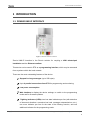
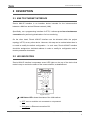
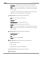
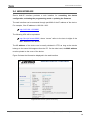
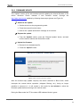
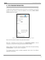
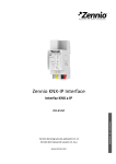
Zennio KNX-IP Interface KNX to IP Interface Application Program version: [1.1] User Manual version: [1.1]_a www.zennio.com USER MANUAL ZSY-IP-INT Zennio KNX-IP Interface CONTENTS Contents ................................................................................................................................ 2 1 2 Introduction .................................................................................................................. 3 1.1 Zennio KNX-IP Interface ........................................................................................ 3 1.2 Installation............................................................................................................. 4 1.3 Zennio KNX IP Interface as a Programmer ............................................................ 5 1.3.1 Parallel Downloads ............................................................................................ 5 1.3.2 Limitations ......................................................................................................... 6 Description .................................................................................................................... 7 2.1 KNX to Ethernet Interface ..................................................................................... 7 2.2 LED Indicators ........................................................................................................ 7 2.3 Manual Function Button ....................................................................................... 9 2.3.1 2.4 Hard Reset to Factory Defaults ......................................................................... 9 Web Interface...................................................................................................... 10 2.4.1 3 Firmware Update ............................................................................................ 11 ETS Parameterisation .................................................................................................. 13 3.1 Default Parameterisation .................................................................................... 14 3.2 General ................................................................................................................ 14 3.3 IP Configuration................................................................................................... 14 http://www.zennio.com Technical Support: http://zennioenglish.zendesk.com 2 Zennio KNX-IP Interface 1 INTRODUCTION 1.1 ZENNIO KNX-IP INTERFACE Figure 1 Zennio KNX-IP Interface Zennio KNX-IP Interface is the Zennio solution for coupling a KNX twisted-pair installation and the Ethernet medium. This device can be used in ETS as a programming interface, which may be accessed from anywhere within the local network. These are the most outstanding features of the device: Support for long messages (up to 250 bytes). Up to 4 parallel connections from ETS for programming and monitoring. Low power consumption. Web interface to display the device settings, to switch to the programming mode and for firmware updates. 7 lighting indicators (LEDs): two bus state indicators per line (with detection of abnormal situations: excessive bus load, message retransmissions, etc.), one more indicator per line for the state of the filtering function, and one additional indicator for the programming mode. http://www.zennio.com Technical Support: http://zennioenglish.zendesk.com 3 Zennio KNX-IP Interface 1.2 INSTALLATION 1. 2. 3. 4. 5. 6. 7. 8. 9. 10. 11. 12. LAN (RJ45) connector. LAN status LED. LAN traffic LED. Manual function button. KNX status LED. KNX traffic LED. Prog./Test LED. Prog./Test button. External power supply socket. KNX connector. 1 2 6 3 4 7 8 5 9 10 11 12 Figure 2 Element Diagram This device requires an external power supply (12V to 30V DC) through connector (6), as it is not powered through the KNX bus. Figure 2 shows a scheme with all the LED indicators and connections. To couple a KNX twisted-pair (TP) line and a LAN, the KNX bus (12) and Ethernet (7) cables as well as the external power (6) must be connected. After the connection, the device can be conveniently mounted on the DIN rail by the usual procedure The programming button (11) shown in Figure 2 may be pressed to set the device in programming mode. After a short press, the programming LED (5) will light in red. The behaviour of the additional LEDs and the manual function button will be described in section 2.3. For detailed information about the technical features of the device, as well as on security and installation procedures, please refer to the device Datasheet, bundled within the original packaging of the device and also available at http://www.zennio.com. http://www.zennio.com Technical Support: http://zennioenglish.zendesk.com 4 Zennio KNX-IP Interface 1.3 ZENNIO KNX IP INTERFACE AS A PROGRAMMER Zennio KNX-IP Interface can be used in ETS as a programming interface. In addition to an IP address, this device must be assigned a KNX individual address for this purpose. Note: to detect the device as a programmer in ETS, it needs to be powered up and connected to the same network as the PC, as well as to a TP line. If the latter line is disconnected, the device will no longer be visible as a programmer. 1.3.1 PARALLEL DOWNLOADS ETS offers the option to perform multiple parallel downloads from a single project. This option is only available for connections via a KNX-IP router or a KNX-IP interface. Certain conditions must be met: Each download must be performed on a different line. For each line, it is necessary to select one Zennio KNX-IP Router or one Zennio KNX-IP Interface to perform the download. This is configured by right-clicking on the line and, under "Set Connection", selecting the desired connection (once selected, it will not be available for other lines). Figure 3 ETS parallel downloads. http://www.zennio.com Technical Support: http://zennioenglish.zendesk.com 5 Zennio KNX-IP Interface An additional restriction applies to the parallel downloads: they are not available to download physical addresses. When performing this type of downloads, the link device used by ETS is not the one configured for the line but the general one. 1.3.2 LIMITATIONS It is important to note that Zennio KNX-IP Interface, when performing as a programmer, does not allow bus monitoring as long as other parallel connections remain open (the ETS bus monitor will not be available). Moreover, Zennio KNX-IP Interface does not allow being unloaded (unprogrammed) from ETS. Equivalently, it can be reset to the factory default state, as explained in section 2.3.1. http://www.zennio.com Technical Support: http://zennioenglish.zendesk.com 6 Zennio KNX-IP Interface 2 DESCRIPTION 2.1 KNX TO ETHERNET INTERFACE Zennio KNX-IP Interface is an interface device intended for the interconnection between a KNX bus and an Ethernet network (LAN). Specifically, as a programming interface for ETS, it allows up to four simultaneous connections for performing downloads or for bus monitoring. On the other hand, Zennio KNX-IP Interface can be allocated within the project topology in ETS, as any other device. However, this step can be omitted when there is no need to modify the default configuration – in such case, Zennio KNX-IP Interface should be assigned an individual address in order to modify its configuration and to receive parameter downloads. 2.2 LED INDICATORS Zennio KNX-IP Interface incorporates seven LED lights on the top of the device that make it easy to monitor the status of the communication, as detailed next. Figure 4 LEDs LAN Status LED: shows the status of the LAN medium. OFF: error or mainline not connected or not powered. ON (green) = Ethernet connection OK. http://www.zennio.com Technical Support: http://zennioenglish.zendesk.com 7 Zennio KNX-IP Interface ON (orange) = manual function in execution or factory reset preparation. Note: the LED colours are independent. It must be taken into account that when the green and red colours are on at the same time, the resulting colour is orange. The update of the LED status can be delayed a few seconds after the trigger event, e.g., after the disconnection of the main line. KNX Status LED: shows the status of the KNX medium. OFF: error or secondary line not connected. ON (green): OK BLINKING (green): boot mode (see section 2.4.1). ON (red): factory reset in execution (see section 2.3.1). Note: the LED colours are independent. It must be taken into account that when the green and red colours are on at the same time, the resulting colour is orange. LAN Traffic LED: shows the traffic status in the Ethernet. BLINKING (green): traffic. OFF: no traffic. ON (red): errors in the transmissions. KNX Traffic LED: shows the traffic status in the secondary bus. BLINKING (green) = traffic. OFF = no traffic. BLINKING (red) = errors in the transmissions. GA and PA LEDs: they are functionless on this device. Programing LED: http://www.zennio.com Technical Support: http://zennioenglish.zendesk.com 8 Zennio KNX-IP Interface OFF = normal operation. ON (red) = programing mode active. BLINKING (red) = Ethernet cable disconnected. Please refer to section 3 for a detailed explanation of the different behaviours and parameterisations of the Zennio KNX-IP Interface application program. 2.3 MANUAL FUNCTION BUTTON Zennio KNX-IP Interface incorporates an additional pushbutton on the top cover, next to the status LEDs (see Figure 2) for: Authorising a firmware update (see section 2.4.1), Performing a hard reset to the factory defaults (see section 2.3.1). 2.3.1 HARD RESET TO FACTORY DEFAULTS The manual function button permits performing a hard reset of the device, which will set it back to the factory default state, including the initial individual address. The default parameters of the device are: Physical address: 15.15.255. Host name: KNX-IP interface (see section 3.2). DHCP activated. These are the steps to restore the factory settings: Press the manual function button for at least 15 seconds. The LAN line and KNX line will light in orange (or red if they were not green previously). Other LEDs may light, also. Release the button and press it again for about 5 seconds. The device will be then automatically reset. http://www.zennio.com Technical Support: http://zennioenglish.zendesk.com 9 Zennio KNX-IP Interface 2.4 WEB INTERFACE Zennio KNX-IP Interface provides a web interface for consulting the device configuration, activating the programming mode or updating the firmware. The web interface can be accessed through port 8080 of the IP address of the device. For example, if the IP address is 192.168.1.222: http://192.168.1.222:8080 The following URL will be equivalent: http://knx-ipif-xxxxxx:8080/, where “xxxxxx” refers to the last six digits of the MAC address of the device. The IP address of the device can be easily obtained in ETS as long as the device belongs to the same LAN segment than the PC. On the other hand, the MAC address must be printed on the cover of the device. Figure 5 shows the information displayed in the web interface. Figure 5 Web interface (device information). http://www.zennio.com Technical Support: http://zennioenglish.zendesk.com 10 Zennio KNX-IP Interface 2.4.1 FIRMWARE UPDATE The “Update” section of the web interface permits updating the internal firmware of the device whenever Zennio releases a new firmware version (through the http://www.zennio.com website) by following these steps (please see Figure 6): Authorise the update: Set the device into the programming mode. Press the manual function button. Wait for the “update authorized” message on the screen. Request the update: From the “Update” section, press the “Request Update” button, and wait until the device reboots and enters Boot mode. Upload the firmware: Browse for the hexadecimal file. Press the “Upload” button. Figure 6 Web interface (firmware update). After the second step (update request), the device switches to Boot mode, which interrupts the normal device operation (telegram filtering, etc.), being no longer possible to connect to it. It will remain in this mode for ten minutes to allow the firmware update before returning to the normal mode. During the Boot mode’ the TP line status LED indicator blinks in green. http://www.zennio.com Technical Support: http://zennioenglish.zendesk.com 11 Zennio KNX-IP Interface Notes: The Boot mode can be alternatively accessed by disconnecting the power supply and re-connecting it while pressing the Programming or the Manual Function buttons, or both together. http://www.zennio.com Technical Support: http://zennioenglish.zendesk.com 12 Zennio KNX-IP Interface 3 ETS PARAMETERISATION To begin with the parameterisation process of the device, it is necessary, once the ETS program has been opened, to import the database of the product (Zennio KNX-IP Interface application program). Figure 7 Properties of the Zennio KNX-IP Interface Application Program Next, the device should be added to the project where desired. Note that, if intending to use the device as a programming interface, it will be necessary to access the ETS settings and select the desired interface. Finally, clicking on the device with the secondary mouse button will permit selecting "Edit Parameters", in order to start the configuration. The following sections provide a detailed explanation about each of the different parameters of the device. http://www.zennio.com Technical Support: http://zennioenglish.zendesk.com 13 Zennio KNX-IP Interface 3.1 DEFAULT PARAMETERISATION When entering the parameter edition of Zennio KNX-IP Interface for the first time, a window similar to Figure 8 will be shown, where two main tabs are available: General and IP Configuration. Note that this application program does not implement communication objects. Figure 8 General. 3.2 GENERAL As shown in Figure 8, this screen contains only one parameter: Host Name: string of up to 30 characters to easily identify the device in ETS or from a KNXnet/IP system. 3.3 IP CONFIGURATION Zennio KNX-IP Interface is provided with the DHCP protocol enabled by default, and therefore can gain an IP address automatically as long as a DHCP server is available in the local network. From ETS, it is possible to disable the use of the DHCP and manually set an IP address for the device, as well as the subnet mask and the IP address of the the network gateway. Thus, it is advisable to contact the manager of the local network. Note: a wrong configuration of these parameters (e.g., IP address “0.0.0.0” or subnet mask “0.0.0.0”) may leave the device locked, with the LAN traffic status LED lighting in red colour. To exit this status, it is necessary to disconnect the Ethernet cable and restore the factory defaults (section 2.3.1). http://www.zennio.com Technical Support: http://zennioenglish.zendesk.com 14 Zennio KNX-IP Interface Figure 9 IP Configuration tab – DHCP: do not use. http://www.zennio.com Technical Support: http://zennioenglish.zendesk.com 15 Join and send us your inquiries about Zennio devices: http://zennio.zendesk.com Zennio Avance y Tecnología S.L. C/ Río Jarama, 132. Nave P-8.11 45007 Toledo (Spain). Tel. +34 925 232 002. Fax. +34 925 337 310. www.zennio.com [email protected]