1
The Future of Discovery Instruction Manual 4901-0117-4 Important safety information Use of this appliance by children aged less than 8 years of age is prohibited. This appliance can be used by children aged from 8 years and above and persons with reduced physical, sensory or mental capabilities or lack of experience and knowledge if they are supervised or have been given instruction concerning use of the appliance in a safe way and understand the hazards involved. Children shall not play with the appliance. Cleaning and user maintenance shall not be performed by children without supervision. COMPLIANCE DISCLAIMER Information to the User (FCC Part 15.105) NOTE: Class B Devices The Minelab metal detector discussed in this instruction manual has been expressly designed and manufactured as a quality hobbyist metal detector and is recommended for use in coin, treasure and general metal detection in nonhazardous environments. This metal detector has not been designed for use as a mine detector or as a live munitions detection tool. This equipment has been tested and found to comply with the limits for a Class B digital device, pursuant to part 15 of the FCC Rules. These limits are designed to provide reasonable protection against harmful interference in a residential installation. This equipment generates, uses and can radiate radio frequency energy and, if not installed and used in accordance with the instructions, may cause harmful interference to radio communications. However, there is no guarantee that interference will not occur in a particular installation. If this equipment does cause harmful interference to radio or television reception, which can be determined by turning the equipment of and on, the user is encouraged to try to correct the interference by one or more of the following measures: PLEASE NOTE Since there may be a variety of options available for this detector, equipment may vary according to the Model or items ordered with your detector. Certain descriptions and illustrations may also differ (in this manual) from the exact Model that you purchased. In addition, Minelab reserves the right to respond to ongoing technical progress by introducing changes in design, equipment and technical features at any time. • Reorient or relocate the receiving antenna • Increase the separation between the equipment and receiver • Connect the equipment into an outlet on a circuit different from that to which the receiver is connected • Consult the dealer or an experienced radio/TV technician for help This work is licensed under the Creative Commons AttributionNonCommercial-NoDerivatives 4.0 International License. To view a copy of this license, visit http://creativecommons.org/licenses/by-nc-nd/4.0/. © MINELAB ELECTRONICS PTY LTD. Minelab®, CTX®, Smartfind™ 2, FBS 2®, Wi-Stream™, GPSi™, FindPoint®, GeoHunt™, GeoTrail™, XChange Your Detecting Connection™, Target Trace™, Ferrous-Coin Separation™, Ground-Coin Separation™ are trademarks of Minelab Electronics Pty. Ltd. Google Maps is a trademark of Google Inc. u-blox is a trademark of u-blox Holding AG. CTX 3030 Instruction Manual ii Table of Contents CTX 3030 Detector.........................................................................................................1 Control Panel...................................................................................................................2 CTX 3030 Screens...........................................................................................................3 Detect Screen................................................................................................................................................. 3 Map Screen..................................................................................................................................................... 4 Menu Screen.................................................................................................................................................. 4 Status Bar.........................................................................................................................5 Active Mode Markers.................................................................................................................................. 5 Patterns............................................................................................................................................................ 5 Status Bar Summary................................................................................................................................... 6 Detect Screen..................................................................................................................7 Detect Screen Content............................................................................................................................... 7 CTX 3030 Discrimination.......................................................................................................................... 8 Accept or Reject a Target.................................................................................................................... 9 Edit Frame Size.............................................................................................................................................. 9 Target ID Panel............................................................................................................................................10 Navigation Tool..........................................................................................................................................11 Sensitivity Panel..........................................................................................................................................11 Target Trace..................................................................................................................................................11 Pinpoint..........................................................................................................................................................12 Target Trace Pinpoint.........................................................................................................................12 Using the Detect Button..........................................................................................................................13 Using the Identify Button........................................................................................................................13 Map Screen....................................................................................................................14 GPS...................................................................................................................................................................14 Map Screen Content.................................................................................................................................14 Zoom Levels...........................................................................................................................................15 Start Trail................................................................................................................................................15 Current Position...................................................................................................................................15 FindPoints and WayPoints...............................................................................................................15 GeoTrail....................................................................................................................................................16 GeoHunts................................................................................................................................................16 North Marker.........................................................................................................................................16 Latitude/Longitude.............................................................................................................................16 Using the Map Button.............................................................................................................................17 Clear GeoTrail........................................................................................................................................17 View GeoTrail.........................................................................................................................................17 Recenter...................................................................................................................................................17 Show Names.........................................................................................................................................17 Using the Store Button............................................................................................................................17 Create and Store FindPoints and WayPoints...........................................................................17 Control a GeoHunt.............................................................................................................................18 Function Buttons..........................................................................................................19 CTX 3030 Instruction Manual iii Noise Cancel................................................................................................................................................19 Open the Noise Cancel Quick Menu...........................................................................................19 Manual Noise Cancel........................................................................................................................20 Sensitivity......................................................................................................................................................21 Ground Balance..........................................................................................................................................21 Open the Ground Balance Quick Menu.....................................................................................21 Enable Ground Balance....................................................................................................................22 Perform Auto Ground Balance......................................................................................................22 Audio...............................................................................................................................................................22 Open the Audio Quick Menu..........................................................................................................23 Volume Gain.........................................................................................................................................23 Threshold Level.....................................................................................................................................23 Volume Limit.........................................................................................................................................24 Threshold Pitch.....................................................................................................................................24 Menu...............................................................................................................................................................24 User Button....................................................................................................................25 User Button Functions..............................................................................................................................25 Backlight.................................................................................................................................................25 Previous Mode......................................................................................................................................25 Pinpoint Type........................................................................................................................................25 Target Trace Pinpoint.........................................................................................................................25 Large ID Panel......................................................................................................................................25 Navigation Tool...................................................................................................................................25 Sensitivity Panel...................................................................................................................................26 Coordinate View..................................................................................................................................26 Target ID Panel.....................................................................................................................................26 Assign a Function to the User Button................................................................................................26 Pinpoint..........................................................................................................................27 Activate Pinpoint........................................................................................................................................27 CTX 3030 Menus...........................................................................................................29 Using the Menus........................................................................................................................................29 Menu Symbols.............................................................................................................................................29 Menu Types...................................................................................................................................................30 Menu Structure...........................................................................................................................................30 Modes Menu Overview.....................................................................................................................30 Display Menu Overview....................................................................................................................31 Options Menu Overview...................................................................................................................31 Modes Menu..................................................................................................................32 CTX 3030 Instruction Manual iv Search Modes..............................................................................................................................................32 Open the Modes Menu............................................................................................................................32 Select a Mode.......................................................................................................................................32 Delete a Mode......................................................................................................................................33 Create a New Mode...........................................................................................................................33 Reset a Mode to Default...................................................................................................................33 Edit a Mode...........................................................................................................................................33 Open the Mode Settings Menu......................................................................................................34 Pattern 1 and Pattern 2...........................................................................................................................34 Open the Edit Type Menu................................................................................................................34 Edit Types ...............................................................................................................................................35 Select an Edit Type..............................................................................................................................35 Select Accept All or Reject All..........................................................................................................35 Tone ID Profile.............................................................................................................................................36 Open the Tone ID Menu...................................................................................................................36 Profile Type.............................................................................................................................................36 Resize the Tone ID Profile.................................................................................................................37 Change Pitch.........................................................................................................................................37 Play Tone................................................................................................................................................38 Play All.....................................................................................................................................................38 Response........................................................................................................................................................38 Normal.....................................................................................................................................................39 Long..........................................................................................................................................................39 Smooth....................................................................................................................................................39 Pitch Hold...............................................................................................................................................39 Change the Response........................................................................................................................39 Recovery Fast and Recovery Deep.......................................................................................................39 Recovery Fast........................................................................................................................................39 Turn Recovery Fast On/Off...............................................................................................................40 Recovery Deep......................................................................................................................................40 Turn Recovery Deep On/Off............................................................................................................40 Seawater........................................................................................................................................................40 Turn Seawater On/Off.......................................................................................................................41 Target Separation......................................................................................................................................41 Low Trash................................................................................................................................................41 High Trash..............................................................................................................................................41 Ferrous-Coin..........................................................................................................................................42 Ground-Coin.........................................................................................................................................42 Select Target Separation Settings.................................................................................................42 Pinpoint..........................................................................................................................................................42 Normal.....................................................................................................................................................42 Sizing........................................................................................................................................................43 Activate Pinpoint.................................................................................................................................43 Change Pinpoint Type.......................................................................................................................43 GeoStore Menu.............................................................................................................44 CTX 3030 Instruction Manual v Open the GeoStore Menu.......................................................................................................................44 Sort FindPoints/WayPoints.....................................................................................................................44 Go to a FindPoint or WayPoint............................................................................................................44 Go to Start/End of a GeoHunt..............................................................................................................45 Delete a GeoStore Item............................................................................................................................45 Display Menu.................................................................................................................46 Open the Display Menu..........................................................................................................................46 Show or Hide Detect Screen Items......................................................................................................46 Show or Hide Map Screen Items..........................................................................................................47 Options Menu................................................................................................................48 Open the Options Menu.........................................................................................................................48 Wireless Settings.........................................................................................................................................48 GPS Settings.................................................................................................................................................48 Enable......................................................................................................................................................48 Location Format..................................................................................................................................49 GPS Time Sync .....................................................................................................................................49 Locality Settings..........................................................................................................................................49 Set Time...................................................................................................................................................49 Time Zone..............................................................................................................................................49 Time Format..........................................................................................................................................49 Units.........................................................................................................................................................49 Backlight Settings......................................................................................................................................49 Brightness...............................................................................................................................................49 Backlight.................................................................................................................................................49 Pinpoint Lock...............................................................................................................................................50 Reset the CTX 3030......................................................................................................51 Open the Reset Quick Menu..................................................................................................................51 Reset GeoStore............................................................................................................................................51 Reset Settings...............................................................................................................................................51 Language......................................................................................................................................................52 Reset the Language............................................................................................................................52 Wireless Audio Module................................................................................................53 Connect the WM 10..................................................................................................................................53 Minelab XChange 2......................................................................................................54 Communicating between CTX 3030 and your PC........................................................................54 System Requirements...............................................................................................................................54 Install CTX 3030 XChange 2 on your PC...........................................................................................54 Start the CTX 3030 XChange 2 Application....................................................................................54 Connect CTX 3030 to your PC...............................................................................................................54 Factory Presets..............................................................................................................55 Modes.............................................................................................................................................................55 CTX 3030 Instruction Manual vi Audio...............................................................................................................................................................55 Other Settings.............................................................................................................................................55 Batteries..........................................................................................................................56 BC 10 Battery Charger..............................................................................................................................56 Recharge the Lithium-Ion Battery Pack............................................................................................57 Replace the ‘AA’ Batteries........................................................................................................................58 Accessories.....................................................................................................................60 Detector Care and Safety............................................................................................61 GPS and Navigation.....................................................................................................62 GPS...................................................................................................................................................................62 Map.................................................................................................................................................................62 Navigation....................................................................................................................................................62 Detecting Basics............................................................................................................63 Holding the Detector................................................................................................................................63 Adjust the Length of the Shafts............................................................................................................63 Adjust the Angle of the Coil...................................................................................................................63 Sweeping the Coil......................................................................................................................................63 Detector Sounds.........................................................................................................................................65 Simple Detecting Exercise...........................................................................................66 Technical Specifications...............................................................................................67 CTX 3030........................................................................................................................................................67 Battery and Charger BC 10....................................................................................................................67 CTX 3030 Instruction Manual vii CTX 3030 Detector CTX 3030 Detector For instructions on how to assemble your CTX 3030 refer to the Getting Started Guide supplied with the detector. 1/4“ Headphone Module* Battery Pack † Battery Latches Armrest Strap Armrest Armrest Lock Stand Control Box Handle Control Panel USB Connector Trigger Upper Shaft Cam Lock WM 10 Wireless Audio Module* Lower Shaft Coil * Not waterproof † Waterproof only when attached CTX 3030 Instruction Manual Headphones* NOTE Since there may be a variety of options available for this detector, equipment may vary according to the model or items ordered. Certain descriptions and illustrations may also differ (in this manual) from the exact model you purchased. 1 Control Panel Control Panel Rear Speaker USB Connection Trigger The control panel consists of the following: •• Full color LCD screen •• Push button keypad with 11 buttons •• Handle mounted trigger •• USB connection •• Rear speaker Trigger Press from the Detect/Map screens to activate the Pinpoint function. Press from menu screens to cancel the current action and move back one level. Power Button Press to turn the CTX 3030 On/Off Press and hold from Off to reset the detector (page 51) User Button Press to activate your selected function (default Backlight) (page 24) Press and hold to view the User Quick Menu (page 24) Detect Screen Control Buttons Detect Press to view the Detect screen (page 7) and toggle between Discrimination Patterns (page 9) Press and hold to control Detect screen items (page 46) Map Screen Control Buttons Map Press to view the Map screen (page 14) and cycle between zoom levels (page 15) Press and hold to control Map screen items (page 47) Identify Press while detecting to accept or reject a target area (page 9) Press and hold to change the Edit Frame size (page 9) Store Press to store a WayPoint or FindPoint (page 17) Press and hold to view GeoHunt menu (page 18) Sensitivity/Left Arrow Press and hold to view the Sensitivity Quick Menu (page 21) Press from the Detect/Map screens to view the last adjusted sensitivity setting Press from the menu screens to move left CTX 3030 Instruction Manual Function Buttons Noise Cancel/Up Arrow Press and hold to view the Noise Cancel Quick Menu (page 19) Press from the Detect/Map screens to perform Noise Cancel (page 20) Press from the menu screens to move upwards Menu/Select Menu - Press from the Detect/Map screens to access the top-level menu (page 29), or press from within the menus to access the last used menu adjustment. Select - Press from within the menu screens to select a menu option Ground Balance/Down Arrow Press and hold to view the Ground Balance Quick Menu (page 21) Press from Detect/Map screens to perform Ground Balance (page 21) Press from menu screens to move downwards Audio/Right Arrow Press and hold to display the Audio Quick Menu (page 22) Press from the Detect/Map screens to view the last adjusted audio setting Press from the menu screens move right 2 CTX 3030 Screens CTX 3030 Screens The CTX 3030 graphical user interface (GUI) has three main screens: 1. Detect screen – where your detector status and detection results are displayed 2. Map screen – where location GPS functionality is displayed 3. Menu screen – where you can access all the detector settings menus Each screen can be directly accessed from any other screen by pressing the appropriate control button. A Status Bar is displayed at the top of the Detect and Map screens to provide status information for various detector functions and settings. For further information on the Status Bar, see page 5. Access the Detect screen at any time by pressing the Detect button. Detect Screen Detect Figure 1 – Default Detect screen Use the Detect screen to: 1. View and interpret detection results (Target ID, Depth, Target Cursor, Target Trace, Pinpoint) 2. View and edit the Discrimination Patterns 3. View the status of the detector For further information on the Detect screen, see page 7. CTX 3030 Instruction Manual 3 CTX 3030 Screens Access the Map screen at any time by pressing the Map button. Map Screen Map Figure 2 – Example Map screen Use the Map Screen to: 1. View your current location and GPS coordinates 2. View your GeoTrail, WayPoints, FindPoints and GeoHunts 3. Navigate to a location 4. View the status of the detector For further information on the Map screen, see page 14. Access the Menu screen at any time by pressing the Menu button. Menu Screen Menu Figure 3 – Main Menu screen Use the Main Menu screen to access all detector settings menus. The detector settings are grouped into four categories: 1. Modes – display and edit the settings of the current search mode; select up to ten search modes 2. GeoStore – store finds and data in the detector 3. Display – control your view of the Detect and Map screens 4. Options – adjust detector settings options For further information on the CTX 3030 menus, see page 29. CTX 3030 Instruction Manual 4 Status Bar Status Bar The Status Bar is displayed at the top of the Detect and Map screens and provides status information for the following functions: •• Headphones •• Wireless •• GPS •• Current Search Mode •• Current Pattern •• Time •• GeoHunt •• Backlight •• Battery Each function is represented by an icon (Figure 4). The icon can vary or may disappear as the state of each function changes. For further details on the status bar icons and their various states refer to the summary table (Table 5). Headphones Wireless GPS Current Pattern Current Search Mode Time Backlight Battery GeoHunt Figure 4 – Status Bar content Active Mode Markers An Active Mode Marker will appear in the status bar to indicate which search mode is currently active. Mode numbers are assigned to each of the modes in order (M1 to M10). For more information on search modes, see page 32. Patterns The pattern marker will appear in the status bar to indicate which discrimination pattern is currently active. Each pattern has been assigned a unique marker as follows: •• P1 – Pattern 1 •• P2 – Pattern 2 CTX 3030 Instruction Manual 5 Status Bar Status Bar Summary Not Connected Detector Headphones Connected WM 10 Headphones Connected On, Not Connected On and Connected Headphones No icon Off Wireless No icon (flashing) Off GPS On, No Fix On and Fixed No icon (flashing) Current Search Mode – numbered 1 to 10 Mode M1 Pattern 1 Pattern 2 P1 P2 12 Hour 24 Hour 1:42 PM 13:42 Off Record Pattern Time GeoHunt Pause No Icon Off Backlight On No Icon 100% 80% 60% 40% 20% Empty Battery Table 5 – Summary of Status Bar icons CTX 3030 Instruction Manual 6 Detect Screen Detect Screen Detect The Detect screen is the first screen you will see when you turn the detector on, and where you will spend the majority of your time. This screen graphically displays the discrimination patterns and target information. At the top of the Detect screen is the Status Bar, which displays information about the current detector settings (page 5). The Detect screen can be accessed at any time by pressing the Detect button. Identify The Detect screen is used in conjunction with the Detect and Identify control buttons. Detect Screen Content The content of the Detect screen will vary according to its current state and your actions. This screen can display the following content: •• Discrimination Patterns •• Target Cursors (accepted and/or rejected) •• Target ID Panel (FE-CO numbers and depth - see page 10) •• Target Trace •• Pinpoint Gauge Figure 6 – Detect screen content The following screen elements are optional and can be controlled through the Display menu: •• Large Target ID Panel •• Navigation Tool •• Sensitivity Panel For information on how to show and hide optional screen elements, see page 46. Figure 7 – Detect screen showing optional elements CTX 3030 Instruction Manual 7 Detect Screen CTX 3030 Discrimination Discrimination is the detector’s ability to identify and classify signals from metallic materials, then mask signals from undesired trash and highlight signals from desirable targets. The CTX 3030’s advanced signal processing simultaneously analyses objects according to their conductive (CO) and ferrous (FE) properties. The different FE-CO properties can be displayed numerically and graphically on the Detect screen as well as being heard as distinctive audio tones based on these properties. The CTX 3030 utilizes Minelab’s unique scale of discrimination, which numerically represents a target’s ferrous and conductive properties on the same display (Figure 8). Figure 8 – Detect screen showing discrimination scale The horizontal axis rates the target on its size/conductivity (CO), ranging from 1 to 50, left to right. A CO value of 1 represents low conductivity (small alloy coins, foil, 9 ct and fine jewelry) and 50 represents high conductivity (large silver coins, copper items). The vertical axis rates the extent of the target’s ferrous characteristics (FE), ranging from 1 to 35, top to bottom. An FE value of 1 represents low ferrous characteristics and a value of 35 represents high ferrous characteristics. As the coil passes over a target, the detector digitally processes the target signals. At the end of detection the Detect screen will display a Target Cursor and a Target ID Panel showing the target’s FE and CO properties. The position of the cursor is relative to the these properties. Target Cursors Accept Cursor The Discrimination pattern is shown on the Detect screen as white and shaded regions of the discrimination area. White regions indicate accepted areas where targets of interest will produce Target IDs and detector audio. Shaded regions indicate rejected trash areas where targets will be ignored and do not produce audio and Target IDs. When an accepted target is detected, the Accept cursor will appear in the white area and a target response will be heard. The Target ID Panel will be displayed at the top of the screen. When a rejected target is detected the Threshold will blank and the Reject cursor will appear. Reject Cursor CTX 3030 Instruction Manual Ferrous targets (e.g. nails) contain a large amount of iron, or some magnetic material. Because they are magnetic, ferrous targets generally display the Target cursor at the bottom of the Detect screen. 8 Detect Screen Non-ferrous targets (e.g. pure gold, silver, copper and bronze) contain little or no magnetic material. Because they are not magnetic, nonferrous targets will generally display the Target cursor at the top of the Detect screen. NOTE In reality, most non-ferrous targets will display some ferrous properties resulting in FE values higher than 1. High conductive targets (e.g. large silver coins, copper items) will cause the Target cursor to appear toward the right of the Detect screen. Low conductive targets (e.g. small alloy coins, foil, 9 ct and fine jewelry) will cause the Target Cursor to appear toward the left of the Detect screen. The object size will have some effect upon the conductivity rating for targets; generally, the larger the target, the higher the corresponding conductivity rating. The CTX 3030 offers two Detect Discrimination Patterns, for each of the ten search modes, Pattern 1 (P1) and Pattern 2 (P2). Each time you press the Detect button from the Detect screen the detector will toggle between the two available patterns. This will be reflected in the Status Bar. Cycle between Discrimination Patterns Each time you press the Detect button the detector will toggle between the two available patterns, Pattern 1 and Pattern 2. Accept or Reject a Target The Discrimination Pattern can be modified at any time while detecting in the Detect screen. An undesirable target can be masked or a desirable target can be unmasked. NOTE Press and hold the Identify button to allow the size of the region being altered to be changed. 1. When the target is detected, and while the FE-CO numbers are displayed, press the Identify control button. •• The first press will turn the pattern white (accepted) in that region •• The second press will turn the pattern grey (rejected) in that region •• The third press will return that region to its original, unaltered state Edit Frame Size Edit Frame Edit Frame 1 x 1 Edit Frame 2 x 2 Edit Frame 3 x 3 Target ID accuracy can be affected by other targets or ground minerals so sometimes you will need a precise pattern. At other times you will need a more open pattern to ensure you don’t miss a desired target. The frame used to edit the patterns can be configured to four different sizes ranging from small to large. A large Edit Frame will modify a larger area of the pattern, and a small frame will modify a smaller area. To change the Edit Frame size: 1. Press and hold the Identify control button to display the Identify Quick Menu. The following options are available: •• 1 x 1 •• 2 x 2 •• 3 x 3 (default) •• 5 x 5 Edit Frame 5 x 5 CTX 3030 Instruction Manual 9 Detect Screen Use the down arrow button to highlight your preferred Edit Frame size and press Select. You will be returned to the Detect screen and the Edit Frame size will be reset. Figure 9 – Identify Quick Menu Target ID Panel When an object is detected the Target ID panel will appear at the top of the screen showing the following information: •• Ferrous property – a number from 1 to 35 •• Conductive property – a number from 1 to 50 •• Target depth – inches or centimeters Figure 10 – Detect screen showing Target ID Panel Information is refreshed at the end of a detection event enabling fast, clear and reliable interpretation of a potential target’s properties. With practice and experience you will be better able to interpret the information displayed, leading to more successful detecting. A large format Target ID panel can be optionally displayed through the Display menu (page 46). CTX 3030 Instruction Manual 10 Detect Screen Figure 11 – Detect screen showing large Target ID panel Navigation Tool The Navigation Tool is optionally displayed (page 46) in the bottom left hand corner of the Detect screen and, when enabled, allows you to navigate to a WayPoint, FindPoint or the start or end point of a GeoHunt. Navigation Tool The Navigation Tool displays a compass dial with direction markers for North (N), South (S), West (W) and East (E). Your bearing to the destination is indicated by the position of the red arrow, and your distance from the destination is displayed in the center of the tool in feet/miles or meters. Sensitivity Panel Sensitivity Panel The Sensitivity Panel is optionally displayed at the bottom center of the screen and shows your sensitivity settings as follows: •• Current sensitivity mode (Manual or Auto) •• Current level of sensitivity (Range 1 to 30) •• Suggested level of sensitivity (Range 1 to 30 - manual only) Sensitivity settings are adjusted through the Sensitivity Quick Menu. For further information, see page 21. Target Trace Target Trace shows a real time animation of the many detections per second that the detector uses to determine a Target’s ID. This is particularly useful when targets are detected in close proximity, or in cluttered environments. In these instances, the Target Trace display can be used to help identify individual targets. Target Trace can be optionally displayed over the discrimination pattern, and shows the FE-CO readings that are being produced during a detection. Color coding signifies signal strength. CTX 3030 Instruction Manual 11 Detect Screen Press and hold the Detect button to open the Detect Screen Quick Menu and enable Target Trace. Figure 12 – Target Trace showing two targets (coin and nail) Pinpoint The Pinpoint Gauge is optionally displayed at the bottom of the Detect screen (Figure 13) and graphically indicates the strength of the signal received during Pinpointing. To display the Pinpoint Gauge, simply press and hold the trigger. Figure 13 – Detect screen with Pinpoint activated For more information on Pinpoint, see page 27. Target Trace Pinpoint Press and hold the Detect button to open the Detect Screen Quick Menu and enable Target Trace Pinpoint. When enabled during pinpointing, the Target Trace display differs slightly from normal. The display shows the same Target Trace but the information stays on the screen. This allows difficult targets to be carefully examined, using multiple sweeps to build up a stronger Target Trace image, until the trigger is released. CTX 3030 Instruction Manual 12 Detect Screen Using the Detect Button Use the Detect button from any screen to access the Detect screen and view the Discrimination Patterns, and access the Detect menu. Detect Press the Detect button to cycle between the two discrimination patterns (see page 9). Press and hold the Detect button to display the Detect Quick Menu. The available options are: •• Target Trace •• Target Trace Pinpoint Use the arrow buttons to highlight your required option/s and press Select. Using the Identify Button Use the Identify button to accept or reject a target (page 9) and to change the size of the Edit Frame (page 9). Identify CTX 3030 Instruction Manual 13 Map Screen Map Screen Map Store The map screen is used in conjunction with the Map and Store control buttons. The Map screen displays FindPoints, WayPoints, GeoHunts and GeoTrails in their relative geographic locations. It represents a default map dimension of 100 yards (or meters) in the east-west horizontal direction and 80 yards (or meters) in the northsouth vertical direction. Three zoom levels are available for viewing the map screen: •• 10 x 10 yards/meters per cell •• 20 x 20 yards/meters per cell (default) •• 100 x 100 yards/meters per cell The map displays north-south and east-west grid lines, centered on your current location. The distance between the grid lines will depend on your current zoom level (page 15). The upper horizontal edge of the screen display will represent north irrespective of the detector orientation. At the top of the Map screen is the Status Bar, which displays information about the current detector settings (page 5). The Map screen can be displayed at any time by pressing the Map button. GPS GPS Status Bar Icon The location and navigational elements of the Map screen work in conjunction with the Global Positioning System (GPS). By default the GPS receiver is turned off and must be turned on through the Options menu (page 48). Once GPS is turned on a flashing GPS icon will appear on the Status Bar. When an absolute position fix has been established (which may take several minutes), the GPS icon on the Status Bar will stop flashing and remain static. On entering the Map screen a marker will be displayed at the centre of the screen to represent your initial start location. If there is a valid GPS position fix, movement will be displayed on the map as a series of dots that form a GeoTrail. Map Screen Content The content of the Map Screen will vary according to its current state and your user preferences. The Map screen can display the following elements: NOTE If there is no WayPoint, FindPoint or GeoHunt near the current location, the Map screen may be blank. •• •• •• •• •• •• •• •• Zoom Level Start Trail Current Position FindPoints and WayPoints GeoTrail GeoHunt North Marker Latitude and Longitude Figure 14 – Map screen showing all content elements CTX 3030 Instruction Manual 14 Map Screen The following screen elements are optional and can be controlled through the Display menu: •• Target ID Panel (page 10) •• Sensitivity Panel (page 11) •• Navigation Tool (page 11) •• Names of GeoStore items (FindPoints, WayPoints) Figure 15 – Map screen showing optional elements For information on how to show and hide optional screen elements, see page 47. Zoom Levels The zoom level indicator is displayed at the top left of the Map screen. It indicates the current size of the grid square in yards or meters (10 x 10, 20 x 20 or 100 x 100). The detector will cycle through the three available zoom levels each time you press the Map button. Start Trail Start Trail On entering the map screen a marker will be displayed at the centre of the screen to represent your initial start location. Current Position Current Position The current position marker displays your location on the Map Screen. FindPoints and WayPoints FindPoint FindPoints and WayPoints are displayed on the Map Screen to indicate find locations and points of interest. They will be displayed at a consistent size regardless of the zoom level, but those in close proximity will be overlapped. By default FindPoints and WayPoints are displayed with their names, but if space is limited the names can be hidden (page 17). FindPoint WayPoint CTX 3030 Instruction Manual A FindPoint stores the location and details of a target. When you choose to store a FindPoint (page 17), the CTX 3030 stores the following information: •• Location (Latitude/Longitude) •• Time and date •• Search mode settings (Target ID, depth, ) 15 Map Screen Your FindPoint information can be used for future reference within the detector and with the XChange 2 PC application (page 54). WayPoint NOTE Target ID’s must be active (on the screen) to be saved as part of a FindPoint. A WayPoint is similar to a FindPoint with the exception that no detector related information is stored. The WayPoint is used to record a point of interest or location to which you may choose to return in the future. When you choose to store a WayPoint the CTX 3030 stores the following information: •• Location •• Time and date You can also create a WayPoint as a navigation point on Google Maps using the XChange 2 PC application (page 54). GeoTrail GeoTrail position information is recorded every second and can be represented on the screen by a series of dots that form a trail. If a GeoTrail is being recorded as part of a GeoHunt, the trail will be maroon, otherwise it will be blue. GeoHunts When the GeoHunt function is active, the CTX 3030 stores your position information while you are detecting. It allows you to see a map view of the ground you have covered, and records the location, time and detector settings used. FindPoints and WayPoints stored while a GeoHunt is active are displayed and stored with the GeoHunt. When you activate the GeoHunt function, the CTX 3030 stores the following information: •• Periodic location (GeoTrail) •• Time •• Detector settings •• FindPoints and WayPoints You can upload your GeoHunts to your PC and view them on Google maps using the XChange 2 application (page 54). N North Marker Lat: __.__ deg. Long: __.__ deg. Latitude/Longitude display CTX 3030 Instruction Manual North Marker The North Marker is displayed at the top right of the screen. It indicates a northerly direction in relation to the detecting trail. Latitude/Longitude Latitude/Longitude information for the target is optionally displayed at the bottom right of the screen. The format of the display can be configured in the Options menu (page 48). 16 Map Screen Using the Map Button Use the map button from any screen view the Map screen, cycle between zoom levels and access the Map Quick Menu. Map Press the Map button to cycle between zoom levels. Press and hold the Map button to display the map menu and initiate the following actions: •• Clear GeoTrail •• View GeoTrail •• Recenter •• Show Names Clear GeoTrail The Clear GeoTrail option will remove the current GeoTrail from the map screen. View GeoTrail The View GeoTrail option will display the current GeoTrail on the map screen. Recenter The Recenter option will place your current position at the center of the map screen. Show Names The Show Names option will show or hide the names of all FindPoints and WayPoints displayed on the map screen. By default the Show Names option is on, but names can be hidden to save space when many items are displayed on the screen at once. Using the Store Button Store Use the Store button to store FindPoints and WayPoints, and control a GeoHunt: 1. Press the Store button to create and store FindPoints and WayPoints 2. Press and hold the Store button to control a GeoHunt Create and Store FindPoints and WayPoints NOTE A valid GPS position fix is required to use the Store button functions. CTX 3030 Instruction Manual 1. Press the Store button to display the FindPoint/WayPoint menu. The available options are: •• Create FindPoint •• Create WayPoint 2. Use the arrow buttons to highlight Create FindPoint or Create WayPoint and press Select to display the following: •• Name of item •• Option to Save •• FE-CO coordinates of item •• Lat-Long coordinates of item 17 Map Screen 3. Press the Select button to Save. A confirmation message will be displayed providing the name of the saved item. After a few seconds the message will disappear and you will be returned to the Map screen. Control a GeoHunt GeoHunt Status Icons Record GeoHunt To record a GeoHunt: 1. Press and hold the Store button to display the GeoHunt menu. The available options are: •• Record •• Stop •• Pause 2. Use the down arrow button to highlight the Record option and press Select. The detector will record your detecting activities until you pause or stop the GeoHunt. The Record GeoHunt icon will appear in the Status Bar and your movements will be displayed on the Map screen as a maroon GeoTrail. To pause a GeoHunt: Pause GeoHunt 1. Press and hold the Store button to display the GeoHunt menu. 2. Use the arrow buttons to highlight the Pause option and press Select. The CTX 3030 will temporarily cease recording your detecting activities and the Pause GeoHunt icon will appear in the Status Bar. To stop a GeoHunt: 1. Press and hold the Store button to display the GeoHunt menu. Stop GeoHunt 2. Use the arrow buttons to highlight the Stop option and press Select. The CTX 3030 will cease recording your detecting activities and the Stop GeoHunt icon will appear in the Status Bar. The stored GeoHunt can be transferred to the XChange 2 PC application for display, editing and storage, or to help plan your next hunt. Loss of Power during a GeoHunt In the event of the detector powering down or being plugged into a PC while you are recording or have paused a GeoHunt, the GeoHunt will stop and the logging of data will cease. Loss of GPS Position Fix during a GeoHunt In the event of a GPS position fix not being available the GeoTrail location dots will not be displayed and the logging of data will cease temporarily (it will continue automatically once a position fix becomes available). If the detector’s internal memory becomes full, the CTX 3030 will stop recording and an alert message will be displayed. CTX 3030 Instruction Manual 18 Function Buttons Function Buttons The CTX 3030 Control Panel has five function buttons as follows: •• Noise Cancel •• Sensitivity •• Ground Balance •• Audio •• Menu/Select Noise Cancel Menu/Select Sensitivity Audio Ground Balance Figure 16 – CTX 3030 function buttons Each function button performs three actions depending on which screen is currently active, and whether you ‘press’ or ‘press and hold’ the button. 1. Press and hold to open the function Quick Menu. 2. Press from the Map or Detect screens to return to the last used function. 3. Press from the menu screens to move around the screen or adjust settings. Noise Cancel The Noise Cancel function allows you to eliminate electromagnetic interference (EMI) or noise from the detector. Noise Cancel ʯʯ Press from Detect or Map to perform Noise Cancel ʯʯ Press and hold at any time to display the Noise Cancel Quick Menu ʯʯ Press from the menus to activate the UP arrow CTX 3030 Instruction Manual The CTX 3030 may become noisy due to electrical interference from power lines, electrical equipment or other detectors operating close by. The detector interprets this interference as inconsistent, erratic detections. Noise Cancel can be performed automatically (default) or manually. Auto Noise Cancel instructs the detector to automatically scan and listen to every channel, and select the one with least interference. Open the Noise Cancel Quick Menu 1. Press and hold the Noise Cancel button to display the Noise Cancel Quick Menu. The available options are: •• Auto (default) •• Manual 19 Function Buttons Perform Auto Noise Cancel Auto Noise Cancel is recommended. 1. Make sure there are no large targets or obvious sources of EMI close by, and hold the detector coil 12 inches (30 centimeters) above the ground (Figure 17). 2. From the Map or Detect screens press the Noise Cancel button to initiate Auto Noise Cancel. Automatic channel selection will commence and a progress bar will be displayed. Keep the detector still during the selection process, which may take up to 30 seconds. Press the trigger to terminate Noise Cancel at any time. When the progress bar reaches 100% it will disappear and an audio signal will convey that Noise Cancel is complete. 12” (30 cm) Figure 17 – Correct detector position for Noise Cancel Manual Noise Cancel The Manual setting allows you to manually select and listen to each channel for the least interference. To manually adjust Noise Cancel: 1. Make sure there are no large targets or obvious sources of EMI close by, then hold the detector 12 inches (30 centimeters) above the ground (Figure 17). 2. Open the Noise Cancel Quick Menu and use the down arrow button to highlight the Manual option. Press Select. 3. Press the left or right arrow buttons to select a channel. Pause and listen to the interference coming from the detector. Keep the detector still during this process. 4. Once the channel with the least interference has been found, press the Select button to save and exit the menu. CTX 3030 Instruction Manual 20 Function Buttons Sensitivity Sensitivity ʯʯ Press from the Detect or Map screens to adjust the Sensitivity setting ʯʯ Press and hold at any time to display the Sensitivity Quick Menu ʯʯ Press from the menu screens to activate the LEFT arrow Sensitivity controls the detector’s response to received signals. These signals can include desirable signals from nearby metal, as well as undesirable signals from electronic noise, and noise due to ground response. Increasing the sensitivity level may make targets more detectable but may also increase detector noise due to these noise influences. When set to Auto Sensitivity, the detector continuously measures the response from magnetic ground and sets the sensitivity level in order to minimise the effects of these ground signals. If there is no magnetic ground (non-mineralized ground), e.g. on most beaches, AutoSensitivity has nothing to measure and can therefore be unreliable. In these conditions Manual Sensitivity should be used. When set to Manual Sensitivity, you can adjust the sensitivity setting to your desired level. The Sensitivity Panel can optionally be displayed on the Detect Screen. The green number on the right of the panel shows the suggested sensitivity level. If you select Manual Sensitivity, this is the sensitivity level that the detector would suggest using, given the current conditions. NOTES In Auto Sensitivity the detector is able to operate at a higher sensitivity level than you are able to achieve for the same noise level. Most Beaches are non‐mineralized, therefore greater depth can be achieved using the highest stable Manual Sensitivity. The large number on the left of the panel displays the current sensitivity level. In Manual Sensitivity, this is the level that you have set, and in Automatic Sensitivity this is the internal value that the detector is currently using. Adjust Sensitivity Settings 1. Press and hold the Sensitivity button to display the Sensitivity Quick Menu. Choose from the following options: •• Sensitivity (Auto/Man) •• Auto Level (Range -3 to +3) •• Manual Level (Range 1-30) 2. Use the arrow buttons to highlight the required setting and press Select. Ground Balance Ground Balance ʯʯ Press from the Detect or Map screens to return to the last used GB function ʯʯ Press and hold at any time to display the Ground Balance Quick Menu ʯʯ Press from the menu screens to activate the DOWN arrow CTX 3030 Instruction Manual Ground Balance (GB) allows you to easily adjust the detector to suit detecting in highly mineralized ground. In these conditions, correctly adjusted Ground Balance will help to find deeper targets that might be hidden by ground noise, as well as helping to stabilize target IDs. Ground Balance is best used in conjunction with Coin-Ground Target Separation. Ground Balance should not be enabled in most detecting conditions where ground mineralization is mild. This includes most beaches, parks and sports grounds. Open the Ground Balance Quick Menu Press and hold the Ground Balance button from the Detect or Map screens to open the Ground Balance Quick Menu. The available options are: •• Enable GB •• Start GB 21 Function Buttons Enable Ground Balance NOTES The Enable GB option toggles between on or off as indicated by the green tick in the check box to the right of the option. By default, the Enable GB option is selected when the menu opens, and the check box is empty indicating that Ground Balance is off. DO NOT Ground Balance at the beach – leave GB disabled. 1. Press Select to confirm Enable GB selection. In highly mineralized ground it may be necessary to repeat the Ground Balance process. 2. Press Select again to remove the green tick and disable Ground Balance. If you are unable to successfully Ground Balance, disable GB before continuing. A green tick will appear in the check box and Ground Balance is enabled. Perform Auto Ground Balance Ground Balance must be enabled to perform Auto Ground Balance. 1. Find a metal free location near the area being detected. This may not be easy in a cluttered environment. 2. With the Ground Balance Quick Menu displayed, use the down arrow button to highlight the Start GB option and press Select. A message will be displayed to confirm Ground Balance in progress. 3. Lift the coil to approximately 1 foot (30 cm) above the ground, then lower it again until it almost touches the ground. Repeat this movement several times. Audio will provide feedback during the GB process. The audio should quickly get quieter and upon successful completion will be totally quiet. A second message will advise you when the GB process is complete. 4. If a complete Ground Balance is not achieved, repeat steps 2 and 3. Audio Audio ʯʯ Press from the Detect or Map screens to display the last adjusted Audio setting ʯʯ Press and hold at any time to display the Audio Quick Menu ʯʯ Press from the menu screens to activate the RIGHT arrow CTX 3030 Instruction Manual Audio settings for the detector’s internal speaker, headphones, wireless speaker and wireless headphones are independently adjustable via the Audio menu. The audio option used will be dictated by the current detector settings as shown in Table 18. Audio Output Detector Settings and Connections WM 10 Headphones Wireless enabled and connected + headphones connected WM 10 Speaker Wireless enabled and connected + headphones not connected. Detector Headphones Wireless not enabled + headphones connected. Detector Speaker Wireless not enabled + headphones not connected Table 18 – CTX 3030 audio options The Audio function button gives you access to all Audio settings. 22 Function Buttons Open the Audio Quick Menu Press and hold the Audio button at any time to display the Audio Quick Menu and adjust your audio settings. The menu options are: •• Volume Gain •• Threshold Level •• Volume Limit •• Threshold Pitch For Threshold Level and Volume Limit, the currently used audio output will be adjusted. Volume Gain Range: 1–30 Factory Preset: 24 Volume Gain controls the amplification of a target’s audio response, relative to the target signal strength. This audio setting is most similar to volume adjustments in other devices (e.g. radio or television volume controls). With a setting of 1 the target signal will not be amplified. Weak target signals will sound quiet, medium target signals will sound mid-range and strong target signals will sound loud. There will be greater differentiation between target signal strengths; however, weak signals will be harder to hear. With a setting of 30, all target signals will be amplified to a loud audio response. At this setting there will be less differentiation between medium and strong signals, but weak target signals will be easier to hear. Threshold Level Range: 1–30 Factory Preset: 30 The constant background ‘hum’ produced by the detector is called the Threshold. Variations in the Threshold help you to hear very small and deep targets. When a rejected target is detected, the Threshold sound will ‘blank’ (become silent) indicating that an undesired target is underneath the coil. The Threshold is controlled by Threshold Level and Threshold Pitch. The correct adjustment of both Threshold settings will depend on your hearing and environmental noise such as wind, waves and machinery. Adjust the Threshold Level to a faint, audible hum. This will highlight variations in signal response which may indicate the presence of a target. If the soil conditions change the Threshold Level may need adjustment. CTX 3030 Instruction Manual 23 Function Buttons If the Threshold Level is too high, faint targets will be harder to hear above the Threshold ‘hum’. NOTE A high Volume Limit will allow a greater difference between a small and large target. A low Volume Limit will reduce the volume difference between small and large targets. If the Threshold Level is too low, the slight variation caused by a small or deep target may not be sufficient to hear. Adjusting the level to below an audible level will ensure silent operation but could mask the audio response from small or deep targets. Figure 19 – Threshold Levels Volume Limit Range: 0–30 Factory Preset: 30 (detector speaker) The Volume Limit sets the maximum volume for target signals. When detecting, the sound produced by a target can be very loud. Adjust the Volume Limit to ensure that loud targets do not hurt your ears. Figure 20 – Volume Limit Threshold Pitch Range: 1–30 Factory Preset: 15 Threshold Pitch allows you to adjust the pitch of the Threshold tone. Hearing will vary between individuals, so adjust the Threshold Pitch to a level that is comfortable for your hearing. Menu For information on the Menu Button and its use, refer to page 29. CTX 3030 Instruction Manual 24 User Button User Button User Button ʯʯ Press to activate your selected function ʯʯ Press and hold to assign a function to the user button The purpose of the User button is to provide easy access to your favorite functions. There are nine different functions that can be assigned to the User button, and once a function has been assigned, it will be activated each time the button is pressed. By default, pressing the User button will activate the Backlight. The available User button functions are: •• Backlight (default) •• Previous Mode •• Pinpoint Type •• Target Trace Pinpoint •• Large ID Panel •• Navigation Tool •• Sensitivity Panel •• Coordinate View •• Target ID Panel User Button Functions Backlight Backlight is the default function assigned to the User button; press to toggle the backlight on and off. NOTE Only the Backlight function can be used from the menu screens. All other User assigned functions must be used from the Detect or Map screens. If the backlight is not controlled by the User Button, it will automatically activate on pressing a button as determined by backlight settings in the Options menu (page 49). Previous Mode Press to toggle between current and previous modes. Pinpoint Type Press to toggle between Normal and Sizing Pinpoint types. Once the Pinpoint Type function is assigned to the User button it will also control the Pinpoint settings in the Modes menu. Target Trace Pinpoint Press to toggle Target Trace Pinpoint on and off. Large ID Panel Press to toggle the Large ID Panel on and off. Navigation Tool Press to toggle the Navigation Tool on and off. CTX 3030 Instruction Manual 25 User Button Sensitivity Panel Press to toggle the Sensitivity Panel on and off. Coordinate View Press to toggle the Latitude/Longitude coordinates on and off. Target ID Panel Press to toggle the Target ID Panel on and off. Assign a Function to the User Button 1. Press and hold the User button to display a list of functions that can be assigned to the button. 2. Use the down arrow button to highlight the required function and press Select. The selected function will be assigned to the user button. That function will be activated each time the User button is pressed. CTX 3030 Instruction Manual 26 Pinpoint Pinpoint Pinpointing narrows down the location of a buried target, allowing you to determine its exact location before digging. Normally the CTX 3030 is a ‘motion’ detector; it must be moving over a target in order to detect it. When Pinpoint is activated, the CTX 3030 will operate as a non-motion detector, producing a constant audio response while the coil is held still over a target. Pinpoint instructs the detector to temporarily disengage the Discrimination Pattern, thereby allowing the detection of all targets underneath the coil. Detection results, such as FE-CO coordinates and depth, are still updated. Activate Pinpoint Activate Pinpoint by holding the Trigger from the Detect or Map screens. When Pinpoint is activated, a gauge will appear at the bottom of the detection screen. This gauge will move from the outsides to the centre as the coil is moved closer to the target. Figure 21 – Pinpoint activated The audio response to the target will also change; both pitch and volume will increase as the coil approaches the target. Pinpoint the Target 1. Once the approximate target location is known, move the coil to one side of that location and press and hold the Trigger. 2. Sweep the coil slowly across the target location keeping the coil parallel to the ground while holding the Trigger. 3. Taking note of the response, locate the centre of the target by listening for the loudest signal or watching the red ball on the Pinpoint Gauge. Make a mental note of the position, or mark a line on the soil with your shoe or a digging tool. 4. Move to one side so that you can pass the coil over the target at right angles to your initial direction (Figure 22). Repeating steps one to three in the new direction will give an exact location to dig. CTX 3030 Instruction Manual 27 Pinpoint Figure 22 – Pinpointing the target For more information on Pinpoint options, see page 42. CTX 3030 Instruction Manual 28 CTX 3030 Menus CTX 3030 Menus Menu/Select Button ʯʯ Press from the Detect/Map screens access the menus ʯʯ Press from within the menu screens to select an option The Main Menu screen provides you with access to all of CTX 3030’s functions and settings. Press and hold the Menu button from the Detect or Map screens to display the top-level menu screen, or press to view the last used menu function. Using the Menus Press the Menu/Select button to view the top-level menu screen. This screen will display the four main menu icons, with the Modes menu highlighted by default. Use the CTX 3030 control buttons to move through the menu options (Figure 23). Move Down View menus Select an item Move Left Move Right Move Down Figure 23 – CTX 3030 control buttons NOTE Menu options that appear ‘greyed out’ are not available for selection. On the Main Menu screen, use the left and right arrow buttons to move between the four main menu options. Press the Select button to activate the menu of your choice. When a menu is active, use the up and down arrow buttons to highlight each available option in turn. Press the Select button to activate your selection. Menu Symbols More Menus NOTE Radio Buttons only allow one option to be selected, whereas check boxes allow the selection of multiple options. CTX 3030 Instruction Manual Check box Radio Button Arrow Right or Select to view submenus Blank check box - Menu option is not currently selected Ticked check box - Menu option is currently selected Blank Radio Button - Menu option is not currently selected Green Radio Button - Menu option is currently selected Table 24 – Summary of CTX 3030 menu symbols 29 CTX 3030 Menus Menu Types Figure 25 – Menu and Quick Menu Figure 26 – Dialog and Progress Bar Menu Structure All functions and settings are grouped into four menu options: •• Modes •• GeoStore •• Display •• Options The following overviews provide a quick reference guide to each menu. More detailed information is provided from page 32 to page 48. Modes Menu Overview Modes Modes Menu NOTE Modes 6 to 10 will only appear in the menu once they have been created. CTX 3030 Instruction Manual Actions Mode Settings Available Settings Mode 1 - Coins Select Pattern 1 Discrimination Pattern 1 Editing Mode 2 - Beach Edit Pattern 2 Discrimination Pattern 2 Editing Mode 3 - Relic Delete Tone ID Profile Tone ID Profile Editing Mode 4 - Silver Save as New Response Normal, Long, Smooth, Pitch Hold Mode 5 - High Trash Reset Mode Recovery Fast On/Off Mode 6 Recovery Deep On/Off Mode 7 Seawater On/Off Mode 8 Target Separation Low Trash /High Trash/Ferrous-Coin/ Ground-Coin Pinpoint Normal/Sizing Mode 9 Mode 10 30 CTX 3030 Menus GeoStore Menu Overview Options GeoStore Menu Sort Options View Actions FindPoints Distance FindPoint List Go to FindPoint/WayPoint WayPoints Time WayPoint List View GeoHunt List Go to start Delete Name GeoHunts Go to end Delete Display Menu Overview Options Detect Screen View Large ID Panel Navigation Tool Display Menu Outcomes Selected item is displayed on the Detect screen Sensitivity Panel Map Screen Coordinate View Navigation Tool Selected item is displayed on the Map screen Target ID Panel Options Menu Overview Options Wireless Options Menu GPS Locality Backlight Actions Outcomes Wireless Enable On/Off Connect Channel Selection/Confirmation Message GPS Off/On/Enhanced Location Format D.MS or D.M GPS Time Sync On/Off Set Time Edit hours and minutes Time Zone UTC -01:30 to UTC +12:00 Time Format 12/24 hour Units Yards/Meters Brightness 1 to 10 Backlight Off 10 seconds 30 seconds On Pinpoint Lock CTX 3030 Instruction Manual On/Off 31 Modes Menu Modes Menu Search Modes Modes Menu ʯʯ ʯʯ ʯʯ ʯʯ ʯʯ Select a mode Delete a mode Create a new mode Reset mode to default Edit mode settings The CTX 3030 has up to ten search modes. These can be set up to suit particular detecting conditions, eliminating the need to adjust your detector for each different site you visit. Modes can be optimized for different target types, amounts of junk and levels of ground mineralization. The currently selected mode can be edited. New modes are created by copying existing modes. Search modes are selected, saved and edited through the Modes menu, which initially contains five preset modes, and facilitates the creation of five additional modes as follows: •• Mode 1 (M1) - Coins •• Mode 2 (M2) - Beach •• Mode 3 (M3) - Relics •• Mode 4 (M4) - Silver •• Mode 5 (M5) - High Trash •• Mode 6 (M6) •• Mode 7 (M7) •• Mode 8 (M8) •• Mode 9 (M9) •• Mode 10 (M10) Each mode comprises a number of functions, which are displayed under the Mode Settings menu. Each function can be customized to create a mode that suits specific detecting conditions. The factory presets for each mode are shown on page 55. Open the Modes Menu 1. Press and hold the Menu button to display the Main Menu screen. The Modes menu will be selected by default and your current list of search modes will be displayed. 2. Use the arrow buttons to highlight the search mode you require and press Select. The selected Mode Quick Menu will be displayed with the following options: •• Select •• Edit •• Delete •• Save as New •• Reset Mode Select a Mode NOTE Only the currently selected search mode can be edited. CTX 3030 Instruction Manual 1. From the Modes menu, use the down arrow button to highlight the mode of your choice and press Select. 2. Use the arrow buttons to highlight the Select option from the pop-up and press the Select button. 32 Modes Menu The detector will return to the Detect screen and your selected mode will be active. The mode number will be displayed on the Status Bar. Delete a Mode 1. From the Modes menu, use the down arrow button to highlight the mode of your choice and press Select. 2. Use the arrow buttons to highlight the Delete option from the pop-up and press the Select button. A message will be displayed to confirm that the mode has been deleted, and you will be returned to the Modes menu. The deleted mode will no longer be listed. Create a New Mode New search modes are created by copying an existing mode. Up to ten search modes are available. To create a new search mode: 1. From the Modes menu, use the arrow buttons to highlight the mode you want to copy and press Select. 2. From the mode pop-up, use the arrow buttons to highlight the Save as New option and press Select. NOTE Modes can be renamed using the XChange 2 application. You will be returned to the Modes menu and the new search mode will be listed. Initially this mode will retain the properties of the mode from which it was created and will be the currently selected mode. It can now be edited to suit your requirements. Reset a Mode to Default Newly created and edited search modes can be reset to any of the preset modes. This menu option is only available when a new mode has been created. To reset a new search mode: 1. Use the arrow buttons to highlight the mode you want to reset and press Select. 2. From the selected mode pop-up, use the down arrow buttons to highlight the Reset to Default option and press Select. The list of default modes will be displayed. 3. Use the arrow buttons to highlight the default mode you require and press select. You will be returned to the Modes menu and your mode will be reset and renamed to the selected default mode. Edit a Mode The currently selected search mode can be edited through the Mode Settings menu. If the mode you want to edit is not the current mode, first follow the steps to ‘Select a Mode’ (page 32) so that the edit option becomes available. CTX 3030 Instruction Manual 33 Modes Menu Mode Settings ʯʯ ʯʯ ʯʯ ʯʯ ʯʯ ʯʯ ʯʯ Edit Discrimination Patterns Edit Tone ID Profile Adjust Response settings Turn Recovery Fast On/Off Turn Recovery Deep On/Off Turn Seawater On/Off Select Target Separation setting ʯʯ Select Pinpoint type Mode Settings Each search mode has a number of mode specific functions which can be viewed and adjusted through the Mode Settings menu. These functions are as follows: •• Pattern 1 •• Pattern 2 •• Tone ID Profile •• Response •• Recovery Fast •• Recovery Deep •• Seawater •• Target Separation •• Pinpoint Open the Mode Settings Menu 1. From the Modes menu, use the down arrow button to highlight the mode of your choice and press Select. The Mode pop-up will be displayed. 2. Use the down arrow to highlight the Edit option and press Select. The Mode Settings menu will be displayed. Pattern 1 and Pattern 2 The CTX 3030 has two discrimination patterns for each search mode – Pattern 1 (P1) and Pattern 2 (P2). Pattern 1 is selected by default when the Mode Settings menu opens. Pattern editing options are available through the Edit Type menu. Open the Edit Type Menu 1. From the Mode Settings menu, press Select to display Pattern 1 or use the down arrow button to highlight Pattern 2 and press Select. The selected Discrimination Pattern will be displayed. 2. Press the Select button again to display the Edit menu with the following options: •• Edit Type •• Accept All •• Reject All •• Exit The Edit Type option will be highlighted and the current Edit Type will be displayed on the right hand side of the screen. 3. Press Select to display the Edit Type men with the following options: •• Manual •• Auto Accept •• Auto Reject CTX 3030 Instruction Manual 34 Modes Menu Edit Types Manual Use Manual editing to manually move the Edit Frame around the Discrimination Pattern. You can use the Identify button to edit areas of the pattern to accept (white areas) or reject (grey areas) certain targets. Remember that using a larger Edit Frame will change the exact target coordinates plus one or two segments either side. Auto Accept Use Auto Accept to automatically modify the Discrimination Pattern to accept the Ferrous and Conductivity coordinates of a detected target. Auto Reject Use Auto Reject to automatically modify the Discrimination Pattern to reject the Ferrous and Conductivity coordinates of a detected target. Select an Edit Type 1. From the Edit Type menu use the arrow buttons to highlight your required option and press Select. The Pattern screen will be displayed. 2. Press Select again to return to the Edit menu. Your chosen Edit Type will be displayed on the right hand side of the screen. 3. Use the down arrows to highlight the Exit option and press Select. You will be returned to the Mode Settings menu. Select Accept All or Reject All 1. From the Edit menu, use the down arrow buttons to highlight the Accept All or Reject All option and press Select. The updated Pattern screen will be displayed. If you selected Accept All the entire pattern will be white, and if you selected Reject All the entire pattern will be shaded. 2. Press Select to return to the Edit menu. 3. Use the down arrow button to highlight and select Exit option and press Select. The Save Pattern menu will be displayed. 4. Select Yes to saves changes or No return to the Mode Settings menu. When Yes is selected, a confirmation message will be displayed and you will be returned to the Mode Settings menu. Select No to discard the changes and return to the Mode Settings menu. CTX 3030 Instruction Manual 35 Modes Menu Tone ID ʯʯ Select/change the Tone ID Profile Type ʯʯ Resize sections of the Tone ID Profile ʯʯ Change the pitch of the current Tone ID ʯʯ Play the currently selected tone ʯʯ Play all tones Tone ID Profile Range: 1, 2 FE/CO, 4 FE/CO, 35 FE, 50 CO or Combined The Tone ID menu allows you to define how the tone of the audio varies when different target characteristics are detected. This is very useful for identifying targets close to each other. Open the Tone ID Menu 1. From the Mode Settings menu, use the arrow down button to highlight the Tone ID Profile option and press Select. The current Tone ID Profile will be displayed. 2. Press Select again to display the Tone ID Profile menu with the following options: •• Profile Type •• Resize •• Change Pitch •• Play Tone •• Play All •• Exit Profile Type Selection of the Profile Type dictates how many different tonal responses there are while detecting. The available options are: •• 1 – all targets emit a single tone •• 2 CO – targets can be two tones depending on their Co reading •• 2 FE – targets can be two tones depending on their Fe reading •• 4 CO – targets can be four tones depending on their Co reading •• 4 FE – targets can be four tones depending on their FE reading •• 35 FE – targets can be 35 tones depending on their FE reading •• 50 – targets can be 50 tones depending on their CO reading •• Combined – a combination of FE/CO tones To change or select the Tone ID Profile Type: 1. From the Tone ID Profile menu, highlight and select the Profile Type. 2. Use the arrow buttons to highlight the Profile Type you require and press Select. The selected Tone ID Profile will be displayed. 3. Press Select to confirm your choice and return to the Tone ID Profile menu. 4. Use the down arrow button to highlight Exit and press Select to return to the Mode Settings menu. CTX 3030 Instruction Manual 36 Modes Menu Resize the Tone ID Profile The Resize option allows you to manually resize each section of the Tone ID Profile. 1. From the Mode Settings menu, highlight the Tone ID Profile option and press Select. Your current Tone ID Profile will be displayed. 2. Use the arrow buttons to highlight the section of the Tone ID Profile you want to edit (the active section will change color) and press Select. The Tone ID Profile menu will be displayed. 3. Use the arrow buttons to highlight the Resize option and press Select. The Tone ID Profile will be displayed. The active section will be displayed in a different color with a numbered marker on each side of the highlighted section. 4. Use the arrow buttons to increase or decrease the size of the highlighted section to your requirements and press Select. Your edited Tone ID profile will be displayed. 5. Repeat steps 1 to 4 as required. 6. When editing is complete, press Select to return to the Tone ID Profile menu. 7. Use the down arrow button to highlight Exit and press Select to return to the Mode Settings menu. Figure 27 – Resize Tone ID Profile section Change Pitch 1. From the Mode Settings menu, highlight the Tone ID Profile option and press Select. Your current Tone ID Profile will be displayed. 2. Use the arrow buttons to highlight the section of the Tone ID Profile you want to edit and press Select. The Tone ID Profile menu will be displayed. 3. Highlight the Change Pitch option and press Select. The Tone ID Profile will be displayed with the section to be edited highlighted. The pitch setting will have a cursor below the number to be changed. CTX 3030 Instruction Manual 37 Modes Menu 4. Use the left and right arrow buttons to move the cursor to each number in turn; increase or decrease each number using the up and down arrows. 5. When editing is complete, press Select. 6. The Tone ID Profile will be displayed with your updated pitch. 7. Press Select to return to the Tone ID Profile. 8. Repeat steps 1 to 7 for each section you want to edit. Figure 28 – Change Pitch Play Tone The Play Tone option allows you to listen to one selected tone in your Tone ID Profile. NOTE Tones can only be played through the detector speaker, not through the WM 10. 1. From the Tone ID Profile menu, highlight the Play Tone option and press Select. The currently selected tone will sound. Play All The Play All option allows you to listen to all tones in your current Tone ID Profile. 1. From the Tone ID Profile menu, highlight the Play All option and press Select. The current Tone ID Profile will be displayed and each tone will sound. Response Range: Normal, Long, Smooth and Pitch Hold The Response setting changes the way target signals sound upon detection. Response can improve your ability to identify certain targets in different conditions, such as high trash, mineralized ground and beaches. As the coil is swept over a target, the target signal rises. At the peak of the target signal, audio is emitted. Minelab recommends initially learning how to operate the detector in the Factory Preset ‘Normal’ audio Response. The Response options are: •• Normal •• Long •• Smooth •• Pitch Hold CTX 3030 Instruction Manual 38 Modes Menu Normal Normal emits a short response to targets (almost a ‘beep’). Normal is recommended for general detecting conditions. It allows the greatest differentiation between the ground and a target, but has the potential to miss small targets in areas littered with objects producing target responses. Long Long emits an almost continuous audio response. This setting is ideal for responding to several targets close together. Long can be a little confusing for the beginner but has the potential to offer greater Tone ID accuracy and depth to the experienced user who can pick the tonal differences between various targets. Smooth NOTE Even though you can still select Pitch Hold when the No. of Tones is set to 1, it will not have any effect on the target audio response. The Smooth setting is similar to Long, with the addition of some filtering of the audio tone response. Smooth reduces the variability of the pitch, offering a smoother continuous sound. Pitch Hold When Pitch Hold is selected, the normal rise-and-fall target signal is replaced with a continuous tonal response. The tone emitted is the strongest signal coming from the target, and will continue until a new target is detected. Change the Response 1. From the Mode Settings menu, use the down arrow button to highlight the Response option and press Select. The Response menu will be displayed. 2. Use the down arrow button to highlight the option of your choice (only one option at a time can be selected) and press Select. You will be returned to the Mode Settings menu and your new selection will be displayed next to the Response option on the menu. Recovery Fast and Recovery Deep The Recovery Fast and Recovery Deep settings allow you to select the way the discrimination process works. Recovery settings affect the detector’s audio and its display response to target characteristics. Recovery Fast When Recovery Fast is active, the detector will react faster to target signals, but the discrimination and Target ID may be slightly less accurate. Use this setting in areas littered with objects, where a desired target could be hiding next to unwanted objects. If there are two targets very close together that cause a single detection, the signal processing that is usually employed when Recovery Fast is off may cause a blending of the Target IDs, giving a Target ID somewhere between the two actual IDs (Figure 29). CTX 3030 Instruction Manual 39 Modes Menu Recovery Fast On Volume Volume Recovery Fast Off Nail Coin Time Nail Coin Time Figure 29 – Blending of Target IDs The two Target IDs may still be slightly less accurate than ideal, however when Recovery Fast is off, the ID will be more variable and may not resemble either of the targets. In the example shown (Figure 29), using Recovery Fast will provide two distinct target IDs in each direction, whereas when Recovery Fast is off the ID will be more variable and may not resemble either of the targets. Turn Recovery Fast On/Off NOTE Minelab recommends turning Recovery Fast On when Trash Density is set to High 1. From the Mode Settings menu, use the down arrow button to highlight the Recovery Fast option and press Select. A green tick will appear in the check box indicating that Recovery Fast is on. 2. Select the Recovery Fast option again to remove the green tick and turn Recovery Fast off. Recovery Deep The Recovery Deep setting only affects weak target signals (strong signals are unaffected), enhancing identification of deep targets. It should only be used in relatively uncluttered areas where deep targets are anticipated. When Recovery Deep is in use there will be a slightly slower reaction in target signal and Target ID due to the extra signal processing that is employed. Turn Recovery Deep On/Off 1. From the Mode Settings menu, use the down arrow button to highlight the Recovery Deep option and press Select. 2. Select the Recovery Deep option again to remove the green tick and turn Recovery Deep off. Seawater When detecting with the coil submerged in salt water, use the Seawater function to maintain a higher Sensitivity level for maximum depth without the occurrence of false signals. For maximum depth the Sensitivity level may need to be adjusted when detecting in deeper/shallower water. When detecting on the beach out of the water or inland turn the Seawater function off. CTX 3030 Instruction Manual 40 Modes Menu Turn Seawater On/Off 1. From the Mode Settings menu, use the down arrow button to highlight the Seawater option and press Select. NOTES With Seawater on, keeping your sweep speed as fast as possible will provide maximum depth. Most beaches are non-mineralized, therefore greater depth can be achieved using the highest stable Manual Sensitivity setting. DO NOT Ground Balance at the beach – leave GB disabled. A green tick will appear in the check box indicating that the Seawater setting is on. 2. Select the Seawater option again to remove the green tick and turn Seawater off. Target Separation Range: Low Trash/High Trash/Ferrous-Coin/Ground-Coin Target Separation allows you to optimize the signal processing to suit your detecting conditions. The Target Separation settings are: •• Low Trash – targets in a low trash density environment •• High Trash – targets in a high trash density environment •• Ferrous-Coin – coins in a high density FE trash environment, low mineralization •• Ground-Coin – coins in ground with high mineralization Desirable Targets FE Target Low Trash High Trash FC Separation GC Separation Non-FE Target Ground Targets + Junk Mineralization Sparse Low/Med Low/Med Low High Undesirable Junk FE Clutter Non-FE Clutter Table 30 – Target Separation Matrix Low Trash The Low Trash setting provides very stable Target ID’s in areas with low trash and low to medium levels of mineralization. This allows you to create very narrow discrimination patterns for specific targets. Using the Low Trash setting in High Trash areas is not recommended because a strong rejected target in close proximity can cause a good target to be masked or hidden. The Low Trash setting will respond to whichever target has the strongest target signal and will ignore the other target. High Trash The High Trash setting can identify weak accepted target signals amongst rejected targets even if the rejected target signals are stronger. The advanced signal processing takes the best accepted target signal and ignores all the rejected target signals no matter how strong they are. When High Trash is used, the Target ID is less stable, therefore a larger edit frame will be required in order to accept or reject specific targets. High Trash can also be used with a slightly faster sweep speed, making it suitable for areas where fast ground coverage is important, such as during competition hunts. The High Trash setting also offers improved target ID stability in highly mineralized ground conditions. CTX 3030 Instruction Manual 41 Modes Menu Ferrous-Coin NOTE The Ferrous-Coin setting may not always provide audio. Ferrous-Coin improves the Target ID stability of coin type targets amongst ferrous targets in areas with low mineralization. This setting uses advanced signal processing techniques to minimize the blending of ferrous and coin type target signals even when they are on top of each other. Both targets will be more accurately identified and their cursors displayed simultaneously on the Detect screen. If both targets happen to be in an accepted areas of the screen, such as when using a fully open/All Metals discrimination pattern, the Target ID number displayed will be from the coin type object. Ground-Coin Ground-Coin improves Target ID stability of coin type targets in areas with high ground mineralization. Ground with high mineralization would normally spread the Target ID over a wide area of the detect screen, with the potential to misidentify targets. This setting uses advanced signal processing techniques to minimize the blending of ground and coin signals. The improvement in Target ID stability allows you the best opportunity to correctly identify the good target. Select Target Separation Settings 1. From the Mode Settings menu, use the down arrow buttons to highlight the Target Separation option and press Select. The Target Separation menu will be displayed. 2. Use the arrow buttons to highlight your required Target Separation setting (only one option at a time can be selected) and press Select. You will be returned to the Mode Settings menu and your Target Separation selection will be displayed. Pinpoint NOTE Changing the coil height during Pinpointing can make the target disappear altogether. CTX 3030 Instruction Manual The Pinpoint menu options allow you to choose between the two Pinpoint types: •• Normal •• Sizing Normal After activating the Normal Pinpoint function, the first sweep over the target will generate a wide audio response. With each successive sweep, the width of the audio response will be automatically reduced until there is only a very narrow response at the centre of the search coil indicating the targets location. Make a mental note of the position, or mark a line in the soil with your shoe or digging tool. Move to one side so that you can pass the coil over the target at right angles (90 degrees) and pass the coil over the target again until only a narrow response is heard. Mark the position again and X marks the spot. 42 Modes Menu Figure 31 – Wide and narrow audio responses Sizing After activating the Sizing Pinpoint function the width of the audio response does not change. Activating the Sizing Pinpoint as you near the target allows you to manually control the width of the target response. Activating the Sizing Pinpoint whilst the coil is away from the target and then approaching the target from different directions allows the extent of the target to be determined. Figure 32 – Full and masked audio responses Activate Pinpoint From the Map or Detect screens, press the trigger to activate Pinpoint; deactivate it by releasing the trigger (see page 50 for other activation options). The default Pinpoint Type is ‘Normal’. NOTE Do not activate Pinpoint with detector positioned over the centre of the target or the whole target may be masked. Trigger Change Pinpoint Type 1. From the Mode Settings menu, use the down arrow buttons to scroll to the Pinpoint option and press Select. The Pinpoint menu will be displayed. 2. Use the arrow buttons to highlight your required option and press Select. 3. You will be returned to the Mode Settings menu and your selection will be displayed next to the Pinpoint option. CTX 3030 Instruction Manual 43 GeoStore Menu GeoStore Menu GeoStore ʯʯ Sort WayPoints/FindPoints ʯʯ Go to a FindPoint/WayPoint ʯʯ Delete a FindPoint/WayPoint/ GeoHunt ʯʯ Go to the start or end of a GeoHunt The GeoStore menu allows you to store, sort and view up to 100 FindPoints, 100 WayPoints and 10 GeoHunts. Each time you save a FindPoint, WayPoint or GeoHunt, a name is automatically assigned to each item using the following naming convention: •• FindPoint – FP001, FP002 to FP100 •• WayPoint – WP001, WP002 to WP100 •• GeoHunt – GH01, GH02 to GH10 Names assigned by the detector can be changed using the XChange 2 application. FindPoints and WayPoints can be deleted on the detector, but cannot be edited. Open the GeoStore Menu 1. Press and hold the Menu button to display the main menu. 2. Use the right arrow button to highlight the GeoStore option and press Select. NOTE GPS must be enabled and a valid GPS position fix established before using the GeoStore menu. 3. The GeoStore menu will be displayed with the following options: •• FindPoints •• WayPoints •• GeoHunts Sort FindPoints/WayPoints 1. From the GeoStore menu, use the arrow buttons to highlight FindPoints or WayPoints and press Select. The Sort menu will be displayed with the following options: •• Distance (from your current location) •• Time •• Name (alphabetically) 2. Use the arrow buttons to highlight your preferred sort mode and press Select. The sorted list will be displayed. Go to a FindPoint or WayPoint 1. Display the sorted list for your preferred option (FindPoints or WayPoints). 2. Use the arrow buttons to highlight the name of the item you want to ‘go to’ and press Select. The FindPoints or WayPoints options menu will be displayed with the following options: •• Go to •• View •• Delete By default the ‘Go to’ option will be highlighted. CTX 3030 Instruction Manual 44 GeoStore Menu 3. Press Select. 4. Turn on the Navigation Tool (page 46) Destination Icon The map screen will be displayed showing a Destination icon, which represents your selected FindPoint or WayPoint. The Navigation Tool will indicate the direction and distance to your destination. Go to Start/End of a GeoHunt NOTE The Destination Icon only appears when the Navigation Tool is turned on. 1. From the GeoStore menu, use the arrow buttons to highlight the GeoHunts option and press Select. The pop-up will be displayed with the following options: •• Go to start •• Go to end •• Delete 2. Use the arrow buttons to highlight your required option and press Select. Delete a GeoStore Item Individual FindPoints, WayPoints and GeoHunts can be deleted from the GeoStore. To delete a GeoStore item: 1. From the GeoStore menu, use the arrow buttons to highlight your preferred option and press Select The pop-up will be displayed with the following options: •• Go to •• View •• Delete 2. Use the arrow buttons to highlight the Delete option and press Select. Your item will be deleted and a confirmation message will be displayed. CTX 3030 Instruction Manual 45 Display Menu Display Menu The Display menu is where you control which items you want to appear on the Map and Detect screens. Display ʯʯ Show or hide Detect screen items ʯʯ Show or hide Map screen items Open the Display Menu 1. Press and hold the Menu button to display the Main Menu screen. 2. Use the arrow buttons to highlight the Display option and press Select to open the Display menu. Show or Hide Detect Screen Items 1. From the Display menu, use the down arrow button to highlight the Detect Screen option and press Select. NOTE The large Target ID Panel will only appear on the Detect screen when a target is detected. The Detect options menu will be displayed with the following options: •• Large ID Panel (FE-CO) •• Navigation Tool •• Sensitivity Panel 2. Use the arrow and select buttons to highlight and select the item/s you want to show. A green tick will appear in the check box for each item selected. 3. Press the Detect button to return to the Detect screen. The selected items will be visible. Figure 33 – Detect screen showing optional items CTX 3030 Instruction Manual 46 Display Menu Show or Hide Map Screen Items 1. From the display menu, use the down arrow button to highlight the Map Screen option and press Select to open the Map menu. NOTE The Target ID Panel will only appear on the Map screen when a target is detected. The Map options menu will be displayed with the following options: •• Coordinate View (Lat/Long) •• Navigation Tool •• Target ID Panel (FE-CO) 2. Use the arrow buttons to scroll through the options and press Select on the items you want to show. A green tick will appear in the check box for each item selected. 3. Press the Map button to return to the Map screen. The selected items will be visible. Figure 34 – Map screen showing optional items CTX 3030 Instruction Manual 47 Options Menu Options Menu Options ʯʯ ʯʯ ʯʯ ʯʯ ʯʯ ʯʯ ʯʯ ʯʯ ʯʯ Enable Wireless Connect Wireless Enable GPS Select location format for GPS Set GPS time sync Set time preferences Set linear units preferences Set backlight preferences Set Pinpoint button preference The Options menu is where you can select and edit the following detector settings: •• Wireless •• GPS •• Locality •• Backlight •• Pinpoint Lock Open the Options Menu 1. Press and hold the Menu button to display the main menu. 2. Use the arrow buttons to highlight Options and press Select to display the Options menu. 3. Use the up and down arrow buttons to highlight your desired setting and press Select. Wireless Settings The Wireless menu will be displayed with the following options: •• Wireless Enable - must be selected before connection can take place •• Connect - provides wireless connection to WM 10 (see page 53). GPS Settings NOTE Once GPS is enabled, it may take several minutes before good fix quality is achieved. The GPS menu will be displayed with the following options: •• Enable (Off, On, Enhanced) •• Location Format (D.MS, D.M) •• GPS Time Sync Enable The Enable setting has three options: •• Off •• On •• Enhanced GPS Enable must be ‘On’ before any other settings can be selected. The Enhanced setting turns on the Satellite Based Augmentation System (SBAS), which improve GPS accuracy. This setting must only be selected in locations where SBAS (or Wide Area Augmentation System) is available. CTX 3030 Instruction Manual 48 Options Menu Location Format The Location Format provides the conversion of latitude and longitude coordinates. There are two available options: •• D.MS – Degrees°minute’seconds” (e.g. 40° 45´ 3.6” N 73° 59´ 0.24” W) •• D.M – Degrees°minute.decimal’ (e.g. 40° 45.06 , -73° 59.004’) GPS Time Sync GPS Time Sync sets the time based on information from the GPS. Before this setting can be used, GPS must be enabled and the Time Zone must be set. Locality Settings The Locality menu will be displayed with the following options: •• Set Time •• Time Zone •• Time Format •• Units Set Time Set Time allows you to change or set the current time. This option is only available if GPS Time Sync is not selected. Time Zone Time Zone is based on Universal Coordinated Time (UTC), and options range from UTC - 01:30 to UTC + 12:00. Time Format Time Format options are 12 and 24 hours. Units Units can be configured to yards or meters and represent units of measure for depth, maps and navigation. Backlight Settings Brightness Backlight brightness can be set in single increments ranging from 1 to 10. Backlight The Backlight settings are only available when the Backlight is not controlled by the user buttons. CTX 3030 Instruction Manual 49 Options Menu The options are: •• Off – Backlight is always off •• 10 seconds – Backlight turns on when button is pressed and automatically turns off after 10 seconds •• 30 seconds – Backlight turns on when button is pressed and automatically turns off after 30 seconds •• On – Backlight is always on Pinpoint Lock The Pinpoint trigger can be used in two ways: •• Press and hold to Pinpoint (default) •• Press to lock the detector in Pinpoint, press again to exit Pinpoint To activate the Pinpoint Lock function, highlight the Pinpoint Lock option and press Select. CTX 3030 Instruction Manual 50 Reset the CTX 3030 Reset ʯʯ ʯʯ ʯʯ ʯʯ Reset the GeoStore Reset Settings Reset All Reset Language (default US English) Reset the CTX 3030 The CTX 3030 is delivered in its factory preset state and any changes made to the detector’s settings are saved automatically. These settings will remain until you manually change or reset them using the Reset menu. Open the Reset Quick Menu 1. With the detector switched off, press and hold the power button. The detector will power up and play the startup tune. 2. Keep holding the button until you hear a low tonal sound, and then release the button. The Reset menu will be displayed with the following options: •• Reset GeoStore •• Reset Settings •• Reset All •• Language 3. Use the arrow buttons to highlight the option you require and press Select. Reset GeoStore Select the Reset GeoStore option to clear the contents from the GeoStore. All FindPoints, WayPoints and GeoHunts will be deleted. When the GeoStore has been cleared a confirmation message will be displayed. Reset Settings Select the Reset Settings option to clear all user settings and delete user search modes. Information in the GeoStore (FindPoints, WayPoints, GeoHunts) will not be affected. When Reset Settings has been completed the detector will reboot. Reset All Select the Reset All option to return all settings to their factory preset levels, delete all search modes and empty the GeoStore. When Reset All has been completed the detector will reboot. When start-up is complete the detector will prompt you to select your language before displaying the Detect screen. CTX 3030 Instruction Manual 51 Reset the CTX 3030 Language NOTE When changing the language from English, only some of the mode names will be changed to the newly selected language. The CTX 3030 Graphical User Interface (GUI) can be displayed in one of nine different languages (default US English). You will be prompted to select the detector language on initial startup, and when the detector reboots following a Reset All. The language can also be changed at any time using the Reset menu. Reset the Language 1. From the Reset menu, use the down arrow button to highlight the Language option and press Select to open the Language menu. 2. Use the arrow buttons to highlight the language options and press Select to change to one of the following: •• English (US) (default) •• Français (French) •• РУССКИЙ (Russian) •• Español (Spanish) •• Português (Portuguese) •• Deutsch (German) •• Italiano (Italian) •• Polski (Polish) •• Türkce (Turkish) CTX 3030 Instruction Manual 52 Wireless Audio Module Wireless Audio Module WARNING WM 10 is NOT waterproof. The Wireless Audio Module (WM 10) facilitates the use of wireless audio, using advanced WiStream technology to achieve clear sound with no perceivable time delay. It contains an internal loudspeaker and ¼” headphone socket for use with your choice of headphones. The WM 10 includes a rechargeable battery, which can be charged by the Li-Ion battery charger or a standard USB port. It can be used with a belt clip or simply dropped into your pocket. The WM 10 operates on a single selectable RF channel in a global license-free location of the radio spectrum. The WM 10 has 14 channels, which allows multiple detectors to be used within the same vicinity without degraded performance. NOTES Charge your WM 10 before use by connecting the supplied USB cable to the battery charger. The WM 10 Pairing LED may blink red occasionally when the WM 10 appears to be working correctly. This indicates a deterioration in radio communications and is for information only. The WM 10 will not function if the control panel is fully submerged. It is only necessary to perform the connection procedure once. After initial connection the detector and WM 10 will connect automatically. Power LED Power Button Pairing LED Pairing Button Belt Clip * * If you experience difficulties with your WM 10 insert a paper clip here to reset. Figure 35 – Wireless Audio Module (WM 10) Connect the WM 10 To connect the WM 10 to your detector: 1. Press and hold the Power button on the WM 10 to turn it on. 2. Press and hold the Pairing button. The Pairing LED will start blinking orange. 3. On the detector, highlight and select Options > Wireless Enable. 4. Highlight and select Wireless Connect. WARNING Once wireless is enabled and WM 10 is connected, all audio is expected to be generated by the WM 10 even if it is turned off. Disable wireless to return audio to the detector. CTX 3030 Instruction Manual 5. Use the right and left arrow buttons to select a channel and press Select. When Pairing is complete the LED will stop blinking and the WM 10 will emit a sound. 6. If Pairing fails, try selecting another channel. The WM 10 provides some independent speaker/headphone volume controls, which when active, are configurable through the detector (page 22). Use the Options menu on your detector to enable the Wireless function (page 48). 53 Minelab XChange 2 Minelab XChange 2 NOTES When modifying settings via XChange 2, the modified settings are only ‘applied’ to the detector when the USB is removed. At this point, the detector checks for changes in the database and applies them. If you turn off the detector instead of unplugging the USB, these settings will not be applied correctly. Refer to the Help menu in XChange 2 for more information on how to use the application to download, upload and modify your CTX 3030’s settings. Communicating between CTX 3030 and your PC The CTX 3030 includes a USB connection facility (page 2). This allows you to connect your CTX 3030 to a Personal Computer (PC) and download/upload detector modes, GPS data, Discrimination Patterns and settings. Using the XChange 2 application you can plot your GPS location data on Google Maps, add photos and comments, rename search modes and GPS data, and edit Discrimination Patterns. System Requirements •• Windows 2000, Windows XP, Windows Vista or Windows 7 •• Minimum recommended display resolution of 1366 x 768 •• USB port Install CTX 3030 XChange 2 on your PC 1. Insert the CD (included with your CTX 3030) into the CD/DVD drive of your PC. 2. The CD will auto-run once inserted into your PC and the Install program will start. 3. Follow the install prompts to install XChange 2 onto your PC. 4. Once you have installed XChange 2 on your PC you can start the application from either the Start menu or the shortcut on your desktop. Start the CTX 3030 XChange 2 Application Double click the XChange 2 application icon on your desktop, or open your Start Menu and navigate to: All Programs > Minelab > XChange 2. XChange 2 Desktop Icon Connect CTX 3030 to your PC 1. Insert one end of the USB cable into your CTX 3030 and the other end into your PC. 2. Start XChange 2 on your PC. 3. Although CTX 3030’s transmitter is switched off while connected to a PC, make sure the coil is not located next to any large metal objects. 4. Turn on your CTX 3030. A confirmation message will be displayed to indicate that the USB is connected. You can now use XChange 2. Refer to the XChange 2 User Manual supplied on the CD for further information. CTX 3030 Instruction Manual 54 Factory Presets Factory Presets Modes Coins Beach Relics Silver High Trash Pattern 1 New Coins New Coins Relics New Silver High Trash Pattern 2 All but 1 Metal All but 1 Metal All Metal All but 1 Metal All but 1 Metal 50 tone CO 50 tone CO 35 tone FE 50 tone CO 50 tone CO Tone ID Profile Response Normal Normal Smooth Normal Normal Recovery Fast Off Off On Off On Recovery Deep Off On On Off Off Seawater Off Off Off Off Off High Trash Low Trash High Trash High Trash High Trash Normal Normal Normal Normal Sizing Detector Speaker Detector Headphones WM 10 Speaker WM 10 Headphones Global Target Separation Pinpoint Audio Volume Gain 24 Threshold Level 30 30 30 30 Volume Limit 30 15 30 15 Threshold Pitch 15 Other Settings CTX 3030 Instruction Manual Sensitivity Type Auto Auto Sensitivity Level A Manual Sensitivity Level 22 Ground Balance Enable Off Noise Cancel Auto GPS Off 55 Batteries Batteries WARNING Do not attempt to disassemble the Li-Ion battery pack. If disposing of battery pack, do not incinerate. Contact your local authorities to enquire about disposal or recycling facilities. NOTE NiMH and NiCd have a lower voltage than alkaline batteries and therefore will never display a fully charged state. The CTX 3030 standard pack is supplied with two types of battery pack: 1. A sealed rechargeable Lithium-Ion (Li-Ion) smart battery, which comes with a charger (BC 10) that plugs into a conventional wall socket and a car cigarette lighter socket. This battery pack is supplied partially charged and should be charged for up to two hours to maximise your first use. The detector will operate for up to 13 hours using the Li-Ion battery pack. 2. A replaceable cell pack, which accepts eight AA batteries including alkaline and rechargeable NiCd or NiMH batteries. The batteries are packed into a cell pack, which is inserted into the battery cover. The detector will operate for a minimum of seven hours using an alkaline battery pack A battery icon displayed on the Control Panel (Status Bar, page 5) indicates the present charge level, and provides advanced warning of the need to recharge or replace the battery. The battery charge level is displayed in five segments, which will gradually decrease during operation relative to the voltage left in the battery. When the last segment disappears, the ‘empty battery’ icon will begin to flash and the battery low sound will emit every 20 seconds. If the detector is still operating at this time the voltage will drop to a point when a ‘low battery’ message will appear and the detector will turn itself off. The Lithium-Ion battery pack provides more accurate remaining time on the battery indicator. BC 10 Battery Charger The BC 10 Battery Charger is supplied with your detector and is used to recharge the Li-Ion battery pack. The BC 10 operates from the AC plug pack (11 to 30 VDC), and from typical car (12 V) or truck systems (24 V). A USB connection is provided for charging the WM 10 (page 53). NOTE The detector regulates the output voltage so that its performance remains constant regardless of the charge remaining in the batteries. Plug Pack/Car Charger Connection USB Connection Figure 36 – BC 10 Plug pack and USB connections NOTE For best results, the battery pack must be recharged whenever the detector has been unused for a long period of time. CTX 3030 Instruction Manual Two bi-color LED indicators located on the front panel provide battery charge and power status information, summarized in Table 38. 56 Batteries Battery LED Indicator Power LED Indicator Figure 37 – BC 10 Front Panel Battery LED OFF No battery plugged into charger Slow flashing green Battery is charging, normal operation Fast flashing red Charger error detected Steady on green Battery is fully charged OFF No input power, charger is OFF Steady on green Correct input voltage, charger is ON, normal operation Fast flashing red Incorrect input voltage, charger cannot operate Power LED Table 38 – BC 10 battery charge and power status information Recharge the Lithium-Ion Battery Pack 1. Remove the battery pack from the detector and place it into the charger unit, ensuring that the connector pins line up. CTX 3030 Instruction Manual 57 Batteries Figure 39 – Recharge the Li-Ion battery 2. Insert the plug pack or car charger cable connector into the socket on the right hand side of the charger unit. 3. Plug the other end of the cable into the wall or car socket and turn on the switch. Leave the unit to fully recharge. The green indicator light will stop flashing and remain static when the battery is fully charged (up to four hours). Replace the ‘AA’ Batteries To replace the ‘AA’ batteries in the replaceable cell pack: 1. Open the pack by releasing the two side clips and removing the lid. 2. Place 8 x ‘AA’ cell alkaline batteries into the cell pack ensuring that the + and – terminals are aligned as indicated. 3. Replace the lid and push down until it ‘clicks’ into place. 4. Insert the cell pack into to the battery cover and push the pack onto the control box ensuring that the connector pins line up. Fasten the control box latches. Figure 40 – Replace the AA batteries High quality alkaline batteries are recommended for optimum detection time. Rechargeable alkaline, NiMH or NiCd batteries may be used but must be removed and recharged separately. CTX 3030 Instruction Manual 58 Batteries Battery Care and Safety To extend battery life: •• Use headphones; the speaker uses more power than headphones •• Turn off the backlight; the backlight increases the power consumption by approximately 8% •• Turn the detector off when not in use •• Turn GPS off when not in use •• Turn Wireless off when not in use The Lithium-Ion battery is specifically designed for the CTX 3030. Attempting to use the Lithium-Ion battery pack with other detectors may damage the detector or the battery pack. WARNING Please note the following: VERY IMPORTANT: Ensure the battery seal (o-ring), the o-ring seating groove and the mating face of the battery are undamaged and kept clean of sand, grit and other contaminants. Securely connect the battery to the detector before submersing in water. Do not try to adapt this battery to other models as it will very likely cause damage. Do not charge the battery at temperatures above 113° F (45° C) or below 32° F (0° C). Do not immerse the battery pack in any liquid or allow water ingress. Battery packs are not waterproof until connected to the detector. Ensure both the battery pack and control box are completely dry before connection. Remove the battery pack from the detector during air travel or long term storage. Do not immerse the BC 10 charger in any liquid or allow water ingress. Do not leave the battery in hot conditions (e.g. on the dashboard or rear parcel shelf of your car). Do not damage the battery in any way. Do not short-circuit the battery. Do not use the battery if it is damaged or deformed. Do not disassemble or reconstruct the battery. Do not incinerate the battery. In the event of a fault, return the battery to a Minelab authorised service centre for repair. The use of unapproved components will VOID YOUR WARRANTY. There are no user serviceable parts within this battery pack. CTX 3030 Instruction Manual 59 Accessories Accessories Parts and accessories available for CTX 3030: •• USB Cable - Detector to PC •• Lower Shaft •• Armrest and Stand Kit •• WM 10 with Belt Clip •• Coil (CTX 06) - 6” Round Double-D •• Coil (CTX 11) - 11” Round Double-D •• Coil (CTX 17) - 17” x 13” Elliptical Double-D Coil •• Coil Nuts, Bolts and Washers Kit •• Skidplate - 6” Round Double-D •• Skidplate - 11” Round Double-D •• Skidplate - 17” x 13” Elliptical Double-D Coil •• Battery Charger BC 10 Station •• Battery Charger Cable Kit •• Battery Holder for Replaceable Cells •• Battery Pack - Li-Ion Rechargeable •• Headphone Module •• Headphones •• Waterproof Headphones If you would like to purchase any accessories for your CTX 3030 or any other Minelab product, please feel free to contact us directly or via your local Authorized Minelab dealer. CTX 3030 Instruction Manual 60 Detector Care and Safety Detector Care and Safety The CTX 3030 is a high-quality electronic instrument, finely engineered and packaged in a durable housing. Taking proper care of your detector is vital to ensure its ongoing reliability. Not all parts of the CTX 3030 are waterproof. WARNING Please note the following: Minelab recommends that prior to submersing in water, care is taken to ensure the battery seal (o-ring), the seal seating groove and the mating face of the battery are undamaged and kept clean. To achieve this, we recommend: •• Remove the battery seal with a soft tool •• Gently brush or wipe out the battery seal groove and battery mating face avoiding damage to the surfaces •• Wipe over the battery seal using a clean, moistened cloth •• Visually inspect the areas to ensure all sand, grit or other contaminants have been removed •• Refit the battery seal ensuring that it is seated at the bottom of the groove, is not twisted, and the corners are aligned •• Fit the battery to the detector. •• Ensure the battery clips are fully closed •• Damaged seals or batteries must be replaced prior to submersing your detector. O-ring lubricant or grease is not required on waterproof seals. Do not use a petroleum based o-ring grease as it is likely to damage the waterproof seals. Do not leave the alkaline battery pack in the CTX 3030 when the detector is not in use for extended periods. Damage caused by leaking batteries could be severe and would void the warranty. Do not leave the detector in excessive cold or heat longer than necessary. Covering it when not in use will help protect it. Avoid leaving it in a closed car trunk or in a car exposed to sunlight. Never allow the detector to come into contact with gasoline or other petroleum-based liquids. Avoid getting sand and grit into the shafts or fastenings (e.g. yoke bolt and cam lock). Do not use solvents to clean the detector. Use a damp cloth with mild soap detergent. Wash connectors with distilled water. Hose the detector with clean water after use on the beach (wading or submersion). If, through extensive use, the carbon-fiber upper or lower shafts become noticeably scored, wipe these thoroughly with a damp cloth. Ensure the coil cable is in good condition and not subject to undue stress. Flat or faulty batteries cause detector problems. Ensure that only quality alkaline batteries are used, and that they are replaced when you hear the warning signal through the headphones or speaker. Do not dispose of the battery pack in fire (contact local authorities for disposal/recycling). Do not attempt to disassemble or short circuit the battery pack. Take precautions when transporting or storing the detector. Although the detector is constructed from the highest quality materials and has undergone rigorous durability tests, the display screen could be prone to scratching or serious damage if not treated with due care. CTX 3030 Instruction Manual 61 GPS and Navigation GPS and Navigation GPS GPS Status Bar Icon The Global Positioning System (GPS) is a space-based satellite navigation system that provides location and time information from any location where there is an unobstructed line of sight to four or more GPS satellites. On the CTX 3030, GPS provides the capability to store location data relating to FindPoints and WayPoints, and to record GeoHunts. By default GPS is turned off and must be turned on through the Options menu (page 48). Once GPS is enabled it may take some time for the GPS receiver to establish a valid position fix. Generally it will take less than five minutes, but may take up to fifteen. During this time, the GPS icon on the Status Bar will flash on and off. Once a valid position fix is established the GPS icon will remain static. You can use the GeoStore menu to record and store FindPoints, WayPoints and GeoHunts, and view them on the Map screen. Map N North Marker The Map screen allows you to view FindPoints, WayPoints, GeoHunts and GeoTrails in their relative geographic locations. The map displays north-south and east-west grid lines, centered on your current location. The upper horizontal edge of the map display will always represent north irrespective of the detector orientation, as indicated by the North Marker at the top right of the screen. Navigation The Navigation Tool allows you to navigate to a WayPoint, FindPoint or the start or end point of a GeoHunt. Navigation Tool With the Navigation Tool on, select an object to be navigated to from the GeoStore (page 44) and a Destination icon will appear on the Map or Detect screens. The Navigation Tool will help you navigate by displaying the distance and direction to your destination. The Destination icon will only appear when the Navigation Tool is turned on (either on map screen or detect screen). To turn off the Destination icon you need to turn off the Navigation Tool. Destination Icon CTX 3030 Instruction Manual 62 Detecting Basics Detecting Basics Holding the Detector Thread your arm through the armrest and strap. Grasp the handle of the detector and rest your forearm in the armrest. The correct position of the armrest should allow you to comfortably grip the handle. Your elbow should sit just above the back of the armrest and the detector should feel like an extension of your forearm. Figure 41 – Holding the detector Adjust the Length of the Shafts The lower shaft can be adjusted to any length between fully extended and fully retracted. Adjust the lower shaft to the correct length and secure the cam lock to hold it in place. A correct shaft length will allow you to swing the coil over the ground without uncomfortably stretching or stooping. If the coil is too far from your body it will be difficult to balance and manoeuvre while detecting. If the coil is too close to your body it may detect your digging tools or any other metal which you are carrying, causing confusing sounds. Adjust the Angle of the Coil 1. Loosen the bolt that connects the lower shaft to the coil. It should be loose enough to allow the coil to be moved for adjustment, but tight enough that the coil can hold its position. 2. While holding the detector as if detecting, lightly press the coil to the ground until it sits flat/parallel with the ground. The coil should remain parallel when lifting to the sweep height, approximately one inch (25 mm) above the ground. 3. Tighten the bolt just enough to hold its position. CAUTION Sweeping the coil incorrectly can miss targets or generate false signals. CTX 3030 Instruction Manual Sweeping the Coil You will obtain the best performance when the coil is swept close and parallel to the ground at all times. This will increase detection depth and improve the response to small objects. Avoid excessive brushing of the coil on the ground. 63 Detecting Basics Though the coil assembly is rigid and durable, sudden jolts or bangs can cause random signals and inaccurate target IDs, as well as excessive wear and tear. Careful sweeping will ensure the coil performs to an optimum level at all times. Practice sweeping the coil over the ground in a side-to-side motion while slowly walking forward at the end of each sweep. Slightly overlap the previous sweep to ensure full ground coverage. An average sweep speed is four seconds from left to right to left. NOTE If you are getting signals from a visibly clear patch of ground, there could be buried metal objects. Try finding another area to practice. Figure 42 – Sweeping the coil Targets Metal objects are referred to as targets. Targets are comprised of ferrous and nonferrous metals. Ferrous metals are those containing iron; such as steel, nails and some types of coins. Nonferrous metals are those which are not magnetic, such as gold, silver, copper, bronze and aluminum. You may wish to find a range of both ferrous and nonferrous targets. Examples of common targets: •• Desired high ferrous target – war relic •• Undesired high ferrous target – iron nail •• Desired nonferrous target – gold coin •• Undesired nonferrous target – pull-tab CTX 3030 Instruction Manual 64 Detecting Basics Detector Sounds Turn the detector on. The constant background ‘hum’ produced by the detector is called the Threshold (page 23). Variations in the Threshold allow you to hear very small and deep targets. It is also used to help distinguish between desired and undesired targets. The detector may also produce false signals (Noise) when not over the ground or with the coil held motionless. These may not be target signals, but surrounding electromagnetic interference (EMI). You can minimize false signals by performing a Noise Cancel (page 20), performing a Ground Balance (page 22), or by reducing the Sensitivity (page 21) of the detector. It is generally better to try to reduce false signals by adjusting Noise Cancel and Ground Balance before resorting to reducing the Sensitivity. Sweep the coil across the targets one at a time. Observe the Detect screen and listen to the sounds of the detector as it passes over each object. The Detect screen and audio response will give you detailed information about the Target ID. An audio signal is the sound produced by the detector when a target is detected and not ‘rejected’. Large targets or targets close to the ground surface emit louder signals. When a ‘rejected’ target is detected, the Threshold ‘blanks’ (becomes silent), indicating that a target is located underneath the coil, but has been rejected by the Discrimination Pattern (Figure 43). Blanking is a useful way of distinguishing between desired and undesired targets. Figure 43 – Detector sounds Very large objects close to the coil may overload the detector electronics. When this happens, the detector displays an overload message and emits a fading sound, which repeats until the coil is moved away from the source of the overload. Overloading is not harmful to the electronics of the detector. It is best to operate the detector only when outdoors and away from sources of electromagnetic interference (EMI) such as power lines and phone towers. These sources may cause the detector to perform erratically, giving false signals and causing inaccurate target ID. There are also many metallic objects inside a house, such as nails in the floor, reinforcing in the walls, televisions and other household appliances, that might interfere with or overload the electronics of the detector. It is important to understand the sounds produced when you make a valid or invalid button press. You will usually encounter these sounds while adjusting settings via the main menu. A valid button press makes a ‘bip’ sound; an invalid button press makes a ‘ba-dump’ sound. Each time you turn the detector on, the last detection screen used before shutting down will appear. For example, if the CTX 3030 was operating in the Detect screen when turned off, this screen will appear when the detector is turned back on. CTX 3030 Instruction Manual 65 Simple Detecting Exercise Simple Detecting Exercise Before attempting to recover real targets, it is important to understand how to interpret the audio and visual signals of the detector. 1. Gather a collection of different metal objects, e.g. various coins, gold and silver jewelry, a nail, pull-tab, brass button and aluminum foil. 2. Take the detector outdoors, away from known sources of electromagnetic interferences (EMI) and metal objects. 3. Lay objects in a line, sufficiently spaced apart to allow the coil to pass between them, as shown in Figure 44. NOTE As the coil passes over the nail, the Threshold ‘hum’ momentarily disappears (blanks). CTX 3030 Instruction Manual Figure 44 – Simple detecting exercise 66 Technical Specifications Technical Specifications CTX 3030 Transmission Full Band Spectrum 2 (FBS 2) Simultaneous Frequency Transmission ranging from 1.5–100 kHz Coil 11" Double-D - Standard (accessory coils available) Audio Output Internal Speaker, Headphones, WiStream Wireless Audio WARNING Liquid Crystal Display (LCD) Full color, 320 x 240 pixels, 2.83" x 2.12" (72 mm x 54 mm) Any changes or modifications not expressively approved by Minelab Electronics Pty Ltd could void the user’s authority to operate this equipment. GPS Engine u-blox Neo-6 FindPoints Up to 100 (FP001 – FP100) WayPoints Up to 100 (WP001 – WP100) GeoHunts Up to 10 (GH001 – GH010) Length Collapsed: 36.77" (934 mm) Laid flat, packed position: 40.66" (1033 mm) Extended: 55.15" (1401 mm) Laid flat, packed position: 59.05" (1500 mm) Detector Weight 5.2 lb (2.36 kg) (with Li-Ion battery installed) Coil Weight (including Skid plate) 1.4 lb (641 g) Operating Temperature Range 32°F to 113°F (0°C to 45°C) Operating Humidity Range Up to 95% non-condensing Storage Temperature Range 23°F to 150°F (–5°C to 70°C) Storage Humidity Range Up to 98% Relative Humidity Operating Time (Li-Ion Battery) 13 hours (GPS, backlight, speaker enabled) Table 45 – CTX 3030 Technical Specifications Battery and Charger BC 10 Battery Type Li-Ion Rechargeable Battery Pack or Replaceable 8 x AA Output Voltage Li-Ion: 7.2 V Nominal Capacity Li-Ion: 34 Wh Charge Time Up to 4 hours Weight Li-Ion pack: 0.56 lb (255 g) Battery Operating Temperature 32°F to 113°F (0°C to 45°C) Battery Storage Temperature 23°F to 176°F (–5°C to 70°C) BC 10 BC 10 Operating Temperature 32°F to 113°F (0°C to 45°C) BC 10 Storage Temperature -22°F to 176°F (-30°C to 80°C) BC 10 Input Voltage 11 to 30 VDC BC 10 USB Output Current 500 mA Table 46 – CTX 3030 Li-Ion Battery Pack and Charger Specifications CTX 3030 Instruction Manual 67 Minelab Electronics Pty. Ltd +61 8 8238 0888 [email protected] Minelab International Ltd. +353 21 423 2352 [email protected] Minelab MEA General Trading LLC +971 4 254 9995 [email protected] Minelab Americas Inc. +1 630 401 8150 [email protected] www.minelab.com
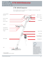
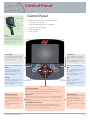
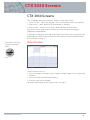
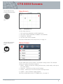
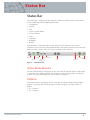
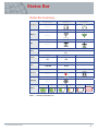
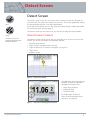
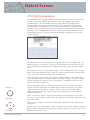
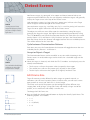
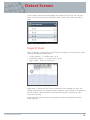
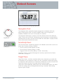
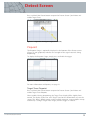
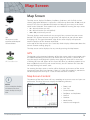
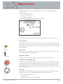
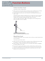
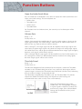
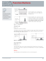
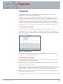
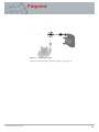
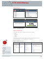
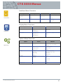
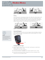
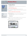
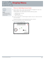
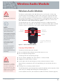
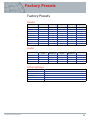
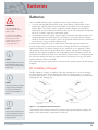
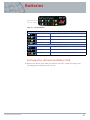
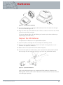
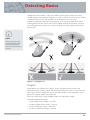
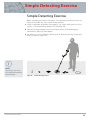
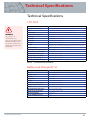


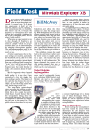


![1 Getting Zabbix [Zabbix]](http://vs1.manualzilla.com/store/data/005748780_1-c6fae7d52ae49b905c6dc80adee0ad61-150x150.png)