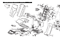
1
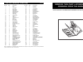
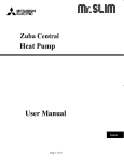
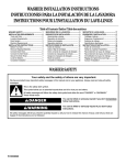
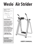
¨
Ordering Replacement Parts
If you encounter any difficulties with this product, or if you need to order replacement parts, write or call the
ICON Fitness Lifestyle Ltd. office at:
ICON Fitness Lifestyle Ltd.
Greenwich House
223 North Street
Sheepscar
West Yorkshire
Class HC Fitness Product
Tel: Country Code: 0345-089009
Fax: 0113-2411120
Model No. PERX31090
Serial No.
Please provide the following information when writing or calling:
The serial number can be found in
the location shown below. Write
the serial number in the space
above.
¥ The MODEL NUMBER of the product (PERX31090)
USERÕS MANUAL
¥ The NAME of the product (PROFORM RESTORATION 3100 massage chair)
¥ The SERIAL NUMBER of the product (see the front cover of this manual)
Serial
Number
Decal
(under seat)
¥ The KEY NUMBER and DESCRIPTION of the desired part(s) (see the PART LIST and EXPLODED DRAWING
in the centre of this manual).
QUESTIONS?
As a manufacturer, we are committed to providing complete
customer satisfaction. If you
have questions, or if there are
missing parts, we will guarantee
complete satisfaction through
our Customer Service Department.
Please CALL:
0345-089009
Or WRITE:
ICON Fitness Lifestyle Ltd.
Greenwich House
223 North Street
Sheepscar
West Yorkshire
Leeds LS7 2AA
CAUTION
PROFORM¨ is a registered trademark of ICON Health & Fitness, Inc.
Part No. 160155 R0100A
Printed in China © 1999 ICON Health & Fitness, Inc.
Read all precautions and instructions in this manual before
using this equipment. Save this
manual for future reference.
Patent
Pending
Visit our website at
www.proform.com
new products, prizes,
fitness tips, and much more!
¨
Notes
Table of Contents
Important Precautions . . . . . . . . . . . . . . . . . . . . . . . . . . . . . . . . . . . . . . . . . . . . . . . . . . . . . . . . . . . . . . . . . . . 3
Before You Begin . . . . . . . . . . . . . . . . . . . . . . . . . . . . . . . . . . . . . . . . . . . . . . . . . . . . . . . . . . . . . . . . . . . . . . 4
Assembly . . . . . . . . . . . . . . . . . . . . . . . . . . . . . . . . . . . . . . . . . . . . . . . . . . . . . . . . . . . . . . . . . . . . . . . . . . . . 5
How to Operate the Massage Chair . . . . . . . . . . . . . . . . . . . . . . . . . . . . . . . . . . . . . . . . . . . . . . . . . . . . . . . . . 7
Maintenance . . . . . . . . . . . . . . . . . . . . . . . . . . . . . . . . . . . . . . . . . . . . . . . . . . . . . . . . . . . . . . . . . . . . . . . . . 10
Notes . . . . . . . . . . . . . . . . . . . . . . . . . . . . . . . . . . . . . . . . . . . . . . . . . . . . . . . . . . . . . . . . . . . . . . . . . . . . . . .11
Ordering Replacement Parts . . . . . . . . . . . . . . . . . . . . . . . . . . . . . . . . . . . . . . . . . . . . . . . . . . . . . . Back Cover
Note: A PART LIST and an EXPLODED DRAWING are attached in the centre of this manual. Remove the PART
LIST and the EXPLODED DRAWING before beginning assembly.
2
11
HOW TO USE THE RECLINE CONTROL
HOW TO USE THE FOOTREST
To recline the chair, simply pull up on the recline
control on the right armrest. Lean back in the chair
until you have reached the desired position. Release
the recline control.
To extend the footrest, pull back on the footrest control
arm on the right side of the chair, until you feel the
control arm lock into place. The footrest will extend.
Important Precautions
WARNING: To reduce the risk of burns, fire, electric shock or serious injury to persons, read
all important precautions before using the massage chair.
READ AND FOLLOW ALL INSTRUCTIONS
Recline
Control
1. Read all precautions and instructions in this
manual before using the massage chair.
No other appliance should be on the same
circuit.
2. It is the responsibility of the owner to ensure
that all users of the massage chair are adequately informed of all precautions.
Footrest
Control Arm
To return the chair to the upright position, sit up in the
chair and pull up on the recline control. The chair back
will return to the upright position.
Footrest
To lower the footrest, simply push the control arm
forward.
9
10. Use the massage chair indoors. Never use the
massage chair outdoors.
WARNING
To reduce the risk of burns, fire, electric shock,
or injury to persons:
11. The massage chair is intended for home use
only. Do not use the massage chair in a commercial, rental or institutional setting.
3. Never leave the massage chair unattended
while it is plugged in.
DANGER
To reduce the risk of electric shock:
4. Close supervision is necessary when the
massage chair is used by, on, or near invalids
or disabled persons.
Maintenance
Check the massage chair periodically to make sure
that all parts are properly tightened.
¥ Is the hand control properly connected to the massage chair? (See assembly step 6 on page 6.)
If the hand control does not function properly, check
the following things:
The massage chair can be cleaned with a low-power
hand-held vacuum or a dry cloth. IMPORTANT: Never
use water or solvents to clean the massage chair.
¥ Is the power cord plugged into a 240-volt outlet?
¥ Is the power switch on the back of the chair in the
ÒONÓ position?
Keep the power cord away from heated surfaces.
12. Keep the power cord and the surge suppressor away from heated surfaces.
5. Keep children under the age of 12 away from
the massage chair.
13. Always turn off the hand control and unplug
the power cord from the outlet immediately
after using and before cleaning the massage
chair.
6. Use the massage chair only for its intended
use as described in this manual.
7. Never operate the massage chair if it is not
working properly, if it is damaged, or if the
power cord or plug is damaged. If any of
these conditions exists, please call the telephone number on the front of this manual.
DANGER
14. Keep pins and other sharp objects away from
the massage chair.
15. Carefully examine the massage chair before
each use. If there are any signs of deterioration, call the toll-free telephone number on the
front of this manual.
8. When connecting the power cord (see HOW
TO PLUG IN THE POWER CORD on page 7),
plug the power cord into an earthed circuit.
When replacing the fuse, only a ASTA
approved BS1362 type should be fitted to the
fuse carrier. A 13 amp fuse should be used.
16. Keep the massage chair dry, away from water
and moisture.
WARNING: Read all instructions before using this product. ICON assumes no responsibility
for personal injury or property damage sustained by or through the use of this product.
SAVE THESE INSTRUCTIONS
10
3
HOW TO USE THE MASSAGE ZONES
Before You Begin
Congratulations for selecting the PROFORM¨
RESTORATION 3100 massage chair. The innovative
RESTORATION 3100 massage chair is designed to
melt away stressÑrelaxing you, stimulating circulation
and reducing muscle fatigueÑany time you choose.
The convenient hand control allows you to choose
upper-back, lower-back or whole-back massage. You
can also choose between six massage programs.
questions, please call our Customer Service
Department at 0345-089009. To help us assist you,
please mention the product model number and serial
number when calling. The model number is
PERX31090. The serial number can be found on a
decal attached to the massage chair (see the front
cover of this manual for the location of the decal).
Before assembling the massage chair, please look at
the drawing below and familiarise yourself with the
parts that are labelled.
Please read this manual carefully before you use
the RESTORATION 3100. If you have additional
Headrest
On/off Switch
Circuit Breaker
(On the back)
Cover Pad
Armrest
Armrest
Recline Control
Footrest Control Arm
(On right side)
Hand Control Holder
(On both sides)
Hand Control
Footrest
4
also light. If the program you selected targets the
upper back, the upper back zone indicator will
also light. If the program you selected targets the
whole back, the whole back zone indicator will
also light.
The massage chair also features three massage
zones: upper back, lower back and whole back. The
massage zones are controlled with the Back Zones
button.
2. Once you have selected a program, sit back, relax
and enjoy the massage. You can change to a different program at any time.
1. Press the button once.
The indicator above
ÒwholeÓ will light, activating the whole massage zone. Press the
button again and the
indicator above ÒlowerÓ
will light, activating the
lower massage zone. Press the button again and
the indicator above ÒupperÓ will light, activating the
upper massage zone. Pressing the button again
will end the massage. Press the button once more
to reactivate the ÒwholeÓ massage zone.
The massage programs and their functions are:
LOWER BACK 1. This program offers a tenminute lower back massage.
UPPER BACK 2. This program offers a ten-minute
upper back massage.
WHOLE BACK 3. This program offers a tenminute massage of your whole back.
WHOLE BACK 4. This program offers a twentyminute massage of your whole back.
2. While you are using the
massage zones, you
can modify the intensity
of the massage by
using the Shiatsu button to select a soft or
firm massage.
WHOLE BACK 5. This program offers a twentyminute firm massage of your whole back.
WHOLE BACK 6. This program offers a twentyminute hard massage of your whole back.
Note: If no buttons on the hand control are
pressed while a program is running, the massage
chair will shut off once the program is finished.
To restart the massage action, simply press the power
button on the hand control and select the desired
massage option.
Note: The massage action will automatically stop
if no buttons on the hand control are pressed for
twenty minutes. This applies to both the manual
mode and the massage zones. To restart the massage action, simply press the power button on the
hand control and select the desired massage option.
HOW TO USE THE MASSAGE PROGRAMS
In addition to the manual mode and massage zones,
the massage chair offers six massage programs.
1. Press the
Program button
repeatedly to
select the
desired mode. A
program indicator will light to
show which program is selected. If the program you selected targets the
lower back, the
lower back zone
indicator will
9
DESCRIPTION OF THE HAND CONTROL
is lit, the massage mechanism will move up and
down, massaging your entire back. When the
ÒLowerÓ indicator is lit, the massage mechanism
will move up and down, massaging your lower
back. When the ÒUpperÓ indicator is lit, the massage mechanism will move up and down, massaging your upper back.
A
B
C
G. Program ButtonÑThis button selects the six programs.
D
H. Program IndicatorsÑThese will light to show
which program is selected.
E
F
FEATURES OF THE MASSAGE CHAIR
The convenient hand control lets you customise the
type of massage you get each time you use the
massage chair. In the manual mode, you can choose
any combination of upper-back, lower-back and
whole-back massage action. If desired, you can also
position the massage carriage to target a specific area
of your back for a specialised massage.
G
H
The control also offers six massage programs: 10Minute Lower Back, 10-Minute Upper Back, 10-Minute
Whole Back, 20-Minute Whole Back, 20-Minute Whole
BackÑFirm Massage and 20-Minute Whole
BackÑHard Massage.
HOW TO USE THE MANUAL MODE
When the power is turned on, the hand control will be
in the manual mode. The power indicator should be
the only indicator that is lit.
Assembly
Place all parts of the massage chair in a cleared area and remove the packing materials. Do not dispose of the
packing materials until the massage chair is fully assembled. Assembly requires only the included allen
wrench.
1. Feed the Recline Shock (20) and the attached cable
between the tubes on the Base (1) as shown.
1
5
Refer to the inset drawing. Remove the rubber
bands from the Bracket Screws (32) in the Base (1).
Make sure that the Arm Brackets (31) inside the tubes
are pressed against the indicated sides of the tubes.
7
Align the posts on the Right Armrest (5) with the
tubes on the Base (1). Slide the Right Armrest onto
the Base. Make sure that the posts are inside of
the tubes on the Base. In addition, make sure
that the cable is between the posts. Note: You
may need to flex the posts away from the Right
Side Shield (7) to slide the Right Armrest past
the Bracket Screws (32).
Posts
Cable
1
20
32
31
1
Top View
2. Tip the chair onto its right side. Remove the shipping
bracket from the Seat Frame (2) and the Back
Frame (4) by removing the Cotter Pins (26) and the
Hairpin Cotters (27). Save the Cotter Pins and the
Hairpin Cotters; you will need them for step 3.
2
27
27
2
4
26
A. Power IndicatorÑLights when the power is on.
1. Use the Carriage
Position buttons to
move the massage carriage to the location
you wish to massage.
B. Power ButtonÑTurns the power on and off.
C. Carriage Position ButtonsÑManually move the
massage mechanism up and down to target specific areas of the back for a localised massage.
2. Use the Shiatsu
Direction buttons to
begin massaging your
back. You may want to
try alternating the shiatsu directions during
your massage.
D. Shiatsu Direction Buttons and IndicatorsÑThese
buttons control the rotational direction of the massage when the Carriage Position Buttons (C) are
used.
E. Shiatsu Button and Soft and Firm IndicatorsÑThis
button selects either a soft or firm massage when
you are using the three massage zones.
3. If you like, you can use the Carriage Position buttons to move the carriage up and down during the
massage.
F. Back Zones Button and Whole, Lower, and Upper
IndicatorsÑThe Back Zones button selects the
three massage zones. When the ÒWholeÓ indicator
26
3. Attach the indicated end of the Recline Shock (20)
to the Back Frame (4) with a Cotter Pin (26) and a
Hairpin Cotter (27).
3
26
Shipping
Bracket
27
2
Attach the other end of the Recline Shock (20) to
the Seat Frame (2) with a Cotter Pin (26) and a
Hairpin Cotter (27). Make sure that the cable is
under the Recline Shock, as shown in the drawing. Note: You may need to raise the Back Frame
(4) to the upright position in order to attach the
Recline Shock.
Tip the chair back onto its base.
8
31
5
4
27
26
20
32
4. Refer to the inset drawing. Remove the rubber
bands from the Bracket Screws (32) in the left side
of the Base (1). Make sure that the Arm Brackets
(31) inside the tubes are pressed against the indicated sides of the tubes.
How to Operate the Massage Chair
4
13
HOW TO PLUG IN THE POWER CORD
Align the posts on the Left Armrest (6) with the tubes
on the Base (1). Slide the Left Armrest onto the
Base. Make sure that the posts are inside of the
tubes on the Base. Note: You may need to flex
the posts away from the Left Side Shield (8) to
slide the Left Armrest past the Bracket Screws
(32).
6
HOW TO TURN ON THE POWER
Make sure the power
switch on the back of the
chair is in the ÒonÓ position.
DANGER:
8
Attach the Pillow (13) to the fastener strip.
32
Improper connection of
the equipment-earthing conductor can result
in an increased risk of electric shock. Check
with a qualified electrician or serviceman if
you are in doubt as to whether the product is
properly grounded. Do not modify the plug
provided with the productÑif it will not fit the
outlet, have a proper outlet
installed by a qualified electrician.
Power Button
Next, press the power button on the hand control; an
indicator will light. Note: If
there is a thin sheet of
plastic on the face of the
hand control, remove it.
HOW TO TURN OFF THE POWER
1
31
32
5. Raise the footrest by pulling on the Footrest Control
Arm (23), shown in the inset drawing. Attach the
lower end of the Right Side Shield (7) to the right
side of the Base (1) with two Arm Cover Screws (35)
and two M6 Washers (95).
1
31 32
5
7
To turn off the power, press the power button on the
hand control. The power indicator will darken. Return
the power switch on the back of the chair to the ÒoffÓ
position.
32
95
32
Attach the lower end of the Left Side Shield (not
shown) to the left side of the Base (1) in the same
way.
This product must be earthed. If it should malfunction or break down, earthing provides a path of least
resistance for electric current to reduce the risk of
electric shock. Use this product with an equipmentearthing conductor and an earthing plug. Plug one
end of the cord into the massage chair. Plug the
power cord into an appropriate outlet that is properly installed and earthed in accordance with all
local codes and ordinances.
35
Use only a power cord type H05VV-F with a conductor
of at least 1mm2, with a country recognised plug and
an appliance coupler.
1
Using the included allen wrench, tighten the four
Bracket Screws (32) in the right side of the Base (1).
Tighten the four Bracket Screws (not shown) in the
left side of the Base (1).
Note: For clarity,
some parts of the
chair are not shown
23
6. Plug the cord from the Hand Control (22) into the
socket on the back of the massage chair. Make sure
to align the indicated tabs.
D
SE
FU
6
Tabs
22
Socket
6
7
Part ListÑModel No. PERX31090
Qty.
1
2
3
4
5
6
7
8
9
10
11
12
13
14
15
16
17
18
19
20
21
22
23
24
25
26
27
28
29
30
31
32
33
34
35
36
37
38
39
40
41
42
43
44
45
46
47
48
49
50
51
1
1
1
1
1
1
1
1
1
1
1
10
1
1
1
1
1
1
2
1
1
1
1
1
1
6
6
1
3
2
4
10
4
4
4
4
4
2
2
4
4
4
1
2
2
1
1
4
4
18
8
Description
Base
Seat Frame
Leg Frame
Back Frame
Right Armrest
Left Armrest
Right Side Shield
Left Side Shield
Right Panel
Left Panel
Seat Support
Support Hook
Pillow
Cover Pad
Chair Back Cover
Cover
Back Brace
Back Cover
Front Endcap
Recline Shock
Shock Actuator
Hand Control
Footrest Control Arm
Leg Link
Link Arm
Cotter Pin
Hairpin Cotter
Shock Nut
Set Screw
Seat Pin
Arm Bracket
Bracket Screw
Arm Screw
Arm Washer
Arm Cover Screw
Pad Frame Screw
Back Cover Screw
Straight Massage Arm
Rear Wheel
Short Massage Spacer
Long Massage Spacer
Massage Motor Nut
Massage Motor
Roll Pin
Short Massage Spring
Right Bent Massage Arm
Left Bent Massage Arm
Massage Roller
Massage Screw
Roller Washer
Roller Bolt
Key No.
Qty.
52
53
54
55
56
57
58
59
60
61
62
63
64
65
66
67
68
69
70
71
72
73
74
75
76
77
78
79
80
81
82
83
84
85
86
87
88
89
90
91
92
93
94
95
96
97
98
99
100
101
#
6
4
1
4
4
4
2
4
4
2
6
2
1
2
3
1
1
1
2
4
1
6
6
1
1
1
1
1
4
4
4
1
4
2
2
2
1
1
1
1
1
3
2
4
1
1
1
1
1
2
1
Description
Roller Nut
Spring Pin
Circuit Board
Board Spacer
Board Nut
Board Screw
Flat-sided Washer
Brace Washer
Brace Nut
Brace Screw
Wire Tie
Limit Switch
Four-wire Coil
Rear Wheel Axle
Black Jumper Wire
IEC Filter Socket
Power Switch
Circuit Breaker
Wire Mount
Bearing Screw
Sensor
Sensor Screw
Sensor Nut
Sensor Bracket
Motor
Fan
Drive Capacitor
Belt
Star Washer
Motor Washer
Motor Screw
Lift Assist Shock
Endcap Screw
Rear Endcap
Long Massage Spring
Seat Frame Endcap
Sensor Wire
Shiatsu Capacitor
Cover Bracket
Upper Switch Cover Bracket
Lower Switch Cover Bracket
Tec Screw
M8 Nut
M6 Washer
White Jumper Wire
Ground Wire
M3x14mm Screw
M3 Star Washer
M3 Nylon Nut
#6 x 1/2Ó Screw
UserÕs Manual
Note: Ò#Ó indicates a non-illustrated part. Specifications are subject to change without notice. To order replacement
parts, see the back cover of this manual.
REMOVE THIS PART LIST/EXPLODED
DRAWING FROM THE MANUAL
SAVE THIS PART LIST/EXPLODED DRAWING FOR FUTURE REFERENCE
81
Key No.
R0100A
Exploded
Chair DrawingÑModel No. PERX31090
R0100A
32
17
93
59 60
36
61 58
70
59 60
90
93
58
61
13
91
71 73
60
63
86
62
74
4
86
71
14
15
73
72
57
54
55
7
5
56
34
56
33
78
96
66
64
69
97
68
74
55
70
59
75
36
88
73
74
67
77
101
76
9
33
34
80
100 81
99
6
73
80
63
89
74
51 50
81
98 82
16
92
48
50 52
12
51
31
31
50
31
11
30
26
23
2
50
12
3
32
41
18
95
95
94
27 87
26
27
27
49
30
27
25
32
95 35
29
26
37
8
85
29
87
83
10
32
52
50
45
12
32
29
26
24
27
28
27
20
21
26
85
84
39
65
1
19
37
84
43
52 53
47
50
50
48
40 42
84
19
26
95
50
50
48
53 50
52
50
41 53
51
52
49
40 50
38
50
46
44
42 45
53
44
38
79
22
48
50
51