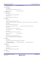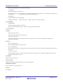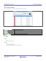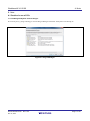
1
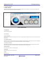
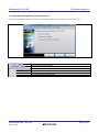
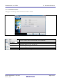
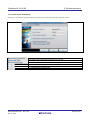
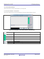
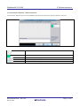
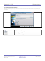
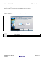
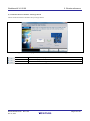
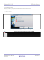
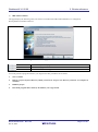
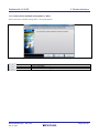
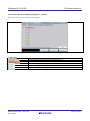
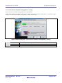
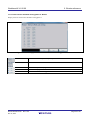
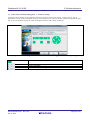
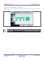
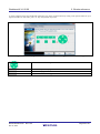
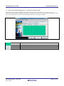
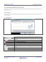
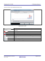
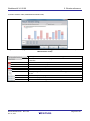
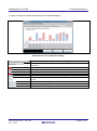
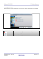
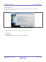
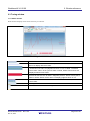
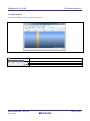
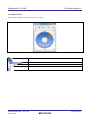
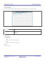
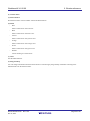
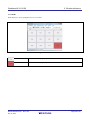
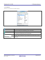
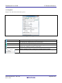
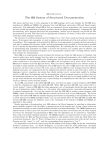
User’s Manual
Workbench6 V1.02.00
Integrated Development Environment for R-touch
User’s Manual
Target Device
RX Family
RX Family
All information contained in these materials, including products and product specifications,
represents information on the product at the time of publication and is subject to change by
Renesas Electronics Corp. without notice. Please review the latest information published by
Renesas Electronics Corp. through various means, including the Renesas Electronics Corp.
website (http://www.renesas.com).
www.renesas.com
Rev.1.00 Nov 2014
Notice
1.
Descriptions of circuits, software and other related information in this document are provided only to illustrate the operation
of semiconductor products and application examples. You are fully responsible for the incorporation of these circuits,
software,and information in the design of your equipment. Renesas Electronics assumes no responsibility for any losses
incurred by you or third parties arising from the use of these circuits, software, or information.
2. Renesas Electronics has used reasonable care in preparing the information included in this document, but Renesas Electronics
does not warrant that such information is error free. Renesas Electronics assumes no liability whatsoever for any damages
incurred by you resulting from errors in or omissions from the information included herein.
3.
Renesas Electronics does not assume any liability for infringement of patents, copyrights, or other intellectual property rights
of third parties by or arising from the use of Renesas Electronics products or technical information described in this document.
No license, express, implied or otherwise, is granted hereby under any patents, copyrights or other intellectual property rights
of Renesas Electronics or others.
4. You should not alter, modify, copy, or otherwise misappropriate any Renesas Electronics product, whether in whole or in part.
Renesas Electronics assumes no responsibility for any losses incurred by you or third parties arising from such alteration,
modification, copy or otherwise misappropriation of Renesas Electronics product.
5. Renesas Electronics products are classified according to the following two quality grades: “Standard” and “High Quality”.
The recommended applications for each Renesas Electronics product depends on the product’s quality grade, as indicated
below.
“Standard”: Computers; office equipment; communications equipment; test and measurement equipment; audio and visual
equipment; home electronic appliances; machine tools; personal electronic equipment; and industrial robots etc.
“High Quality”: Transportation equipment (automobiles, trains, ships, etc.); traffic control systems; anti-disaster systems; antcrime systems; and safety equipment etc.
Renesas Electronics products are neither intended nor authorized for use in products or systems that may pose a direct threat
to human life or bodily injury (artificial life support devices or systems, surgical implantations etc.), or may cause serious
property damages (nuclear reactor control systems, military equipment etc.). You must check the quality grade of each
Renesas Electronics product before using it in a particular application. You may not use any Renesas Electronics product for
any application for which it is not intended. Renesas Electronics shall not be in any way liable for any damages or losses
incurred by you or third parties arising from the use of any Renesas Electronics product for which the product is not intended
by Renesas Electronics.
6. You should use the Renesas Electronics products described in this document within the range specified by Renesas
Electronics, especially with respect to the maximum rating, operating supply voltage range, movement power voltage range,
heat radiation characteristics, installation and other product characteristics. Renesas Electronics shall have no liability for
malfunctions or damages arising out of the use of Renesas Electronics products beyond such specified ranges.
7. Although Renesas Electronics endeavors to improve the quality and reliability of its products, semiconductor products have
specific characteristics such as the occurrence of failure at a certain rate and malfunctions under certain use conditions.
Further, Renesas Electronics products are not subject to radiation resistance design. Please be sure to implement safety
measures to guard them against the possibility of physical injury, and injury or damage caused by fire in the event of the
failure of a Renesas Electronics product, such as safety design for hardware and software including but not limited to
redundancy, fire control and malfunction prevention, appropriate treatment for aging degradation or any other appropriate
measures. Because the evaluation of microcomputer software alone is very difficult, please evaluate the safety of the final
products or systems manufactured by you.
8. Please contact a Renesas Electronics sales office for details as to environmental matters such as the environmental
compatibility of each Renesas Electronics product. Please use Renesas Electronics products in compliance with all applicable
laws and regulations that regulate the inclusion or use of controlled substances, including without limitation, the EU RoHS
Directive. Renesas Electronics assumes no liability for damages or losses occurring as a result of your noncompliance with
applicable laws and regulations.
9. Renesas Electronics products and technology may not be used for or incorporated into any products or systems whose
manufacture, use, or sale is prohibited under any applicable domestic or foreign laws or regulations. You should not use
Renesas Electronics products or technology described in this document for any purpose relating to military applications or use
by the military, including but not limited to the development of weapons of mass destruction. When exporting the Renesas
Electronics products or technology described in this document, you should comply with the applicable export control laws and
regulations and follow the procedures required by such laws and regulations.
10. It is the responsibility of the buyer or distributor of Renesas Electronics products, who distributes, disposes of, or otherwise
places the product with a third party, to notify such third party in advance of the contents and conditions set forth in this
document, Renesas Electronics assumes no responsibility for any losses incurred by you or third parties as a result of
unauthorized use of Renesas Electronics products.
11. This document may not be reproduced or duplicated in any form, in whole or in part, without prior written consent of Renesas
Electronics.
12. Please contact a Renesas Electronics sales office if you have any questions regarding the information contained in this
document or Renesas Electronics products, or if you have any other inquiries.
(Note 1) “Renesas Electronics” as used in this document means Renesas Electronics Corporation and also includes its
majority-owned subsidiaries.
(Note 2) “Renesas Electronics product(s)” means any product developed or manufactured by or for Renesas Electronics.
(2012.4)
How to Use This Manual
This manual describes the role of the Workbench6 integrated development environment for developing applications and
systems for RH850 family, RX family, and RL78 family, and provides an outline of its features.
Workbench6 is an integrated development environment (IDE) for RH850 family, RX family, and RL78 family, integrating
the necessary tools for the development phase of software (e.g. design, implementation, and debugging) into a single
platform.
By providing an integrated environment, it is possible to perform all development using just this product, without the need
to use many different tools separately.
Readers
This manual is intended for users who wish to understand the functions of the CS+ and
design software and hardware application systems.
Purpose
This manual is intended to give users an understanding of the functions of the CS+ to use
for reference in developing the hardware or software of systems using these devices.
Organization
This manual can be broadly divided into the following units.
How to Read This Manual
It is assumed that the readers of this manual have general knowledge of electricity, logic
circuits, and microcontrollers.
Conventions
Data significance:
Higher digits on the left and lower digits on the right
Active low representation:
XXX (overscore over pin or signal name)
Note:
Footnote for item marked with Note in the text
Caution:
Information requiring particular attention
Remarks:
Supplementary information
Numeric representation:
Decimal ... XXXX
Hexadecimal ... 0xXXXX
All trademarks and registered trademarks are the property of their respective owners.
Table of Contents
1. Summary............................................................................................................................................ 1
1.1 System Requirements ..................................................................................................................................................... 1
1.2 Other installation files ..................................................................................................................................................... 1
1.2.1 Supported Integrated Development Environment .................................................................................................. 1
1.2.2 Run-time library ..................................................................................................................................................... 1
1.2.3 .NET Framework .................................................................................................................................................... 1
2. Window reference.............................................................................................................................. 1
2.1 Main window .................................................................................................................................................................. 1
2.1.1 Menu bar ................................................................................................................................................................ 1
2.1.2 Tool bar .................................................................................................................................................................. 3
2.1.3 Window display area .............................................................................................................................................. 4
2.1.4 Status bar ................................................................................................................................................................ 4
2.2 First step guide ................................................................................................................................................................ 5
2.2.1 Start page................................................................................................................................................................ 5
2.2.2 Integrated development environment selection ...................................................................................................... 6
2.2.3 Touch MCU selection ............................................................................................................................................ 7
2.2.4 Touch sensor CPU setting ...................................................................................................................................... 8
2.2.5 Touch sensor measurement method selection ........................................................................................................ 9
2.2.6 Touch interface definition .................................................................................................................................... 10
2.2.7 Project store directory selection ........................................................................................................................... 12
2.2.8 Dumping resistance selection ............................................................................................................................... 13
2.2.9 Target board preparation ...................................................................................................................................... 14
2.2.10 Target board startup ........................................................................................................................................... 16
2.2.11 Touch sensor automatic tuning phase 1 - Start ................................................................................................... 18
2.2.12 Touch sensor automatic tuning phase 1 - Result ................................................................................................ 19
2.2.13 Touch sensor automatic tuning phase 2 - Start ................................................................................................... 20
2.2.14 Touch sensor automatic tuning phase 2 - Tuning ............................................................................................... 21
2.2.15 Touch sensor automatic tuning phase 2 - Result ................................................................................................ 22
2.2.16 Touch sensor automatic tuning phase 3.............................................................................................................. 23
2.2.17 Touch sensor automatic tuning phase 3 - Result ................................................................................................ 32
2.2.18 Target board reboot ............................................................................................................................................ 43
2.3 Tuning window ............................................................................................................................................................. 45
2.3.1 Status monitor ...................................................................................................................................................... 45
2.3.2 Slider monitor....................................................................................................................................................... 47
2.3.3 Wheel monitor ...................................................................................................................................................... 49
2.3.4 Difference monitor ............................................................................................................................................... 51
2.3.5 Locus monitor ...................................................................................................................................................... 53
2.3.6 Measurements ...................................................................................................................................................... 54
2.3.7 Radar .................................................................................................................................................................... 56
2.3.8 Parameters ............................................................................................................................................................ 58
2.3.9 Registers ............................................................................................................................................................... 62
2.4 Adjustment guide .......................................................................................................................................................... 67
2.5 Source code gallery....................................................................................................................................................... 67
2.6 Document manager ....................................................................................................................................................... 68
2.6.1 Menu .................................................................................................................................................................... 68
3. FAQ ................................................................................................................................................... 1
3.1 First step guide displays “Could not load or assembly ‘ISWrapper.dll’ or one of its dependencies” in “Target board
startup”.................................................................................................................................................................................. 1
3.2 Status monitor does not display the Reference value and the Threshold count value. .................................................... 1
4. Note ................................................................................................................................................... 1
4.1 Caution in use of CS+ ..................................................................................................................................................... 1
4.1.1 Enabling IronPython Console Plug-in .................................................................................................................... 1
4.2 Caution in use of e2 studio.............................................................................................................................................. 2
4.2.1 First step guide does not reply to your operation in “Target board startup”........................................................... 2
Revision Record ..................................................................................................................................... 3
Workbench6 V1.02.00
1. Summary
1. Summary
1.1 System Requirements
System requirements for Workbench are as follows.
Table 1-1Supported OS
OS
Windows Vista (32 bit, 64 bit)
Windows 7 (32 bit, 64 bit)
Windows 8 (32 bit, 64 bit)
Remarks
1.2 Other installation files
1.2.1 Supported Integrated Development Environment
Workbench supports Renesas electronics CS+ and e2 studio.
Table 1-2 Supported Integrated Development Environment
Integrated Development Environment
Renesas electronics CS+
Renesas electronics e2 studio
Version
V.3.00.00 or later
V3.1.0.24 or later
Remarks
Administrator right is necessary to enable
Integration Service.
1.2.2 Run-time library
Workbench needs Visual studio 2012 Run-time library (x86). Even if you use 64 bit OS (e.g. Windows 7 64 bit),
Workbench needs Visual studio 2012 Run-time library for 32 bit.
1.2.3 .NET Framework
Workbench needs Microsoft .NET framework 4.0.
R01UH0001EJ0100
Nov 14, 2014
Rev.1.00
Page 1 of 81
Workbench6 V1.02.00
2. Window reference
2. Window reference
2.1 Main window
This is the start-up window that opens when Workbench is launched. In this window, you can start First step guide and
touch sensor monitoring tools, touch sensor tuning tools.
Figure 2-1 Main window
2.1.1 Menu bar
This menu displays menus.
(1) Connection
(a) CS+ connection
Workbench starts connection with target board via CS+. If “Open” dialog is displayed, select a CS+ project file and press
[OK] button.
(b) e2 studio connection
Workbench starts connection with target board via e2 studio. If “e2 studio Project / Workspace setup” dialog is displayed,
select a e2 studio project folder and e2 studio workspace folder and press [OK] button.
(c) Serial port connection
Workbench starts connection with target board via serial port. If “Setup Serial port” dialog is displayed, select a serial
port number connecting your target board and serial port baudrate and press [OK] button.
(d) Disconnection
Workbench ends connection with target board.
(e) Close All
Workbench closes all tools in window area.
(f) Exit
Workbench exits.
R01UH0001EJ0100
Nov 14, 2014
Rev.1.00
Page 1 of 81
Workbench6 V1.02.00
2. Window reference
(2) View
(a) Tool bar
Shows and hides tool bar.
(a) Status bar
Shows and hides status bar
(3) Capacitive touch
(a) Status monitor
Start Status monitor.
(a) Slider monitor
Start Slider monitor.
(b) Wheel monitor
Start Wheel monitor.
(c) Difference monitor
Start Difference monitor.
(d) Locus monitor
Start Locus monitor.
(e) Measurement view
Start Measurements.
(f) Radar view
Start Radar.
(g) Touch board
Start Touch board.
(h) Touch API Parameters
Start Touch API Parameters
(i) Touch API Registers
Start Touch API Registers.
(j) Start monitor
Start the monitoring to touch sensor on target board.
(k) Stop monitor
Stop the monitoring to touch sensor on target board.
(4) Tools
(a) Navigator
Start Navigator.
(a) First step guide
Start First step guide.
R01UH0001EJ0100
Nov 14, 2014
Rev.1.00
Page 2 of 81
Workbench6 V1.02.00
2. Window reference
(b) Adjustment guide
Start Adjustment guide. Workbench does not support this function now.
(c) Tuning window
Start Tuning window.
(d) Source gallery
Start Source gallery. Workbench does not support this function now.
(e) Document manager
Start Document manager.
(f) Option
Starts Option. Workbench does not support this function now.
(g) Log play
Start the playing touch log file. If “Open” dialog is displayed, select a touch log file and press [OK] button.
(h) Log stop
Stop the playing or recoding touch log file.
(i) Log pause
Suspend the playing touch log file.
(j) Log record
Start the recording touch log file. If “Save As” dialog is displayed, select a touch log file and press [OK] button.
(5) Window
(6) Help
(a) About Workbench
Display Workbench version information.
2.1.2 Tool bar
This toolbar shows command buttons.
R01UH0001EJ0100
Nov 14, 2014
Rev.1.00
Page 3 of 81
Workbench6 V1.02.00
2. Window reference
Workbench starts connection with target board via serial port. If “Setup Serial
port” dialog is displayed, select a serial port number and serial port baudrate
and press [OK] button.
Workbench ends connection with target board.
Starts Touch API Parameters.
Starts Touch API Registers.
Starts Status monitor.
Starts Slider monitor.
Starts Wheel monitor.
Starts Option.
Starts First step guide.
Starts Adjustment guide.
Starts Tuning window.
Starts monitoring touch sensor on target board.
Stop the monitoring touch sensor on target board.
Starts the playing touch log file.
Stops the playing touch log file.
Suspend the playing touch log file.
Starts the recording touch log file.
2.1.3 Window display area
Touch sensor monitoring tools and Touch sensor tuning tools are displayed in this area.
2.1.4 Status bar
This displays status of connection between Workbench and target board and status of touch log file.
Displays status of connection between Workbench and target board.
- Non connection: Workbench does not connect with target board.
- Connected(CS+): Workbench connects with target board via CS+.
- Connected(e2 studio): Workbench connects with target board via e2
studio.
- Connected(Serial port): Workbench connects with target board via serial
port.
Displays status of touch log file.
- Log stop: Workbench does not play or record touch log file.
- Log play: Workbench is playing touch log file.
- Log pause: Workbench is suspending the playing touch log file.
- Log record: Workbench is recording touch log file.
R01UH0001EJ0100
Nov 14, 2014
Rev.1.00
Page 4 of 81
Workbench6 V1.02.00
2. Window reference
2.2 First step guide
First step guide generates the best program for the user’s touch sensor microcontroller and guides automatic tuning of
touch sensor sensitivity.
2.2.1 Start page
This is the start page of the First step guide. Press [Next] button.
Figure 2-2 First step guide – Start page
Cannot press this button.
To the next page.
Terminates the First step guide.
R01UH0001EJ0100
Nov 14, 2014
Rev.1.00
Page 5 of 81
Workbench6 V1.02.00
2. Window reference
2.2.2 Integrated development environment selection
Select the Integrated development environment (hereinafter called IDE) and whether to use emulator or not.
Figure 2-3 First step guide – Integrated development environment selection
Use CS+ with emulator.
Use e2 studio with emulator
Use e2 studio without emulator.
Back to the previous page.
To the next page.
Terminates the First step guide.
R01UH0001EJ0100
Nov 14, 2014
Rev.1.00
Page 6 of 81
Workbench6 V1.02.00
2. Window reference
2.2.3 Touch MCU selection
This page is for selecting a touch sensor microcontroller to be used.
Figure 2-4 First step guide – Touch MCU selection
A series of touch sensor microcontroller can be selected.
A group of touch sensor microcontroller can be selected.
A part number of touch sensor microcontroller can be selected.
Displays the number of touch sensors of the touch sensor microcontroller
selected at Series, Group, and Part No.
Back to the previous page.
To the next page.
Terminates the First step guide.
R01UH0001EJ0100
Nov 14, 2014
Rev.1.00
Page 7 of 81
Workbench6 V1.02.00
2. Window reference
2.2.4 Touch sensor CPU setting
This page is for selecting operating frequencies of the touch sensor microcontroller and touch sensors.
Figure 2-5 First step guide – Touch sensor CPU setting
A count source can be selected.
Frequency of the selected count source can be set.
A count source of CTSU can be selected.
Back to the previous page.
To the next page.
Terminates the First step guide.
R01UH0001EJ0100
Nov 14, 2014
Rev.1.00
Page 8 of 81
Workbench6 V1.02.00
2. Window reference
2.2.5 Touch sensor measurement method selection
This page is for selecting touch detection method of the touch sensors.
Figure 2-6 First step guide – Touch sensor measurement method selection
Self-capacitance is selected as touch detection method.
Mutual capacitance is selected as touch detection method.
Back to the previous page.
To the next page.
Terminates the First step guide.
R01UH0001EJ0100
Nov 14, 2014
Rev.1.00
Page 9 of 81
Workbench6 V1.02.00
2. Window reference
2.2.6 Touch interface definition
Layout touch interfaces according to touch interfaces on your target board.
(1) Touch interface definition – Self-capacitance
Touch interface definition that you selected self-capacitance as touch sensor detection method is as follows.
Figure 2-7 First step guide - Touch interface definition - Self-capacitance
This is canvas that touch keys, sliders and wheels are laid out.
Lays out a touch key on the canvas.
Lays out a slider (horizontal) on the canvas.
Lays out a slider (vertical) on the canvas.
Lays out a wheel on the canvas.
Back to the previous page.
To the next page.
Terminates the First step guide.
R01UH0001EJ0100
Nov 14, 2014
Rev.1.00
Page 10 of 81
Workbench6 V1.02.00
2. Window reference
(2) Touch interface definition – Mutual capacitance
Touch interface definition that you selected Mutual capacitance as touch sensor detection method is as follows.
Figure 2-8 First step guide – Touch interface definition – Mutual capacitance
This is canvas that touch keys, sliders and wheels are laid out.
Lays out a matrix key on the canvas.
Back to the previous page.
To the next page.
Terminates the First step guide.
R01UH0001EJ0100
Nov 14, 2014
Rev.1.00
Page 11 of 81
Workbench6 V1.02.00
2. Window reference
2.2.7 Project store directory selection
This page is for selecting a directory to store a set of software for the touch sensor microcontroller corresponding to the
selected IDE.
Figure 2-9 First step guide – Project store directory selection
Displays an absolute path of the folder.
Starts “Folder browser dialogue.
Back to the previous page.
To the next page.
Terminates the First step guide.
R01UH0001EJ0100
Nov 14, 2014
Rev.1.00
Page 12 of 81
Workbench6 V1.02.00
2. Window reference
2.2.8 Dumping resistance selection
This page is for setting dumping resistance values of the touch sensor microcontroller.
Figure 2-10 First step guide – Dumping resistance selection
A dumping resistance value for all TS can be set collectively.
A dumping resistance value for each TS can be set respectively.
Back to the previous page.
To the next page.
Terminates the First step guide.
R01UH0001EJ0100
Nov 14, 2014
Rev.1.00
Page 13 of 81
Workbench6 V1.02.00
2. Window reference
2.2.9 Target board preparation
This page is provided for guiding setup of the board with the touch sensor microcontroller.
(1)
Connection between PC and emulator
Check connection between your PC and emulator. This guide is not displayed when Workbench recognized connection
between PC and emulator.
Figure 2-11 First step guide – Connection between PC and emulator
Back to the previous page.
To the next page.
Terminates the First step guide.
R01UH0001EJ0100
Nov 14, 2014
Rev.1.00
Page 14 of 81
Workbench6 V1.02.00
2. Window reference
(1) Connection between emulator and target board
Check connection between emulator and your target board.
Figure 2-12 First step guide – Connection between emulator and target board
Back to the previous page.
To the next page.
Terminates the First step guide.
R01UH0001EJ0100
Nov 14, 2014
Rev.1.00
Page 15 of 81
Workbench6 V1.02.00
2. Window reference
2.2.10 Target board startup
This page is provided for guiding startup of the board with the touch sensor microcontroller.
(1)
IDE with emulator
Figure 2-13 First step guide – Target board startup
Shows a process on the right side of this icon was completed.
Shows a process on the right side of this icon was not completed.
Back to the previous page.
To the next page.
Terminates the First step guide.
R01UH0001EJ0100
Nov 14, 2014
Rev.1.00
Page 16 of 81
Workbench6 V1.02.00
(2)
2. Window reference
IDE without emulator
This page displays the following when you selected “e2 studio with USB (without Emulator)” in “Integrated
Development Environment selection”.
Figure 2-14 First step guide - IDE without emulator
Back to the previous page.
To the next page.
Terminates the First step guide.
User must generate a program and starts your target board. The procedures are as follows.
1.
Start e2 studio.
2.
Import a project output in directory which you choose in “Project store directory selection” to workspace of
e2 studio.
3.
Build the project.
4.
Download program that is made by the build to your target board.
R01UH0001EJ0100
Nov 14, 2014
Rev.1.00
Page 17 of 81
Workbench6 V1.02.00
2. Window reference
2.2.11 Touch sensor automatic tuning phase 1 - Start
Starts touch sensor automatic tuning phase 1. Press [Next] button.
Figure 2-15 First step guide – Touch sensor automatic tuning phase 1
Back to the previous page.
To the next page.
Terminates the First step guide.
R01UH0001EJ0100
Nov 14, 2014
Rev.1.00
Page 18 of 81
Workbench6 V1.02.00
2. Window reference
2.2.12 Touch sensor automatic tuning phase 1 - Result
Show result of touch sensor automatic tuning phase 1.
Figure 2-16 First step guide – Touch sensor automatic tuning phase1 - Result
Parasitic capacitance of TS is normal.
This is Warning to the Parasitic capacitance of TS.
This is Error to the Parasitic capacitance of TS.
Back to the previous page.
To the next page.
Terminates the First step guide.
R01UH0001EJ0100
Nov 14, 2014
Rev.1.00
Page 19 of 81
Workbench6 V1.02.00
2. Window reference
2.2.13 Touch sensor automatic tuning phase 2 - Start
Starts touch sensor automatic tuning phase 2.Press [Next] button.
Figure 2-17 First step guide – Touch sensor automatic tuning phase 2 - Start
Back to the previous page.
To the next page.
Terminates the First step guide.
R01UH0001EJ0100
Nov 14, 2014
Rev.1.00
Page 20 of 81
Workbench6 V1.02.00
2. Window reference
2.2.14 Touch sensor automatic tuning phase 2 - Tuning
Starts touch sensor automatic tuning phase 2.Press [Next] button.
Touch sensor automatic tuning phase 2 is in progress. When touch sensor automatic tuning phase 2 is finished, this page
change to “Touch sensor automatic tuning phase 2 – Result” automatically.
Figure 2-18 First step guide – Touch sensor automatic tuning phase 2 - Tuning
Back to the previous page.
Cannot press this button.
Terminates the First step guide.
R01UH0001EJ0100
Nov 14, 2014
Rev.1.00
Page 21 of 81
Workbench6 V1.02.00
2. Window reference
2.2.15 Touch sensor automatic tuning phase 2 - Result
Display result of touch sensor automatic tuning phase 2
Figure 2-19 First step guide – Touch sensor automatic tuning phase 2 - Result
Show sensor drive pulse frequency.
Show sensor offset value.
Back to the previous page.
To the next page.
Terminates the First step guide.
R01UH0001EJ0100
Nov 14, 2014
Rev.1.00
Page 22 of 81
Workbench6 V1.02.00
2. Window reference
2.2.16 Touch sensor automatic tuning phase 3
(1) Self-capacitance
Starts touch sensor automatic tuning phase 3. Press [Next] button.
Figure 2-20 First step guide – Touch sensor automatic tuning phase 3 - Start
Back to the previous page.
To the next page.
Terminates the First step guide.
R01UH0001EJ0100
Nov 14, 2014
Rev.1.00
Page 23 of 81
Workbench6 V1.02.00
2. Window reference
(a) Touch sensor automatic tuning phase 3 – Touch key tuning
Touch key with TS number is surrounded by red frame is an object of sensitivity tuning. At first, push “Y” key on
keyboard of your PC while touching the touch key with a finger well or with an iron stick. Afterwards repeat three times
that “Y” key on keyboard of your PC while touching the touch key with a finger commonly.
Figure 2-21 First step guide – Touch sensor automatic tuning phase 3- Touch key tuning
Shows touch key for tuning.
Back to the previous page.
To the next page.
Terminates the First step guide.
R01UH0001EJ0100
Nov 14, 2014
Rev.1.00
Page 24 of 81
Workbench6 V1.02.00
2. Window reference
(a) Touch sensor automatic tuning – Slider and Wheel checking
Before sensitive tuning of slider and wheel, Workbench checks the status of all sliders and wheels. This check starts by
press “Y” key on keyboard of your PC. In addition, you must not touch sliders and wheels during this check.
Figure 2-22 First step guide – Touch sensor automatic tuning – Slider and Wheel checking
Back to the previous page.
To the next page.
Terminates the First step guide.
R01UH0001EJ0100
Nov 14, 2014
Rev.1.00
Page 25 of 81
Workbench6 V1.02.00
2. Window reference
(b) Touch sensor automatic tuning phase 3 – Slider tuning
After the check of sliders and wheels, Workbench starts sensitivity tuning of the sliders by pushing “Y” key on keyboard
of your PC.
Figure 2-23 First step guide – Touch sensor automatic tuning phase 3 – Slider tuning start
Back to the previous page.
To the next page.
Terminates the First step guide.
R01UH0001EJ0100
Nov 14, 2014
Rev.1.00
Page 26 of 81
Workbench6 V1.02.00
2. Window reference
A slider composed of TS surrounded with red frame is an object of slider sensitivity tuning. After sliding the slider on
your target board three or four times, press “Y” key on keyboard of your PC.
Figure 2-24 First step guide – Touch sensor automatic tuning phase 3 –slider tuning
Shows a slider for tuning.
Back to the previous page.
To the next page.
Terminates the First step guide.
R01UH0001EJ0100
Nov 14, 2014
Rev.1.00
Page 27 of 81
Workbench6 V1.02.00
2. Window reference
(c) Touch sensor automatic tuning phase 3 – Wheel tuning
After the check of sliders and wheels or sensitivity tuning of slider, Workbench starts sensitivity tuning of the wheels by
pushing “Y” key on keyboard of your PC.
Figure 2-25 First step guide – Touch sensor automatic tuning phase 3 – Wheel tuning start
Back to the previous page.
To the next page.
Terminates the First step guide.
R01UH0001EJ0100
Nov 14, 2014
Rev.1.00
Page 28 of 81
Workbench6 V1.02.00
2. Window reference
A wheel composed of TS surrounded with red frame is an object of wheel sensitivity tuning. After spin the wheel on your
target board three or four times, press “Y” key on keyboard of your PC.
Figure 2-26 First step guide – Touch sensor automatic tuning phase 3 – Wheel tuning
Shows a wheel for tuning.
Back to the previous page.
To the next page.
Terminates the First step guide.
R01UH0001EJ0100
Nov 14, 2014
Rev.1.00
Page 29 of 81
Workbench6 V1.02.00
2. Window reference
(2) Mutual capacitance
Starts touch sensor automatic tuning phase 3. Press [Next] button.
Figure 2-27 First step guide – Touch sensor automatic tuning phase 3 – Mutual capacitance - Start
Back to the previous page.
To the next page.
Terminates the First step guide.
R01UH0001EJ0100
Nov 14, 2014
Rev.1.00
Page 30 of 81
Workbench6 V1.02.00
2. Window reference
(a) Touch sensor automatic tuning phase 3 – Matrix key sensitivity tuning
Matrix key with TS number surrounded by red frame is an object of sensitivity tuning. At first, push “Y” key on
keyboard of your PC while touching the matrix key with a finger well or with an iron stick. Afterwards repeat three times
that “Y” key on keyboard of your PC while touching the matrix key with a finger commonly.
Figure 2-28 First step guide – Touch sensor automatic tuning phase 3 – Matrix key tuning
Shows matrix key for tuning.
Back to the previous page.
To the next page.
Terminates the First step guide.
R01UH0001EJ0100
Nov 14, 2014
Rev.1.00
Page 31 of 81
Workbench6 V1.02.00
2. Window reference
2.2.17 Touch sensor automatic tuning phase 3 - Result
Shows result of touch sensor automatic tuning phase 3. Press [Next] button to output the result of touch sensor automatic
tuning to source files.
(1) Self-capacitance
Display the result of touch sensor automatic tuning phase 3 with following six kinds when touch sensor detection method
is self-capacitance.
(a) Capacitance value
Figure 2-29 First step guide – Touch sensor automatic tuning phase 3 - Capacitance value
Change the result of touch sensor automatic tuning phase 3.
Select the number of TS to display to a window with 12 channels or with all
channels.
Show Capacitance of the maximum sensitive.
Show Capacitance of Touch.
Show Capacitance of Non-touch.
Shows Capacitance of the offset.
Show Threshold count value.
Select TS to retry touch sensor automatic tuning phase 3.
Press [Retry] to execute touch sensor automatic tuning phase 3 if TS to retry
is set.
Back to the previous page.
To the next page.
Terminates the First step guide.
R01UH0001EJ0100
Nov 14, 2014
Rev.1.00
Page 32 of 81
Workbench6 V1.02.00
2. Window reference
(a) Sensor Counter value (without Measurement count)
Figure 2-30 First step guide - Touch sensor automatic tuning phase 3 - Sensor Counter value (without
Measurement count)
Change the result of touch sensor automatic tuning phase 3.
Select the number of TS to display to a window with 12 channels or with all
channels.
Show Capacitance of the maximum sensitive.
Show Capacitance of Touch.
Show Capacitance of Non-touch.
Show Threshold count value.
Select TS to retry touch sensor automatic tuning phase 3.
Press [Retry] to execute touch sensor automatic tuning phase 3 if TS to retry
is set.
Back to the previous page.
To the next page.
Terminates the First step guide.
R01UH0001EJ0100
Nov 14, 2014
Rev.1.00
Page 33 of 81
Workbench6 V1.02.00
2. Window reference
(b) Sensor Counter value (include Measurement count)
Figure 2-31 First step guide - Touch sensor automatic tuning phase 3 - Sensor Counter value (include
Measurement count)
Change the result of touch sensor automatic tuning phase 3.
Select the number of TS to display to a window with 12 channels or with all
channels.
Show Capacitance of the maximum sensitive.
Show Capacitance of Touch.
Show Capacitance of Non-touch.
Show Threshold count value.
Select TS to retry touch sensor automatic tuning phase 3.
Press [Retry] to execute touch sensor automatic tuning phase 3 if TS to retry
is set.
Back to the previous page.
To the next page.
Terminates the First step guide.
R01UH0001EJ0100
Nov 14, 2014
Rev.1.00
Page 34 of 81
Workbench6 V1.02.00
2. Window reference
(c) Sensor Counter value (include Measurement count / Expansion display)
Figure 2-32 First step guide - Touch sensor automatic tuning phase 3 - Sensor Counter value (include
Measurement count / Expansion display)
Change the result of touch sensor automatic tuning phase 3.
Select the number of TS to display to a window with 12 channels or with all
channels.
Show Capacitance of the maximum sensitive.
Show Capacitance of Touch.
Show Capacitance of Non-touch.
Show Threshold count value.
Select TS to retry touch sensor automatic tuning phase 3.
Press [Retry] to execute touch sensor automatic tuning phase 3 if TS to retry
is set.
Back to the previous page.
To the next page.
Terminates the First step guide.
R01UH0001EJ0100
Nov 14, 2014
Rev.1.00
Page 35 of 81
Workbench6 V1.02.00
2. Window reference
(d) Measurement time
Figure 2-33 First step guide - Touch sensor automatic tuning phase 3 - Measurement time
Change the result of touch sensor automatic tuning phase 3.
Select the number of TS to display to a window with 12 channels or with all
channels.
Show Measurement time.
Show total time of Measurement time.
Select TS to retry touch sensor automatic tuning phase 3.
Press [Retry] to execute touch sensor automatic tuning phase 3 if TS to retry
is set.
Back to the previous page.
To the next page.
Terminates the First step guide.
R01UH0001EJ0100
Nov 14, 2014
Rev.1.00
Page 36 of 81
Workbench6 V1.02.00
2. Window reference
(e) Slider / Wheel threshold
Figure 2-34 First step guide - Touch sensor automatic tuning phase 3 – Slider / Wheel threshold
Change the result of touch sensor automatic tuning phase 3.
Select the number of TS to display to a window with 12 channels or with all
channels.
Show Threshold of Slider or Wheel.
Select TS to retry touch sensor automatic tuning phase 3.
Press [Retry] to execute touch sensor automatic tuning phase 3 if TS to retry
is set.
Back to the previous page.
To the next page.
Terminates the First step guide.
R01UH0001EJ0100
Nov 14, 2014
Rev.1.00
Page 37 of 81
Workbench6 V1.02.00
2. Window reference
(2) Mutual capacitance
Display the result of touch sensor automatic tuning phase 3 with following five kinds when touch sensor detection
method is mutual capacitance.
(a) Capacitance ratio
Figure 2-35 First step guide - Touch sensor automatic tuning phase 3 - Capacitance value
Change the result of touch sensor automatic tuning phase 3.
Select the number of TS to display to a window with 12 channels or with all
channels.
Show the inter electrode capacitance decrease value in the max load touch.
Show the inter-electrode capacitance decrease value in the normal touch.
Show Inter-electrode capacitance.
Show Parasitic capacitance.
Show Offset value
Show Threshold count value.
Select TS to retry touch sensor automatic tuning phase 3.
Press [Retry] to execute touch sensor automatic tuning phase 3 if TS to retry
is set.
Back to the previous page.
To the next page.
Terminates the First step guide.
R01UH0001EJ0100
Nov 14, 2014
Rev.1.00
Page 38 of 81
Workbench6 V1.02.00
2. Window reference
(a) Sensor Counter value (without Measurement count)
Figure 2-36 First step guide - Touch sensor automatic tuning phase 3 - Sensor Counter value (without
Measurement count)
Change the result of touch sensor automatic tuning phase 3.
Select the number of TS to display to a window with 12 channels or with all
channels.
Show the inter electrode capacitance decrease value in the max load touch.
Show the inter-electrode capacitance decrease value in the normal touch.
Show Inter-electrode capacitance.
Show Threshold count value.
Select TS to retry touch sensor automatic tuning phase 3.
Press [Retry] to execute touch sensor automatic tuning phase 3 if TS to retry
is set.
Back to the previous page.
To the next page.
Terminates the First step guide.
R01UH0001EJ0100
Nov 14, 2014
Rev.1.00
Page 39 of 81
Workbench6 V1.02.00
2. Window reference
(b) Sensor Counter value (include Measurement count)
Figure 2-37 First step guide - Touch sensor automatic tuning phase 3 - Sensor Counter value (include
Measurement count)
Change the result of touch sensor automatic tuning phase 3.
Select the number of TS to display to a window with 12 channels or with all
channels.
Show the inter electrode capacitance decrease value in the max load touch.
Show the inter-electrode capacitance decrease value in the normal touch.
Show Inter-electrode capacitance.
Show Threshold count value.
Select TS to retry touch sensor automatic tuning phase 3.
Press [Retry] to execute touch sensor automatic tuning phase 3 if TS to retry
is set.
Back to the previous page.
To the next page.
Terminates the First step guide.
R01UH0001EJ0100
Nov 14, 2014
Rev.1.00
Page 40 of 81
Workbench6 V1.02.00
2. Window reference
(c) Sensor Counter value (include Measurement count / Expansion display)
Figure 2-38 First step guide - Touch sensor automatic tuning phase 3 - Sensor Counter value (include
Measurement count / Expansion display)
Change the result of touch sensor automatic tuning phase 3.
Select the number of TS to display to a window with 12 channels or with all
channels.
Show the inter electrode capacitance decrease value in the max load touch.
Show the inter-electrode capacitance decrease value in the normal touch.
Show Inter-electrode capacitance.
Show Threshold count value.
Select TS to retry touch sensor automatic tuning phase 3.
Press [Retry] to execute touch sensor automatic tuning phase 3 if TS to retry
is set.
Back to the previous page.
To the next page.
Terminates the First step guide.
R01UH0001EJ0100
Nov 14, 2014
Rev.1.00
Page 41 of 81
Workbench6 V1.02.00
2. Window reference
(d) Measurement time
Figure 2-39 First step guide – Touch sensor automatic tuning phase 3 - Measurement time
Change the result of touch sensor automatic tuning phase 3.
Select the number of TS to display to a window with 12 channels or with all
channels.
Show Measurement time.
Show total time of Measurement time.
Select TS to retry touch sensor automatic tuning phase 3.
Press [Retry] to execute touch sensor automatic tuning phase 3 if TS to retry
is set.
Back to the previous page.
To the next page.
Terminates the First step guide.
R01UH0001EJ0100
Nov 14, 2014
Rev.1.00
Page 42 of 81
Workbench6 V1.02.00
2. Window reference
2.2.18 Target board reboot
This page builds source file that is updated by the result of touch sensor automatic tuning and reboot your target board.
(1) IDE with Emulator
Figure 2-40 First step guide – Target board reboot
Shows a process on the right side of this icon was completed.
Shows a process on the right side of this icon was not completed.
Back to the previous page.
To the next page.
Terminates the First step guide.
R01UH0001EJ0100
Nov 14, 2014
Rev.1.00
Page 43 of 81
Workbench6 V1.02.00
2. Window reference
(2) IDE without Emulator
This page displays the following when you selected “e2 studio with USB (without Emulator)” in “Integrated
Development Environment selection”.
Figure 2-41 First step guide – IDE without emulator
User must generate a program and starts your target board. The procedures are as follows.
5.
Start e2 studio.
6.
Build the project.
7.
Download program that is made by the build to your target board.
R01UH0001EJ0100
Nov 14, 2014
Rev.1.00
Page 44 of 81
Workbench6 V1.02.00
2. Window reference
2.3 Tuning window
2.3.1 Status monitor
Status monitor displays touch sensor sensitivity in real time.
Figure 2-42 Status monitor
Shows count value.
Show reference value. When TS is a part of slider or wheel, Status monitor
does not display reference value.
Shows Threshold count value for judgment of touch or not. Hereinafter the
“Threshold count value for judgment of touch no not” is called “Threshold
count value”. When TS is a part of slider or wheel, Status monitor does not
display threshold count value.
Show result of Judgment process for touch or not. Hereinafter the “Judgment
process for touch or not” is called “Judgment process”. When TS is a part of
slider or wheel, Status monitor does not display judgment touch or not.
Show numerical value of count value and reference count value, threshold
count value.
Show grid line.
Show the value of count value on grid line.
R01UH0001EJ0100
Nov 14, 2014
Rev.1.00
Page 45 of 81
Workbench6 V1.02.00
2. Window reference
(1) Context menu
(a) TS Select
Select a TS number to monitor in Status monitor.
(a) Display
-
Numerical value
Show and hide numerical value of count value and reference value, threshold count value.
-
Scale
Shows and hides the value of count value on grid line.
-
Zoom in
Enlarge view area.
-
Zoom out
Reduce view area.
-
Up
Push upward view area.
-
Down
Push downward view area.
(b) Close
Exit Status monitor.
(2) Shortcut key
(a) Ctrl + “+”
Enlarge view area.
(a) Ctrl + “-“
Reduce view area.
(b) Ctrl + “Up”, Ctrl + “PageUp”
Push upward view area.
(c) Ctrl + “Down”, Ctrl + “PageDown”
Push downward view area.
R01UH0001EJ0100
Nov 14, 2014
Rev.1.00
Page 46 of 81
Workbench6 V1.02.00
2. Window reference
2.3.2 Slider monitor
Slider monitor displays slider touch position in real time.
Figure 2-43 Slider monitor
Shows slider touch position.
Shows numerical value of slider touch position.
Shows TS number composing a slider.
Shows slider resolution.
R01UH0001EJ0100
Nov 14, 2014
Rev.1.00
Page 47 of 81
Workbench6 V1.02.00
2. Window reference
(1) Context menu
(a) Slider select
Select a slider to monitor in Slider monitor.
(a) Display
-
Touch position
Shows and hides numerical value of slider touch position.
-
Resolution
Shows and hides slider resolution.
-
TS number
Shows and hides TS number composing a slider.
(b) Setup
-
Horizontal
Change slider image to horizontal.
-
Vertical
Change slider image to vertical.
-
Forward order
Change slider layout order of slider TS forward.
-
Backward order
Change slider layout order of slider backward.
(c) Close
Exit Slider monitor.
R01UH0001EJ0100
Nov 14, 2014
Rev.1.00
Page 48 of 81
Workbench6 V1.02.00
2. Window reference
2.3.3 Wheel monitor
Wheel monitor displays wheel touch position in real time.
Figure 2-44 Wheel monitor
Shows wheel touch position.
Shows numerical value of wheel touch position.
Shows TS number composing a wheel.
Shows wheel resolution.
R01UH0001EJ0100
Nov 14, 2014
Rev.1.00
Page 49 of 81
Workbench6 V1.02.00
2. Window reference
(1) Context menu
(a) Wheel select
Select a wheel to monitor in Wheel monitor.
(a) Display
-
Touch position
Shows and hides numerical value of wheel touch position.
-
Resolution
Shows and hides wheel resolution.
-
TS number
Shows and hides TS number composing a wheel.
(b) Setup
-
Forward order
Change the wheel layout order of wheel TS. When “Forward order” is checked, Wheel monitor changes the wheel
layout order forward. When “Forward order” is not checked, Wheel monitor changes the layout wheel layout order
backward.
-
Rotate clockwise
Rotate the start position of wheel TS clockwise
-
Rotate counter-clockwise
Rotate wheel TS start position counter-clockwise.
(c) Close
Exit Wheel monitor.
R01UH0001EJ0100
Nov 14, 2014
Rev.1.00
Page 50 of 81
Workbench6 V1.02.00
2. Window reference
2.3.4 Difference monitor
Difference monitor displays count value difference in real time.
Figure 2-45 Difference monitor
Shows count value difference. When TS is a part of slider or wheel,
Difference monitor does not display reference value.
Shows Y-axis value.
Shows TS number.
R01UH0001EJ0100
Nov 14, 2014
Rev.1.00
Page 51 of 81
Workbench6 V1.02.00
2. Window reference
(1) Context menu
(a) TS select
-
Next channels
Change TS numbers to monitor in Difference monitor according to following order.
TS00 – TS11、TS12 – TS23、TS24 – TS35
-
Previous channels
Change TS number to monitor in Difference monitor in order of reverse of “Next channels”.
(a) Display
-
Difference count value
Shows and hides numerical value of difference count value.
-
TS number
Shows and hides TS number.
-
Y-Axis
Shows and hides Y-Axis.
(b) Close
Exit Difference monitor.
R01UH0001EJ0100
Nov 14, 2014
Rev.1.00
Page 52 of 81
Workbench6 V1.02.00
2. Window reference
2.3.5 Locus monitor
Locus monitor displays slider touch position and wheel touch position in the form of line graph in real time.
Figure 2-46 Locus monitor
Shows slider touch position or wheel touch position.
Shows the value of vertical axis of a slider touch position or wheel touch
position
(1) Context menu
(a) Interface select
-
Slider
Select a slider to monitor in Locus monitor.
-
Wheel
Select a wheel to monitor in Locus monitor.
(a) Close
Exit Locus monitor.
R01UH0001EJ0100
Nov 14, 2014
Rev.1.00
Page 53 of 81
Workbench6 V1.02.00
2. Window reference
2.3.6 Measurements
Measurements displays count value and reference value, threshold count value, result of judgment in real time.
Figure 2-47 Measurements
Shows TS number.
Shows count value.
Shows reference count value. When TS is a part of slider or wheel,
Measurements displays 65535 as the “Reference count value”.
Show threshold count value. When TS is a part of slider or wheel,
Measurements display 65535 as the “Threshold count value”.
Shows result of the “Judgment process” as follows.
Touch: On, Non-touch
R01UH0001EJ0100
Nov 14, 2014
Rev.1.00
Page 54 of 81
Workbench6 V1.02.00
2. Window reference
(1) Context menu
(a) Status monitor
Start Status monitor with TS number selected in Measurements.
(b) Mark
-
Red
Mark a selected row with red color.
-
Blue
Mark a selected row with blue color.
-
Yellow
Mark a selected row with yellow color.
-
Orange
Mark a selected row with orange color.
-
Green
Mark a selected row with green color.
-
Default
Cancel marking of a selected row.
(c) Close
Exit the Measurements.
(2) Drag and drop
You can change TS number which the Status monitor is monitoring by drag and drop TS number selecting in the
Measurements into the Status monitor.
R01UH0001EJ0100
Nov 14, 2014
Rev.1.00
Page 55 of 81
Workbench6 V1.02.00
2. Window reference
2.3.7 Radar
Radar displays a result of judgment process in real time.
Figure 2-48 Radar
Shows result of judgment process is non-touch.
Shows result of judgment process is touch.
R01UH0001EJ0100
Nov 14, 2014
Rev.1.00
Page 56 of 81
Workbench6 V1.02.00
2. Window reference
(1) Context menu
(a) Status monitor
Select a TS number to monitor in Status monitor.
(a) Mark
-
Red
Mark a selected row with red color.
-
Blue
Mark a selected row with blue color.
-
Yellow
Mark a selected row with yellow color.
-
Orange
Mark a selected row with orange color.
-
Green
Mark a selected row with green color.
-
Default
Cancel marking of a selected row.
(b) Setup
-
TS00 – TS11
Change TS numbers to monitor in Radar to TS00 - TS11.
-
TS12 – TS23
Change TS numbers to monitor in Radar to TS12 – TS23.
-
TS24 – TS35
Change TS numbers to monitor in Radar to TS24 – TS35.
(c) Close
Exit Radar.
(2) Drag and drop
You can change TS number which the Status monitor is monitoring by drag and drop TS number selecting in the
Measurements into the Status monitor.
R01UH0001EJ0100
Nov 14, 2014
Rev.1.00
Page 57 of 81
Workbench6 V1.02.00
2. Window reference
2.3.8 Parameters
Parameters can read and edit TouchAPI parameters.
Figure 2-49 Parameters
Reads TouchAPI parameters from target board.
Reads TouchAPI parameters from parameter file. Select parameter file in
“Open file” dialog that is displayed by press of this button.
Writes TouchAPI parameters to target board.
Writes TouchAPI parameters to parameter file. Select parameter file in “Save
file” dialog that is displayed by press of this button.
Writes TouchAPI parameters to TouchAPI source files. When “Folder
browser” dialog is displayed, select a folder that TouchAPI project is stored.
Shows “Description area” that explains about a selected Touch API
parameter.
R01UH0001EJ0100
Nov 14, 2014
Rev.1.00
Page 58 of 81
Workbench6 V1.02.00
2. Window reference
(1) TouchAPI parameters
(a) Drift correction
-
Enable
Enabling and disabling the Drift correction.
True: enable, False: disable
-
Interval
Set interval time for the Drift correction.
(a) Continual touch limiter
-
Enable
Enabling and disabling the “Max successive ON count”.
True: enable, False: disable
-
Value
Set the “execution interval time” for the “Max successive ON count”.
(b) Response delay time to touch
-
Enable
Enabling and disabling the “Judging count non-touch to touch”.
True: enable, False: disable
-
Non-touch -> Touch
Set a value of “Judging count non-touch to touch”.
(c) Response delay time to non-touch
-
Enable
Enabling and disabling the “Judging count touch to non-touch”.
True: enable, False: disable
-
Touch -> Non-touch
Set a value of “Judging count touch to non-touch”
(d) Multi touch canceller
-
Enable
Enabling and disabling the “Multi touch canceller”.
True: enable, False: disable
-
Start channel
Set “Start TS number” that multi touch canceller effects.
-
Stop channel
Set the “Stop TS number” that multi touch canceller effects.
-
Threshold
Set the “Threshold” of the “Multi touch canceller”.
R01UH0001EJ0100
Nov 14, 2014
Rev.1.00
Page 59 of 81
Workbench6 V1.02.00
2. Window reference
(e) Threshold
Set the “Threshold count value”. Number in “[]” shows TS number.
(f) Hysteresis
Set the “Hysteresis”. Number in “[ ]” shows TS number.
(g) Slider parameter
-
Resolution
Set the “Slider resolution”. Number in “[ ]” shows TS number.
-
Threshold
Set the “Slider threshold”. Number in “[ ]” shows TS number.
(h) Wheel parameter
-
Resolution
-
Set the “Wheel resolution”. Number in “[ ]” shows TS number.
-
Threshold
Set the “Wheel resolution”. Number in “[ ]” shows TS number.
(2) Context menu
(a) Read
-
Read from target system
Read TouchAPI parameters from target board.
-
Read from parameter file
Read TouchAPI parameters from parameter file. Select a parameter file in “Open file” dialog that is displayed by
selection of this menu.
(a) Write
-
Write to target system
Write TouchAPI parameters to target board.
-
Write to parameter file
Write TouchAPI parameters to parameter file. Select a parameter file in “Save file” dialog that is displayed by
selection of this menu.
-
Write to Touch API
Write TouchAPI parameters to TouchAPI source files. When “Folder browser” dialog is displayed, select a folder
that TouchAPI project is stored.
(b) Initialize
Initialize TouchAPI parameters.
(c) Auto update
Enabling and disabling automatic update of Touch API parameters.
(d) Display description
Shows and hides the “Description area”.
(e) Close
Exit Parameters.
R01UH0001EJ0100
Nov 14, 2014
Rev.1.00
Page 60 of 81
Workbench6 V1.02.00
R01UH0001EJ0100
Nov 14, 2014
Rev.1.00
2. Window reference
Page 61 of 81
Workbench6 V1.02.00
2. Window reference
2.3.9 Registers
Registers can read and edit TouchAPI registers.
Figure 2-50 Registers
Reads TouchAPI registers from target board.
Reads TouchAPI registers from parameter file. Select register file in “Open
file” dialog that is displayed by press of this button.
Writes TouchAPI registers to target board.
Writes TouchAPI registers to register file. Select register file in “Save file”
dialog that is displayed by press of this button.
Writes TouchAPI registers to TouchAPI source files. When “Folder browser”
dialog is displayed, select a folder that TouchAPI project is stored.
Shows “Description area” that explains about a selected Touch API register.
R01UH0001EJ0100
Nov 14, 2014
Rev.1.00
Page 62 of 81
Workbench6 V1.02.00
2. Window reference
(1) TouchAPI registers
(a) CTSUCR0
-
CTSUSTRT
Show “CTSU Measurement Operation Start”.
Stop: Measurement operation stops,
-
Start: Measurement operation starts
CTSUCAP
Show “CTSU Measurement Operation Start Trigger Select”.
SoftwareTrigger: Software trigger, ExternalTrigger:
-
External trigger
CTSUSNZ
Show “CTSU Wait State Power-Saving Enable”.
Disable: Power-saving function during wait state is disabled
Enable: Power-saving function during wait state is enabled
-
CTSUIOC
Show “CTSU Transmit Pin Control”.
Low: Low-level output from transmit channel non-measurement pin
High: High-level output from transmit channel non-measurement pin
-
CTSUINIT
Show “CTSU Control Block Initialization”.
This value is always “Off”.
(a) CTSUCR1
-
CTSUPON
Show “CTSU Power Supply Enable”.
Off: Powered off
On: Powered on
-
CTSUSCW
Show “CTSU LPF Capacitance Charging Control”.
Off: Capacitance switch turned off,
-
On: Capacitance switch turned on
CTSUATUNE0
Show “CTSU LPF Capacitance Charging Control”.
NormalOperation: Normal operating mode
LowVoltage: Low-voltage operating mode
-
CTSUATUNE1
Show “CTSU Power Supply Capacity Adjustment”.
NormalOutput: Normal output,
-
HighCurrentOutput: High-current output
CTSUCLK
Show “CTSU Operating Clock Select”.
PCLK: PCLK、LPCLKdividedBy2: KCLK/2、PCLKdividedBy4: CKLK/4
R01UH0001EJ0100
Nov 14, 2014
Rev.1.00
Page 63 of 81
Workbench6 V1.02.00
-
2. Window reference
CTSUMD
Show “CTSU Measurement Mode Select“.
SelfCapacitanceSingleScan: Self-capacitance single scan mode
SelfCapacitanceMultiScan: Self-capacitance multi-scan mode
MutualCapcitanceSimpleScan: Mutual capacitance simple scan mode
MutualCapcitanceFullScan: Mutual capacitance full scan mode
(b) CTSUSDPRS
-
CTSUPRRATIO
Show “CTSU Measurement Time and Pulse Count Adjustment CTSU”.
-
CTSUPRMODE
Show “CTSU Base Period and Pulse Count Setting”.
Pulse510: 510 pulses,
-
Pulse126: 126 pulses,
Pulse62: 62 pulses
CTSUSOFF
Show “CTSU High-Pass Noise Reduction Function Off Setting”.
Off: High-pass noise reduction function turned on,
Off: High-pass noise reduction function turned off
(c) CTSUSST
-
CTSUSST
-
Show “CTSU Sensor Stabilization Wait Control”.
(d) CTSUMCH0
-
CTSUMCH0
Show “CTSU Measurement Channel 0”.
CTSUTS0: TS0、CTSUTS1: TS1、CTSUST2: TS2、…
(e) CTSUMCH1
-
CTSUMCH1
Show “CTSU Measurement Channel 1”.
CTSUTS0: TS0、CTSUTS1: TS1、CTSUST2: TS2、…
(f) CTSUCHAC0
-
CTSUCHAC0
Show “CTSU Channel Enable Control 0”.
GPIO: Not measurement target,
CapacitiveTouch: Measurement target
(g) CTSUCHAC1
-
CTSUCHAC1
Show “CTSU Channel Enable Control 1”.
GPIO: Not measurement target,
CapacitiveTouch: Measurement target
(h) CTSUCHTRC0
-
CTSUCHTRC0
Show “CTSU Channel Transmit/Receive Control 0”.
R01UH0001EJ0100
Nov 14, 2014
Rev.1.00
Page 64 of 81
Workbench6 V1.02.00
Receive: Reception,
2. Window reference
Transmit: Transmission
(i) CTSUCHTRC1
-
CTSUCHTRC1
Show “CTSU Channel Transmit/Receive Control 1”.
Receive: Reception,
Transmit: Transmission
(j) CTSUDCLKC
-
CTSUSSMOD
Show “CTSU Diffusion Clock Mode Select”.
-
CTSUCCCNT
Show “CTSU Diffusion Clock Control”.
(k) CTSUST
-
CTSUSTC
Show “CTSU Measurement Status Counter”.
Status0: Status0、Status1: Status1、Status2: Status2、Status3: Status3、Status4: Status4、Status5: Status5
-
CTSUDTSR
Show “CTSU Data Transfer Status Flag”.
False: Measurement result has been read,
-
True: “Measurement result has not been read”
CTSUSOVF
Show “CTSU Sensor Counter Overflow Flag”.
True: No overflow,
-
False: An overflow
CTSUROVF
Show “CTSU Reference Counter Overflow Flag”.
True: No overflow,
-
False: An overflow
CTSUPS
Show “CTSU Mutual Capacitance Status Flag”.
First: First measurement, Second: Second measurement
(l) CTSUSSC
-
CTSUSSDIV
Show “CTSU Spectrum Diffusion Frequency Division Setting”.
DivideBy1: Divided by 1,
DiviceBy16: Divided by 16
DivideBy2: Divided by 2,
DivideBy3: Divided by 3,
-,
(m) CTSUSO0
-
CTSUSO
Show “CTSU Sensor Offset Adjustment”.
-
CTSUSNUM
Show “CTSU Measurement Count Setting”
(n) CTSUSO1
-
CTSURICOA
R01UH0001EJ0100
Nov 14, 2014
Rev.1.00
Page 65 of 81
Workbench6 V1.02.00
2. Window reference
Show “CTSU Reference ICO Current Adjustment”.
-
CTSUSDPA
Show “CTSU Base Clock Setting”.
DivideBy2: Operating clock divided by 2、DivideBy4: Operating clock divided by 4、DivideBy6: Operating clock
divided by 6, - - DiviceBy64: Operating clock divided by 64
-
CTSUICOG
Show “CTSU ICO Gain Adjustment”.
Gain100: 100% gain,
Gain66: 66% gain,
Gain50: 50% gain,
Gain40: 40% gain
(o) CTSUERRS
-
CTSUICOMP
Shows “TSCAP Voltage Error Monitor”
Normal: Normal TSCAP voltage, Abnormal: Abnormal TSCAP voltage,
(2) Context menu
(a) Read
-
Read from target system
Read TouchAPI registers from target board.
-
Read from register file
Read TouchAPI registers from register file. Select a register file in “Open file” dialog that is displayed by
selection of this menu.
(b) Write
-
Write to target system
Write TouchAPI registers to target board.
-
Write to register file
Write TouchAPI registers to register file. Select a register file in “Save file” dialog that is displayed by selection of
this menu.
-
Write to Touch API
Write TouchAPI registers to TouchAPI source files. When “Folder browser” dialog is displayed, select a folder
that TouchAPI project is stored.
(c) Initialize
Initialize TouchAPI registers.
(d) Auto update
Enabling and disabling automatic update of Touch API parameters.
(e) Display description
Shows and hides the “Description area”
(f) Close
Exit Registers.
R01UH0001EJ0100
Nov 14, 2014
Rev.1.00
Page 66 of 81
Workbench6 V1.02.00
2. Window reference
2.4 Adjustment guide
Workbench does not support this function now.
2.5 Source code gallery
Workbench does not support this function now.
R01UH0001EJ0100
Nov 14, 2014
Rev.1.00
Page 67 of 81
Workbench6 V1.02.00
2. Window reference
2.6 Document manager
Document manager can read and search documents about touch sensor.
Figure 2-51 Document manager
Input keyword to search.
Start searching keyword.
Stop searching keyword.
Clear result of searching keyword.
Enabling and disabling cache for searching keyword.
Show progress of searching keyword.
2.6.1 Menu
(1) File
-
Exit
Exit Document manager.
(2) Help
-
About Document manager
Display Document manager version information.
R01UH0001EJ0100
Nov 14, 2014
Rev.1.00
Page 68 of 81
Workbench6 V1.02.00
3. FAQ
3. FAQ
3.1 First step guide displays “Could not load or assembly ‘ISWrapper.dll’ or one of its
dependencies” in “Target board startup”
Install Visual studio 2012 Run-time library for 32 bit to your PC. Even if you use 64 bit OS, you must install the Visual
studio run-time library for 32 bit.
3.2 Status monitor does not display the Reference value and the Threshold count
value.
When TS is a part of slider or wheel, Status monitor does not display threshold count value.
R01UH0001EJ0100
Nov 14, 2014
Rev.1.00
Page 1 of 81
Workbench6 V1.02.00
4. Note
4. Note
4.1 Caution in use of CS+
4.1.1 Enabling IronPython Console Plug-in
Press menu [Tool] – [Plug-in Setting] to start the Plug-in Manager and enable “IronPython Console Plug-in”.
Figure 4-1 Plug-in Manager
R01UH0001EJ0100
Nov 14, 2014
Rev.1.00
Page 1 of 81
Workbench6 V1.02.00
4. Note
4.2 Caution in use of e2 studio
4.2.1 First step guide does not reply to your operation in “Target board startup”
When the model number of the microcomputer on target board does not accord with the model number of the
microcomputer which you chose, "Target board startup" may not reply to your operation.
Please terminate e2 studio in this case.
R01UH0001EJ0100
Nov 14, 2014
Rev.1.00
Page 2 of 81
Revision Record
Description
Rev.
1.0
Date
Nov 14, 2014
Page
-
Summary
First Edition issued
Workbench6 V1.02.00 User’s Manual
Publication Date:
Rev.1.00
Nov 14, 2014
Published by:
Renesas Electronics Corporation
http://www.renesas.com
SALES OFFICES
Renesas Electronics America Inc.
2801 Scott Boulevard Santa Clara, CA 95050-2549, U.S.A.
Tel: +1-408-588-6000, Fax: +1-408-588-6130
Renesas Electronics Canada Limited
1101 Nicholson Road, Newmarket, Ontario L3Y 9C3, Canada
Tel: +1-905-898-5441, Fax: +1-905-898-3220
Renesas Electronics Europe Limited
Dukes Meadow, Millboard Road, Bourne End, Buckinghamshire, SL8 5FH, U.K
Tel: +44-1628-585-100, Fax: +44-1628-585-900
Renesas Electronics Europe GmbH Arcadiastrasse 10, 40472 Düsseldorf, Germany Tel:
+49-211-6503-0, Fax: +49-211-6503-1327
Renesas Electronics (China) Co., Ltd.
Room 1709, Quantum Plaza, No.27 ZhiChunLu Haidian District, Beijing 100191, P.R.China
Tel: +86-10-8235-1155, Fax: +86-10-8235-7679
Renesas Electronics (Shanghai) Co., Ltd.
Unit 301, Tower A, Central Towers, 555 Langao Road, Putuo District, Shanghai, P. R. China 200333
Tel: +86-21-2226-0888, Fax: +86-21-2226-0999
Renesas Electronics Hong Kong Limited
Unit 1601-1613, 16/F., Tower 2, Grand Century Place, 193 Prince Edward Road West, Mongkok, Kowloon, Hong Kong
Tel: +852-2265-6688, Fax: +852 2886-9022/9044
Renesas Electronics Taiwan Co., Ltd.
13F, No. 363, Fu Shing North Road, Taipei 10543, Taiwan
Tel: +886-2-8175-9600, Fax: +886 2-8175-9670
Renesas Electronics Singapore Pte. Ltd.
80 Bendemeer Road, Unit #06-02 Hyflux Innovation Centre, Singapore 339949
Tel: +65-6213-0200, Fax: +65-6213-0300
Renesas Electronics Malaysia Sdn.Bhd.
Unit 906, Block B, Menara Amcorp, Amcorp Trade Centre, No. 18, Jln Persiaran Barat, 46050 Petaling Jaya, Selangor Darul Ehsan, Malaysia
Tel: +60-3-7955-9390, Fax: +60-3-7955-9510
Renesas Electronics Korea Co., Ltd.
12F., 234 Teheran-ro, Gangnam-Ku, Seoul, 135-920, Korea
Tel: +82-2-558-3737, Fax: +82-2-558-5141
© 2014 Renesas Electronics
Corporation.
All rights reserved.
Colophon 3.0
Workbench6 V01.02.00
R01UH0001EJ0100