1
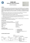
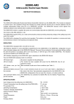
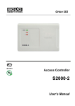
5 WARRANTY S2000-KPB 5.1 Manufacturer warrants its S2000-KPB module to be in conformance with specification under normal EXECUTIVE MODULE transportation, storage, mounting and maintenance. Version 1.08 User’s Manual 5.2 The average operating life of S2000-KPB module is at least 10 years. 5.3 Manufacturer warrants its product to be free from defects in materials and workmanship for 18 months since putting the S2000-KPB into operation, but no more then 24 months since production under normal use and ISO 9001 service. ББ02 УП001 1 TECHNICAL DESCRIPTION 5.4 Sending off the module to the manufacturer for repairing apply it with the damage certificate describing the defect. Send your complaints to the manufacturer at the following address: 1.1.1 The S2000-KPB executive module (hereinafter referred to as module) is designed to operate as a part of ZAO NVP BOLID integrated fire safety and security ORION system, manufactured by BOLID Company, under control of S2000- #4, Pionerskaya street, Korolyov, Moscow Region, Russia, 141070 ASPT panel, or C2000(ver.1.12+)/C2000M console, or PC supplied by any version of ARM Orion. S2000-KPB Tel./fax +7 495 513-32-35, +7 495 516-93-72. module is used to implement fire alarm and extinguishing, access control and video surveillance functions. E-mail: [email protected], Web-site: http://www.bolid.com. 1.1.2 The S2000-KPB module is designed to control lamps, sirens, video cameras, electromagnetic locks and automatic systems for gas, powder or aerosol fire fighting. 6 ACCEPTANCE CERTIFICATE 1.1.3 The module has to be located within protected premises near the driven devices. The module is designed S2000-KPB Executive Module Product Designation 1.1 General for round-the-clock operation. Serial Number 1.1.4 The module is not meant for use in corrosion or dust ambient conditions or in explosive premises. 1.1.5 The module is designed to operate under following ambient conditions: Produced, tested by quality control department in compliance with state standards and specifications, packed by – operating temperatures from -30°С to +50°C; NVP BOLID Company and qualified as deliverable. – relative humidity up to 98% (for 25°C) non-condensing; – vibration load from 1 to 35 Hz, with maximum acceleration of 0,5 g. Q.C. STAMP _____________________ Name ____________________________ Date 1.2 Specifications 1.2.1 Power supply − external d.c. from 10,2 V up to 28,4 V 1.2.2 Number of power inputs −2 (RIP-12, RIP-24) 1.2.3 Power Consumption, max 1.2.4 Current Consumption (without −3W regard to − 130 mА under 12 V power supplying; executive devices), no more than − 70 mА under 24 V power supplying 1.2.5 Current Consumption in OPERATING mode − 45 mА under 12 V power supplying; (with all outputs being switched OFF), no more than − 25 mА under 24 V power supplying 1.2.6 Number of outputs −6 – commuting voltage − from 10,2 up to 28,4 V (from module’s power) – commuting output current, no more than −2А – circuit failure monitoring current, no more than − 1,5 мА 1.2.7 Number of inputs for automatic extinguishing − 2 system status monitoring 1.2.8 Overall dimensions − 156x107x36 mm 1.2.9 Weight, no more than − 0,3 kg 1.2.10 The module is provided by electromagnetic noise-proof features in order to avoid false output actuation or malfunction. 12 1 – OPERATING; The pressing is considered to be long if tamper plunger is put in within at least 1,5 s, while it is meant as short if the pressing lasts from 0,1 to 0,5 s. The pause between pressings shall be at least 0,1 s and no more than 1 s. In case of proper operability the module transmits the “Manual Testing” message through RS-485 interface line, READY indicator flashes with 5 Hz frequency and "1" — "6" indicators switches on by red for a short time (less than 1 s). Then these indicators along with COM, MASS and PRES switch on singly by yellow for a short time. Together with "1" — "6" indicators turning on the relevant output contacts are closed. After shutting down of the PRES indicator all control circuits are switched into full controlled mode allowing verifying all their operational conditions. At this step "1" — "6" indicators behavior shall agree with table of the clause 1.4.2.3 of this manual. To exit TESTING mode press and hold the tamper switch. 3.2.4 How to verify the communication conditions via RS-485. а) Connect the RS-485 interface line to the net controller; б) Power up the module and the executive devices; READY and COM indicators are to begin steady lighting within 3 s; в) Within 1 minute after power up the net controller is to display the message about S2000-KPB detecting (“Connected”) and about restarting of the device with S2000-KPB net address (“Device Restart”). If several messages are received from S2000-KPB module (due to the accumulation at the module buffer) scroll them by means of "▲" and "▼" console keys. – POWER FAILED; Notes – DIAGNOSTIC; 1 Do shut off the module power supply before connecting and disconnecting wires. – FACTORY TESTING; 2 Take into account the module to be ready for operating within no more than 3 s after power switching up. 1.2.11 The module construction design provides the ingress protection rating in accordance with IP20. 1.2.12 After power-on the module has been ready to operate within no more than 3 seconds. 1.3 Standard Delivery 1) S2000-KPB Executive Module – 1 piece 2) This User’s Manual – 1 ex. 3) Woodscrews 1-3х25.016 – 3 pieces 4) Wallplugs 6х30 – 3 pieces 5) Diodes 1N5402 — 1N5406 – 6 pieces 6) Diodes 1N4002 — 1N4007 – 6 pieces 7) DIN 7982 Flat Head Tapping Screw with Cross Drive 2,2х6,5 – 1 piece 1.4 Performance 1.4.1 The module is designed to operate in such modes as follows: – DEVICE FAILED. 4 OVERALL AND MOUNTING DIMENSIONS 1.4.2 OPERATING mode. 1.4.2.1 The OPERATING mode is indicated by READY LED as follows: Indicator Behavior OPERATING Lit steady 124 ∅8 1.4.2.2 RS-485 connection operability in OPERATING mode is displayed by COMMUNICATION indicator in Communication Status Indicator Behavior 1. RS-485 interaction Lit steady 2. RS-485 connection loss more than 2 minutes Flashes with 0,7 Hz frequency 107 accordance with the table as follows: READY COM 1 MASS 2 PRES 3.5 3 4 82 Module Mode 5 6 S2000-KPB 1.4.2.3 The statuses of control outputs and connected control circuits in OPERATING mode are displayed by 2 holes ∅ 3 141.5 156 Snap-on clip for DIN-rail mounting means of appropriate ("1" — "6") LED indicating: Normal Open Circuit Short Circuit 2 Output Indicator Behavior ON Lit steady by red OFF OFF ON Red light interrupted by double yellow flashing with 0,7 Hz frequency OFF Double yellow flashing with 0,7 Hz frequency ON Red light interrupted by yellow flashing with 0,7 Hz frequency OFF Yellow flashing with 0,7 Hz frequency Press here and pull to open DIN 7982 flat head tapping screw 36 Circuit Status 11 2.3.4 If the circuit being connected to the output is monitored only for short failure (control circuit of type 3) then the diode VD1 is not brought in the circuit. 2.3.5 If the circuit being connected to the output is monitored only for open failure (control circuit of type 2) then the diode VD2 is not brought in the circuit. 2.3.6 If the circuit being connected to the output is not monitored neither for open nor short failure (control circuit of type 1) then the diodes VD1 and VD2 are not brought in the circuit. 2.3.7 If the executive device being connected includes the diode in series with it then the external diode needs not be brought in the circuit. 2.3.8 The statuses of outputs from 1 to 6 and of their connected circuits are to be monitored by means of LED indicators "1" — "6". 2.3.9 The "М" и "P" inputs statuses are to be monitored by means of MASS and PRES indicators correspondently. 3 MAINTENANCE 3.1 General Scheduled-preventive maintenance of the S2000-KPB module has to be conducted annually by service employee. Such maintenance includes procedures as follows: − "Open circuit" status corresponds to any voltage more than 4,2 V under de-energized output condition and less than 0,05 V under switch-on output one; − "Short circuit" status corresponds to a voltage less than 0,25 V in case of switched-off output and more than 4,5 V in case of switched on output. 1.4.2.3.2 Monitored statuses of control circuits depend on its types accordingly with the following table: Circuit Type 1 Monitored Statuses The circuit status is not monitored 2 The circuit is monitored for open failure 3 The circuit is monitored for short failure 4 The circuit is monitored for open and short failure 1.4.2.3.3 A circuit short or open failure (if been monitored) having been detected, the module transmits the “Relay Trbl Short” or “Relay Trbl Open” message through RS-485 interface. After returning to a normal status the - walk-around inspection; module transmits “Relay Restore” message via RS-485. - functional test in accordance with clause 3.2.2 of this manual; 1.4.2.4 Statuses of circuits connected to the "М" and "P" terminals are displayed in OPERATING mode by means of MASS and PRES indicators correspondently: - module attachment security inspection; interconnecting wiring and contact connection integrity checking. 3.2 Functional Test 3.2.1 On-Receipt Inspection: а) check the package and unpack the module; б) check the delivery set and replacement components in accordance with clause 1.3 of this manual; в) ensure the enclosure integrity; г) shake up the module and verify any debris to be absent within it; д) check the attachment of the terminal blocks; ж) ensure the module serial number and date of manufacturing to be consistent with those subject to this document. 3.2.2 Functional Testing: а) Switch on the module power; READY indicator has to begin to light steady within 3 seconds; б) COM indicator has to begin flashing after a 2 minutes with 1 Hz frequency (in case of RS-485 line disconnected from net controller); в) measure the consumed current; its value has not to exceed 200 mА. 3.2.3 Testing in DIAGNOSTIC Mode DIAGNOSTIC mode is designed to inspect the built-in indicators and relay operation. Caution: The module being diagnosed, all control circuit have to be disconnected from the module outputs! To switch the module into DIAGNOSTIC mode remove its lid and make short-short-short-long pressing of tamper switch plunger. 10 1.4.2.3.1 The controlled circuit statuses are evaluated depending on negative relative to 0 V output terminal voltage as follows: − "Normal" status corresponds to any voltage from 0,26 V to 4,1 V; Sensor Contacts Are Normally closed Normally opened Circuit Is Closed Opened Opened Closed Indicator Behavior OFF Flashes with 0,7 Hz frequency OFF Flashes with 0,7 Hz frequency 1.4.2.4.1 Normally closed sensor circuit connected to the “P” or “M” outputs being opened (as well as normally opened sensor circuit being closed), the executive module transmits the “Fire Trouble 1” or “Fire Trouble 2” messages correspondently through the RS-485 interface line. Normally opened sensor circuit connected to the “P” or “M” outputs being opened (as well as normally closed sensor circuit being closed), the executive module transmits the “Fire Trbl Rst 1” or “Fire Trbl Rst 2” messages correspondently through the RS-485 interface line. 1.4.3 S2000-KPB Module Operating in POWER FAILED Mode. 1.4.3.1 The S2000-KPB module POWER FAILED mode is displayed by READY indicator in accordance with the following table: Power Trouble Indicator Behavior 1. Any input voltage is dropped below the lower threshold, the BOTH POWER INPUTS CONTROL parameter being set ON. 2. Both inputs voltages are dropped below the lower threshold, Slow flashing (0,1 s ON and 1,2 s OFF) the BOTH POWER INPUTS CONTROL parameter being set OFF. 3 1.4.3.2. Any input voltage being dropped below 10 V (if the BOTH POWER INPUTS CONTROL parameter being set ON) or both inputs voltages being dropped below 10 V (if the BOTH POWER INPUTS CONTROL parameter being set OFF), the module transmits the “Power Failed” message through RS-485 interface. Synchronous 2.3 Performance Instructions 2.3.1 The power supply being in use shall provide the current high enough to power all executive devices connected to the S2000-KPB module. 2.3.2. It is recommended to situate the power supply so that the resistance R1 of the wire between the power with that READY indicator begins to flash slowly (0,1 s ON and 1,2 s OFF). Power supply voltage being restored (both inputs in case of both controlling being set on, or any input in case of supply and S2000-KPB (see following figure) meets the condition: – R1 ≤ 0,25 Ω in case of 12 V input supplying, or; both input controlling being set off) up to 11 V or more, the module transmits “Power Restore” message via RS-485 interface. READY indicator begins to light steady. 1.4.3.3 The indicators COM, MASS, PRES and from 1 to 6 operate in POWER FAILED mode as well as in – R1 ≤ 0,34 Ω in case of 24 V input supplying. The dependence of wire resistance from its length L for various wire cross sections is shown in following table: OPERATING mode (see clauses.1.4.2.2 − 1.4.2.4). Wire Section, mm2 1.4.4 DEVICE FAILED Mode. 1.4.4.1 The module being in DEVICE FAILED mode, all facial indicators flashes ("1" — "6" indicators flashes 0,2 by yellow). 1.4.4.2 The module enters in DEVICE FAILED mode in case of built-in microchip memory test having failed. If the module entered in DEVICE FAILED mode after power having started up then return it to manufacturer to update the built-in microchip software. 1.4.5 FACTORY TESTING Mode. 1.4.5.1 The module being in FACTORY TESTING mode, the READY and COM indicators switches on alternately with 1 Hz frequency. Wire Resistance, Ω L=1m L=2m L=4m L=6m L=8m L = 10 m 0,0875 0,1750 0,3500 0,5250 0,7000 0,8750 0,5 0,0350 0,0700 0,1400 0,2100 0,2800 0,3500 0,75 0,0233 0,0467 0,0933 0,1400 0,1867 0,2333 1,0 0,0175 0,0350 0,0700 0,1050 0,1400 0,1750 1,5 0,0117 0,0233 0,0467 0,0700 0,0933 0,1167 2,0 0,0088 0,0175 0,0350 0,0525 0,0700 0,0875 1.4.5.2 If the module has entered to the FACTORY TESTING mode it means that the module is likely to be incompletely tested during production. Send it to manufacturer for proper testing. 1.4.4.3 If it is impossible to send the module to manufacturer switch it into the OPERATING mode by pressing and holding tamper switch plunger having opened the cover before. However, after resetting or succeeding power up the module will enter the FACTORY TESTING mode again. 1.4.6 DIAGNOSTIC Mode 1.4.6.1 The switching of the module into the DIAGNOSTIC mode and its operation behavior in this mode are described closely in clause 3.2 of this manual. 1.4.7 To adjust the module for specific operation some configuration parameters stored in nonvolatile memory should be programmed as follows: Parameter Name Function Defines the output control program to be started after power up or reset or after 1 Initial Output Status receiving of “Initial Output Status Switching” command 2 Output Control Time Defines the executive time for each output in case of programs 3, 4, 7 and 8 (if this time is not contained within the command) Range Factory Default Value 1, 2 2 (OFF) 2.3.3 The length and section of conducting wires connecting executive devices to the S2000-KPB module shall provide the enough current consumption to comply with the requirements of the executive devices. 2.3.3.1 The length of conducting wires for connecting of the automatic extinguishing installation shall agree 0…255 s 2s with the following condition for resistance R2 (see figure above): U PS min R2 ≤ − (1 + R1 + Rf min ) I Where: U PS min is minimal power supply voltage (10 V in case of RIP-12 and 20 V in case of RIP-24); I is the required actuating current, А; R1 is the wire resistance between power supply and S2000–KPB (see clause 2.3.2), Ω; is the minimal fusehead resistance, Ω. R f min The dependence of wire resistance from its length L for various wire cross sections is shown in table mentioned above. 4 9 Table Extension Parameter Name S2000-KPB XT2.3 5 P+ 6 P– Pressure Detector 7 8 Mass Detector XT2.4 М+ М– 3 Circuit Control Type PRES "3" "4" "5" "6" To the power supply 1 +12V…+24V 0V To the power supply 2 +12V…+24V 0V To S2000(M) console, S2000-ASPT or ARM ORION PC RS-485 1 2 XT2.1 + Umain 0V 3 4 XT2.2 + Uback 0V monitored by module 1…4 Factory Default Value 4 (monitoring for open and short failures) control delay (if it is not contained in the 0…255 s 0s 0…255 s 5s command) MASS "2" Defines the conditions of circuit Range Defines the duration of program #11 4 Group Launch Delay "1" Function XT1.1 Out.1 1 Out.1 + 2 Defines the time period between adjacent VD' VD' XT1.3 Out.3 – 5 Out.3 + 6 VD' XT1.5 Out.5 – 9 Out.5 + 10 XT1.6 Out.6 – 11 Out.6 + 12 Siren VD'' VD'' VD' VD'' Launch Circuit Launch Circuit VD'' under normal extinguishant condition Control Defines to control power inputs separately Defines the module number in the RS-485 line address space 0, 1 1 (normally opened) OFF OFF 1…127 127 1.4.6.1 The BOTH POWER INPUTS CONTROL parameter being set on, the module generates “Power Failed” and “Power Restore” messages for each input separately. In such a case the “Power Failed” message is generated after any input having failed, but “Power Restore” message is generated after both input voltages having been returned. VD'' VD' Defines the status of sensor unit contacts Contact Type 8 Net Address Launch Circuit VD' 6 Mass/Pressure Sensor 7 Both Power Inputs Lock output starting pulse generation for program #11 VD'' XT1.2 Out.2 3 Out.2 + 4 XT1.4 Out.4 – 7 Out.4 + 8 Lamp 5 Launch Interval 1.4.7 To change the configuration parameters connect the S2000-KPB module to a PC by means of interface converter RS-232/RS-485 (for example, PI-GR or S2000-PI or S2000-USB) and run "uprog.exe" program of version no less then 4.0.0.871. The last version of the device configuration program "uprog.exe" along with all additional information dealing READY with S2000-KPB module can be downloaded from the BOLID Company website http://www.bolid.com. The S2000-KPB module implements the commands received via RS-485 interface line as follows: - Output Control (To switch the relay in agreement with the given program); - Configuration Writing; XT2.5 9 RS-485A 10 RS-485B - Configuration Reading; COM - Net Addresses Assigning; - Time Synchronization; - Controlled Circuit Status Receiving; - Output Status Receiving. Note You can connect any executive devices as needed in no particular order VD' - 1N4002...1N4005 8 VD'' – 1N5402...1N5406 1.4.9 The module implements the switching (ON, OFF, OVER) of outputs in accordance with the executive program assigned by "Output Control" command received via RS-485 interface: 5 Program Number Program description Final Status 1.4.10 0 Return the output to the initial status — – "Relay Trbl Short"(short failure of a controlled output connected circuit); 1 Switch ON until new command has been received — – "Relay Restore" (recovering of a controlled output connected circuit); 2 Switch OFF until new command has been received — 3 Switch ON for a given time, then switch OFF OFF 4 Switch OFF for a given time, then switch ON ON Switch OVER until new command has been received — 5, 6 7 Switch OVER for a given time, then switch OFF OFF 8 Switch OVER for a given time, then switch ON ON 11 Automatic extinguishing system discharge OFF 1.4.9.1 Output executive commands can comprise CONTROL DELAY parameter. In such a case the program starts after specified time period having been expired. CONTROL DELAY parameter can be ranged from 0 to 8192 s (2 hours 16 minutes and 32 s) with 0,125 s discrete. 1.4.9.1.1 For output executive commands with programs from #1 to #8 the last executive program retains in – "Fire Trouble" (malfunction of fire extinguishing equipment); – "Fire Trbl Rst" (fire extinguishing equipment has been restored); – "Tamper Alarm" (when the module enclosure has been opened); – "Tamper Restore" (in case of the module enclosure has been closed); – "Power Failed" (supply voltage is below the lower threshold); – "Power Restore" (supply voltage is returned to the normal range). If more than 60 seconds has elapsed since any event origin until its transmission (that is, in case of RS-485 line communication loss) then such a message is transmitted with specifying of actual time accordingly to module internal clocks. The synchronization of module internal clocks is executed by time synchronization command, as usually hourly. 1.4.11 Messages that cannot be transmitted due to the communication loss are storied within module event buffer storage, its capacity being equal to 25 events. progress during the delay, and when the control delay has been expired the program of the received command is starting. If there is no CONTROL DELAY in the command or it is zero then the relay starts to execute the program just after command having been received. 1.4.9.1.2 For executive command with program #11 (Automatic extinguishing system discharge) the output is switched off during control delay. If group command designated to control all module outputs does not contain CONTROL DELAY parameter then the delay between command having been received and first output switching on will be equal to GROUP LAUNCH DELAY parameter. The periods between succeeding outputs switching on will be equal to LAUNCH INTERVAL parameter. Note: If the activating command has been received by short failed output the switching on will not be realized. However, after repairing of the output circuit the program executing will be continued. 1.4.9.2 Output executive commands with #5, #6, #7 and #8 programs (Switch OVER) can contain specifying information that defines the rate and pulse ratio of output switching. If the command doesn’t contain specifying information then the output by default switches OVER with 1 Hz frequency and pulse ratio of 2. 1.4.9.3 Output executive commands with #3, #4, #7 and #8 programs (Switch for a given time) and #11 (Automatic extinguishing system discharge) can contain CONTROL TIME parameter. Its value can range from 0 to 8192 s (2 hours 16 minutes and 32 s) with discrete of 0,125 s. 1.4.9.3.1 In case of output executive commands with #3, #4, #7 and #8 programs such a program is executed for given time, and after then switches OFF (programs #3 and #7) or ON (programs #4 and #8). If time of executing is not contained within the command or is equal to zero then the output is activated in accord with given program for a time defined by OUTPUT CONTROL TIME parameter for output in question. 1.4.9.3.2 For executive command with program #11 (Automatic extinguishing system discharge) the discharge pulse is generated, that is, the output is switched ON for a given time and then it is switched OFF. If the time of executing is not contained within the command or is equal to zero then the output is switched ON for a time defined by OUTPUT CONTROL TIME parameter for output in question. 6 The module transmits via RS-485 interface some messages as follows: – "Relay Trbl Open" (open failure of a controlled output connected circuit); 2 OPERATIONAL DIRECTIVES 2.1 2.1.1 2.1.2 2.1.3 Safety Precautions There is no any harmful alive circuit within the S2000-KPB module. Shut off power supply voltage before mounting, installation and maintaining of the module. The mounting and maintaining shall be carried out by personnel qualified and trained in safety rules. 2.2 Preparation for Use 2.2.1 Change the S2000-KPB module net address which has to identify with no address of any existing device connected to this RS-485 line. 2.2.2 Adjust if necessary the rest module’s configuration parameters. 2.2.3 Mount the module to in the location you want (the module can be located on the wall, above a suspended ceiling, or at other places on premises being protected from atmospheric fallouts, mechanical damages and unauthorized access). 2.2.4 Assemble the module and connect conducting wires in according with connecting diagram represented in figure on page 8. 2.2.4.1 If a single power supply is in use (BOTH POWER INPUTS CONTROL parameter is set off) it can be connected to any module power input. 2.2.4.2 If the S2000-KPB module and net controller are powered separately then couple their 0 V circuits. 2.2.5 If the module is not first or last device connected to the RS-485 interface line remove the jumper (that is, End-Of-Line terminator) situated near the RS-485A and RS-485B terminals. 7