1
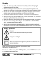
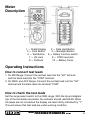
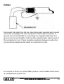
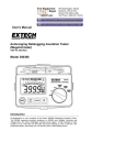
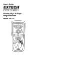
Model ST-5500
Digital Insulation Tester
Instruction
Manual
www
reedinstruments
com
Table of Contents
Safety............................................................................................. 3
Specifications..............................................................................4-5
General........................................................................................ 4
Electrical...................................................................................... 5
Meter Description........................................................................... 6
Operating Instructions.................................................................6-7
How to connect the test leads..................................................... 6
How to check the test leads......................................................... 7
Battery replacement..................................................................... 7
Measurements.............................................................................7-8
Insulation Resistance Measurements........................................... 7
Low Resistance Measurements................................................... 8
AC/DC Voltage Measurements..................................................... 8
Power Tool & Small Appliances...................................................... 9
Motors......................................................................................... 9
Cables....................................................................................... 10
For service on this or any other REED product, contact REED Instruments
at [email protected].
www
reedinstruments
com
Safety
• Read the following safety information carefully before attempting to
operate or service the meter.
• To avoid damages to the instrument do not apply the signals which
exceed the maximum limits shown in the technical specifications tables.
• Do not use the meter or test leads if they look damaged. Use extreme
caution when working around bare conductors or bus bars.
• Accidental contact with the conductor could result in electric shock.
• Use the meter only as specified in this manual; otherwise, the protection
provided by the meter may be impaired.
• Read the operating instructions before use and follow all safety Information.
• Caution when working with voltages above 60V DC or 30V AC RMS.
Such voltages pose a shock hazard.
• Before taking resistance measurements or testing acoustic continuity,
disconnect circuit from main power supply and all loads from the circuit.
Safety Symbols:
Caution
Refer to this manual before using the meter.
Dangerous voltages.
Meter is protected throughout by double insulation or reinforced insulation.
When servicing, use only specified replacement parts.
CE Comply with EN-61010-1
For service on this or any other REED product, contact REED Instruments
at [email protected].
www
reedinstruments
com
Specifications
General Specifications
Environment conditions
• Installation Categories II
• Pollution Degree 2
• Altitude up to 2000 meters
• Indoor use only
• Relatively humidity 80% max.
• Operation Ambient 0~40ºC
Maintenance & Cleaning
• Repairs or servicing not covered in this manual should only be .
performed by qualified personnel.
• Periodically wipe the case with a dry cloth. Do not use abrasives or
solvents on this instruments.
Display: Measurement Range: Sampling Rate:
Zero Adjustment: Over Range Indicator: Low Battery Indication: Operating Temperature: Storage Temperature: Power source: Dimensions: Weight:
Contents: Large LCD with dual display
200Ω, 200kΩ, 200MΩ/250V, 200MΩ/500V,.
2000MΩ/1000V, 750V/ACV, 1000V/DCV.
2.5 times per second.
Automatic adjustment.
Number 1 of highest digit is displayed.
The
is displayed when the battery voltage .
drops below the operating voltage.
0ºC to 40ºC (32ºF to 104ºF) .
and Humidity below 80% RH
-10ºC to 60ºC (14ºF to 140ºF) .
and Humidity below 70% RH
DC 9V (6 x 1.5V Size “AA” battery or equivalent)
200(L) x 92(W) x 50(H) mm
Approx 700g including the batteries
Test leads, 6 batteries, .
carrying case and manual
www
reedinstruments
com
Electrical Specifications
Accuracies are specified by:
±(…% of reading +…digits) at 23ºC±5ºC,below 80% RH.
OHMS
Range
200Ω
200kΩ
Range
Resolution
0.1Ω
+(1%+2)
0.1kΩ
Continuity Beeper
Resolution
•)))
0.1Ω
Short circuit current:
Range
1000V
Resolution
Max. open
Overload
Circuit Voltage Protection
4.5V
250Vrms
3.0V
Operation
Max.open
Overload
Resistance
Circuit Voltage Protection
Resistance≤40Ω
4.5V
250Vrms
≤200mA
DC Voltage
Accuracy
1V
+(0.8%+3)
AC Voltage (40Hz~400Hz)
Range
Resolution
750V
1V
Range
200MΩ/250V
200MΩ/500V
0~1000MΩ/1000V
1000~2000MΩ /1000V
Range
200MΩ/250V
200MΩ/500V
0~1000MΩ/1000V
1000~2000MΩ /1000V
Accuracy
Accuracy
+(1.2%+10)
Meg OHMS
Resolution
Accuracy
0.1MΩ
0.1MΩ
+(3%+5)
1MΩ
+(5%+5)
Test Current
250KΩ(load)
500KΩ(load)
1mA
1MΩ
www
Input
Impedance
10MΩ
Overload
Protection
1000Vrms
Input
Impedance
10MΩ
Overload
Protection
750Vrms
Terminal Voltage
250V+10%~-0%
500V+10%~-0%
1000V+10%~-0%
Short circuit current
reedinstruments
≤1mA
com
Meter
Description
1 — Digital Display
2 — Data Hold Button
3 — Lock Button
4 — Backlight Button
5 — Test Button 6 — Rotary Function switch
7 — VΩ Jack
8 — COM input jack
9 — Pothook
10 — Battery Cover
Operating Instructions
How to connect test leads
1. On MΩ Range: Connect the red test lead into the “VΩ” terminal .
and the black lead into the “COM” terminal.
2. On 200Ω and ACV Range: Connect the red test lead into the “VΩ”
terminal and the black lead into terminal “COM”
How to check the test leads
Set the range select switch to the 200Ω range. With the tip and alligator
clip of the test leads connected, the indicator should read 00.0Ω. When
the leads are not connected the display will read infinity indicated by “1”.
This will ensure that test lead are under working condition.
www
reedinstruments
com
Battery Replacement
1. When the battery power is not sufficient the LCD will display
.
2.Replacement of 6 new batteries, type 1.5V size “AA” is required.
3. Once replaced be sure to reinstall the battery cover and the four .
screws before operating.
Measurements
Insulation Resistance Measurements
Measurements at 200MΩ/250V
This is the voltage used for the majority of insulation resistance tests on
normal installation requirements. To measure insulation resistance, press
the test button to turn on the tester.
The LCD will display the insulation resistance. Section VII indicated that
subdivision of large installations might be necessary because of the large
number of parallel insulation resistance. In such a case, an installation
may be divided into sections, each being separately tested. Each section
must have at least fifty outlets, an outlet being a switch, socket, lighting
point etc. A switched socket counts as one outlet. The minimum acceptable insulation resistance is 1MΩ.
For a large installation, the capacitance of the insulation will be high, and
it will take longer for it to become charged by the direct testing voltage.
Be careful not to take a reading until there is a steady reading, indicating
that the charging process is complete.
Note: The charge stored in the insulation will be discharged automatically
when the test button is released. Be careful not to turn the range switch
knob while the test button is pressed, or the instrument will be damaged.
Measurements at 2000MΩ/1000V
Some specifications require testing at 1000V. This voltage must also be
selected where the supply voltage of the installation is between 500V and
1000V. First, set the range switch to 1000V and then proceed as indicated
in above for 500V testing.
continued ...
www
reedinstruments
com
The above note also applies to testing at 1000V. In addition the following
applies.
Note: Make sure that the circuit under does not include components
Which will be damaged by the 1000V applied. Many normal components
of an installation are likely to be damaged if tested at 1000V. Examples are
power factor correction capacitors, low voltage mineral insulated cables,
electronic light dimmers, electronic ballasts and starters for fluorescent
lamps etc…
Lock Power on Feature
For hands free operation a lock power on feature is incorporated in the
press to test button. Set the LOCK button to lock test voltage, pressing it
again will turn the tester off.
Low Resistance (Continuity) Measurements
1. Set the range switch to 200Ω •))) Position
2. Connect the red test lead to the V Ω terminal and back to the .
COM terminal.
3. Connect the tips of the test leads to both ends of the circuit under test.
Read resistance in Ω on the LCD.
4. When the impedance on circuit is below approximately 40Ω..
It will indicate by a continuous beeper.
AC/DC Voltage Measurements
1. Set the range switch to ACV or DCV position
2. Connect red test lead to “V Ω” terminal and black test lead .
to terminal “COM”.
3. Connect test prods of test leads IN PARALLEL to the circuit .
being measured.
4. Read the voltage value on LCD.
www
reedinstruments
com
Power Tools & Small Appliances
This test would also apply to
other similar equipment that
has a line cord. For double
insulated power tools, the
megohmmeter lead shown
(See graphic on page 8)
connected to the housing
would be connected to
some metal part of the tool
(ie: chuck, blade). Note:The
switch of the device must
be in the “ON” position and
the main power should be
disconnected.
Motors
AC-Disconnect the motor from the line by disconnecting the wires at the
motor terminals or by opening the main switch. If the main switch is used
and the motor also has a starter then the starter must be held, by some
means, in the “ON” position. In the latter case, the measured resistance
will include the resistance of the motor, wire and all other components between the motor and the main switch. If a weakness is in dicated, the motor and other components should be checked individually. If the motor is
disconnected at the motor terminals, connect one megohmmeter lead to
the grounded motor housing and the other lead to One of the motor leads.
DC-Disconnect the motor from the line. To test the brush rigging,field
coils and armature connect one megohmmeter lead to the grounded
motor housing and the other lead to the brush on the commutator. If the
resistance measurement indicates a weakness,raise the brushes off the
commutator and separately test the armature, field coils and brush rigging
by connecting one megohmmeter lead to each of them individually, leaving the other connected to the grounded motor housing. The above also
applies to DC Gemerators.
www
reedinstruments
com
Cables
Disconnect the cable from the line. Also disconnect opposite end to avoid
errors due to leakage from other equipment. Check each conductor to
ground and /or lead sheath by connecting one megohmmeter lead to a
ground and /or lead sheather and the other megohmmeter lead to each of
the conductors in turn. Check insulation resistance between conductors
by connecting megohmmeter leads to conductors in pairs.
For service on this or any other REED product, contact REED Instruments
at [email protected].
www
reedinstruments
com
10