1
Handheld Fluorometer and Turbidimeter
User's Manual
Dated: 3/08/0 I
Version . 1.1
PIN 998·0851
TURNER OESIGNS
815 W MadIA-.. . Si.rny4IIt. CA 9Ql5
IQ} 148-01194 • FAX (4OlI) 1G01118
--~ · "b"1.an...l16..f1()t!l
Table of Contents
I.
Introduction
1.1 Descri ption ........................................ .. ....... 4
1.2 Inspection and Setup ..... ..... .. .. .......... .......... 4
I.J Ge nernll nfomlation and Precautions .......... 5
2.
Quick View Diragrrams ....................................... 6
J.
Instrument Pnr.:unete rs
3. 1 Fiml\vare Aowchan .......... ..... ...... ................ S
32 Instrument Power Up ........ ..... .... .. .... .......... 10
33 Auorescence or Turbidity Channel ........... 10
3.4 Calibration Standard Value ... ....... ......... .. ... 10
3.5 Calibration ................................. ...... ....... ... 10
.l6 Sample Analysis ........... ... ... .. ...... ........ ..... .. I I
3.7 Imemal Data Logging (IDL) ......... ............. 11
3.7. 1
Activate Data Logging ................ 12
3.7.2
Download Data ............ ..... .......... 12
3.7.3
Erase Data ................................... 12
3.8 Diagnostic Info mlation .............................. 12
4.
General Considerntions fo r Analysis
4.1 Handling Samples ......................................
4.2 Linear Range and Quenchi ng ....................
43 TemperalUre Consideratio ns ......................
4.4 Positioning Samples ..................................
45 Data Qual ity .................... ..... .......... .. .. ...... ..
5.
IJ
IJ
15
15
15
Warranty
5. 1 Tenns .... ... ........................ .... ............. ........ 16
52 Warranty Service ................... ............. ....... 17
53 Out of Wammy Service ............................ 18
Aqll(ffl uorn ! User 's Manual
2
I. Inll-oduction
Appendices:
A.
Instrument SI)e<!ilicotions
A I. General Specific:uions .................. .. ... .. ..... 19
A1. Optical and Application Specifications ..... 19
D.
Interna l 0010 Logging
B I. Shippi ng Checklist ................................ .... :D
B:!. Hard ware Requirements ............................. J)
BJ. Install:lIion ......... ... .... .. ......... .. .... .. .. ... ... ...... ])
B-'. Connecting ...... .... ....... ......... ......... .... ......... J)
B5. Real Time DaHl Transfer ..... ........................ 21
B6. IDL Troubleshooting ............................ ..... :!?:
1.1 Description
TheAqllofluorn.! is a dual-channel mini flu orome ter
designed for quick. easy and aecum!e nu o rc sce~ce
and turbidity measurements. When properly cahbmted
with a standard of known concentration. the
Aqllofluorn.! di splays the actual concentmtion of the
compound.
1.2 Inspection and Setup
1.2.1 Inspection
Upon receiving your instrumem. please inspect.
everything carefull y and make sure all accessoncs arc
present. All shipments include:
C. III \ 'iI'oChlorop hyll ......................................... 23
•
•
•
•
•
The Aqllofluor™
The User's Manual
4 AAA batteries
4 Polystyrene cuvettes
Storage Pouch
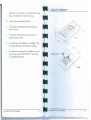
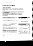
1.2.2 Setup
Before the Aqlloflu orn.! can be used. the supplied
batteries must be installed.
1.
On the backside of the instrument. loosen the SCTC\\
and re move the baltery panel (see Section 2 for
diagrrun).
2
3.
Aq//(/flu orT\! User's /l. laflual
3
Install the 4 AAA batteries into the appro priate spaces.
Replace the ballery pane l and tighten the scre w. 11le
panel has an o-ring, which creates a w atertight seal.
The battery panel may be difficult to install if there is no
AqllafluorT).! User's Manual
2. Quick View Dingmllls
lubricatiOn on the ooring . Use a silicon based o- ring
grease to lubric:llc the o-ring i r necess;lry.
13 Gcncr.tllnfonnation and Precautions
•
•
The sample compartmc nt cannot acccpt glass or
qualll cu\ ctles.
1
1.42
I
A minimum \'olume of 21111s in a lOx 10 cuvette is
requircd for best results.
"-
7.32
3.54
•
Moid havi ng any :lir bubbles in YOU1' sample. The}
c:m significantly affect the n uoresccnt rcading.
•
For beSt results measuring low turbidities. use good
polystyrene cuvcllCS (PIN 7000-957). See Section
~A for further infomm tiOI1.
Aqllonuol'nl User's Manual
5
Battery panel --"~
Aquonuor™ User's Manual
6
3. Ins trument Parameters
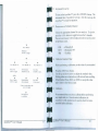
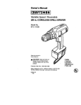
3.1 Finnware Flowchan
To,I" D..il"'
TO HU IB nloo
\ ucood ..... Ip
'-
~)
,
l .d"ml.~I(~(~'ao.'
nK""
\\\ \
II>
IDl
II,' •• S«...
•
•
•
Aguafluor
eee
P,fl\< R[ \ lh
P, ... <Alb 10 '&U"
b tl . . . .
@eG
@08
eeel
,
XXX \
,
xxx x
( . lib
<UIT> 10
...
j
A
- n'
.e,l,
xxx
,
II.E~DIVC;
•
II", IT \XX X
,
,
\\\ \
,
IO\fl' C.I So ••
lb •• p.. <ENT>
lIudio,
PffU
I~"
Sol.
( . Iib.." ...
C,,!",-pt<tld ~ENT_~
If < E ~ T> 10 101 p... "d
.il ~i.
S l.cno4,.
,b ..., ,, .. _lit ' pp'"
7
,
,
IIndl'l BL.. L
xx X
xxx X
<U P/DOWN >
A
,
,
C. I \,.1
"U,
,
P, .....$ TD \' .\ b
Aqllll nuor™ User 's Manual
, •• J •• ,
L.J".lO • .ell' n~ of
<OIl
'~~~ II
,03="'''''''_
fl.~r"<"K'
...
.\
AqulIOuorTloI Use( s Manual
< D I "'G ~
d I\ T > 10
lou" btl....
LOll'.' '01111
I.,tl \\'1:
...
~f5·8IL
'\ \X
«n·no \\ xx
8
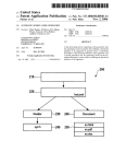
Instrument Power Up
To tum on the Alflwrluor™, press the <ON/OFF> button, The
instrument takes 5 seconds to wann up, After the \\ anll up, the
Aqllarluorn., is ready for oper-llion.
Fluorescence or Turbidi lYCh:lI1l1c l
Choose the appropri ate channel for }our analysis. To do this.
press the <AlB> button to toggle between the 2 channels,
The activated channel will be displayed in the lower left comer
of the Home screen.
•
OlL
RIVT
Pit .. <DAT A ~
D'''!OIl ''
<D AT A~
,0 '°111,
•
•
Calibrntion Standard Value
P.,,, <0 \ T '\ ~
$, ... ,_ S' op
<ENh '0 'oUZo
lRB
~.~
0 ...1014 dll.
H<ENh ,oll 'r!
•
Before performing a calibration. set the value of your standard.
P"". D I TA >lX
[ .... Dill
Press the <STO VAL> bulton.
Use the up and down arrows to adjust the standard valu\!.
Holding either arrow button down wi ll acti vate faster scroll ing.
When fi nished. Press <ESC> or <ENT> to accept the \'aluc
and 10 relurn to the Home screen,
j;\' <ENh 10 <11 11
~ EST ~
•
Su ,••. LoU'"1
d,llh ,. ,onl0
•
0 • .-.10 •• dll .
Ali do . . I.. ~ 0 4
1I1~<I<
11"0 dm
1< •• , • •
•
E.... D."
All 4.. 1 ... .. d
IOIl' ~' I~ "
111."..,
Calibration
•
Werecommcnd thai you always calibrnlc before perfonn ing
any sample analysis. A rter Ihe initial calibrat ion. Ihe
Aqllarluor"s solid standard can be used \0 check for instru ment drift and recalibration.
DII. IoU" h •
•• • 1id ~""
Aqlla rluorn 1 User's Manual
=Chlorophyll
= Rhodaminc \VT
= Turbidity
9
I.
2.
3.
·t
5.
Pre!;S Ihe <CA L> bUllon.
Press <ENT> 10 slanlhc calibr:nio n.
InStil yo ur blank and press <ENT>. TheA qllaOuorTht will
alerage Ihe nuoresccnce for 10 seconds.
Insen Ihe calibr:nion sl<lnd<lrd and press <ENT>.
Prc.ss <~NT> when the cal ibr:nion is complclc 10 accept the
c~ lt bralton. I ~ <ENT> is not pressed wi thin 10 seconds. you
WII] be asked If you MIlItIO abon the calibration. Press the
up or down aITOII to abon or accepllhc calibr.lIion respec_
tin!'!y.
If at all}time during sleps I ·~ you walll to Stop the calibration. press <ESC>. This \Ii ll return you to the Home screen
and will default the instnunent 10 the prcl'ious calibration.
I.
2.
3.
I.
2.
3.
4.
5.
3.7. 1 Acth'31e Data Logging
Press the: <DATA> builon 2 limes.
Press <ENT> to toggle between logging and stop Statuses.
Press <ESC> when l'inished 10 return iO \he Home screen.
3.7.2 Download Data
Connect tht! AqltllnuorTh1 lo the serial pon of )"our computer.
Open the Turner I:>c:s ign!> Interface Sofl ware:. See Appendix
B for computer requirements and installation.
Press the <DATA> button 3 limes.
Press <ENT> 5 times to !>Imt l~ dala dow nload.
Press <ESC> when fini shed to return to the Horne screen.
3.7.3 Erase Data
3.6 Sample An31ysis
l.
2
1
I.
2.
3.8 Diagnostic Information
3.
-t
Insert your sample.
Pressei thcr < RE AD> btllton. The instrument wi ll
autor:lIlge, then measure and average the flu orescence
signal ol'er a 5-sccond illlervaJ.
The result wi ll be di splayed at the top and center of the
Home screen.
The tOp lef! comer will display "WA IT' for 5 seconds.
Once "WA lr' disappears. another sample reading can be
perfonnt.-d.
3.7 Intemal Data Logging (lOL l
This is an op(io nal fC3lure. Iflhis feature has been purchased. your Aqllanuornt can log up to I <XX> dala points.
The .DATA screens control logging. dO\\ llloadi ng and
er:lSlIIg the d3la. For further infonnatlon. see Appendix B.
Al/lla nUOl·™ Uscr's Manual
"
I.
2
3.
4.
PreS!; the <DATA> bUllon 4 timeS.
Press <ENT> 5 times to erase lIlllogged dala.
Press <ESC> when fini shed to re tul1lto Ihe HOllie screen.
Press <DlAG> to access the diag nostic screens.
The first screen shows lhe number of dam points availab le
for internal data logging.
Press <ENT> to toggle tOlhe % FS (Full Scale) values from
the clllibration blank and slandlrd.
Press <ESC> when finished 10 re turn 10 the Home screen.
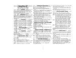
4. Ceneral Considerations for
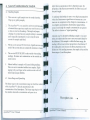
upper limit (concemnttioll) thm is dependent upon: the
propenies o f the nuorescent mmerial. the filte rs used. and
the path length.
L
A nonlinear relrllionship is seen at very high conce ntratio ns
where the fluo rescence s ignal does 110( increase at a constant Nne in comparison to the ch:lI1ge in concentratio n. At
e\'en higherconcenu-ations. nuo rescence s ignal will dec rease e\'en tho ugh the sample concentrntiOllS are greater.
This effect is known as "signal quenching".
T:\h.c cafe not 10 spill samples 111\0 the sample chamber.
Wipe up any spills promptly.
2.
The Aqllllnuornt is "cry sensiti ve ilnd e\en s mall rU1l0unts
of m:lIcrial from :I pre\ iOliS s.1mple 1I13Yresuh in errors. Use
a clean eU\ene for all readings. Thorough and proper
cleaning o f cu"cnes between sample readings is essential.
Linearity may be c hecked by diluting a sample I : I o r some
otherconveniem r3lio (be s ure to use your matri x blank for
the di lutions). If the s..1 mple is within the linear range. the
reading will decrease in direct proponion to the dilution. If
the reading does not dec rease in direct proponio n to the
dilulion or if the rending increases. the sample is beyond the
linear range of your fluorophore .
and is especially important if you an.: using the same
cuvctte for samples and bl:lllk.
3.
Fililhe ell \ cite alieaSI501'f full (1m ls). Significant clTOr can
result if the cuvelle does not contain this minimulll volume.
...
The cuvelle 1\1UST BE DRY on the o uts ide when taking
readings. ~Io i s tll re and condensmion o n the o uts ide cnn
result in error.
5.
Minute bubbles in samples will cause drifting readings.
Take care nOI to Introduce bubbles into s:tlllpies. Slight
tapping with }our finger on the o uts ide c uve ue wall will
often help dissipate bubbles.
III
"uc
"~
~
·t?: Linear Range a.nd Quenching
o
=>
The linenr range is the concentration range in \1 hich the rendout
of the Aql/(/fiuorThI is directly Ilropo niona.lto the
cOl1centrmion of the flu orollho re. The lincar ran ge bcgllls with
the smallest dctectable concentratio n and spans to all
u:
F1uorophore cone.
Aqll(lfluor™
U~ r 's ~Iallual
Aqllafluor™ User's Manual
13
14
4..3 Tcmpcrnturc Consid.:rntions
Auoresccnce IS te mpernturc sensitive. As the tempcrnture of
t
accuracy. read blan k. standard . and s.1mples allhe same
lempcl':tturc.
the sample IIlcreascs. the fluo rescence decreases. For
~.4 Pm.itio nin g Samples
For 10\ \ concent ration samples. cuve ues o ften will <Ji ve
slightly d ifferenlmeasurcmcllIs depending upon I~ir
~nc nt a ti on in Ihe sample compart me nt. This is due 10 defects
In the shape of the cu\ ette Ihm are nOI \ isible to the human
eye. We recommend that the cuVelic be marked :u tile
POs i t i ~lI:d in the 5.1l11ple compart ment lhe same way each
10 11IIIIIIIlIZe error.
We ha \e found thm tu rbidity is particularl y sensitive to thIs
faCIOI'. We recommend for beSt results. using high quality
pol ys tyre ne cuvetles (PIN 7000-957 1 which showed little
orient ation and cuveue 10 cuvc uc v:m auoll in testina0 '
~.5
Data Qualily
The AqulI nuorn l is o nly as accurate as the standards Ihat are
used tocahbrate it. Thi s is why it is impon:lIlt 10 take care
when pre paring stand:lrds. sam ples. and bl ank. One should
follo\\ good laboratory practices .... hen pfepming al l solulions
and rC:lgent:;.
Tumer Designs watT:lI1lS the Aqllufluorn1 Fluoro1lleter and
accessories to be free from de fects in materials and wOI'kmanship under nomlal use and service for a period of one year
from the time of imti(ll pUl'ch:lse. with the following res tl'ictions:
I. The instrument and acces$Ories mU SI be instalk d. po\\ crcd.
and operatcd in compliance wilh Ihe directions in this
dQllafluor tM U$« ( s Manual and di rections accompanyi ng
the nccessories.
2. Damage incurred in shipping is ll2l co\'ered.
3, Damage resulting from mcas uremcnt of samples found to be
incompatible with the rnatcri:l ls used in thc sample system is
ll21 co\'cred.
4, Damage resulting fro m cont act with corrosi"e matcrialsor
at mosphere is lliI.l covered.
5. Damage from se.1Wate r and olher moder.llc ly cOlTOsh'c
materials that are not promptly removed from the instrume nt
are I!2l cove red.
6. Damnge cnused by modifi cation or the instrument by the
customer is ll21 covcred.
"
5.:! \\':ur.mIYSerdCI!
To oblalll sen ice during the \\1an':l llt} period. the owner
sh:llltal..e the fo llo\\ ing steps:
I. Write or call the Turner Designs sen ice depanment and
de~c nbe as precisely :IS possib le the n:lture of the
problem.
2 Carry out minor adjustments or tests :u. suggested b} the
Scn icc Depanment.
J If proper perfonn:1nce is not obtained. ship the instrument. prepaid. to Turner Designs. \\ilh a statement of
shippmg chat-ges. The instrument will be repaired and
n!turned free of charge. along with a check to co\cr
shippmg charges. for all customers in Ihe contiguous
continental United States.
5.3 Ollt-of-Warranty SeJ"\'ice
Proceed e'(actly as for Warmnty Sen ice. above. If our
service depanmellt can assisl you b) phone or cOlTespondence. we wi ll be g lad 10. al no charge.
Rep3irservice wi ll be billed on a basis of time and maleri31s. A complele statement or time spent and materi:lls used
will be supplied. Shipment to Tumer Designs should be
prepaid. Your bill witl include retum shipment freight
charges.
Address rorShipment:
Turner Designs
8"-5 W. !\laude A\e.
Sunnyvale. CA <).U)85
For customers oUlside of Ihe contiguous continental United
States. and \\ ho ha\e purchased our equipment from one of
our authorized d istribulOB. contact the disu'ibutor. If you
have purchased di rect. contact us. We will repair the
instnunent al no charge. but we wi ll not pay for shipment.
documentation. etc. These charges \\ ill be bitted at cost.
NQ.IEl Under DO conditions should the instrument or
accessories be retll l1led withouillotice. Prior correspondence is needed:
a.
To ensure that the problem is not a tri vial one. easily
handled in your laboratory. with consequent S:I\ ings to
e\eryone.
b.
To specifically detemline the nature of the problem.
so that repair can be rapid. with panicul:lr allenlion
paid 10 the defect you have nOh!u.
Al/llofluorT\t User's Manual
Aqllonuor™ User's M3nual
17
IS
f\
III
lI~lI'Umt:1lI ",peC III C~lll O llS
IJIX=II UIA ...,.:
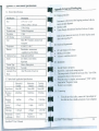
A I. Gencrnl Specifications
Apl)endix B: Inlermll Datalogging
B I. Shipping Checklist
SD«ilictllion
Descri lion
I.7s".'( 3.5".'( 7.25"
Siu
Instmments with intcmal datn logging purchased will also
recei\'e in their shipment:
Interfacecable
Tumer Designs Spreadsheet Interface Software (2 disks)
(~ A5c01'\8 .9cmx
18.-k01I
13.90z (OAkg)
3 orders of magnilu<k
12 bIts
2 .'( 16ch:lr.lCters
Meets IP 67 Standard: dustproof:md
\\ aterproof
~1-1~ ·F: S...JOOC
Pholodiodes: me3Suremelll
cap3bility from300-IOOOnm
Single-pai m and blanl
1.0\\ b::mery. circuit railure.
High blank
IOmm'( IOmm pl3Stic
5 seconds
After 90 seconds of inacti\ il~
Wdght
Dynamic r:mge
Resolution
LCD Display
c,'"
Temper:nun!
I)cteclOr
Calibration T) I)I!
AI:ums
Cuvelle Typt
Warm Up Time
Automatic Po\\er
Donn
•
•
Both of these items are necessary for reuie\ing the stored
dal3 in the Aqllafluo rnl .
B2. Hardware Requirements
•
•
•
B3. Installation
I.
2
3.
A1. Optical and Applic:lIion Specifications
Rhodamine
Ch:umel
Green LED
Turbidity
Channel
Green LED
E.~cit:lliQn
o li c~
-160: "Olllll
5-Uh-20nrn
S lhlOnm
Emission
Oplies
>66Sn01
>S7Onm
SIS:IOnm
Lnllil of
Dch..'C'lion
Max range
O.15ug/l
OAppb
O.SNTU
> 800 ppb
>.IDOppb
Temper:nurc
coefficients
IA'd e
Liuear
Llgln SOllrce
5.
Exit a11 Windows programs.
Insert Disk I and mn the setup program.
TIle setup wizard will install the necessary filt:s. YOLl will be
prompted for Disk 2 when necess.'lry.
When the setu p is complete. an icon named "_TO:?.... will be
found in the "'Programs'" menu .
Restart your computer.
B~ .
Connecting
4.
Chlorophyll
Channel
Blue LED
PC with Windows 95 or Intcr
MS Excel5.00rlater
At least I available serial pel1
I.
Aqllilfl uo rnl Uscr"s
~ I a ntla l
O.U:!6/"C
Expu ncllIml
Using the pro\'ided cable. connect the 9 pi n adapter o f
the cable into the :l\'ailab le serial pen of your computer.
>150 NTU
NIA
19
Aqllofluor™ User's r.·lanual
'0
I.
Plug the opposite cnd or the: cable ima the base of
the AlfllafluorTM,
2.
3.
4.
5.
6.
B.6 IDL Troubleshooting
Open MS Excel 5.0 or later.
Open the TD?: spreadshc<!t imetface software.
Click oillhe 00:< [0 [he righ t o f the CO"" 1)011 icon [0
select Ihe app.-oprionc CO!\ I poll. Thi s is usually
__
.,..
CO!\ I POlt 2.
CUd. on "$t,II"', The progrnm will open:1II E~cc l
spre:'ldshcct for daw transfer. The boxes left o f the
COM pon and 1\'15 Excel should bOlh be green.
Follow the directions from Section 3.7 forco lkcting
and downloading dala from the Aqlllln uorT~I. Dala
\... il1 automatical ly :tppearil1lhe excel spreadsheet.
BE SURE [ 0 save this dal3 BEFORE closing the TD
soft ware.
85. Real Time D:lIa Trnosfcr
Data can :llso be Ir:tnsfcrrcd din.'Clty [0 the computer after
t:!:lch reading. To do so:
I.
2
3.
Slopdma logging (see 3.7. 1)
Follow SICpS 1·6 of 84 \0 crate the connection
between lhe Aqu(lnuornl and you r computer.
Inse rt a sample and press the <READ> bUllon. The
results wil l automatically tr.\nsfer to the acti\'c Excel
spreadsheet.
Aqllanuor™ User's Manual
21
..
Diffic ulties C:1Il arise when p:U1ltlletcrs arc sct incolTecl ly o.
connections with t ~ cable are not tight enough. Here are
some common problems.
I.
Box to the left of the COM pon is red. This means Ihallhe
CO)'.'. port is nOlavai lable. Causes:
a. Another instrument or program (such as palm
pilotl hot sync) could be occupying the pon.
making it una vailable. t-.hJ..e sure to close a\l
programs of this type before downloading da ta
b. The pol1 selected is inco rrect. Follow step ~ of
connecting to choose anClller COJ\I pon.
2.
All lights are green. but no data transfen-ed. e\e n though
the instrument says "A ll data downloaded".
a. The connection between the instrument and the
computer is bad. Check and tighten the cable
connections. Make sure both ends o f the cable
are plugged in tightly.
Appendix C : I" Vil'O Chlorophyll
The detection of ill I'il'O chlorophyll a is by Ilmurc. a
qualitati\e measurement. Physiological . en\ ironmental.
morphological. and temporal factors att cOntribute to the
variation between the il/ dl'o signal and the actual chlorophyll (1 co nc~rurati o n of a sample. Physiologic:'!1 effects stem
from th..:: change in nuorescence per unit chlorophyll o f ce lls
at varying physiological states. O n a basic le\el.:'!n 'unhealthy' cell will nuoresce more thM a 'healthy . cell due to
the li ght energy nbso rbed is channeled into photosynthesis.
Ho\~ever. in nmural asSt!mblages of phytoplanklon. there is
nomlarty a mix of species at val) ing degrees of health. thus
averaging oUilhe physiologic!!! effecl.
be susceptible to more interference than filte rs wuh a narrower
bandpass.
In spite of Ihese concerns. this d~s not mean that actual .
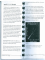
chlorophyll concenlr:ltions c:\lmOI ~ e~tra~laled frolllthe /1/
1'i1'0 daw. A simple way o f con'c!aung III 1'/1'0 data, to ~c t ual
chlorophyll concentr:ltions is accompli shed by ~nodl ca ll y
collecting "grob" samples for chlorophyll extraction, Sc\'eral
samples should be collected \\ ithin each niche or cn\ ironment.
AI me time of collection. the inl'iI'O value must be noted. Once
the chlorophyll concentration has been detcnnined ~hrough
extr:lction. the concentration should be correlated Wllh Ihe
corresponding ill 1';1'0 value (see Graph C IJ
Environmental effeclsderi\e fro m mainly IWO factors: light
and temperalure. The light history of an algal populmion wi ll
affect nuorescence of li ving cells. Cells in a darker environment will nuoresce more perunil chlorophyll than cells in a
\'-ell lit zone o f the wmercolumn. One way of reducing the
eff~cts of light is 10 ··darl.. adapt"· your sample before
analyzing it. T~mpernlure effects :1rC discussed in section
4.3 o f Ihe manual. For beSt sample analysis. all samples and
calibration solutions should be measured at the same
temperature.
TempomllSpatial effects are mainly due to differences in
quantum efficiency :lnd cell size between different species of
phytoplanktOll and photosynthetic bacteria.
Interfering compounds in natural watel"$ deli\c from sc\ernl
sources. The mo:.t common interfering compounds include
pheophYlins. chlorophyll band c. dissolved organic matter
and nuorometer. Optical filters \\ ith a wider bandpass will
Aql/{l nuor nr User's I\lanual
GrnphC I
For detailed information on chlorophyll anatys is. pka5e ~ ehe
reference list below or visi t the Turner Designs \\Cbp3ge m
w .... y. OuolJlmeter cQm
Aqllonuor™ User's Manual
24