1
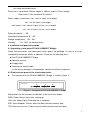
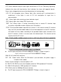
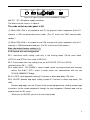
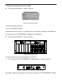
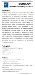
USER
MANUAL
FE1&10/100BASE-T Bridge
Contents
1. Product description ...................................................................................................................... 2
2. Main features ................................................................................................................................ 2
3. Technical specifications............................................................................................................... 3
4. Installation and panel description............................................................................................... 4
4.1 Unpacking(stand alone FE1&10/100BASE-T bridge)........................................................... 4
4.2 Front and rear panel of the stand alone device..................................................................... 4
Figure 2 front panel of FE1&10/100BASE-T bridge.................................................................. 4
4.3 Front and rear panel of the rack mount .................................................................................. 7
5. Applications of FE1&10/100Base-T bridge............................................................................... 8
5.1 Definition of balanced twisted-pair wire sequence for RJ45 interface ............................... 8
5.1.1 10/100BASE-T interface wire sequence ............................................................................. 8
5.1.2 E1 interface wire sequence................................................................................................... 8
5.2 Setting of DIP switch and jumper............................................................................................. 9
5.2.1 Setting of E1 interface impedance ....................................................................................... 9
5.2.2 System test and configuration .............................................................................................. 6
5.3 Configuration of Ethernet connecting devices ....................................................................... 9
5.4 Simple self-test methods for devices and E1 circuits ......................................................... 10
5.5 Typical applications.................................................................................................................. 10
5.6 Common questions and their maintenance ..........................................................................11
1
1. Product description
FE1&10/100BASE-T Interface Converter (also as FE1&10/100BASE-T Ethernet
Bridge) is an Ethernet bridge of high performance, which accomplishes the converting
between the 100M Ethernet port and the E1 port. As an extended device of the Ethernet,
the FE1&10/100BASE-T bridge realizes interconnection of two Ethernet by using the E1
channel provided by existing networks with low cost.
10/100Base-T (RJ45) interfaces are provided at the end of Ethernet LAN to
accomplish various functions including MAC address self-learning, address filtering,
address table maintenance and flow control.
E1 interfaces conforming to ITU-T G.703 and G.704 proposals are provided at the end
of WAN, supporting RJ45 and BNC connection modes. The E1 ports support both framing
and un-framing architecture. The user can select an operating mode for the E1 interface
according to the connected E1 environment. This provides flexibility of network application.
In the framing mode, the E1 interface provides a rate of N*64Kbps N=1~31 . In the
un-framing mode, the E1 channel provides a rate of 2.048Mbps and accomplishes
transparent transmission.
If the FE1&10/100BASE-T bridge is used in the framing mode, the transmission clock
can be either provided internally, i.e. using the main clocking timing mode (INT), or
extracted from the E1 channel, i.e. using slave clock timing mode.
The FE1&10/100BASE-T bridge provides plenty of self-test functions, supporting local
loop and remote loop. It also provides pseudo random code test function to test error
codes in the circuit.
It is proposed to use the products of this series in pairs.
A typical application is shown in figure 1.
FE1/ETH
ETH
POW ER
LNK
SWI TCH/ HUB
RX
E1
TX
LOF
LOS
A
TEST
AS
CRC
LO OP
PTOK
SDH
FE1/ETH
ETH
PO WER
LNK
RX
E1
TX
LOF
LOS
TEST
AS
CR C
LO OP
PTO K
B
SWI TCH/ HUB
Figure1 typical application of FE1&10/100BASE-T bridge
2. Main features
In accordance with the provisions of IEEE 802.3 802.3u Ethernet, ITU-T G.703, G.704
and G.823 protocols.
E1 interface framing/un-framing optional; balanced 120ohm unbalanced 75ohm
optional.
The E1 interface uses PCM31 mode, supporting CRC check.
E1 interface main/ slave clock optional in the framing mode.
2
In the E1 framing mode, the number of time slots is optional from 1 to 31.
Supporting 2.048Mbps transparent transmission in the E1 un-framing mode.
The 10/100BASE-T Ethernet interface supports 10/100M half/ full duplex modes.
MAC addresses self-learning and addresses filtering functions, reducing the
transmission load of the E1 circuit.
Built-in 64Mbits SDRAM Ethernet data buffer memory, improving the capability of
Ethernet side anti-outburst, assuring high throughput of data transmission.
E1 circuit remote loop and local loop tests.
Pseudo random sequence test, facilitating the test of E1 circuit.
Perfect circuit test and alarm indication.
Two architectures: stand alone and 19in rack mount architecture (16 interface
converter modules can be inserted in the rack mount architecture) ;
Optional AC 220V or DC –48V input for bridge of both architectures
Hot rear up of double power supplies is provided for the Bridge of rack mount
architecture, assuring high reliability.
3. Technical specifications
Protocol: G.703, G.704, G.736, G.823, I.431
IEEE802.3 10BASE_T
IEEE802.3u 100BASE_T
Circuit interface (E1):
Impedance: 75Ω, physical interface: BNC
Impedance: 120Ω, physical interface: RJ45
interface rate: framing: N*64Kbps N=0~31; un-framing: 2.048Mbps
Coding: HDB3
Jitter tolerance in accordance with G.823
Output jitter < 0.05UI
Data interface (100BASE_T):
Impedance: 100Ω, physical interface: RJ45
Interface rate: 100Mbps
Coding: Manchester
Cable: 75Ωcoaxial-cable, UTP5 twisted pair
Transmission range: circuit interface: BNC: 600m; RJ45: 300m
Data interface: 100m
Indicator: indicating power, connection states of data and circuit interfaces, operation state,
3
test state and trouble alarm.
Dimensions: stand alone: 154mm (depth) x 190mm (width) x 37mm (height)
Rack mount: 19in standard 4.5U cabinet
Power supply: stand alone: 160V 270V AC input, 5V/2A output
-40V -60V DC input 5V/2A output
rack mount 150V 260V AC input 5V/16A 12V/1A output
-38V -58V DC input 5V/16A 12V/1A output
Power dissipation
3W
Operational temperature: 0
50
Storage temperature: -20
80
Humidity:
5% 90% (no condensation)
4. Installation and panel description
4.1 Unpacking (stand alone FE1&10/100BASE-T Bridge)
Check the accessories and spare parts when opens the package. In case of missing,
immediately contact our offices or agencies. Check for the following items:
■ One FE1&10/100BASE-T Bridge
■ Operation manual
■ A supply cord
■ Two plugs for coaxial cable
In case of any damage in transportation, contact our offices or agencies.
4.2 Front and rear panel of the stand alone device
The front panel of the FE1&10/100BASE-T Bridge is shown in figure 2.
FE1/ETH
ETH
POWER
LNK
RX
E1
TX
LOF
LOS
TEST
AIS
CRC
LOOP
PTOK
Figure 2 front panel of FE1&10/100BASE-T Bridge
Explanations for the two rows of indicators at the left are as follows:
PWR: Power. Always lights after starting up.
LNK: Link. Always lights if the data link is complete.
RXD: Data reception. Flickers when the data interface receives data.
TXD: Data transmission. Flickers when the data interface transmits data.
4
LOF: Alarm indicator lamp for input signal out-of-frame in E1 line. Constantly lightening
indicates the alarm with local device; flash indicates the alarm with opposite device.
Alarm status of opposite device can be detected only at framing mode.
LOS: E1 link interruption alarm. Always lights after starting up till synchronization is
established. It also lights in case of E1 link interruption or signal loss in
communication.
AIS: Always lights after receiving a alarm indication signal.
CRC: Always lights after finding CRC check error.
TEST: Test. Always lights in testing (transmitting local or remote E1 interface loop
instructions or pseudo-random sequence test instructions).
PTOK Circuit pseudo-random sequence test success. In the state of remote E1 interface
loop, transmits pseudo-random codes to the remote equipment via local E1 interface,
and checks for error codes according to the pseudo-random codes received at the
local E1 interface. If there is no error code, the indicator lights. This function can be
used to check the E1 circuit.
120¦¸
V1.2
E1-75 ?
TX
RX
ETH
E1-120 ?
75¦¸
RLOOP
1 2 3 4 5 6 7 8
INT-CLK
ON
L-SLOTS
ON
LLOOP
OFF
COMMON
AC
R-SLOTS
220V
LINE-CLK
Note: Circuit pseudo-random sequence test is valid only when the local equipment
is in the framing mode and main clock is configured.
The AC input rear panel of FE1&10/100BASE-T Bridge is shown in figure 3.
Figure 3 AC input rear panel of FE1&10/100BASE-T Bridge
220V AC: AC socket with two cores
OFF ON
Power switch. When the ON button is pressed down, the power supply is
turned on 8 bits coded
Switch: System configure, more description in 5.2
E1-75Ω TX RX: BNC transmission/reception socket for 75Ω impedance E1 interface
E1-120Ω: RJ45 socket for 120Ω impedance E1 interface
ETH: RJ45 socket for 100Mbps Ethernet interface
The DC input rear panel of FE1&10/100BASE-T Bridge is shown in figure 4.
5
120¦¸
V1.2
E1-75 ?
TX
RX
ETH
E1-120 ?
75¦¸
RLOOP
LLOOP
1 2 3 4 5 6 7 8
INT-CLK
ON
L-SLOTS
LINE-CLK
ON
R-SLOTS
OFF
COMMON
48V DC
Figure 4 DC input rear panel of FE1&10/100BASE-T bridge
48V DC
DC -48V power supply connector
The others are the same as in figure 3.
The code switch on rear panel is S5.
(1) When S5.6~S5.8 is all jumped to end 75, the physical match impedance of the E1
interface is 75Ω non-balanced coaxial cable. (The E1 circuit uses BNC coaxial-cable
sockets.)
(2) When S5.6~S5.8 is all jumped to end 120, the physical match impedance of the E1
interface is 120Ω balanced twisted-pair. (The E1 circuit uses RJ45 sockets.)
Note: the default factory setting is (1).
5.2.2 System test and configuration
S5.1: main/slave clock setting, valid only in the framing mode. ON for main clock
(INT-CLK) and OFF for slave clock (LINE-CLK).
S5.2: Track remote time slot setting or not, on for R-SLOTS, OFF for L-SLOTS.
(valid only when S5.1
OFF)
S5.3: mode select. ON (COMM) = select a mode switch can communicate with common
device like RJ017. OFF= select a mode switch can communicate with our old
FE1&10/100BASE-T Bridge.
S5.4: LLOOP. Local loop back setting (E1 interface in direct loop back), ON valid.
S5.5: RLOOP. Remote loop back setting (remote E1 interface in direct loop back), ON
valid.
Remote loop loops rear the E1 port of the remote equipment by sending remote loop
instructions to the remote equipment through the local equipment. Remote loop can be
used to check the E1 circuit.
When you set RLOOP, you must at main clock mode.
6
4.3 Front and rear panel of the rack mount
The front panel of RACK is shown in figure 5.
Figure 5 Front panel of RACK
+5V: 5V main power indicator
+12V: 12V fan power indicator
Underneath the panel there is an indicator matrix. See figure 2 about the description of
the front panel of FE1&10/100BASE-T Bridge for its functionality.
O
I
I
The rear panel of RACK is shown in figure 6.
O
Figure 6 Rear panel of rack
The panel above consists of three different small panels:
The small panel of FE1&10/100BASE-T bridge module, as shown in figure 7.
Figure 7 Panel of FE1&10/100BASE-T bridge module
See figure 3 about the description of AC input rear panel of FE1&10/100BASE-T bridge
7
for the functions of every component of the small panel.
O
The panel of RACK/AC AC redundant power supply is shown in figure 8.
I
Figure 8 Panel of rack/AC AC redundant power supply
160-270VAC: AC 220V input socket
ON OFF: Power converter
+5V: 5V main power indicator
+12V: 12V fan power indicator
O
The panel of RACK/DC DC redundant power supply is shown in figure 9.
I
Figure 9 Panel of rack/DC DC redundant power supply
40-60VDC: DC-48V connector (FG to protective GND, “- +” is the polarity of the –48V
DC input)
ON OFF: Power converter
+5V: 5V main power indicator
+12V: 12V fan power indicator
5. Applications of FE1&10/100Base-T Bridge
5.1 Definition of balanced twisted-pair wire sequence for RJ45 interface
5.1.1 10/100BASE-T interface wire sequence
The RJ45 Unshielded twisted-pair for 10/100BASE-T interface can use DCE or DTE
standard stipulations, it support AUTO MDI/MDX function.
5.1.2 E1 interface wire sequence
1 and 2 are transmitting lines, 4 and 5 are receiving lines, as shown in figure 17.
1. TX+ Positive end of data transm ission
2. TX- Negative end of data transm ission
1
2
3
4
5
6
7
8
3. Idel
4. RX+ Positive end of data reception
5. RX- Negative end of data reception
6. Idel
7. Idel
8. Idel
8
Figure 17 RJ45 balanced twisted-pair interface wire sequence for E1 interface
5.2 Setting of DIP switch and jumper
For a rack mount unit, the module can be easily drawn out from the guide channel just by
unscrewing the screws on the module panel.
5.2.1 Setting of E1 interface impedance
Bottom coded switch, as shown in Figure 18
E1 TS
0
7
ON
1 2 3 4 5 6
15
ON
7
8
1
ON
2 3 4 5 6
7
8
31
23
1
ON
2 3 4 5 6
7
8
1
2 3 4 5 6
7
8
Figure 18 E1 Time Slot Setting
After time slot 0 is valid, other coded switches in whatever positions are all valid. Select
the number of time slots according to the expected rate. Normally for an independent type,
a time slot setting of automatic tracking Central Site module is selected. Coded switches
of plate-clip time slot correspond to S1, S2, S3 and S4.
SW
0
16
Status
ON
OFF
ON
Function
Unframed 2048KBps
CCS (PCM31)
Status
/
OFF
OFF
Function
/
CAS (PCM30)
Default
OFF
OFF
●1st switch (S1.1) is used for controlling E1 framing/non-framing. “ON” refers to
non-framing mode (2.048Mbps).
●31 switches, from 2nd—32nd (S1.2~S1.8, S2, S3, S4), are respectively used for
controlling the selection of 1st –31st time slots. Set at “ON”, the corresponding time slot is
selected; set at “OFF”, the corresponding time slot is not selected. The rate of E1
interface is completely dependent on the number of the selected time slots.
For example: the setting of 3rd switch to “ON” and all other switches to “OFF” indicates
that 2nd time slot is selected, at this moment the rate is 64K; the setting of 7th and 8th
switches to “ON” and all other switches to “OFF” indicates that 6th and 7th time slots are
selected, with a rate of 2*64K=128K. TSO setting is used for specifying E1 frame to be
transparent or framing: ‘0’--framing, “1”--non-framing. But the bit has to be specified in
combination with other time slots. TS16 setting is used for controlling E1 frame structure
to be PCM30 CAS or PCM31 CCS : ‘0’—PCM30, at this moment 16th time slot must not
be used for transmission service; ‘1’—PCM31, 16th time slot can be used for
transmission service. Besides, TS1—TS31 are respectively used for controlling the
selection of 1st—31st time slots: ‘1’—the corresponding time slot is selected; ‘0’—the
corresponding time slot is not selected.
5.3 Configuration of Ethernet connecting devices
The equipment uses 10/100BASE-T Ethernet interfaces and supports adaptive
9
10/100M half/full duplex mode. Ethernet devices connected to FE1&10/100BASE-T bridge
(such as SWITCH, HUB, Ethernet adapter card (NIC), etc.) can be set to 10M full duplex,
10M half duplex, adaptive 10M half/full duplex and adaptive 10/100M.
Note: Ethernet devices connected to FE1&10/100BASE-T Bridge can not be set
to the enforced operating rate of 100M.
5.4 Simple self-test methods for devices and E1 circuits
Test 1: test of back-to-back connection
Connect two FE1&10/100BASE-T bridge devices back to back, ping the other’s IP
address on the two computers to test the two devices.
PC1
PC2
A
B
FE1/ETH
FE1/ETH
E TH
E TH
E1
LNK
TX
L OF
RX
E1
TE ST
TE ST
P OW E R
P OWE R
AS
CRC
L OOP
L NK
RX
TX
L OF
L OS
AS
CRC
LOOP
PT OK
PT OK
LOS
Test 2: test of E1 circuit transmission error codes.
Connect the device in the real operational environment, check the E1 circuit with the
loop and pseudo-random sequence test function provided by the device.
If the exchange end and the user end is very far away, the E1 circuits of the two
FE1&10/100BASE-T bridge must be correctly connected first. Otherwise, indicator LOS will
always light. Set the device at the exchange end to framing and main clock mode, set S5.1
(RLOOP) to ON, pseudo random sequence test will be executed. If indicator TEST and
indicator PTOK at the exchange end always light, it indicates successful loop and pseudo
random code test and the E1circuit has no error code.
S5.1
S5.5
ON
ON
A
FE1/ETH
B
ETH
POW ER
LNK
E1
TX
RX
LOF
SDH
TE ST
AS
CRC
LOOP
P TOK
LOS
FE1/ETH
ETH
POW ER
LNK
E1
TX
RX
LOF
TE ST
AS
CRC
LOOP
PTOK
L OS
5.5 Typical applications
Mode 1: connect Ethernet with E1 networks.
SDH, PDH and DDN networks have already been widely adopted. With E1 channels
provide by such networks, bridging connection and interconnection of two Ethernet
networks at different locations can be easily realized by the FE1&10/100BASE-T bridge.
FE1/ETH
E TH
POWE R
SWI TCH/ HUB
LNK
RX
T EST
E1
TX
LOF
L OS
A
AS
CRC
L OOP
P TOK
SDH
FE1/ETH
E TH
POW ER
LNK
RX
E1
TX
LOF
L OS
B
T ES T
AS
CRC
LOOP
P TOK
SWI TCH/ HUB
10
Connecting two Ethernet networks with an E1 network.
Mode 2: Extend an Ethernet network with existing twisted pair or coaxial cable.
Connected with twisted pair or 75Ω coaxial cable, the E1 ports of FE1&10/100BASE-T
Bridge support a transmission range of 300m or 600m. Two Ethernet networks at different
locations can be bridged by two FE1&10/100BASE-T bridge with existing twisted pair or
coaxial cable.
FE1/eth
FE1/eth
E TH
E TH
LNK
TX
LOF
RX
SWI TCH/ HUB
E1
TEST
TES T
E1
POWE R
POWER
AS
C RC
LOOP
LNK
RX
TX
LOF
LOS
AS
CR C
LOOP
PTOK
P TOK
LOS
A
B
SWI TCH/ HUB
-
Extending Ethernet with existing twisted pair and coaxial cable
5.6 Common questions and their maintenance
(For independent interface converter, reference for frame bridge)
No.
1
Symptoms
Causes
The power indicator
The power circuit
1. The power is not connected. Check the contact of
does not light after
has a failure.
the power lines and the converters.
starting up.
Remedies
2. The internal fuse of the equipment is broken.
Replace the fuse.
3. The internal power module has a failure. Send it
rear to factory for repair.
2
Indicator LNK does
Integrity test of link
1. The type of the cable does not meet the
not light when the
has not passed.
DTE/DCE modes of the Ethernet ports of the
Ethernet network is
equipment.
connected.
2. The crystal head of the cable is not well molded.
Check the quality of the UTP cable.
3. The rate setting of the converter or the network
card is wrong. See 5.3.
4. The internal circuit of the equipment is damaged.
Send it to factory for repair.
3
Indicator LOS always
The circuit signals
1. Check the coaxial cable or the UTP5 twisted pair
lights when the cable
are lost.
for open circuit and short circuit. Check whether the
at the E1 port is
plugs are positioned.
connected.
2. The factory default of the equipment is 75ΩBNC
interface. S5.6~S5.8 should be reconfigured if a
120ΩRJ45
interface
is
used.
See
5.2.1
for
reference.
3. The internal circuit of the equipment is damaged.
Send it to factory for repair.
11
4
Indicators
are
The
normal,
but
devices are in the
is wrong. The converter for local loop test should be
communication
can
state of local loop
set to OFF(turn up) to make it invalid.
test
2.
not be done.
opposite
and
the
1.
The setting of LLOOP of tumbler converter S5
The Ethernet link of the opposite interface
Ethernet link of the
converter has a failure. Check the opposite devices
opposite
according to item No. 2 in the table.
devices
has
no
communication.
12