1
Contents
I
Table of Contents
Part I Introduction
1
1 Supported
...................................................................................................................................
Hardware
1
Part II Configuration
3
1 Installation
................................................................................................................................... 3
2 Activation
................................................................................................................................... 4
3 Hardware
...................................................................................................................................
Configuration
6
..........................................................................................................................................................
6
Configuring NMEA0183
hardw are
..........................................................................................................................................................
13
Configuring hardw
are using plugins
4 Dredging
...................................................................................................................................
Configuration
17
..........................................................................................................................................................
17
Dredging hardw
are
..........................................................................................................................................................
18
Single segm ent cutter dredger
5 Software
...................................................................................................................................
Configuration
21
21
Echosounder..........................................................................................................................................................
Offset
..........................................................................................................................................................
23
Motion sensor calibration
..........................................................................................................................................................
25
Vessel shape and offsets
..........................................................................................................................................................
29
System Settings
6 Geodesy
...................................................................................................................................
Configuration
32
Manage
Manage
Manage
Manage
Manage
.......................................................................................................................................................... 32
Ellipsoids
34
Map ..........................................................................................................................................................
Datum s
..........................................................................................................................................................
37
Map Grids
..........................................................................................................................................................
40
Geoids
..........................................................................................................................................................
42
Countries
Part III User Interface Features
44
1 Projects
................................................................................................................................... 44
2 Toolbar
................................................................................................................................... 50
3 Accelerator
...................................................................................................................................
Keys
51
4 Data View
................................................................................................................................... 53
5 Helmsman
...................................................................................................................................
Display
57
6 Area Measurements
................................................................................................................................... 60
7 Alarms
................................................................................................................................... 62
8 Query...................................................................................................................................
objects
69
9 Coordinate
...................................................................................................................................
calculator
71
Part IV Map display / Background maps
75
1 Loading
...................................................................................................................................
Maps
75
2 Loading
...................................................................................................................................
IHO S-57 ENC's
77
3 Loading
...................................................................................................................................
IHO S-63 ENC's
78
4 Supported
...................................................................................................................................
Raster Formats
83
5 Supported
...................................................................................................................................
Vector Formats
83
(C) 2015 ActiveXperts Software B.V.
I
II
ActiveXperts Hydromagic 7.0
6 Downloading
...................................................................................................................................
Maps
84
7 Changing
...................................................................................................................................
drawing order
88
8 Adding
...................................................................................................................................
waypoints to the map
89
9 Projecting
...................................................................................................................................
Waypoints
93
10 Adding
...................................................................................................................................
comments to the map
96
11 Adding
...................................................................................................................................
photos to the map
100
12 Creating
...................................................................................................................................
Boundaries
104
13 Cross
...................................................................................................................................
Sections
107
14 Cross
...................................................................................................................................
Sections from CAD
110
15 Channel
...................................................................................................................................
Design
114
Part V Recording Data
118
1 Getting
...................................................................................................................................
Started
118
2 Creating
...................................................................................................................................
a new singlebeam sounding
119
3 RTK ...................................................................................................................................
Tides
122
Part VI Singlebeam Processing
127
1 Getting
...................................................................................................................................
Started
127
2 Selecting
...................................................................................................................................
Files
128
3 Tide ...................................................................................................................................
Correction
129
.......................................................................................................................................................... 131
Tide File Editor
4 Draft...................................................................................................................................
and Sound Velocity
136
5 Correcting
...................................................................................................................................
Data
139
Filter Data .......................................................................................................................................................... 141
.......................................................................................................................................................... 143
Echogram Editor
.......................................................................................................................................................... 145
Position Editor
..........................................................................................................................................................
148
Miscellaneous
Tools
.........................................................................................................................................................
149
Apply Offsets
.........................................................................................................................................................
151
Reproject Positions
.........................................................................................................................................................
153
Unit Conversion
.........................................................................................................................................................
154
Table Editor
6 Generate
...................................................................................................................................
Soundings
157
7 Importing
...................................................................................................................................
Soundings
160
8 Importing
...................................................................................................................................
Soundings from NMEA0183 log
162
9 Exporting
...................................................................................................................................
soundings
165
Part VII Post Processing
168
1 Generate
...................................................................................................................................
and Display Matrix
168
2 Generate
...................................................................................................................................
Matrix from Sections
173
3 Generate
...................................................................................................................................
Matrix from CAD
176
4 Generating
...................................................................................................................................
Contours
180
5 Volume
...................................................................................................................................
Calculation (Matrix)
183
6 Volume
...................................................................................................................................
Calculation (Stages)
186
(C) 2015 ActiveXperts Software B.V.
Contents
III
7 Volume
...................................................................................................................................
Calculation (Sections)
189
8 Entering
...................................................................................................................................
Shoreline Data
194
9 Export
...................................................................................................................................
to Google Earth
198
10 Export
...................................................................................................................................
to AutoCad
203
11 Export
...................................................................................................................................
current view
207
Part VIII Utilities
210
1 License
...................................................................................................................................
Updater
210
2 Geoid
...................................................................................................................................
Converter
213
Part IX Plugins
215
1 Hydromagic
...................................................................................................................................
Simulator Plugin
215
Index
0
(C) 2015 ActiveXperts Software B.V.
III
1
1
ActiveXperts Hydromagic 7.0
Introduction
Hydromagic is an hydrographic survey software tool, which can be used to map areas using a GPS and
echosounder. Use the software to import, view and edit your maps, display your position and to record
depths (create soundings). The software will work with almost any GPS and echosounder, and can be
used on any desktop, laptop or netbook computer running Windows 7 or higher.
The software has been tested successfully on the following operating systems:
Windows
Windows
Windows
Windows
Windows
Windows
Windows
7-32 bit;
7-64 bit;
8-32 bit;
8-64 bit;
8.1-32 bit;
8.1-64 bit;
10-64 bit.
Since version 7.0 there is also the possibility of monitoring dredge operation.
In order to use these features, you need to purchase the Hydromagic Dredging edition as well.
Some application examples:
Record depth data using a GPS and echosounder;
Show your current position and depth on a loaded map;
Convert your soundings to a regularly spaced XYZ data (DTM);
Convert your soundings to different file formats;
Show cross-sections and calculate volumes;
Design and generate theoretical DTM's (channel design);
Create depth contours and save them as ESRI shape files;
Add comments, symbols or routes to your maps;
Perform real time positioning on research and hydrographic survey vessels;
Fishing industry, for instance to navigate inside the assigned fishing parcels;
View GIS features on shape files, CAD and S57 (ENC) data;
1.1
Supported Hardware
Supported Hardware
The list below is just an indication, the software will probably work with more models then the ones that
are displayed below.
Supported Echosounders
NMEA0183 Compatible Echosounders;
Cee Hydrosystems Ceestar;
Cee Hydrosystems Ceeducer pro;
Elac Hydrostar LAZ4300;
Elac LAZ4100;
Elac STG 721C;
Innerspace Technologies 440S;
Simrad EA200 series;
Simrad EA300 series;
Simrad EA400 series;
Simrad EA500 series;
Simrad EA600 series;
STN Atlas Deso 11;
STN Atlas Deso 14;
(C) 2015 ActiveXperts Software B.V.
Introduction
Innerspace Technologies 448;
Innerspace Technologies 449;
Innerspace Technologies 455;
Innerspace Technologies 456;
Knudsen 320 series;
Navitronic Navisound 2000;
SyQwest Bathy 500DF;
SyQwest Bathy 500MF;
SyQwest Bathy 1500C;
Ohmex SonarMite;
Odom DigiTrace;
Odom EchoTrac DF3200 MK II;
Odom EchoTrac MK III;
Odom EchoTrac CV100;
Odom EchoTrac CV200;
Odom EchoTrac CV300;
Odom EchoTrac CVM;
Odom HydroTrac;
Odom HydroTrac II;
Supported GPS Receivers
NMEA0183 Compatible GPS Receivers;
NMEA0183 Compatible DGPS Receivers;
NMEA0183 Compatible RTK Receivers;
Garmin USB GPS receivers using the PVT protocol;
Trimble RTK Receivers;
Supported Tide Receivers
MGB Tech MTU821-D;
MGB Tech MTU821-W;
Ohmex TidaLite;
Vyner MK2;
Supported AIS Receivers
AdvanSea AIS RX-100;
Digital Yacht AIS100;
Digital Yacht AIS200PRO;
Digital Yacht AIS200N2K;
Digital Yacht ANT200;
Digital Yacht iAIS;
EuroNav AIS-2-NMEA;
EuroNav AIS-2-USB;
Furuno FA30;
Icom MXA-5000;
Nasa AIS Engine 1;
Nasa AIS Engine 2;
Nasa AIS Engine 3;
Smart Radio SR161;
(C) 2015 ActiveXperts Software B.V.
STN Atlas Deso 15;
STN Atlas Deso 17;
STN Atlas Deso 20;
STN Atlas Deso 22;
STN Atlas Deso 25;
STN Atlas Deso 30;
STN Atlas Deso 35;
STN Atlas Deso 350M;
Reson Navisound 110;
Reson Navisound 205;
Reson Navisound 210;
Reson Navisound 215;
Reson Navisound 420;
Reson Navisound 630DS;
Unabara Hydrobook
2
3
ActiveXperts Hydromagic 7.0
Supported Motion Sensors
TSS1 Compatible Motion Sensors;
SBG Systems SBG01;
Supported Total Stations
Total stations supporting the pseudo NMEA GGA format;
Total stations supporting the Trimble Geodimeter format;
2
Configuration
2.1
Installation
System Requirements
The software requires a system which is capable of running Microsoft Windows Vista or later. It will not
work on earlier versions of this operating system.
The software is available as both a 32 and 64 bit version. Which one to use depends on the operating
system you are running.
The 32 bit version will run on both 32 and 64 bit operating systems, but when running a 64 bit Windows
version, we recommend using the 64 bit version of the software.
When you are going to post-process soundings (3D, contour generation, matrix generation etc.), we
recommend a computer with at least a dual-core processor and 2 Gigabyte of free RAM. You will also
need sufficient space on the hard disk to store maps, soundings and matrix files.
Installation
To start the installation, and you own a hardlock or dongle, run the setup_hydro_full.exe downloaded
from the website, or from the program CD.
When you want to try the software, and you do not have a dongle yet, you should run the
setup_hydro.exe which is a demo version with some exporting and printing functions disabled.
It is recommended to run the setup program as Administrator, as shown in the image below:
(C) 2015 ActiveXperts Software B.V.
Configuration
4
Just follow the steps of the setup program. After setup has completed, the software will start
automatically.
2.2
Activation
Dongle
Hydromagic is protected against unauthorized use by an (USB) dongle or other software protection
device.
To run this software, the dongle has to be plugged to an USB port, and should not be removed until the
software has been shut down.
Make sure the dongle is inserted in the USB socket correctly. Two LED's (red and green) will lit up
shortly after insertion.
When you start the software, and the following error message is displayed, either the dongle is not
inserted correctly,
(C) 2015 ActiveXperts Software B.V.
5
ActiveXperts Hydromagic 7.0
or it doesn't contain the correct license(s) for the version(s) you are trying to run.
Getting version and licensing information
In order to get information on the version used and the licensing status of the product, select the "About
Hydromagic..." option from the "Help" menu.
A dialog box will be displayed containing licensing status, dongle serial number (if applicable) as well as
the version and build number.
Please provide this information when contacting technical support.
Dongle Form Factors
When ordering a new Hydromagic license, an USB dongle will be shipped to the address supplied during
the ordering process.
In case you don't have any USB ports available for an USB dongle, we can also supply a dongle in one of
the following form factors:
PC-Card
(C) 2015 ActiveXperts Software B.V.
Configuration
6
Express Card
CF-Card
SD-Card
micro SD-Card
Please contact sales for more information on these alternatives.
Please note that an additional fee may apply.
2.3
Hardware Configuration
2.3.1
Configuring NMEA0183 hardware
NMEA0183 GPS and RTK Receivers
The most important device required for this software to work, is a GPS or RTK receiver.
At this moment, all GPS and RTK receivers with a NMEA0183 compatible data output are supported.
The GPS is used to get position, elevation, course, speed and information on GPS quality and / or
precision.
When using a RTK receiver in RTK fixed mode, you should be able to get real time tide information as
well.
In order to connect a GPS receiver, you need to have at least one available serial port. If there is no port
available,
you can add a serial port by using an USB-to-Serial converter or a NMEA0183 data combiner equipped
with an USB port.
Because an USB-to-Serial convertion can cause minor delays (latency) in the serial communication, we
recommend to use a multiport serial adapter instead.
Multiport serial adapters are available as PCI cards as well as PC-Cards for use in laptops.
In addition to NMEA0183 data over a serial device, Hydromagic is able to read NMEA0183 data over
TCP/IP connections.
This allows you to transfer data over for instance an Ethernet or WiFi connection. Protocols supported
are TCP and UDP.
When using such a converter, make sure it is connected at the time you are going to configure the GPS.
When you have no control on which sentences are sent by the device, it is recommended to only select
(C) 2015 ActiveXperts Software B.V.
7
ActiveXperts Hydromagic 7.0
the GGA and VTG options in the NMEA0183 settings.
NMEA0183 Echosounders
Most echosounders these days do support their own proprietary output format as well as the more
standardized NMEA0183 protocol.
If your echosounder does not support the NMEA0183 protocol, you should be able to configure it using
one of the plug-ins shipped with Hydromagic.
In order to connect an echosounder, you need to have at least one available serial port. If there is no port
available,
you can add a serial port by using an USB-to-Serial converter or a NMEA0183 data combiner equipped
with an USB port.
When using such a converter, make sure it is connected at the time you are going to configure the
sounder.
In addition to the serial communications setup, you also have to check the echosounder offset
configuration.
Supported NMEA0183 sentences for GPS devices
Hydromagic is able to decode the following NMEA0183 sentences used by GPS and RTK devices:
Sentence
Description
$GPGGA
Global Positioning System Fix Data, Time and Position
$GPGLL
Geographic Position - Latitude and Longitude
$GPGSA
GPS DOP and Active Satellites
$GPGSV
Satellites in view
$GPRMC
Recommended Minimum Navigation Information
$GPVTG
Track Made Good and Ground Speed
$GPZDA
GPS Time
$PTNL,GGK
Trimble RTK positioning data and ellipsoidal height
Supported NMEA0183 sentences for sounders
Hydromagic is able to decode the following NMEA0183 sentences used by echosounder devices:
Sentence
Description
$SDDBK
Depth below keel
$SDDBS
Depth below surface
$SDDBT
Depth below transducer
$SDDPT
Depth and keel offset
(C) 2015 ActiveXperts Software B.V.
Configuration
Configuration
To add a NMEA0183 compatible device to the configuration,
select "Preferences..." from the "Options" menu and select the "Devices" tab:
In the devices tab, click the "Add..." button to load a NMEA0183 plugin.
You can load a maximum of four NMEA0183 plugins at the same time.
(C) 2015 ActiveXperts Software B.V.
8
9
ActiveXperts Hydromagic 7.0
Next, select the first available NMEA0183 plugin in the "Select Device" dialog that appears after clicking
the "Add..." button
Device Settings
After the plugin has been loaded, a configuration dialog is displayed where you can pass the required
information to the plugin.
(C) 2015 ActiveXperts Software B.V.
Configuration
Connection Type
(C) 2015 ActiveXperts Software B.V.
10
11
ActiveXperts Hydromagic 7.0
The NMEA0183 plugin supports two types of connection types: serial and TCP/IP.
When a device is connected through an USB or serial connection, you select the "Serial" option.
In cases where the device is connected using an Ethernet cable or WiFi connection,
you have to select the "TCP/IP" option from the "Connection Type" drop down box.
When switching between the "Serial" and "TCP/IP" connection type, the function of the edit and
selection boxes in the "Connection" section will change as can be seen in the two screen shots above.
Serial Port
Use this drop down box to select the COMxx number of the serial port the device is connected to.
This can be either a regular serial port, or a virtual serial port, which are used with USB to Serial and
Bluetooth adapters.
Serial Speed
The default serial baudrate for NMEA0183 devices is 4800bps. However, some hardware use other
speeds (for instance, an AIS receiver will use 38400).
When configuring a RTK receiver, the serial speed can sometimes deviate from the standard. 9600,
19200 and 38400 bps are mostly used on these devices.
Serial Format
You can leave this setting at it's default value. Devices that use NMEA0183 protocol with other settings
are very rare.
Socket Type
Use the "Socket Type" dropdown box to select the TCP/IP protocol used. Possible values are "TCP" and
"UDP".
Please refer to the hardware vendor on which option is supported. Most devices support both protocols.
Host IP
The IP address of the device. This value is required only for TCP connections.
For UDP connections, just provide a valid port number.
Host IP Port
Enter the IP (TCP or UDP) port number the device is listening on here.
For most wireless NMEA0183 devices, the port 10110 is used, which is the reserved port for NMEA0183.
Latency
Latency (sometimes called lag) is the time between a measurement has been made (for instance a
position fix, or depth) and when the serial data is received by the application.
If this value is know for a certain device, you can enter it here to get more accurate soundings.
NMEA0183 Settings
Talker ID
(C) 2015 ActiveXperts Software B.V.
Configuration
12
Use this option to filter NMEA0183 sentences by talker ID. It sometimes happens that both echosounder
and GPS devices are transmitting GPS sentences, in this case you can either select the GPS or
echosounder by specifying "GP" or "SD" in this field.
Sentences
To select which NMEA0183 sentences will be decoded, and which ones will be ignored on this channel,
click the "Select sentences..." button.
The dialog that appears allows you to select which sentences are used. For most GPS devices,
selecting only the GGA sentence will suffice.
If you choose to use the heading and speed calculated by the GPS device, you should also select the
VTG sentence.
For a echosounder, you should use either the DBS, DBT, DBK or DPT sentence.
Testing the device(s)
When everything has been configured correctly, and the device has been turned on, you should have
some green values in the data view window.
(C) 2015 ActiveXperts Software B.V.
13
ActiveXperts Hydromagic 7.0
Serial Communications Monitor
You can always check whether data is coming in by running the serial communications monitor.
To start this monitor, select the "Preferences..." option from the "Tools", and select the "Devices" tab.
Select the device you want to monitor and click the "Monitor..." button.
2.3.2
Configuring hardware using plugins
Using Plugins
By default, Hydromagic can be used with most NMEA0183 devices.
To add support for devices not using the NMEA0183 protocol, plugins are used.
Plugins are small programs that are loaded into the memory when Hydromagic starts.
The main advantage of using plugins, is that the main program hasn't to be replaced each time a new
device is used.
Instead, a new plugin is installed and loaded by the main program.
Plugins are installed into the "Plugins" folder in the installation directory during setup.
Both the Hydromagic Survey and Hydromagic Dredging editions share the same plugins.
Configuring Plugins
To configure and select the plugins to use, you can open the plugins configuration window by selecting
the "Preferences..." option from the "Tools" and selecting the "Devices" tab. The following window should
(C) 2015 ActiveXperts Software B.V.
Configuration
14
appear:
The "Devices" tabs displays the currently loaded plugins along with their status.
When opening this tab for the first time, it will probably be empty.
The status of the plugins is displayed by icons and can have one of the following values:
Icon Status
Description
Running
The plugin is running and is receiving valid data from the hardware
Waiting for data
The plugin is running and is currently waiting for data.
Error
The plugin failed to load because either the serial port could not be opened,
or a TCP connection could not be established with a TCP/IP device.
Adding a plugin
(C) 2015 ActiveXperts Software B.V.
15
ActiveXperts Hydromagic 7.0
To add a plugin, simply click the "Add..." button and select the desired plugin from the list that appears
next.
Please note that each plugin can only be loaded once, meaning that as soon as a plugin has been
loaded,
it won't be displayed in the list of available plugins anymore.
After selecting the plugin to load, depending on the plugin, the configuration options of the plugin are
displayed.
Configure the mandatory options such as serial port or TCP/IP connection and click "OK" to confirm.
Configuring a plugin
It is possible to change the configuration of a plugin after it has been loaded.
Just select the plugin in the list and click the "Configure..." button.
When the connection parameters has been altered, it is required to restart the plugin.
The software will detect this automatically and ask you whether to restart it or not.
Removing a plugin
Plugins can be unloaded from the memory when no longer needed.
(C) 2015 ActiveXperts Software B.V.
Configuration
To unload, select the plugin you want to remove and click the "Remove..." button.
Reloading a plugin
When a plugin has failed to load or isn't working properly because of faulting hardware,
you might want to try to reload the plugin after you fixed the problem.
To do so, right click on the plugin and select the "Reload Plugin" option as shown below:
Troubleshooting
When a plugin fails to load for some reason, an error icon is displayed.
To get more information on what caused the plugin to fail, you can check the Event Log.
The Event Log can be displayed by selecting the "Show Event Log..." option from the "Help" menu.
(C) 2015 ActiveXperts Software B.V.
16
17
ActiveXperts Hydromagic 7.0
In most cases, the plugin could not be loaded because either the serial port is already in use,
or in case of a TCP/IP connection, the connection was blocked by a firewall.
Monitoring Serial Communications
When a plugin has been started successfully, but incorrect or no data is displayed in the Data View,
you can check the incoming serial or TCP/IP data using the "Serial Communications Monitor".
To start this monitor, select the plugin to monitor and click the "Monitor..." button.
You can change the device to be monitored by using the selection box.
2.4
Dredging Configuration
2.4.1
Dredging hardware
Configuring dredging hardware
In order to calculate dredging depths and to show the actual position of your dredging equipment,
hardware like inclination, pressure, motion and tilt sensor might be needed.
Sensors are configured by using plugins. Depending on the sort of dredger, one or multiple plugins have
to be loaded.
In addition to loading the plugins, you might have to select which sensor is attached to which segment of
your dredging equipment (ladder, tube, vessel...).
Assignment of the sensors is done in the configuration screen for your dredger, and can be found in the
following chapters of the manual.
More information on some of the plugins shipped with Hydromagic can be found in the "Plugins" chapter.
Loading dredging sensor plugins
To select the plugins to be loaded, select "Preferences..." from the "Options" menu, and select the
"Devices" tab.
(C) 2015 ActiveXperts Software B.V.
Configuration
18
Click the "Add..." button to show a list of available plugins and select the plugin to load.
When you want to load multiple plugins, just repeat the step above until all plugins are loaded.
Unloading dredging sensor plugins
When a sensor is no longer needed, you can unload the plugin as follows:
Select "Preferences..." from the "Options" menu, and select the "Devices" tab.
Next, select the plugin you want to unload and click the "Remove..." button.
2.4.2
Single segment cutter dredger
Single segment cutter dredger
To setup Hydromagic Dredging for use on a single segment cutter dredger, make sure you have loaded
the required plugins as described in the previous chapter.
When all plugins are loaded and configured, proceed to the dredging preferences by selecting
"Preferences..." from the "Options" menu and clicking on the "Dredging" tab:
(C) 2015 ActiveXperts Software B.V.
19
ActiveXperts Hydromagic 7.0
Select dredger type
Select the dredger type, which is a "Cutter Dredger Single Ladder", from the drop-down list,
and click the "Configure dimensions and sensors..." button to proceed with the configuration.
(C) 2015 ActiveXperts Software B.V.
Configuration
20
Entering the dredging parameters
To calculate the correct dredging depth and to display the dredging vessel in one of the digging views,
you have to set some dredging parameters,
such as ladder length, the plugins used to get the sensor data as well as the Vessel Designer shapes.
Ladder length
It is important to enter the correct ladder length. Entering an incorrect value here will result in calculating
an invalid dredging depth !
Sensors
Use the dropdown boxes to select the sensor used for the vertical and horizontal motion of the ladder.
Please note that some sensors can provide both a vertical and horizontal motion. In this case, select the
same plugin for both sensors !
Vessel shape files
The shape files can be generated using the Vessel Designer which is shipped with the Hydromagic
software.
(C) 2015 ActiveXperts Software B.V.
21
ActiveXperts Hydromagic 7.0
It allows you to import a 3D vessel shape from AutoCad, modify it and convert it to a vessel shape file.
When generated shape files, please note that the units have to be in units.
To start the "Vessel Designer", simply click the "Editor..." button.
Without shape files, the dredging depth will be calculated, and the vessel's position will be shown
on the map, but you won't be able to use the digging views.
2.5
Software Configuration
2.5.1
Echosounder Offset
Introduction
The echosounder offset can be used to correct the difference between the depth outputted by the
echosounder, and the real depth.
This offset is also called static or fixed draft. Dynamic draft (depending on the speed of the vessel) can
be corrected when processing your raw data files.
The transducer of the echosounder measures the water level from the bottom of the transducer to the
bottom of the river.
The height of the water which is above the bottom of the transducer has to be added to the echosounder
output, and can be entered here.
Most echosounders have the option to enter the distance between the water surface and the transducer,
so in this case you do have to disable this option, or you can use it for other corrections.
Entering the echosounder offset
To enter an offset for the echosounder, select "Preferences..." from the "Option" menu.
In the dialog that appears, select the "Calibration" tab. You should see the following dialog:
(C) 2015 ActiveXperts Software B.V.
Configuration
22
The value entered is added to the depth (both high and low frequency depths) reported by the
echosounder.
To subtract from the sounders value (in case of depth below keel), just prefix the value with the minus
sign "-".
To disable the correction, just remove the tick from the "Apply Echosounder Offset" checkbox,
or click the "Reset" button to load the defaults.
Raw data files
Please make sure the echosounder offset is measured and entered into the software before
recording any data.
The depth written in the raw data files is the depth corrected with the echosounder offset !
Using RTK
(C) 2015 ActiveXperts Software B.V.
23
ActiveXperts Hydromagic 7.0
When you are measuring the elevation of the river bed using a RTK receiver, and the offset between the
transducer and GPS antenna is fixed, you can just enter this offset in the RTK settings tab.
However, we recommend to fill out both the antenna and transducer offset separately in case you ever
need the absolute water depths.
NMEA0183 compatible echosounders
When using a NMEA0183 compatible echosounder, whether to enter an offset depends on the
NMEA0183 sentence(s) used to retrieve the depth data.
2.5.2
Sentence
Depth Value
Correction
$SDDBK
Depth below keel
Enter the distance between the keel of the ship and the water
surface.
$SDDBS
Depth below surface
No correction is needed, as the depth is measured from the
water surface.
$SDDBT
Depth below
transducer
Enter the distance between the transducer and the water
surface.
$SDDPT
Depth
The offset configured in the echosounder is used.
Motion sensor calibration
Motion sensors
Since Hydromagic version 6.0, the software has built in support for motion sensors.
Motion sensors can be used to correct your soundings for heave, pitch and roll.
In Hydromagic, motion sensors are configured using hardware plugins supplied with the software.
Supported devices include Teledyne TSS, SBG Systems, IMU and compatible hardware.
Motion sensor calibration
A motion sensor can be calibrated in the "Motion Calibration" section of the preferences window.
To open this tab, select "Preferences..." from the options menu, and select the "Calibration" tab.
The following window should appear:
(C) 2015 ActiveXperts Software B.V.
Configuration
24
Echosounder heave offset
Heave is used to correct the vertical motion of the vessel, caused by for instance, waves.
It is important to disable heave compensation by a motion sensor when heave is corrected within the
hydrographic echosounder.
For this, select the "Echosounder outputs heave corrected depths" check box. The heave offset box will
be disabled.
Motion sensor offsets
To use offsets for your motion sensor, or to tare / calibrate your device,
enable the offsets by checking the "use motion sensor offsets" check box.
Use the motion sensor offset fields to correct the roll (x), pitch (y) and heave (z) offsets outputted by a
motion sensor.
Enter the heave offset in the vertical units used by your project (normally meters), the pitch and roll
(C) 2015 ActiveXperts Software B.V.
25
ActiveXperts Hydromagic 7.0
offsets are always in degrees.
In case you want to tare your sensor, just click the "Set" button to set all values automatically
when the sensor is connected and the vessel is stable (for instance when docked).
To disable calibration, click the "Reset" button to set all values to their defaults.
When done, just click "OK" to apply the values. In the data view the heave, pitch and roll values should
now contain valid values.
2.5.3
Vessel shape and offsets
Introduction
Using the built in "Vessel Editor" you can specify how the vessel should be drawn on the map. It also
allows you to set the exact location of the sensors, like transducer and GPS antenna.
The position of the sensors is used to calculate the offset between the GPS position and the transducer
position when the vessel's heading is known.
The vessel Editor
To start the "Vessel Editor" utility, open the preferences dialog by selecting "Preferences..." from the
"Options" menu.
In the preferences dialog, select the "Map" tab, and click the "Editor..." button as shown in the
screenshot below:
(C) 2015 ActiveXperts Software B.V.
Configuration
26
The vessel editor will be started and will display the vessel as specified in the "File" field. If no vessel file
has been specified yet, it opens with a blank project.
You will notice three circles labeled "TXD", "PIV" and "GPS". The "TXD" circle can be dragged onto the
ship to mark the location of the transducer, the "GPS" circle is used to mark the location of the GPS
antenna.
The "PIV" circle is used in the dredging version only, and is used to mark the location where the dredging
equipment is mounted to the vessel.
(C) 2015 ActiveXperts Software B.V.
27
ActiveXperts Hydromagic 7.0
Loading designs
Hydromagic is shipped with a couple of example vessel files. To load one of these files into the vessel
editor, select the "Open Design..." option from the "File" menu.
By default, all vessel designs are stored in the "C:\ProgramData\Hydromagic\Vessel" folder.
Importing AutoCAD drawings
it is possible to design your vessel shape in AutoCAD and import it in the Vessel Designer. Make sure
you use meters as units in AutoCAD, and the center of the ship is at coordinate 0,0.
From AutoCAD, save your design as DXF file, and import it into the Vessel Designer by selecting "Import
DXF" from the "File" menu.
Adding and modifying features
To add a line segment or polygon to the design, select "Draw Polyline" from the "Cursor" menu.
To change the location of a single point, you can either drag the point around using the mouse, or alter
the coordinates manually by right clicking the point, and select the "Edit Vertex..." option.
Removing features
(C) 2015 ActiveXperts Software B.V.
Configuration
28
Existing segments can be modified by using drag and drop. To remove features from the design, right
click on the shape in the "Object View" windows, and select "Remove Polyline".
To remove a single point (vertex) from a line segment or polygon, right click the point and select the
"Remove Vertex..." option from the context menu.
Grid options
To change grid options, select "Grid" from the "Options" menu. Using the grid options, you can display a
grid which can be used as guidance when placing objects.
The grid can also be used to snap objects to, both options can be enabled or disabled.
Saving designs
After the design has been completed, and the GPS and transducer locations have been selected, you
can save your design by selecting "Save Design..." from the "File" menu.
Now you can close the "Vessel Editor" and select the design in the Hydromagic Survey software. When
a valid GPS position is available, the ship will be drawn on the map using the specified vessel shape:
(C) 2015 ActiveXperts Software B.V.
29
2.5.4
ActiveXperts Hydromagic 7.0
System Settings
System Settings
The system settings window allows you to adjust some system wide settings, such as date and time
formats and power saving behaviours.
To access the system settings window, first select the "Preferences..." item from the "Options" menu to
open the preferences dialog.
In the preferences dialog, select the "Miscellaneous" tab, and click the "Setup..." button in the "System
Settings" section as shown below:
(C) 2015 ActiveXperts Software B.V.
Configuration
The system settings dialog
After clicking the "Setup..." button, the following dialog appears:
(C) 2015 ActiveXperts Software B.V.
30
31
ActiveXperts Hydromagic 7.0
Windows Screensaver
When the "Disable Windows Screensaver activation" option has been selected, Hydromagic prevents
Windows from starting the screensaver as long as the Hydromagic application has focus.
Please note that this option only works when a screensaver without password protection is used. This
options prevents situations where your screen blanks when you do not touch the mouse or keyboard for
some time when performing a survey.
Windows Powersaver
When the "Disable Windows Powersaver activation" option has been selected, Hydromagic prevents
Windows from putting the monitor or laptop display in sleepmode as long as the Hydromagic application
has focus.
This options prevents situations where your screen blanks when you do not touch the mouse or
keyboard for some time when performing a survey.
Time Formats
Use this option to specify the time and date formats used in Hydromagic for log files, exported ASCII
data, screendumps and printing.
Click the "Setup..." button to access these settings.
(C) 2015 ActiveXperts Software B.V.
Configuration
32
To change the time and date formats, select your language and country using the "Language" selection.
After selecting the language, the dialog displays the possible date and time formats for this language.
You can preview the settings in the "Preview" pane. To apply the settings, click "OK".
2.6
Geodesy Configuration
2.6.1
Manage Ellipsoids
Introduction
To open the "Manage Ellipsoids" window, select "Options" => "Coordinate Systems" => "Manage
Ellipsoids..." from the menu.
Using this window, you will be able to view, delete or modify existing ellipsoid definitions, or to add your
own. For a list of ellipsoids that are already in the database, click here.
(C) 2015 ActiveXperts Software B.V.
33
ActiveXperts Hydromagic 7.0
Ellipsoid List
When clicking an item in the list, its parameters are displayed below the list. You can edit these
parameters by clicking the "Modify" button.
Deleting an ellipsoid
You can delete an ellipsoid definition, by selecting an item from the list and clicking the button "Delete".
The software will show a popup to confirm that you are sure you want to delete. Please note that you
cannot delete ellipsoids that are used in a datum definition.
Modifying an ellipsoid
You can modify an ellipsoid by clicking the "Modify" button after you selected an ellipsoid from the list.
After clicking the button, the "OK" button text will change to "Save". Clicking the "Save" button will save
the modifications, clicking "Cancel" will keep the old data.
Adding an ellipsoid
To add a new ellipsoid definition, click the "Add" button. When adding a new definition, it is required to
specify a name for this ellipsoid, otherwise it cannot be saved. Other required fields are "Semi-Major
Axis" and "Inverse Flattening". Click the "Save" button to store the newly created ellipsoid, by clicking
cancel the input is ignored and you will return to the list.
(C) 2015 ActiveXperts Software B.V.
Configuration
2.6.2
34
Manage Map Datums
Introduction
To open the "Manage Datums" window, select "Options" => "Coordinate Systems" => "Manage Map
Datums..." from the menu.
Using this window, you will be able to view, delete or modify existing datum definitions, or to add your
own. For a list of datums that are already in the database, click here.
(C) 2015 ActiveXperts Software B.V.
35
ActiveXperts Hydromagic 7.0
Supported Transformations
In Hydromagic, you need to set the transformation parameters to convert to WGS84 for each newly
created datum. The following transformation methods are supported:
None (no transformation needed);
Molodensky (3 parameters);
Bursa Wolf (7 parameters);
(C) 2015 ActiveXperts Software B.V.
Configuration
36
NADCON;
HARN/HPGN;
NTv2.
Grid Files
The last three methods mentioned above do not require parameters, but you have to specify a valid grid
file. For NADCON and HARN/HPGN, files for North America are shipped with the product. To add your
own NADCON, HARN or NTv2 files, just copy the file to the "NADCON" or "Ntv2" folder in the "Program
Data\Hydromagic" installation directory.
Datum List
When clicking an item in the list, its parameters are displayed below the list. You can edit these
parameters by clicking the "Modify" button.
(C) 2015 ActiveXperts Software B.V.
37
ActiveXperts Hydromagic 7.0
Deleting a datum
You can delete an datum definition, by selecting an item from the list and clicking the button "Delete".
The software will show a popup to confirm that you are sure you want to delete. Please note that you
cannot delete datums that are used in a grid definition.
Modifying a datum
You can modify a datum by clicking the "Modify" button after you selected a datum from the list. After
clicking the button, the "OK" button text will change to "Save". Clicking the "Save" button will save the
modifications, clicking "Cancel" will keep the old data.
Adding a datum
To add a new datum definition, click the "Add" button. When adding a new definition, it is required to
specify a name for this datum, as well as the ellipsoid used. Other fields are optional and are defaulting
to 0.0 when not used.
Please note that the X,Y and Z translations have to be entered in Meters, the X,Y and Z rotations are
entered in arc seconds. If you have a datum definition that uses radians, you have to convert from radians
to arcseconds first: 1 radian = 206 264.806 arcseconds.
Click the "Save" button to store the newly created datum, by clicking cancel the input is ignored and you
will return to the list.
2.6.3
Manage Map Grids
Introduction
To open the "Manage Grids" window, select "Options" => "Coordinate Systems" => "Manage Map
Grids" from the menu.
Using this window, you will be able to view, delete or modify existing grids definitions, or to add your
own. For a list of map grids that are already in the database, click here.
(C) 2015 ActiveXperts Software B.V.
Configuration
38
Grid List
When clicking an item in the list, its parameters are displayed below the list. You can edit these
parameters by clicking the "Modify" button. The map grid list can be sorted by clicking on the list
columns. You can sort the list by country, grid name and geodetic datum used. A map grid definition is
(C) 2015 ActiveXperts Software B.V.
39
ActiveXperts Hydromagic 7.0
displayed by the flag of the country where it applies to. If a grid can be used in multiple countries /
regions, instead of a flag, a globe is displayed.
Deleting a grid
You can delete an datum definition, by selecting an item from the list and clicking the button "Delete".
The software will show a popup to confirm that you are sure you want to delete. When clicking "Yes" the
grid has been deleted.
Modifying a grid
You can modify a grid by clicking the "Modify" button after you selected a grid from the list. After clicking
the button, the "OK" button text will change to "Save". Clicking the "Save" button will save the
modifications, clicking "Cancel" will keep the old data.
Adding a grid
To add a new grid definition, click the "Add" button. When adding a new definition, it is required to
specify a name for this grid, as well as the datum and projection used. Depending on the chosen
projection, the input fields are enabled or disabled. The table below shows what fields are required for the
different projections:
Selecting a country is not required, but the country can be used to sort lists by country, if the grid does
not apply to a simple country, just select "Earth", "Europe", "Asia" etc... When you want to use other
units for the Northing and Easting values calculated ( default is Meters ), you can also select the units to
be used. Please note that when changing this, you also have to enter the False Northing and False
Easting in these units. Units currently supported are:
(C) 2015 ActiveXperts Software B.V.
Configuration
40
Meters
Kilometers
International Foot
British Foot
Clarke's Foot
Gold Coast Foot
Indian Foot
British Foot (Sears)
U.S. Survey Foot
Link
Clarke's Link
British Link (Sears)
U.S. Survey Link
Statute Mile
U.S. Survey Mile
Chain
Clarke's Chain
British Chain (Sears)
U.S. Survey Chain
Click the "Save" button to store the newly created grid, by clicking cancel the input is ignored and you
will return to the list.
2.6.4
Manage Geoids
Introduction
In Hydromagic, a geoid model is used to calculate the separation between the local vertical datum and
the WGS84 ellipsoidal height.
Each geoid model is in fact a simple binary file containing separation values in a regularly spaced grid.
The geoid files have the file extension ".geo" and are stored in the "\ProgramData\Hydromagic\Geoids"
folder on your harddrive.
To access the "\ProgramData\Hydromagic" folder, please select the "Open Program Data Folder..."
option from the "Help" menu.
To open the "Manage Geoids" window, select the "Coordinate Systems" => "Manage Geoids" option
from the "Tools" menu.
Using this tool, you will be able to add new, remove or alter geoid definitions in the built in database.
Please note that not all geoids are installed by default. Geoid models that are configured, but not
installed, are displayed in red.
These geoids can be downloaded from our website: http://www.eye4software.com/hydromagic/
documentation/geoid-models/
(C) 2015 ActiveXperts Software B.V.
41
ActiveXperts Hydromagic 7.0
Geoid List
When clicking an item in the list, its parameters are displayed below the list. You can edit these
parameters by clicking the "Modify" button.
The altered parameters can be saved by clicking the "Save" button, or discarded by clicking the "Cancel"
button.
Deleting a geoid
You can delete a geoid definition, by selecting an item from the list and clicking the button "Delete".
The software will show a popup to confirm that you are sure you want to delete the selected item.
Please note that the geoid file will not be deleted and can still be used.
Modifying a geoid
You can modify a geoid model by clicking the "Modify" button after you selected a geoid model from the
(C) 2015 ActiveXperts Software B.V.
Configuration
42
list.
After clicking the button, the "OK" button text will change to "Save". Clicking the "Save" button will save
the modifications, clicking "Cancel" will keep the old data.
Adding a geoid
To add a new geoid model definition, click the "Add" button. When adding a new definition, it is required
to specify a name for this geoid as well as the file containing the separation values.
Click the "Save" button to store the newly created datum, by clicking cancel the input is ignored and you
will return to the list.
2.6.5
Manage Countries
Introduction
To open the "Manage Countries" window, select "Options" => "Coordinate Systems" => "Manage
Countries..." from the menu.
Using this window, you will be able to view, delete or modify existing country / region definitions, or to
add your own.
The use of countries / regions is not required to perform calculations. It is only added to provide a
mechanism to sort the map grids by the region or country they are used for.
(C) 2015 ActiveXperts Software B.V.
43
ActiveXperts Hydromagic 7.0
Country
When clicking an item in the list, its parameters are displayed below the list (country name and flag
filename). You can edit these parameters by clicking the "Modify" button.
Deleting a country
You can delete a country definition, by selecting an item from the list and clicking the button "Delete".
The software will show a popup to confirm that you are sure you want to delete. Please note that you
cannot delete countries that are used in a grid definition.
Modifying a country
You can modify a country by clicking the "Modify" button after you selected a country from the list. You
can for instance translate the country name to your own language, or modify previously created regions.
The flag associated with the country or region can be changed by clicking the "Browse" button. How to
add your own symbols or flags is described in the "Adding a country" section below. After clicking the
button, the "OK" button text will change to "Save". Clicking the "Save" button will save the modifications,
clicking "Cancel" will keep the old data.
(C) 2015 ActiveXperts Software B.V.
Configuration
44
Adding a country
To add a new country definition, click the "Add" button. When adding a new definition, it is required to
specify a name for this country. Specifying a symbol or flag for this country is optional, when no image
has been specified a globe is displayed in the grid list. If you want to add your own symbol, convert this
symbol to a 16x16 PNG Image file and copy this file to the "Flags" folder in the program directory. You
can select a flag or symbol by clicking the "Browse" button. The software ships with flags for most
countries around. Click the "Save" button to store the newly created datum, by clicking cancel the input
is ignored and you will return to the list.
3
User Interface Features
3.1
Projects
Hydromagic Projects
In Hydromagic, a set of background maps, raw data files, soundings, map overlays and dredging logs are
organized as projects.
Each project has its own projection settings, surveyor name and project description associated with it,
and is stored in a separate folder on the disk.
The settings of the project are saved into a "Hydromagic Project File" with ".hpf" extension.
These files are stored as XML and can be altered using any text editor application.
Some folders, like "Draft", "Maps", "Reports", "Tides" and "Velocity" are provided to keep the project
organized.
The folders "Logs", "Matrices", "Modified", "RawData" and "Soundings" are required to run the software
and should not be removed or renamed !
Hydromagic projects can be shared by Hydromagic Survey and Hydromagic Dredging.
Folder
Maps
Description
Folder to store imported and dow nloaded maps
Required
No
Matrices
Folder used to store matrices generated from soundings or dredging matrices
Yes
Raw Data
Folder w here raw data files are recorded during hydrographic surveys
Yes
Modified
Folder w here modifications to raw data files are stored
Yes
Folder w here soundings generated from raw data files are stored
Yes
Logs
Folder w here dredging logs are w ritten by the Hydromagic Dredging softw are
Yes
Draft
Folder to store draft files generated by the draft file editor
No
Tides
Folder to store tide files generated by the tide file editor
No
Reports
Folder to store PDF reports generated by one of the volume calculation tools
No
Velocity
Folder to store sound velocity files
No
Soundings
(C) 2015 ActiveXperts Software B.V.
45
ActiveXperts Hydromagic 7.0
Creating a new project
The first thing to do when start working with the software, is creating a project. That is, of course, when
there is no project available to load.
To create a new project, select "New Project..." from the "File" menu in either the Hydromagic Survey or
Hydromagic Dredging application.
When a project is currently loaded, it will ask you whether you want to save changes and unload it.
The following dialog is displayed. Just fill the required fields and click the "Create" button to create an
empty project.
(C) 2015 ActiveXperts Software B.V.
User Interface Features
46
Project Name
Enter a name for the project. This name is also used as the folder name for the project on the disk.
Please note that this name can't contain one of the following characters: / | \ * : ? " < >.
Project Location
You can select the location where the project is stored here. By default the "Hydromagic" folder under
"My Documents" will be selected.
However, it is safe to change this location and use your own instead.
Map Projection
Select the map projection which is going to be used in this project by clicking the "Select..." button.
Please note that you cannot change the map projection once the project has been created.
Project Description
You can enter a description for the project here. The use of this field is optional.
The value of this field can be selected as part of the map footer text.
Surveyor
You can enter the name(s) of the surveyor(s) here. The use of this field is optional.
The value of this field can be selected as part of the map footer text.
Import Hydromagic version 5.x projects
You can use Hydromagic version 5 projects in version 6 or 7. Please note that in version 5 all data was
recorded directly to the sounding files, so you won't be able to filter the sounding data using the
(C) 2015 ActiveXperts Software B.V.
47
ActiveXperts Hydromagic 7.0
Sounding Wizard.
To import a version 5 project, select "Import" => "Import Project (5.x)..." from the file menu.
In the dialog that appears you only have to select the old project file as well as the location and name of
the new project.
Finally click "OK" to start the conversion project.
Project Explorer
Your project and it contents can be viewed and modified using the "Project Explorer". It can be used to
download maps, import maps or data, remove items and many more.
For more options, just right-click with your mouse on an item to get a popup menu.
Backing up projects
Using the "Project Explorer" it is possible to backup or archive your entire project with just a couple of
mouse clicks.
To do so, right click the project root in the "Project Explorer" and select the "Archive project..." option.
A file dialog will appear allowing you to set the name and location of the output file.
The backup can be written as ZIP, TAR or ISO file. Click "OK" to generate the file.
(C) 2015 ActiveXperts Software B.V.
User Interface Features
48
Open project folder
To open a Windows Explorer window containing the contents of the project, right click the root of the
project in the "Project Explorer" and select the "Show containing folder...".
This might come in handy when, for instance, you want to manually copy or backup files from or to your
project.
Alter project properties
This function can be used to alter some project properties like the Surveyors name and the project
description.
It is not possible to change the projection, units and project name once a project has been created.
(C) 2015 ActiveXperts Software B.V.
49
ActiveXperts Hydromagic 7.0
To show or modify these properties, right click the root of the project in the "Project Explorer" and select
the "Show project properties...".
When done editing, just click the "OK" button to store the modifications.
(C) 2015 ActiveXperts Software B.V.
User Interface Features
3.2
50
Toolbar
Toolbar
The toolbar contains a selections of the most common used features, so they can be accessed with a
single mouse click. The toolbar can be fully customized, it is for instance, possible to remove buttons
which are never used. This makes the program more user-friendly.
Button
Function
Asks to save the current project, closes it and starts a new one.
Asks to save the current project, closes it and opens an existing project.
Saves the current project.
Sends the map, as displayed on the screen, to the printer.
Import a map, and add it to the current project.
Import a matrix, and add it to the current project.
Import a sounding, section or boundary from an ASCII data file.
Import a sounding from a NMEA0183 log file.
Start the map downloading tool to download maps and add them to your project.
Exports a selection of the current project as KML file (Google Earth).
Exports a sounding, matrix, boundary or shoreline as an ASCII data file.
Saves the current view as an image file (JPG/GIF/PNG/TIF or BMP).
Adjust the drawing order of maps in the project.
Set cursor mode to "pan", allowing you to drag the map around using the mouse.
Set cursor mode to "info", click an object to show more information (vector maps only).
Set cursor mode to "zoom in", click the map to zoom in.
Set cursor mode to "zoom out", click the map to zoom out.
Set cursor mode to "zoom window", select a rectangle on the map to zoom.
Zoom to extends of all items in the project.
Rotate the map 15 degrees counter clockwise (CCW).
Undo rotation (north up).
Rotate the map 15 degrees clockwise (CW).
(C) 2015 ActiveXperts Software B.V.
51
ActiveXperts Hydromagic 7.0
Rotate the map clockwise (CW) by specifying the rotation in degrees.
Measure area, perimeter, bearing or distance.
Boundary drawing tool. Starts drawing a boundary on the map. Right click to save.
Shoreline drawing tool. Starts drawing a shoreline on the map. Right click to save.
Draw the map in course up mode. Click again to switch back to north up.
Zoom to current location. Map will be zoomed to vessel's position.
Preferences. Open preferences window.
Start / Stop recording raw sensor data (starts a new raw data file).
Pause recording raw sensor data.
Activate previous cross-section or planned line (used for helmsman display).
Activate next cross-section or planned line (used for helmsman display).
Toggle between depth and elevation mode (only available when sounding has tide
information).
Start the sounding generation wizard, allows you to convert raw data into soundings.
Reset position, sounder or speed alarm(s).
When active, the drag-and-drop feature will be disabled (locked).
Edit depth color and legend settings.
Show version and licensing information.
Display the offline user manual.
3.3
Accelerator Keys
Accelerator keys
An accelerator key is a key on your keyboard that you can press to quickly access a menu or function.
This can be used for often used functions, such as start or stop recording a sounding.
When using an accelerator key, you do not longer have to use the mouse while trying to navigate your
vessel at the same time.
Default accelerator keys
A couple of accelerator keys are already defined after installation of the software.
These keys provide direct access to the functions in the "Survey" menu as shown below:
Accelerator keys are supported since Hydromagic version 5.2.
(C) 2015 ActiveXperts Software B.V.
User Interface Features
52
Adding and modifying accelerator keys
In addition to the standard accelerator keys, there is a possibility to add keys by your own, to modify
accelerators, or to reset all accelerators to their default values.
To do so, click the small arrow at the right of the toolbar, and select the "Customize..." option as show
below:
In the dialog that appear, click the "Keyboard" tab to access the accelerator configuration:
To create a new accelerator, for instance, the F1 key to access the offline help program, select the menu
item you want to associate with the F1 key as described in the following steps:
For the "Category" drop down box select "Help", and for "Commands" select "User Manual...";
Click the "Press New Shortcut Key" field with your mouse;
Now press the key you want to use, this can also be a combination of keys, for instance, CTRL + F9,
in this case we just press F1;
Click the "Assign" button to select the key;
Finished, you can now click the "Close" button to save your changes.
(C) 2015 ActiveXperts Software B.V.
53
ActiveXperts Hydromagic 7.0
After performing the steps above, you should see something like this:
To reset all accelerator keys to their default values, just click the "Reset All" button.
3.4
Data View
Introduction
The data view is used to display all incoming data from the hardware.
The data view is integrated in the Hydromagic environment as a docked window.
By default, it is displayed left of the map display.
The following information can be displayed in this view:
Current position in WGS84 latitude and longitude;
Current position in UTM coordinates;
Current position in the selected local grid;
Altitude, course and speed;
(D)GPS fix quality and used satellite(s) count;
DGPS beacon ID and age;
PDOP, HDOP and VDOP;
Motion sensor data: heave, pitch and roll;
Current Time;
Navigation information;
Dredging information.
(C) 2015 ActiveXperts Software B.V.
User Interface Features
54
Showing or hiding the data view
By default, the data view is displayed as a docked tabbed window. If you want to show or hide this
window, just select the "Navigation Data" option from the "View" menu. Sometimes the windows is
already displayed, but as a tabbed window. You have to select the "Navigation Data" tab to bring the
window to the foreground. This tabs look like the image below:
(C) 2015 ActiveXperts Software B.V.
55
ActiveXperts Hydromagic 7.0
Select items to display
You can easily modify the data view by showing and hiding items. By showing only the needed
information, the display will become more well organized. To select the items to display, right-click on
the data view to show the following dialog. You can just select the items to display, by checking them.
Position - Latitude / Longitude
Your current GPS position in WGS84 latitude and longitude format. It is possible to change the display
format used. The display format can be modified from in the "Units" tab in the preferences window
( "Preferences..." from the "Options" menu ).
Position - Universal Transverse Mercator
(C) 2015 ActiveXperts Software B.V.
User Interface Features
56
Your current GPS position in UTM (Universal Transverse Mercator). The UTM zone is automatically
detected using your current position, and will also be displayed. The UTM coordinates are displayed in
northing and easting meters.
Position - User Selected Grid
Your current GPS position displayed in either easting and northing or latitude and longitude, depending
on the local map grid used to display the current map. This projection is the same as the projection
displayed in the status bar at the bottom of the screen.
Altitude
Altitude of the GPS antenna. Depending on the GPS, this can be the altitude above sea level, or the
altitude above the geoid. The altitude can be displayed in meters or feet. The current altitude unit setting
can modified from in the "Units" tab in the preferences window ( "Preferences..." from the "Options"
menu ).
Depth
Displays both the low and high frequency (if applicable) depths returned by the echosounder as well as
the depths corrected with the current (RTK) tide value.
Tide
Displays the current tide value. Depending on the settings, either the manual, RTK or tide receiver tide
will be displayed.
Course
Course calculated by the GPS. Also know as course over ground.
Speed
Speed calculated by the GPS. Also known as speed over ground. The speed can be displayed in miles
per hour, meters per second, knots and kilometers per hour. The current altitude unit setting can be
modified from the "Units" tab in the preferences window ( "Preferences..." from the "Options" menu ).
GPS Statistics
This option can be selected to retrieve more information on the GPS fix. This section in the data view
includes the quality of the GPS fix (no fix, GPS fix, DGPS fix, etc...), the number of satellites used and
some basic information on the DGPS reference station used (not available when using EGNOS/WAAS).
DOP
This option can be selected to enable the DOP (Dilution Of Precision) section in the data view. It shows
PDOP (overall dilution of precision or position dilution of precision), HDOP (horizontal dilution of
precision) and VDOP (vertical dilution of precision).
(C) 2015 ActiveXperts Software B.V.
57
ActiveXperts Hydromagic 7.0
Dredging
Display information on the ongoing dredging process. When using the Hydromagic Dredging edition of
the software, enabling this option will display dredging depth as well as position information on the
dredging equipment used.
Motion
Display motion information received from a motion sensor, IMU or echosounder with built in motion or
heave sensor.
Enabling this option will display heave, roll and pitch information in the data view.
Clock
Just displays the current PC date and time in GMT (Greenwich Mean Time).
Navigation Info
When the software is used in waypoint-to-waypoint navigation, enabling this option will cause the data
view to show bearing and distance to waypoint.
3.5
Helmsman Display
Helmsman Display
The helmsman display (also known as LR-indicator) in Hydromagic can be used to display the cross
track error (XTE) when navigating on planned survey lines.
It provides you with information on in which direction to steer to follow the planned lines as accurate as
possible.
Activating the helmsman display
The helmsman display can be activated by selecting "LR Indicator" from the "View" menu. The display
will be displayed.
The display will now be displayed, however, it won't display any useful information until a valid GPS
position is available and a cross section or planned survey line has been selected.
(C) 2015 ActiveXperts Software B.V.
User Interface Features
58
Activating a survey line
Because the cross track error displayed is calculated from the position of your vessel relative to a line,
you have to tell the software which planned survey line you want to follow.
Please note that in Hydromagic, there is no difference between a planned survey line and a cross
section. Cross sections can be used in volume calculations, cross section displays and as planned
survey lines.
There are several ways to select a cross section:
Right click on the center of a cross section and select "Activate Section..." from the popup menu;
Select a cross section by selecting the previous or next section using the F11 and F12 function keys;
Right click a cross section in the project explorer and select "Set Active";
(C) 2015 ActiveXperts Software B.V.
59
ActiveXperts Hydromagic 7.0
Using the display to steer
When a valid position is available, the difference in heading between the vessel and the line is less then
45 degrees, and a cross section has been selected the helmsman display is indicating the distance
between your vessel and the line, as well as the direction:
The value displayed is the distance to the line in the horizontal units selected in the current map
projection.
When the value is displayed in red, it means you are on the port side (left) of the line, and you have to
steer to the steer to the starboard side (right).
When the value is displayed in green, it means you are on the starboard side (right) of the line, and you
have to steer to the port side (left).
The line that is used to calculate the calculate the cross track error (the line that is activated) is
highlighted in yellow on the chart display:
(C) 2015 ActiveXperts Software B.V.
User Interface Features
3.6
60
Area Measurements
Introduction
Hydromagic offers a variety of tools to calculate or measure the area covered by a sounding, map feature
or other object.
The results of area calculations are displayed using one of the following units:
Acres;
Hectares;
Square Meters;
Square Kilometers;
Square Yards;
Square Feet.
Areas are calculated by passing all vertices, or sounding positions, as WGS84 latitude and longitude to
the "Vincenty's Formula", which calculates the distances between the coordinates.
The calculated vectors are passed to a cross-product formula used to calculate the total area of an
object.
(C) 2015 ActiveXperts Software B.V.
61
ActiveXperts Hydromagic 7.0
Setting area units
Before performing an area calculation, make sure the correct area units have been set, otherwise it can
happen that you have to do the measurement again (or convert it to another unit). To specify the units
used for area calculation, open the "Preferences" dialog, by selecting "Preferences..." from the "Options"
menu. Now click on the "Units and Formats" tab. The following window should now appear:
Use the "Area Units" drop down box to select the correct units, and click the "OK" button to confirm.
Measuring the area of a map object
Areas of map objects can be calculated by selecting the corner coordinates of the polygon using the
mouse. To get the best (most accurate) results, make sure that the object is zoomed in at the maximum
zoom level while all corners of the polygon remain visible.
(C) 2015 ActiveXperts Software B.V.
User Interface Features
62
Now select the "Area" cursor tool by selecting "Area" from the "Cursor" menu. All you have to do is
select all the corners of the object, as shown in the screen shot below:
You will notice a blue line drawn around the object. A dialog box appears on top on the map showing the
current area and perimeter of the map object. When you finished measuring, just click the right mouse
button to dismiss the dialog box, and return to the previous mouse mode.
3.7
Alarms
Alarms in Hydromagic
In Hydromagic, alarms can be configured to alert you, or stop recording a sounding or dredging log, when
specified conditions are (not) met.
Alarms can be applied to position, speed, echosounder depth, dredging position, dredging depth and
speed.
To setup alarms, first select the "Preferences..." item from the "Options" menu to open the preferences
dialog.
In the preferences window, please select the "Alarms" tab to setup alarms:
(C) 2015 ActiveXperts Software B.V.
63
ActiveXperts Hydromagic 7.0
GPS alarms
To setup alarms on the GPS / RTK equipment, click the "Setup..." button in the "GPS Alarm" section.
GPS Alarms are available in both the Hydromagic Survey and Dredging editions.
To enable alarms for GPS, check the "Enable alarm on invalid and inaccurate GPS positions" option.
You will now be able to configure other options:
(C) 2015 ActiveXperts Software B.V.
User Interface Features
64
Minimum GPS quality value
Use this option to make sure only positions are recorded when the GPS is, for instance, in RTK Fixed or
differential GPS mode.
Possible values include:
No Fix
GPS Fix
DGPS Fix
RTK Float
RTK Fixed
When using tide corrections using RTK, it is recommended to use this option with "RTK Fixed" selected,
so you will be notified when RTK tides are disabled.
Minimum GPS satellite count
This options can be used to use only position fixes with a minimum number of satellites in view to ensure
accuracy.
For a valid 2D fix, at least 3 satellites are required, for a 3D fix, you need at least 4 satellites. It is
recommended to set this value to 6 or higher.
Maximum HDOP value
Activates alarm when the HDOP (Horizontal Dilution of Precision) value exceeds a defined threshold.
Recommended value is 2.0
(C) 2015 ActiveXperts Software B.V.
65
ActiveXperts Hydromagic 7.0
Maximum DGPS age
The DGPS age indicates the age of the correction data in seconds. When this value goes up, it often
means that the differential GPS or RTK correction signal is temporary lost.
In most scenario's this value will not exceed the value of 5-6. It is recommended to set this value to 10.
Require DGPS beacon id
This option can be used when a DGPS or RTK correction signal is used. When another beacon is
received then the one that is expected, it may result in inaccurate positions, for instance when a
reference station is at a to great distance.
Set this value to the beacon ID that is displayed directly at a successful setup of your reference station.
Sounder alarms
To setup alarms on the echosounder equipment, click the "Setup..." button in the "Sounder Alarm"
section.
Sounder alarms are available in the Hydromagic Survey edition only.
To enable alarms for sounders, check the "Enable alarm on invalid and out-of-range soundings" option.
You will now be able to configure other options:
Minimum Depth
Sets the minimum depth that is expected to be returned from the sounder. This value is not corrected,
but compared to the raw depth returned.
Maximum Depth
(C) 2015 ActiveXperts Software B.V.
User Interface Features
66
Sets the maximum depth that is expected to be returned from the sounder. This value is not corrected,
but compared to the raw depth returned.
Dredging alarms
To setup an alarm on the dredging equipment or dredging depth, click the "Setup..." button in the
"Dredging Alarm" section.
This alarm is available in the Hydromagic Dredging edition only.
To enable an alarm for dredging, click the "Enable alarm on invalid dredging data" option.
You will now be able to configure other options:
Maximum dredging depth
The maximum allowed dredging depth for your project. When the dredge head will go below this depth,
the alarm will be triggered.
This alarm depth will be drawn in digging views as a solid red line.
Maximum vertical angle
The maximum allowed vertical angle of any of the segments of your dredging equipment (ladder, tube
etc...).
When the inclination sensor returns a higher angle then the one specified here, the alarm will be
triggered.
Maximum horizontal angle
The maximum allowed horizontal angle of any of the segments of your dredging equipment (ladder, tube
(C) 2015 ActiveXperts Software B.V.
67
ActiveXperts Hydromagic 7.0
etc...).
When the yaw sensor returns a higher angle then the one specified here, the alarm will be triggered.
Maximum horizontal offset
The maximum allowed swing (in selected units) of any of the segments of your dredging equipment
(ladder, tube etc...).
When the horizontal dredging offset exceeds this value, the alarm will be triggered.
Boundary alarms
To setup an alarm on the dredging area boundary, click the "Setup..." button in the "Boundary Alarm"
section.
Boundary alarms are available only in the Hydromagic Dredging edition.
To enable an alarm for boundaries, check the "Enable alarm on dredge head location" option.
You will now be able to configure other options:
Selected Boundary
The selected boundary is used to check the dredging position. When the dredge head is outside of the
selected
boundary, the alarm will be triggered.
Speed alarms
To setup an alarm on the speed of the vessel, click the "Setup..." button in the "Speed Alarm" section.
Speed alarms are available in both the Hydromagic Survey and Dredging editions.
To enable an alarm for speed, check the "Enable alarm on speed limit" option.
You will now be able to configure other options:
(C) 2015 ActiveXperts Software B.V.
User Interface Features
68
Maximum Speed
The maximum speed of the vessel during survey or dredging operations. Due to latency errors, the
recommended speed for performing surveys is 4 km/h.
Alarm options
Pause sounding recording
When the "Pause sounding recording" option is enabled, the recording of the current sounding is
suspended when the alarm is activated.
You have to press the record button again to resume recording.
Sound Alarm
When the "Sound alarm" option is enabled, then a sound is played when the alarm is activated.
You can reset the sound by clicking the reset alarm ( ) button in the toolbar.
NOTE: When using sound alarm(s), make sure your sound hardware is enabled and the volume
is turned on.
(C) 2015 ActiveXperts Software B.V.
69
3.8
ActiveXperts Hydromagic 7.0
Query objects
Introduction
Hydromagic allows you to use the mouse to select a map feature or coordinate on the map, and to return
more information on objects found at this location.
You can use this feature to get more information on a CAD or GIS feature, or to retrieve depth at any
given location (within the boundaries of a loaded or generated matrix).
You can access this feature by clicking the
button in the toolbar.
Querying depth values
In order to retrieve depth information using the mouse, make sure a matrix is loaded or generated, and
set to active.
You can activate (which means that is the matrix selected for operations) a matrix by right-clicking it in
the "Project Explorer" and selecting the "Set Active" option as shown below:
After selecting the matrix you want to use, set the cursor to "Query Object" by selecting the
button in
the toolbar.
You can now click anywhere within the boundaries of the matrix to retrieve depth information. The depth,
interpolated from the four nearest cells, will be calculated and displayed as shown below:
(C) 2015 ActiveXperts Software B.V.
User Interface Features
70
When ready, right click on the map to dismiss the dialog and reset the mouse mode to "Pan".
Querying CAD or GIS features
In order to retrieve information on a object or feature on a CAD or GIS map, make sure the map is
currently active.
You can activate (which means that is the map selected for operations) a map by right-clicking it in the
"Project Explorer" and selecting the "Set Active" option as shown below:
After selecting the map or layer you want to use, set the cursor to "Query Object" by selecting the <img
src="buttons/button_00015.png" border="0" /> button in the toolbar.
You can now click on the object you want to retrieve information for. When an object has been found, the
"Query Object Information" dialog will be displayed:
(C) 2015 ActiveXperts Software B.V.
71
ActiveXperts Hydromagic 7.0
In this example we are querying a CAD object from a DXF file, so the DXF layer and handle are
displayed.
When ready, right click on the map to dismiss the dialog and reset the mouse mode to "Pan".
Converting CAD or GIS features to shorelines or boundaries
As you may have noticed, there are two buttons on the info dialog called "Convert shape to shoreline"
and "Convert shape to boundary".
These functions allow you to import the shape of a boundary or shoreline directly from a loaded CAD or
GIS file.
Just select the object you want to use, and select either the boundary or shoreline option.
3.9
Coordinate calculator
Introduction
Hydromagic has a built in coordinate calculator tool, which can be used to convert a single projected
(easting/northing) or geographic (latitude/longitude) coordinate.
This tool can, for instance, be used to check whether configured map grids and map datum are working
correctly. All map datums, grids and ellipsoids configured in Hydromagic can be used with this
conversion tool.
The following calculations are supported:
Convert geographic coordinates to projected coordinates;
Convert projected coordinates to geographic coordinates;
Transform geographic coordinates between different map datums;
Convert projected coordinates from one coordinate reference system to another;
Convert geographic coordinates between different latitude and longitude formats.
Start the Coordinate Calculator
You can start the Coordinate Calculator by selecting "Coordinate Calculator..." from the "Tools" menu in
the main window.
After selecting this option, the following window should appear:
(C) 2015 ActiveXperts Software B.V.
User Interface Features
72
Using the Coordinate Calculator
To perform a coordinate conversion, you have to enter the following information:
Source map datum or map grid;
Destination map datum or map grid;
Source coordinates, geographic or projected;
The format used for the geographic source coordinates (optional);
The source altitude (optional);
Source Coordinates section
Source grid
In this field, the name of the source map grid is displayed. When the source coordinate is in geographic
coordinates, the text: "Geographic Longitude / Latitude" is displayed here. To set the source coordinates
to geographic coordinates, you have to select a map datum instead of a map grid.
Source datum
(C) 2015 ActiveXperts Software B.V.
73
ActiveXperts Hydromagic 7.0
In this field, the name of the source datum is displayed. When a map grid is selected, this field displays
the map datum used in this map grid. To set the source coordinates to projected coordinates, you have
to select a map grid instead of a map datum.
Source coordinates (X)
Depending on whether you selected a map grid or not, this field is used to enter the source easting (X) or
longitude coordinate. When using a map grid, the units of the X-axis are displayed ( for instance: meters,
feet, links etc... ). When using a map datum, geographic coordinates are displayed as specified with the
radio buttons.
Source coordinates (Y)
Depending on whether you selected a map grid or not, this field is used to enter the source northing (Y)
or latitude coordinate. When using a map grid, the units of the Y-axis are displayed ( for instance:
meters, feet, links etc... ). When using a map datum, geographic coordinates are displayed as specified
with the radio buttons.
Map button
When you click the "Map..." button, the software will convert the source coordinates entered to a
WGS84 geographic coordinates, and displays this position as a marker in a Google Maps web page.
This way you can check whether the correct coordinates have been entered.
Source geographic format
When using geographic coordinates, 3 radio buttons are shown, you can use these buttons to select the
geographic format:
Decimal Degrees;
Degrees, Decimal Minutes;
Degrees, Minutes, Seconds.
When a map grid is selected, these buttons are hidden, and the coordinates are always displayed in
northing and easting (projected) units.
Destination Coordinates section
Destination grid
In this field, the name of the destination map grid is displayed. When the destination coordinate is in
geographic coordinates, the text: "Geographic Longitude / Latitude" is displayed here. To set the
destination coordinate to geographic coordinates, you have to select a map datum instead of a map grid.
Destination datum
In this field, the name of the destination geodetic datum is displayed. When a map grid is selected, this
field displays the map datum used in this map grid. To set the destination coordinate to projected
coordinates, you have to select a map grid instead of a map datum.
Destination coordinates (X)
(C) 2015 ActiveXperts Software B.V.
User Interface Features
74
Depending on whether you selected a map grid or not, this field is used to display the calculated
projected coordinates. When using a map grid, the units of the X-axis are displayed ( for instance:
meters, feet, links etc... ). When using a map datum, geographic coordinates are displayed as specified
with the radio buttons.
Destination coordinates (Y)
Depending on whether you selected a map grid or not, this field is used to display the calculated
projected coordinates. When using a map grid, the units of the Y-axis are displayed ( for instance:
meters, feet, links etc... ). When using a map datum, geographic coordinates are displayed as specified
with the radio buttons.
Map button
When you click the "Map..." button, the software will convert the destination coordinates to WGS84
geographic coordinates, and displays this position as a marker in a "Google Maps" webpage. This way
you can check whether the correct coordinates have been entered or calculated.
Destination geographic format
When using geographic coordinates, 3 radio buttons are shown, you can use these buttons to select the
geographic format:
Decimal Degrees;
Degrees, Decimal Minutes;
Degrees, Minutes, Seconds.
When a map grid is selected, these buttons are hidden, and the coordinates are displayed in northing
and easting (projected) units.
Buttons
Transform
Using the transform button you can perform the actual map grid or map datum conversion. The source
coordinates are always used as input, and the calculated result is displayed in the destination
coordinates section.
Swap
When clicking the "Swap" button, all the values of the source and destination coordinates sections are
swapped. This allows you to perform a reverse calculation without the need to re-enter all information.
Clear
By clicking the "Clear" button, all fields and settings are reset to their default values.
Close
Closes the window after saving the current settings and values.
(C) 2015 ActiveXperts Software B.V.
75
ActiveXperts Hydromagic 7.0
4
Map display / Background maps
4.1
Loading Maps
Loading Maps
When starting a new project, it is recommended to load a map of the survey area.
The map can be used as guidance to setup your boundaries, cross sections and route.
Hydromagic supports a large number of both vector and raster map formats including:
S-57 Electronic Nautical Charts
S-63 Electronic Nautical Charts
ESRI Shape Files
ARC/INFO Export Files
ARC/INFO Generate Files
ARC/INFO binary coverage files
ARC/INFO ASCII grid files
Atlas BNA boundary files
BSB nautical maps (version 3)
GeoTIFF files
AutoCad DXF files
Microstation DGN files
PNG,GIF,JPEG and BMP image files
USGS Digital Line Graph files
OpenStreetMap XML files
IDRISI vector files
Downloading Maps
When you do not have any maps of your survey area, you can download one by entering the map's
boundaries.
How to do this is discussed in more details in the chapter "Downloading Maps".
Creating a new project
Before you will be able to add background maps, you should have loaded an existing project, or you have
to create a new project.
To do so, select the "New Project..." option from the file menu, fill out the required fields and click "OK".
It is important to provide the correct projection for your new project, because you will not be able to
change this at a later time.
(C) 2015 ActiveXperts Software B.V.
Map display / Background maps
76
Importing maps
Maps are imported into the project, this means that the next time you open the project, the map will be
loaded automatically.
To import a map to the project, select "Import Map..." from the "File" => "Import" menu, as shown in the
image below.
A file open dialog will be presented. By default all supported map formats are displayed.
You can select one or more maps and click "OK" to load them into the project.
After loading maps, you will be able to display your vessels position on the map, add waypoint,
comments and photo's and to start soundings.
A file open dialog will be presented. By default all supported map formats are displayed.
You can select one or more maps and click "OK" to load them into the project.
(C) 2015 ActiveXperts Software B.V.
77
ActiveXperts Hydromagic 7.0
When no filter has been set, and the software doesn't know which format the map is, it will ask as shown
below:
4.2
Loading IHO S-57 ENC's
Introduction
S-57 is a standard for electronic nautical charts defined by the IHO (International Hydrographic
Organization).
S-57 is used for most official hydrographic maps around. Hydromagic supports both unencrypted and
encrypted (S-63) charts.
It is a vector format which contains features (lines, areas and points) and attributes like depth, symbol,
lights etc.
Obtaining S-57 maps
S-57 maps are availble online (for free) for the following countries:
United States (Inland and coastal waters);
Austria (Inland);
Belgium (Inland);
Bulgaria (Inland);
Croatia (Inland);
Czech Republic (Inland);
Germany (Inland);
Hungary (Inland);
Netherlands (Inland);
Romania (Inland);
Serbia (Inland);
Slovakia (Inland);
(C) 2015 ActiveXperts Software B.V.
Map display / Background maps
78
Swiss (Inland).
A more detailed list of sources for S-57 data can be found on our website: http://www.eye4software.com/
hydromagic/documentation/download-s-57-encs/.
For other countries, data can only be purchased in S-63 format. For more information on S-63, please
refer to the next chapter.
Loading S-57 maps
S-57 maps can be load into Hydromagic by right clicking "Maps" in the Project View, and selecting the
"Import Map..." option as shown in the image below.
The file extension for both S-57 and S-63 maps is ".000". The software will auto-detect whether the
selected map is encrypted or not.
4.3
Loading IHO S-63 ENC's
Introduction
IHO S-63 is a standard for encrypting, securing and compressing electronic nautical charts, also known
as ENC's. The standard is using CRC32, SHA1, DSA and Blowfish algorithms to ensure protected
delivery of nautical charts. Most commercial ENC's on the market today are protected using the S-63
standard.
Each software installation contains an unique hardware id which is encrypted and cannot be read by the
user. Charts purchased for this software will work on this installation of the software only. The hardware
id is encrypted using the OEM and manufacturer id forming the 'Userpermit' which is used to purchase
ENC's.
Purchasing ENC's
(C) 2015 ActiveXperts Software B.V.
79
ActiveXperts Hydromagic 7.0
S-63 ENC's can be purchased through your local marine supplies dealer, or online reseller. In order to
purchase ENC's you need the 'Userpermit', and register it with the online chart store or your local
reseller. Because the hardware id is encrypted in the Hydromagic registration code or hardlock, it is only
possible to use S-63 ENC's in registered versions of the software. It is not possible to load these charts
when using a trial version.
Obtaining the userpermit
To obtain the userpermit for your software installation, select the "S63 ENC Permits..." option from the
"File" menu, as shown in the screenshot below:
This will launch the "S63 ENC Permits" dialog, which contains the userpermit, and can be used to
activate purchased ENC's. When you are using a registered version of the software, the dialog should
contain the userpermit which can be used to purchase ENC's.
(C) 2015 ActiveXperts Software B.V.
Map display / Background maps
80
Activation of purchased ENC's
When purchasing ENC's you will receive a "PERMIT.TXT" file from your reseller containing the 'Permits'
for the purchased ENC's. After importing this file, you will be able to load these. To do so, relaunch the
permits dialog by selecting "S63 ENC Permits..." from the "File" menu.
You can now load the "PERMIT.TXT" file, by clicking the "Load Permits..." button, and selecting the
received permit file. You only have to do this once, imported permits will be stored until the software is
reinstalled.
When the file has been imported successfully, you will see something like this:
(C) 2015 ActiveXperts Software B.V.
81
ActiveXperts Hydromagic 7.0
In most cases the reseller can supply you with a "ENC Base CD" containing all the charts for your
region. If not, you can download the charts, depending on your reseller, from Primar or IC-ENC.
When the ENC's and permits are correctly installed, just select "Import Map..." from the "File" menu,
and select the ENC you want to load. When trying to load an enc that has not been purchased, you will
receive error SSE 11 as shown in the table below.
When an error occurs during the import of permits, or when loading an ENC, you will receive one of the
errors described in section 4.4.5. In case of an error, contact your ENC reseller.
Error Code Meaning
SSE01
Self Signed Key is invalid.
SSE02
Format of Self Signed Key file is incorrect.
SSE03
SA Signed Data Server Certificate is invalid.
SSE04
Format of SA Signed DS Certificate is incorrect.
SSE05
SA Digital Certificate (X509) file is not available. A valid certificate can be obtained from
(C) 2015 ActiveXperts Software B.V.
Map display / Background maps
82
Error Code Meaning
the IHO website or your data supplier.
SSE06
The SA Signed Data Server Certificate is invalid. The SA may have issued a new public
key or the ENC may originate from another service. A new SA public key can be obtained
from the IHO website or from your data supplier.
SSE07
SA signed DS Certificate file is not available. A valid certificate can be obtained from the
IHO website or your data supplier.
SSE08
SA Digital Certificate (X509) file incorrect format. A valid certificate can be obtained from
the IHO website or your data supplier.
SSE09
ENC Signature is invalid.
SSE10
Permits not available for this Data Server. Contact your data supplier to obtain the correct
permits.
SSE11
Cell Permit not found. Load the permit file provided by the data supplier.
SSE12
Cell Permit format is incorrect. Contact your data supplier and obtain a new permit file.
SSE13
Cell Permit is invalid (checksum is incorrect) or the Cell Permit is for a different system.
Contact your data supplier and obtain a new or valid permit file.
SSE14
Incorrect system date, check that the computer clock (if accessible) is set correctly or
contact your system supplier.
SSE15
Subscription service has expired. Please contact your data supplier to renew the
subscription license.
SSE16
ENC CRC value is incorrect. Contact your data supplier as ENC(s) may be corrupted or
missing data.
SSE17
Userpermit is invalid (checksum is incorrect). Check that the correct hardware device
(dongle) is connected or contact your system supplier to obtain a valid userpermit.
SSE18
HW_ID is incorrect format.
SSE19
Permits are not valid for this system. Contact your data supplier to obtain the correct
permits.
SSE20
Subscription service will expire in less than 30 days. Please contact your data supplier to
renew the subscription license.
SSE21
Decryption failed no valid cell permit found. Permits may be for another system or new
permits may be required, please contact your supplier to obtain a new license.
SSE22
SA Digital Certificate (X509) has expired. A new SA public key can be obtained from the
IHO website or from your data supplier.
SSE23
Non sequential update, previous update(s) missing try reloading from the base media. If
the problem persists contact your data supplier.
SSE24
ENC Signature format incorrect, contact your data supplier.
SSE25
The permit has expired. This cell may be out of date and MUST NOT be used for Primary
NAVIGATION.
SSE26
This ENC is not authenticated by the IHO acting as the Scheme Administrator.
SSE27
ENC is not up to date. A New Edition, Re-issue or Update for this cell is missing and
therefore MUST NOT be used for Primary NAVIGATION.
(C) 2015 ActiveXperts Software B.V.
83
4.4
ActiveXperts Hydromagic 7.0
Supported Raster Formats
Supported Raster Maps
Raster maps are basically bitmap images. They only contain some image data, and in some cases
(GeoTIFF) some georeferencing information. These maps do not support high zoom levels, because they
are limited by the number of pixels the map is stored in.
You can load a raster map into your project by selecting "File" => "Import" => "Import Map..." from the
menu.
GeoTIFF Files
GeoTIFF files are based on the TIFF (Tagged Image File Format) standard. This format
allows you to insert all sorts of tags into an image file. GeoTIFF uses this to store
information on calibration info and / or projection information in the file. When you try
to load a map that only contains the calibration info (X,Y boundaries and scale
information), you will be asked to set the projection parameters for the map.
JPG, GIF, TIF, BMP and PNG Image Files
It is possible to use your own images to project routes, waypoints, tracks and
realtime position on. These images can be downloaded from the web (for instance,
image created with Google Earth or maps exported from OpenStreetMaps.org, or
created by scanning paper maps. To use these images, they have to be calibrated in
order to be used. This can be done by selecting some well known coordinates on the
map, or by entering the boundaries of the map. For more information about calibrating
these maps, see the Calibrating Maps Tutorial. When a file has an associated "World
File" the map is calibrated using this information.
BSB Nautical Charts
BSB map files are raster charts designed especially for nautical charts. They are used
by several authorities like NOAA. Nautical maps can often be downloaded for free in
the BSB format. When loading BSB files in GPS Mapping Studio, the map is
displayed directly, because all geo info is included in the map. BSB maps use
Lambert Conformal Conic, Mercator and Polyconic projection.
4.5
Supported Vector Formats
Supported Vector Maps
Vector maps are files that contain objects instead of image data. A typical example of an object can be
a line, point, polyline, polygon and more. Sometimes these objects are also associated with some
userdata or a row in a datatable. Because the vector objects drawn at runtime, there is no limitation on
the zoomlevel like rastermaps.
You can load a rastermap into your project by selecting "File" => "Import" => "Import Map..." from the
(C) 2015 ActiveXperts Software B.V.
Map display / Background maps
84
menu.
AutoCad DXF files
DXF stands for Drawing eXchange Format, and was developed by AutoDesk and is
used in AutoCad software products. It is a vector format, this means the file contains
objects rather then just image information ( pixels ). AutoCad DXF files are not
designed to store georeferencing information, so after loading a DXF map, you will be
asked to set the projection parameters.
Microstation DGN files
DGN is a vector format used in Microstation CAD software. The software currently
only supports the ISFF (Integraph Standard File Formats) DGN format. The newer V8
DGN format is not supported yet. In ISFF format, all objects are stored as blocks into
a single file. Each Microstation design file starts with a TCB element, containing
global information on the file, like scale, units and extends.
ESRI shape files
ESRI shapefiles are vector maps often used to exchange data between GIS and CAD
applications. Like DXF files, it contains objects rather then image information. An
ESRI shapefiles consists out of 3 parts, a .shp, .dbf and .idx file. The databse and
index files are ignored by GPS Mapping Studio, it only uses the .shp file which
contains the map objects. The .dbf database file is only used by GIS applications.
Map calibration info is extracted from the shp file. When loading an ESRI shapefile,
you have to set the projection parameters by hand.
4.6
Downloading Maps
Introduction
In circumstances where an electronic nautical map or CAD drawing of your surveying area is not
available, you can use the map download functionality offered by Hydromagic.
It allows you to use street maps or satellite imagery from Google, Bing or OpenStreetMaps as
background image for your project.
Tiles are downloaded from the provider of choice, merged into a map image and geo-referenced to the
projection you are using in your project.
Therefore you have to select the map projection you are going to use before downloading any maps.
Please note that storing map tiles locally breaks the terms of service for a couple
of popular data providers like Google, Bing, and ArcGIS Online.
Use this function at your own risk !
Download Map Tool
(C) 2015 ActiveXperts Software B.V.
85
ActiveXperts Hydromagic 7.0
It is only possible to download maps once you loaded or created a project. To create a new project,
select "New Project..." from the "File" menu.
To start the map downloading tool, right click the "Maps" folder in the "Project View" and select the
"Download Map..." option from the popup menu as shown in the image below.
In case you didn't select a map projection for the project yet, you will be asked to do so, if not the
download tool is displayed.
The tool allows you to download street maps or satellite imagery from the following 5 providers:
OpenStreetMaps;
ArcGIS Map Service;
Nokia OVI Maps;
Google;
Bing (Virtual Earth).
Setting area and options
In order to download maps, you have to select the area you need a map for, and which provider you want
to use.
Use the "Information Source" selection box to select the provider and the type of map (streets or
satellite).
The next step is to select the area. Select the smallest area as possible, because the smaller the area,
the higher the zoom level and level of detail.
You have to enter the upper-left and lower-right WGS84 coordinates of the area you are surveying in.
Because the maps are downloaded as 256 x 256 pixel tiles, it is likely that the actually downloaded area
is a bit larger then the requested area.
You can obtain the coordinates by using a map viewer like Google Earth or others.
Finally, select the name of the output file (the file where the map is stored) and whether to add the map
to the project directly.
Depending on the type of map you are using, the image is stored as PNG (streetmap) or JPG(satellite)
file.
(C) 2015 ActiveXperts Software B.V.
Map display / Background maps
.
Area selection tools
As an alternative to enter the coordinates manually, you can calculate boundaries from a waypoint,
sounding, boundary, current location or an address.
To do so click the "Calculate..." button. The following dialog will appear:
(C) 2015 ActiveXperts Software B.V.
86
87
ActiveXperts Hydromagic 7.0
The first three options (GPS Position, Address and Waypoint) can be used to specify the center of the
map. To calculate the map extends, you have to enter the map dimensions.
When using the last two options (sounding or boundary), the map dimensions entries are disabled, and
the boundaries are copied directly from the area covered by the selected sounding or boundary.
Please not that when using the "Find Address..." tool, make sure you are connected to the internet in
order to perform a Geo-Coding lookup.
Download
To start downloading, just click the "OK" button. Please note that you have to be connected to the
internet at this moment.
The download progress is shown in the status bar. First, the tiles are downloaded and merged into a
larger images, which is geo-referenced using the projection set.
When downloading has been completed, and the "Add generated map" options has been checked, the
map will be added to the project and displayed.
(C) 2015 ActiveXperts Software B.V.
Map display / Background maps
4.7
88
Changing drawing order
Changing map drawing order
In cases where a map (partially) covers another map, you can control the sequence in which the maps
are drawn.
When using multiple maps, always draw vector maps on top of raster maps (unless the raster maps have
transparency).
You can also use this option to place vector maps on top of a matrix created by Hydromagic
Map Order Tool
To change the map order, select "Layers..." from the view menu. The "Map Display Order" dialog
appears:
(C) 2015 ActiveXperts Software B.V.
89
ActiveXperts Hydromagic 7.0
Click the "Move To Front" or "Move To Back" buttons to change the drawing order.
Changes will be applied directly. To accept the order, click "OK" to close the tool.
4.8
Adding waypoints to the map
Introduction
A waypoint can be defined as a marked position on a map, somewhere on the earth, with known
coordinates. A waypoint can be part of a route. In GPS receivers, a waypoint is a point that can be
selected as a coordinate to navigate to, or it can be used to just display a symbol on a map.
Creating a waypoint
In Hydromagic, there are multiple ways to create waypoint. You can create one manually from the
waypoint list, click on the map or create by applying a projection from a known waypoint or GPS
position. The easiest way is by clicking on the map. We will demonstrate in a few steps how to do this.
Zoom and pan over the map until you find the position you want to place a waypoint. Click the right
mouse button, when pointing the mouse to the position, and select the "Add Waypoint" option. The "Add
Waypoint" window will appear.
(C) 2015 ActiveXperts Software B.V.
Map display / Background maps
90
You will notice that the position of the waypoint is already filled. In this window, you can set some
additional information about the waypoint, like the comment, the name, the symbol to be used on the
map etc. The proximity waypoint option will be discussed in a later tutorial, it is mainly used to alert you
if you are within a specific distance from the waypoint.
Waypoint Properties Window
Name
Use this field to set the waypoint name. When creating waypoints, the software will auto generate the
waypoint name in the range "WPT001" ... "WPT999". You can choose your own name, but please note,
that in case you want to upload the waypoint to your GPS receiver, you have to keep the maximum
waypoint name length of your GPS receiver in mind. The name must be unique: you can not create more
then one waypoint with the same name.
Latitude and Longitude position
These positions are prefilled when you create the waypoint from the map. If you are creating the waypoint
from the waypoint list, the current position is used. You can change these fields to display the Northing
and Easting position using the currently selecting map grid, by checking the "Show position in Northing /
Easting coordinates" check box.
Symbol
(C) 2015 ActiveXperts Software B.V.
91
ActiveXperts Hydromagic 7.0
The software contains over 160 different symbols that can be used to display your waypoint on the map.
When uploading the waypoint to your GPS, the same symbol is used, so you must be sure that the
symbol you choose is also present in the GPS device. The default waypoint symbol is the "Black
Rectangle" that is supported by any GPS receiver.
Description
You can add a description for the waypoint here. When uploading the waypoint to the GPS receiver,
depending on the model you are using, the description will be displayed truncated on your GPS receiver.
Waypoint Label
Using the "BgColor", "FgColor" and "Transparent" options, you can modify the colors of the waypoint
label on the map. When transparent is selected, the background color is ignored, and only the text is
displayed on the map.
Proximity Waypoint
If you want to act this waypoint as a proximity point, enable this function. Please note that not all
receivers support this option. When enabled, your GPS will alarm you if you are withing a certain range
from the waypoint.
Saving the Waypoint
After modifying the waypoint properties, click "OK". When using the settings from the screenshot above,
the waypoint will look like this:
Modifying or moving the Waypoint
To modify the Waypoint after you placed it on the map, you can use either the waypoint list, or right click
on the waypoint, and select "Waypoint Properties", as displayed below:
To move the waypoint, click on it and just drag it around on the map. When you release the mouse
button, it's new position is saved.
(C) 2015 ActiveXperts Software B.V.
Map display / Background maps
92
The Waypoint List
To view a list off all Waypoints, you can open the Waypoint list, by selecting "View" => "Waypoints"
from the menu.
From this list, you can remove, add, modify, export and zoom to Waypoints.
(C) 2015 ActiveXperts Software B.V.
93
4.9
ActiveXperts Hydromagic 7.0
Projecting Waypoints
Projecting a waypoint
When projecting a Waypoint, you basically create a Waypoint on a certain distance and heading from a
known position. In Hydromagic, there are multiple ways to project a waypoint. You can project the
waypoint from another Waypoint, a position on the map, a manually entered position or the current GPS
position. In this tutorial, we will project a Waypoint, using another Waypoint as a reference.
To open the "Project Waypoint" window, select the "Tools" => "Project Waypoint" option from the menu.
The following window will appear:
(C) 2015 ActiveXperts Software B.V.
Map display / Background maps
94
In this window, you will find 2 buttons, a "Select..." button, to select the source Waypoint, and a "GPS"
button which can be used to automatically enter the current GPS position as source location. For this
example, we will use another waypoint, so we click the "Select..." button and choose a Waypoint from
the list. If there is no Waypoint in the list, you can walk through the Creating Waypoints tutorial to create
a one. Once you selected a Waypoint, the coordinates of this Waypoint are copied into the Latitude /
Longitude fields.
For this example, we will create a new Waypoint at 100 meters and a 45 degrees course from the
selected Waypoint. After we entered these values, we click "Project...".
Saving the waypoint
A "Waypoint Properties" window will appear with the location of the projected Waypoint already entered.
You can now modify the waypoint's attributes such as name and symbol. Please note, that when a new
Waypoint is created, by default the symbol and label properties are copied from the last created
waypoint. This might be very handy when creating multiple waypoints that should use the same
attributes. When done, click "OK" to save the waypoint.
(C) 2015 ActiveXperts Software B.V.
95
ActiveXperts Hydromagic 7.0
Ready !
When looking at the map, you will find the "WPT002" waypoint projected at an angle of 45 degrees and a
distance of 100 meter from the selected waypoint.
(C) 2015 ActiveXperts Software B.V.
Map display / Background maps
4.10
96
Adding comments to the map
Introduction
In Hydromagic, it is possible to add comments or labels to your maps. You can use comments or labels
to, for instance, mark places, or to add extra comments about the map before printing it. You can place
comments using any color or Windows font, with or without background.
Adding a comment
T are multiple ways to add a comment. You can create one manually from the comment list, or click on
the map to place a comment at the current mouse position. The easiest way is by clicking on the map.
We will demonstrate in a few steps how to do this.
Zoom and pan over the map until you find the position you want to place a comment. Click the right
mouse button, when pointing the mouse to the position, and select the "Add Comment..." option. The
"Add Comment" window will appear.
You will notice that the position of the comment is already filled out. In this window, you can add a
comment to store with the map. You can also change the fore- and background colors and the font used
to draw the comment on the map.
(C) 2015 ActiveXperts Software B.V.
97
ActiveXperts Hydromagic 7.0
Comment Properties Window
Latitude and Longitude position
These positions are prefilled when you create the comment by right clicking on the map. If you are
creating the comment from the comment list, the current position is used. You can change these fields
to display the Northing and Easting position using the currently selected local grid (if set), by checking
the "Show position in Northing / Easting coordinates" check box.
Comment
Enter the comment here. It will be appear on the map exactly as you entered it in the "Add Comment"
dialog.
FgColor
The color used to draw the text and border. If the transparent option has been selected, no border is
drawn.
BgColor
The color used to draw the text background. When the transparent option has been selected, this values
is ignored.
Font
Use this drop down box to select the font for the comment. All installed Windows fonts are displayed.
Please note that when the project is transferred to another PC, which does not have this font installed,
another font is used.
Size
Use this drop down box to select a font size. You can see the result in the preview pane at the bottom of
the dialog.
Saving the comment
After modifying the comment properties, click "OK" to add the comment to the project. When using the
settings from the screenshot above, the comment will be displayed on the map like this:
(C) 2015 ActiveXperts Software B.V.
Map display / Background maps
98
.
Modifying or moving the comment
To modify the comment after you placed it on the map, you can use either the comment list, or right
click on the comment, and select "Edit Comment...", as displayed below:
(C) 2015 ActiveXperts Software B.V.
99
ActiveXperts Hydromagic 7.0
To move the comment, click on it and just drag it around on the map. When you release the mouse
button, it's new position is saved. This option will only work, when drag-and-drop is enabled (look for the
"lock" button in the toolbar).
The Comment List
To view a list off all comments on the map, you can open the comment list, by right clicking on the
"Comments" folder in the "Project Explorer" and selecting "Manage Comments...". From this list, you
can remove, add, modify, export and zoom to comments. If the "Project Explorer" isn't visible, you can
show it by selecting "Project Explorer" from the "View" menu.
(C) 2015 ActiveXperts Software B.V.
Map display / Background maps
4.11
100
Adding photos to the map
Introduction
In the Hydromagic, it is possible to add references to image files, like photo's on your maps. The image's
will be showed on the map as a camera icons. When clicked, the photo will appear. Possible application
examples include:
Store images of buildings in your GIS datasets;
Store underwater photo's or sidescan sonar images in your nautical maps;
Store images of terrain features in your topographic maps;
Adding a photo
In Hydromagic, there are multiple ways to add a photo. You can create one manually from the photo list,
or click on the map to store a photo on the current mouse position. The easiest way is by clicking on the
map. We will demonstrate in a few steps how to do this.
Zoom and pan over the map until you find the position you want to place a photo. Click the right mouse
button, when pointing the mouse to the position, and select the "Add Photo..." option. The "Add Photo"
window will appear.
(C) 2015 ActiveXperts Software B.V.
101
ActiveXperts Hydromagic 7.0
You will notice that the position of the photo is already filled. In this window, you can add a name and
comment to store with the photo. Also, you have to select an image file by clicking the "Browse..."
button. At this moment, JPEG, GIF, BMP, TIF and PNG files are supported.
Please note that only the path to the image is stored in the project file. In case of a back up, you have to
back up the image files manually. Once the images are moved or deleted, the images can no longer be
viewed from the map.
Photo Properties Window
Name
Use this field to set an unique name for your photo. This name is also displayed on the map below the
(C) 2015 ActiveXperts Software B.V.
Map display / Background maps
102
camera icon and in the project view. It is not possible to create more then one photo with the same
name.
Latitude and Longitude position
These positions are prefilled when you create the photo by right clicking on the map. If you are creating
the photo from the photo list, the current position is used. You can change these fields to display the
Northing and Easting position using the currently selected local grid (if set), by checking the "Show
position in Northing / Easting coordinates" check box. To find the position using geo-referencing, click
the "Find Address..." button. You need to have an active internet connection to use this feature.
Description
You can add a description for the photo here. This field is optional and can be kept empty.
File
Displays the full path to the image file. Click the "Browse..." button to select (another) file, or click the
"Show..." button to view the photo in the "Windows Photo Viewer" application.
Saving the photo
After modifying the photo properties, click "OK". When using the settings from the screenshot above, the
photo will be displayed on the map like this:
Modifying or moving the photo
To modify the photo after you placed it on the map, you can use either the photo list, or right click on the
waypoint, and select "Edit Photo...", as displayed below:
(C) 2015 ActiveXperts Software B.V.
103
ActiveXperts Hydromagic 7.0
To move the photo, click on it and just drag it around on the map. When you release the mouse button,
it's new position is saved. This option will only work, when drag-and-drop is enabled (look for the "lock"
button in the toolbar).
The Photo List
To view a list off all photo's on the map, you can open the photo list, by right clicking on the "Photos"
folder in the "Project Explorer" and selecting "Manage Photos...". From this list, you can remove, add,
modify, export and zoom to photos. If the "Project Explorer" isn't visible, you can show it by selecting
"Project Explorer" from the "View" menu.
(C) 2015 ActiveXperts Software B.V.
Map display / Background maps
4.12
104
Creating Boundaries
Boundaries
A boundary is required when using volume calculations. It is also used to specify for which area we want
to create a matrix or contours, or to specify a clipping region for certain graphical operations.
The easiest way to create a boundary is by drawing a polygon on the map, but it is also possible to enter
the coordinates by hand.
Create by using the mouse
To start a new boundary, just click "Boundary Drawing Tool" button in the toolbar: (
).
Secondly, use the mouse to select the corners of the area by left-clicking the on corner locations in the
map. When finished, click the right mouse button to store the boundary. The new created boundary
should now appear in the "Project Explorer". By default a new boundary is named "BOUNDARYXXXX"
where "XXXX" is the number of the boundary. Boundaries are drawn as red, dotted lines. The boundary
points are drawn as red rectangles.
(C) 2015 ActiveXperts Software B.V.
105
ActiveXperts Hydromagic 7.0
Modify by using the mouse
To modify a created boundary, regardless whether it has been created by entering coordinates or by
using the mouse, can be modified by dragging it's corner point around. First, you have to activate the
boundary you want to alter. This can be done by right-clicking on the boundary name in the "Project
Explorer", and selecting the "Set Active" option. It is only possible to drag the points around when the
"Disable Drag and Drop" options is turned off (enabled by default). This can be done from the "Cursor"
menu.
Create by entering coordinates
When your client has supplied a list of coordinates for the area you have to survey, you can also create a
boundary by manually entering these points. To do so, right-click the "Boundaries" folder in the "Project
Explorer" and select the "Add Boundary..." option. The following dialog will appear:
(C) 2015 ActiveXperts Software B.V.
Map display / Background maps
106
The table shows the coordinates of the corners of the boundary. The toolbar at the bottom of the dialog
allows you to insert, delete or alter the coordinates.
This dialog can also be used to modify boundaries created by using the mouse, or to rename a
previously created boundary:
Button
Function
Edit the selected coordinate.
Add a new coordinate to the list.
Insert a new coordinate before the selected coordinate.
Deletes the selected coordinate(s).
Clears the list (delete all coordinates).
Reload the list.
Show selected coordinate on the map.
Toggle coordinates between WGS84 and local grid.
Removing a boundary
A boundary can be removed by right-clicking on the boundary name in the "Project Explorer" and by
selecting the "Remove Boundary..." option. After a confirmation, the boundary will be removed from the
(C) 2015 ActiveXperts Software B.V.
107
ActiveXperts Hydromagic 7.0
project.
4.13
Cross Sections
Cross Sections
In Hydromagic, cross sections are used to create a theoretical 3D design of the area you want to use to
perform volume calculations. The sections are in fact lines from shore to shore containing depth or
elevation information relative to the distance from the shores or riverbanks.
By using a boundary, it is possible to auto generate cross sections from bank to bank (automatic
placement). It is also possible to place them by dragging the sections at the correct place by using the
mouse (manual placement).
Automatic placement
Using automatic placement, cross sections will be generated to fill a specified boundary. The direction
of, and the distance between the sections can be selected. To use automatic placement, select the
"Generate Sections" option, by right clicking the "Sections" folder in the "Project Explorer". The following
dialog will appear:
For the "Line Direction" you will normally specify the heading perpendicular to the shore or riverbank. You
can measure the direction of the shore using the built in "Distance and Bearing" tool.
The "Line Distance" depends on the size of the area, in this example we leave it to the default value, 10.0
meters.
Use the section name prefix when you have multiple sets of sections. The software will start the names
of the generated sections with this prefix, so it is more easy to determine to which set a section belongs.
In this example, we will use "DK" as prefix for the section names.
Finally, select the area you want to use as clipping area for the sections. To start generating cross
sections, fill in the required fields and click "OK". The cross sections are now calculated and displayed
on the map:
(C) 2015 ActiveXperts Software B.V.
Map display / Background maps
108
Manual placement
In some cases, the automatic placement will not suffice, for instance for irregular areas or at places the
river makes a turn. You can then make use of manual placement (eventually in combination with
automatic placement).
To create a new section, right click the position of the new cross section, and the following dialog will
appear:
(C) 2015 ActiveXperts Software B.V.
109
ActiveXperts Hydromagic 7.0
Enter a name for the newly created section and click "OK" (we will discuss the other options of this
dialog in the next chapter). A new section will be created with a default length and azimuth. You can use
the mouse to rotate, resize and move the section in the right place.
Moving, resizing and rotating cross sections
After automatic or manual placement, you will notice that a single cross section is drawn as a dashed
purple line with 3 anchor points. You can select these points with the mouse to move or rotate the cross
section using the map.
By dragging the center point of the cross section, you can drag and drop it to the new position. In order
to rotate or resize it, use either one of the start and end points of the cross section.
Please note, that in order to drag and drop any objects on the map, you have to disable the "Disable
drag and drop" option from the "Cursor" menu.
(C) 2015 ActiveXperts Software B.V.
Map display / Background maps
110
Delete cross sections
There are two ways to delete a single cross section:
1. Right-click the center anchor point of the cross section in the map, and select "Remove Section" from
the popup menu;
2. Right-click the cross section name in the "Project Explorer" and select "Remove Section.
To delete all cross sections, right click the "Sections" folder in the "Project Explorer" and select
"Remove All...". After confirmation, all cross sections will be removed from the project.
4.14
Cross Sections from CAD
Cross Sections from CAD
Instead of placing cross sections by hand, it is also possible to import them directly from an AutoCad
DXF project.
To use this method, please make sure you use a separate AutoCad layer for these lines.
Import
To start importing the line data used to create sections, select the "Generate sections from DXF..."
option by right clicking the "Sections" folder in the project view.
If the project view is not visible, you can show it by selecting "Project Explorer" from the "View" menu.
(C) 2015 ActiveXperts Software B.V.
111
ActiveXperts Hydromagic 7.0
File
First, you have to click the "Browse..." button to select a CAD file. At this moment, only AutoCad DXF
files are supported.
If your AutoCad file is in DWG format, you can export it to DXF by using the DXFOUT command in
AutoCad.
When a valid file has been selected, the layer names will be loaded and displayed in the dialog.
(C) 2015 ActiveXperts Software B.V.
Map display / Background maps
112
Select Layers
After the file has been loaded, you have to check the layer(s) containing the line data used to generated
sections.
You can select one or more layers, please note that only LINE and POLYLINE entities will be converted.
(C) 2015 ActiveXperts Software B.V.
113
ActiveXperts Hydromagic 7.0
Original DXF file, layer to be imported is colored blue
Options
It is possible to change the prefix of the section names, as well as a clipping area. When a clipping area
(boundary) is selected, all lines will be clipped within this area.
When clipping area is set to "N/A" all lines will be loaded "AS IS".
Starting Import
To start creating lines, just click "OK". After a few seconds you will see the imported lines in your
project.
(C) 2015 ActiveXperts Software B.V.
Map display / Background maps
114
Sections generated from DXF file shown above
4.15
Channel Design
Channel Design
After placing cross sections, as discussed in the previous chapter (Cross Sections), we need to set the
depth or elevation information of a couple of coordinates along the cross section.
These values are stored as pairs of distance and level data, where distance is the distance measured
from the start of the line.
In order to create a theoretical DTM to be used in volume calculations, we need these values.
When the depth and the slope of the shore are known, it is possible to calculate depths on the cross
sections automatically.
Calculating profiles
To alter a cross section's profile, just right click on the center anchor point, and select "Edit Section...".
The following dialog ("Edit Cross Section") should now appear:
(C) 2015 ActiveXperts Software B.V.
115
ActiveXperts Hydromagic 7.0
When first editing a cross section, you will notice the graph display is empty, this is because no depths
are stored by default. In this example, we will create a channel with a depth of 5 meters and a slope of
50 percent. This means, that for each 2 meters, the bottom depth increases with 1 meter. When the
bottom depth increases with 1 meter for each 4 meter extra distance from the shore, the slope is 25%.
To calculate profiles from this setting, click the "Auto..." button. The following dialog should now appear:
(C) 2015 ActiveXperts Software B.V.
Map display / Background maps
116
In the left section of the dialog, you can enter the channel design parameters, in the right section, you
can select the cross sections you want to apply these parameters to. In this example, the depth at the
shoreline should be half a meter, at the waterway axis, the depth should be 5 meters. The slope used is
50 percent. Click the "OK" button to apply these settings. The graph display will now look like this:
You can check the other sections by browsing through them using the next and previous buttons.
Manual editing
In cases where calculation is not usable, for instance when a different slope is used on either sides, or
when a section is not placed between shores, you have to enter the distance and depth values
manually.
To do so, click the "Edit..." button to open the profile editor:
The table at the left of the dialog allows you to alter, insert and delete the distance-depth pairs if the
(C) 2015 ActiveXperts Software B.V.
117
ActiveXperts Hydromagic 7.0
profile. Changes made, are directly visible in the graphical display. When done, just click "OK"
Checking the profiles
The quickest way of checking whether al profiles have been created correctly, is by creating a matrix
view using the cross sections. To do so, select the "Generate Matrix..." option from the "Sections" folder
in the "Project Explorer".
Select the correct boundary (in most cases the boundary used for auto placement of the sections), a
filename for the matrix, and the spacing used (can be larger for a test, for volume calculation, use the
same spacing as the matrix created from the sounding). Click "OK" and check the result.
(C) 2015 ActiveXperts Software B.V.
Map display / Background maps
5
Recording Data
5.1
Getting Started
118
Introduction
Since Hydromagic Survey version 6.0, sensor data isn't recorded directly to a sounding file, like it used
to be in for instance, version 5.2.
All sensor data is now time tagged with millisecond accuracy and stored into a plain ASCII text file.
Advantages of using raw data files
Time Tagging
In a sounding, position values are combined with depth measurements and eventually motion and tide
correction data.
Because data isn't arriving at exactly the same time, the offset between a depth and position reading has
to be calculated.
This is done when generating a corrected sounding file from a raw data file using the "Generate Sounding
Wizard".
Latency
In hydrography, latency is the time elapsed between sending out a ping by the echosounder, and the
time the serial data with the depth value is received at the computer's serial port.
When this value is known (usually between 10 and 100 milliseconds), the delay is subtracted from the
recorded timestamp to get an even better accuracy.
The higher the speed of the vessel during a recording, the bigger the error because of latency will be.
When you are not able to apply latency corrections, don't go to fast !
Data Security
(C) 2015 ActiveXperts Software B.V.
119
ActiveXperts Hydromagic 7.0
Because the raw data is never altered after you complete recording data, you will never loose any data
by performing invalid corrections to your data.
Just use the "Generate Sounding Wizard" again to edit your original data and create a sounding file
which can be used for further processing.
Data Editing
Eye4Software Hydromagic keeps two copies of the raw data files on file. One copy is the original data,
which is never altered, and the second one is the modified data.
You can alter the modified raw data over and over again until your satisfied, and create a sounding file
from it. If the data becomes corrupted, just revert back to the original data.
5.2
Creating a new singlebeam sounding
Creating Soundings
Before you can create a new sounding it is recommended to perform the following checklist:
You have opened an existing or created a new project;
Make sure the position is valid, and the GPS has good reception;
Check whether a depth is indicated in the "Data View";
Check the echosounder offset (also known as static or fixed draft);
When using a motion sensor, make sure it is tared;
Check the PC's time and date, this is important when using tide correction;
When using realtime RTK tide information, make sure the antenna offset and correct geoid model
are selected;
(C) 2015 ActiveXperts Software B.V.
Recording Data
120
It is recommended to enable the "autosave" function, please see below for more information.
The next step is to load a background map, this is not required, but it can be used to check whether
your position is still correct, and the software is still writing new soundings to the sounding.
More information on importing or downloading background maps is covered in the Map display section of
this manual.
Recording Raw Data
A sounding is created in two steps. First you are going to record raw data. All position, motion and depth
data is time stamped and stored into an ASCII file.
The second step is to correct the raw data and generated soundings from it;
Start Recording
When you are ready to start your survey, just click the "Record" button ( ) to start recording all sensor
data to a newly created raw data file.
Raw data files are generated every time you start a new recording. Raw files are named RAW0001,
RAW0002, RAW0003 etc.
To pause a recording without generating a new recording, just click the "Pause" button ( ) instead.
When clicking the pause button again, the recoding will resume writing data to the same raw data file.
You can record the complete area to a single file, or start a new data file for each surveyed line.
Displaying raw data files
During recording, recorded raw data will be displayed on the map display.
Please note, that at this stage only the uncorrected, unsynchronized raw depth (not elevation!) and
position data is written to the display.
Elevations and corrected values will only be displayed when the raw data has been converted to a
sounding.
To change how raw data files are displayed (as track, positions or depth values), right click on the "Raw
Data" folder in the "Project Explorer" and select the "Display Options..." option.
A dialog box is presented allowing you to specify how all raw data files are displayed on top of the
background map.
(C) 2015 ActiveXperts Software B.V.
121
ActiveXperts Hydromagic 7.0
Autosave option
To prevent data loss, for instance due to a PC crash or AC power failure, it is recommended to use the
"AutoSave" option.
When this option is enabled all project data (including raw data and sounding files) will be saved at the
specified interval.
To change the autosave option, select "Preferences..." from the "Options" menu, and click the
"Miscellaneous" tab. You will see an "Auto save" section at the bottom of this window. Now click the
"Setup..." button in this section. Enable the check box when you want to use autosave, and enter an
interval (minimum 1 minute). Click the "OK" button to apply the changes.
Manually saving the raw data
Raw data can be saved at any time by just clicking the "Save" button in the toolbar (
). It will be saved
(C) 2015 ActiveXperts Software B.V.
Recording Data
122
into the "RawData" folder of your project.
5.3
RTK Tides
RTK Tides
Using a RTK receiver in fixed mode, you have X, Y and Z coordinates with an high accuracy ( < 2 cm ).
Using the Z coordinate (also known as ellipsoidal height), you can calculate the current tide level in realtime, making it no longer necessary to have a tide gauge connected to the software, or to correct the
sounding afterwards.
Requirements
In order to calculate tide levels in real-time, you need a RTK receiver with a valid correction signal.
This correction signal can be provided by a GSM / GPRS ( NTRIP ) service provider, UHF base station or
your own base station on a known location.
You also need a local geoid model. This is a file containing geoid - ellipsoid separation values for the
area or country you are performing your survey.
Hydromagic ships with a couple of geoid models, including Belgium, the Netherlands and North America.
If no geoid model is available for your area, please contact support.
To perform the calculation, you also need to know the exact distance between the receiving element of
your RTK antenna and the water surface.
Receiver Output
To retrieve the ellipsoidal height from your RTK receiver, it should have an NMEA0183 data output,
supporting either the $GPGGA or $PTNL,GGK sentence as shown in the examples below:
$PTNL,GGK,453049.0,0,3728.455440850,N,12215.253291068,W,3,9,2.0,EHT35.7424,M*
Trimble proprietary message for RTK position
$GPGGA,042629.00,3242.86076286,S,15133.15384408,E,4,12,1.1,6.573,M,26.799,M,1.0,0000*51
Standard NMEA0183 sentence for GPS or RTK fix data
When the Trimble proprietary NMEA0183 message is used, the ellipsoidal height is provided directly in
the sentence, in the example above it is in the ellipsoidal height (10) "EHT35.7424" field.
(C) 2015 ActiveXperts Software B.V.
123
ActiveXperts Hydromagic 7.0
For standard NMEA0183, the ellipsoidal height is calculated from the M.S.L. (9) height and geoidal
separation (11) field. In this case the ellipsoidal height is calculated by using the formula below:
In the example above, the ellipsoidal height is 6.573 + 26.799 = 33.372 meter.
Ellipsoidal Height = M.S.L. Height + Geoidal Separation
Formula for calculating ellipsoidal height from NMEA0183 GGA sentence
Please not that the M.S.L. ( Mean Sea Level ) height value returned by the GPS is calculated using the
global EGM96 geoid model, and isn't accurate enough to use for your surveys.
This is why you have to provide a local geoid model instead.
RTK Configuration
In order to configure Hydromagic to use RTK tides, open the preferences dialog by selecting
"Preferences..." from the "Options" menu.
To view the RTK configuration, click the "RTK" tab. You should see following dialog:
(C) 2015 ActiveXperts Software B.V.
Recording Data
124
To enable tide calculation, you have to check the "Use Real Time Kinematic (RTK) for real time tide
calculation" box. When checked, you can alter the other configuration options.
First you have to enter the height of the antenna above the water surface. Make sure to measure this
distance as accurate as possible, an error in this measurement is directly converted to an error in the
tide level. Secondly, select the geoid model used in your area by clicking the "Select..." button.
(C) 2015 ActiveXperts Software B.V.
125
ActiveXperts Hydromagic 7.0
For some area's it is possible to select a vertical reference, like NAVD88, NVGD29, M.S.L. etc.
Please note that this setting is ignored for some countries.
When finished configuring, just click "OK" to apply the settings.
Testing RTK and geoid calculations
In order to test RTK tide calculations, connect and power on your RTK receiver and make sure you have
a valid RTK fix.
The next step is to check the values in the "Navigation Data" window. If this view isn't visible, you can
activate it by selecting "Navigation Data" from the "View" menu.
(C) 2015 ActiveXperts Software B.V.
Recording Data
You have to check the following:
The EHT (Ellipsoidal Height) is displayed in the data view. If missing, check the NMEA0183
(C) 2015 ActiveXperts Software B.V.
126
127
ActiveXperts Hydromagic 7.0
configuration of your RTK receiver.
When using the Trimble proprietary NMEA0183 sentence, the M.S.L. field can be 0.00.
You should have RTK Fix in the GPS Information section.
The RTK tide value is displayed in green.
Start recording
When the conditions above match, you can just start a new recording and proceed with your survey.
When generating a sounding from your raw data files, you will be able to correct the tide settings if
needed.
6
Singlebeam Processing
6.1
Getting Started
Introduction
In Hydromagic Survey version 6.0 and higher, recorded data is stored as 'raw data files'.
In order to create filtered, corrected and synchronized sounding data, which can be used to calculate
volumes,
depth contours, digital terrain models and more, we have to process the previously recorded raw data
files.
The sounding wizard
The sounding wizard is one of the most important tools in the Hydromagic Survey software
and allows you to convert one or more raw data files into something more useful sounding files.
The wizard leaves the original recorded data intact and creates a second set of data files to track all the
changes you made.
This method allows you to do corrections and filtering over and over again until you are fully satisfied with
the result.
In case the data might become corrupted, just instruct the wizard to start over with the original raw data.
Starting the sounding wizard
After you recorded one or more raw data files, you can combine data from these files into sounding files.
To do so, select the "Generate Soundings..." option from the "Tools" menu.
The wizard will be displayed. You are now ready to create some sounding files.
The first page of the wizard tells us what to expect in the few next steps.
After quickly reading this information, just click "Next" to proceed to the next step.
(C) 2015 ActiveXperts Software B.V.
Singlebeam Processing
6.2
128
Selecting Files
Selecting Files
Next step is selecting the raw data file(s) you want to process. By default all visible files are selected.
The first time you are running the wizard on the files, the "Start editing from original raw data" option is
selected.
This means that you want to start editing the files from scratch.
The second time you run the wizard, and you have made modifications, the "Continue editing modified
raw data" option will be selected
and you can further process your modified files. If you want to start over with the original data, just select
the "Start editing from original raw data" option.
After selecting the files to process, click the "Next" button to proceed to the next step.
(C) 2015 ActiveXperts Software B.V.
129
ActiveXperts Hydromagic 7.0
Modified Data
Please note that the original recorded raw data is never altered. All modifications are stored as a copy in
the "Modified" folder of your projects folder on the hard disk.
When you choose to start editing from the original raw data, the modified data of the previous sessions
will be overwritten.
6.3
Tide Correction
Tide correction settings
The next step in the conversion process is to define how the sounding is corrected for tides.
If you do not want to use tide corrections, for instance when calculating volumes,
you can skip this step by selecting the "Do not use tide corrections" and clicking the "Next" button.
(C) 2015 ActiveXperts Software B.V.
Singlebeam Processing
130
Tide Gauges
If a tide gauge receiver is used, you can select the "Use tide gauge measurements" option.
The software will use the tide observations stored in the raw data file.
Use ellipsoidal height as returned by the RTK receiver
Use this option when a geoid model has been loaded into the RTK receiver.
The software will use this calculated height directly without further corrections.
Use tide correction file
When you want to use tide corrections without special hardware such as a RTK receiver or tide gauge,
you should select this option.
It allows you to create a tide correction file where you can enter the tide observations made during the
survey.
You can start the tide editor by clicking the "Editor..." button. Once completed, save the tide file and
select it using the "Browse..." button.
Tide File Editor
The tide file editor can be used to alter previously saved tide files, or to create a new tide file.
To start the tide file editor, just click the "Editor..." button. The following window should appear:
(C) 2015 ActiveXperts Software B.V.
131
ActiveXperts Hydromagic 7.0
Use geoid model
When a RTK receiver in fixed mode is used, the height of the antenna is stored into the raw data file as
ellipsoidal height.
By applying a geoid model and an antenna offset, you can calculate the exact tide level for each RTK
position stored in the file.
6.3.1
Tide File Editor
In Hydromagic, the tide file editor utility is used to generate and modify tide files.
Tide files are files containing pairs of time and tide level information, and can be used to correct
soundings.
The tide file editor is part of the "Generate Sounding" wizard, and can be found on the "Tide Correction"
page.
This is the third page in the wizard an lets you select the tide method used to generate tide corrected
soundings.
(C) 2015 ActiveXperts Software B.V.
Singlebeam Processing
132
Starting the tide file editor utility
To start the tide file editor, you have to set the tide method in the wizard to "use tide correction file".
The "Editor..." and "Browse..." buttons will now be enabled. To start the editor, just click the "Editor..."
button.
(C) 2015 ActiveXperts Software B.V.
133
ActiveXperts Hydromagic 7.0
Tide file editor toolbar
All functions of the editor can be accessed through the toolbar at the bottom of the window.
The table below shows the function of the various buttons.
Button
Function
Load tide observations from an existing Hydromagic tide file.
Save tide observations to a Hydromagic tide file.
Modify the selected tide observation.
Add a new tide observation to the table.
Insert a new tide observation to the table before the selected record.
Generate multiple tide observations with a specified level, interval, begin and ending
time.
Start the importing tool to import tide observation data from an ASCII file.
Remove the selected tide observation.
Remove all tide observations (clear data).
Undo the latest operation.
Redo the latest undone operation.
Reload the table and graph.
Send the tide observations graph to the printer.
(C) 2015 ActiveXperts Software B.V.
Singlebeam Processing
134
Using the tide file editor
The tide file editor can be used in two ways. You can enter all the observations manually, or you could
choose to import them from an ASCII file.
When using the ASCII import tool, you can select the columns which contain time and level, as well as
the format of the fields.
It is not possible to create an ASCII import tool that is able to read all formats of tide files.
In case you encounter a file that could not be loaded, please contact support.
Importing tide values
To import tide values from an ASCII file, click the "Start the importing tool" button (see buttons table
above).
The dialog below will be displayed. When the ASCII file contains data for one day only, we recommend
you to set a fixed date.
First you have to select an input file. You can search for a file by clicking the "Browse..." button.
The fields where the time and tide values are stored have to be set in order to correctly parse the ASCII
data.
The field separator field has to be set as well. Lines not containing this separator and the number of
fields required will be skipped.
You can click the "View..." button to view the layout of the file.
Click the "OK" button to start importing data.
Not satisfied with the results ? Just remove all records and start over !
(C) 2015 ActiveXperts Software B.V.
135
ActiveXperts Hydromagic 7.0
Generate observations
It is possible to generate a couple of records at a specified time interval for you.
When these records are generated, all you have to do is enter the correct levels.
To do so, click the button "Generate multiple tide observations" (see buttons table above):
(C) 2015 ActiveXperts Software B.V.
Singlebeam Processing
136
When using the example above, there will be created seven records, starting at 6:45:10 PM and the last
one at 7:45:10.
The interval will be 10 minutes and the values will be preset to 1.23 meters.
After closing this tool, just double click the generated records to set the correct levels.
Saving your work
After you have entered or imported the tide observations needed to correct the sounding files, click the
save button and supply a valid file name.
Finally close the editor by clicking the "OK" button, and select the tide file by clicking the "Browse..."
button in the "Generate Sounding" wizard.
6.4
Draft and Sound Velocity
Draft and sound velocity corrections
If you are not going to use either draft or sound velocity corrections, make sure both check boxes are
unchecked and click "Next".
Keep reading if you want to use one of these corrections.
(C) 2015 ActiveXperts Software B.V.
137
ActiveXperts Hydromagic 7.0
Sound velocity corrections
An echosounder calculates depth by sending a pulse and measuring the time it takes to get to the
ocean floor and back.
With this time and the speed of sound through the water, the depth is calculated.
For fresh water, the speed of sound is 1500 meters per second, however, for salt water this speed
depends on the salinity, temperature and depth.
Using the sound velocity correction option you can correct your sounding for salt water. Please do not
use this function if this correction is already used in the echosounder.
(C) 2015 ActiveXperts Software B.V.
Singlebeam Processing
138
Dynamic draft corrections
Dynamic draft corrections can be used to correct the downwards motion of the ship.
For instance, when using a speedboat, you may notice that when the speed increases, the rear of the
ship lowers while the front raises.
This is what we call dynamic draft, and depends on the speed. You can correct for this motions by
creating dynamic draft correction table (speed versus draft).
(C) 2015 ActiveXperts Software B.V.
139
6.5
ActiveXperts Hydromagic 7.0
Correcting Data
Correcting data
The last step we have to perform before data gets converted to a sounding, is to correct the data.
We have to filter out spikes, out of range data and invalid position data.
Hydromagic offers multiple tools to correct your data:
Echogram Editor;
Position Data Editor;
Table Editor;
Data Filter;
Apply Offsets;
Latency Correction;
Time Correction;
Unit Conversion;
Reproject position data.
(C) 2015 ActiveXperts Software B.V.
Singlebeam Processing
140
Clicking the "Tools..." button in the "Other tools" section will show you the following screen containing
more advanced correction options:
(C) 2015 ActiveXperts Software B.V.
141
6.5.1
ActiveXperts Hydromagic 7.0
Filter Data
Filter Data
The filter tool can be used to filter out unwanted data. You can use it to delete zero (invalid) soundings,
position data measured with a low DOP, invalid motion sensor data and more.
To start filtering your data, click the "Filter" button from the "Data processing tools collection" screen,
which can be opened by clicking the "Tools..." button on page 5 of the sounding wizard.
(C) 2015 ActiveXperts Software B.V.
Singlebeam Processing
142
Configuring filter options
Position data
This option can be used to filter out unreliable position data, for instance when the GPS fix wasn't RTK
fixed, or the DOP value was to high.
Check the "Filter position data" checkbox, and fill out the fields.
Depth data
It is recommended to use this option before the echogram editor, because you can use this to filter out
spikes and zero values.
Just check the "Filter depth data" checkbox and enter the minimum and maximum expected depth for
(C) 2015 ActiveXperts Software B.V.
143
ActiveXperts Hydromagic 7.0
the low and high frequency soundings.
Motion data
You only need this feature when using a motion sensor for pitch, roll and heave.
Check the "Filter motion data" checkbox and enter the maximum angles for pitch and roll, and the
expected range for the heave corrections received from either the echosounder or motion sensor.
Skip this option when no motion sensor was used during the survey.
Start Filtering
When all options have been configured, just click the "Apply" button to start the filtering process.
When one of the filters has been applied, a new modified raw data file is written in the "Modified" folder in
your project root.
6.5.2
Echogram Editor
Echogram editor
The echogram editor is used to quickly remove spikes and void data from a sounding.
To start the echogram editor,just click the "Start..." button in the "Edit echogram(s)" section.
Using the echogram editor
Using the echogram editor is very simple. Just select the data you want to remove and click the remove
button (C).
It is also possible to edit or delete single values using the mouse. You can edit either the low or high
frequency depths with this tool.
When done editing the echogram, click the "OK" button to save your changes. To discard, click "Cancel"
When an echogram has been altered, a new modified raw data file is written in the "Modified" folder in
your project root.
Multiple Frequencies
(C) 2015 ActiveXperts Software B.V.
Singlebeam Processing
144
The echogram editor allows you to modify both low and high frequency depth measurements.
When dual frequency is selected, you can select both low and high frequency spikes or data for deletion.
When you have problems deleting either low or high frequency data when values are very close to
another,
just switch to single frequency mode using either the "Low Frequency" or "High Frequency" option.
Echogram editor toolbar
(a) - Remove Selection
To remove spikes and zero value, you can select the data by clicking and holding the right mouse
button.
When the invalid data has been selected, click this button to remove it from the data file.
(b) - Filter Echogram
Use one of the built in data smoothing and filtering to remove spikes and noise from the data.
Supported filter algorithms include median and mean filtering.
(c) - Reload Echogram
Reload the echogram from disk.
(d) - Undo operation
Use this button when you removed data by accident. This button undo's the last operation.
(e) - Redo operation
Redo an operation which has been undone.
(f) - Scroll to begin
Scroll to the beginning of the echogram, only available when zoomed.
(g) - Scroll back
Scroll back one screen, only available when zoomed.
(h) - Scroll forward
Scroll forward one screen, only available when zoomed.
(i) - Scroll to end
Scroll to the end of the echogram, only available when zoomed.
(j) - Select the previous data file
(C) 2015 ActiveXperts Software B.V.
145
ActiveXperts Hydromagic 7.0
Select to the previous raw data file in the collection of files you are currently editing.
(k) - Select the next data file
Select to the next raw data file in the collection of files you are currently editing.
(l) - Zoom In
Zoom in on the data which is currently visible.
(m) - Zoom Out
Zoom out on the data which is currently visible.
(n) - Zoom All
Reset all zoom operations, shows all data in the file.
(o) - Print Echogram
Send the current echogram view to a printer or plotter.
6.5.3
Position Editor
Position Editor
The position editor allows you to quickly remove any invalid position measurements from a raw data file.
You can also use this tool to quickly remove data that is outside the project's boundaries and is no
longer needed.
To start the position editor, just click the "Start..." button in the "Edit position data" section.
(C) 2015 ActiveXperts Software B.V.
Singlebeam Processing
146
Using the position editor
Using the position editor is very easy. Just select the positions you want to remove with the mouse with
the right button pressed.
When the selection is okay, click the remove selection button to remove the positions from the raw data
file.
When done editing the positions or GPS fixes, click the "OK" button to save your changes. To discard,
click "Cancel"
When positions has been removed, a new modified raw data file is written in the "Modified" folder in your
project root.
Position editor toolbar
(C) 2015 ActiveXperts Software B.V.
147
ActiveXperts Hydromagic 7.0
(a) - Remove Selection
To remove invalid or out of bound GPS positions, you can select the data by clicking and holding the
right mouse button.
When the invalid data has been selected, click this button to remove it from the data file.
(b) - Reload positions
Reload the GPS positions from disk.
(c) - Undo operation
Use this button when you removed data by accident. This button undo's the last operation.
(d) - Redo operation
Redo an operation which has been undone.
(e) - Select the previous data file
Select to the previous raw data file in the collection of files you are currently editing.
(f) - Select the next data file
Select to the next raw data file in the collection of files you are currently editing.
(g) - Toggle panning
When the panning mode has been selected, you can drag the map around with your mouse cursor while
holding the left mouse button.
(h) - Zoom In
Zoom in on the data which is currently visible.
(i) - Zoom Out
Zoom out on the data which is currently visible
(j) - Zoom All
Reset all zoom operations, shows all data in the file
(k) - Print Echogram
Send the current echogram view to a printer or plotter
(l) - File Indicator
(C) 2015 ActiveXperts Software B.V.
Singlebeam Processing
148
Show the name of the file you are currently editing. To change the fole, click the 'e' or 'f' button.
(m) - Position Display
Displays the X or easting position of the mouse cursor.
(n) - Position Display
Displays the Y or northing position of the mouse cursor.
6.5.4
Miscellaneous Tools
The "data processing tools collection" can be opened by clicking the "Tools..." button in the data
correction step of the "generate sounding wizard".
|A screen with an overview of the various processing tools is displayed and should look like the
screenshot below:
Filter
Use the filtering utility to filter unwanted or out-of-range data from your raw data files by supplying a range
(C) 2015 ActiveXperts Software B.V.
149
ActiveXperts Hydromagic 7.0
of valid values for the different data types.
Click the "Filter..." button to start this tool.
Latency
Use the latency utility to correct your raw data and sounding for latency errors.
You can set a latency for a device, or adjust a latency which has been set during the survey.
Click the "Latency..." button to start this tool.
Time
Use the time utility to correct the timestamps in your raw data file(s). This can be useful after surveying
with an invalid time setting in your PC, or when transferring data into another timezone.
Click the "Time..." button to start this tool.
Projection
Use the projection utility to convert the position data from one coordinate system to another. It can also
be used to convert from WGS84 to projected coordinates.
Click the "Projection..." button to start this tool.
Offsets
Use the offsets utility to apply offset(s) to depth, elevation, tide or heave values for one or multiple raw
data files.
Click the "Offsets..." button to start this tool.
Units
Use the units utility to convert the vertical units in the raw data file(s) from one unit to another.
To convert horizontal units, you have to use the projection utility. Click the "Units..." button to start this
tool.
6.5.4.1
Apply Offsets
The "Apply Offsets" tool can be used to apply fixed offsets to a couple of vertical measurements,
including depth, tide, mean see level, ellipsoidal height and heave.
The tool can be used to correct or inverse motion sensor data as well.
To start applying offsets to your data, click the "Offsets" button from the "Data processing tools
collection" screen,
which can be opened by clicking the "Tools..." button on page 5 of the sounding wizard.
(C) 2015 ActiveXperts Software B.V.
Singlebeam Processing
150
Configuring offset options
Depth
Use the "Depth (Hi)" and "Depth (Lo)" fields to correct the measured depth.
You can use this function when you created a sounding without, or with an incorrect transducer offset.
Tide
Use the "Tide" field to apply a fixed offset to the tide values.
This function can be used to apply a fixed tide, or to correct your tide receiver or RTK tide
measurements.
Mean Sea Level
Use the "Mean Sea Level" field when you use the MSL field from your GPS to calculate tide levels.
This is only used in rare cases where a geoid has been programmed in the RTK receiver,
and the MSL field is used to output the height relative to a vertical datum.
(C) 2015 ActiveXperts Software B.V.
151
ActiveXperts Hydromagic 7.0
Ellipsoidal Height
Use the "Ellipsoidal Height" field to correct the height measured by a RTK receiver.
This correction can be useful when an incorrect antenna height was configured during surveys.
Heave
Use the "Heave" field to correct heave values in cases where the heave sensor wasn't correctly calibrated
before performing a survey.
You can calibrate the heave sensor in the "Calibration" tab of the "Preferences" dialog.
Roll and Pitch
Use the "Roll" and "Pitch" fields to correct these motion values when an IMU wasn't correctly calibrated
before performing a survey.
You can calibrate IMU sensors in the "Calibration" tab of the "Preferences" dialog.
Swap roll and pitch sign
Use this function to swap the angle direction of your IMU in cases where the following conventions are
not met:
Positive roll value => starboard up;
Positive pitch value => stern up;
Negative roll value => port up;
Negative pitch value => bow up;
When your IMU works the other way around for one of the motion directions,
check the box to invert the value before using it to correct your sounding data.
Data Selection
You can apply the offsets to a single or all raw data files. In most cases,
when an invalid setting was used during the entire survey, you have to apply the corrections to all files.
To start processing the data, click the "OK" button. This should not take longer then a couple of
seconds, depending on the size of the data.
6.5.4.2
Reproject Positions
The projection tool can be used when the raw data has been recorded using an incorrect projection
setting, for instance when a wrong map datum has been used.
You also have to use this tool when data has been imported into a raw data file in WGS84 coordinates.
(C) 2015 ActiveXperts Software B.V.
Singlebeam Processing
152
Setting old and new projection
Before converting any raw data files, you have to set the "old" and "new" projection for the data.
In case the "old" data is imported and is in WGS84 coordinates, you have to select "WGS84" as "old"
projection.
The "new" projection has to be set to the projection used in your project, but can be changed in case
you are converting the data for use in another project.
To change one of the "old" and "new" projections, just click the associated "Select..." button and the
following dialog will appear, allowing you to select either a map datum or map grid:
Starting the conversion
When the "old" and "new" projection has been set, select the raw data files you want to convert.
You can choose to convert a single file, or all files currently being processed.
After conversion, you can use the " table editor" to verify the result.
(C) 2015 ActiveXperts Software B.V.
153
6.5.4.3
ActiveXperts Hydromagic 7.0
Unit Conversion
The unit conversion tool can be used to convert depths, heave values, tide levels and heights.
Please do not use this tool to alter the project's vertical units, this tool is only suitable for converting
invalid input data.
Applications
You should use this tool only when, for instance, depth data has been recorded in the wrong units
This can happen when, for instance, the plugin loaded expects depths in meters, but the echosounder
did output the depths in feet.
In this case you have to convert the recorded data from feet to meter first to avoid large errors in your
sounding files.
Starting the tool
This tool can only be used from the "Sounding Wizard", which is the tool used to convert your raw data
files into corrected soundings.
When correcting your raw data files, select the "Tools..." button, and click the "Units..." button to start
the unit conversion tool.
The following window should now appear:
Using the tool
Before starting the conversion, make sure you set the following options:
Units
(C) 2015 ActiveXperts Software B.V.
Singlebeam Processing
154
Select the units that are recorded. When your echosounder was outputting depth data in feet, while the
software was expecting meters,
you should set the "Old units" selection box to "International Feet" and the "New units" box to "Meters".
When your echosounder was outputting meters, while you configured the echosounder plugin for feet,
you have to do it the other way around.
A large number of units are supported, but in most cases you will probably be using Feet, Meters or
Fathoms.
Values
Select one or more values to convert. When having a problem with depth values, you have to select
"Convert Depth Lo" and "Convert Depth Hi" only.
Use one of the other options when you have to correct data from a positioning device, heave sensor or
tide gauge.
Files
You can choose to convert one raw data file at a time, or convert all files at once.
When you select to convert all files at once, all files you are currently editing will be modified.
Start the conversion
When all options has been set, click the "OK" button to start the conversion process.
When finished, you can use the "Table Editor" to check the corrected values.
Please note that this tool only alters the modified raw data files.
The original raw data files will not be modified.
IMPORTANT:
In case you select the "Start editing from original raw data" in second page the "Sounding
Wizard",
the modified files are overwritten, and you have to repeat the unit conversion !
6.5.4.4
Table Editor
Table Editor
The table editor allows you to modify any value, except for timestamps in a raw data file directly.
It is recommended to use this editor only in cases one of the other editor can't be used.
You can also use this editor to analyze and export raw data.
(C) 2015 ActiveXperts Software B.V.
155
ActiveXperts Hydromagic 7.0
Using the table editor
Data in the table editor is sorted per sensor type:
Depth
Position
Heading
Speed
GPS information
Tide
Motion
DOP
Sub Bottom information
You can use buttons (c) and (d) to switch between the different tables.
To alter values in the table editor, just double click a cell in the grid, and type the new value.
Press enter, or click another cell with the mouse when done.
In addition to modifying values, it is also possible to delete one or more data rows using the toolbar.
When done editing raw data, click the "OK" button to save your changes. To discard, click "Cancel"
When data has been altered, a new modified raw data file is written in the "Modified" folder in your project
root.
(C) 2015 ActiveXperts Software B.V.
Singlebeam Processing
156
Table editor toolbar
(a) - Select the previous data file
Select to the previous raw data file in the collection of files you are currently editing.
(b) - Select the next data file
Select to the next raw data file in the collection of files you are currently editing.
(c) - Select the previous data table
Select to the previous table in the raw data file. This allows you to switch between data types.
(d) - Select the next data table
Select to the next table in the raw data file. This allows you to switch between data types.
(e) - Remove Selection
To remove one or multiple data rows, select the rows and click this button to remove them.
This action can be undone by using the undo operation button.
(f) - Empty Table
Removes all values from a single table. For instance if you want to remove tide or motion information from
the
raw data file completely. This action can be undone by using the undo operation button.
(g) - Undo operation
Use this button when you removed data by accident. This button undo's the last operation.
(h) - Redo operation
Redo an operation which has been undone.
(i) - Reload
Reloads the table with data from disk.
(j) - Export
With this function, you can save the contents of the current data table directly to a human readable
ASCII file.
(k) - Table
(C) 2015 ActiveXperts Software B.V.
157
ActiveXperts Hydromagic 7.0
Displays the name of the currently selected data table.
(l) - File
Displays the name of the file that is currently being edited.
6.6
Generate Soundings
Generate Soundings
When you have corrected your data, configured tides and selected correction files for draft and / or sound
velocity, the software has gathered all the information to combine everything into a sounding file.
In a sounding file, depth, tide, motion and position information are synchronized, and written in fixed
intervals.
You can choose to write soundings at an interval defined in seconds, use the position fix interval, or you
could use the times at which a depth measurement has been received.
Generate sounding options
Name Prefix
When a raw file is converted to a sounding, it will keep the assigned number. Using the name prefix you
can add a prefix to the file name.
(C) 2015 ActiveXperts Software B.V.
Singlebeam Processing
158
For instance, when the name prefix is set to 'SNDG', a raw file named 'RAW0006' will be names
'SNDG0006' after conversion.
Record interval
The interval at which soundings are calculated. You can use a timed interval or use the same interval at
which the GPS or echosounder sends its data.
The interval depends on the resolution needed and the size of the area. When a raw data file covers a
very large area (>100.000 soundings) it is better to use a lower interval, for instance one second.
Using a very small interval on large data files may slow down other post processing utilities.
Overwrite existing files
Using the wizard it is possible to generate a sounding file over and over again until you are satisfied with
all settings and corrections.
Checking this box will omit a warning message when you are about to overwrite a previously generated
sounding file.
Generate sounding
When ready, click Finish. After a few seconds, depending on the amount of data, the wizard closes and
the generated soundings will be visible in the project explorer.
From now on, the sounding is also available as a human readable ASCII file in the "Soundings" folder of
your project.
In this example, with the interval of the records set to 0.25 seconds, your sounding should look like this
when opened in the sounding editor:
(C) 2015 ActiveXperts Software B.V.
159
ActiveXperts Hydromagic 7.0
To get more information on a single sounding record (we also call this a single ping in Hydromagic), just
double click the row you want details on:
(C) 2015 ActiveXperts Software B.V.
Singlebeam Processing
6.7
160
Importing Soundings
Introduction
The ASCII import function allows you to import soundings written in ASCII format. For instance, to import
a sounding exported from another Hydromagic project, or created with other software.
Please note that because this imported data is not time tagged, you can not correct this data for tides
(C) 2015 ActiveXperts Software B.V.
161
ActiveXperts Hydromagic 7.0
and latency using the "Generate Soundings Wizard" !
Importing sounding data
The ASCII import function allows you to import soundings written in ASCII format. For instance, to import
a sounding exported from another Hydromagic project, or created with other software.
Open the "Import ASCII Data" dialog
The dialog can be opened by selecting "File"=>"Import"=>"Import ASCII Data..." from the main menu.
The following dialog will appear:
Select input file
Click the "Browse..." button to select the file to be imported. All files will be displayed, there is no file
extension filter applied. Some file extensions that are commonly used for ASCII files include: *.ASC,
*.TXT, *.LOG and *.CSV. The imported file is never modified by this software. This dialog can also be
used to import boundaries, grids and waypoints. Make sure the "Load data as" options is set to
"Sounding".
(C) 2015 ActiveXperts Software B.V.
Singlebeam Processing
162
Field Separator
This value is set to "Auto" by default, which means that the software will try to detect which character is
used to separate the fields in the ASCII file.
In most cases you do not have to adjust this value.
Skipping lines and fields
In cases where the data does not start on the first line of the file (for instance, when header names are
present), you can skip these lines by increasing the "Number of lines to skip value".
The "Number of fields to skip option" can be used in cases where there are fields before the actual XYZ
data, for instance, record Id's.
You can use the "View" button to check if these options apply to your input file.
Coordinate field order
This option is to set the order of the fields in the file. The following is supported:
Latitude, Longitude;
Longitude, Latitude;
Northing, Easting;
Easting, Northing;
When a third field is present in the file, it will be interpreted as depth.
Most software stores soundings in XYZ format, so selecting "Easting, Northing" here would probably
work in most cases.
Coordinate field format
When the input files contains values in geographic format (i.e. latitude and longitude), and the
coordinates are stored in degrees, minutes and seconds format, or degrees and minutes format, set this
option to the correct value.
When coordinates are stored in decimal values, leave the "Decimal" option selected.
Projection and Units
The software needs to now which projection is used in the file (only when Northing and Easting
coordinates are used instead of Latitude and Longitude), so it can be referenced to WGS84 coordinates.
When an altitude or depth is present in the file, you also have to set the unit used (meters or feet).
Importing the file
Just click "OK" to start reading the file. When all parameters were entered correctly, the imported
sounding will appear in the "Project Explorer".
6.8
Importing Soundings from NMEA0183 log
NMEA0183 log files
This feature allows users to create a raw data file directly from a previously recorded NMEA0183
(C) 2015 ActiveXperts Software B.V.
163
ActiveXperts Hydromagic 7.0
session- or log file.
This can be used to retrieve sounding data from, for instance a remote controlled survey vessel such as
the OceanScience Z-Boat 1800.
This option can only be used when the depth and position data is recorded into the same file.
The new importing tool allows you to set the date and in which timezone the sounding was recorded.
This way, together with the time information in the NMEA0183 data, the sounding can be time tagged, so
it can be corrected with a tide file if needed.
NMEA0183 Import Tool
To start the NMEA0183 importing tool, select "Import NMEA0183..." from the "File" => "Import" menu as
shown below.
In order to import data, you have to specify a local map projection first. In case you haven't done so, the
application will prompt you to do this now.
After a map projection has been selected, the following dialog should appear:
(C) 2015 ActiveXperts Software B.V.
Singlebeam Processing
164
Input folder
Instead of selecting a single file, you have to select a folder containing the file(s) to import.
The advantage of this approach is that it allows you to import multiple log files at once,
instead of having to select items them one by one.
Click the "Browse..." button to select a folder on a hard drive or SD card.
After changing this settings, the list of files will be refreshed automatically.
In the view at the bottom of the dialog, you can check the box in front of the files you want to import.
Depth settings
NMEA Sentence
(C) 2015 ActiveXperts Software B.V.
165
ActiveXperts Hydromagic 7.0
Use this settings to select the NMEA0183 sentence used to extract depth from the log file.
Possible settings are: $SDDBK, $SDDBS, $SDDBT and $SDDPT.
Sounder Offset
Use this box to set the transducer offset to be used. This is the distance between the bottom of the
transducer to the waterline.
This settings is also called the static draft. If unknown, it is possible to leave this value zero and correct
it later in the "Sounding Wizard".
Sounding Date
To add correct date and time information to your sounding, you can use the "Date" and "Timezone"
settings.
The time of the positions is stored in the NMEA0183 data as GMT time, so the correct timezone is
required to convert the times to local time.
This settings are optional, however, if the sounding is going to be used with tide files, you will need the
correct timestamps on your data !
Starting Import
When everything is setup, just click the "OK" button to start the import. You will see a progress indicator
at the bottom of the screen.
When the sounding has been imported successfully, it will be displayed on the screen.
You can investigate the data by right clicking the generated RAW file(s) and select the "Analyze Data..."
option.
6.9
Exporting soundings
Introduction
Using the ASCII export function, it is possible to export soundings in ASCII format for use in other
applications.
It is also useful to backup separate sounding files from a project, for instance to import them into another
project or just for archiving.
The ASCII import function allows you to import soundings written in ASCII format.
For instance, to import a sounding exported from another Hydromagic project, or created with other
software.
Exporting sounding data
The ASCII export function allows you to export your soundings in ASCII format.
You can use this feature to create backups of your work, or when you want to use the data in other
applications.
(C) 2015 ActiveXperts Software B.V.
Singlebeam Processing
166
To start, open the "Export ASCII" dialog by selecting "File" => "Export" => "Export ASCII Data..." from
the main menu.
The following dialog will appear:
Select output file
Click the "Browse..." button to select the destination folder and filename for the data to export.
First select the folder you wish to store the file into, and secondly, type the name of the file.
Recommended extensions for ASCII files include: *.ASC, *.TXT, *.LOG and *.CSV.
Select data to save
Using the "Data To Save: selection box, you can select which data you want to export to an ASCII file.
It is possible to export soundings, matrices, lines and boundaries.
In this example we want to export a sounding, so we select the desired sounding from this box.
Select format options and field order
The output format is fully customizable, the following fields can be selected for export:
Longitude;
Latitude;
(C) 2015 ActiveXperts Software B.V.
167
ActiveXperts Hydromagic 7.0
Easting;
Northing;
Depth;
Ellipsoidal height;
Date;
Tide;
Time;
Draft;
Heading;
Speed;
Sound velocity correction.
To customize the exported fields, and the field order, click the "Select..." button.
The following dialog will be shown allowing you to select the fields.
Click "OK" to confirm and return to the "Export ASCII" dialog.
Select map projection and units
It is possible to store the file using another local grid then the one you are currently using in your
project.
To change the output grid, click the "Select..." button and select the desired map grid or map datum.
In this section you can also specify in which units the depth should be written to the ASCII file.
Starting the export
(C) 2015 ActiveXperts Software B.V.
Singlebeam Processing
168
Just click "OK" to start writing the file. When all parameters were entered correctly,
the exported file should appear in the folder you selected.
7
Post Processing
7.1
Generate and Display Matrix
Introduction
In Hydromagic, a matrix is a collection of regularly spaced depths, which can be projected over the map
as color or text.
This is also known as a digital terrain model or DTM.
During the generation of a matrix from a sounding, the scattered data points are converted to regularly
spaced
data using a TIN (Triangulated Irregularly Network). This TIN is generated using a Delaunay triangulation
algorithm.
All new data points are generated by "filling" the triangles, which have been formed from the scattered
data.
The image below shows a color matrix which has been generated using TIN (data points at 0.25 meter
interval).
Generating a matrix
To generate a matrix, you must have loaded either a valid sounding or a shoreline containing depth or
height information.
(C) 2015 ActiveXperts Software B.V.
169
ActiveXperts Hydromagic 7.0
Without sounding or shoreline data, it is not possible to generate a matrix.
In order to generate the matrix, you have to specify some settings.
To do so, open the "Generate Matrix" dialog by selecting "Generate Matrix..." from the "Tools" menu:
Sounding data
Select from which sounding(s) you wish to generate the matrix. By clicking the "Select..." button, you
will be able to select one or more
soundings that will be used to calculate the triangulation from which the matrix or digital terrain model
will be generated.
Shoreline data
Select which shorelines you wish to include in the matrix calculation.
Shorelines can be used to append extra data near the shoreline, or to clip the matrix data along the
shore.
For more info on how shorelines can be used, please refer to the chapter "Entering Shoreline Data'".
Sounding channel
You can use this setting to select which data of the sounding is used to generate the matrix.
This can be one of the following values:
Depth recorded with the low frequency channel of your echosounder;
Depth recorded with the high frequency channel of your echosounder;
The difference in depth between the high and low frequency channel (Low - High);
The difference in depth between the high and low frequency channel (High - Low);
Sensor data channel 1;
(C) 2015 ActiveXperts Software B.V.
Post Processing
170
Sensor data channel 2;
Sensor data channel 3;
The sensor data channels can be used to store either magnetometer data, information on reflectivity,
bottom loss or duration of the returned echo(s).
The data that each channel contains can differ, and depends on the echosounder plugin that was used to
record the data.
Matrix spacing
You can select the spacing of the regularly spaced data here. The same spacing is applied to both the X
and Y axis.
The spacing has to be entered in the same units as used for the map projection.
Which spacing to use depends on the zoom scale you are using. For an overview of a large area, you
can use 2.5 meter.
When zooming in on a smaller area, the best is to use values between 0.25 and 1.00 meter.
Please note that when using a larger spacing, it will be generated and displayed faster then a more
dense matrix.
Clipping area
Use this to select which clipping area (boundary) has to be applied when generating the matrix. Only
data points within this area will be calculated.
This can be used in cases when only a part of the sounding areas has to be interpolated. When no
boundary is selected, the matrix is only clipped by the extends of the data points.
In addition to boundaries, you can also use shorelines to clip data along the shore, or to generate islands
(or holes).
Output file name
Enter the name of the file that is generated here. This setting is required.
You can enter a simple name (for instance the same name as the sounding used) here, which will be
stored in the default matrix folder.
When you want to store the result elsewhere, use the browse button to select the output folder and file
name.
The data will be added to the current project and stored in a separate ASCII XYZ file at the desired
location.
Generating the matrix
Finally, click the "OK" button to start the process. It should take a couple of second, you can watch the
progress in the status bar of the main window.
After generation, you will notice the matrix has been added to the project. Depending on the
configuration, the newly generated matrix will be drawn over the map.
Displaying the matrix
There are more ways of showing the matrix on the map. In the example near the top of this page, it is
displayed at both colors and text at a 5x5 meter interval.
(C) 2015 ActiveXperts Software B.V.
171
ActiveXperts Hydromagic 7.0
It is also possible to not show it (and just use the matrix to export data), to show it with colors only
(using the defined color ranges) or to show its depths as text.
To change settings on how the matrix is shown, right click the "Matrices" folder in the "Project Explorer"
and select the "Display Options" option from the popup menu.
A dialog with all matrix settings will be displayed. It should look like the screenshot below:
Display Matrices
Using this checkbox you can toggle the displaying of matrix files on the map.
When matrix display is disabled, all other options will be disabled.
Display matrix as colors
When enabling this option, the matrix is displayed as a color grid on top of the map.
The "Colors..." button will also be enabled, so you can start creating the color ranges for your sounding.
Display matrix as depths
Instead of drawing the matrix as a color grid, you can also choose to draw depth values at fixed intervals.
Depending on the size of the matrix, you have to adjust the text intervals in a way that the text's on the
map do not intersect.
The text spacing can be set in horizontal and vertical direction separately.
Display text as colors
When this option has been checked, text is drawn in color, indicating the depth range.
You cannot combine this option with the "Display matrix as colors" option.
Color Ranges
(C) 2015 ActiveXperts Software B.V.
Post Processing
172
In this dialog, you will be able to add, remove or modify color ranges by clicking one of the buttons at the
bottom of the list. To change a range, just double click on it, and change the settings. In case you want
to store the color scheme you designed for other projects, you can store it in a separate XML file using
the "Save..." button. Just use the "Load..." button in the other project to retrieve this scheme.
Display color legend
The second section contains the settings for the color legend which is displayed as map overlay when
colors are displayed. You can turn it on or off here.
Generate color ranges
(C) 2015 ActiveXperts Software B.V.
173
ActiveXperts Hydromagic 7.0
It is also possible to create a color scheme using a min, max and step value.
To do so, select the "Auto..." button, and select the lower and upper range, next specify the interval
between the ranges.
This tool will generate max 30 ranges, so it is important to choose the correct interval.
7.2
Generate Matrix from Sections
Generating a reference matrix from sections
A reference matrix that can be used to perform volume calculations can be created from:
a recorded sounding;
collection of sections, also known as channel design;
a vector chart which contains 3D vectors.
Channel Design
When comparing the matrix created from a sounding with a matrix created from a channel design, we
can calculated the amount of material which has to be (re)moved in order to get the result as in the
channel design.
(C) 2015 ActiveXperts Software B.V.
Post Processing
174
Generate the matrix
To start creating a matrix from the channel design, right click on the "Sections" folder in the "Project
Explorer" and select the "Generate Matrix..." options as shown below:
After selecting this option the "Generate Matrix from Sections" will be displayed, as shown in the image
below:
(C) 2015 ActiveXperts Software B.V.
175
ActiveXperts Hydromagic 7.0
Sections
Select which sections you want to include in the matrix calculation. In most cases you select all
sections, which can be done by clicking the "Select All" button.
To deselect all sections, click the "Select None" button. To select only section that are set as visible in
the project, click "Select Visible".
Spacing
Set the required spacing. Please note that when using the volume calculation using matrices, this
spacing should be equal to the one used in the matrix generated from the sounding.
Clipping Area
Select which area or boundary will be used to indicate the clipping area of the matrix generated from the
sections. This value is required.
Filename
(C) 2015 ActiveXperts Software B.V.
Post Processing
176
Click the "Browse..." button to select a folder and file name for the generated matrix. The matrix is saved
as an ASCII file containing all the XYZ pairs calculated by this tool using TIN.
Projection
To save the XYZ data in a different projection then the current one, click the "Select..." button to change
the projection.
Coordinates will be converted during saving to the output file.
Starting generation
When all parameters has been set, the matrix will be calculated and added to the project.
During the generation process, a progress bar will be shown in the status bar.
When finished and loaded, you will see something similar to the image below:
7.3
Generate Matrix from CAD
Generating a reference matrix from CAD or vector maps
A reference matrix that can be used to perform volume calculations can be created from:
a recorded sounding;
collection of sections, also known as channel design;
a vector chart which contains 3D vectors.
CAD drawing
This is perhaps the easiest way to create a reference matrix (DTM), provided that an AutoCAD or
MicroStation CAD drawing of the area is available (and of course, contains elevation information).
From the vectors collected from the CAD file, a TIN model is generated and heights are calculated on the
generated triangles.
(C) 2015 ActiveXperts Software B.V.
177
ActiveXperts Hydromagic 7.0
When comparing the matrix created from a sounding with a matrix created from a CAD drawing, we can
calculated the amount of material which has to be (re)moved in order to get the result as defined in the
CAD drawing.
A sample CAD design of how to construct a basin is displayed below:
Generate the matrix
To start the conversion, right click on the loaded DXF or DGN CAD file, and select the "Export to
Matrix..." option.:
(C) 2015 ActiveXperts Software B.V.
Post Processing
178
Vector Map
Use this control to select the vector map to generate the matrix from. Please note that only vector maps
are displayed here, raster maps do not contain elevation information.
By default the "Active Layer" is selected in this control.
Layer Filter
(C) 2015 ActiveXperts Software B.V.
179
ActiveXperts Hydromagic 7.0
Enter the names of the layers that should be included in the calculation. To enter multiple names, just
separate them using semicolons.
This field is required, when left blank, there will be no generation of matrix data.
Spacing
Set the required spacing. Please note that when using the volume calculation using matrices, this
spacing should be equal to the one used in the matrix generated from the sounding.
Clipping Area
Select which area or boundary will be used to indicate the clipping area of the matrix generated from the
sections.
When you want to disable clicking, select the default option "<No Clipping>".
File
Click the "Browse..." button to select a folder and file name for the generated matrix. The matrix is saved
as an ASCII file containing all the XYZ pairs calculated by this tool using TIN.
Starting generation
When all parameters has been set, the matrix will be calculated and added to the project.
During the generation process, a progress bar will be shown in the status bar.
When finished and loaded, you will see something similar to the image below:
(C) 2015 ActiveXperts Software B.V.
Post Processing
7.4
180
Generating Contours
Introduction
Contour lines are lines connecting points with the same depth, height or other data.
During the generation of contour lines from a sounding, the scattered data points are converted to
regularly spaced
data using a TIN (Triangulated Irregularly Network). This TIN is generated using a Delaunay triangulation
algorithm.
After this step, Hydromagic calculates the contour lines by determining the positions where the depth
contour crosses the calculated triangles.
All these lines are connected to each other, and stored as a vector layer, which can be exported as
AutoCAD DXF file.
Creating Contours
To generate contours, you must have loaded either a valid sounding, or a shoreline containing depth or
height information.
Without sounding or shoreline data, it is not possible to generate depth contours.
Soundings without valid depth or elevation data will be ignored. If you want to clip the generation of
contours to a specific area, you should have created or loaded a boundary as well.
Open the "Generate Contours" tool, by selecting it from the "Tools" menu. The following dialog will
(C) 2015 ActiveXperts Software B.V.
181
ActiveXperts Hydromagic 7.0
appear:
Sounding data
Select from which sounding(s) you wish to generate the depth contours. By clicking the "Select..."
button, you will be able to select one or more
soundings that will be used to calculate the triangulation from which the depth contours will be
generated.
Shoreline data
Select which shorelines you wish to include in the depth contours calculation.
Shorelines can be used to append extra data near the shoreline, or to clip the depth contours along the
shore.
For more info on how shorelines can be used, please refer to the chapter "Entering Shoreline Data'".
Sounding channel
You can use this setting to select which data of the sounding is used to generate the contours.
This can be one of the following values:
(C) 2015 ActiveXperts Software B.V.
Post Processing
182
Depth recorded with the low frequency channel of your echosounder;
Depth recorded with the high frequency channel of your echosounder;
The difference in depth between the high and low frequency channel (Low - High);
The difference in depth between the high and low frequency channel (High - Low);
Sensor data channel 1;
Sensor data channel 2;
Sensor data channel 3;
The sensor data channels can be used to store either magnetometer data, information on reflectivity,
bottom loss or duration of the returned echo(s).
The data that each channel contains can differ, and depends on the echosounder plugin that was used to
record the data.
Clipping area
When a clipping area has been specified (by using a earlier created boundary), the contour lines will be
clipped at the point they cross the polygon of the boundary.
This way it is possible to only generate contours in a specified area. When the "No Clipping" option is
selected, there will be no clipping and the contours will cover the entire area of the sounding.
In addition to boundaries, you can also use shorelines to clip shorelines along the shore, or to generate
islands (or holes).
Contour levels
You can generate contours using a fixed level, or use color ranges. You can also combine the two
options. Using a fixed level can be useful, to display a reference line (for instance the dredging depth) to
see what's above and below this line. When using the color ranges, the levels displayed as colors will be
accentuated.
Contour smoothing
When generating depth contours from a TIN model containing large triangles, it happens often that sharp
edges appear in the contour lines.
To make the lines look more pleasant for the eye, you can enable the "Use contour smoothing" option to
use a B-Spline algorithm to smoothen the lines.
The level settings allows you to set the degree of smoothing. When using level 1, just a little bit of
smoothing is applied, while level 9 applies the most.
A good value to start with is level 5. When contours are starting to cross, you might want to try a lower
level.
Layer name
The layer name can be edited to allow you to create multiple layers, for instance, a separate layer for
different fixed levels. Using the project manager, you can select which contours are visible or not.
File name
The generated contour lines will be directly written to an AutoCAD DXF file.
In order to proceed, it is mandatory to select an output file by clicking the "Browse..." button.
(C) 2015 ActiveXperts Software B.V.
183
ActiveXperts Hydromagic 7.0
Finish
When all settings are correct, click the "OK" button to finish the process. The software will now create
the TIN model, and generate the contour lines. You will have to wait a couple of seconds, depending on
the number of records your sounding contains. When ready, the dialog will disappear, and the contours
are drawn on the screen.
Managing Contours
Show / Hide contours
To temporary hide or show a collection of contour lines, just click the "eye" icon in front of the contour
name.
When hidden, the contour is still loaded, but just not shown on the screen.
Delete contours
To delete a collection of contour lines, look for the name in the "Project Explorer" and right click on it.
Select the "Remove Map..." option from the popup menu, and confirm the action.
7.5
Volume Calculation (Matrix)
Volume calculation using matrix
The matrix volume calculation tool can be used in two ways: to calculate the difference in volume
between
two matrices (for instance, pre-dredge and post-dredge), or between a matrix and a fixed level.
To calculate volumes for frac pits, reservoirs or ponds, we recommend the use of the Stages method.
In order to use this option for volume calculation, make sure you have converted
your corrected sounding to a matrix (see chapter "Generate and Display matrix" ).
(C) 2015 ActiveXperts Software B.V.
Post Processing
184
This tool calculates volumes by multiplying the difference between depth in matrix 1 and matrix 2 with
the size of a single cell (Spacing).
Volume calculation conventions
In Hydromagic, the following conventions are used when calculating volumes:
Sounding data above the fixed reference or channel design is used to calculate the "above volume".
This is normally the amount of material that has to be dredged in order to get the channel design.
Sounding data below the fixed reference or channel design is used to calculate the "below volume".
This is normally the amount of material that has to be dumped in order to get the channel design.
In "depth mode" a value higher then the reference value is considered below.
Please note that in "elevation mode", when a vertical reference (datum) is used, it is the other way
around.
In this case value's less then the reference value are used to calculate the below values.
The following image shows an example of a volume calculation (in "depth mode") with above and below
values:
Volume calculation tool
To start the matrix volume calculation tool, select the "Volumes (Matrix)" option from the "Tools" menu.
The following dialog will be shown:
(C) 2015 ActiveXperts Software B.V.
185
ActiveXperts Hydromagic 7.0
Matrix 1
Use this setting to specify the matrix created from your sounding, or when using two matrices, the
matrix created from the post-dredge sounding.
Matrix 2
Use this setting to specify the matrix created from your pre-dredge sounding or a matrix created from a
3D cad file or channel design.
In case you are calculate the volume of a basin or pond, select the "<Use Fixed Level>" option, and
enter the level of the water surface.
When no tide correction is used, this value is 0.00.
Totals
(C) 2015 ActiveXperts Software B.V.
Post Processing
186
This section will display the total area and volume for the whole sounding.
The processed area means the amount of overlap between the two matrices used.
When a fixed level is used, the overlap is always 100% and the processed area will be the same as the
total area.
Below Reference
Area and volume below the level found in Matrix 2
Above Reference
Area and volume above the level found in Matrix 2
Calculate
Click the "Calculate" button to calculate area's and volumes from the selected matrices.
Calculated values are split in totals, above reference (Matrix 2) and below reference (Matrix 2).
Report
Click the "Report" button to calculate area's and volumes from the selected matrices.
This function creates a PDF report containing the calculated areas and volumes.
By default PDF reports are generated under the "Reports" folder in your project folder.
To view reports, you should have a PDF Viewer installed like "Acrobat Reader" or "FoxIt PDF Viewer".
Windows 8 and 8.1 users can use the build in "Reader" application as well.
7.6
Volume Calculation (Stages)
This volume calculation is used to calculate the volume below various stages (levels) of water in for
instance frac pits and other reservoirs.
In order to calculate stages, you have to create a matrix from your processed sounding first.
Please note, that to calculate stages, the selected matrix has to be generated in depth's mode (do not
use tides / elevations!).
Start the tool
To start the staging volumes tool, select the "Volume Calculations" => "Staging..." from the "Tools"
menu.
The tool will open with the first or active matrix selected:
(C) 2015 ActiveXperts Software B.V.
187
ActiveXperts Hydromagic 7.0
Adjust spacing
The spacing between the stages can be selected. The default value is 1.00 meter.
The interval can be selected in the "Step:" field and the minimum value is 0.1 meter.
After changing either the selected matrix or step, click the "Calculate" button to update the results.
Exporting to Excel
To export the calculated stages to Microsoft Excel, click the "Export..." button.
Next choose the file name of the exported data.
The data is stored as comma separated values (CSV) file which can be opened in most software.
Below is an example of the above data stored as comma separated values file:
St
1,
2,
3,
4,
5,
6,
7,
8,
age, Dept h, Vol ume
0. 00, 44841
1. 00, 36686
2. 00, 29595
3. 00, 23627
4. 00, 18570
5. 00, 14169
6. 00, 10355
7. 00, 7076
(C) 2015 ActiveXperts Software B.V.
Post Processing
188
9, 8. 00, 4358
10, 9. 00, 2266
11, 10. 00, 844
12, 11. 00, 185
13, 12. 00, 9
Creating a report
In addition to Excel exports, it is also possible to generate a PDF report containing the calculated
stages.
To create a report, click the "Report..." button and supply the software with a valid PDF file name.
By default PDF reports are generated under the "Reports" folder in your project folder.
To view reports, you should have a PDF Viewer installed like "Acrobat Reader" or "FoxIt PDF Viewer".
Windows 8 and 8.1 users can use the build in "Reader" application as well.
Changing units
To create a report in other units, for instance cubic feet instead of cubic meters, select the
"Preferences..." option from the "Options" menu and select the "Units and Formats" tab.
In this tab you can select other units for speed, area and volumes.
(C) 2015 ActiveXperts Software B.V.
189
7.7
ActiveXperts Hydromagic 7.0
Volume Calculation (Sections)
This volume calculation tool uses cross sections to calculate the total volume of a river section.
Please note that this method is only suitable in scenarios where the cross sections are almost the same
length and have the same direction.
To calculate the volume, the difference between the depths or elevations is converted to an area and
multiplied with the distance between the cross sections.
To calculate volumes for frac pits, reservoirs or ponds, we recommend the use of the Stages method.
In order to use this tool, you should already have generated soundings and cross sections.
This tool can be used to:
Calculate the total volume of a river section;
(C) 2015 ActiveXperts Software B.V.
Post Processing
190
Calculate the amount of sediment by comparing the same soundings at low and high frequency;
Calculate the volume difference between two soundings, for instance, post- and pre dredging;
Calculate the amount of volume to be removed compared to a channel design;
Print graphical views of cross sections;
Generate dredging volume reports.
Volume calculation conventions
In Hydromagic, the following conventions are used when calculating volumes:
Sounding data above the fixed reference or channel design is used to calculate the "above volume".
This is normally the amount of material that has to be dredged in order to get the channel design.
Sounding data below the fixed reference or channel design is used to calculate the "below volume".
This is normally the amount of material that has to be dumped in order to get the channel design.
In "depth mode" a value higher then the reference value is considered below.
Please note that in "elevation mode", when a vertical reference (datum) is used, it is the other way
around.
In this case value's less then the reference value are used to calculate the below values.
The following image shows an example of a volume calculation (in "depth mode") with above and below
values:
Volume calculation tool
(C) 2015 ActiveXperts Software B.V.
191
ActiveXperts Hydromagic 7.0
To start the matrix volume calculation tool, select the "Volumes (Sections)" option from the "Tools"
menu.
The following dialog will be shown:
Data selection
Which data has to be selected depends on how to use the tool.
Use the pre- and post soundings to select the soundings to use in the calculation.
When you want to calculate the amount of sediment, you select the same sounding in both input boxes,
and select different frequencies.
In case you end up with negative values, just swap the selected frequencies or the values selected in the
"Pre-Sounding(s)" and "Post-Sounding(s)" fields.
For dredging volumes, select the soundings created before the dredging operations in the "PreSounding(s)" field,
and the soundings created after the dredging operations in the "Post-Sounding(s)" field.
(C) 2015 ActiveXperts Software B.V.
Post Processing
192
The use of shorelines is optional. The same shorelines will be used for the pre- and post soundings.
(C) 2015 ActiveXperts Software B.V.
193
ActiveXperts Hydromagic 7.0
View cross sections
When the data has been loaded, you can check the result in the graph by using the "Prev" and "Next"
buttons.
When "NO DATA" is displayed in the graph, it means that there are no soundings or shorelines near the
cross section.
The pre sounding will be displayed in red, the post sounding in green, while the channel design is
displayed in blue.
You can click the "Depth Mode" button to switch between depth and elevation.
Reporting
To generate a volumes report, click the "Report..." button.
Please note that this function does not work in the demo version of the software.
Next, you have to provide a location and file name for the PDF report to be generated.
By default PDF reports are generated under the "Reports" folder in your project folder.
To view reports, you should have a PDF Viewer installed like "Acrobat Reader" or "FoxIt PDF Viewer".
Windows 8, 8.1 and 10 users can use the build in "Reader" application as well.
Print
(C) 2015 ActiveXperts Software B.V.
Post Processing
194
When clicking the print button, graphs for all sections will be send to the printer.
Together with the PDF report generated, you have a full report on for instance the performed dredging
operations.
Save Images
To save all the graphs as image files, use the "Save Images..." option. This will generate image files
containing 4 graph views each in the specified folder.
These images can be used to include in other documents.
7.8
Entering Shoreline Data
Shoreline Data
The shoreline data option can be used to enter depth data for places you cannot reach using your vessel,
for instance, because the water is to shallow.
It can also be used to specify a line of equal depth, for instance where the water reaches the shore.
For instance, in the example below, you would set the depth for all points on the line to zero:
(C) 2015 ActiveXperts Software B.V.
195
ActiveXperts Hydromagic 7.0
Drawing a shoreline
In order to draw a shoreline using hand, for instance when it is possible to use a accurate map, select
the "Draw Shoreline" option from the "Cursor" menu.
Now you can click the points that make the line segments for the shoreline. When finished, just click the
right mouse button to store the line.
Shorelines will appear as green lines on top of your background map(s).
Entering Manually
When you want to enter the shoreline manually, for instance when you have measured the shoreline
coordinates from the shore using a RTK rover, right click on "Shorelines" in the "Project View" and select
"Add Shoreline".
The following dialog should now appear, allowing you to enter all measured coordinates in the
spreadsheet. Click the "Add..." button to add new records.
(C) 2015 ActiveXperts Software B.V.
Post Processing
196
Setting depth values
When the shoreline connects points with the same depth value, for instance zero, you can set all Z
values at once by clicking the "Level..." button and entering the value.
(C) 2015 ActiveXperts Software B.V.
197
ActiveXperts Hydromagic 7.0
Modifying shoreline data
To modify the positions in shoreline data, you can use the mouse to drag and drop the positions on the
map.
When you want to modify positions manually, or you want to alter the depth values, you have to use the
"Edit Shoreline" dialog.
To open this dialog, right click on the shoreline you want to modify in the "Project View" and select the
"Edit Shoreline..." option.
Applying shoreline data
Shoreline data can be used when generating matrices, and thus also calculating volumes (using
matrices).
When generating a matrix, you can specify which shorelines you want to include by clicking the
"Select..." button.
In the dialog that appears, check the shorelines you want to include and click "OK":
(C) 2015 ActiveXperts Software B.V.
Post Processing
7.9
198
Export to Google Earth
Introduction
KML (Keyhole Markup Language) is an XML format used by Google Earth to load overlays.
KML files can contain point, poly line and polygon data, as well as one or more references to raster
overlays.
It is also possible to script complete Google Earth presentations into a KML file.
At this moment, Hydromagic supports point, line and polygon features, as well as attributes, styles and
ground overlays.
Hydromagic is able to both import and export Google Earth KML files. This document describes how to
export them.
Exporting Data
In Hydromagic, it is possible to convert tracks, vector maps, matrices, boundaries, comments,
waypoints and sections to KML files.
When exporting a matrix, an image file is generated and loaded in Google Earth as a so called "ground
(C) 2015 ActiveXperts Software B.V.
199
ActiveXperts Hydromagic 7.0
overlay".
To start exporting data, select the "Export KML Data" from the "File" => "Export" menu as shown below:
Selecting data to export
In the dialog that appears, you will see a list of all items that can be converted to KML.
Just check the items you wish to export. By default, all visible items are selected.
To reset the selection, click "Select None", to select all items, click "Select All".
(C) 2015 ActiveXperts Software B.V.
Post Processing
200
Select output file
The next step is to select a location to store the exported data. You can save the data as KML or KMZ
file.
Click the "Browse..." button to open a save file dialog, and enter the name for the file. In the save file
dialog, you can also choose between the "KML" or "KMZ" formats.
When you choose to export a matrix, the file extension will default to "KMZ" which allows you to store
the KML and image data into a single KMZ file.
(C) 2015 ActiveXperts Software B.V.
201
ActiveXperts Hydromagic 7.0
KML Format
When using the KML file format, a KML file is generated as well as an image file (PNG) for each
exported matrix.
The image files are stored in the same folder as the location of the KML file.
When not exporting matrices or large amounts of vector data, KML is probably the best option for you.
KMZ Format
If you are going to export matrices, or large amounts of vector data, KMZ is the best choice.
A KMZ file is a zipped archive containing a main KML file (doc.kml) and, in case of exporting image data
such as matrices, some image files.
When using the KMZ file format, you can always transfer the data by distributing a single KMZ file.
Exporting the data
Just click "OK" to start the export. For small files, this takes only a couple of seconds, for large projects
it can take a couple of minutes. You can watch the progress in the status bar at the bottom of the
screen.
Examples of exported KML files
(C) 2015 ActiveXperts Software B.V.
Post Processing
Example of a single matrix exported as KMZ file
(C) 2015 ActiveXperts Software B.V.
202
203
ActiveXperts Hydromagic 7.0
Example of a single matrix with vector chart exported as KMZ file
7.10
Export to AutoCad
Introduction
After a sounding has been completed, it is possible to export both the background map (vector maps
only), and the regularly spaced soundings (matrix) to an AutoCAD DXF file for further processing.
AutoCAD DXF files can be opened using AutoCAD, or you can use other CAD software such as QCad,
or import the data in other GIS packages.
After you have created a matrix of your sounding, sections or map, you should have something like this:
(C) 2015 ActiveXperts Software B.V.
Post Processing
204
Starting the DXF Export tool
The DXF Exporting tool can be started by selecting the "Export" => "Export DXF Data" from the "File"
menu.
The following window should appear:
(C) 2015 ActiveXperts Software B.V.
205
ActiveXperts Hydromagic 7.0
Select Items
First, you have to select the items you wish to export as DXF features. The following Hydromagic objects
can be exported to AutoCad:
Vector Maps.
Matrices
Planned Survey Lines (Sections);
Soundings;
Raw data;
(C) 2015 ActiveXperts Software B.V.
Post Processing
206
Boundaries;
Shorelines;
Comments;
Waypoints;
Just enable the checkbox in front of the objects you want to include in the final DXF file.
To reset the selection, click the "Select None..." button, to select all objects, click "Select All...".
Output options
File name
Next, you have to select a file name for the DXF file. Click the "Browse..." button to select a file>
If a file already exists, you will be prompted. If no extension has been supplied, .dxf will be appended.
Projection
It is possible to write the DXF data using another map projection then the one which is used in your
current project.
To do so, click the "Select..." button to choose the map projection for the output file.
Generate WKT projection file
When this option has been selected, an ESRI WKT compatible projection file will be written,
allowing other software to set the correct map projection for the DXF file.
Starting the export process
When all parameters are setup correctly, click "OK" to start the export. A progress indicator will appear
at the bottom at the screen, and the window will close after a couple of seconds.
You can now open the DXF file in most CAD programs, it is also possible to use the generated DXF file
as a background map in Hydromagic.
Opened in a CAD editor, the result will be (depending on your settings):
(C) 2015 ActiveXperts Software B.V.
207
ActiveXperts Hydromagic 7.0
Opened in QCad
Opened in Hydromagic
7.11
Export current view
Introduction
Using Hydromagic, it is possible to save your current map view (including overlays like tracks, photos,
comments, waypoints and routes) as an image file. The software can also generate the world and
projection files for you, so you will be able to load the image file directly in other GPS or GIS mapping
(C) 2015 ActiveXperts Software B.V.
Post Processing
208
software, without the need to calibrated the map. For exporting, the following vector map formats are
supported:
Graphics Interchange Format;
Portable Network Graphics;
JPEG Image Files;
Tagged Image Format Files;
Windows Bitmap Files.
Loading the source data
In order to load the map, used as background, select "Import" => "Import Map..." from the "File" menu.
Because the map is just exported as an image file, all formats can be used. Please not that attribute
information is not saved on export, because a simple image format is used.
After loading the map, you can add overlays, like photos, comments and waypoints. To import such
overlay data, select "Import" => "Import GPS Data..." from the "File" menu.
Hydrographic data such as soundings, matrices, cross sections and boundaries will also be visible in the
exported final product.
Exporting the view
In order to export the current map view, select "Export" => "Export Current View..." from the "File"
menu.
Export Current View Dialog
After a few seconds (needed to capture the image), the following dialog will appear:
(C) 2015 ActiveXperts Software B.V.
209
ActiveXperts Hydromagic 7.0
Output file
First, you have to select the output format and the filename of the image file. After selecting the format,
use the "Browse..." button to select the folder and file name.
Generate World File
In cases where you want to import the exported image file into another GPS or GIS mapping software
product, you have to enable this option. The software stores the upper-left coordinates and the pixel
sizes (scale) in the world file. Depending on the image format you are using, the world file will have the
following file extension:
GIF World File - gfw;
PNG World File - pgw;
JPG World File - jgw;
TIF World File - tfw;
BMP World File - bpw;
3.726715
0
0
-3.726715
242435.599588
476855.346680
sample world file
Projection Files
The software can generate a ESRI WKT or PROJ.4 projection file for you. Together with a world file for
geo-referencing the image, this enables the screenshot to be imported in most GPS/GIS software
packages.
(C) 2015 ActiveXperts Software B.V.
Post Processing
210
The generated projection file will always have the ".prj" extension, irrespective of the selected format.
PROJCS["Amersfoort / RD New",
GEOGCS["Amersfoort",
DATUM["Amersfoort",
SPHEROID["Bessel 1841",6377397.155,299.1528128,
AUTHORITY["EPSG","7004"]],
AUTHORITY["EPSG","6289"]],
PRIMEM["Greenwich",0,
AUTHORITY["EPSG","8901"]],
UNIT["degree",0.01745329251994328,
AUTHORITY["EPSG","9122"]],
AUTHORITY["EPSG","4289"]],
UNIT["metre",1,
AUTHORITY["EPSG","9001"]],
PROJECTION["Oblique_Stereographic"],
PARAMETER["latitude_of_origin",52.15616055555555],
PARAMETER["central_meridian",5.38763888888889],
PARAMETER["scale_factor",0.9999079],
PARAMETER["false_easting",155000],
PARAMETER["false_northing",463000],
AUTHORITY["EPSG","28992"],
AXIS["X",EAST],
AXIS["Y",NORTH]]
sample ESRI WKT projection file
Exporting the map
Just click "OK" to start the export. The software will now write the selected files. You can monitor the
progress in the status bar at the bottom of the screen. Depending on whether you checked the "Show
image after export" the created image will be shown in the Windows Photo Viewer.
8
Utilities
8.1
License Updater
Hydromagic Licensing
Licensed versions of the Hydromagic software are protected against unauthorized use with a dongle or
hardlock device.
When purchasing of the software, a dongle will be shipped to you containing licenses for the products
you bought, and for the most recent versions only.
When you decide to purchase an additional product later (for instance, adding a survey license to a
dredging package), an additional license has to be added to the dongle.
To do so, the "License Updating Tool" is required to add this license to the dongle remotely, so we do
not have to provide you with a whole new dongle.
License Updater
(C) 2015 ActiveXperts Software B.V.
211
ActiveXperts Hydromagic 7.0
The tool is installed in the "Program" folder under the installation folder of the software.
It can be started using Windows Explorer, or by locating the software under the Windows Start Menu.
Adding a license
In order to add a new license to your existing Hydromagic dongle, purchase from your local reseller, or
using the sales page on our website.
In case you want to upgrade the software you are using to the latest version, all you need is a valid
support contract.
After purchasing the license, you have to email a license request file to us.
This request contains the encrypted contents of your dongle, and is needed to add licenses.
To generate a license request, select the "Generate a license request for us" option, and select an
output file.
It is recommended to store the file in the "My Documents" folder using the default name as displayed in
the "Save As" dialog box.
Click the "Save" button to select the file, and click the "Start" button to generate the license request file.
(C) 2015 ActiveXperts Software B.V.
Utilities
212
Emailing the license request
After the license request has been saved, you have to email the license request file ( .wibuCmRaC
extension ) as an attachment to our support desk at [email protected].
You will receive the license after it has been processed by our staff. Please note that this is a manual
process so it can take up to 24 hours until you receive the email with the license update.
Applying the license update
After receiving the email with the license update file ( .wibuCmRaU extension ), please save the
attachment to a folder accessible to the license updating software, for example your "My Documents"
folder.
If you have closed the application in the mean time, just start it again. This time you have to select the
"Import a new license which has been emailed to you" option.
Next, click the "Browse..." button to locate the received license file and click "Open" after you selected
the received file.
Now click the "Start" button to program the new license(s) in your Hydromagic dongle.
(C) 2015 ActiveXperts Software B.V.
213
8.2
ActiveXperts Hydromagic 7.0
Geoid Converter
Geoid Conversion
The "Geoid File Conversion Utility" is a freeware utility which can be used to convert geoid files between
different formats.
The utility is shipped with Hydromagic, but can be used as a stand alone tool as well.
The main goal of the software is to enable Hydromagic users to convert their geoid files to a format which
can be read by the Hydromagic software.
There are so many different geoid file formats around that we decided to use our own format, and create
an external tool to get files converted to our internal format.
The following geoid file formats are supported (both reading and writing):
Hydromagic Geoid File Format (GEO Files);
Trimble Geoid File Format (GGF Files);
Carlson Geoid File Format (GSF Files);
US National Geodetic Survey (NGS) File Format (BIN Files);
Natural Resources Canada Files (BYN Files);
Surfer V6 Binary Grid Files (GRD Files);
ASCII Geoid Files.
Geoid Converter
The tool is installed in the "Program" folder under the installation folder of the software.
It can be started using Windows Explorer, or by locating the software under the Windows Start Menu.
(C) 2015 ActiveXperts Software B.V.
Utilities
214
Converting Files
Converting geoid files with the Geoid File Conversion Utility is very straightforward. All you have to do is
to select a source and destination format.
You can use any combination of source and destination formats (although it doesn't make sense to set
the source and destination formats to the same).
After selecting the formats, use the "Browse..." buttons to select an input and output file.
In order to use geoid files in Hydromagic, the destination file has to be written in the Hydromagic
"Geoids" folder which is selected by default.
For destination files other then the Hydromagic Geoid Files, you can select another location as well.
When done, click the "Start" button and the conversion process should start. Converting files usually
only takes a couple of seconds.
ASCII Files
The Geoid File Conversion Utility supports two kinds of ASCII geoid files at this moment.
Because there is no real standard for ASCII geoid files, the supported files are described below:
ASCII Geoid Height Grid File (*.grd)
You should use this option for a file which contains a header value contained by separation values for
each cell.
The header contains six values in the following order: South boundary, north boundary, west boundary,
east boundary, vertical cell size and horizontal cell size.
27. 00000
52. 383
51. 978
(C) 2015 ActiveXperts Software B.V.
36. 97500
- 14. 00000
- 0. 02500
52. 342
52. 302
52. 257
52. 205
0. 02500
52. 147
0. 02500
52. 073
215
ActiveXperts Hydromagic 7.0
51. 864
51. 029
50. 916
50. 212
50. 122
49. 298
49. 155
48. 063
47. 912
47. 083
46. 998
46. 469
51. 742
51. 619
51. 498
51. 378
51. 261
51. 144
50. 805
50. 695
50. 588
50. 484
50. 391
50. 301
50. 029
49. 930
49. 821
49. 700
49. 571
49. 437
49. 006
48. 853
48. 697
48. 539
48. 379
48. 220
47. 767
47. 631
47. 503
47. 385
47. 275
47. 175
46. 917
46. 838
46. 760
46. 682
46. 606
46. 534
ASCII XYZ Geoid File (*.txt)
This option is used for geoid files which consist entirely out of ASCII XYZ pairs as shown in the example
below.
These files do not have a header and calculate the number of rows, columns, boundaries and cell sizes
directly from the XYZ records in the file.
41449.
43449.
45449.
47449.
49449.
51449.
53449.
55449.
57449.
59449.
61449.
63449.
795
799
803
807
811
815
819
823
827
831
835
839
3845328.
3845328.
3845328.
3845328.
3845328.
3845328.
3845328.
3845328.
3845329.
3845329.
3845329.
3845329.
858
878
897
916
935
954
973
992
012
030
049
068
24.
24.
24.
24.
24.
24.
24.
24.
24.
23.
23.
23.
700
613
516
429
342
255
178
091
004
917
830
743
9
Plugins
9.1
Hydromagic Simulator Plugin
Hydromagic Simulator Plugin
The Hydromagic Simulator Plugin is a plugin with graphical user interface designed to simulate various
types of hardware.
This allows you to test drive or demonstrate the software without the need to connect actual hardware.
GPS Position;
Speed over ground;
True heading;
Echosounder depth (high frequency);
(C) 2015 ActiveXperts Software B.V.
Plugins
216
Echosounder depth (low frequency);
Vertical ladder (inclination) sensor (dredging);
Horizontal ladder (yaw) sensor (dredging).
It is possible to simulate tide as well, using the manual tide buttons in the main toolbar.
The simulator can be used in both Hydromagic Survey and Hydromagic Dredging.
Loading the simulator plugin
To load this plugin, open the preferences window by selecting "Preferences..." from the "Options" menu.
In the window that appears, select the "Devices" tab. Next click the "Add..." button.
A list of available plugins will be displayed. In this list, select the "Hydromagic Simulator Plugin" and
click "OK" to load and display the simulator.
(C) 2015 ActiveXperts Software B.V.
217
ActiveXperts Hydromagic 7.0
Using the simulator
In order to start pushing the simulator data into the application, click the "Start" button.
To stop the simulation press "Stop". When started, the simulator will send data with 500 millisecond
intervals.
(C) 2015 ActiveXperts Software B.V.
Plugins
218
Unloading the simulator
To unload the simulator, open the preferences window by selecting "Preferences..." from the "Options"
menu.
In the window that appears, select the "Devices" tab. Next select the "Hydromagic Simulator Plugin" and
click the "Remove" button.
(C) 2015 ActiveXperts Software B.V.


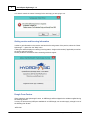


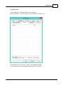
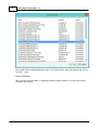

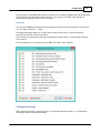


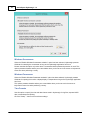
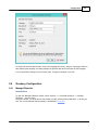
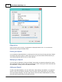

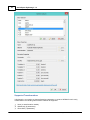


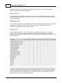

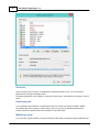


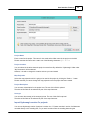
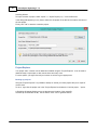

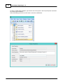


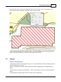


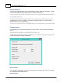
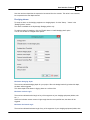
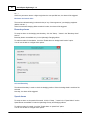


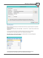
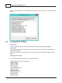


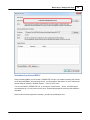
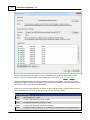

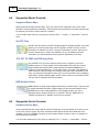

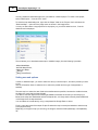


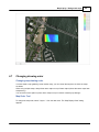
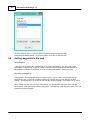


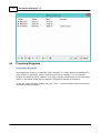

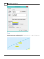
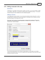


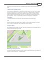
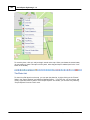


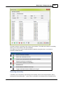

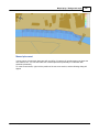
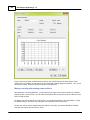
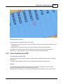


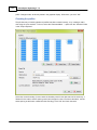
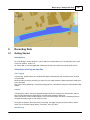


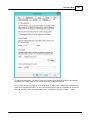
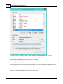
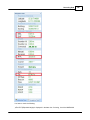


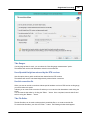

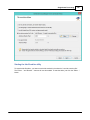


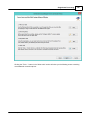

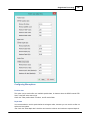


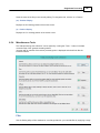

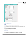


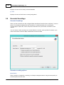


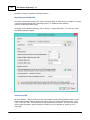

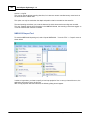


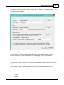
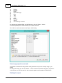
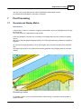


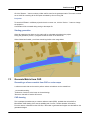
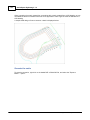
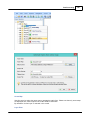
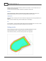


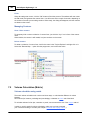
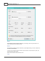

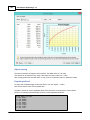


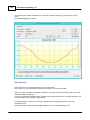


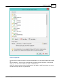
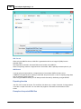


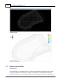
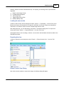
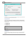

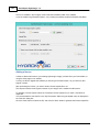
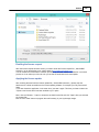
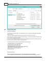


![U.S. Version [Last Updated on: Jun 13th, 2014]](http://vs1.manualzilla.com/store/data/005873845_1-0370c7761d3b42576ec2ae1fd24c9e75-150x150.png)