1
I)
61
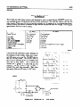
I/O System Introduction
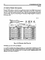
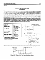
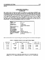
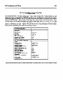
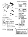
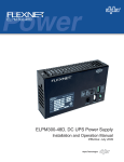
The Input/Output (I/O) of the Series One and Series One Plus PCs is provided on modules (figure 6-1)
each typically with 4,8, or 16 input circuits or 4,8, or 16 output circuits. These modules are inserted
into slots in the racks. Up to 4 modules in a 5-slot rack or 9 modules in a lo-slot rack of any I/O mix
can be placed in the first rack with the CPU. Up to 5 modules in a S-slot rack or 10 modules in a lO-slot
rack, again of any I/O mix can be placed in each of the expansion racks.
The I/O references are assigned to each slot by its physical position (see table 5-5). The only address
switches that need to be set are associated with the racks. In the S-slot rack, a 2 position switch must be
set which specifies whether the rack is a CPU or expansion rack. Series One Plus lo-slot racks have 2
bridge connectors, on the backplane, which must be set to specify whether the rack is a CPU or
expansion rack and the I/O addressing configuration for slot 10 of the CPU rack and all slots in the
expansion rack. Installation and wiring of these modules is discussed in Chapter 3, Installation. This
chapter will discuss the capabilities of these I/O modules, to allow the user to properly design wiring
diagrams and apply these modules.
62m
I/O Specifications and Wiring
GEK-90842
Field Wiring to I/O Modules
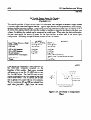
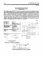
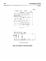
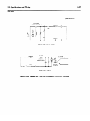
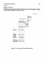
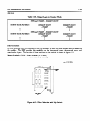
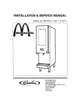
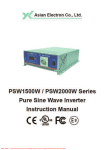
Each of the 8 circuit I/O modules, has a terminal block attached to it with 10 screw terminals. The 16
point YO modules, with screw terminals, have a removable socket type terminal board on the front of
the module. The terminal board can be easily removed, which allows modules to be readily removed or
changed without removing the field wiring to the module.
Each of these terminals are capable of
accommodating one AWG No. 12 or two AWG No. 14 stranded wires. A clear plastic cover snaps over
the terminals as a safety precaution. An insert is included with the covers to record circuit identification.
Some of the 16 point I/O modules are connected to field wiring through a connector
faceplate. A description of these modules is on the following page.
mounted
on the
The rest of this chapter provides specifications, wiring diagrams, typical schematics, and sample
reference numbers for each module type. The typical schematics are to provide details for interfacing
and not for maintenance or repair of these modules.
The sample reference numbers should be adjusted by the user to the actual slot in which the modules
will be installed. Every slot is provided with eight references. Those modules that provide eight circuits
still consume 8 J/O references.
When 4 circuit modules are used, the four references not used to
interface to “mil world” I/O, are available for use as internal references for the user’s logic program.
A 16 circuit I/O module uses 2 groups of 8 I/O references.
63m
I/O Specifications and Wiring
GEK-90842
a41 928
a40287
Figure 6-l. A. Typical I/O Module
B. High Density Module With Removable Connector
a40796
Cl 0
00
20
IO
30
40
50
60
70
00
O2
04
06
0 CB
01
03
05
C2 0
8 CIRCUIT
Fiire
07
CAo
IO
30
50
70
00
20
40
60
16 CIRCUIT
6-2. Typical I/O Terminal Configuration
64-
I/O Specifications and Wiring
GEK-90842
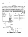
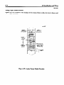
16 Circuit I/O Modules with Connectors
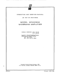
Some of the I/O modules providing 16 input or 16 output circuits have a 24-pin connector on the
faceplate. These modules are connected to user supplied input devices or user supplied loads through an
I/O Interface cable which is 10 feet (3m) in length (Catalog Number IC61OCBLlOS). One end of this
cable has a 24-pin female connector which mates with a 2kpin male connector mounted on the faceplate
of the I/O module. The wires on the opposite end of the cable are stripped and tinned for connection to
user devices. Each of the wires is color coded for easy identification. Figure 6-3 is a wiring list for the
I/O Interface cable.
a421 55
BUNE,
Aurd
12
12
321
ORN . .. .... ORANGE
GRA . . . . . SRAY
WHT ... . .. . WHITE
YEL . .. .. .. YELLOW
321
-N=Dl)
1
81
I
1
82
1
3
WHT (REDl)
B3
1
5
i
YEL (FtEDl)
84
1
7
lm
FWK (REDl)
ow=Da
-
-E-l-t871
PNK ....... PINK
RED ....... RED
BLK ....... BLACK
ORN (BLKl)
t
WHfmJw
t
YEL(BLK1)
I
PNK(BLK1)
1
-ww
I
1
t
GRA(BLK2)
1
I
ww~)
I
B8
I
3
B9
I
5
I
yw=w
I
7
1
PNK(BLK2)
1
c=wJw
=u~W
I
I
I A10
BlOI
Bll
10UuW+J
I Al2
812
bWU+I
Figure 6-3. I/O Interface Cable Wiring List
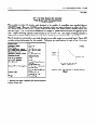
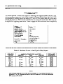
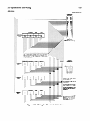
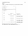
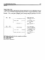
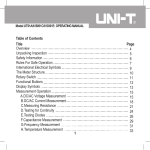
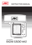
I/O References for 16 Circuit Modules
When using a 16 circuit I/O module, addresses are borrowed from future slots. The illustration in figure
6-4 is used as an example of this concept. For instance, if a 16 circuit module is installed in slot 02, the
I/O references for that module will be 020-027 and 120-127. Slot 12 is then no longer available for use
since its Teferences have been used (borrowed) by the module in slot 02. Additionalexamples of I/O
addressing can be found in Appendix B.
65m
I/O Specifications and Wiring
12Sl27
a40797
‘1
n
loo
TO
107
070
TO
077
w
m
TO
10
o[i7
olbl
MO
TO
150
TO
157
b
047
TO
007
140
TO
147
loo
TO
107
1
c
s
10 SLOT RACKS
EXAMmf
s#MSoNf
must
Figure 6-4. Example of 16 Circuit I/O References
NOTE
When using the maximum number of 16 point I/O modules possible, the slots marked with an X
are no longer available for system use.
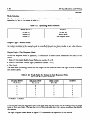
I/O Interface Cable Cross Reference List
The following list provides a reference to the available I/O Intetiace
with which they may be used.
cables and the module or modules
Cable Description
Module
IC61OCBL105
24 Pin Connector
10’ (3 meters)
IC61OMDLlO5
1C610MDL106
IC61OMDLl56
Thumbwheel Interface
High Density Input
High Density Output
IC61OCBL107
32 Pin Connector
10’ (3 meters)
IC61OhdDLllO
High Sped Counter
Description
I/O Specifications and Wiring
66I
GEK-90842
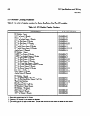
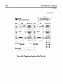
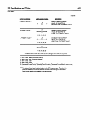
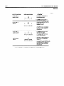
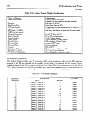
I/O Module Catalog Numbers
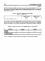
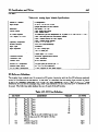
Table 6-1 is a list of catalog numbers for Series One/Series One Plus I/O modules.
Table 6-l. I/O Module Catalog Numbers
CATALOG
DESCRIPTION
NUMBER
I/O Modules - Input
115 V ac Input., 8 Circuits
230 V ac Input, 8 Circuits
115 v a.c Isolated Input, 4 Cixuits
24VdcSinkInput,8Cimits
24VdcSinkInput,16Circuits
24 V dc Sink Load Input, 16 Circuits
24 V ac/dc Source Input, 8 circuits
24 V ac/dc Source Input, 16 Circuits
Analog Input, 4 Channels
IC61OMDL125
IC61OMDL127
IC61OMDL126
1C610MDL101
IC61OMDL106 (2)
IC6lOMDL107 (1)
1C610MDL111
IC61OMDL112 (1) (3)
KXlOMDL116
I/O Modules - Output
115/230 V ac Output, 8 Circuits
115/230 v ac Isolated Output, 4 circuits
24 V dc Sink Output, 8 Circuits
24 V dc Sink Output, 16 Circuits
24 V dc Sink Output, 16 Ciraits
24Vdc2AmpSinkOutput,4Circuits
24 V dc 2 Amp Sink/Source Output, 4 Circuits
24VdcSourceOutput,8Circuits
24 V dc Source Output, 16 Circuits
Relay Output, 8 Circuits
Relay Output, 16 Circuits
Analog outpu& 2 Channels
IC61OMDL175
IC61OMDL176
IC61OMDL151
IC61OMDL156
IC61OMDLl57
IC61OMDL153
IC61OMDL154
IC61OMDLl55
IC61OMDL158
IcdlOMDLl80
IC61OMDL182
IC61OMDL166
I/O Modules - Special
24VdcI.nput/outpu~4In/4out
24 V dc Sink Input/Relay output, 4 In/4 Out
numbwheel In*
High Speed Counter
Fast Response l/O, 4 In/2 Out
I/o simtior,
8 Input Circuits
I/‘OModules-ULListed
115VacInput,6Circuits
Relay Output, 5 Circuits
115VacOutput,6Cimits
1. Ranovable tarnid
(2) ”
(1)
(1)
(1)
IC61OMDL103
IC6lOMDL104
IC61OMDL105 (2)
1C610nmL110 (4)
IC61OMDL115
1C610MDL124
IC61OMDL135
IC6lOMDL181
IC61OMDL185
board for I/o wiring.
2 Camectsto~thmugh24pinconn~rmfaccplatc.
3.
Thi6modn3.ccm~bcu6eda6a~inpuL
4. CameUstol/Othmugha32pin~~onfr#plate.
Theu6crmu6tprcwidcthepowcr~
to
operate
the
field devices.
67I
I/O Specifications and Wiring
I/O Module Specifications and Wiring
The remainder of this chapter describes the available I/O modules for the Series One and Series
One
Plus PCS.
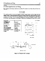
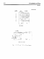
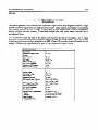
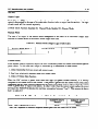
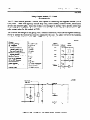
115 V ac Input
IC610MDL125
This module provides 8 circuits each designed to receive a single discqte
(ON/OFF) signal from user
supplied devices. Typical input devices include limit switches, pushbuttons, selector switches, and relay
contacts. The 8 circuits are divided into two groups of 4 circuits each. Each group can be supplied fkom
a separate power source. Power to operate the field devices must also be supplied by the user. Figure
6-5 provides wiring information for this module. Following are specifications for each of the 8 circuits.
Iuput Points
Operating Voltage
8
AC F’requency
Input current
Input Impedance
ON Level
OFF Level
OFF to ON Response
ON to OFF Response
Circuit Indicator
Internal Power Consumption
Units of Load
Weight
97-132 V ac
47-63 Hz
lSmA@6OHz
11.5 mA @ 50 Hz
9.5K ohms
Above 80 V ac
Below 20 V ac
10-30 ms
lo-60 ms
Field Side
lOmA@9Vdc
lUnit@9Vdc
5 02 (140 g)
T VPICAL
USER
MODULE
WlRlNG
REFERENCES
05c
051
052
053
-
054
055
056
057
WlRtNC
r -....,,q
I
II
I
I8
I
I
I
c-.
-*. c- (C---rm
INPUT
II
w
I
I
brrmr.--
115 VAC
0-N
(%L-,W,_
\r /
COMMON
TO OTHER
THREE CIRCUITS
COUPLER
SAMPLE
INPUT CIRCUIT
Figure 6-5. Wiring for 115 V ac Inputs
DIAGRAN’
m
68
I/O Specifications and Wiring
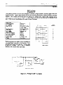
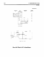
230 V ac Input
IC6lOMDLl27
This module provides 8 circuits, each designed to receive a single discrete (ON/OFF) signal from user
supplied devices. Typical input devices include limit switches, pushbuttons, selector switches, and relay
contacts. The 8 circuits are divided into two groups of 4 circuits each. Each of the 2 groups can be
supplied from a separate power source. Power to operate the field devices must also be supplied by the
user. Following are specifications for each of these 8 circuits.
pc-~1-84-0024
Input Points
8
opercltingvoltrrgc
18@265 V 15:
4763 Hz
18 mA (Za!W, 60 Hz),
Max.
llmA,TypicaI
18Kobms@6oHz
Above 180 V ac
BChW4OVpc
<2mA
5-50 ms
5-60 ms
Field Si&
lOmA,9V&
lUnit@9Vdc
5 02 (140 g)
AC Fhquency
Input current
InpPt Impcdrn=
ON Vdtage
OFF Voltage
OFF currart
OFF to ON Response
ON to OFF Response
circuit Indi~tcbrs
InPower chsumption
Units of Luad
Wdght
USER
MODULE
WIRING
TYPtCAL
REFERENCES
060
061
062
063
064
065
066
067
Field connections are made to screw terminals on
a terminal block mounted on the faceplate. Each
terminal will accept up to one No. 12 AWG wire
or two No. 14 wires. The Cl and C2 common
terminals are isolated from each other.
*-
WIRING
INPUT
r _ ___<>=-i.;___
I
1
I
I
I
I
I
I
180-265
VAC
I
t-1
L --I,---4r9~-rr-r
\ r#
COUPLER
TO OTHER e
THREE CIRCUITS
SAMPLE
INPUT CIRCUIT
Figure 645. Wiring for 230 V ac Inputs
DIAGRAM
’
69(I
I/O Specifications and Wiring
GEIWO842
115 V ac Isolated Input
IC610MDLl26
This module provides 4 circuits, each designed to receive a single discrete (ON/OFF) signal from user
supplied devices. Typical input devices include limit switches, pushbuttons, selector switches, and relay
contacts. Each of these circuits is isolated from the other circuits on this module relative to AC power
source. The tern isolation is not relative to optical-coupler noise and fault isolation which all I/O
modules have. Each input is provided with 2 field terminals allowing separate AC power sources (that
is, different phases) for each of the four inputs. The sources of AC power must be supplied by the user.
Figure 6-7 provides wiring information for this modules.
Although this module consumes 8 discrete references assigned to the I/O slot into which it is inserted,
only 4 are actually used. The other 4 can be used internally as coils, but they cannot be *provided to
hardware I/O modules. Following are specifications for each of the 4 circuits:
Input Points
4
97-132 v ac
4763 Hz
15ma@6OHz
10K0bms@60Hz
12K ohms @ 50 Hz
Above 80 V ac
Below 20 v ac
10-30 ms
10-60 ms
Eeld Side
lOmA@9Vdc
1@9Vdc
42 02 (120 g)
cm-t@
Voltrrge
AC Frequency
Input Current
hlput Iqaiance
ON Level
OFF Level
OFF to ON Response
ON to OFF Response
Cira& Indicator
Internal Power consumption
Units of Load
Weigtrt
TYPICAL
USER
WIRING
MODULE
REFERENCES
3C
37
32
33
WIRING
I-
___-
4
115
VAC
TI
b
SAMPLE
Figure
INPUT
OPTICAL
COUPLER
ClfXUlT
6-7. Wiring for 115 V ac Isolated Inputs
DIAGRAM
I/O Specifications and Wiring
6-10
GEK-90842
24 V dc Sink Input (8 Circuits)
IC610MDLlOl
This module provides 8 circuits each designed to receive a single discrete (ON/OFF) signal from user
supplied devices. Typical input devices include limit switches, pushbuttons, selector switches, and relay
contacts. Power (24 V dc) to sense the state of these inputs is provided by the rack power supply. No
external power source is required with this module. All 8 circuits are powered from this one source.
Figure 6-8 provides wiring information for this module. Following a~ specifications for each of the 8
circuits:
8
Input Points
Maximum Voltage
36 V tic
TYPICAL
(open Ci=uit)
Input Current
Inpat Impedance
USER
WIRING
18 nA
1.8 K ohms
<3vdc
>3V&
4 to 15 ms
4 to 15 ms
Field Side
ON Level+
OFT Leve!P
OFF to ON Response
ON to OFF Response
CircuB Indicator
Maximum OFF Leakage
llainimum ON current
IElterMl Power consumption
REFERENCES
MODULE
046
04:
042
3mA
7mA
043
044
14mAforcachON
CiIwit@24Vdc
lOmA@9Vdc
1@9Vdc
lo@ 24 V &
4.2 02 (120 g)
Units of Load
Weight
045
046
_
1
* Voltage levels measured between common and input termin&
(across input device).
WIRING
I
I
L
-e
-
-
-
,.‘f
.
COUPLER
SAMPLE
INPUT CIRCUIT
Figure 6-8. Wiring for 24 V at Sink Inputs
DIAGRAM
047
INTERNAL
CONNECTlOhi
II0 Specifications and Wiring
641
GEK-90842
24 V dc Sink Input (16 Circuits)
IC610MDL106
This module provides 16 circuits, each designed to receive a single discrete (ON/OFF) signal from user
supplied devices. This module has 16 LED status indicators to reflect the ON or OFF status of each of
the 16 circuits. Typical input devices include limit switches, pushbuttons, selector switches, and relay
contacts.
24 V dc power to sense the state of these inputs is provided by the rack power supply;
therefore, no external power source is required for this module. All 16 circuits are powered from this
one source.
Figure 6-10 provides wiring information for this module. The 16 input circuits a~ connected to user
devices through a 240pin connector. An optional I/O Interface cable, catalog number IC61OCBL105, is
available for use with this module. Following are snecifications for each of the 16 circuits:
Input Points
Maximum Vokage
(open C~cw
Input current
ON Level
OFF Levd
OFF to ON Response
ON to OF’F Response
Maximum OFF Leakage
Minimum ON Current
Circuit Indhtor
Internal Power Consumption
Units of Load
Weight
a40566
16
36 V dc
16 nd
ot03vcic
18 to 36 V tic
4 to 15 ms
4 to 15 ms
2mA
5mA
Field side
24 IIA @ 9 V dc, Max.
(16 circuits ON)
210 ltliq @ 24 v tic, Max
(16 circuits ON)
3uIlits@9Vdc
21units@24vcic
42 02 (120 g)
MODULE
TYPICAL
REFERENCES
A
a40548
I6
NUMBER
OF
55%
t I6 CIRCUITS ON)
I3 CIRCUITS ON
it -
clR~~lTS 8 -
10% 20% 30%
40% 50%
60%
AUBIENT TEMPERATURE I%1
Fiire
6-9. I/O Points VS Temperature
r---------
-
OPTICAL
COUPLER
SAMPLE
INPUT CIRCUIT
Figure 6-10. Wiring foi* 16 CIRCUIT, 25 V dc Sink Input Module
B
030
031
032
033
034
035
C36
037
130
131
132
133
134
135
136
737
6-12
II0 Specifications and Wiring
_
GEK-90842
24 V dc Sink Load Input (16 Circuits)
With Removable Terminal Board
IC6lOMDL107
This module provides 16 circuits, each designed to receive a single discrete (ON/OFF) signal fkom user
supplied devices. This module has 16 LED status indicators to refiect the ON or OFF status of each of
the 16 circuits. Typical input devices include limit switches, pushbuttons, selector switches, and relay
contacts.
24 V dc power to sense the state of these inputs is provided by the rack power supply;
therefore, no external power source is required for this module.
The 16 circuits are divided into 2
groups, with each group having its own common terminal. The 2 common terminals a~ tied together
internally.
Figure 6-12 provides wiring information for this module.
devices through a removable socket type temxinal board.
The 16 input circuits are connected
to user
a40799
Input Points
Maximum VoItage (Open
CbCUit
In t 2 urrent
OIrLtvel l
OFF Level +
OFF to ON Response
ONtoOFFR
Maximum OFF
=YliGge
Minimum ON Current
Circuit Indicator
IntemaI Power Consumption
Units of Load
Wew
16
36 V tic
USER
WlRlNG
MODULE
USER
WIRING
17 mA
otQ3vdc
19to24vdc
3 to 15 ms
TYPICAL
REFERENCES
;~5,s
Field Side
25 mA @ 9 V dc,
Maximum
(16 circuits ON)
14 mA for each ON circuit
@24V&
3units@9v&
23 units
24vdc
6.0 oz (1? 0 g)
lVohqe
levels measured betwtar
teiimbab (across input device).
043
046
140
142
common and input
a40790
144
146
\r
9 CIRCUITSON
10%
20% 3oT
WIRING
DIAGRAM
40% SOT 60%
AMBIENT TEuPERAfURE
I *Cl
Figure 6-11. I/O Points VS Temperature
POWER SUPPLY
047
=3
OPTKAL(__
COUPLER
Figure 6-12. Wiring for 1OrCircuit, 24 V dc Sink Load Inputs
I/O Specifications and Wiring
64.3
GEKm842
24
V ac/dc Source Input
IC610MDLlll
This module provides 8 input circuits, each designed to receive a single discrete (ON/OFF) signal from
user supplied devices. Typical input devices include pushbuttons, limit switches, selector switches and
relay contacts. These input circuits can interface to either 24 V ac signals or 24 V dc source-type signals,
thereby allowing the module to interface to input devices that provide their own voltage. Following are
specifications for each of the 8 circuits.
Input
AC INPW
20 to 28 V ac, 50-60 Hz
19 mA (maximum)
13mA Typical
2oto28vac
Oto6Vac
5 to 50ms
Sto6Oms
Field Side
Voltage
Input current
ON Level
OFF Level
OFF to ON Response
ON to OFF Response
Circuit Indicator
InPower Consumption
Units of Load
weight
DCINPUT
20-28 v dc (Source)
19 mA (maximum)
13mA Typical
2oto28vdc
Oto6Vdc
6 to 30 ms
StchOms
Eeld Side
9 V dc, 10 mA (supplied by rack powa supply)
1@9Vdc
5 02 (140 g)
a42681
USER
User devices are connected to screw terminals on
the faceplate of this module. Each screw terminal will accept up to one No. 12 AWG wire or
two No. 14 AWG wires. The ON/OFF state of
each circuit is indicated by an LED located in the
field side of each circuit. The 8 circuits are
divided into 2 groups of 4, each with its own
common.
The two commons, CA and CB are
isolated from each other intexnally. Each input
can accept either an AC input or a DC input.
1
a42682
WIRING
+
.1
AC
1
(CA
CBI
Figure 643. Wiring for 24 T’ $c/dc hputs
/
TYPICAL
MODULE
WIRING
OIAGRAM
REFERENCES
03C
031
032
033
034
035
036
037
6-14
I/O Specifications and Wiring
GEK-90842
24
V ac/dc Source Input (16 Circuits)
With Removable Terminal Board
IC610MDLllZ
This module provides 16 input circuits, with LED indicators, each designed to receive a single discrete
(ON/OFF) signal fkom user supplied devices. Typical input devices include pushbuttons, limit switches,
selector switches and relay contacts. These input circuits can interface to either 24 V ac signals or 24 V
dc source-type signals, thereby allowing the module to interface to input devices that provide their own
voltage. In addition, the module can be connected as a sink input. When using the sink configuration,
the user must supply the source of power for the input devices, as when used in the source input
configuration.
Following are specifications for each of the 16 circuits.
Input
VoMage (source or Sink)
Input current
ON Level
OFF Level
OFF to ON Response
ON to OFF Response
Circuit Indicator
Intemal Power Consumption
ACIWUT
14 to 30 v ac, 50-60 Hz
12mA@24Vac
14 to 30 v ac
oto3vac
5 to 30 Ins
5 to 30 ms
Logic Side
Units of Load
wei%lt
DCKNPUT
20-28 V dc
12mA@24&
14 to 30 v tic
oto3vdc
5 to 25 ms
5to25ms
Logic Side
9 V dc, 130 mA (maximum)
Typical, 25 mA + 4.5 mA for each ON circuit
13
6 oz (170 g)
a40800
User devices are connected to screw terminals on
the removable
connector
mounted
on the
faceplate of this module.
Each SCRW terminal
will accept up to one No. 12 AWG wire or two
No. 14 AWG wires. The On/OFF state of each
circuit is indicated by an LED located in the logic
side of each circuit. The 16 circuits are divided
into 2 groups of 8, each with its own common.
The two commons, CA and CB a~ isolated fkom
each other internally.
Each input can accept
either an AC input or a DC input.
I6 CIRCUITSON
I6
NUMBER
12 -
OF
CIRCUITS
ON
*-
IO CiRC'JiTS
ON
7 CIRCUITSON
5 CIRCbiTSOh
49
I
I
IO’C
ZO’C
AMKENT
I
30%
1
4O'C
1
SOY
!
6O'C
TEMPERATURE ('Cl
F’iiiigure
6-14. I/O Points vs Temperature
chart
I/O Specifications and Wiring
6-15
GEK-90842
a40801
USER WIRING
I
USER WIRING
MODULE
r
1
--b
Fb,
14 - 30VAC
I
NPICAL
REFERENCES
010
011
012
013
3
014
015
5
016
017
0
111
110
2
113
112
4
115
114
6
117
116
CA
0
0
2
4
6
7
CB
3
5
7
WIRING
DIAGRAM
INPUT (O-7)
_~__”
8
t
1
-’
’
I
I
A@
t’
DC
OR
$
;
J.
'Y
I
::.:;
.
-r’8
.rdr-r-
AC
COMMOC
OPTICAL
(CA, CB)
SAMPLE INPUT CIRCUIT
FIGURE 6 15 WIRING FOR 16 CIRCUIT 24 VAC/DC
LOAD INPUTS
SOURCE
Figure 6-15. Wiring for 16 Circuit 24 V ac/dc Source Load Inputs
II0 Specifications and Wiring
6-16
GEK-90842
115&O V ac Output
IC610MDL175
This module provides 8 circuits each capable of controlling user supplied discrete (ON/OFF) loads.
Typical loads include relay coils, motor starters (up to No. 3), solenoid valves and indicator lights. The
8 circuits a~ divided into 2 groups of 4 circuits each. Each group can be supplied from a separate
power source. Power to operate the field devices must also by supplied by the user. Figure 6-17
provides wiring information for this module. Following are specifications for each of the 8 circuits:
t
I
1 CAUTION ]
If this module is wired incorrectly or the listed specifications are exceeded, any damage
incurred by the module or user devices connected to the module may not be covered by
warranty.
output Points
8
97-265 V x
4763 Hz
1 =lP
1.2 mA
220v, 60 Hz
0.5 IxUi 8 llOV, 60 Hz
0.9v
1 -P
0.W 8 0.5 amp
25 mA
10 amps for 16 ms
5 amps for 100 ms
1 ms
8-10 ms (l/2 cycle)
Logic Side
(2) 5 amp fast blow (one
cmeach
up of 4)
ON
20 mA gkach
ciIalit
9vdc
16@9 % ck
6.4 oz (180 g)
ting Voltage
OE?-Fkquency
A
Maximum Current*
Maximum Leakage Current
ON Vdtage
Drop
Smallest Recommended
Maximum Inrush
Load
OFF to ON Response
ON to OFF Response
Circuit Indicator
m
(Internal, Soldered)
Power Consumption
Memal
Units OaLoad
Wdght
*Maximum load current is dependent upon ambient
temperature as shown on the chart in @are 6-16.
8 CIRCUITSON AT I AMP EACH
I
\
8
ON
4
MODULE
5 CIt?CUITS
ON
A? 2.5
3 CIi?CUiTS
AT
oh
AYBIEhT
97-265
VAC
054
055
056
057
EACH
AMPS
DIAGRAM
EACH
I ALAP EActr
TEUPEG~TURE ~'Cl
97-265 VAC
0ma
l
m-
F’iire
VAC
053
6-16. I/O Pomts vs Temperature
TO OTHER
THREE ClRCWS
97-265
052
10% 20% 30't 40'::50% 60%
Figure
WIRIfvG
050
WIRING
\\
USER
051
a40555
Cif?CUITS ON AT 0.5 AUPS
..
\\
\\
\\
NUMBER 6
3F
CIRCltITS
TYWCAL
REFERENCES
6.17. Wiring for 115/230 V ac Outputs
II0 Specifications and Wiring
6-17
1151230 V ac Isolated Output
IC610MDL176
This module provides 4 circuits each capable of controlling user supplied discrete (ON/OFF) loads.
Typical loads include relay coils, motor starters (up to No. 4), solenoid valves, and indicator lights.
Each of these circuits is isolated from the other circuits on this module relative to AC power source.
The term isolation is not relative to optical-coupler noise and fault isolation which all I/O modules have.
Each output is provided with 2 field terminals allowing separate AC power sources (that is, different
phases) for each of the 4 outputs. These power sources must be supplied by the user. Figure 6-19
provides wiring information for this module. Although this module consumes 8 discrete references
assigned to the slot into which it is placed, only 4 are actually used. The other 4 can be used internally
as coils, but they cannot be provided to hardware I/O modules. Following are specifkations for each of
the four circuits:
PC-Sl-83-0038
Outputs
ting VoWP
T- Frequency
A
Msucimum Current*
lblaximara Leakage Current
4
97-265 V IIC
4763 Hz
2ams
7J@22OV
6oHz
3.5 ITA
11ov
20 ampsY or 16 ms
.8V @ 2 amps
25 IIA
1.0 ms
8-10 ms l/2 Cycle)
Logic SiL
(4) 3 amp fast blow
Maximum Inrush
ONVd
eDrop
Sxnabst ?I ecommended Load
OFT to ON Response
ON to OFF Response
Circuit ladiabtor
(In-W
(each circuit, Replaceable)
Inter& Power Consumption
Units of bd
WWt
12 mA
8uni1s
5=(1 f
TYPICAL
REFERENCES
MODULE
60
61
62
9vdc
9Vd.c
g)
63
* Maximum load current is ckpcndcnt upon ambient temperaWe
asshownanthechaftinfi~6-18.
-
a40549
4 CIRCUITSOn AT 2 AUK EACH
4
-k\
\
IRCUITSon AT I AMPEACH
‘\
‘\
WIRING
10% 20% 30-c
AMWENT
40% 50%
TEMPERATURE
DIAGRAM
jwc
t %I
Figure 6-18. I/O Points vs Temperature
Chart
115
VAC
p&L;______________:::;_____:
Figure 6-19. Wiring for 15 V ac Isolated outputs
USER
WIRING
I/O Specifications and Wiring
6-18
24 V dc Sink Output (8 Circuits)
IC6lOMDL151
This module provides 8 circuits each capable of controlling user supplied discrete (ON/OFF) loads.
Typical loads include relay coils, motor starters, solenoid valves, and indicator lights. The 8 circuits are
provided referenced to a single DC power source, that must be supplied by the user. Figure 6-21
provides wiring information for this module. Since current flows from the load into the field tetial
for
each circuit when the output is energized, these circuits are referred to as sink DC outputs. Following
are specifications for each of the 8 circuits:
I
oatput POWS
Operatiqg Vokage
PeakVd
e
MaximumT urrent*
current
MaKLULk
ON VoltageTro p
SmaIkst Recommended Load
MaxbwmInrush
OFF to ON Response
ON to OFF Response
Circuit India&w
Fuses o[n-)
Power Consumption
Intemal
Units of Load
Weight
8
5-24 V &
45 v dc
0.5 am
T’fPlCAL
REFERENCES
4ovcic
0.8V @ d .5 amp
0.65V @ 0.1 amp
1 mA
3 amp for 20 ms
1 amp for 100 ms
100 msec
100 m8cc
Logic Side
(2) 3 =p
(one on each oup of 4:)
USER
MODULE
0.lrn.z
20 mA @ 9 Tic.
3mAforeachON
circuit a24vdc
2uIlits
s vdc
24 V dc
3uIlits
42 02 (e 20 g)
5-24
l
WIRING
VDC
plot
Cl
+
060
A
1
061
062
063
064
065
066
067
L
INTER&AL
/
CONNECT1Ob
Max. load current is dependent upan ambient temperatures as
shown in fig. 6-20.
*
a40550
WIRING
8
I
NUFR
CYFTS
DIAGRAM
8 CIRCUITSON AT 0.5 AMPSEACH
y
9 8 CIRCUITSON AT .3S AMPS EACH
\\
\\
\\
6
‘1, S CIRCUITSON AT 0.5 AYK EACH
’ 2.
Figure 6-20. I/O Points vs Temperature
24 VDC
Chart
INTERNAL
POWER SUPPLY
VDC
I
I
3A
I
,
I
OPTICAL
COUPLER
F’igure 6-21. Wiring for 24 V dc Sink Outputs
I/O Specifications and Wiring
6-19
GEK-90842
24
V dc Sink Output (16 Circuits)
IC610MDL156
This module provides
16 circuits, each designed to be capable of controlling user supplied discrete
(ON/OFF) loads. There are 16 LEDs on the faceplate, which ase status indicators to reflect the ON or
OFF status of each of the circuits. Typical loads include relay coils, motor starters, solenoid valves, and
indicator lights. The 16 circuits are referenced to a single DC power source that must be supplied by the
user. Output switching capacity of this module is 0.5 A ti 24 V dc. The output switching circuitry is
arranged in 4 groups with 4 circuits in each group. Each group is protected by a 3 amp fuse.
The 16 circuits are connected to user loads through an optional I/O Interface cable, Catalog number
IC61OCBLl05, which connects to a 24.pin connector mounted on the module faceplate. Figure 6-23
provides wiring information for this module. Following are specifications for each of the 16 circuits.
16
5-24 v dc
40VdC
0.9 v tic
0.5 amp
1.5 v dc
0.5 amp
0.5 am
0.1 In&@ 40 v dc
3 amp for 20 ms
1 amp for 100 ms
0.1 ms
0.1 ms
3=p&output
Common Line, one for
each
up of 4).
4omjpo@9Vdc,
MaximUm
16 outputs 0
v dc,
66 mA@24
MaximUm
(16 outputs ON)
4units@9Vdc
24vdc
10 units
3.9 02 (1e 0 g)
output Points
p
ical
ON Voltage Drop,
urn
ON Voltage Drop,
Maximum Current*
Maximum Leakage Current
Maximum Inrush
a&l
OFF to ON Response
ON to OFT Response
Fuse (Iarnal)
Internal
Units
Power Consumption
of Load
Wlaximum
load current is dependent
upon ambient
temperature
8s shown in figure 622
16-+yPC
(16 CIRCUITS
IO% 20%
AYBIENT
Fiire
30%
USER
WIRING
USER
WIRING
MODULE
C
WIRING
DIAGRAM
OnI a40552
40% 50% 60%
TEMPERATURE
(73
6-22. I/O Points vs Temperature
Chart
24
+r
POWER
VDC
I -
SUQPLY
Figure 6-23. Wiring for 16 Circuit 24 V de Sink Outputs
TYPICAL
REFERENCES
A
B
030
031
032
033
034
035
036
037
I/OSpecifications and Wiring
6-20
GE&90842
24 V dc Sink Output (16Circuits)
With Removable Terminal Board
IC6lOMDL157
This module provides 16 circuits, each designed to be capable of controlling user supplied discrete
(ON/OFF) loads. There are 16 LEDs on the faceplate, which are status indicators to reflect the ON or
OFF status of each of the circuits. Typical loads include relay coils, motor starters, solenoid valves, and
indicator lights. The 16 circuits are referenced to a single DC power source that must be supplied by the
user. Output switching capacity of this module is 0.5 A at 24 V dc. The output switching circuitry is
arranged in 2 groups with 8 circuits in each group. Each group is protected by a 3 amp fuse.
The 16 circuits are connected to user loads through a removable socket type terminal board. Figure 6.25
provides wiring information for this module. Following w specifications for each of the 16 circuits:
output Points
Operating Vokage
Peak Voltage
ON Voltage Drop, Typical
011’ Vobage Drop, Maximum
Maximum Current+
Maximum Leakage Current
Maximum Inrush
OFF to ON Response
ON to OFF Response
Fuse (Internal)
Internal Power Consumption
Units of Load
Weight
16
5-24VdC
4OVdC
1.0 v dc @ 0.5 amp
2.0 V dc @ 0.5 amp
0.5 amp
0.11 mA @ 40 v dc
3 amp for 20 ms
1ampforlCXIms
0.1 ms
0.1 ms
3 amp (In Output Common
L&e, one
for each group of 8)
9 V dc: 3 mA + 2.3 mA for
each ON circuit
24Vdc:dmAforeachON
circuit
4uIlits@9V&
1ouxlits@24vdc
5.6 02 (160 g)
* Maximum load current is dcpcncknt
as shown in figure 6.24.
upon ambient tcmperatwe
a40802
IO'C
2O'C
3C'C
M'C
5O'C
6O'C
Figure 6-24. I/O Points vs Temperature
Chart
II0 Specifications
6-21
and Wiring
a40803
MODULE
USER WIRING
USER WRING
c
r---
‘5-24vDC
056
057
150
152
156
The following
rules should be used when applying this module.
1 . Each group of 8 outputs is limited to 2A total curxnt.
2 . The maximum current for each array of 4 outputs (O-3), (4-7) is:
2 points on - .5 amps each
4 points on - .35 amps each
1 point on - .7 amps,
3 points on - .4 amps each,
VDC
24VDC
I
I
I
I
I
I
I
I
I
I
I
I
t
I
POWER SUPPLY
_d(~,__.w..0l
OUTPUT
SAMPLE
OUTPUT CIRCUIT
Figure 6-25. Wiring for 16 Circuit 24 V dc Sink Outputs
I/O Specifications and Wiring
6-22
24 V dc 2 Amp Sink Output
IC610MDL153
This module provides 4 fused 24 V dc sink output circuits each capable of controlling user supplied
discrete (ON/OFF) loads. Each circuit is rated at 2 amps continuous current. Typical loads include
motor starters, relay coils, solenoid valves, and indicator lights. The circuits on this module are referred
to as sink outputs since current flows &om the load into the field terminal for each circuit when the
output is energized. Field connections are made to screw terminals on a terminal block mounted on the
faceplate. Each terminal will accept up to one No. 12 AWG wire or two No. 14 AWG wires. The
ON/OFF state of each circuit is indicated by a corxqxxrding LED. This module, although having only
4 output circuits, will consume 8 consecutive discrete references.
The 4 references not available as
“real world” outputs can be used as internal coils. Following are specifications for each of the four
output circuits.
Output Points
Operating Voltage
Peak Voltage
ON Voltage Drop
Maximum Current*
Maximum Leakage Current
OFF to ON Response
ON to OFF Response
Circuit Indicator
Fuses, Internal
Internal
Power Consumption
4
5to%V&
45 v &
.15Vdc@larrnp
.6Vdc@4amp
2 amps
<.4mA@4OVdc
.l ms
.l ms
Logic Side
5 amp (1 for each circuit)
Replaceabk
5 mA @ 24 V tic
l2mA@9Vdc
&hits of Load
1unit@24vdc
Waw
2units@9Vdc
4.2 02 (120 g)
*Maximum
load cumnt
TVPICAL
FIEFEREWES
MODULE
is deucndmt
USER
a4055 1
4 CIRCUITS ON AT 2 AMPS EACH
4 CIf?CUITS ON AT I AMP EACH
4
NuFR
3
CIRFTS 2 I-
x.3 CIf?CUITS
ON AT
‘\4AYK EACH
3 CIWUITSONAT2 AMPSEACH
'\
'\'\
'l
.\
'\
1CIR~UWIT'JN
Ai'\,
'\
'\.
Figure 6-26. I/O Points vs Temperature
Chart
cm ambient tcm~rature
as shown in fiare
6.26.
WlRMG
5A
OPTICAL
OX!
031
C
5
VDC
24
70
VDC
OUTPUT
1
032
5 TO 24
CIRCUITS
033
SAMPLE
SINK
OUTPU?
Figure 6-27. Wiring for 24 V dc 2 Amp Sink Outputs
CtKUlT
V/DC
I/O Specifications and Wiring
6-23
GE&90842
24 V dc 2 Amp Sink/Source Output
IC610MDL154
This module provides 4 isolated, fused 24 V dc sink or source output circuits each capable of controlling
user supplied discrete (ON/OFF) loads. Each circuit is rated at 2 amps continuous current. Outputs can
be connected in parallel to increase output cunxsnt capacity. Types of loads that can be controlled by
this module would include motor starters, relay coils solenoid valves, and indicator lights. All 4 circuits
can be referenced to a separate DC source of power. The circuits on this module can be used as either
source outputs or sink outputs, depending on how the load is wired in relation to the load power supply.
Field connections are made to screw terminals on a terminal block mounted on the faceplate. Each
terminal will accept up to one No. 12 AWG wire or two No. 14 AWG wires. The ON/OFF stateof each
circuit is indicated by a corresponding LED on the logic side. This module will consume 8 consecutive
discrete references. The 4 references not used as “real world” outputs can be used as internal coils in
your program. Following are specifications for each of the four circuits.
a40553
output POWS
oparrting
vow
Peak Vohage
curreut+
Maximum
MsuimumLeakage
ON Vohage Drop
Current
OFT’ to ON Respouse
ON to OFF Respouse
Circuit Iudicator
Fuse!& Iuterual
Iuterud
Lamp
Power cousumed
bad
should
*Loadament(max.)is
be
4
sto24vdc
45 v dc
2 amps cartinuous
8 amps Maximum Peak
<.4mA@4oVdc
lVdc@damps
~.6 V dc @ 4 amps
.3Vdc@Zamps
, .15 v dc @ 1 amp
~.l ms
.l ms
Logic Side
5 amp (1 for each circuit)
Replaceable
l2mA@9Vdc
3QmA@24VdC
2units@9V&
3units@24vdc
CIRClJITS
ON AT2 AUF'SEACH
4
4
NslJeER 3
OF
7
'..
‘\\ .
CIRCUITS
ON
2I
I
I
I1
10% a'(: 30%
AT ! AMP
EACH
\
h 2 CIRCUITSON AT 2 AMPS EACH
% .
\
'..
'.
I CIRCUITON Ai*
4AUPS
i
9 4 CIRCUITSON
\
\
\
\
\
\
\
'-,\3 CIRCUITSON AT
‘~4AMf5
EACH
j
I
ro@c 50%
AMBIENT TEMPERATURE
60%
i ‘CJ
Figure 6-28. II0 Points vs Temperature
TYPICAL
RLCERLNCLS
USER WmNG
MODULE
pc-~1-84-0023
.8 lDIip6 or less.
dependentonambient
050
temperature 8s shown below.
051
052
5 ‘C
24
dDC
SO@Cf
OS3
Although not shown IS such, the 4 circuits a~ isolated from each other and can be connected to separate power sources.
OPTICAL
SA
OUTPUT
--
COMMON
-
Figure
6-29. Wiring
--
of 24 V dc 2 Amp Sink/Source Output
I/O Specifications and Wiring
644
GE&90842
24
V dc Source Output
IC6lOMDL155
This module provides eight 24 V dc source output circuits, each capable of controlling
user supplied
discrete (ON/OFF) loads. Each circuit is rated at 0.5 amps continuous current. Typical loads that can
be controlled by this module are motor starters, relay coils, solenoid valves, and indicator lights. The
output switching circuits on the module are arranged in 2 groups with 4 circuits in each group. Each
group of 4 output circuits is protected by a 3 amp fuse. All 8 circuits should be referenced to a single
source of dc power. Field connections are made to screw terminals on a terminal block mounted on the
module’s faceplate. Each terminal will accept up to one No. 12 AWG wire or two No. 14 AWG wires.
The operating state, either ON or OFF, is indicated by a corresponding LED viewed on the module’s
faceplate. Following are snecifications for each >f the 8 circuits.
A
Output Points
&berating voltage
Peak Voltage
ON Vokage Drop
Maximum Current*
Maximum Leakage Current
Smallest Recommended Load
OFF to OX Response
ON to OFF Response
Circuit Indicator
Fuses (Intemal)
Inted
Power Consumption
Units of Load
wwt
a40554
8
sto24vdc
4OVdc
1.0 v @ 0.5 amp
0.75 v @ 0.1 amp
0.5 amps
O.lmAat24Vdc
1.0 mA
6 CIRCUITSON
1OOcLsec
100 jlsecs
Logic Side
(2) 3 amp (in output
common line,
one for each group of 4
circuits)
3OmAmaximum@9Vdc,
Supplied by rack power
I
on ambient tempexature
,
AMBIENT
,
,
,
3O'C 401: 50%
60%
TEMPERATURE Xl
Figure 6.30. I/O Points vs Temperature
Chart
mPplY
3Units@9Vdc
4.2 oz (120 g)
*Maximum load current is dependent
shown in figure 6.30.
,
10% 20%
as
II0 Specifications and Wiring
6125
a40626
TYPICAL
USER
MODULE
REFERENCES
5-24
WIRING
VDC
030
031
032
033
034
035
036
037
INTERNAL
/
CONNECTION
WIRING
TO
DIAGRAM
OTHER
3 CIRCUITS
COMMON
CA
OPTICAL
A
_______
w
3A
5 TO 24
+a
a,‘,‘,”
I ‘I’,’
It
-
VDC
-
_
_
a
_
_
7
I
I
t
TO
c
I
I
I
CB
b
LED
o-
--~~~~~~~~~-~
OUTPUT
SAMPLE
OUTPUT
CIRCUIT
Figure 6-31. Wiring for 24 V dc Source Outputs
--_
II0 Specifications and Wiring
6-26
GK-90842
24 V dc Source Output (16 Circuits)
With Removable Terminal Board
IC610MDL158
This module provides sixteen 24 V de source output circuits, each capable of controlling user supplied
discrete (ON/OFF) loads. The output switching capacity of this module is 0.5 amps at 24 V dc. Typical
loads that can be controlled by this module are motor starters, relay coils, solenoid valves, and indicator
lights. The output switching circuits on the module are arranged in 2 groups with 8 circuits in each
group. Each group of 8 output circuits is protected by a 5 amp fuse. All 16 circuits can be referenced to
a single source of dc power or each group of 8 can be referenced to a separate source of power. Field
connections are made to screw terminals on a removable terminal board mounted on the module’s
faceplate. Each terminal will accept up to one No. 12 AWG wire or two No. 14 AWG wires. The
operating St&e, either ON or OFF, is indicated by a corresponding LED viewed on the module’s
faceplate. Following are specifications for each of the 16 circuits.
a40805
output Points
~pgpitfns
VowiF
Peak Voltage
ON Voltage Drop
Maximum Current+
Maximum Leakage Curnnt
OFF to ON Response
ON to OFF Response
Circuit Indicator
Fuse!S (Internal)
16
5to24vdc
40VdC
Maximum 1.5 v dc
0.8 v dc
0.5 amp (Ty@al)
0.7
a- v dc 8 0.1 amp (Typical)
us am
MODULE
USER WIRING
?YPlCAL
I
5-24
6
10 m R
40 v dc
0.1 I&
csistive
1.0 ms B esistive 1
Logic Side
'(2)
5 amp (in output common
be, one for each group of 8
&Wits)
laterpal Power CcMwumption 12 mA for each ON circuit
Units of Load
Weight
V DC
REFERENCES
CA
0
020
021
1
022
023
3
024
025
5
026
027
0
121
120
2
123
122
4
125
124
6
127
126
2
0
4,
USER WIRING
4
A
6
5-24 V DC
7
I
0
CB
1
3
*Maximum load current is dependent
shown in figu~ 6.32.
on ambient tcrnpcraturc
-\
a40804
16 CIRCUITS
I6
ON
0.2%
NUMBER
OF
C*REYs
I2
o.sA,,
8
\\
\
as
5
7
10 CIRCUiTSON
WIRING DIAGRAM
1
IOT
20%
I
30%
1
40%
1
SO'C
AMBIENT TEMPERATURE
60%
I lCI
Figure 6-32. I/O Points vs Temperature
F’iire 6.33. Wiring for 24 V dc Source Outputs
I/O Specifications and Wiring
6-27
GE&90842
Relay Output (8 Circuits)
IC610MDLl80
This module provides 8 circuits each capable of controlling user supplied discrete (ON/OFF’) loads.
Typical loads include relay coils, motor starters, solenoid valves, and indicator lights. Since this module
is not designed for a specifk current type such as 115 V ac or 24 V dc, it can be used with a wide variety
of loads and signal types. The 8 circuits are divided into two groups of 4 circuits each. Each group can
be supplied from a separate power source. Power to operate the field devices must also be supplied by
the user. Following are specifkations for each of the eight circuits:
outputs
Operating Voltage
AC Frequency
Maximum Current*
M&mum
Leakage Current
(Across Contacts)
Smakst Recommended Load
MaximumInrush
OFF to ON Response
ON to OFF Response
Circuit Indhhtor
Fuses (Inteti)
InternskI Power Consumption
Units of Load
weight
8
5 to 265 V ac/dc
4763 Hz
4 amp (resistive)
1mA
5mA
5 amps
5 ms
5 ms
Logic Si&
(2) 10 amp (Replaceable)
(one for each group of 4)
45 II-LAfor each ON
circuit@9vdc
34unit.s@9Vdc
7 02 (200 g)
*Since non-solid state devices are used as the power switching devices, the following bitations
must be observed for z&able operation:
Table 6-2. Maximum Current vs Load Type for Relay Outputs
OPERATING
I
MAXIMUMCURRENT FOR LOAD TYPE
VOLTAGE
RESISTIVE
220 v ac
22ovac
11ovac
110 v ac
24 v dc
50 v dc
4.0 Amp
1OOVdc
250 V dc
4.0 Amp
I
SOLENOID
0.5 Amp
.05 Amp
0.5 &np
0.1
Amp
5.0 Amp
0.5
Amp
1.0 Amp
0.1 Amp
05 Amp
0.3 Amp
.05 Amp
.03 Amp
0.5
.05
0.5
0.1
0.5
0.1
.05
.03
Amp
Amp
Amp
Amp
Amp
Amp
Amp
Amp
TYPICAL LIF’E
(OPERATIONS)
100,ooo
800,000
150,000
650,000
100,ooo
100,ooo
100,ooo
100,ooo
loads are definedas a X10 inrush with a power factor (PF) of 1.00 and when tumed OFF
a PF of 1.00. Solenoids are defied with a X10 inrush, a PF of 0.65, and when turned
OFF represent a PF of 0.35.
Lamp
represent
648
I/O Specifications and Wiring
GE&90842
TYPICAL
REFERENCES
USER
MODULE
WIRING
1
f
040
041
042
043
044
045
046
047
WIRING
TO
DIAGRAM
OTHER
5-265 V ac dc
#-__ A E’L-,,s,
\ /
.e
I
\
LED
OUTPUT
-----
SAMPLE
OUTPUT
+__
CIRCUIT
Figure 6.34. Wiring for 8 Circuit Relay Outputs
_ ,:
I/O Specifications and Wiring
6-29
GEL90842
Relay Output (16 Circuits)
With Removable Terminal Board
IC610MDL182
This module provides
16 circuits each capable of controlling user supplied discrete (ON/OFF) loads.
Typical loads include relay coils, motor starters, solenoid valves, and indicator lights. Since this module
is not designed for a specific current type such as 115 V ac or 24 V de, it can be used with a wide variety
of loads and signal types. The 16 circuits are divided into two groups with 8 circuits each. Each group
can be supplied from a separate Power source. Power to operate the field devices must also be supplied
by the user. The ON/OFF status of each circuit is indicated by an LED, which is located on the logic
side of the circuitry. The 16 output circuits are connected to user loads through a removable socket type
terminal board. Following are specifications for each of the 16 circuits:
outputs
Operating
Vohge
AC Frequency
Maximum Current*
Maximum h&age
Current
(Across Contacts)
Smallest Recommended Load
Maximum Inrush
OFF to ON Response
ON to OFF Response
Circuit Indicator
Fuses (Recommended, External)
Xnternal Power Consumption
Units of Load
Weight
*Since non-solid
16
5to22ovac
5to3ovdc
4763 Hz
2 amps (Resistive)
8 amps per Common (maximum)
0.1 mA
5InA
2 amps
10 ms
10 ms
Logic Side
2aInpinscIieswithload
30mAforeachONCircuit@9V&
48units
8.5 oz (240 g)
state devices arc wed as the power switching &vices,
the following lhnitakms must be obscned for reliable aperation:
Table 6-3. Maximum Current vs Load Type for Relay Outputs
OPERATING
VOLTAGE
22ovac
22ovac
110 v ac
11ovac
UVaC
MAXIMUM
CURRENT
FOR LOAD TYPE
RESISTIVE
SOLENOID
0.25 Amp
0.03 Amp
0.25 Amp
2bP
2bP
0.05 Amp
2bP
0.05 Amp
1
0.25 Amp
0.25 Amp
0.03 Amp
025 Amp
6!5o,ooo
025 Amp
I
TYPICAL
iJFE
(OPERATIONS)
100,ooo
800,000
100,ooo
100,ooo
NOTE
Lamp loads are defined as a X10 inrush with a power factor (PF) of 1.00 and when tumcxl OFF
represent a PF of 1.00. Solenoids are defined with a X10 inrush, a PF of 0.65, zmd when tumed
OFF represent a PF of 0.35
6-30
I/O Specifications and Wiring
GEK-90842
a40806
MODULE
USER WIRING
I
USER WIRING
TYPICAL
REFERENCES
1
011
013
015
016
017
110
112
114
116
1
1
WIRING
DIAGRAM
TO OTHER SEVEN CIRCUITS
OllTPUT
2A
_-_____~J-\r*___+___-:
SAMPLE OUTPUT CIRCUIT
Fiire
6-35. Wiring for 16 Circuit Relay Outputs
:
6-31
I/O Specifications and Wiring
GEK-90842
24
V de Input/Output (4 In/4 Out)
IC610MDL103
This module provides a dual function since it provides 4 input circuits each designed to receive a single
discrete (ON/OFF) signal from user supplied devices and 4 output circuits each capable of controlling
user supplied discrete (ON/OFF) loads. Typical input devices include limit switches, pushbuttons,
selector switches, and relay contacts. Typical loads include relay coils, motor starters, solenoid valves,
and indicator lights.
24 V dc power to sense the state of the inputs is provided by the rack power supply. The 4 output
circuits are referenced, through their respective loads, to a single DC power source. The ON/OFF state
of each input and output circuit is indicated by an LED. Figure 6.36 provides wiring information for this
module. Following are specifications for each of the 4 input and 4 output circuits:
INPUT
CIRCUITS
Input Points
Maximum Voltage (Open
Cm)
Input Current
ON Level
OFF Level
OFF to ON Response
ON to OFT Response
Maximum OFF Leakage
Midmum ON Current
4
36 V dc
18 mA
o-3 v dc
18-36 V tic
4-15 ms
4-15 ms
3rd
7mA
OUTPUT CIRCUITS
output Points
opvpting v0-e
Peak V&age
Maximum Cnrrent
Maximnm Leakage Current
ON Voltage Drop (Typkal)
ON Vdtage Drop (Max)
OFF to ON Response
ON to OFF Response
Fuse (InteraaI)
Internal Power Consumption
Inputs
outputs
Units of Load
7a&s@24Vdc
Wdgbt
4
5-24 V dc
45 v &
0.5 amp
0.1mA@40v&
0.8 V & @ 0.5 amp
0.65V&@
.lamp
15 v dc @ 0.5 8mp
0.1 ms
0.1 ms
3WP
(In Output common line)
2OmA@9Vdc
14mAforcachQXircuit
3 mA for each On circuit
2units@9Vdc
4.6 oz (130 g)
6-32
I/O Specifications and Wiring
GEK-90842
USER
WIRING
USER
INPUTS
MODULE
WIRING
OUTPUTS
0
E I::
TYPICAL
REFERENCES
G30
1
031
2
032
3
033
034
035
03t?
337
WIRING
24
DIAGRAM
VDC
TO
OTHER
CIRCUITS
OUTPUT
SAMPLE
OUTPUT
CiRCUlT
l?iiiire 6m36. Wiring for 24 V dc Inputs/Outputs
I/O Specifications and Wiring
6-33
GEK-90842
24 V dc Input/Relay Output (4 In/4 Out)
IC6lOMDL104
This module provides 4 dc input circuits and 4 relay output circuits. The 4 input circuits are each
designed to receive a single discrete (ON/OFF) signal from user supplied devices such as limit switches,
pushbuttons, and relay contacts. The 4 relay output circuits are each capable of controlling user supplied
discrete (ON/OFF) loads. Typical loads include relay coils, motor smrs,
and indicator lights. Since
the relay output circuits were not designed for a specific current type, such as 24 V dc or 115 V ac, they
can be used for a wide variety of loads and signal types. The ON or OFF state of each input and output
circuit is indicated by an LED. Figures 6.37 and 6.38 provide wiring information for this module.
Following are specifications for each input and output circuit.
Input Points
Maximum Voltage
Input current
ON Level
OFF Levd
OFF to ON Response
ON to OFF Response
Maximum OFF Leakage
Minimum ON Current
RELAY
OUTPUT ClRCUIl’S
outpts
oP@=tb
v0-e
AC F’rquency
Maximum chrent’t
Maximum Leakage Current
(Across Contacts)
Smdlcst Recommended Load
MaximumInrpsh
OFF to ON Response
ON to OFF Response
arca
IDdiakt0r
Fuse (In Output Common Line+
Replaceable)
Iuternal Power Consumption
Untts of Locrd
6uuits@24Vdc
*Since non-solid
operation:
4
36 V tic
18 mA (max)
o-3 v tic
18-36V tic
4-15 ms
4-15 ms
3mA
7mA
statedevices are wed as dhe pcnwczM
4
5 to 265 V a&c
47-63 Hz
4 amp (resistive)
l&i
5mA
5amps
5 ms
5 ms
Logic Sick
10 8mp
45 mA for each ON
C~t@9Vdc
2ounits@9Vcic
&vices, the limitations listed
in table 64
must be observed for reliable
6-35
II0 Specifications and Wiring
TO OTHER
I
OUTPUT
_----
SAMPLE
24
RELAY
OUTPUT
VDC
TO
F
*
A
THREE
OTHER
CIRCUITS
INTERNAL
POWER
I
I
I
I
I
I
I
L--drrC
=
_J
CIRCUIT
COMMON
r
I
I
+___
e
m*
SUPPLY
INPUT
,-r--e
v
m
SAMPLE
INPUT
w
COUPLER
CIRCUIT
Figure 6-38. Sample 24 V dc INPUT/RELAY OUTPUT Circuits
6-36
I/O Specifications and Wiring
GE&90842
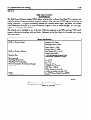
Thumbwheel Interface
IC6lOMDL105
This module provides an interface between the Series One or Series One Plus PCs and up to four sets of
user supplied thumbwheels.
Each set of thumbwheels will allow the operator to control the preset on a
timer or counter. In fact, these timer/counters (references 674 to 677) will not function without this
interface module. The power (24 V dc) to sense the state of these thumbwheels is provided by the
power supply in the CPU base unit. This interface module must be installed in the same base unit as the
CPU and can only be located in slots 2 through 5. Only one interface module is allowed per system.
The thumbwheels and their associated wiring must be supplied by the user. The thumbwheels are
standard BCD coded and diode isolated, a standard option available with most thumbwheels.
The
following is the required setting for each digit of the thumbwheel:
Digit
switch
4
Value
ClOSUXT?
2
(X=Closed)
1
0
X
1
2
3
4
5
6
7
8
9
X
X
X
X
X
X
X
X
X
X
X
X
Whenever the interface is installed in the CPU base unit, eight discrete references are assigned to this
module slot. These references have no significance relative to the operation of the interface. They can
be used as internal coils, but not as status to other hardware I/O. All four presets are read into the Series
One or Series One Plus PC each scan. Figure 6.39 illustrates the wiring for the 20 terminals on the
interface module. No special terminations are required for circuits that are not being used.
One thumbwheel
is read into the CPU every scan assuring rapid response to new values.
Care should be
used when changing the value on the thumbwheels, since intemW&te values can be brought in and used
during a scan or for several scans. For example, if the thumbwheel is set for the value 095 and the new
value 105 is desired, altering the hundreds digit first results in 195 being detected and used by the CPU,
until the tens digit is changed fkom 9 to 0. Normally, higher values are more acceptable than lower
values and the natural tendency to enter new values fkom the left or high order digit will result in larger
values. However, if the tens digit is changed first, the value 005 could be read prior to the 105 being set.
The exact results depend upon the application and the specific logic entered.
Intemal Power Consumption
9OmA@24Vdc(9unitsofload)
lOmA@ 9Vdc(l
mitofload)
I/O Specifications and Wiring
6-37
GEK-90842
.
,
.
.
.
.
.
.
.
.
.
.
.
COlvrvECwR
su)QufD
WlfH
INTERFACE
I
4L
THUMBWHEELS
SHOULD HAVE EACH MDlvIDuAL
SGkAL (E G. 800) DiODE ISOLATED AND 6uSSED TO WuTERFACE QG.
P!h 681 COUOwrrVC
TC(UMBWHEELS
’
SCb!EMATtCAUY
SHOWS GROUPS OF FOUR HDWOUAL
WINS FOR SMQLIClTY
TmuSAmS
L
COMMONS
-
WNDREDS
*
-
4675)
*
o-9
o-9
TENS
w
O-9
A
ATEACH
TrmMBWnEEL
UwTS
.m
a
es
N
DIODES
ARE TYPE
Iw 148. OR EQUAL
RECOMMENDED
AWGNO
23
WIRE
IN91 4.
SJZE IS
MAXIMUM
OfSTANCE TO FLJRTHEST
GROUP
OF THUMB-S
IS 10 FEET (3 METERS)
H -Y
-0
-MACE
EIwRONMENTS.
USE
WIRE GROUNDED Af
AN I’0 -ACE
CA&E
fm
t,#SEHmnMTSEL
IUTERFACf
is AVAILAbLE.
?MT~‘wn6tOC#~O5A
.
c
d
Figure 6-39. Wiring for Thumb wheel Interface
I/O Specifications and Wiring
GEK-90842
Thumbwheell-c8bbe
Wife List and Ifstallati0rr Diagram
I
Pm No.
I
W~cdaCUk
1
I
Bll
naaJnmcwd*
Bl2
notcxmmctw’
1
OFIN (eucsr
i
Figure 6-40. Thumbwheel Interface Cable Wire List
Gcu(Bu(3)
I
6-39
I/O Specifications and Wiring
GEK-90842
High Speed Counter
IC610MDLllO
The High Speed Counter module (HSC) allows a Series One or Series One Plus PC to monitor and
control a number of process variables (position, velocity, flow rate) that the CPU cannot control due to
timing constraints.
A logical relationship between the counters seven inputs, the preset, and current
value determines the status of its own two external outputs as well as others through CPU user logic.
Figure 6.41 illustrates this concept.
The module can be installed in any of the first 4 I/O slots adjacent to the CPU, and uses 8 I/O and 2
counter references to interface with user logic. Indicators on the front face of the module give output
and count status.
General
Increment (Up) Count
Decrement (Down) Count
Reset/Marker
PIeset value (0 - 9999)
Current Value (0 - 9999)
Two Discrae DC (5 - 24 V)
Current Value (BCD)
< 100 Microseconds Between Pulse
Received and Transition of Output
up/Down counter Inputs
up/DOWn
COMW
specifications
OUtpUtS
Reaction Time
Environmental
Operating Temperature
Humidity, Non-Condensing
Power Consumption from Internal Supply
Pulse Rate
we
Minimum Pulse Width
OFF-
0 to 6o” c
5 to 95 %
70mA@9Vdc
Without Filter < 10 Hz
With Filter < 500 Hz
(Filter selection by thee dip
switbes on module, see page 6-69)
0 to 9999 Binq bled Dhnal(BCD)
25 mS
I
+25@=4
6-41
I/O Specifications and Wiring
GEK-90842
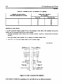
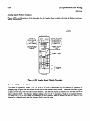
Module Location
The High Speed counter module (HSC) can be installed in any one of the four I/O slots adjacent to the
CPU slot in the CPU chassis. In figure 6.42, these slots are shown (A, B, C and D) for a 5-slot rack. In
a lo-slot rack, the HSC must also occupy 1 of the 4 slots adjacent to the CPU. Also shown in this figure
are the I/O references used by the HSC to intetiace with user logic. Note how an HSC located in Slot A
uses I/O references associated with both Slot A (O-3) and Slot A’ (100-103).
Since each slot in a Series One or Series One Plus PC I/O system corresponds to a special group of eight
I/O references, an HSC in Slot A eliminates Slot A’ from the I/O system. Likewise an HSC located in
Slot B eliminates Slot B’ from the I/O system. In summary, an HSC physically occupies one YO slot,
but requires two slots worth of I/o references to interface with user logic (Refer to table 6.5).
pc-sl -84-QOO 1
/ll-knIIlII
I
I
67
1
57
!
i
ONE
SERIES
47
F&we 6-42. HSC Location in 5-Slot Rack
6-42
I/O Specifications and Wiring
Table 6-5. Number of HSCs vs Discrete I/O Capacity
NUMBER OF HIGH SPEED
COUNTER MODULES IN SYSTEM
REMAINING DISCRETE
I/O CAPACITY
/
seriesone
I
Seri~OnePlUS
112
96
168
152
136
120
104
80
64
48
Interface to Field Devices
A 32 PIN Connector
(Refer to figure 6.43) on the faceplate of the HSC is the interface between the
module and its associated field devices which include:
1. Counting mechanism
encoder).
which controls the Up/Down
counter (typically
a bidirectional
2 . Four digit binary coded decimal (BCD) display of counters current value.
3 . Two 5 to -24 V dc loads under control of tvvo counter outputs.
Zoo0
@CD)-
c
1000
400
100
i-1
RESn
MARKER
BCD)
BCD)
@CD,
40
(BCDI
10
fBCD1
4
@CD)
1
MD)
(+I
(-1 SVDC 2 5- OR
12VDCZlD%
RESFf
(+I
MARKER
5 VDC = 5- OR
12VDCzlo;
1
(-1
DECREMENT
f-1
INCREMENT
COWTER
COWTER
i+b
DECREMENT
(+I INCREMENT
COUNTER
COUPTER
Figure 6143. HSC Connector Pin Definition
In the interestof claritythe specifications for each field device are addressed separately.
incremental
6-43
I/O Specifications and Wiring
GEIL90842
Up/Down Counter Inputs
SPECIF’ICATIONS
RESET INPUT
UP/DOWN INPUT
WEM
Minimum Input
Pulse ‘width
Supply Voltage
OnCuIrent
off Current
On Voltage
Off Voltage
25 nsec
loo nsec
+12 V dc, 10%
<3mA
10 to 15 IILA
<3Vdc
>7Vdc
+12 V dc, 10%
10 to 15 mA
<3mA
UVdc
<3Vdc
OFF r
a40068
I
I
.
.
ON--T
ON
,T
OFF 4
RESET*
COUNT*
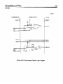
Figure 644. Signal Direction
The conditions necessary to increment/decrement,
particular interest when counting in one direction
or reset the counter are described below.
only.
DESIRED ACTION
Incxement Current Count
Decrement Cunent Count
Reset Chent
Count
Increment Input:
Decrement Input:
Reset Input:
CONDITION
Increment Input: (Disabled) - (Enabled)
Deuement Input: Disabled
Reset Input: Disabled
Decrement Inputz (Disabled) - (Knabled)
Increment Input: Disabled
Reset Input: Disabled
Reset Input (Disabled) -- (Enabled)
Increment Input: Disabled or Enabled
Decrement Input: Disabled or Enabled
Disabled,~10VdcBetweenPhsB1andAl
Enabled,<2VdcBetw~nPinsBl
andA1
Disabled,>lOVdcBetweenF5niB2andA2
Enabkd,<2VdcBetweenPinsB2andA2
Disabled,<2VdcBetweenPinsB6andA6
Enabled,~lOVdcBetweeaPinsB6andA6
Figure 6-45. UPlDOWNkESET
Input Circuit
.
This is of
644
I/O Specifications and Wiring
GEK-90842
Encoder Interface 1
Typically an incremental encoder controls the counter through the Up/Down, and Reset Inputs. To
comply with HSC circuitry, the encoder should represent clockwise and counterclockwise movement of
its shaft with two separate pulse trains that increment and decrement the counter. Figures 6.46, 6.47,
and 6.48 illustrate sample connections.
.’
pc-~1-84-0005
WGMSPEEDCou)JrrcI
MWULE
Figure
6-46. Encoder with RESET/MARKER Option
Resetting Counter Once Der Revolution
_
of Encoder Shaft
-
a
Figure 64% Encoder with RESET Option in Series with Home Limit Switch Such That
Counter is Reset When Both Home Limit Switch and RESET/MARKER Pulse
are Enabled
I/O Specifications and Wiring
6-45
GEL90842
PHOTO LLECTfBC CELL’
RESET
COUNTER
OECREMENT
COUNTER
HCREMENT
COUNTER
Figure 6-48. Encoder With Limit Switch Resetting Counter and Photoelectric Cell Inhibiting
the Counter Operation
L/O Specifications and Wiring
6-46
GEE90842
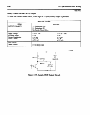
Binary Coded Decimal (BCD) Output
To view the counter current value, a four digit BCD (sink/source)
output is provided.
SPECIFICATIONS
RATING
ITEM
0uTPuTPoLARrN
SOURCE MODE
Supply Voltage
Allowable Ripple
cumnt CoI3sumption
Output Voltage
SINK MODE
Output Voltage
1: Optoisolator OFF
0: Ojmisolator ON
See Sample Circuit Below
12 V dc + 10%
< 3%
< 25 mA
6V&
at 0.4 mA
5Vdc
5%
< 1%
< 10 mA
3.5 v dc
at 0.1 mA
0.4 v dc @ 2 IIA
0.1 v dc @ 3 mA
a40070
SVDC
OR
r2vrlC
(SOURCE)
IOKfi
I
VOLTAGE
Figure 649. Sample BCD Output Circuit
I/O Specifications and Wiring
6-47
GEK-90842
Figure 6.50 illustrates the connections necessary to use an external BCD Display. For a source type
output the 5 V or 12 V supply is required.
SENSE OF OUTPUT:
SENSE OF OUTPUT:
(1) Optoisolator OFF
(0) Optoisolator ON
PCFOUR DIGIT
BCD DISPLAY
SAMPLE ClRCutT
I
t
OPTOISOLATOR
’
II
a
II
l-
V.
Figure 640.
5-12 VDC
BCD Output Wiring Diagram
UNITS
’
I/O Specifkations and Wiring
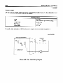
Counter Output
The HSC has two discrete outputs that can be controlled from ladder logic or by the relationship
between the present and current value of the counter.
SPECIFICATIONS
_
ITEM
RATING
Type
NPN Transistor, open collector, sinking
Voltage Range
Peak Voltage
Cumznt Range
5 to 24 V dc
< 45 V dc
> 0.3 A
A typical wiring schematic
to field devices and a sample circuit are shown in figure 6.51.
HK3H SPEED COUNTER MODULE
B
USER LOADS
+v
5-24VDC
Figure 641.
User Load Wiring Diagram
(>=<)
i-
I/O Specifications and Wiring
-c
6149
GEK-90842
Interface to User Logic
Eight I/O and two counter functions interface the HSC to user logic. The specificreferences associated
with these functions depend upon the location of the module in the CPU rack. Figure 6.52 illustrates
how these references comspond to the modules location.
I
1
’
couNTmfuwTmH
I
;
I
muNlm#RmNcm
I
I
I
I
;
,
’
,106I
PRESETVALUE
I107
' 105 , 103 I 101 I
,
,
’
I
’
mwr~~wcE8
I
I
I
I
m?urFwcrmu
I
I
>PRESETVALlE
’
‘30
-fRESOVMUE
I31
,
<PREsnvALlJE
' 32
CARRvmmRow
'I33
I
I
OvlcvTnmcnm
I
104,
t
smcuRRENTvALuf
I
‘20
omPulNO.l~SflECf'
omPuTMo.2sTATE
O~T~TNO.~M~~ESEECT'
'
’
I
I
’
1
I
I
1
1
22
,'2
IO2
,
, 23
113
I03
,
I
'
I
,
I
,
1
i
1130,
1
I
‘00
'01
I
ok!mAFElrmu,
I
100,
,‘O
(11
I2l
1
I
oiJlPul~.1S1AtE
102,
I
I
'
120,
110,
100;
131 I
132,
121,
122,
111,
112,
101 '
102 I
133'
123)
113'
103I
I
I
l
’
Figure 642. I/O and Counter Function Reference Chart
640
I/O Specifications and Wiring
Interface Function Definition
Shown below is the definition and user logic symbol for each interface function.
a42645
5
5
SET CURRENT VALUE
X+
v+
WHEN COUNTER X Is ENABLED,
CURRENT COUNT IS SET TO A
VALUE OF Y
O--r7
x: loo, 102,104,106
Y:O-9999
PRESET VALUE
4-l
CNT
X+
Y+
x: 101,103,105,107
Y:O-9999
l
l
X - Counter Reference
Y=VaMRarrge
WHEN COUNTER X IS ENABLED,
PRESET VALUE OF COUNTER
ISSETTOY
641
I/O Specificationsand Wiring
GEK-90842
a42646
PUT FUNCnQbls
> PRESET VALUE*
ENABLED WHEN CURRENT
VALUE OF COUNTER IS
GREATER THAN ITS PRESET VALUE
l
x: 00, 10,20,30
I: PRESET VALUE*
l
,1,
ENABLED WHEN CURRENT
VALUE OFCOUNTER IS
EQUAL TO ITS PRESET VALUE
x: 01, 11,21,31
ENABLED WHEN CURRENT
VALUE OF COUNTER IS
LESS THAN ITS PRESET VALUE
< PRESET VALUE+ *
X: 02, 12,22,32
CARRY / BORROW
,rt+
l
X: 03, 13,23,33
l
0001 - 0000 - 9999 (Decrement Rollover)
9999 - 0000 - 0001 (Increment Rollover)
0001 - 0000 - 0001
9998 - 9999 - 9998
(Increment Current Count) - (Extemalty Reset Counter) - (Decrement Current Count)
(Decrement Current Count) - (Externally Reset Counter) - (Increment or Decrement Current Count)
1.
2.
3.
4.
5.
6.
l
Enabied when current value of the counter undergoes one of the six sequences
described beiow :
l
The status of these input functions is given to the CPU once per scan. Therefore, if a
particularcanditbn is true for less than the scan time of the user bgic, its associated
Input function woukl not be enabled in the user program.
I/O Specifications and Wiring
GEK-90842
a42647
J
QEEMmQN’
USER
OUTPUT NO. 1
MODE SELECT
. IF DISABLED OUTPUT NO. 1
IS IN MANUAL MODE
. IF ENABLED OUTPUT NO. 1
IS IN COUNTER MODE
OUTPUT NO. 1
STATE
l
l
X: 103, 113, 123,133
. IF ENABLED OUTPUT NO. 2
IS IN COUNTER MODE.
l
,K,
X: 102,112, 122, 132
l
IN COUNTER MODE DETERMINES
IF OUTPUT NO. 1 IS ENABLED
BEFORE OR AmER PRESET
IS REACHED
. IF DISABLED OUTPUT NO. 2
IS IN MANUAL MODE
OUTPUT NO. 2
MODE SELECT
OUTPUT NO. 2
STATE
IN MANUAL MODE OPERATES
OUlWTNO. 1 AS
NORMAL OUTPUT
l
IN MANUAL MODE OPERATES
OUTPUT NO. 2 AS NORMAL
OUTPUT
IN COUNTER MODE DETERMINES
IF OUTPUT NO. 2 IS ENABLED
BEFORE OR ARER PRESET
IS REACHED
For further description on the operation of outputs, refer to Output Logic Section.
I/O Specifications and Wiring
643
GEK-90842
Ouptut Logic
Each of the two HSC outputs operate in either the manual or counter mode. The operating mode of each
output is determined by the state of its mode select function (refer to output function section). The logic
of each mode will be covered separately.
If Mode Select Function
Disabled (0): Manual Mode, Enabled (1): Counter Mode.
Manual Mode
The state of an output in the manual mode corresponds to the status of its associated
Function as shown below in the manual mode output truth table.
Output State
Table 6-6. Manual Mode Output Logic Truth Table
I
OUTPUT MODE SELECT
I
0
0
OUTPUT STATE
I
0
1
OUTPUT
I
0
1
l
Counter Mode
In the counter mode of operation outputs can react immediately when the current count reaches specific
preset values. In this mode each output is controlled by a combination of three ‘factors.
1. Initial relationship
between preset and current count.
2. Real time relationship
3. Status
of
between preset and current count.
Output State function.
When the HSC receives a preset value from user logic (via preset counter function), it is initially
compared to the current value of the counter. If the preset is-greater than the current count in this initial
comparison the real time comparison *2between the preset and current count is “true” when the current
count is greater than or equal to the preset. In other words when the current count reaches the preset
moving in the POSITIVE direction the real time comparison becomes “true”.
This concept is shown
below in table 6.7.
Table 6-7. Real Time Comparison Table for Preset Initially > Current Count
/
REAL TIME COMPARISON STATUS
CURRENT COUNT
< PRESET
CURRENT COUNT
-> PRESET
FALSE
TRUE
*Real Time compariston = continuous comparison between preset value and cummt value of cutmter.
1
6-54
I/O Specifkations and Wiring
GEK-90842
Conversely, if the preset is kGtially less than the current count, the real time comparison is “true” when
the current count is less than or equal to the preset. In other words, when the current count reaches the
preset moving in the negative direction the real time comparison becomes “true”.
This concept is
shown below in table 6.8.
Table 6-8. Real Time Comparison Table for Preset
Initially c Current Count
I
I REAL TIME COMPARISON STATUS
CURRENTCOUNT
> PRESET
FALSE
I
I
CURRENT COUNT
< PRESET
I
I
TRUE
I
Once the status of the real time comparison between the preset and current count has been determined,
the status of the output is easily obtained. If the outputs associated output state function is disabled its
status corresponds directly to the real time comparison status. If the output state function is enabled the
output’s status is the inverse of the real time comparison status. This concept is shown in table 6.9.
Table 6.9. Output State vs Real Time Comparison Status in Counter Mode
OUTPUT STATE
FUNCTION
I
I
DISABLED
ENABLED
1: OUTPUT ENABLED
0: OUTPUT DISABLED
Table 6.10 summarizes
I
I
I
REAL TIME COMPARISON
IS FALSE
0
1
REAL TIME COMPARISON
ISTRUE
I
1
0
-
I
the logic associated with an output in the counter mode of operation.
I
I
I
Ii0 Specifications and Wiring
6-55
GEK-90842
Table 640. Output Logic in Counter Mode
INITMLLY PRESET > CURREW
OUTPUT STATE FUNCTION
0
1
COUNT
cuRRENTcOuNT
< PRESET
0
CURRENT COUNT
> PRESET
1
1
0
INITMLLY PRESET < CURRENT COUNT
OUTFWT STATE FUNCTION
0
1
cuRRENTcOuNT
> PRESET
0
1
CURRENT COUNT
< PRESET
1
0
Filter Selection
In some electrical noisy environments it may be necessary to filter out noise through filters available on
the module.
The HSC provides this capability on the incremental count, decremental count, and
reset/inarker inputs. The location of these switches on the module is shown in figure 6.53.
Sense of switch: OPEN - Filter Disabled (< 10 Khz)
CLOSED - Filter Enabled (C 500 Hz)
Figure 643. Filter Selection with Dip Switch
II0 Specifications and Wiring
646
GEK-90842
Fast Response I/O
IC610MDL115
The Fast Response I/o module allows a Series One or Series One Plus PC to respond quickly to an
input and/or monitor very short input pulses. The module’s four 24 V dc inputs and two relay outputs
use 8 I/O references to interface with user logic. Each of the 2 outputs can operate in a manual or fast
response mode. An output in manual mode is controlled from user logic similar to any other discrete
output. An output in the fast response mode can be controlled independent of CPU scan time by its 2
associated inputs, with one input enabling it, and the other disabhg it. Up to 14 Fast Response I/O
modules can be included in a Series One or Series One Plus PC system, thereby providing 28 fast
response outputs and 56 inputs total. Following are specifications for each of the input and output
circuits.
r
DC INPUT CIRCUITS
Number of Circuits
Maximum Voltage (Open Circuit)
Input current
ON Level
OFF Level
OFF to ON Response
ON to OFF Response
Maximum OFF Cment
Minimum ON Current
Input Pulse Width
Chait Indicator
4
36 V dc
16 mA (maximum)
0-3Vdc
18 - 36 V dc
0.3 to 1 ms
50 to 150 ms
3mA
7mA
1 ms (minimum)
Field Side
NOTE
Input Switching Voltage Provided by Module
r
RELAY OUTPUT CIRCUITS
Number of Circub
Operating Voltage
2
S-265 V ac/dc
AC F’reqwncy
47-63 Hz
4 amp (esistive)
0.5 amp (inductive)
1mA
10 mA
Range
lkhuimum C-t*
Maximum Leakage Current
Smahst Recommended Load
Maximum Inrush
OFF To ON Response
ON To OFF Response
Ciralit Indicator
Ciralit Indicator
Fbse (In Output Common Line)
Wernal Power Consumption
5ms
5 ms (hum)
5 to 10 ms
Field Side
Field Side
3 mP
5OmA+53mA/OutputONChuitat9Vdc,
lS~ut@24Vdc
Units of Load: 16 (9 V dc)
6 (2A V dc)
Since non-solid state relays are used as the power switching devices, the limitations as shown in table
below must be observed for reliable operation.
I/O Specifications and Wiring
647
Table 641, Maximum Current vs. Load Type for Relay Outputs
OPERATING
MAXIMUM
I
VOLTAGE
22ovac
22ovac
1lOVac
11ovac
24 V dc
50 V de
1OOVdc
250 V dc
RESISTIVE
4bP
4bP
5bP
1hP
0.5
0.3
Amp
Amp
CURRENT FOR LOAD TYPE
LAMP
0.5 Amp
0.05
0.5
0.1
0.5
0.1
0.05
0.03
Amp
Amp
Amp
Amp
Amp
Amp
Amp
SOLENOID
1
TYPICAL
LIFE
(OPERATIONS)
100,ooo
800,000
150400
650,000
100,ooo
0.5 Amp
0.05 Amp
OJ Amp
0.1 Amp
0.5 Amp
0.1 Amp
0.05 Amp
0.03 Amp
100,000
100,ooo
100,ooo
NOTE
Lamp loads are defined as a X10 inrush with a power factor (PF) of 1.00 and when tumed OFF
represent a PF of 1.00. Solenoids are defined with a X10 inrush, a PF of 0.65, and when turned
OFF represent a PF of 0.35.
b40556
Figure
6-54. Module Reference NUMBER/LOGIC Symbol Definition
6-58
I/O Specifications and Wiring
GEK-90842
Mode Selection
The Operating Mode Selection of outputs X4 and X6 is determined
references SS and S7 as shown in table 6.12.
by the status of their mode select
Table 6-12. Operating Mode Selection
I
MODE SELECT
OUTPUT
I
(SS and S7)
Disabled (0)
Enabled (1)
I
w=dx6)
Manual Mode
Fast Response Mode
Output Logic - Manual Mode
An output operating in the manual mode is controlled through user logic similar to any other discrete
output. Its associated inputs on the fast response module do not affect it any way.
Output Logic - Fast Response Mode
In the fast response
output.
mode of operation,
a combination
l
State of Associated
Enable Input (Reference
l
State of Associated
User Logic
Disable Input (Reference
l
The truth table (following)
and disable inputs.
of three factors determines
the status of the
number 0 or 2)
number 1 or 3)
shows how the output can be controlled
from user logic or with its enable
Table 643. Truth Table for Output in Fast Response Mode
(S5 or S7 Have Been Enabled)
ENABLE INPUT
No. 0 or 2
DISABLE INPUT
No. 1 or 3
USER LOGIC
X4 or X6
OUTPUT
1
0
1
1
1
0
0
0
0
0
1
1
1
0
0
1
1
1
0
0
0
1
1
1
0
0
0
0
0: Disabled
1: Enabled
It can be seen from the first three rows in the truth table that the output can be enabled from its enable
input or from user logic. The last four rows of this truth table show the various conditions that disable
the outputs.
The logic diagram shown below in figure 6.55 summarizes the operation of this module.
I/O Specifications and Wiring
GEK-90842
a40547
CPU s&e (UserLogic)
Fast Response Moduk
fidd Side
Input No. 0 4
1 LnQutNo.0
hputNo.1
)
(
hputNo.1
b Output No. 4
Output No. 4 o(4) c
wect
Output No. 4 IS51 ’
hput No. 2 (I-
3 input No. 2
Input No. 3 (3-
3 Input No. 3 _
> OutputNo.
Output No. 6 DC61
SeIect
Output No. 6 @‘I)
Figure 645. Fast Response Module Logic Diagram
6-60
I/O Specifications and Wiring
G=-90842
USER WIRING
INPUTS
USER
MODULE
WIRING
OUTPUTS
c4
USER
WIRING
DIAGRAM
24 VDC
COMMON
r ___________~____+~’
I
I
I
I
I
I
I
I
I
L - ,d:P=
5 255
VAC DC
A
6
=
$
*
TO OTHER
m THREE CIRCUITS
INTERNAL
POWER SUPPLY
INPUT
H(-he
w -
A
A
v
w
LOAD
.> 5-265
I
RELAY
SAMPLE OUTPUT
3A
CIRCUIT
Figure 6-56. Wiring for Fast Response I/O Module
VAC’DC
6-61
II0 Specifications and Wiring
GEL90842
I/O Simulator
IC6lOMDL124
The I/O simulator module has 8 two-position
(ON or OFF) switches, each having an associated LED,
that is, if switch 1 is turned ON, LED 1 will light. An I/O simulator module uses one I/O slot and the 8
I/O references assigned to that slot. Each of the switches can be programmed as a discrete input device.
This module requires no field connections since its function is controlled by programming.
An I/O
simulator module is a valuable tool in program development and troubleshooting.
An I/O simulator
could also be programmed to be used as conditional input contacts for control of output devices.
Specifications for this module are as follows:
4 to 15 ms
4 to 15 ms
lOmA@ 9Vdc
14mA/CircuitON@24Vdc
lunit@9Vdc
llunits@24Vdc
3.2 oz (90 g)
ON to OFF Response
OFF to ON Response
Interndl
Power Consumption
unitsof Load
Weight
a40215
1
I
,
I
,
I/O SIMULATOR
Figure 647. I/O Simulator Module Faceplate
I/O Specifications and Wiring
6-62
GEK-90842
-.
Analog Input
IC610MDLll6
Introduction
The Analog Input module provides four independent
input channels capable of converting an analog
input signal to a digital signal for processing by the programmable controller. This module can be used
with Series One and Series One Plus programmable controllers.
However, the input can only be
provided in binary form with a Series One PC. ‘Ihe Series One Plus, in addition to the basic functions,
provides data operations (including math functions), which allows other types of operations to be
performed when using the analog input module. Each Analog Input module requires 16 I/O references
for addressing.
Hardware Features
The user can select, by jumper placement, to use either voltage inputs (1 to 5 V dc) or current inputs (4
to 20 mA>. The factory setting is for voltage input operation. Resolution is 8 bits, which allows a
maximum digital value of 255 to be converted. Eight LEDs on the faceplate provide an 8-bit binary
display of the input. The channel to be displayed is selected by depressing a pushbutton on the
faceplate. Each time the pushbutton is depressed, the next channel in sequence is selected, i.e., channel
1, 2, 3, 4, 1, etc.
User field wiring is made to a removable terminal board on the module’s faceplate. A hinged plastic
temG.nal cover on the terminal board protects the terminals. The terminal cover has a removable label
that can be used to record circuit information.
The maximum conversion time is 2 milliseconds and does not add to the scan time of the CPU. The
four channels are converted one at a time, with one channel being converted each scan. Each successive
scan converts the next channel in turn.
Power Requirements
This module requires an external 24 V dc power supply. The 24 V dc supply in Series One racks can be
used, however the current provided by the rack is limited to 100 mA, which is sufficient current for one
Analog Input module, sin& the module requires up to 65 m4 for operation.
General and Electrical Specifications
SpecifGzations for this module are provided
in the following table.
I/O Specifications and Wiring
6-63
GE&90842
Table 6-14. Analog Input Module Specifications
Number of cJhanmls
Input Ranges
(Independent)
+l to +5 v dc or 4 to 20 mA
(jumper selectable for each channel)
&bit binary (1 in 256)
8 bits, binary data output
4 bits, cbannel status
16 consecutive (per slot assignments for 16 points, 0 to 7 and 100 to 117, etc.)
8 bits: Data being read into the selected channel
4 bits: Channel selected for Data Display
4 bits: Channels being scanned
0 to 60’ C (32 to 140’ I?)
5% to 95% (non-condensing)
Differential
> 1 MSZ (Voltage put)
250 Sz (Current put)
Voltage Input, 0 to +lO V dc
Current Input, 0 to 30 mA
Successive Approximation Method
2 msec, maximum
fo.8%, maximum
21% at 25’ C, maximum
i50 ppm (parts per million) per l°C
+25 V dc, 65 mA (maximum)
55 mA (Supplied by rack power supply)
4
Resolution
Digital outputs
I/O Points Required
LEVI Display (16 LEDs)
Operating Temperature
Relative Humidity
@Jut Types
Input Impedance
Conversion Method
Conversion Time
Linearity Error
AmY
Accuracy vs. Temperature
External Power Source
9 V dc Power Consumption
I/O Reference Definitions
The Analog Input module uses 16 consecutiveI/O points, beginning with the first I/O reference assigned
to the I/O slot selected for the module. In the table, it is assumed that the Analog Input module is placed
in slot 3 of a properly configured 5 or lO-slot CPU rack (references 10 to 17 and 110 to 117). These
references are used for the example only, other valid references for I/O slots that allow 16 references can
be used. The following table defines the use of each of the I/O points.
Table 6-15. I/O Point Definition
I/O POINT
10
11
12
13
14
15
16
17
110
111
112
DEFINITION
Data Bit - Binary
Data Bit - Binary
Data Bit - Binary
Data Bit - Binary
Data Bit - Binary
Data Bit - Binary
Data Bit - Binary
Data Bit - Binary
Channel 1 ‘Ibis bit is used in ladder logic to sense
whenthedatarezeivedattheinputsisforthis
channel.
Channel 2 sense bit
-1
3 Sense bit
WEIGHT
1
2
4
8
16
32
64
128
I/O TYPE
Input
Input
Input
Input
Input
Input
Input
Input
Input
Input
Wut
I/O Specifkations and Wiring
644
GEK-90842
Table 645. I/O Point Definition - Continued
I/O POINT
WEIGHT
DEFINITION
113
114
115
Channel 4 Sense bit
This output combined with the following output can
be set to selectively scan only 1 channel, instead of all
4. These outputs are ignored if the scan selection
output is on. The desired channel is selected by
settingthesetwooutputsinthel~logictothe
state, as shown below, for that channel.
OUTPUT 114
0
OUTPUT 115
0
1
0
0
1
1
1
116
117
Not used
Scan selection output. This bit must be set for the
module to n5ad data input, unless the selected channel
scan outputs anz used. This output is set in the ladder
logic program
I/O TYPE
Input
output
-put
1
2
3
4
output
Sample Ladder Logic
Sample ladder diagrams are provided below using the same I/O referencing as is used in defking the I/O
points in Table 6.15 on the previous page. These are examples of programming the Series One Plus.
Example 1. If all channels are to be scanned, output 117 must be on.
I
117
SW1
+ -m-- 1 I ~~-~~~~~~~~~~~~~~~~~~~~~~~~~~~~~
( s )--+
117
E~~~~~~~~~~~~~~~~~~~~~
(
R
)
--&
I
SW1 and SW2 are
switches
user
I/O Specifications
and Wiring
6-65
GEK-90842
Example 2. This example of ladder logic allows you to select the channel to be scanned.
1 CH
2 SELECT
114
&___]
I
CH 4 SELECT
+ ---1 1
----I)--
CH 3 SELECT
+ ---1
+
111-w
+
w--w
115
CH 4 SELECT
1 1
-----1-
SW2
+ ----
I
[ ~~--~~~~~~-~~
I
1~-~~~~---~~~~~~~-~~~[
+ ----[
F51 R# 1
]-------+
F60 R# 500]-------+
Retrieve data
and
convert to BCD
Store channel 1 data in
registers
500 and 501
111
+
w---
+
--I)-
+
-m-w
I
[ ~~~~---------~~~~~~~[
112
-~~~~~~~---~-~~~~~~~[
I
[
g-60
R#
5()2]---_---
Store channel 2 data in
registers 502 and 503
F60 R# 5041.-0-0-0 +
Store channel 3 data in
registers 504 and 505
~'60 R# 50610-0---9+
Store channel 4 data in
registers 506 and 507
113
I
[ ~~--~~----~---~~~-~~[
The Function codes used in the above example are as follows:
F51 = D STRl (Data Store l), F86 = BIN to BCD, F60 = D OUT (Data Out)
I/O Specifications and Wiring
6-66
GEK-90842
Analog Input Module Features
Figure 6.58 is an illustration of the faceplate for the Analog Input module, showing its features and user
wiring CoMections.
a41 896
CHANNELS
BEINGSCANNEDALL DIM,
IF ALLSCANNED
1
DATABEINGREAD
IN ON SELECTED CHANNEL
31 31
CHANNELSELECTED
FOR DATADISPLAY
BY DEPRESSING
PUSHBUTTON
1
I4164
FOR
-DATADISPLAY
&
+
CHANNEL I INPUT
+24V
ov
EXTERNAL
SUPPLY
Figure 648. Analog Input Module Faceplate
Sekction Of Operating Mode
The mode of operation, either 1 to 5 V or 4 to 20 IYA is determined by the absence or presence of
jumper plugs on pins that are located on the side of the bottom circuit board. There are four sets of pins
(2 pins in each set), with one set for each channel. The first set of pins is labeled CHl and the last set of
pins is labeled CH4. The factory default setting is for 1 to 5 V operation, which is no jumper present.
TO select the 4 to 20 mA mode of operation for any channel, place a jumper on the two pins for the
channel or channels and push the jumper fkmly onto the pins.
I/O Specifications and Wiring
6-67
GEL90842
Analog Output
IC610MDL166
Introduction
The Analog Output module provides two independent output channels, each capable of converting 8 bits
of binary data to an analog output. ‘This module can be used with any of the Series One family of
programmable
controllers. The Series One Plus, in addition to the basic functions, provides data
operations (including math functions), which allows other types of operations to be performed when
using the analog output module. Each Analog Output module requires 16 YO references for addressing.
Although this module can be used with the Series One and Series One Junior, in addition to the Series
One Plus, certain programmin g techniques will make better use of the capabilities of the Analog Output
module with these PCs. An APPLICATION NOTE will be issued explaining those techniques in detail.
Hardware Features
Each channel can provide either a voltage output (0 to +lO V dc) or current output (4 to 20 r&4 source).
Voltage or current selection for each channel is user selected by how the field wiring is connected on the
scow terminals on the faceplate. Resolution is 8 bits, which allows a maximum digital value of 255 to
be converted. Eight LEDs for each channel on the faceplate provide an 8-bit binary display of the data
output for each channel.
User field wiring is made to a removable terminal board on the module’s faceplate. A hinged plastic
terminal cover on the terminal board protects the terminals. The terminal cover has a removable
label
that can be used to record circuit information.
The maximum conversion time is 10 microseconds
channels are converted with each scan.
and does not add to the scan time of the CPU. Both
Power Requirements
This module requires an external 24 V dc power supply. The 24 V dc supply in Series One racks can be
used, however the current provided by the rack is 100 mA, which is sufficient current for one Analog
Output channel, since the module requires up to 85 mA for operation.
The maximum load for both
channels is 170 m4.
General and Electrical Specifications
Specifications
for this module are provided
in the following table.
6-68
II0 Specifications
and Wiring
GEL90842
Table 6-16. Analog Output Module
Number of Channels
Analog Output Ranges
Resolution
Digital Input Data
I/O Points Required
2 (Independent)
. 0 to +lO V dc or 4 to 20 mA
(selectable for each channel on faceplate terminals)
&bit binary (1 in 256)
8 bits, binary from the CPU
16 consecutive (per slot assignments for 16 points, 0 to 7
and 100 to 117, etc.)
8-bit binary data display of output data for each channel
.
.
LED Display (16 LEDs)
8 LEDs for each channel
Operating Temperature
Relative Humidity
Output Impedance
Output Current
External Resistor
Conversion Start
Conversion Time
Accuracy
Accuracy vs. Temperature
External Power Source
9 V dc Power Consumption
I/O Reference
Specifications
0 to 60’ C (32 to 140’ F’)
5% to 95% (non-condensing)
< 0.5L (Voltage Output)
10 mA, maximum (Voltage Output)
55OL, maximum (Current Output)
At start of CPU’s scan
10 msec, maximum
0.2% at 25OC
30 ppm (parts per million) per l°C
+24 V dc, 85 mA (maximum)
55 mA (Supplied by rack power supply)
Definitions
The Analog Output module uses 16 consecutive I/O points, beginning with the first I/O reference
assigned to the I/O slot selected for the module. In the table, it is assumed that the Analog Output
module is placed in slot 2 of a properly configured 5 or lO-slot CPU rack (references 0 to 10 and 100 to
110). These references are used for the example only, other valid references for II0 slots Jhatallow 16
references can be used.The following table defines the use of each of the I/O points.
Table 6-17. I/O Point Definition
I/O POINT
CHANNEL
0
1
2
3
4
5
6
7
100
101
102 ,
103
104
105
106
107
DEFINITION
DATA
Channel
Channel
Channel
Channel
Channel
Channel
Channel
Channel
Channel
Channel
Channel
Channel
Channel
Channel
Channel
Channel
WEIGHT
1 - Data Bit 1
1 - Data Bit 2
1 - Data Bit 3
l- Data
1 - Data
1- Data
1- Data
1 - Data
2- Data
2 - Data
2 - Data
2- Data
2- Data
2- Data
2 - Data
2- Data
L/O TYPE
Bit
Bit
Bit
Bit
Bit
Bit
Bit
Bit
Bit
Bit
Bit
Bit
Bit
4
5
6
7
8
1
2
3
4
5
6
7
8
1
2
4
8
16
32
64
128
1
2
4
8
16
32
64
128
output
output
output
output
output
output
output
output
output
output
output
output
output
output
output
output
6-69
I/O Specifications and Wiring
GE&90842
Sample Ladder Logic
A sample ladder diagram is provided below showing a method of how to move output data to Channels
1 and 2. This is an example of programming the Series One Plus for using the Analog Output module.
Example.
Move output data to Channels 1 and 2, using the same I/O references as are used in
previous table; i.e., 0 to 7 for Channel 1 and 100 to 107 for Channel 2.
SW1
SW2
+ --w-1 [----I/[-w---w
SW1
+ m--w IO ---I,
----a-[
1 -------
------
1 F85
-----[
F61
----111[
~50 R# 502]-------+
R#
0
+
]-------+
SW2
1 111-----
-----[
The
F50
F85
F61
F50 R# 500]-------+
F61
R#
10
I-------
Function codes used in the above example are as follows:
= D STR (Data Store)
= BCD to BIN
= D OUT1 (Data Out 1)
Move data from
registers
500/501
to the accumulator
then
Convert data from
BDC to Binary
and
Send the data to
Channel 1
Move data from
registers
502/503
to the accumulator
then
Convert data from
BCD to Binary
and
Send the data to
Channel 2
-
6-70
I/O Specifications and Wiring
GEK-90842
Analog Output Module Features
Figure 6.59 is an illustration
user wiring connections.
of the faceplate for the Analog Output module,
a41 897
CHANNEL I
DISPLAY OF
DATAOUTPUT
CHANNEL I
4T0 20MA
OUTPUT
OR
CHANNEL I
0 TO +lOV
OUTPUT
CONNECTIONSON
MODULE,ONLY
ONEREQUIRED
SUPPLY
Figure 6-59. Analog Output Module Faceplate
showing its features and
I/O Specifications and Wiring
6-71
GE&90842
UL Listed Products
The Series One products that have obtained UL approval or are UL pending are described in the
following pages. These products are listed below. As with all products that have obtained UL approval,
each listed item has an attached UL label.
l
IC61OCPUlOl
Series One CPU. Version C of the CPU is UL Listed. The functionality
has not changed, all specifications are the same as the previous version.
l
IC61OCHSlll
l
IC61OMDL135
Series One 115 V ac Input module,
l
IC61OMDLl81
IC61OMDLl85
Series One Relay Output module, 5 circuits.
Series One 115 V ac Output module, 6 circuits.
l
Series One S-slot rack.
of the CPU
115 V ac source of input power required.
The following pages contain the technical specifications
the Series One UL listed products.
6 circuits.
and wiring information
required to implement
II0 Specifications and Wiring
6-72
GEK-90842
5-Slot Rack, UL Listed
IC610CHSlll
The 5-slot UL Listed rack is similar to the existing 5-slot rack, IC610CHS110, in that it has a power
supply to the right and slots to contain up to 5 modules. The power supply for this UL rack requires an
input power source of 115 V ac. This rack does not accept 230 V ac input.
As with existing S-slot rack, a terminal board is provided for field wiring connections, refer to the
following figure. The two top terminals a for the 115 V ac HOT (H) and NEUTRAL (N) connections.
The next two terminals are for connecting an external device to the RUN relay, the next two contacts (+
and -) provide a 24 V dc output voltage at 100 mA for connection to an external sensor, and the bottom
terminal is the common (C) connection to an expansion rack.
When used as the first rack in an installation, it must contain the CPU which is placed in the slot next to
the power supply. The rack can also be used as the second or third rack in a system if more I/O is
required than can be contained in the first rack. A two-position switch on the inside, left of the rack,
must be set detetied
by location of the rack in the system. For a UL approved installation, do not mix
UL approved and non UL racks or modules. Specifications for this rack are as follows:
AC power
Requeucy:
Required:
Maximum Load:
output current:
115vac,
15%
47 to 63 Hz
0.8 A, max.
1.4 A, at 5 V dc
0.8 A, at 9 V dc
0.5 A, at 24 V dc
b41930
Figure 6-60, UL Listed SISlot Rack
II0 Specifications and Wiring
6-73
GEK-90842
115 V ac Input Module, UL Listed
IC6lOMDL135
This UL listed module provides 6 circuits, each designed to receive a single discrete (ON or OFF) signal
from user supplied devices. Examples of these devices include limit switches, pushbuttons, selector
switches, and relay contacts. The 6 circuits are grouped together and share a single common terminal.
Power to operate the field devices must be supplied by the user. An LED, viewed on the faceplate,
provides a visible indication of the ON or OFF state of each circuit. Specifications for each of the 6
circuits are Drovided below:
Input Points
Operating Voltage
AC Frequency
Input Current
6
97 to 132 V ac
47 t 63 Hz
7mAperpoint
maximum
9.5 K ohms
>8OVac
<2ovac
10 to 30 ms
10 to 60 ms
Field Side
lOmAat9Vdc
1 unit (9 v dc)
Input Impedance
ON Level
OFF Level
OF'F to Oh’ Response
ON to OFF Response
Circuit Indicator
Internal Power CoIlsumption
Units of Load
a41 924
USER
WIRING
MODULE
TYPICAL
REFERENCES
a41 687
r_w-‘&___
t
I
I
I
‘I
1
‘15VAC
COMMON
L _J&_-_
4-J
TO OTHER
CIRCUITS
OPTICAL
COUPLER
Figure 6-61. Wiring for UL Listed 115 V ac Input Module
634
I/O Specifications and Wiring
GEK-90842
Relay Output Module, UL Listed
IC610MDL181
This UL listed module provides 5 circuits, each capable of controlling
user supplied discrete (ON or
OFF) loads. These loads typically include relay coils, motor starters, solenoid valves, annunciation
devices and indicator lights. Since this module is not designed to operate with a specific cumnt type
such as 115 V ac or 24 V dc. It can be used to control a wide variety of loads and signal types. The
relay contact rating for this module is ClSO.
The 5 circuits are arranged in one group, with 2 common connections, which are tied together internally.
Power to operate the field devices must be supplied by the user. An LED, viewed on the faceplate,
Drovides a visible indication of the ON or OFF state of each circuit.
a41 925
outputs
Operating Vokage
AC F’requency
Contact Rating
CwTenty Continuous
Current, Make, 120 V
Current, Break, 120 V
M&mum
Leakage Current
(across contacts)
Smallest Recommended Luad
Maximum Inrush
OFF to ON Response
ON to OFF Response
Chuit Indicator
Fuses (Internal)
Internal Power Consumption
Units of Load
5
5 to 132 V ac/&
4’7 to 63 Hz
Cl50
2.5 Amps
15 Amps
1.5 Amps
1 mA
TYPICAL
REFERENCES
MODULE
USER
WWNG
030
031
032
5 mA
5 amps
5 ms
4 ms
Logic Side
(1) 10 amp, replaceable
45 mA for each ON
circuitat9vdc
23Unitsat9Vdc
TO OTHER
CIRCUITS
033
034
INTERNAL
JUMPER
a41 689
COMMON
____&‘p___q
\/
I
I
I
I
I
I
COMMON
I
I
I
Figure 6-62. Wiring for UL Listed Relay Output Module
II0 Specifications and Wiring
6-75
GEK-90842
115 V ac Output Module, UL Listed
IC610MDLl85
This UL listed module provides 6 circuits, each capable of controlling
user supplied discrete (ON or
OFF) loads. These loads typically include relay coils, motor starters, solenoid valves, annunciation
devices and indicator lights.
The 6 circuits are arranged in two groups, with a single common
connection for all circuits. Power to operate the field devices must be supplied by the user. An LED,
viewed on the faceplate, provides a visible indication of the ON or OFF state of each circuit.
1 CAUTION
1
If this module is wired incorrectly or the listed specifications are exceeded, any damage
incurred by the module may not be covered by warranty.
outputs
Operating Voltage
AC Frequenizy
Maximum Current
Maximum Leakage Current
ON Voltage Drop
Smallest Recommended
Maximum Inrush
Load
OFF to ON Response
ON to OFF Response
Circuit Indicator
Fuses (Internal, soldered)
Internal Power Consumption
Units
of Load
6
97 to 132 V ac
47 to 63 Hz
0.5 amp (per patint)
0.5 mA al 110 v ac, 60
Hz
0.8 V dc at 0.5 SIIP
25mA
10 ampsfor
/ 5 =ps for
a41 926
TYPICAL
REFERENCES
MODULE
USER
WIRING
040
041
16 ms
100 ms
042
I lms
~ 8 to 10 ms (l/2 cycle)
043
1 Logic Sick
(2) 5 =p
(one for each efoup uf
thrte circuits)
20mAforeachON
d5rcuitat9vcic
l2unitsat9vcic
044
045
a41 688
TO OTHER
3 CIRCUITS
--+h
HOT
97 132
r4 VAC
Figure 6-63. Wiring for UL Listed ll!W ac Output Module
I/O Specifkation~ and Wiring
6-76
115 V ac Input Module (16 Circuits
With Removable Terminal Board
IC610MDL129
This module provides 16 circuits each designed to receive a single discrete (ON/OFF) signal from user
supplied devices. Typical input devices include limit switches, pushbuttons, selector switches, and relay
contacts. The 16 circuits are divided into two groups of 8 circuits each. Each group can be supplied
from a separate power source. Power to operate the field devices must also be supplied by the user.
Figure 6-64 provides wiring information for this module. Following are specifications for each of the 16
circuits.
a42493
Input Points
OpeWing Vohage
AC Frequency
Input Current
Intescon.nection
ON Level
OFF Level
OFF to ON Response
ON to OFF Response
Circuit Indhtor
Internal Power Consumption
Units of Load
weight
l2
OF
-6ON
4
N
10%
Figure
WlRtNG
115VA
A
11
a42308
I
-
FIELD
16
80-132 V ac
47-63 Hz
14Sma @ 60 Hz
2 groups of 8 circuits
each
Above 80 V
Below 15 V
S-50 ms
5-60 ms
Logic Side
~~@9VwqqQ
1ounits@9vcic
6.4 02 (180 g)
MODULE
644.
20%
30%
40%
50%
,.rrrwTTEwERAfll#~)
60%
I/O Points vs Temperature
Chart
a42362
Fiire
6-65. Wiring for 115 V ac Inputs with Removable Terminal Board
.
II0 Specifications and Wiring
6-77
GEK-90842
115/230 V ac Output Module (8 Circuits)
with Removable Terminal Board
ICXlOMDL179
This module provides 8 circuits each capable of controlling user supplied discrete (ON/OFF) loads.
Typical loads include relay coils, motor starters (up to No. 3), solenoid valves and indicator lights. The
8 circuits &IS divided into 2 groups of 4 circuits each. Each group can be supplied from a separate
power source. Power to operate the field devices must also by supplied by the user. Figure 6-65
provides wiring information for this module. Followinn are sDecifications for each of the 8 circuits:
Y
output Points
Operating Voltage
AC F’rquency
lkhximum Current
Maximum Wage
Curreut
011’ Vdtage Drop
SmaIlest Recommended
Load
*urn
Inrush
OFF to Oh’ Response
011’ to OFF Response
Circuit Indicator
Fuses (Interual, Soldered)
Iutemal
Power Consumption
Units of Laad
weight
A
8
80-264 v ac
47-63 Hz
a42492
MODULE
1 -P
1.2 mA @ 23ov, 60 Hz
1.w @ 1 amp
25 ti
10 amps for 17 ms
1 ms
9 ms
Logic Side
(2) 5 amp (one on each
group of 4)
12 mA for each ON
circuit@9vdc
16@9Vdc
7.4 02 (210 g)
USER WIRING
l-4
’
l
co
*
6
a42367
7
8
NJl#o
OF:
-.
H
6-W
1.0 AWPOINT
a4
Figure 6-66. I/O Points vs Temperature
Chart
a42366
Figure 6-67. Wiring for 115/230 V ac Output with Removable Terminal Board