1
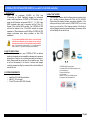
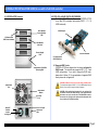
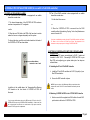
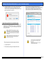
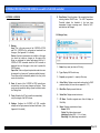
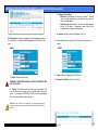
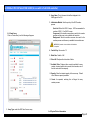
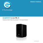
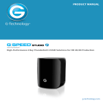
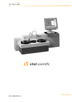
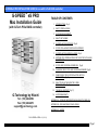
G-SPEED eS PRO INSTALLATION GUIDE (for use with G-Tech RAID controller)
GUIDE Guide
G-SPEED™ eS PRO
Mac Installation Guide
(with G-Tech PCIe RAID controller)
G-Technology by Hitachi
Tel: (310) 449-4599
Fax: (310) 449-4670
[email protected]
TABLE OF CONTENTS
1.
INTRODUCTION (Pg 4)
2.
SAFETY PRECAUTIONS
3.
SYSTEM REQUIREMENTS
4.
WHAT’S IN THE BOX
5.
G-SPEED eS PRO OVERVIEW (Pg 5)
6.
G-TECH PCIe x8 RAID CONTOLLER OVERVIEW
7.
G-SPEED eS PRO AUDIBLE ALARMS (Pg 6)
8.
SETTING UP G-SPEED eS PRO WITH THE G-TECH PCIe RAID
CONTROLLER
9.
G-TECH RAID CONTROLLER WEB GUI (Pg 8)
10.
CHANGING THE G-TECH RAID CONTROLLER MODE (Pg 9)
11.
CONFIGURING TWO G-SPEED eS PRO UNITS IN
RAID 5 MODE (Pg 11)
12.
WHAT TO DO IN THE EVENT OF A DISK
DRIVE FAILURE (Pg 15)
13.
TECHNICAL SUPPORT (Pg 17)
14.
LIMITED WARRANTY
APPENDIX A – DETAILED INFORMATION ON USING THE WEB GUI
APPENDIX B – EXPLANATION OF RAID LEVELS
APPENDIX C – NOTES
P/N G-SPEED eS PRO v1.2 (11/11)
Page 1
G-SPEED eS PRO INSTALLATION GUIDE (for use with G-Tech RAID controller)
GUIDE Guide
Page 2
G-SPEED eS PRO INSTALLATION GUIDE (for use with G-Tech RAID controller)
GUIDE Guide
Page 3
G-SPEED eS PRO INSTALLATION GUIDE (for use with G-Tech RAID controller)
GUIDE Guide
1. INTRODUCTION
Thank
you
for
purchasing
G-SPEED
eS
PRO
from
G-Technology by Hitachi! Specifically designed for professional
content creation applications, G-SPEED eS PRO features a highspeed mini-SAS interface and provides RAID 0, 1, 3, 5, RAID 6 and
JBOD functionality when used in conjunction with the G-Tech PCI
Express (PCIe) mini-SAS RAID controller. Two G-SPEED eS PRO
units can be attached to the G-Tech RAID controller for storage
capacities to 8 TB and data rates over 600 MB/sec. G-SPEED eS PRO
supports multi-stream video editing workflows on Mac PRO
workstations.
4. WHAT’S IN THE BOX
Take a moment to ensure that the following items are included in the
box. If anything is missing, please call G-Tech at (310) 449-4599.
Please keep the shipping container and packing materials. In the
unlikely event that you need to return G-SPEED eS PRO to us for any
reason, you must use the G-Tech shipping container. If the Product is
returned damaged caused by improper packaging, the warranty will be
void and liability will rest with the user.
If you purchased G-SPEED eS PRO with the G-Tech PCIe RAID
controller before November 2011, the system has been set up at
the factory for use with the G-Tech PCIe RAID controller in RAID 0
mode. The controller also supports RAID 1, 3, 5, 6 and JBOD modes.
Refer to Section 10 if you wish to change the mode of operation.
2. SAFETY PRECAUTIONS
The disk drives contained in your G-SPEED eS PRO are delicate
electronic instruments and are susceptible to damage due to excessive
physical shock. Place the unit in a vented area away from moisture or
liquids. Please handle the unit with care. Do not open the case. Doing
so will void the warranty. If the Product is returned with damage
caused by improper handling, the warranty will be void and liability will
rest with the user.
3. SYSTEM REQUIREMENTS
•
•
•
Apple Mac PRO (Intel Mac) workstation
Mac OS X 10.4.x or higher
G-Tech PCIe x8 mini-SAS RAID Controller
• G-SPEED eS PRO storage system
• 4 removable SATA drive modules (installed in unit)
• (2) disk module keys
• 2-meter mini-SAS cable
• AC Power cable
• Optional – G-Tech PCIe x8 RAID controller
• Configuration Utility & Installation CD
Page 4
G-SPEED eS PRO INSTALLATION GUIDE (for use with G-Tech RAID controller)
GUIDE Guide
6. G-TECH PCIe x8 RAID CONTOLLER OVERVIEW
The G-Tech PCIe RAID controller connects G-SPEED eS PRO
to any Mac PRO workstation and provides RAID 0, 1, 3, 6 &
JBOD functionality.
5. G-SPEED eS PRO Overview
(4) Removable
Disk Drive Modules
Drive Module
Power/Activity
LED
RAID Engine
Disk Module
Lock Hole
Power Supply
LED
PCIe x8 interface
(2) High-speed
mini-SAS ports
Temperature/Fan RPM
Warning LED
G-SPEED eS PRO has been set up at the factory in RAID 0 mode.
The controller also supports RAID 1, 3, 5, 6 and JBOD modes. Refer to
Section 10 if you wish to change the mode of operation.
Removable
Fan
Alarm Mute
Button
mini-SAS
Port
ON/ OFF
Switch
“smart”
cooling fan
6.1 Supported RAID Levels
G-SPEED eS PRO was shipped from the factory configured in
RAID 0 mode. The controller also supports RAID 1, 3, 5, 6 and
JBOD configurations. If you wish to change the RAID mode,
please refer to Section 10. For an explanation of supported RAID
levels, please refer to Appendix B.
G-SPEED eS Pro sold before November 2011 are configured for
use with the G-Tech PCIe RAID controller. Units purchased after
this date are set up for use with the ATTO R680 RAID controller.
See section 10 to configure units purchased after November 2001
for use with the G-Tech RAID controller.
AC Input
Cable Lock
Hole
Page 5
G-SPEED eS PRO INSTALLATION GUIDE (for use with G-Tech RAID controller)
GUIDE Guide
7. G-SPEED eS PRO AUDIBLE ALARMS
7.1 The G-SPEED eS PRO enclosure is equipped with an audible
alarm that sounds when:
7.2 The G-Tech RAID controller is also equipped with an audible
alarm that sounds when:
1. A disk drive failure occurs
1. The internal temperature of the G-SPEED eS PRO enclosure
reaches a temperature of 60° centigrade
or
2. When the G-SPEED eS PRO is removed from the RAID
controller without first selecting “Unplug” in the Array Maintenance
menu in the web GUI.
and/or
2. When the main FAN fails or the RPM of the fan slows to a state
where the fan can no longer adequately cool the system.
If you hear an audible alarm coming from the G-Tech RAID controller, see Section
12 “What to do in the Event of a Disk Drive Failure”. See Appendix A.2 for
information on the proper way to hot “Unplug” G-SPEED eS PRO.
To silence the alarm, push the mute button located on the back of
the G-SPEED eS PRO as shown below
Mute Button
located on rear of unit
8. SETTING UP G-SPEED eS PRO WITH THE G-TECH PCIe RAID
CONTROLLER
G-SPEED eS PRO comes pre-configured in RAID 0 mode and
formatted for MAC OS X. Connecting G-SPEED eS PRO to your
Mac PRO and configuring your system takes just a few steps as
outlined below.
8.1 Installing the G-Tech PCIe RAID Controller
In addition to the audible alarm, the Temperature/Fan Warning
LED located on the front bezel of G-SPEED eS PRO will
illuminate.
1.
Install the G-Tech RAID controller into SLOT 4 (top slot) of your
Mac PRO workstation.
2.
Secure the RAID controller in place.
NOTE: If you are using an AJA, Blackmagic Design or equivalent video
capture card, install it in SLOT 3 unless otherwise instructed by the card
vendor.
8.2 Attaching G-SPEED eS PRO to the G-TECH RAID Controller
1.
If you hear an audible alarm and see the RED warning LED on the front of GSPEED eS PRO, stop using G-SPEED eS PRO immediately. Check to see if the
fan is spinning and move the unit to a cooler location. If you require a new fan,
contact G-Tech Support for a replacement.
Attach one end of the supplied mini-SAS cable to the mini-SAS
port located on the back of G-SPEED eS PRO.
Page 6
G-SPEED eS PRO INSTALLATION GUIDE (for use with G-Tech RAID controller)
GUIDE Guide
2.
Attach the other end of the mini-SAS cable to Port 1 (leftmost port)
on the G-Tech RAID controller as shown below.
2. Double-click on the “G-Tech RAID Controller” installer package as
shown below.
PORT 1
3.
Attach the power cord to the back of G-SPEED eS PRO and
connect the other end to AC power.
4.
Power on G-SPEED eS PRO.
3. The following window will appear. Follow the
instructions to load the software.
8.3 Loading the G-Tech PCIe RAID Controller Software
Check for software updates at http://www.g-technology.com/Support/
If you are upgrading software you must un-install the previous version first.
See section 8.4 for details
1. Double-click on the G-SPEED eS PRO icon located in the
“Manuals-Drivers” folder on the included CD as shown below.
Page 7
G-SPEED eS PRO INSTALLATION GUIDE (for use with G-Tech RAID controller)
GUIDE Guide
4. After restarting your system, the G-SPEED eS PRO will
mount on your desktop.
Your G-SPEED eS PRO is shipped from the factory in RAID 0 mode.
The G-Tech RAID controller also supports RAID 1, 3, 5, 6 and JBOD
modes. Refer to Section 10 below if you wish to change the mode of
operation.
NOTE: A shortcut has been provided to access the web GUI. Drag the “G-SPEED
eS PRO Web GUI” file (located in the folder Manuals-Drivers\G-SPEED eS
Pro\Shortcut to Web GUI) to your Documents folder. Drag the file from the
Documents folder to the dock as shown below. Click on the icon to access the
web GUI.
8.4 Uninstalling the G-Tech PCIe RAID Controller Software
1. Double-click on the uninstall.command file located in the
“Manuals-Drivers/G-SPEED es Proz” folder on the included CD as
shown above.
2. A Terminal window will open and you may be prompted to
enter your password to delete the installed driver
and web GUI.
Note:
See appendix A.4.5 for instructions on changing
password
2. The following will appear in your browser window. Enter
“admin” as the User Name and “0000” (four zeros) as the
Password and click on the <Login> button.
9. G-TECH RAID CONTROLLER WEB GUI
The G-Tech RAID controller web GUI is used to configure and monitor
the G-SPEED eS PRO system. The GUI is accessed using any web
browser such as Safari, Internet Explorer or equivalent.
9.1 Accessing the G-Tech PCIe RAID Controller Web GUI
1. Open your web browser and enter the following address:
http://localhost:7412
Note: See appendix A.4.5 for instructions on changing
the password
Page 8
G-SPEED eS PRO INSTALLATION GUIDE (for use with G-Tech RAID controller)
GUIDE Guide
3. The main screen of the web GUI will appear as shown below. Note
that the G-SPEED eS PRO is set up as a RAID 0. Each of the four
drives in the unit are displayed in the lower Section of the GUI.
10.1 Changing from RAID 0 to RAID 5
1. Unmount G-SPEED eS PRO by dragging the icon to the trash.
2. Launch the G-Tech RAID Controller web GUI.
3. Click on the “Maintenance” Link. The window shown below
will appear.
NOTE: Please refer to APPENDIX A for detailed information on the features of
the G-Tech RAID Controller web GUI.
10. CHANGING THE G-TECH RAID CONTOLLER MODE
NOTE: G-SPEED eS Pro purchased after November 2011 will not be setup at
the factory for use with the G-Tech PCIe RAID controller and will not be
mounted on the desktop as shown in the following steps. To configure the unit
for use with the G-Tech RAID controller skip to Step 5
The G-SPEED eS PRO/G-Tech RAID controller combination is
configured at the factory in RAID 0 mode. RAID 1, 3, 5, 6 and JBOD
modes are also available. The web GUI is used to change the mode of
operation. Follow the directions below to change modes.
Page 9
G-SPEED eS PRO INSTALLATION GUIDE (for use with G-Tech RAID controller)
GUIDE Guide
4. Click on the <DELETE> button. The following window will
appear. Click the <OK> button to proceed.
6. Click the <Create Array> button. The “Create Array” window
will appear.
7. Select your desired RAID level (in this example RAID 5) for “Array
Type:”, enter G-SPEED eS PRO-R5 for “Array Name:”, select
Foreground and Write Back for “Initialization Method:” and
“Cache Policy:” respectively and click the <Select All> button.
WARNING: This will delete any data stored
on G-SPEED eS PRO!
5. The GUI will refresh and the array is now deleted.
NOTE: In this example we are creating a RAID 5. The system can also
be set up in RAID 1, 3, 6 or JBOD mode by selecting the appropriate
setting in the “Array Type:” pull-down menu.
Page 10
G-SPEED eS PRO INSTALLATION GUIDE (for use with G-Tech RAID controller)
GUIDE Guide
8. Click the <Create> button. The following window will appear.
10. The RAID 5 initialization process takes approximately one hour per
TB of final capacity. Once the initialization process is complete, the
GUI will indicate “Type” as RAID 5 and “Status” as Normal .
11. The Mac OS will display the “Disk Insertion” window indicating the GSPEED eS PRO is now ready to be initialized. Click on the
<Initialize> button to launch the Apple Disk Utility and refer to your
system documentation for instructions.
9. Click the <OK> button. The following window will appear. The GUI
will indicate that the G-SPEED eS PRO is initializing.
11. CONFIGURING TWO G-SPEED eS PRO UNITS IN RAID 5 MODE
Each G-SPEED eS PRO unit is configured at the factory with the
G-Tech RAID controller in RAID 0 mode. RAID 1, 3, 5 , 6 and JBOD
modes are also available. The web GUI is used to change the mode of
operation. Follow the directions below to configure two G-SPEED eS
PRO arrays in RAID 5 mode using the G-Tech RAID controller.
1. Ensure that the G-Tech RAID controller is properly installed and
the driver and web GUI are loaded
2. Attach both G-SPEED eS PRO units to the G-Tech RAID
controller as shown below, power the units and restart
your computer.
Page 11
G-SPEED eS PRO INSTALLATION GUIDE (for use with G-Tech RAID controller)
GUIDE Guide
PORT 1
PORT 2
6. Click on the “Maintenance” link next to the array with “OS Name” HP
Disk 0_0. The window shown below will appear.
3. Both systems will mount to the desktop.
4. Unmount both G-SPEED eS PRO units by dragging the icons
to the trash.
5. Launch the G-Tech RAID Controller web GUI. With the two units
attached to the G-Tech RAID controller, the GUI will display
information like that shown below.
7. Click the <Delete> button. The following window will appear.
WARNING: This will delete any data
stored on G-SPEED eS PRO!
8. Click the <OK> button to delete the array.
Page 12
G-SPEED eS PRO INSTALLATION GUIDE (for use with G-Tech RAID controller)
GUIDE Guide
9. Click on the “Maintenance” link next to the array with “OS Name”
HP Disk 0_1. The window below will appear.
10.
Click the <Delete> button and the following window
will appear.
11.
Click the <OK> button to delete the array. Both arrays have
now been deleted as shown below.
12.
Click the <Create Array> button. The “Create Array” window
will appear.
WARNING: This will delete any data stored on
G-SPEED eS PRO!
Page 13
G-SPEED eS PRO INSTALLATION GUIDE (for use with G-Tech RAID controller)
GUIDE Guide
13.
14.
Select RAID 5 for “Array Type:”, enter
G-SPEED-eS PRO-R5 for “Array Name:”, select Foreground
and Write Back for “Initialization Method:” and “Cache Policy:”
respectively and click the <Select All> button then Click the
<Create> button.
15.
Click the <OK> button. The following window will appear to
indicate that the G-SPEED eS PRO is initializing.
16.
The RAID 5 initialization process takes approximately one hour per
TB of final capacity. Once the initialization process is complete,
the GUI will indicate “Type” as RAID 5 and “Status” as Normal.
The following window will appear.
Page 14
G-SPEED eS PRO INSTALLATION GUIDE (for use with G-Tech RAID controller)
GUIDE Guide
17.
The Mac OS will display the “Disk Insertion” window indicating the
G-SPEED eS PRO is now ready to be initialized. Click on the
<Initialize> button to launch the Apple Disk Utility and refer to your
system documentation for instructions.
The GUI will display information like that shown below. An
exclamation mark on the G-SPEED eS PRO icon indicates that the
“Status” of the array is Critical. The lower portion of the GUI
indicates which drive in which G-SPEED eS PRO unit has failed.
12. WHAT TO DO IN THE EVENT OF A DISK DRIVE FAILURE
The G-Tech RAID controller continually monitors the health of each of
the disk drives in G-SPEED eS PRO. In the event of a disk failure, an
audible alarm will sound. The web GUI will also report the failed drive
and its physical position.
NOTE: If G-SPEED eS PRO was configured in a protected
RAID mode (RAID 1, 3, or 5), a drive failure does not result in
data loss. However, the array is now in an unprotected state
and the failed drive should be replaced as soon as possible to
avoid data loss.
NOTE: If G-SPEED eS PRO was configured in RAID 6 mode,
up to two drives can fail with no loss of data. Replace any
failed drive as soon as possible.
Follow the steps below to identify and replace a failed drive.
In this example there are two G-SPEED eS PRO
units connected to the G-Tech RAID controller.
Drive 7 of the
G-SPEED eS PRO connected to Port 2 of the GTech RAID controller has failed.
1. Launch the web GUI.
2. Mute the alarm by clicking on the <Beeper Mute> button.
Page 15
G-SPEED eS PRO INSTALLATION GUIDE (for use with G-Tech RAID controller)
GUIDE Guide
3. Remove the failed drive (In this example Drive 3, of the GSPEED eS PRO connected to port 2 of the G-Tech RAID
controller) by inserting the provided key in to the lock hole and
gently sliding the drive module out of the enclosure.
WARNING: Make absolutely sure that you remove the failed drive indicated by
the GUI. If multiple G-SPEED eS PRO units are connected to the G-Tech RAID
controller, it is a good idea to follow the cable to ensure you know which Port #
the array is connected to on the RAID controller.
REMOVING THE WRONG DRIVE WILL RESULT IN THE LOSS OF THE
ARRAY AND ALL OF THE CONTENT STORED ON
G-SPEED eS PRO.
4. Replace the failed drive with a new disk module and secure in
place. Once the drive has spun up to speed, the GUI will
indicate that the array is rebuilding (The “Status” shows
Rebuilding and the percentage complete) as shown below. The
rebuild time is approximately 2 hours per TB.
X
5. Once the rebuild is complete, G-SPEED eS PRO is back to
Normal and protecting your valuable data once again.
PORT 1
PORT 2
Page 16
G-SPEED eS PRO INSTALLATION GUIDE (for use with G-Tech RAID controller)
GUIDE Guide
13. TECHNICAL SUPPORT
If you encounter any difficulties while installing G-SPEED eS PRO,
please contact G-Tech Technical Support via one of the following:
Telephone: (310) 449-4599
Fax: (310) 449-4670
E-mail: [email protected]
Internet: http://www.g-technology.com/support
When contacting Technical Support, make sure to be in front of your
computer and have the following information readily available:
•
•
•
•
•
Your G-SPEED eS PRO serial number (on bottom of unit)
Operating system and version
Computer brand and model
Amount of memory installed
Other devices attached to your computer
Thank you for purchasing G-SPEED eS PRO. If you have any
comments or questions about this manual or the Product, please call
(310) 449-4599, or send an email to [email protected].
14. LIMITED WARRANTY
G-Technology by Hitachi warrants your Product against any defect
in material and workmanship, under normal use, for the designated
warranty period. If the Product should become defective within the
warranty period, G-Tech, will at its discretion, repair or replace the
Product. Repair or replacement parts or Products will be furnished
on an exchange basis and will be either new or reconditioned. All
replaced parts or Products shall become the Property of G-Tech.
This warranty shall not apply if the Product has been damaged by
accident, misuse, abuse or as a result of unauthorized service or
parts. Warranty service is available to the purchaser by obtaining a
Return Material Authorization number (RMA) and by delivering the
Product during the warranty period to an authorized G-Tech
service facility or to G-Tech. The purchaser shall bear all shipping,
packing and insurance costs and all other costs, excluding parts
and labor, necessary to effectuate repair, replacement or refund
under this warranty. All returned Product must be shipped to
G-Tech in the original shipping container.
For more information on how to obtain warranty service, an RMA
number or to acquire shipping materials, contact G-Technology at
3528 Hayden Ave., Culver City, CA 90232, (310) 449-4599 or
[email protected].
IN THE EVENT A PRODUCT BECOMES DEFECTIVE DURING
THE WARRANTY PERIOD, THE PURCHASER’S EXCLUSIVE
REMEDY SHALL BE REPAIR OR REPLACEMENT AS
PROVIDED ABOVE. INCIDENTAL OR CONSEPROUENTAL
DAMAGES, INCLUDING WITHOUT LIMITATION LOSS OF
DATA, ARISING FROM BREACH OF ANY EXPRESS OR
IMPLIED WARRANTY ARE NOT THE RESPONSIBILITY OF GTECH AND, TO THE EXTENT PERMITTED BY LAW, ARE
HEREBY EXCLUDED BOTH FOR PROPERTY DAMAGE, AND
TO THE EXTENT NOT UNCONSCIONABLE, FOR PERSONAL
INJURY DAMAGE.
Page 17
G-SPEED eS PRO INSTALLATION GUIDE (for use with G-Tech RAID controller)
GUIDE Guide
APPENDIX A: WEB GUI
5. Drive Status: Check the status of all connected hard drives
including detailed SMART data. The HDD Temperature
Threshold adjusts the threshold of the hard drive
temperature to trigger a warning email. Default is 140°F,
and should not be changed.
A.1 Manage: Array
1. Manage:
Array: This is the main screen of the G-SPEED eS PRO
web GUI. G-SPEED eS is configured and monitored from
this page. (See Appendix A.1 for details)
Devices: Hard drive parameters are modified on this page
(you should not make any changes on this page as the
drives are configured for optimal performance with the GSPEED eS PRO. Information about the RAID controller is
displayed here and this page is also used to update the
RAID firmware.
Spare Pool: When configured in protected mode drives can
be assigned to a “spare pool” (sometimes called hot spare).
These drives will be automatically added to the Array in the
event of a drive failure.
2. Event: All events of the G-SPEED eS PRO controller are
recorded here, such as array changes and failures. These
events can be emailed by setting up email notification under
the “Settings” tab.
3. Tasks: Schedule the G-Tech controller to automatically
verify the integrity of the RAID volume.
4. Settings: Configure the G-SPEED eS PRO controller
settings such as login password and email notification. (See
Appendix A.4 for details)
1. Name: Array name (as shown in GUI only).
2. Type: Displays RAID level of array.
3. Capacity: you guessed it… capacity of the array.
4. Cache Policy: Displays current write cache policy for RAID
protected arrays. (for more info see appendix A.1.7.7)
5. Block Size: Displays current block size.
6. Sector Size: Displays current sector size.
7. OS Name: Controller assigned name that will display in
Disk Utility.
8. Status: Displays current status of array.
Normal: All OK
Critical: Drive failure has occurred
Initializing: Building RAID 1, 3, 5, or 6 array
Rebuilding: Parity data being reconstructed
Page 18
G-SPEED eS PRO INSTALLATION GUIDE (for use with G-Tech RAID controller)
GUIDE Guide
3. Change Cache Policy:
Write-back: Data written to the array is cached. This will
result in higher performance, but data loss may occur in
case of a power failure.
Write-through: Data written to the array is always passed
directly to the disks. Subsequent reads may still be
completed from the cache, if appropriate.
4. Rename: Renames array as displayed in the GUI.
A.2 Maintenance: Displays configuration and maintenance options
for current array. The options differ depending on RAID level of the
array.
RAID 0
1. Delete: Deletes current Array
WARNING: THIS OPERATION WILL DELETE THE ARRAY AND
ALL DATA ON IT!!
5. Shows the devices currently part of the Array, their location and
status.
RAID 5
6. Verify: Verifies the integrity of the RAID set.
7. Change Cache Policy: (See A.2.3 Above)
2. Unplug: This will disconnect the Array from the controller. Be
sure to unmount all volumes from the system before using this
option. This enables G-SPEED eS PRO units to be unplugged
from the system without causing an alarm.
NOTE: While the controller is “hot pluggable,” we recommend shutting the
system down when connecting or disconnecting G-SPEED eS PRO from the
controller.
Page 19
G-SPEED eS PRO INSTALLATION GUIDE (for use with G-Tech RAID controller)
GUIDE Guide
2. Array Name: This is the name that will be displayed in the
MAIN page of the GUI.
3. Initialization Method: Sets the priority of the RAID creation
process.
A.3 Create Array:
Click on “Create Array” and the following will appear.
Quick Init: Default for RAID 0 arrays. NOT recommended for
creation of RAID 3, 5 or RAID 6 arrays.
Foreground: All controller resources are used for the creation
process and the array is not available until complete.
Background: Minimal controller resources are used for the
creation process and the array is available for immediate use.
NOTE: RAID protection is not available until initialization
is complete
4. Cache Policy: See section 7.3.
5. Block Size: Default = 64K.
6. Select All: Simple method to select all disks.
7. Available Disks: Displays disks currently available for array
creation, showing location, drive model, serial number, size of
the disk and current free capacity.
8. Capacity: Enter the desired capacity of the new array. Default
is the Maximum capacity available.
9. Create: As expected, selecting this will begin the array
creation process.
1. Array Type: select the RAID level for new array.
A.4 Physical Device Information:
Page 20
G-SPEED eS PRO INSTALLATION GUIDE (for use with G-Tech RAID controller)
GUIDE Guide
1. Settings:
System:
1. Location: Shows the location of disks attached to the controller
2. Model: Displays the drive model and serial number of disks currently
attached to the controller.
3. Capacity: Displays the advertised capacity of the disks currently
attached to the controller.
4. Max Free: Displays the maximum free capacity of the disks currently
attached to the controller.
5. Rescan: Rescans the mini-SAS bus to detect any new devices
attached.
6. Beeper Mute: Mutes audible beeper.
1. SAF-TE
Config
File:
Not
currently
supported.
2. Audible Alarm: Enables or disables the audible
alarm. Default = Enabled.
3. Staggered Spinup: Not currently supported. Default =
Disabled.
NOTE: Beeper will sound when a drive fails or an array is disconnected from
the system without first selecting “Unplug” in the Array Maintenance menu.
4. Spin down idle disk: Not currently supported. Default
= Disabled.
5. Rebuild Priority: Default = Medium
6. Auto Rebuild: Enables or disables the auto-rebuild
feature. When enabled, a critical RAID 1, 3, 5 or RAID
6 array will automatically rebuild when a new drive is
inserted. See Section 12. Default = Enabled.
7. Continue Rebuilding on Error: Default = Disabled
Appendix A.4: Settings
8. INIT13 Support: Default = Enabled.
Page 21
G-SPEED eS PRO INSTALLATION GUIDE (for use with G-Tech RAID controller)
GUIDE Guide
9. NCQ: Default = Enabled.
10. Adapter Mode: Default = RAID adapter mode.
2. Settings:
User:
Used to change the GUI password. Default = “0000”
5. Settings:
Email:
Enter your email information and password to enable
mail notification in the event of a fault with G-SPEED eS Pro.
3. Settings:
SNMP:
Not currently supported.
4. Settings:
Network:
Enables G-SPEED eS Pro to be remotely monitored and
configured. Attach a network cable to the ethernet connector on the
G-Tech RAID controller and and restart your Mac. Enter the IP
address in any web browser to access the web GUI.
6. Settings:
NTP:
Not currently supported.
Appendix A.5: Drive Status
Displays the status of all connected hard drives including detailed
SMART data. The HDD Temperature Threshold adjusts the
threshold of the hard drive temperature to trigger a warning email.
Default is 140°F, and should not be changed.
Page 22
G-SPEED eS PRO INSTALLATION GUIDE (for use with G-Tech RAID controller)
GUIDE Guide
APPENDIX B: RAID levels explained
RAID
Level
0
Description
Disk striping
1
Mirroring
5
Disk striping
with
distributed
parity
Advantage
Offers the highest
performance and a
useable storage
capacity of 100% of
total available storage
capacity
Maximum level of
data protection as
identical data is
written to multiple
drives
High read
performance, medium
write performance
with data protection in
case of a drive failure.
APPENDIX C: Notes
Disadvantage
No fault tolerance failure of one drive in
the array results in
complete data loss
Ideal For…
Content creation
applications
requiring highest
storage capacity
Useable storage
space is 50% of total
available capacity
Applications in
which data security
is paramount
Useable storage
capacity equals total
capacity of all drives
in the array less the
capacity of one drive.
Content creation
applications
requiring data
protection
When the G-Tech web GUI is open dropped frames may
occur in editing applications such as Final Cut PRO. We
recommend not having the GUI open while working in these
programs.
Two G-SPEED eS PRO storage units can be attached to the
G-Tech RAID controller for up to 8TB of capacity and over
600 MB/sec of performance.
Replacements / extra G-SPEED eS PRO disk modules are
available for purchase online at:
www.g-technology.com/products/g-speed-es.cfm
For example, a 4x
1TB RAID 5 yields a
useable capacity of 3
TB.
6
Disk striping
with dual
distributed
parity
High read
performance, medium
write performance
with data protection in
case of up to two
drive failures.
Disk failure results in
drop in performance
Useable storage
capacity equals total
capacity of all drives
in the array less the
capacity of two drives.
Content creation
applications
requiring data
protection
For example, a 4x
1TB RAID 5 yields a
useable capacity of 3
TB.
JBOD
Just-a-bunchof-disks
Each drive can be
accessed as an
individual volume.
Useable storage
capacity is 100% of
total available
storage.
Disk failure results in
drop in performance
No fault tolerance
Audio applications
Page 23