1
Excelsior
Diode-Pumped, CW Lasers
User’s Manual
This laser product complies with performance
standards of United States Code of Federal
Regulations, Title 21, Chapter 1 – Food and
Drug Administration, Department of Health
and Human Services, Subchapter J – Parts
1040.10 or 1040.11, as applicable.
3635 Peterson Way
Santa Clara, CA 95054
Part Number 0000-355A, Rev. 3.1
June 2010
Preface
This manual contains information you need in order to safely install,
operate and service your Excelsior diode-pumped CW laser. An Excelsior
system consists of one of several models of laser head that produce laser
light from 1064 nm to 473 nm, along with one of two very similar
Excelsior power supplies. The power supplies are small, stand-alone units
that provide power, control and monitoring functions for the laser.
Chapter 1, “Introduction,” contains a brief description of the laser system,
its components and patent information.
Chapter 2, “Laser Safety,” is required reading before the system is installed
and operated. Excelsior lasers are Class 3b or Class 4 devices and, as such,
emit laser radiation that can cause permanent eye damage. Chapter 2
contains descriptions of these hazards as well as information on how to
safeguard against them. Included are descriptions of the laser labels and
safety devices. To minimize the risk of injury or need for expensive
repairs, be sure to read this chapter and carefully follow its instructions.
Chapter 3, “Laser Description,” contains a short section on laser theory
regarding the principles used in the Excelsior laser. The theory section is
followed by a more detailed description of the Excelsior laser and
concludes with specifications for the various Excelsior models.
Chapter 4, “Controls, Indicators, and Connections,” describes the various
features of the system.
Chapter 5, “Installation,” describes the procedures and requirements for
installing the laser and power supply/controller.
Chapter 6, “Operation,” describes methods of operating the laser using the
power supply by itself or, optionally, using analog signals provided
through the power supply interface to operate it remotely.
Chapter 7, “Troubleshooting and Service,” will help guide you to the
source of any problems with the laser. Do not attempt repairs yourself
while the unit is still under warranty; instead, report all problems to SpectraPhysics for warranty repair.
The “Customer Service,” section in Chapter 7 provides information
regarding service calls and warranty issues. Should you experience any
problems with the your Excelsior laser, or if you are in need of technical
information or support on any issues related to its use, refer to the list of
world-wide Spectra-Physics service centers in this section.
Every effort has been made to ensure that the information in this manual is
accurate. All information in this document is subject to change without
iii
Excelsior Diode-Pumped CW Lasers
notice. Spectra-Physics makes no representation or warranty, either express
or implied, with respect to this document.
In no event will Spectra-Physics be liable for any direct, indirect, special,
incidental or consequential damages resulting from any defects in this
documentation.
Finally, if you encounter any difficulty with the content or style of this
manual, or encounter problems with the laser itself, please let us know. At
the end of this manual is a form to aid in bringing such problems to our
attention.
Thank you for your purchase of Spectra-Physics instruments.
iv
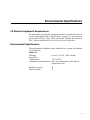
Environmental Specifications
CE Electrical Equipment Requirements
For information regarding the equipment needed to provide the electrical
service requirements listed in “Specifications” on page 3-10, please refer to
specification EN-309, “Plug, Outlet and Socket Couplers for Industrial
Uses,” listed in the official Journal of the European Communities.
Environmental Specifications
The environmental conditions under which the laser system will function
are listed below:
Indoor use
Vibration:
< 1.5 m/s2 (0.15 G), 15 Hz–200 Hz
Laser Head
Temperature:
10°C to 40°C
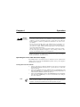
Maximum relative humidity: < 80% non-condensing over the allowed
temperature range
Insulation category:
Pollution degree:
II
2
v
Table of Contents
Preface . . . . . . . . . . . . . . . . . . . . . . . . . . . . . . . . . . . . . . . . . . . . . . . . . . . . . . . . . . . . . . iii
Environmental Specifications. . . . . . . . . . . . . . . . . . . . . . . . . . . . . . . . . . . . . . . . . . . . v
CE Electrical Equipment Requirements . . . . . . . . . . . . . . . . . . . . . . . . . . . . . . . . . . . . . . . . . . . . . . . . v
Environmental Specifications . . . . . . . . . . . . . . . . . . . . . . . . . . . . . . . . . . . . . . . . . . . . . . . . . . . . . . . . v
Warning Conventions . . . . . . . . . . . . . . . . . . . . . . . . . . . . . . . . . . . . . . . . . . . . . . . . . . xi
Standard Units . . . . . . . . . . . . . . . . . . . . . . . . . . . . . . . . . . . . . . . . . . . . . . . . . . . . . . . . xiii
Unpacking and Inspection . . . . . . . . . . . . . . . . . . . . . . . . . . . . . . . . . . . . . . . . . . . . . . xv
Unpacking Your Laser . . . . . . . . . . . . . . . . . . . . . . . . . . . . . . . . . . . . . . . . . . . . . . . . . . . . . . . . . . . . . xv
System Components . . . . . . . . . . . . . . . . . . . . . . . . . . . . . . . . . . . . . . . . . . . . . . . . . . . . . . . . . . . . . . xv
Accessories . . . . . . . . . . . . . . . . . . . . . . . . . . . . . . . . . . . . . . . . . . . . . . . . . . . . . . . . . . . . . . . . . . . . . xv
Chapter 1: Introduction . . . . . . . . . . . . . . . . . . . . . . . . . . . . . . . . . . . . . . . . . . . . . . . . . 1-1
General Information . . . . . . . . . . . . . . . . . . . . . . . . . . . . . . . . . . . . . . . . . . . . . . . . . . . . . . . . . . . . . . . 1-1
Patents . . . . . . . . . . . . . . . . . . . . . . . . . . . . . . . . . . . . . . . . . . . . . . . . . . . . . . . . . . . . . . . . . . . . . . . . . 1-3
Chapter 2: Laser Safety. . . . . . . . . . . . . . . . . . . . . . . . . . . . . . . . . . . . . . . . . . . . . . . . . 2-1
General Hazards . . . . . . . . . . . . . . . . . . . . . . . . . . . . . . . . . . . . . . . . . . . . . . . . . . . . . . . . . . . . . . . . . 2-1
Precautions for the Safe Operation of Class IIIb High Power Lasers . . . . . . . . . . . . . . . . . . . . . . . . . 2-2
Safety Devices . . . . . . . . . . . . . . . . . . . . . . . . . . . . . . . . . . . . . . . . . . . . . . . . . . . . . . . . . . . . . . . . . . . 2-3
On/Off AC Power Switch . . . . . . . . . . . . . . . . . . . . . . . . . . . . . . . . . . . . . . . . . . . . . . . . . . . . . . . . 2-4
AC Power Indicator . . . . . . . . . . . . . . . . . . . . . . . . . . . . . . . . . . . . . . . . . . . . . . . . . . . . . . . . . . . . 2-4
Enable Indicator . . . . . . . . . . . . . . . . . . . . . . . . . . . . . . . . . . . . . . . . . . . . . . . . . . . . . . . . . . . . . . . 2-5
Emission Keyswitch . . . . . . . . . . . . . . . . . . . . . . . . . . . . . . . . . . . . . . . . . . . . . . . . . . . . . . . . . . . . 2-5
Stable Indicator . . . . . . . . . . . . . . . . . . . . . . . . . . . . . . . . . . . . . . . . . . . . . . . . . . . . . . . . . . . . . . . 2-5
Emission Indicator . . . . . . . . . . . . . . . . . . . . . . . . . . . . . . . . . . . . . . . . . . . . . . . . . . . . . . . . . . . . . 2-5
Internal/External Emission Control Switch . . . . . . . . . . . . . . . . . . . . . . . . . . . . . . . . . . . . . . . . . . . 2-6
Internal/External Power Control Switch . . . . . . . . . . . . . . . . . . . . . . . . . . . . . . . . . . . . . . . . . . . . . 2-6
Safety Interlocks . . . . . . . . . . . . . . . . . . . . . . . . . . . . . . . . . . . . . . . . . . . . . . . . . . . . . . . . . . . . . . 2-6
Maximum Emission Levels . . . . . . . . . . . . . . . . . . . . . . . . . . . . . . . . . . . . . . . . . . . . . . . . . . . . . . . . . . 2-7
Requirements for Safely Operating the Excelsior Laser with a User-Provided Control Device . . . . . . 2-8
Schedule of Maintenance in Accordance with Center for Devices
and Radiological Health (CDRH) Regulations . . . . . . . . . . . . . . . . . . . . . . . . . . . . . . . . . . . . . . . . 2-8
Excelsior Radiation Safety Control Drawings . . . . . . . . . . . . . . . . . . . . . . . . . . . . . . . . . . . . . . . . . . . . 2-9
Excelsior Warning Labels . . . . . . . . . . . . . . . . . . . . . . . . . . . . . . . . . . . . . . . . . . . . . . . . . . . . . . . . . . . 2-10
Label Translations . . . . . . . . . . . . . . . . . . . . . . . . . . . . . . . . . . . . . . . . . . . . . . . . . . . . . . . . . . . . . 2-11
Waste Electrical and Electronic Equipment Recycling Label . . . . . . . . . . . . . . . . . . . . . . . . . . . . . . . . 2-11
Sources for Additional Information . . . . . . . . . . . . . . . . . . . . . . . . . . . . . . . . . . . . . . . . . . . . . . . . . . . . 2-12
Laser Safety Standards . . . . . . . . . . . . . . . . . . . . . . . . . . . . . . . . . . . . . . . . . . . . . . . . . . . . . . . . . 2-12
Equipment and Training . . . . . . . . . . . . . . . . . . . . . . . . . . . . . . . . . . . . . . . . . . . . . . . . . . . . . . . . 2-13
vii
Excelsior Diode-Pumped CW Lasers
Chapter 3: System Description . . . . . . . . . . . . . . . . . . . . . . . . . . . . . . . . . . . . . . . . . . 3-1
A Brief Review of Laser Theory . . . . . . . . . . . . . . . . . . . . . . . . . . . . . . . . . . . . . . . . . . . . . . . . . . . . . .3-1
Emission and Absorption of Light . . . . . . . . . . . . . . . . . . . . . . . . . . . . . . . . . . . . . . . . . . . . . . . . . .3-1
Population Inversion . . . . . . . . . . . . . . . . . . . . . . . . . . . . . . . . . . . . . . . . . . . . . . . . . . . . . . . . . . . .3-2
Resonant Optical Cavity and Cavity Modes . . . . . . . . . . . . . . . . . . . . . . . . . . . . . . . . . . . . . . . . . .3-3
Single Longitudinal Mode Operation . . . . . . . . . . . . . . . . . . . . . . . . . . . . . . . . . . . . . . . . . . . . . . .3-4
Nd3+ as a Laser Medium . . . . . . . . . . . . . . . . . . . . . . . . . . . . . . . . . . . . . . . . . . . . . . . . . . . . . . . .3-4
Diode-Pumped Laser Design . . . . . . . . . . . . . . . . . . . . . . . . . . . . . . . . . . . . . . . . . . . . . . . . . . . . .3-5
Frequency Doubling . . . . . . . . . . . . . . . . . . . . . . . . . . . . . . . . . . . . . . . . . . . . . . . . . . . . . . . . . . . .3-7
The Excelsior Lasers . . . . . . . . . . . . . . . . . . . . . . . . . . . . . . . . . . . . . . . . . . . . . . . . . . . . . . . . . . . . . .3-8
The Excelsior Laser Head . . . . . . . . . . . . . . . . . . . . . . . . . . . . . . . . . . . . . . . . . . . . . . . . . . . . . . .3-8
The Excelsior Power Supply/Controller . . . . . . . . . . . . . . . . . . . . . . . . . . . . . . . . . . . . . . . . . . . . .3-9
Specifications . . . . . . . . . . . . . . . . . . . . . . . . . . . . . . . . . . . . . . . . . . . . . . . . . . . . . . . . . . . . . . . . . . . .3-10
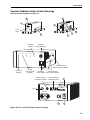
Outline Drawings . . . . . . . . . . . . . . . . . . . . . . . . . . . . . . . . . . . . . . . . . . . . . . . . . . . . . . . . . . . . . . . . .3-12
Chapter 4: Controls, Indicators and Connections . . . . . . . . . . . . . . . . . . . . . . . . . . . 4-1
The Excelsior Laser Head . . . . . . . . . . . . . . . . . . . . . . . . . . . . . . . . . . . . . . . . . . . . . . . . . . . . . . . . . .4-1
Controls . . . . . . . . . . . . . . . . . . . . . . . . . . . . . . . . . . . . . . . . . . . . . . . . . . . . . . . . . . . . . . . . . . . . .4-1
Connections . . . . . . . . . . . . . . . . . . . . . . . . . . . . . . . . . . . . . . . . . . . . . . . . . . . . . . . . . . . . . . . . . .4-2
Excelsior Power Supply/Controller . . . . . . . . . . . . . . . . . . . . . . . . . . . . . . . . . . . . . . . . . . . . . . . . . . . .4-2
Front Panel . . . . . . . . . . . . . . . . . . . . . . . . . . . . . . . . . . . . . . . . . . . . . . . . . . . . . . . . . . . . . . . . . . .4-2
Back Panel . . . . . . . . . . . . . . . . . . . . . . . . . . . . . . . . . . . . . . . . . . . . . . . . . . . . . . . . . . . . . . . . . . .4-4
Controls on the Power Supply Side Panel . . . . . . . . . . . . . . . . . . . . . . . . . . . . . . . . . . . . . . . . . . .4-6
Chapter 5: Installation. . . . . . . . . . . . . . . . . . . . . . . . . . . . . . . . . . . . . . . . . . . . . . . . . . 5-1
Power . . . . . . . . . . . . . . . . . . . . . . . . . . . . . . . . . . . . . . . . . . . . . . . . . . . . . . . . . . . . . . . . . . . . . . . . . .5-1
Thermal Management . . . . . . . . . . . . . . . . . . . . . . . . . . . . . . . . . . . . . . . . . . . . . . . . . . . . . . . . . . . . .5-1
Installing the Hardware . . . . . . . . . . . . . . . . . . . . . . . . . . . . . . . . . . . . . . . . . . . . . . . . . . . . . . . . . . . . .5-3
Mounting the Laser Head . . . . . . . . . . . . . . . . . . . . . . . . . . . . . . . . . . . . . . . . . . . . . . . . . . . . . . . .5-3
Mounting the Power Supply . . . . . . . . . . . . . . . . . . . . . . . . . . . . . . . . . . . . . . . . . . . . . . . . . . . . . .5-3
Connecting the Cables . . . . . . . . . . . . . . . . . . . . . . . . . . . . . . . . . . . . . . . . . . . . . . . . . . . . . . . . . .5-3
External Control Connector . . . . . . . . . . . . . . . . . . . . . . . . . . . . . . . . . . . . . . . . . . . . . . . . . . . . . .5-4
Chapter 6: Operation. . . . . . . . . . . . . . . . . . . . . . . . . . . . . . . . . . . . . . . . . . . . . . . . . . . 6-1
Operating the Laser from the Power Supply . . . . . . . . . . . . . . . . . . . . . . . . . . . . . . . . . . . . . . . . . . . .6-1
Turning the Laser On and Off . . . . . . . . . . . . . . . . . . . . . . . . . . . . . . . . . . . . . . . . . . . . . . . . . . . .6-1
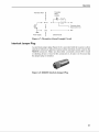
Operating the Laser Using the External Control Interface . . . . . . . . . . . . . . . . . . . . . . . . . . . . . . . . . .6-2
Turning the Laser On and Off (Pin 2) . . . . . . . . . . . . . . . . . . . . . . . . . . . . . . . . . . . . . . . . . . . . . . .6-2
Using the External Enable Signal (Pin 3) . . . . . . . . . . . . . . . . . . . . . . . . . . . . . . . . . . . . . . . . . . . .6-3
Using the External Stable Signal (Pin 1) . . . . . . . . . . . . . . . . . . . . . . . . . . . . . . . . . . . . . . . . . . . .6-3
Using the Service Alarm Signal (Pin 10) . . . . . . . . . . . . . . . . . . . . . . . . . . . . . . . . . . . . . . . . . . . .6-4
Changing Laser Output Power (Pin 8) . . . . . . . . . . . . . . . . . . . . . . . . . . . . . . . . . . . . . . . . . . . . . .6-4
Monitoring Laser Output Power (Pin 5) . . . . . . . . . . . . . . . . . . . . . . . . . . . . . . . . . . . . . . . . . . . . .6-6
Using the 12 Vdc Output (Pin 9) . . . . . . . . . . . . . . . . . . . . . . . . . . . . . . . . . . . . . . . . . . . . . . . . . .6-6
Using the Thermistor Alarm (Pin 13) . . . . . . . . . . . . . . . . . . . . . . . . . . . . . . . . . . . . . . . . . . . . . . .6-6
Interlock Jumper Plug . . . . . . . . . . . . . . . . . . . . . . . . . . . . . . . . . . . . . . . . . . . . . . . . . . . . . . . . . . . . . .6-7
Chapter 7: Troubleshooting and Service . . . . . . . . . . . . . . . . . . . . . . . . . . . . . . . . . . 7-1
Maintenance . . . . . . . . . . . . . . . . . . . . . . . . . . . . . . . . . . . . . . . . . . . . . . . . . . . . . . . . . . . . . . . . . . . . .7-1
Service Training Programs . . . . . . . . . . . . . . . . . . . . . . . . . . . . . . . . . . . . . . . . . . . . . . . . . . . . . . . . . .7-2
Troubleshooting . . . . . . . . . . . . . . . . . . . . . . . . . . . . . . . . . . . . . . . . . . . . . . . . . . . . . . . . . . . . . . . . . .7-2
Replacement Parts . . . . . . . . . . . . . . . . . . . . . . . . . . . . . . . . . . . . . . . . . . . . . . . . . . . . . . . . . . . . . . . .7-5
viii
Table of Contents
Customer Service . . . . . . . . . . . . . . . . . . . . . . . . . . . . . . . . . . . . . . . . . . . . . . . . . . . . . . . . . . . . . . . . . 7-6
Warranty . . . . . . . . . . . . . . . . . . . . . . . . . . . . . . . . . . . . . . . . . . . . . . . . . . . . . . . . . . . . . . . . . . . . 7-6
Returning the Instrument for Repair . . . . . . . . . . . . . . . . . . . . . . . . . . . . . . . . . . . . . . . . . . . . . . . 7-6
Service Centers . . . . . . . . . . . . . . . . . . . . . . . . . . . . . . . . . . . . . . . . . . . . . . . . . . . . . . . . . . . . . . . . . . 7-7
Notes
Report Form for Problems and Solutions
List of Figures
Figure 1-1: The Standard DPSS Excelsior Laser Head . . . . . . . . . . . . . . . . . . . . . . . . . . . . . . . . . . . . 1-1
Figure 2-1: These standard safety warning labels are appropriate for use as entry warning signs (EN 608251: 2007, ANSI Z136.1, Section 4.7). . . . . . . . . . . . . . . . . . . . . . . . . . . . . . . . . . . . . . . . . . . . . . . . 2-2
Figure 2-2: Folded Metal Beam Target . . . . . . . . . . . . . . . . . . . . . . . . . . . . . . . . . . . . . . . . . . . . . . . . 2-2
Figure 2-3: Laser Head Manual Shutter . . . . . . . . . . . . . . . . . . . . . . . . . . . . . . . . . . . . . . . . . . . . . . . . 2-3
Figure 2-4: Excelsior Power Supply Safety Devices . . . . . . . . . . . . . . . . . . . . . . . . . . . . . . . . . . . . . . 2-4
Figure 2-5: Remote Interlock Jumper Plug . . . . . . . . . . . . . . . . . . . . . . . . . . . . . . . . . . . . . . . . . . . . . 2-6
Figure 2-6: Excelsior Radiation Control Drawings . . . . . . . . . . . . . . . . . . . . . . . . . . . . . . . . . . . . . . . . 2-9
Figure 2-7: Excelsior Warning Labels . . . . . . . . . . . . . . . . . . . . . . . . . . . . . . . . . . . . . . . . . . . . . . . . . 2-10
Figure 3-1: A Typical Four-level Transition Scheme . . . . . . . . . . . . . . . . . . . . . . . . . . . . . . . . . . . . . . 3-2
Figure 3-2: Frequency Distribution of Longitudinal Modes . . . . . . . . . . . . . . . . . . . . . . . . . . . . . . . . . . 3-3
Figure 3-3: Energy Level Scheme for the Nd Ion in YAG . . . . . . . . . . . . . . . . . . . . . . . . . . . . . . . . . . 3-4
Figure 3-4: Nd3+ absorption spectra compared to emission spectra of a Black Body Source (a) and a Diode
Laser (b). . . . . . . . . . . . . . . . . . . . . . . . . . . . . . . . . . . . . . . . . . . . . . . . . . . . . . . . . . . . . . . . . . . . . 3-6
Figure 3-5: Mode Matching . . . . . . . . . . . . . . . . . . . . . . . . . . . . . . . . . . . . . . . . . . . . . . . . . . . . . . . . . 3-6
Figure 3-6: Remote Interlock Jumper Plug . . . . . . . . . . . . . . . . . . . . . . . . . . . . . . . . . . . . . . . . . . . . . 3-9
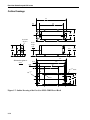
Figure 3-7: Outline Drawing of the Excelsior DPSS-CDRH Laser Head . . . . . . . . . . . . . . . . . . . . . . . 3-12
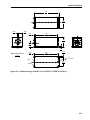
Figure 3-8: Outline Drawing of the Excelsior DPSS-XC-CDRH Laser Head . . . . . . . . . . . . . . . . . . . . 3-13
Figure 3-9: Outline Drawing of Excelsior Power Supply/Controller . . . . . . . . . . . . . . . . . . . . . . . . . . . 3-14
Figure 4-1: The Standard Excelsior Laser Head . . . . . . . . . . . . . . . . . . . . . . . . . . . . . . . . . . . . . . . . . 4-1
Figure 4-2: Shutter “Open/Close” Designations . . . . . . . . . . . . . . . . . . . . . . . . . . . . . . . . . . . . . . . . . . 4-1
Figure 4-3: The Power Supply/Controller Front Panel . . . . . . . . . . . . . . . . . . . . . . . . . . . . . . . . . . . . . 4-2
Figure 4-4: The Power Supply/Controller Back Panel . . . . . . . . . . . . . . . . . . . . . . . . . . . . . . . . . . . . . 4-4
Figure 4-5: Remote Interlock Jumper Plug . . . . . . . . . . . . . . . . . . . . . . . . . . . . . . . . . . . . . . . . . . . . . 4-4
Figure 4-6: External Control Connector Pin Numbering . . . . . . . . . . . . . . . . . . . . . . . . . . . . . . . . . . . . 4-5
Figure 4-7: The Power Supply Side Panel . . . . . . . . . . . . . . . . . . . . . . . . . . . . . . . . . . . . . . . . . . . . . . 4-6
Figure 5-1: Heat Dissipation of the Laser Head . . . . . . . . . . . . . . . . . . . . . . . . . . . . . . . . . . . . . . . . . . 5-2
Figure 5-2: Maximum Permissible Heatsink Thermal Impedance . . . . . . . . . . . . . . . . . . . . . . . . . . . . 5-2
Figure 5-3: Remote Connector Jumper Plug . . . . . . . . . . . . . . . . . . . . . . . . . . . . . . . . . . . . . . . . . . . . 5-3
Figure 5-4: External CONTrol Interface Connector Pin Numbering . . . . . . . . . . . . . . . . . . . . . . . . . . . 5-4
Figure 6-1: Example of a typical laser On/Off control circuit. . . . . . . . . . . . . . . . . . . . . . . . . . . . . . . . . 6-2
Figure 6-2: Example Circuit for a Remote Enable Signal/Indicator . . . . . . . . . . . . . . . . . . . . . . . . . . . 6-3
Figure 6-3: Example Circuit for a Remote Stable/Emission Signal/Indicator . . . . . . . . . . . . . . . . . . . . 6-3
Figure 6-4: Example or a Service Alarm Circuit . . . . . . . . . . . . . . . . . . . . . . . . . . . . . . . . . . . . . . . . . . 6-4
Figure 6-5: Example Circuits for Varying Laser Output Power . . . . . . . . . . . . . . . . . . . . . . . . . . . . . . 6-5
Figure 6-6: The 12 Vdc Supply Circuit . . . . . . . . . . . . . . . . . . . . . . . . . . . . . . . . . . . . . . . . . . . . . . . . . 6-6
Figure 6-7: Thermistor Alarm Example Circuit . . . . . . . . . . . . . . . . . . . . . . . . . . . . . . . . . . . . . . . . . . . 6-7
Figure 6-8: Remote Interlock Jumper Plug . . . . . . . . . . . . . . . . . . . . . . . . . . . . . . . . . . . . . . . . . . . . . 6-7
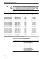
List of Tables
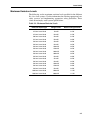
Table 1-1: Excelsior Lasers. . . . . . . . . . . . . . . . . . . . . . . . . . . . . . . . . . . . . . . . . . . . . . . . . . . . . . . . . . 1-2
Table 1-2: Excelsior Power Supply/Controllers . . . . . . . . . . . . . . . . . . . . . . . . . . . . . . . . . . . . . . . . . . 1-2
Table 2-1: Maximum Emission Levels . . . . . . . . . . . . . . . . . . . . . . . . . . . . . . . . . . . . . . . . . . . . . . . . . 2-7
ix
Excelsior Diode-Pumped CW Lasers
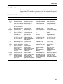
Table 2-2: Label Translations . . . . . . . . . . . . . . . . . . . . . . . . . . . . . . . . . . . . . . . . . . . . . . . . . . . . . . . .2-11
Table 4-1: External Control (CONT) Connector Pin Functions . . . . . . . . . . . . . . . . . . . . . . . . . . . . . . .4-5
Table 5-1: Heat Dissipation, Laser Head. . . . . . . . . . . . . . . . . . . . . . . . . . . . . . . . . . . . . . . . . . . . . . . .5-2
Table 5-2: Lasers capable of variable output power . . . . . . . . . . . . . . . . . . . . . . . . . . . . . . . . . . . . . . .5-4
Table 5-3: External Control (CONT) Connector Pin Functions . . . . . . . . . . . . . . . . . . . . . . . . . . . . . . .5-5
Table 6-1: Lasers capable of variable output power . . . . . . . . . . . . . . . . . . . . . . . . . . . . . . . . . . . . . . .6-4
Table 6-2: Recommended Parameters for R1 and VR1 in Figure 6-5 . . . . . . . . . . . . . . . . . . . . . . . . . .6-5
Table 7-1: Replacement Parts. . . . . . . . . . . . . . . . . . . . . . . . . . . . . . . . . . . . . . . . . . . . . . . . . . . . . . . .7-5
x
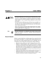
Warning Conventions
The following warnings are used throughout this manual to draw your
attention to situations or procedures that require extra attention. They warn
of hazards to your health, damage to equipment, sensitive procedures, and
exceptional circumstances. All messages are set apart by a thin line above
and below the text as shown here.
Danger!
Laser radiation is present.
Laser Radiation
Danger!
Condition or action may present a hazard to personal safety.
Danger!
Condition or action may present an electrical hazard to personal
safety.
Warning!
Condition or action may cause damage to equipment.
Warning!
ESD
Action may cause electrostatic discharge and cause damage to equipment.
Caution!
Condition or action may cause poor performance or error.
Note
Don't
Touch!
Eyewear
Required
Text describes exceptional circumstances or makes a special reference.
Do not touch.
Appropriate laser safety eyewear should be worn during this operation.
Refer to the manual before operating or using this device.
xi
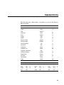
Standard Units
The following units, abbreviations, and prefixes are used in this SpectraPhysics manual:
Quantity
Unit
Abbreviation
mass
kilogram
kg
length
meter
m
second
s
hertz
Hz
newton
N
energy
joule
J
power
watt
W
electric current
ampere
A
electric charge
coulomb
C
electric potential
volt
V
resistance
ohm
Ω
inductance
henry
H
magnetic flux
weber
Wb
tesla
T
luminous intensity
candela
cd
temperature
Celsius
C
pressure
pascal
Pa
capacitance
farad
F
angle
radian
rad
time
frequency
force
magnetic flux density
Prefixes
tera
giga
mega
kilo
12
T
deci
9
G
centi
6
M
milli
3
k
micro
(10 )
(10 )
(10 )
(10 )
d
nano
-2
c
pico
-3
m
femto
-6
μ
atto
(10-1)
(10 )
(10 )
(10 )
(10-9)
n
-12
p
-15
f
-18
a
(10 )
(10 )
(10 )
xiii
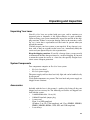
Unpacking and Inspection
Unpacking Your Laser
Your Excelsior laser was packed with great care, and its container was
inspected prior to shipment—it left Spectra-Physics in good condition.
Upon receiving your system, immediately inspect the outside of the shipping container. If there is any major damage (holes in the container, crushing, etc.), insist that a representative of the carrier be present when you
unpack the contents.
Carefully inspect your laser system as you unpack it. If any damage is evident, such as dents or scratches on the covers, etc., immediately notify the
carrier and your Spectra-Physics sales representative.
Keep the shipping container. If you file a damage claim, you may need it
to demonstrate that the damage occurred as a result of shipping. If you need
to return the system for service at a later date, the specially designed container assures adequate protection.
System Components
Two components comprise an Excelsior laser system:
• Excelsior laser head
• Excelsior power supply
The power supply and laser head are fairly light and can be handled easily
by one person.
Verify both components are present. The laser head and power supply are
shipped in one container.
Accessories
Included with the laser is this manual, a packing slip listing all the parts
shipped and an accessory kit. The following accessories are shipped standard with the system:
• 1 LASER HEAD cable, 1.8 m (6 ft)
• 1 REMOTE interlock jumper plug
• 1 power cord
Japan: 2 m (PSE compliant)
All others: 2 m (UL, CSA compliant) and 2.5 m (SEMKO, NEMKO,
FIMKO, DEMKO, KEMA, VDE, SEV and ÖVE compliant)
• 2 sets of keys
xv
Chapter 1
Introduction
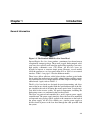
General Information
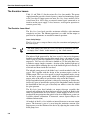
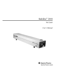
Figure 1-1: The Standard DPSS Excelsior Laser Head
Spectra-Physics Excelsior lasers produce a continuous laser beam from an
exceptionally compact package. These small, rugged, diode-pumped, solidstate lasers are especially well suited for applications requiring a low-noise,
high quality, continuous wave (CW) beam. All Excelsior lasers are
designed to operate at constant output power. However, several models
allow the operator to vary laser power from 50% to 100% via an external
interface. Table 1-1 on page 1-2 lists the different models.
These lasers deliver efficient, stable light with the excellent spatial mode
that is critical for applications in graphics, photo finishing and flow cytometry. Individual Excelsior models operate in either single or multiple longitudinal mode. Again, refer to Table 1-1.
The Excelsior laser heads are designed for precision mounting and alignment of the beam, which, together with the specified boresight of the output, simplifies the task of designing the master optical train, or replacing a
laser head in the master system. All optical components, including the
diode pump source, are contained in the laser head itself.
The lasers are powered and controlled by a small, separate power supply/
controller unit. The power supply interface allows the laser to be monitored
and operated using analog signals applied to the connector on the back of
the power supply. All Excelsior models use a similar power supply to
deliver electrical power to the laser head through the cable provided with
the system.
1-1
Excelsior Diode-Pumped CW Lasers
Note
Excelsior laser heads are completely interchangeable with same models,
as are the power supplies. In case the laser head or power supply needs
to be exchanged, the new unit is simply fastened in place and the
cabling connected. No adjustment or calibration is needed.
Table 1-1: Excelsior Lasers1
Excelsior Model
Power
Longitudinal Mode
Adjustable?
Excelsior-473-10-CDRH
10 mW@ 473 nm
single
50 to 100%
Excelsior-473-50-CDRH
50 mW@ 473 nm
single
50 to 100%
Excelsior-505-20-CDRH
20 mW@ 505 nm
multi
50 to 100%
Excelsior-515-50-CDRH
50 mW@ 515 nm
single
50 to 100%
Excelsior-532-20M-CDRH
20 mW @532 nm
multi
no
Excelsior-532-50-CDRH
50 mW @532 nm
single
50 to 100%
Excelsior-532-100-CDRH
100 mW @532 nm
single
50 to 100%
Excelsior-532-150-CDRH
150 mW @532 nm
single
50 to 100%
Excelsior-532-200-CDRH
200 mW @532 nm
single
50 to 100%
Excelsior-532-300-CDRH
300 mW @532 nm
single
no
Excelsior-542-50-CDRH
50 mW @542 nm
single
50 to 100%
Excelsior-561-20-CDRH
20 mW @561 nm
single
50 to 100%
Excelsior-561-50-CDRH
50 mW @561 nm
single
50 to 100%
Excelsior-561-100-CDRH
100 mW @561 nm
single
50 to 100%
Excelsior-561-150-CDRH
150 mW @561 nm
single
50 to 100%
Excelsior-594-50-CDRH
50 mW @594 nm
multi
50 to 100%
Excelsior-1064-500-CDRH
500 mW @1064 nm
single
50 to 100%
Excelsior-1064-800-CDRH
800 mW @1064 nm
single
50 to 100%
1
Values are for illustration only; refer to Chapter 3 for specified values.
Table 1-2: Excelsior Power Supply/Controllers
Power Supply Models
1-2
Used With These Lasers
Excelsior-PS-CDRH
Excelsior-473-10/50-CDRH
Excelsior-532- 20M-CDRH
Excelsior-532-50/100/150/200-CDRH
Excelsior-542-50-CDRH
Excelsior-561-25/50-CDRH
Excelsior-1064-500/800-CDRH
Excelsior-PS-XC-CDRH
Excelsior-505-20-CDRH
Excelsior-515-50-CDRH
Excelsior-532-300-CDRH
Excelsior-561-100/150-CDRH
Excelsior-594-50-CDRH
Introduction
Patents
The Excelsior lasers are manufactured under one or more of the following
US patents:
4,756,003
4,872,177
5,870,415
7,189,703
3,046,562
(Japanese patent)
1-3
Excelsior Diode-Pumped CW Lasers
1-4
Chapter 2
Danger!
Laser Radiation
Note
Laser Safety
The Spectra-Physics Excelsior lasers are Class IIIb and Class 4—High
Power Lasers whose beams are, by definition, safety hazards. Take precautions to prevent accidental exposure to both direct and reflected
beams. Diffuse as well as specular beam reflections can cause severe
eye damage.
Because the infrared (IR) beam of the 1064 nm lasers is invisible, it is
especially dangerous. Infrared radiation passes easily through the cornea of the eye, which, when focussed on the retina, can cause instantaneous and permanent damage!
Always wear proper eye protection when working on the laser and follow the safety precautions given in this chapter. Refer to the product
model number label for wavelength (nm).
This user information is in compliance with section 1040.10 of the
CDRH Laser Products Performance Standards from the Health and
Safety Act of 1968.
General Hazards
Hazards associated with the use of diode-pumped lasers generally fall into
the categories listed below. At all times while working with these lasers,
please be aware of these potential hazards and act accordingly. You are
responsible for your health and the health of those working around you.
• Exposure to laser radiation can result in damage to the eyes or skin.
• Exposure to chemical hazards, such as particulate matter or gaseous
substances, can be health hazards when they are released as a result of
laser material processing or as by-products of the lasing process itself.
When these lasers are used to pump dye laser systems, be aware that
the dyes used can be extremely hazardous to your health if inhaled or,
in some cases, even touched.
• Exposure to high-voltage electrical circuits present in the laser power
supply and associated circuits can result in shock or even death.
• Possible health risks are present if pressurized hoses, cylinders, liquids
and gasses used in laser systems are damaged or misused.
2-1
Excelsior Diode-Pumped CW Lasers
Precautions for the Safe Operation of
Class IIIb High Power Lasers
•
•
•
•
•
•
•
•
•
•
Wear protective eyewear at all times; selection depends on the wavelength and intensity of the radiation, the conditions of use, and the
visual function required. Protective eyewear is available from suppliers listed in the Laser Focus World, Lasers and Optronics, and Photonics Spectra buyer’s guides. Consult the ANSI and ACGIH standards
listed at the end of this section for guidance.
Maintain a high ambient light level in the laser operation area so the
eye’s pupil remains constricted, reducing the possibility of damage.
To avoid unnecessary radiation exposure, keep the protective cover on
the laser head at all times.
Avoid looking at the output beam; diffuse reflections are hazardous.
Establish a controlled access area for laser operation. Limit access to
those trained in the principles of laser safety.
Enclose beam paths wherever possible.
Post prominent warning signs near the laser operating area (Figure 2-1).
Install the laser so that the beam is either above or below eye level.
Set up shields to prevent any unnecessary specular reflections or
beams from escaping the laser operation area.
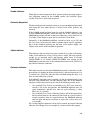
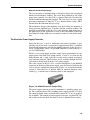
Set up a beam dump to capture the laser beam and prevent accidental
exposure (Figure 2-2).
DANGER
DANGER
VISIBLE AND/OR INVISIBLE
LASER RADIATION
VISIBLE AND/OR INVISIBLE
LASER RADIATION
AVOID EYE OR SKIN EXPOSURE TO
AVOID EYE OR SKIN EXPOSURE TO
DIRECT OR SCATTERED RADIATION
DIRECT OR SCATTERED RADIATION
473, 505, 515, 532, 542, 561, 584 NM
1064 NM WAVELENGTH
WAVELENGTH
MAXIMUM OUTPUT POWER 1.5 W
MAXIMUM OUTPUT POWER 500 mW
CLASS IIIb LASER PRODUCT
CLASS 4 LASER PRODUCT
VISIBLE AND/OR INVISIBLE
LASER RADIATION
VISIBLE AND/OR INVISIBLE
LASER RADIATION
AVOID EYE OR SKIN EXPOSURE TO
DIRECT OR SCATTERED RADIATION
AVOID EYE OR SKIN EXPOSURE TO
DIRECT OR SCATTERED RADIATION
CLASS 3B LASER PRODUCT
CLASS 4 LASER PRODUCT
473, 505, 515, 532, 542, 561, 594 NM WAVELENGTH
MAXIMUM OUTPUT POWER 500 mW
1064 NM WAVELENGTH
MAXIMUM OUTPUT POWER 1.5 W
Figure 2-1: These standard safety warning labels are appropriate for
use as entry warning signs (EN 60825-1: 2007, ANSI Z136.1, Section 4.7).
Figure 2-2: Folded Metal Beam Target
2-2
Laser Safety
Danger!
Laser Radiation
Danger!
Use of controls or adjustments, or performing the procedures described
in this manual in a manner other than specified may result in hazardous
radiation exposure.
Operating this laser without due regard for these precautions or in a
manner that does not comply with recommended procedures may be
dangerous. At all times during installation, maintenance or service of
your laser, avoid unnecessary exposure to laser or collateral radiation*
that exceeds the accessible emission limits listed in “Performance Standards for Laser Products,” United States Code of Federal Regulations,
21CFR1040.10(d).
* Any electronic product radiation, except laser radiation, emitted by a laser product as a
result of or necessary for the operation of a laser incorporated into that product.
Follow the instructions contained in this manual to ensure proper installation and safe operation of your laser.
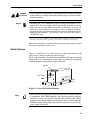
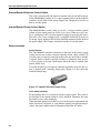
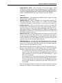
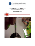
Safety Devices
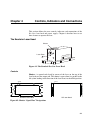
Figure 2-3 and Figure 2-4 (on the next page) show the locations of the
safety devices on the laser head and power supply.
The laser head includes a manually operated shutter. All control and monitoring of the laser is through the power supply or, optionally, through the
CONTrol connector on the power supply back panel.
Shutter
AVOID EXPOSU
RE
VISIB
INVISI
IS EMITT
LE AND
LASER
EDBLE
FROM
/OR
THISRADIA
TION
APER
TURE
0420-790
0
Laser Beam
LASER
RADIA
TION
DUCT
ER PRO
3B LAS
CLASS
W,
BEAM ,
< 500m
RE TO
POWER
EXPOSU
946 nm
AVOID
OUTPUT
473 nm,
M CW
MAXIMU
1064 nm;
nm,
532
NGTH
WAVELE
Figure 2-3: Laser Head Manual Shutter
Note
There is no emission indicator on the laser head itself. In order to remain
in compliance with CDRH Standards, the laser head must be operated
using the 1.8 meter laser control cable provided with the system. When
connected to the power supply, this cable keeps the laser head within the
CDRH-specified distance from the emission indicator located on the
power supply front panel.
2-3
Excelsior Diode-Pumped CW Lasers
Enable
("Laser Ready")
Indicator
Internal/External
Emission Control Switch
Emission
Indicator
Internal/External
Power Control Switch
EMISSION
POWER
ENABLE
STABLE
STBY
SERVICE
ON
EMISSION
PWR CONT
EXT
INT
CONT
EMISSION
EXT
INT
POWER
ON
OFF
AC Power
Indicator
Remote Safety
Interlock Connector
Fuse
FUSE
1A
AC Power
On/Off Switch
Laser Power
Stable Indicator
Emission
On/Off Keyswitch
External Control
Cable Connector
Spectra-Physics
REMOTE
1335 Terra Bella Avenue, Mountain View, CA.
CONT
94043
MANUFACTURED IN JAPAN
MFG P/N
MONTH/YEAR
S/N
A150-0110
LASER
AC POWER
100-240V, 50/60Hz
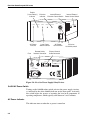
Figure 2-4: Excelsior Power Supply Safety Devices
On/Off AC Power Switch
Turning on the POWER rocker switch activates the power supply circuitry,
as indicated by the white POWER indicator on the front panel. Activating
this switch begins the process of warming the laser head components to
operating temperature, which typically takes between 2 and 5 minutes.
AC Power Indicator
This indicator turns on when the ac power is turned on.
2-4
Laser Safety
Enable Indicator
When the laser head components have warmed to their operating temperature (following turning on the POWER switch), this indicator glows
steadily. The laser is now ready to operate.
Emission Keyswitch
The keyswitch provides interlock safety to prevent unauthorized personnel
from using the laser when the key is turned to the STBY position and
removed.
If the POWER switch has been turned on and the ENABLE indicator is on
and the EMISSION CONTROL switch has been set to INT, turning on the
EMISSION keyswitch will turn on the laser (following a safety delay of 3 to
5 seconds). If the shutter is open, the laser will emit a laser beam.
Optionally, if the EMISSION CONTROL switch has been set to EXT, the
Excelsior laser can be turned on when a suitable control signal is applied to
Pin 2 of the CONTrol connector on the back of the power supply. See
Chapter 6 for details of this method of operation.
Stable Indicator
This indicator turns on when laser power reaches its set value and becomes
stable, and it remains on as long as laser power is stable. The laser typically
reaches its set operating power and becomes stable about 10 seconds
(DPSS-CDRH) or 30 seconds (DPSS-XC-CDRH) after turning on the
EMISSION keyswitch or after an On command has been received at Pin 2 of
the CONTrol interface connector.
Emission Indicator
This indicator turns on when the EMISSION keyswitch is turned on (see the
prerequisites for turning on the keyswitch above), and emission occurs 3 to
5 seconds later. (Note: this indicator does not blink during the delay as it
does on some other laser systems).
If the REMOTE interlock circuit is opened (see the description below), laser
emission stops immediately and this indicator turns off. If the REMOTE
interlock switch is then closed again, one of the following actions occur:
• On a standard Class 3b laser or extended cavity (XC) laser, if the keyswitch is still in the ON position, the EMISSION indicator turns on
again immediately and the laser turns on again following a safety
delay of 3 to 5 seconds.
• On a standard Class 4 laser, if the keyswitch is still in the ON position,
the keyswitch must first be turned off, then back on again in order to
resume operation. After it is turned back on, the EMISSION indicator
turns on again and the laser will turn on again after a safety delay of 3
to 5 seconds.
Pin 1 of the CONTrol connector can be used to control an external emission
indicator. See Chapter 6 for an example of a circuit used for this purpose.
2-5
Excelsior Diode-Pumped CW Lasers
Internal/External Emission Control Switch
This slide switch provides the option to turn the laser on and off by means
of the EMISSION keyswitch, or via a signal applied to Pin 2 on the CONTrol
connector on the back of the power supply. See Chapter 6 for details on
how to use this option.
Internal/External Power Control Switch
The PWR CONTROL switch, when set to EXT, is used to enable external
control of laser output power for all Excelsior lasers. When set to INT, output is at full power. INT is also the required setting for operating the lowerpower Excelsior lasers. Output power is controlled externally by means of
an analog signal applied to Pin 8 of the CONTrol connector on the back of
the power supply. See Chapter 6 for details on how to use this option.
Safety Interlocks
Safety Interlock
The 2-pin REMOTE interlock connector on the back of the power supply
can be wired to one or more external, normally-closed safety switches, all
wired in series, to stop laser emission in the event any one of these switches
is opened. Such a switch is typically attached to a laboratory door or critical access point so that the switch opens when the door is opened, thus
turning off the laser.
To ensure that the laser can operate when this interlock is not used, the system is shipped with a shorting jumper plug (Figure 2-5) that closes the
interlock control loop.
Figure 2-5: REMOTE Interlock Jumper Plug
Cover Safety Interlocks
Do not open the Excelsior laser head or power supply covers. The system is
not designed to be operated with its covers removed. Therefore, the units
do not have cover safety interlocks.
When the diode pump laser in the Excelsior head requires replacement, the
entire laser head is replaced as a unit. Before starting any replacement procedure, the power supply must be disconnected from the AC outlet.
2-6
Laser Safety
Maximum Emission Levels
The following are the maximum emission levels possible for the different
Excelsior laser systems. Use this information for selecting appropriate laser
safety eyewear and implementing appropriate safety procedures. These
values do not imply actual system specifications.
Table 2-1: Maximum Emission Levels
Emission Wavelength
Design Power
808 nm Diode
Maximum Output Power
0.1 W
473 nm Laser Head
10 mW
0.1 W
473 nm Laser Head
50 mW
0.1 W
505 nm Laser Head
20 mW
0.1 W
515 nm Laser Head
50 mW
0.3 W
532 nm Laser Head
20 mW
0.5 W
532 nm Laser Head
50 mW
0.5 W
532 nm Laser Head
100 mW
0.5 W
532 nm Laser Head
150 mW
0.5 W
532 nm Laser Head
200 mW
0.5 W
532 nm Laser Head
300 mW
0.5 W
542 nm Laser Head
50 mW
0.3 W
561 nm Laser Head
25 mW
0.2 W
561 nm Laser Head
50 mW
0.2 W
561 nm Laser Head
100 mW
0.3 W
561 nm Laser Head
150 mW
0.3 W
594 nm Laser Head
50 mW
0.3 W
1064 nm Laser Head
500 mW
1.5 W
1064 nm Laser Head
800 mW
1.5 W
2-7
Excelsior Diode-Pumped CW Lasers
Requirements for Safely Operating the Excelsior Laser
with a User-Provided Control Device
When the Excelsior laser system is controlled by a device provided by the
user or by software written by the user, the following must be provided:
• A keyswitch —that limits access to the laser and prevents it from being
turned on. It can be a real key lock, a removable computer disk, a password that limits access to computer control software, or a similar
“key” implementation. The laser must only operate when the “key” is
present and in the “on” position.
• An emission indicator —that indicates laser energy is present or can be
accessed. It can be a “power-on” lamp, a computer display that flashes
a statement to this effect, or an indicator on the control equipment for
this purpose. It need not be marked as an emission indicator so long as
its function is obvious. Its presence is required on any control panel
that affects laser output.
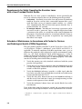
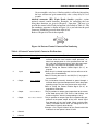
Schedule of Maintenance in Accordance with Center for Devices
and Radiological Health (CDRH) Regulations
This laser product complies with Title 21 of the United States Code of Federal Regulations, Chapter 1, subchapter J, parts 1040.10 and 1040.11, as
applicable. To maintain compliance with these regulations, once a year, or
whenever the product has been subjected to adverse environmental conditions (e.g., fire, flood, mechanical shock, spilled solvent, etc.), verify all
features of the product identified on the Excelsior CDRH Radiation Control Drawing (Figure 2-6 on page page 2-9) function properly. Also, make
sure that all warning labels remain firmly attached.
1. Verify that opening any safety interlock switch used with the system
prevents laser operation.
2. Verify the laser can only be turned on when the EMISSION keyswitch
is in the ON position, and that the key can only be removed when the
switch is in the STBY position.
3. Verify the EMISSION indicator(s) provides a visible signal when the
laser emits accessible laser radiation that exceeds the accessible master
system emission limits for Class I.*
4. Verify the time delay between turn-on of the EMISSION indicator(s)
and the start of laser emission; it must give enough warning to allow
action to avoid exposure to laser radiation.
5. Verify the mechanical shutter closes and actually blocks laser radiation emission.
If any of the above items fail to operate as noted and you cannot correct the
error, please call your Spectra-Physics service representative for assistance.
*
2-8
0.39 µW for continuous-wave operation where output is limited from 400 nm to
1400 nm.
Laser Safety
Excelsior Radiation Safety Control Drawings
Refer to the warning labels on page 2-10.
6
1
VISIBLE
AND/OR
INVISIBLE
LASER
RADIATION
IS EMITTED
FROM
THIS
APERTURE
0420-790 0
AVOID EXPOSURE
2
Las ersVIEW; CA
ysic s
MT.
013
94039-7
AVOID EXPOSURE
E
OR MOR
BERS
ONE
UNDERENT NUM
5
PAT
TURED
0,41
U.S.
UFAC
5,87
NTS:
T IS MAN
PATE
7,
PRODUCOWING
2,17
THIS
FOLL
4,87
OF THE
VISIBLE
AND/OR
INVISIBLE
LASER
RADIATION
IS EMITTED
FROM
THIS
APERTURE
0420-790 0
-Ph
7013
BOX
Spe ctra
OFFICE
POST
3
ION
DIAT
R RA SS 3B LASER
LASE
W,
CLA
4,75
6,00
3,
Vie
ysics
untain
, Mo
tra-Ph
Spec lla Avenue
T
PRODUC
,
500m
BEAM
ER <
POW
RE TO
PUT
473 nm
EXPOSU CW OUT
M
AVOID
532 nm,
MAXIMU ELENGTH
WAV
1335
Be
Terra
ED IN
TUR
FAC
MANU
P/N
MFG
Laser
beam
JAPAN
w, CA
H/YEA
MONT
. 940
43
R
-011
0
A150
S/N
7
8
4
Emission
Indicator
5
Emission
On/Off Keyswitch
EMISSION
POWER
ENABLE
STABLE
STBY
SERVICE
ON
EMISSION
CONT
EMISSION
EXT
INT
PWR CONT
EXT
INT
ARRANTY
VO
ID IF
SEAL IS
POWER
ON
W
OFF
3
AC Power
Indicator
Enable
("Laser Ready")
Indicator
Internal/External
Emission Control Switch
AC Power
Internal/External
On/Off Switch Power Control Switch
Remote Safety
Interlock Connector
FUSE
1A
External Control
Cable Connector
5
Spectra-Physics
1335 Terra Bella Avenue, Mountain View, CA.
REMOTE
94043
MANUFACTURED IN JAPAN
CONT
MFG P/N
MONTH/YEAR
S/N
A150-0110
Fuse
LASER
AC POWER
100-240V, 50/60Hz
6
7
Figure 2-6: Excelsior Radiation Control Drawings
2-9
Excelsior Diode-Pumped CW Lasers
ID IF SEA
B
IS
N
W
ROKE
VISIBLE AND/OR
INVISIBLE LASER RADIATION
IS EMITTED FROM THIS APERTURE
VO
L
A
ARR NTY
Excelsior Warning Labels
0420-790 0
AVOID EXPOSURE
Warranty
Seal (3)
CE Aperture
Label (2)
Aperture Label,
Laser Head (1)
VISIBLE AND/OR INVISIBLE
LASER RADIATION
VISIBLE AND/OR INVISIBLE
LASER RADIATION
AVOID EYE OR SKIN EXPOSURE TO
DIRECT OR SCATTERED RADIATION
AVOID EYE OR SKIN EXPOSURE TO
DIRECT OR SCATTERED RADIATION
CLASS 3B LASER PRODUCT
CLASS 4 LASER PRODUCT
473, 505, 515, 532, 542, 561, 594 NM WAVELENGTH
MAXIMUM OUTPUT POWER 500 mW
1064 NM WAVELENGTH
MAXIMUM OUTPUT POWER 1.5 W
CE Danger
Label (4)
Spectra-Physics
3635 Peterson Way, Santa Clara, CA 95054
MANUFACTURED IN JAPAN
MFG P/N
S/N
MONTH/YEAR
COMPLIES WITH 21 CFR 1040.10 AND 1040.11
A150-0110
Serial Number
Label (5)
Spectra-Physics
3635 Peterson Way, Santa Clara, CA 95054
THIS PRODUCT IS MANUFACTURED UNDER ONE OR MORE
OF THE FOLLOWING PATENTS: U.S. PATENT NUMBERS
4,756,003
CE Certification
Label (6)
WEEE
Label (7)
Figure 2-7: Excelsior Warning Labels
2-10
4,872,177
5,870,415
Patent
Label (8)
7,189,703
Laser Safety
Label Translations
For safety, the following translations are provided for non-English speaking personnel. The number in parenthesis in the first column corresponds to
the label number listed on the previous page.
Table 2-2: Label Translations
Label No.
French
German
Spanish
Dutch
Aperture
Label
(1)
Ouverture Laser Exposition Dangereuse - Un rayonnement laser visible et/
ou invisible est émis
par cette ouverture.
Austritt von sichtbarer und unsichtbarer Laserstrahlung!
Bestrahlung vermeiden!
Por esta abertura se
emite radiación láser
visible e invisible;
evite la exposición.
Vanuit dit apertuur
wordt zichtbare en
onzichtbare laserstraling geemitteerd!
Vermijd blootstelling!
CE
Danger
Label
(4)
Rayonnement laser
Exposition Dangereuse, Appareil a
laser de Classe 3b.
Puissance maximum 500 mW,
Longueur d'onde
473, 505, 515, 532,
542, 561, 594 nm
Laserstrahlung
Bestrahlung vermeiden.
Laser Klasse 3b.
Maximale Ausgangsleistung
500 mW
Wellenlänge 473,
505, 515, 532, 542,
561, 594 nm
Radiación láser
Evite la exposición,
Producto láser Clase
3b.
Potencia máxima
500 mW
Longitud de onda:
473, 505, 515, 532,
542, 561, 594 nm
Laser-straling
Vermijd blootstelling!
Klasse 3b laser
produkt.
Max. output vermogen 500 mW,
Golflengtebereik
473, 505, 515, 532,
542, 561, 594 nm
CE
Danger
Label
(4)
Rayonnement laser
Exposition Dangereuse, Appareil a
laser de Classe 4.
Puissance maximum 1.5 W,
Longueur d'onde
1064 nm
Laserstrahlung
Bestrahlung vermeiden.
Laser Klasse 4.
Maximale Ausgangsleistung 1.5 W
Wellenlänge 473,
1064 nm
Radiación láser
Evite la exposición,
Producto láser Clase
4.
Potencia máxima
1.5 W
Longitud de onda:
1064 nm
Laser-straling
Vermijd blootstelling!
Klasse 4 laser
produkt.
Max. output vermogen 1.5 W,
Golflengtebereik
1064 nm
Patent
Label
(8)
Ce produit est fabriqué sous l’un ou
plusieurs des brevets suivants des
Etats Unis:
Dieses Produkt
wurde unter Verwendung einer oder
mehrerer der folgenden US-Patente
hergestellt:
Este producto esta
fabricado con una o
más de las siguientes
patentes de los Estados Unidos:
Dit product is gefabriceerd met een of
meer van de volgende USA patenten:
2-11
Excelsior Diode-Pumped CW Lasers
Waste Electrical and Electronic Equipment Recycling Label
To Our Customers in the European Union:
As the volume of electronics goods placed into commerce continues to
grow, the European Union is taking measures to regulate the disposal of
waste from electrical and electronic equipment. Toward that end, the European Parliament has issued a directive instructing European Union member
states to adopt legislation concerning the reduction, recovery, re-use and
recycling of waste electrical and electronic equipment (WEEE).
In accordance with this directive, the accompanying product has been
marked with the WEEE symbol. See Label 7 on page 2-10.
The purpose of the symbol is to designate that, at the end of its useful life,
the accompanying product should not be disposed of as normal municipal
waste, but should instead be transported to a collection facility that will
ensure the proper recovery and recycling of the product's components. The
symbol also signifies that this product was placed on the market after
13 August, 2005. At this time, regulations for the disposal of waste electrical and electronic equipment vary within the member states of the European Union. Please contact a Newport / Spectra-Physics representative for
information concerning the proper disposal of this product.
2-12
Laser Safety
Sources for Additional Information
Laser Safety Standards
Safe Use of Lasers (Z136.1)
American National Standards Institute (ANSI)
25 West 43rd Street, 4th Floor
New York, NY 10036
Tel: (212) 642-4900
Occupational Safety and Health Administration (Osha Standard, 01-05001-pub8-1.7
U. S. Department of Labor
200 Constitution Avenue N. W., Room N3647
Washington, DC 20210
Tel: (202) 693-1999
Internet: http://www.osha.gov
A Guide for Control of Laser Hazards, 4th Edition, Publication #0165
American Conference of Governmental and
Industrial Hygienists (ACGIH)
1330 Kemper Meadow Drive
Cincinnati, OH 45240
Tel: (513) 742-2020
Internet: http://www.acgih.org/home.htm
Laser Institute of America
13501 Ingenuity Drive, Suite 128
Orlando, FL 32826
Tel: (800) 345-2737
Internet: http://www.laserinstitute.org
International Electrotechnical Commission
Journal of the European Communities
IEC 60825-1 Safety of Laser Products — Part 1: Equipment classification,
requirements and user’s guide
Tel: +41 22-919-0211 Fax: +41 22-919-0300
Internet: http://www.iec.ch
Cenelec
35, Rue de Stassartstraat
B-1050 Brussels, Belgium
Tel: +32 2 519 68 71
Internet: http://www.cenelec.eu
Document Center, Inc.
111 Industrial Road, Suite 9
Belmont, CA 94002
Tel: (650) 591-7600
Internet: http://www.document-center.com
2-13
Excelsior Diode-Pumped CW Lasers
Equipment and Training
Laser Safety Guide
Laser Institute of America
13501 Ingenuity Drive, Suite 128
Orlando, FL 32826
Tel: (800) 34LASER
Internet: http://www.laserinstitute.org
Laser Focus World Buyer's Guide
Laser Focus World
Pennwell Publishing
98 Spit Rock Road
Nashua, NH 03062
Tel: (603) 891-0123
Internet: http//:pennwell.365media.com/laser focus world/search.html
Photonics Spectra Buyer's Guide
Photonics Spectra
Laurin Publications
Berkshire Common
PO Box 4949
Pittsfield, MA 01202-4949
Tel: (413) 499-0514
Internet: http://www.photonics.com
2-14
Chapter 3
System Description
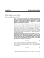
A Brief Review of Laser Theory
Emission and Absorption of Light1
Laser is an acronym derived from Light Amplification by Stimulated
Emission of Radiation. Because the laser is an oscillating amplifier of light,
and because its output comprises photons that are identical in phase and
direction, it is unique among light sources. Its output beam is singularly
directional, monochromatic, and coherent.
Radiant emission and absorption take place within the arrangement of the
electrons in atoms or molecules. Each electron occupies a distinct orbital
that represents the probability of finding the electron at a given position
relative to the nucleus. The energy of an electron is determined by the
orbital that it occupies and the over-all energy of an atom—its energy level
depends on the distribution of electrons throughout the available orbitals.
Each atom has an array of energy levels: the level with the lowest possible
energy is called the ground state, and higher energy levels are called
excited states. If an atom is in its ground state, it will stay there until it is
excited by external forces.
Movement of an electron from one energy level to another—a transition—
happens when the atom either absorbs or emits energy. Transitions in both
directions can occur as a result of interaction with a photon of light. Consider a transition from a lower level whose energy content is E1 to a higher
one with energy E2. It will only occur if the energy of the incident photon
matches the energy difference between levels, i.e.,
hν = E2 – E1
[1]
where h is Planck’s constant and ν is the frequency of the photon.
Likewise, when an atom excited to E2 decays to E1, it loses energy equal to
E2 – E1. The atom may decay spontaneously, emitting a photon with energy
hν and frequency
E –E
2
1
ν = -----------------
[2]
h
1
“Light” will be used to describe the portion of the electromagnetic spectrum from the
infrared to the ultraviolet.
3-1
Excelsior Diode-Pumped CW Lasers
Spontaneous decay can also occur without emission of a photon. An atom
excited to E2 can also be stimulated to decay to E1 by absorbing a photon of
frequency ν, then emitting a pair of photons that are identical to the incident one in phase, frequency, and direction. This is known as stimulated
emission. By contrast, spontaneous emission produces photons that have
no directional or phase relationship with one another.
A laser is designed to take advantage of both stimulated and spontaneous
emission and absorption as well, using them to create conditions favorable
for light amplification. The following paragraphs describe these conditions.
Population Inversion
A material in thermal equilibrium has most of its atoms or molecules in
their ground state. As a result, the rate of absorption of incident light at all
frequencies exceeds that of emission.
If enough light at the correct frequency ν is supplied, electrons in a lower
energy level will absorb light energy and shift to an upper level until the
populations of two levels are equal, N1 = N2. For transition between two levels, N2 can never exceed N1 because every upward transition is matched by
one in the opposite direction. However, if three or more energy levels are
involved in the transition, a population inversion can occur where N2 > N1.
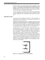
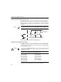
A model four-level laser transition scheme is depicted in Figure 3-1. A
photon of frequency ν1 excites—or “pumps”—an atom from E1 to E4. If the
E4 to E3 transition probability is greater than that of E4 to E1, and if the lifetime of an atom at E4 is short, the atom will decay almost immediately to E3.
If E3 is metastable, i.e., electrons occupy it for a relatively long time, the
population will grow rapidly as excited electrons cascade from above.
The E3 electron will eventually decay to E2, emitting a photon of frequency
ν2. Finally, if E2 is unstable, its electrons will rapidly return to the ground
state, E1, keeping the population of E2 small and reducing the rate of
absorption of ν2. In this way the population of E3 is kept large and that of E2
remains low, thus establishing a population inversion between E3 and E2.
Under these conditions, light is amplified as it passes through the material,
which is now a gain medium.
E4
E3
ν2
ν1
E2
E1
Figure 3-1: A Typical Four-level Transition Scheme
3-2
System Description
Resonant Optical Cavity and Cavity Modes
Most laser materials must be placed in a resonant optical cavity to achieve
useful levels of amplified light. This cavity is typically two mirrors placed
facing each other to form a resonator that reflects light back and forth
through the gain material placed between them. Both resonator mirrors are
coated to reflect the laser wavelength (thus containing it within the cavity)
while transmitting all others (thus removing them from the cavity).
As the reflected light passes through the gain material, stimulated emission
produces two photons. The two photons are trapped in the resonator and
are reflected through the gain to become four, four become eight, and the
numbers continue to increase geometrically until an equilibrium is reached
where the excitation rate and emission rate of the gain medium are equal.
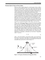
The light in the resonator forms standing waves with frequencies that
depend on the resonator design. Standing wave frequencies that are amplified in the gain material form the circulating light in the cavity. This is the
energy that is transmitted through the output coupler as the laser beam.
There is one standing wave pattern, or cavity mode, that has the simplest
possible form, termed TEM00. TEM00 operation results from choosing the
mirror curvatures and the shape and pumping geometry of the laser material so that gain is confined along the central axis of the material. (This is
further discussed in the section “Diode-Pumped Laser Design” below.)
The TEM00 mode appears brightest in the center and attenuates smoothly
toward the edges of the beam. The spectral content of the light in this mode
arises from the standing waves formed along the axis of the cavity, with
frequencies determined by the separation between the resonator mirrors.
The difference in frequency (Δf) between any two of these “longitudinal
modes” is given by
Δf
c
2nl
= ----------
[3]
where c is the speed of light, n is the refractive index, and l is the distance
between the cavity mirrors. The number of such longitudinal modes in the
laser output is determined by the number of such modes that fall under the
bandwidth of the gain material as shown in Figure 3-2.
C
2L
Gain
Longitudinal
Modes
Gain
Envelope
~ 6-10 GHz
FWHM Point
Frequency (ν)
Figure 3-2: Frequency Distribution of Longitudinal Modes
3-3
Excelsior Diode-Pumped CW Lasers
Single Longitudinal Mode Operation
Some laser applications benefit from a beam with only a single longitudinal mode. From equation 3 it can be seen that reducing the separation
between the resonator mirrors will increase the frequency spacing of the
longitudinal modes and sometimes enable only a single mode to remain
within the gain bandwidth of the laser material. Often however the gain
bandwidth is so large that the mirror separation would have to be impractically short to result in only a single mode remaining. Although the Excelsior lasers are very small, they still produce numerous longitudinal modes
due to the broad gain bandwidth of the neodymium-based crystals.
A variety of means exist to eliminate all but one longitudinal mode in such
a case, including the insertion of an etalon into the resonant cavity. An etalon is type of resonator and, in its simplest form, is just a thin, flat piece of
glass resembling a microscope slide. Placed intracavity, the mode separation of this thin element will limit the modes allowed to resonate.
Nd3+ as a Laser Medium
The output of one laser can be used to excite or “pump” the gain medium
of another laser, e.g., a diode laser can be used to pump a solid-state laser.
The Excelsior lasers use a diode laser to pump Nd3+ ions added to either a
crystal of yttrium vanadate (Nd:YVO4) or yttrium aluminum garnet
(Nd:YAG).
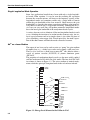
The properties of neodymium-doped crystals are the most widely studied
and best understood of all solid-state laser media. The four-level Nd:YAG
ion scheme is shown in Figure 3-3. The active medium is ionized neodymium, which has principle absorption bands in the red and near infrared.
Pump
Bands
20
18
16
4F
3/2
14
12
8
6
4I15/2
4
4I13/2
2
4I11/2
0
Laser
Transition
4F
3/2
10
4I9/2
11502 cm-1 R2
11414 R1
Laser 4F3/2
Transition
~6000 cm-1
4F3/2
~4000 cm-1
4F3/2
4F3/2
Ground Level
2526
2473
2146
2111
2029
2001
848
311
197
134
0
Figure 3-3: Energy Level Scheme for the Nd Ion in YAG
3-4
System Description
The electrons in the neodymium ions are very efficient at absorbing the
diode laser light, which excites them to the “pump bands” shown in the figure. The excited electrons quickly drop to the 4F 3⁄ 2 level, the upper level of
the lasing transition, where they remain for a relatively long time.
The most probable laser transition is to the 4I 1 ⁄ 2 state, which emits photons
at 1064 nm. Because electrons in that state quickly relax to the ground
state, the population of this state remains low. Hence it is easy to build a
population inversion where the number of electrons in the higher energy
level exceeds the number in the lower level.
There are several different laser transitions in neodymium that start from
the same upper state. These transitions compete for the same population of
electrons, and, if left to themselves, the 1064 nm transition will dominate.
The blue Excelsior lasers employ vanadate (Nd:YVO4) crystals to produce
the 1064 nm wavelength for doubling to 532 nm. Vanadate is a popular
solid-state laser material for small- to medium-power solid-state lasers due
to its low threshold for lasing, along with its large cross section for stimulated emission.
Neodymium can be made to lase at other wavelengths, at 946 nm in particular. This 946 nm transition has a lower gain and a higher threshold than
the 1064 nm transition. When lasing at this wavelength is desired, it can be
achieved by choosing the proper wavelength-selective coatings for the resonator mirrors. Such coatings transmit a high percentage of any 1064 nm
light that might be present, thus decreasing the rate of stimulated emission
for this wavelength and allowing the 946 nm transition to lase.
The 946 nm transition is referred to as “quasi three level” because the
lower laser level lies so close to the 4I 9⁄ 2 ground state. Despite this small
difference in energy, the lower laser level still empties quickly enough to
allow CW operation for this wavelength. However, the small difference in
energy from the ground state does mean that the material will “self-absorb”
at the lasing wavelength.
Self-absorption is a parasitic effect in which the laser light is absorbed by
the laser crystal itself. The lower laser level for the quasi three level transition in vanadate is significantly populated by electrons thermally excited
from the ground state, resulting in absorption of the 946 nm light as the
electrons then make the reverse transition to the upper laser level. Nd:YAG
exhibits the same effect, but thermal population of the lower laser level is
less, so the blue Excelsior lasers employ YAG crystals to produce the
946 nm wavelength for doubling to 473 nm. Self-absorption can also be
reduced somewhat by carefully engineering the diode pump design.
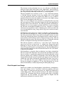
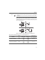
Diode-Pumped Laser Design
Diode lasers combine very high brightness, high efficiency, monochromaticity and compact size in a near-ideal source for pumping solid-state
lasers. Figure 3-4 shows the emission spectra of a diode laser compared to
a black body source. The near-perfect overlap of the diode laser output
with the Nd3+ absorption band ensures that the pump light is efficiently
coupled into the laser medium. Any pump light not coupled into the
medium must ultimately be removed as heat.
3-5
a
Nd3+ Absorption
Excelsior Diode-Pumped CW Lasers
0.5
0.7
0.8
0.9
Wavelength (μm)
Emission Intensity
b
0.6
Black Body
Source (3000°K)
Diode Laser
Pump Wavelength
0.5
0.6
0.7
0.8
0.9
Wavelength (μm)
Figure 3-4: Nd3+ absorption spectra compared to emission spectra of a
Black Body Source (a) and a Diode Laser (b).
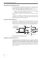
One of the key elements in optimizing the efficiency of a solid-state laser is
maximizing the overlap of the regions of the active medium excited by the
pumping source and the active medium occupied by the laser mode. The
maximization of this overlap is often called mode matching, and in most
applications, TEM00 is the laser mode that is most desired. A longitudinal
pumping geometry provides this sort of optimal mode match.
Longitudinal pumping allows the diode laser output to be focused on a volume in the active medium that best matches the radius of the TEM00 mode.
In general, the TEM00 mode radius is chosen to be as small as possible to
minimize the solid-state laser threshold. Figure 3-5 shows a schematic of a
mode-matching design of this type.
Diode Laser Mode Volume
TEM00 Mode Volume
Gain Region
Figure 3-5: Mode Matching
3-6
Lasing Medium
System Description
Frequency Doubling
In the Excelsior, the infrared output from a neodymium-based laser crystal
is converted to visible light through frequency doubling (also called “second harmonic generation”) in a nonlinear crystal. Frequency doubling
occurs when an intense laser beam enters a nonlinear crystal and generates
a second beam at half the incident wavelength. The blue Excelsior lasers
use a lithium triborate (LBO) crystal as the doubling medium; the green
lasers use a potassium titanyl phosphate (KTP) crystal.
Phase matching is a requirement of nonlinear optics to achieve an efficient
conversion of the fundamental incident light to a new wavelength. To produce any significant output at the new wavelength, the fundamental light
wave and the converted light wave must stay in phase over a sufficient
length in the nonlinear material to allow the conversion to take place.
In most nonlinear materials, however, the indices of refraction at the two
wavelengths will be significantly different, causing the two waves to
become rapidly out of phase unless special techniques are employed. One
such technique takes advantage of the birefringence of nonlinear crystals.
The indexes of refraction of the two light waves can be made to match
exactly if the direction of propagation and the polarization orientation of
the beams within the crystal are carefully controlled. This technique is
referred to as “critical phase matching.” LBO and KTP are nonlinear crystals that lend themselves well to this technique.
The high nonlinear coefficient of KTP has made it historically a very popular material for conversion of lower power 1064 nm infrared lasers to green
wavelengths. KTP can be fabricated in a specialized structure that keeps
the infrared and green beams in an approximate phase-matched condition
over a longer distance than in a typical bulk crystal.
Although LBO has a comparatively smaller nonlinear coefficient, it produces no spatial “walk-off” of the fundamental and second harmonic
beams. This favors a long interaction length for higher gain. Consequently
LBO has subtle advantages that provide superior conversion efficiency of
CW infrared laser light to blue wavelengths.
The second harmonic power (P2ω) produced by frequency doubling is
given by:
2
2 2
d eff P ω l [ φ ]
[4]
P2ω ∝ -------------------------A
where deff is the effective nonlinear coefficient, Pω is the fundamental input
power, l is the effective crystal length, [φ] is a phase-matching factor, and
A is the cross-sectional area of the beam in the crystal.
The important point to note from equation 4 is that the second harmonic
output is dependent upon the square of the fundamental peak power. High
conversion efficiencies can therefore be achieved by placing the doubling
crystal within the laser resonator itself (called “intracavity frequency doubling”) to take advantage of the high circulating intensity. This is the optical design used in the Excelsior.
3-7
Excelsior Diode-Pumped CW Lasers
The Excelsior Lasers
Table 1-1 and Table 1-2 list the various Excelsior laser models. The power
supply/controller provides electrical power, control and monitoring signals
to the laser head. Output power on most Excelsior lasers models can be
varied from 50 to 100% using an external control signal connected to an
interface on the power supply. A few, however, are design for operation at
constant power only.
The Excelsior Laser Head
The Excelsior laser head provides maximum reliability with minimum
complexity and size. The inherent operation is so stable and the output so
quiet that no adjustments are needed for normal operation.
Laser Cavity Design
The Excelsior uses a compact linear cavity for convenient end-pumping of
the laser crystal.
Note
The diode pump laser in the Excelsior laser head is sometimes referred
to simply as the “diode” in this manual, e.g., the “diode current.”
The infrared light generated by the laser crystal is intracavity frequency
doubled to produce either green or blue output; that is, the output of a vanadate crystal at 1064 nm is doubled to 532 nm in the green lasers, and the
output of a YAG crystal at 946 nm is doubled to 473 nm in the blue laser.
A dichroic output coupler transmits a fraction of the doubled light out of
the resonator while confining the rest of the doubled light and virtually all
of the infrared beam inside the laser head.
The infrared pump power of the diode laser is mode-matched in the laser
crystal. This, together with the design of the resonator optics, results in
TEM00 output. The lasers also operate in single longitudinal mode, except
for the lowest power green model, which has multiple longitudinal mode
output (refer to the tables of specifications at the end of this chapter).
Single longitudinal mode operation is achieved by inserting an etalon in the
intracavity space to broaden the spacing of the longitudinal modes beyond
the bandwidth of the laser gain so that only one mode at a time fits within
the gain spectrum.
The Excelsior laser head includes an output telescope assembly that
expands and collimates the beam before it exits the laser head. Refer to the
tables of specifications for exact details. (Some models of the Excelsior
produced for integration into the optical train of an OEM master system are
available without collimation. If interested, contact Spectra-Physics for
additional information.)
All models of the Excelsior include an internal detector to measure output
power. The detector is part of a servo-loop that maintains constant laser
output power over the lifetime of the device by adjusting the current of the
diode pump laser.
3-8
System Description
Mechanical and Thermal Design
The laser resonator is machined from a solid piece of brass for exceptional
thermal and mechanical stability. The waste heat produced by the diode
pump laser (typically less than 2 W) is removed from the laser head by
thermal conduction through the baseplate. The laser crystal is set to a stable
operating temperature of about 45°C by a thermo-electric cooler (TEC)
located in the head beneath the laser cavity.
The mechanical design of the miniature laser head allows for mounting it
using precision alignment pins. Together with the excellent stability and
boresight specifications of the Excelsior, this facilitates both the design of
the optical train of the application as well as the replacement of the laser
head when the diode pump laser eventually reaches its end-of-life condition.
The Excelsior Power Supply/Controller
Power for the laser, as well as monitoring and control capability, is provided by one of two small, separate power supply/control units. A standard
15-pin D-sub connector is used for the LASER connector on the ExcelsiorPS-XC-CDRH model, while a 26-pin SDR connector is used on the Excelsior-PS-CDRH model.
The Excelsior power supply provides output signals proportional to laser
output power and diode laser pump current, as well as an alarm for the
diode lifetime and a status signal that can be used to control an external
laser emission indicator. These features are all available through the CONTrol interface on the back of the Excelsior power supply.
The safety circuit of the Excelsior, accessed through the 2-pin REMOTE
connector on the back of the power supply, must be closed in order for the
laser to operate. An interlock jumper plug (Figure 3-6) is provided with the
system to allow the laser to operate when an optional interlock safety
switch (e.g., a switch across a laboratory door) is not employed.
Figure 3-6: REMOTE Interlock Jumper Plug
The power supply contains two main components: a switching power supply and a control pc board. The switching power supply provides +5 Vdc to
the control pc board with a maximum drive current of 5 A or 8 A (depending on model). The control pc board supplies low-noise, regulated DC current to the laser head to drive the diode laser and a thermo-electric cooler.
3-9
Excelsior Diode-Pumped CW Lasers
Specifications
This page and the next one are to be discarded and replaced with the 11 x
17 Specifications fold-out page.
3-10
System Description
3-11
Excelsior Diode-Pumped CW Lasers
Outline Drawings
4.3
110
0.4
11
CLOSE
3.4
87
1.1
28
OPEN
1.7
42
Beam Exit
Aperture
Beam
Height
0.75
19
1.5
39
1.44
36,5
4.3
110
Dimensions given in
inches
mm
0.22
5,5
4.0
101
0.18
4,5
0.33
8,5
1.2
30
2.0
50
3.7
93
4-R 3,75
Ø3 +0.01 Wx4L
0
Ø3 +0.01
0
4-R 2
Figure 3-7: Outline Drawing of the Excelsior DPSS-CDRH Laser Head
3-12
1.0
25
1.5
37
1.7
42
System Description
CLOSE
4.53
115
OPEN
1.97
50
0.18
4
0.83
21
0.28
7.0
3.98
101
1.71
43.5
0.75
19
Dimensions given in
0.14
3.5
4.25
108
0.22
5.5
0.18
4
inches
mm
Ø3 +0.01 Wx4L
0
Ø3 +0.01
0
4–Ø3.5
1.71
43.5
Figure 3-8: Outline Drawing of the Excelsior DPSS-XC-CDRH Laser Head
3-13
Excelsior Diode-Pumped CW Lasers
5.5
140
EMISSION
STBY
POWER
ENABLE
STABLE
SERVICE
ON
EMISSION
POWER
ON
2.75
70
OFF
Dimensions given in inches
mm
6.5
165
(PS-CDRH) or
7.1
180
(PS-XC-CDRH)
Figure 3-9: Outline Drawing of Excelsior Power Supply/Controller
3-14
0.25
6
Chapter 4
Controls, Indicators and Connections
This section defines the user controls, indicators and connections of the
Excelsior laser head and power supply. Chapter 6 describes how to use
these features to operate the laser.
The Excelsior Laser Head
Shutter
AVOID EXPOSU
RE
VISIB
INVISI
IS EMITT
LE AND
LASER
EDBLE
FROM
/OR
THISRADIA
TION
APER
TURE
0420-790
0
Laser Beam
LASER
RADIA
TION
DUCT
ER PRO
3B LAS
CLASS
W,
BEAM ,
< 500m
RE TO
POWER
EXPOSU
946 nm
AVOID
OUTPUT
473 nm,
M CW
MAXIMU
1064 nm;
532 nm,
NGTH
WAVELE
Figure 4-1: The Standard Excelsior Laser Head
Controls
Shutter—is opened and closed by means of the lever on the top of the
laser head near the output end. The shutter is open when it is pushed to the
left (when looking in the direction of the laser beam) to the OPEN position.
Shutter
OPEN
OPEN
CLOSE
CLOSE
Shutter
Standard Laser Head
XC Laser Head
Figure 4-2: Shutter “Open/Close” Designations
4-1
Excelsior Diode-Pumped CW Lasers
Connections
LASER cable connector (rear panel, not shown)—provides connection
for a control cable (supplied) that provides control signals and power to the
laser head from the power supply/controller. One of two types of connectors is present:
• the Excelsior-CDRH laser head has a 26-pin SDR connector.
• the Excelsior-XC-CDRH laser head has an HD 15-pin D-sub connector.
Excelsior Power Supply/Controller
Front Panel
EMISSION
STBY
POWER
ENABLE
STABLE
SERVICE
ON
EMISSION
POWER
ON
OFF
Figure 4-3: The Power Supply/Controller Front Panel
Two power supplies are available for the Excelsior series lasers: one for the
standard laser head and one for the extended laser head. They appear to be
the same, but some functions differ slightly. These differences are noted
below under “standard” and “extended.”
Controls
EMISSION keyswitch — provides interlock safety to prevent unauthorized
personnel from using the laser when the key is turned to the STBY position
and removed.
If the POWER switch has been turned on and the ENABLE indicator is on
and the EMISSION CONTROL switch has been set to INT, turning on the
EMISSION keyswitch will turn on the laser (following a safety delay of 3 to
5 seconds). If the shutter is open, the laser will emit a laser beam.
Optionally, if the EMISSION CONTROL switch has been set to EXT, the
Excelsior laser can be turned on by applying a suitable control signal to
Pin 2 of the CONTrol connector on the back of the power supply. However,
the POWER switch must already be on and EMISSION keyswitch must be in
the STBY position prior to sending the On signal. See Chapter 6 for details
of this method of operation.
4-2
Controls, Indicators and Connections
switch — turns on power to the power supply. When
switched on and the internal circuits respond properly, the POWER indicator on the front panel turns on. Once on, the laser head resonator begins to
warm to its operating temperature, which typically takes between 2 to 5
minutes. The ENABLE indicator turns on when warm-up is complete.
POWER ON/OFF
Indicators
POWER indicator—turns on when the POWER switch is turned on and the
internal circuits respond properly.
ENABLE indicator—turns on when the laser resonator has warmed to its
operating temperature, which is about 2 to 5 minutes after the POWER
switch has been turned on. Once this light is on, the laser can be turned on.
STABLE indicator—turns on when laser power reaches its set value and
becomes stable, and it remains on as long as laser power is stable. The laser
typically reaches its set operating power and becomes stable about 10 seconds (DPSS-CDRH) or 30 seconds (DPSS-XC-CDRH) after turning on the
EMISSION keyswitch or after an On command has been received at Pin 2 of
the CONTrol interface connector.
SERVICE indicator—turns on when diode laser current rises to 95% of the
factory-set current limit. This indicates that a replacement laser head is
needed (although not immediately). Laser emission will be stable until the
current reaches the 100% limit. When the limit is exceeded, emission will
continue, but power may decrease and/or fluctuate.
EMISSION indicator—turns on when the EMISSION keyswitch is turned on
(see the prerequisites for turning on the keyswitch above), and emission
occurs 3 to 5 seconds later. (Note: this indicator does not blink during the
delay as it does on some other laser systems).
If the REMOTE interlock circuit is opened (see the description below), laser
emission stops immediately and this indicator turns off. If the REMOTE
interlock switch is then closed again, one of the following actions occur:
• On a standard Class 3b laser or extended cavity (XC) laser, if the keyswitch is still in the ON position, the EMISSION indicator turns on
again immediately and the laser turns on again following a safety
delay of 3 to 5 seconds.
• On a standard Class 4 laser, if the keyswitch is still in the ON position,
the keyswitch must first be turned off, then back on again in order to
resume operation. After it is turned back on, the EMISSION indicator
turns on again and the laser will turn on again after a safety delay of 3
to 5 seconds.
Pin 1 of the CONTrol connector can be used to control an external emission
indicator. See Chapter 6 for an example of a circuit used for this purpose.
4-3
Excelsior Diode-Pumped CW Lasers
Back Panel
FUSE
1A
REMOTE
CONT
LASER
AC POWER
100-240V, 50/60Hz
Figure 4-4: The Power Supply/Controller Back Panel
Connections
connector—provides attachment for an IEC power cable. The
cable provides ac power to the system and accepts service from 47 to 63 Hz
at 90 to 264 Vac.
FUSE holder—holds a 5.2 mm x 20 mm, fast-acting cartridge fuse. The
required fuse is:
• Excelsior-PS-CDRH
250 V, 1 A
• Excelsior-PS-XC-CDRH
250 V, 2 A
REMOTE interlock connector (2-pin)—provides attachment for a usersupplied safety switch. These contacts must be shorted together before the
laser will operate. A defeating interlock jumper plug (Figure 4-5) is
installed at the factory to permit operation without a safety switch.
AC POWER
Figure 4-5: REMOTE Interlock Jumper Plug
To turn on the laser again following an interlock fault (when the two contacts were opened), close the contacts again (resolve the fault issue) and do
one of the following:
On a standard Class 3b Laser, if the keyswitch is still in the ON position, the laser will turn on again automatically after a safety delay of 3
to 5 seconds.
On a standard Class 4 laser, the keyswitch must be turned off, then
back on again in order to resume operation following a safety delay of
3 to 5 seconds.
4-4
Controls, Indicators and Connections
On an extended cavity laser, if the keyswitch is still in the ON position,
the laser will turn on again automatically after a safety delay of 3 to 5
seconds.
CONTrol connector (HD 15-pin D-sub, female)—provides various
optional external control functions. Examples for controlling the laser
using these functions are given in Chapter 6, “Operation.” The user is to
provide the control cable. Each pin function is described in Table 4-1. The
pin numbering sequence is shown in Figure 4-6 as you look into the panel
connector. Numbering proceeds from right to left.
Refer to Chapter 6 for circuit descriptions.
5
1
15
11
Figure 4-6: External Control Connector Pin Numbering
Table 4-1: External Control (CONT) Connector Pin Functions
Pin
Type
Description
Function
1
Output
Laser STABLE
This pin becomes internally shorted to ground through a
transistor when the laser reaches stable operation, i.e.,
when laser output power is at the specified level and “stable,” and laser head temperature is within the proper operating range. The shutter can be opened at this time.
Refer to “Using the External Stable Signal (Pin 1)” on
page 6-3.
2
Input
Laser ON/OFF
When this pin is shorted to ground, the laser will turn on following a 3 to 5 second delay.
Refer to “Turning the Laser On and Off (Pin 2)” on page 6-2
for instructions.
3
Output
Laser ENABLE
This pin becomes internally shorted to ground through a
transistor when laser head temperature is within the proper
operating range. The laser may be turned on at this time.
Refer to “Using the External Enable Signal (Pin 3)” on
page 6-3 for instructions.
4
Output
Current Monitor
This pin provides an output signal proportional to the current
of the diode pump laser. The scale is 100 mV/Amp, and
maximum signal is 160 mV (corresponding to 1.6 A).
5
Output
Laser Power Monitor
This pin provides an output signal that is approximately proportional to the power output of the laser. Actual signal
level depends on the laser model. When nominal power
(100%) is emitted from the laser, the voltage on Pin 5 is
about 100 mV (typically 96 to 98 mV).
Example: a Pin 5 signal of 50 mV for the Excelsior-532-150
indicates that laser power is about 75 mW.
6
Ground
7
Ground
4-5
Excelsior Diode-Pumped CW Lasers
Table 4-1: External Control (CONT) Connector Pin Functions
Pin
Type
Description
Function
8
Input
9
Output
+12 Vdc
This pin provides +12 Vdc @ 20 mA (max). This output can
be used for external power control or for driving an external
LED for indicating status.
10
Output
SERVICE Alarm
Indicates the diode pump laser in the laser head is nearing
its end of life. To employ this “open collector” alarm, refer to
“Using the Service Alarm Signal (Pin 10)” on page 6-4.
11
Ground
12
Ground
13
N/A or
Output
Reserved or
Thermistor Alarm
Must be open on an Excelsior-PS-CDRH) or it provides a
thermistor alarm on a Excelsior-PS-XC-CDRH). For the latter, it indicates that the thermistor circuit inside the laser
head has opened. To employ this “open collector” alarm,
refer to “Using the Thermistor Alarm (Pin 13)” on page 6-6.
14
N/A
Reserved
Must be open
15
N/A
Reserved
Must be open
External Power Control This pin is used to vary the output power of the lasers listed
in Table 6-1.
Refer to “Changing Laser Output Power (Pin 8)” on page 6-4
for instructions.
LASER connector — provides power, control and monitoring to and from
the laser head. This connector mates to the 1.8 m (6 ft) control cable, which
restricts the laser head to the CDRH maximum distance from the EMISSION
indicator on the power supply. Two types of connectors are used:
• a 26-pin 3M SDR connector is used on the Excelsior-PS-CDRH power
supply.
• a standard 15-pin D-sub connector is used on the Excelsior-PS-XCCDRH power supply.
Controls on the Power Supply Side Panel
PWR CONT
INT
EMISSION CONT
EXT
INT
W
N
4-6
ROKE
Figure 4-7: The Power Supply Side Panel
B
IS
A
ARR NTY
ID IF SEA
L
VO
EXT
Controls, Indicators and Connections
switch—allows Excelsior output power to be controlled
remotely. Refer to the description of the CONTrol connector on page 4-5
above and “Changing Laser Output Power (Pin 8)” on page 6-4.
EMISSION CONT switch—allows the Excelsior laser to be turned on and
off remotely via Pin 2 of the CONTrol connector. Refer to the CONTrol connector on page 4-5 and “Turning the Laser On and Off (Pin 2)” on page 62.
PWR CONT
4-7
Excelsior Diode-Pumped CW Lasers
4-8
Chapter 5
Installation
Detailed descriptions of the signals and connectors for the Excelsior laser
system are provided in Chapter 4, “Controls, Indicators, and Connections.”
Examples of how to operate the laser using either the controls on the power
supply/controller itself or via external signals applied to the CONTrol interface connector on the power supply are given in Chapter 6, “Operation.”
A control cable provides control, power, monitoring and diagnostic signals
between the laser head and the power supply. Depending on the system,
either a 15-pin to 15-pin cable is provided (Standard CDRH systems) or a
26-pin to 26-pin cable is provided (XC CDRH systems). The cable is
attached between the LASER connector on the back of the power supply
and the connector on the laser head. If external control is desired, the user
must provide a cable with a 15-pin D-sub connector on one end for connection to the CONTrol interface connector on the back of the power supply.
Power
The power supply provides low-noise, regulated, high current to the laser
head to drive the diode laser. The power supply is auto-ranging and
requires a single-phase ac electrical source of 90–264 Vac at 47 to 63 Hz.
The Excelsior-PS-CDRH requires a maximum of 40 W of ac power and is
capable of providing 13 W of dc power to a standard laser head. The Excelsior-PS-XC-CDRH requires a maximum of 70 W of ac power and is capable of providing 28 W of dc power to an XC laser head.
Thermal Management
Management of the heat load produced by the laser is critical to maintaining its specified output. The laser head must be mounted on a heatsink
capable of maintaining its baseplate temperature below 50°C but greater
than 10°C. The diode pump laser in the laser head will produce several
watts of waste heat that must be removed through the baseplate by the heatsink (see Figure 5-1).
Cooler ambient temperatures for the environment of the laser will make the
job of dissipating waste heat through the baseplate easier (see Figure 5-2).
The Excelsior power supply produces a significant current load to power
the thermo-electric cooler (TEC) inside the laser head. Consequently, a
reliable means to remove waste heat from the power supply must be provided as well. The relatively large heatsink on the side of the power supply
is sufficient to remove heat from the inside of the housing as long as the
ambient temperature meets the following specifications.
5-1
Excelsior Diode-Pumped CW Lasers
Ambient temperature (operating):
10°C–40°C (< 80% RH) for the power supply and laser head.
Baseplate of laser head (operating):
10°C–50°C for the laser head belonging to Groups A and C
10°C–45°C for the laser head belonging to Group B
Table 5-1: Heat Dissipation, Laser Head
Standard Laser Head
XC Laser Head
Group A
Group B
Group C
Excelsior-473-50-CDRH
Excelsior-505-20-CDRH
Excelsior-532-50/100-CDRH
Excelsior-532-150/200-CDRH
Excelsior-515-50-CDRH
Excelsior-532-20M-CDRH
Excelsior-542-50-CDRH
Excelsior-532-300-CDRH
Excelsior-561-20/50/75-CDRH
Excelsior-561-100/150-CDRH
Excelsior-1064-500/800-CDRH
Excelsior-594-30/50-CDRH
Heat Dissipation at Laser (W)
Excelsior-473-10-CDRH
30
C
25
20
15
B
10
A
5
0
0
10
20
30
40
50
60
70
Laser Head Baseplate Temperature
(Operational, °C)
Maximum Permissible Heatsink
Thermal Impedance (°C/W)
Figure 5-1: Heat Dissipation of the Laser Head
8
A
6
B
4
2
C
0
0
10
20
30
40
50
60
Ambient Temperature (°C)
Figure 5-2: Maximum Permissible Heatsink Thermal Impedance
5-2
Installation
Installing the Hardware
Mounting the Laser Head
Follow standard practice to mount the laser head on a suitable heatsink that
meets the requirements described in the preceding section.
Refer to the outline drawings at the end of Chapter 3 for mounting hole
locations. Holes and slots are provided for precision alignment pins. (Note
that slots are provided only on Excelsior-DPSS-CDRH lasers.) Position the
laser head in the desired location, then use four M3 (or 4-40) screws and
washers to mount the laser head using the mounting holes/slots on the front
and back of the baseplate; or use four smaller screws and washers to use
the slots on the sides of the baseplate.
The boresight specifications are with respect to the axis of the precision
alignment hole and slot. Note that the beam height is located 19 mm (about
¾ in.) above the baseplate mounting surface.
The heatsink surface for the laser head must be flat to 0.050 mm or better.
The laser head can withstand a small amount of vibration and still perform
to specification. Refer to the specifications listed at the end of Chapter 3
for more information.
Mounting the Power Supply
The power supply is a standard table-top device. Refer to the outline drawing in Figure 3-9 on page 3-14.
Connecting the Cables
1.
2.
Connect the 1.8 m (6 ft) laser head cable provided between the connector on the laser head and the LASER connector on the back of the
power supply.
If desired, wire a remote safety switch (or series of switches) to the 2pin REMOTE connector on the back of the power supply. These 2 pins
must be shorted in order for the laser to operate. A jumper is supplied
to short the pins if an optional safety switch is not employed. The
jumper can be modified (jumper removed) for use as a connector for a
safety switch.
Figure 5-3: REMOTE Connector Jumper Plug
3.
4.
Connect the power supply ac power cable to your utility power source.
The external control interface (through the CONTrol connector on the
back of the power supply) allows the laser to be turned on and off from
a remote signal source connected to Pin 2. If a remote control signal is
5-3
Excelsior Diode-Pumped CW Lasers
to be used, the EMISSION CONT switch on the side of the power supply
must be set to EXT. If it is not to be used, this switch must be set to INT.
5. The external control interface also allows the output power of some
laser models to be controlled externally using a remote signal source at
Pin 8. (A list of compatible laser heads is provided in Table 5-2.) If
laser power is to be controlled externally, the PWR CONT switch on the
side of the power supply must be set to EXT. Otherwise, this switch
should be left in the INT position for continuous, maximum power output.
If external control of the laser is desired, proceed to connect the CONTrol
connector on the power supply.
Table 5-2: Lasers capable of variable output power1, 2
Excelsior-473-10
Excelsior-473-50
Excelsior-505-20
Excelsior-515-50
Excelsior-532M-20
Excelsior-532-50
Excelsior-532-100
Excelsior-532-150
Excelsior-532-200
1
2
Excelsior-542-50
Excelsior-561-25
Excelsior-561-50
Excelsior-561-100
Excelsior-561-150
Excelsior-594-50
Excelsior-1064-500
Excelsior-1064-800
These lasers will only operate at constant full power when the PWR CONTROL switch is
set to INT.
These lasers meet specified parameters only at 100% laser output power.
External Control Connector
The following directions are provided if you intend to operate the laser
remotely using the CONTrol interface connector.
1. Set the EMISSION CONT and/or the PWR CONT switches to EXT, as
appropriate. The PWR CONT switch should be set to EXT for remote
control only for the lasers listed in Table 5-2. Otherwise, this switch
should be set to INT for all lasers for continuous, maximum output
power.
2. Connect a cable with a 15-pin D-sub connector to the CONTrol connector. The pin numbering sequence is shown in Figure 5-4 (as you
look at the power supply connector). Numbers proceed from right to
left. Pin 2 provides on/off control. Pin 8 provides power output control. Use one of the ground pins (Pins 6, 7, 11 or 12) for reference
(Ground). Pin descriptions are given in Table 5-3. Directions for operating the laser remotely are provided in Chapter 6.
5
1
15
11
Figure 5-4: External CONTrol Interface Connector Pin Numbering
5-4
Installation
Table 5-3: External Control (CONT) Connector Pin Functions
Pin
Type
Description
Function
1
Output
Laser STABLE
This pin becomes internally shorted to ground through a
transistor when the laser reaches stable operation, i.e.,
when laser output power is at the specified level and “stable,” and laser head temperature is within the proper operating range. The shutter can be opened at this time.
Refer to “Using the External Stable Signal (Pin 1)” on
page 6-3.
2
Input
Laser ON/OFF
When this pin is shorted to ground, the laser will turn on following a 3 to 5 second delay.
Refer to “Turning the Laser On and Off (Pin 2)” on page 6-2
for instructions.
3
Output
Laser ENABLE
This pin becomes internally shorted to ground through a
transistor when laser head temperature is within the proper
operating range. The laser may be turned on at this time.
Refer to “Using the External Enable Signal (Pin 3)” on
page 6-3 for instructions.
4
Output
Current Monitor
This pin provides an output signal proportional to the current
of the diode pump laser. The scale is 100 mV/Amp, and
maximum signal is 160 mV (corresponding to 1.6 A).
5
Output
Laser Power Monitor
This pin provides an output signal that is approximately proportional to the power output of the laser. Actual signal
level depends on the laser model. When nominal power
(100%) is emitted from the laser, the voltage on Pin 5 is
about 100 mV (typically 96 to 98 mV).
Example: a Pin 5 signal of 50 mV for the Excelsior-532-150
indicates that laser power is about 75 mW.
6
Ground
7
Ground
8
Input
9
Output
+12 Vdc
This pin provides +12 Vdc @ 20 mA (max). This output can
be used for external power control or for driving an external
LED for indicating status.
10
Output
SERVICE Alarm
Indicates the diode pump laser in the laser head is nearing
its end of life. To employ this “open collector” alarm refer to
“Using the Service Alarm Signal (Pin 10)” on page 6-4.
11
Ground
12
Ground
13
N/A or
Output
Reserved or
Thermistor Alarm
Must be open on an Excelsior-PS-CDRH) or it provides a
thermistor alarm on a Excelsior-PS-XC-CDRH). For the latter, it indicates that the thermistor circuit inside the laser
head has opened. To employ this “open collector” alarm,
refer to “Using the Thermistor Alarm (Pin 13)” on page 6-6.
14
N/A
Reserved
Must be open
15
N/A
Reserved
Must be open
External Power Control This pin is used to vary the output power of the lasers listed
in Table 6-1.
Refer to “Changing Laser Output Power (Pin 8)” on page 6-4
for instructions.
5-5
Excelsior Diode-Pumped CW Lasers
5-6
Chapter 6
Danger!
Laser Radiation
Operation
The Spectra-Physics Excelsior lasers are Class IIIb and Class 4—High
Power Lasers whose beams are, by definition, safety hazards. Take precautions to prevent accidental exposure to both direct and reflected
beams. Diffuse as well as specular beam reflections can cause severe
eye damage.
Because the infrared (IR) beam of the 1064 nm lasers is invisible, it is
especially dangerous. Infrared radiation passes easily through the cornea of the eye, which, when focussed on the retina, can cause instantaneous and permanent damage!
Always wear proper eye protection when working on the laser and follow the safety precautions in Chapter 2, “Laser Safety.” Refer to the
product model number label for wavelength (nm).
Detailed descriptions of signals and connectors are given in Chapter 4,
“Controls, Indicators, and Connections.”
Operating the Laser from the Power Supply
The simplest way to operate the laser is to allow it to run at constant (maximum) power and to use the EMISSION keyswitch on the power supply to
turn the laser on and off.
Turning the Laser On and Off
1.
2.
3.
Note
Always start the laser with the shutter closed. Also be sure that the
beam will be terminated by the target, a power detector or other suitable beam block.
Turn on the POWER switch. The POWER indicator will illuminate. The
laser head will take 2 to 5 minutes to reach operating temperature, at
which time the ENABLE indicator will turn on.
Turn on the EMISSION keyswitch. The EMISSION indicator will illuminate and, after a CDRH delay of 3 to 5 seconds, the Excelsior will produce laser radiation.
If the EMISSION keyswitch is turned on before the ENABLE indicator
turns on, the laser will not start. If this happens, turn off the keyswitch
and turn on the keyswitch. Then turn on the keyswitch on again.
6-1
Excelsior Diode-Pumped CW Lasers
4.
5.
6.
Wait a few seconds for laser output power to stabilize. Once stabilized,
the STABLE indicator will illuminate.
Open the shutter to unblock the laser output beam.
To turn the laser off, turn the EMISSION keyswitch to STBY, remove
the key and close the shutter. This is the recommended “off” condition
when the laser is going to be used frequently—it saves warm-up time.
If the laser is not to be used for an extended period (e.g., when turned
off over night), also turn off the ac POWER switch or utility power.
Operating the Laser Using the External Control Interface
All laser functions can be controlled by applying remote analog signals to
the CONTrol interface connector on the back of the power supply. Table 53 on page 5-5 defines the function of each pin of that connector. Note that
ground pins for the CONTrol connector are Pins 6, 7, 10 and 11.
Before using a remote source to control the laser, the EMISSION CONTROL
switch on the side of the power supply must be set to EXT (Figure 4-7).
Then, leaving the EMISSION keyswitch set to STBY, apply ac power to the
power supply and turn on the POWER switch. The following discussions
assume that this has already been done. To return the system to internal
control and maximum output power, set the EMISSION CONTROL switch
back to INT.
Turning the Laser On and Off (Pin 2)
The laser can only be turned on after the resonator has reached normal operating temperature and the ENABLE signal, Pin 3, is pulled low (see “Using
the External Enable Signal (Pin 3)” on page 6-3). When the laser is stable,
the STABLE signal, Pin 1, is pulled low (see “Using the External Stable Signal (Pin 1)” on page 6-3.)
Internal
+5 V
Laser
On/Off
Pin 2
Input
Gnd
Gnd
Power Supply
External Circuit
Figure 6-1: Example of a typical laser On/Off control circuit.
Use a switching circuit similar to that shown in Figure 6-1 to turn the laser
on and off. When the external transistor connected to Pin 2 is turned on,
thus pulling Pin 2 low, the diode pump laser turns on and emission occurs.
After the laser has received this On command, it is ready to perform to
specifications after 3 to 5 seconds. Note: the external transistor in the figure
above can be replaced by a simple mechanical switch or relay.
6-2
Operation
Using the External Enable Signal (Pin 3)
When laser head temperature is within normal operating range (i.e., when
the resonator has stabilized), an internal transistor connected to Pin 3 turns
on, thus pulling Pin 3 low.
Pin 3
+5 V
“Enable”
Indicator
Gnd
Gnd
Power Supply
“Enable” Signal
External Circuit
Figure 6-2: Example Circuit for a Remote Enable Signal/Indicator
A circuit similar to that shown in Figure 6-2 can be used to signal a remote
controller that the laser is ready to be turned on, or it can be used to turn a
remote Enable indicator on and off as shown in the example. The Pin 3
transistor can sink up to 20 mA maximum.
Note
An On signal from the EMISSION keyswitch or from a TTL-low signal
applied to Pin 2 will only be accepted when ENABLE is active low.
Using the External Stable Signal (Pin 1)
When laser head temperature has reached normal operating range and the
laser has been turned on and output power has stabilized, an internal transistor connected to Pin 1 turns on, thus pulling Pin 1 low. This signals the
laser is ready to use following a 3- to 5-second CDRH delay.
Pin 1
+5 V
“Stable” or
“Emission”
Indicator
Gnd
Gnd
Power Supply
“Stable” or
“Emission” Signal
External Circuit
Figure 6-3: Example Circuit for a Remote Stable/Emission Signal/
Indicator
A circuit similar to that shown in Figure 6-3 can be used to signal a remote
controller that the laser is stable and emission has occurred, or it can be
used to turn a remote Enable or Emission indicator on and off. The Pin 3
transistor can sink up to 20 mA maximum.
6-3
Excelsior Diode-Pumped CW Lasers
Using the Service Alarm Signal (Pin 10)
The SERVICE alarm is activated on Pin 10 (the pin is pulled low) when the
diode laser drive current reaches 95% of the factory-set maximum limit.
Figure 6-4 shows an example of a circuit that can be used for monitoring
the SERVICE alarm remotely. The Pin 10 transistor can sink up to 20 mA
maximum.
To allow the laser head to become fully stabile, the Pin 10 signal is disabled for the first 5 minutes after the EMISSION keyswitch is turned on.
Note
+5 V
Service Alarm
Service
Alarm
Indicator
Service Alarm
Signal (active low)
Pin 10
Gnd
Gnd
Power Supply
External Circuit
Figure 6-4: Example or a Service Alarm Circuit
Changing Laser Output Power (Pin 8)
The output power of the lasers listed in Table 6-1 can be varied from 50%
to 100% by varying the voltage on Pin 8 from 0 to 5 V. To implement this,
the PWR CONTROL switch located on the side of the power supply (Figure
4-7) must first be set to EXT.
Be sure the PWR CONTROL switch is set to INT for Excelsior models
NOT listed in Table 6-1; those lasers will not operate if this switch is
mistakenly set to EXT.
Caution!
Table 6-1: Lasers capable of variable output power1, 2
Excelsior-473-10
Excelsior-473-50
Excelsior-505-20
Excelsior-515-50
Excelsior-532M-20
Excelsior-532-50
Excelsior-532-100
Excelsior-532-150
Excelsior-532-200
1
2
6-4
Excelsior-542-50
Excelsior-561-25
Excelsior-561-50
Excelsior-561-100
Excelsior-561-150
Excelsior-594-50
Excelsior-1064-500
Excelsior-1064-800
These lasers will only operate at constant full power when the PWR CONTROL switch is
set to INT.
These lasers meet specified parameters only at 100% laser output power.
Operation
Operating the laser below 50% of its rated power is not recommended.
The full set of Excelsior specifications are guaranteed only at the 100%
power level.
Note
Figure 6-5 shows two simple external circuits for making these adjustments. Table 6-2 lists the recommended parameters for R1 and VR1. Note
that although the input at Pin 8 is shown as 0 to 5 V, this corresponds to 0
to 100% of output power, whereas actual adjustment should only go from
50% to 100% output power.
12 V
Pin 9
R1
Pin 8
Input Impedance
ZIN
VR1
Gnd
External Circuit
Power Supply
R1
Pin 8
Input Impedance
ZIN
Vdc = 12 V
VR1
Gnd
Power Supply
External Circuit
Figure 6-5: Example Circuits for Varying Laser Output Power
Table 6-2: Recommended Parameters for R1 and VR1 in Figure 6-5
Controller
Excelsior–PS–CDRH
Excelsior–PS–XC–CDRH
1
Input
Impedance
ZIN
Value for VR11
Value for R11
Voltage to Pin 8
(Corresponding to
0–100% output power)
18 kΩ
1 kΩ
2 kΩ
5 kΩ
10 kΩ
1.2 kΩ
2.2 kΩ
5.1 kΩ
8.2 kΩ
0V–5V
26 kΩ
1 kΩ
2 kΩ
5 kΩ
10 kΩ
1.2 kΩ
2.4 kΩ
5.6 kΩ
9.1 kΩ
0V–5V
If Vdc in the bottom figure is not 12 V, the resistance of VR1 and R1 should be modified accordingly.
6-5
Excelsior Diode-Pumped CW Lasers
Monitoring Laser Output Power (Pin 5)
Laser output power can be monitored remotely at Pin 5, which provides an
output signal that is approximately proportional to laser output power.
Actual output at Pin 5 depends on laser model. For example:
Excelsior-PS-CDRH: At full output power, the signal is 95 to 100 mV.
Example: a Pin 5 signal of 50 mV for the Excelsior-473-10-CDRH
indicates that laser power has fallen to about 5 mW.
Excelsior-PS-XC-CDRH: At full output power, the signal is approximately 2 V.
In order to avoid affecting the automatic power control circuit inside the
controller, the input impedance of the external circuit should be greater
than 10 k:, preferably greater than 100 k:.
Using the 12 Vdc Output (Pin 9)
Pin 9 provides a 12 Vdc source that can be used with Pin 8 to vary laser
output power (see “Changing Laser Output Power (Pin 8)” on page 6-4).
Figure 6-6 shows a schematic of the 12 Vdc circuit. The impedance ZOUT of
the external user circuit must not draw more than 20 mA total from Pin 9.
+ 12 V
5 V or 12 V
(From external DC
power supply or built-in DC/DC converter
DC power supply)
In
Pin 9
+V out
Output Impedance
ZOUT
Gnd
Com
Out
Gnd
Gnd
– 12V
Power Supply
External Circuit
Figure 6-6: The 12 Vdc Supply Circuit
Using the Thermistor Alarm (Pin 13)
A thermistor inside the laser head is used as part of a circuit to control the
temperature of the laser resonator. When an “open” thermistor occurs, such
as when a wire breaks on the thermistor (from shock and/or vibration), the
thermistor alarm is activated on Pin 13 (the pin goes low). When this
alarm occurs, temperature control and laser emission are terminated. Figure 6-7 shows an example circuit. The Pin 13 transistor can sink up to
20 mA maximum.
6-6
Excelsior Diode-Pumped CW Lasers
6-8
Chapter 7
Danger!
Laser Radiation
Eyewear
Required
Troubleshooting and Service
The Spectra-Physics Excelsior lasers are Class IIIb and Class 4—High
Power Lasers whose beams are, by definition, safety hazards. Take precautions to prevent accidental exposure to both direct and reflected
beams. Diffuse as well as specular beam reflections can cause severe
eye damage.
Because the infrared (IR) beam of the 1064 nm lasers is invisible, it is
especially dangerous. Infrared radiation passes easily through the cornea of the eye, which, when focussed on the retina, can cause instantaneous and permanent damage!
Always wear proper eye protection when working on the laser and follow the safety precautions in Chapter 2, “Laser Safety.” Refer to the
product model number label for wavelength (nm).
Maintenance
The Excelsior laser head requires no routine maintenance. There is no reason to remove the outer cover because there are no user-serviceable parts
inside the laser head. This cover should only be removed by an authorized
service engineer.
To retain a clean intracavity environment, all components are cleaned to
stringent standards prior to assembly and alignment at the factory. The
cover of the laser module inside the laser head is secured and sealed and
should never be opened. Removing the module cover will compromise the
cleanliness of the intracavity space, degrade laser performance and void
the warranty.
Replacing the diode pump laser can only be performed at a Spectra-Physics
facility by someone trained and authorized by Spectra-Physics. Call your
Spectra-Physics service representative when you suspect that the diode
pump laser is at its end of life (e.g., the Service indicator has turned on).
All parts that normally come in contact with laboratory or industrial environments retain surface contamination that can be transferred to optical
components during handling. Indeed, skin oils can be very damaging to
optical surfaces and coatings and can lead to serious degradation problems
under intense laser illumination. It is, therefore, essential that only clean
items come into contact with optical components and to the mechanical
parts immediately surrounding them.
7-1
Excelsior Diode-Pumped CW Lasers
Service Training Programs
Excelsior lasers are designed for hands-off operation. This product does not
require alignment nor routine cleaning of cavity optics. Service is generally
limited to replacing the entire laser head. Spectra-Physics offers service
training programs to train personnel in diagnosing problems.
Troubleshooting
This troubleshooting guide is intended to assist you in identifying some of
the problems that might arise while using the system. For information
about repairing the laser, please call your Spectra-Physics representative. A
list of world-wide service sites is included at the end of this chapter.
Symptom: No laser beam
Possible Causes
Corrective Action
Shutter is closed.
Verify the hand-operated shutter is open (set to the left).
Loose cable connector
Verify that all cables are securely connected.
Improper settings for the
internal/external control
switches
If laser is controlled internally, both the PWR CONTROL and the EMISSION CONTROL switches must be set to INT.
External control
No On signal applied to the
CONT connector
If laser power is controlled externally, the EMISSION CONTROL switch
must be set to EXT.
Pin 2 of the CONT connector must be pulled to ground to turn on the laser.
Improper settings for external power control
If laser power is controlled externally, the PWR CONTROL switch must be
set to EXT. The ac POWER switch and the EMISSION keyswitch must
both be on.
Pin 8 of the CONT connector must receive a suitable input signal for external power control.
Symptom: Low power
Possible Causes
Corrective Action
Incorrect power measurement
Ensure that output power is measured as it leaves the laser head before
the output beam enters any external optical elements.
Shutter is clipping the beam
Verify the hand-operated shutter is fully open.
Loose cable connector
Verify that all cables are securely connected.
Laser is not warmed up
Allow the laser to warm up for at least 5 minutes.
Dirty output window
Clean the laser head output window.
Laser head temperature outside operating range
Measure the temperature of the baseplate. If it is below 10°C or exceeds
50°C (or 45°C for Group B models), verify the ambient temperature is
within the allowable operating range and correct if necessary. Refer to
Table 5-1, Figure 5-1 and Figure 5-2.
Verify the laser head baseplate is properly heat-sinked.
7-2
Troubleshooting and Service
Symptom: Low power
Reflected laser light is destabilizing the laser
Ensure that light reflected from any external optical elements does not
reflect back through the window of the laser head.
Diode pump laser has
reached its end of life
Contact your Spectra-Physics service representative about replacing the
laser head.
Improper settings for internal
power control
For internal power control, the PWR CONTROL switch must be set to INT.
External control
Incorrect settings for external
power control
If the laser power is controlled externally, set the PWR CONTROL switch to
EXT, and provide a stable, low-noise 5 V signal to Pin 8 of the CONT connector.
Do not set the output power level below 50% of the maximum specified output power for your Excelsior laser model.
Incorrect use of external
power control
Only the Excelsior lasers listed in Table 6-1 are designed for external
power control.
If your model is suitable only for internal power control, verify the
PWR CONTROL switch is set to INT.
Symptom: High optical noise
Possible Causes
Corrective Action
Loose cable connector
Verify that all cables are securely connected.
Improper setting for the PWR
CONTROL switch
Verify the PWR CONTROL switch is set to INT.
If laser power is controlled externally, set the PWR CONTROL switch to
EXT, and provide a stable, low-noise 5 V signal to Pin 8 of the CONT connector.
Laser is not warmed up
Allow the laser to warm up for at least 5 minutes.
Laser head temperature is
outside operating range
Measure the temperature of the baseplate. If it is below 10°C or exceeds
50°C (or 45°C for Group B models), verify the ambient temperature is
within the allowable operating range and correct if necessary. Refer to
Table 5-1, Figure 5-1 and Figure 5-2.
Verify the laser head baseplate is properly heat-sinked.
Reflected laser light is destabilizing the laser
Ensure that light reflected from any external optical elements does not
reflect back through the window of the laser head.
Improper ground
Check the grounding of the laser head and the power supply.
Vibration is outside operating
limits
Verify any vibration experienced by the laser head is within operating limits.
External noise source
Verify that there are no strong electromagnetic noise sources near the system. If output power is controlled externally, verify the voltage signal
applied to Pin 8 of the CONT connector is low-noise.
Symptom: Bad transverse mode
Possible Causes
Corrective Action
Improper setting for the PWR
CONTROL switch
Verify the PWR CONTROL switch is set to INT.
If the laser power is controlled externally, set the PWR CONTROL switch to
EXT and provide a stable, low-noise 5 V signal to Pin 8 of the CONT connector.
Laser is not warmed up
Allow the laser to warm up for at least 5 minutes.
Dirty output window
Clean the laser head output window.
7-3
Excelsior Diode-Pumped CW Lasers
Symptom: Bad transverse mode
Laser head temperature is
outside operating range
Measure the temperature of the baseplate. If it is below 10°C or exceeds
50°C (or 45°C for Group B models), verify the ambient temperature is
within the allowable operating range and correct if necessary. Refer to
Table 5-1, Figure 5-1 and Figure 5-2.
Verify the laser head baseplate is properly heat-sinked.
Reflected laser light is destabilizing the laser
Ensure that light reflected from any external optical elements does not
reflect back through the window of the laser head.
Symptom: Output power is unstable
Possible Causes
Corrective Action
Loose cable connector
Verify that all cables are securely connected.
Improper settings for the
PWR CONTROL switch
Verify that the controller PWR CONTROL switch is set to INT.
If laser power is controlled externally, set the PWR CONTROL switch to
EXT and provide a stable, low-noise 5 V signal to Pin 8 of the CONT connector.
Laser is not warmed up
Allow the laser to warm up for at least 5 minutes.
Laser head temperature is
outside operating range
Measure the temperature of the baseplate. If it is below 10°C or exceeds
50°C (or 45°C for Group B models), verify the ambient temperature is
within the allowable operating range and correct if necessary. Refer to
Table 5-1, Figure 5-1 and Figure 5-2.
Verify the laser head baseplate is properly heat-sinked.
Reflected laser light is destabilizing the laser
Ensure that light reflected from any external optical elements does not
reflect back through the window of the laser head.
7-4
Troubleshooting and Service
Replacement Parts
The following is a list of parts that may be purchased to replace broken,
worn-out or misplaced components.
Table 7-1: Replacement Parts
Description
Part Number
Excelsior 10 mW @ 473 nm, single mode
Excelsior-473-10-SLM-CDRH
Excelsior 50 mW @ 473 nm, single mode
Excelsior-473-50-SLM-CDRH
Excelsior 20 mW @ 505 nm, multi mode
Excelsior-505-20-MLM-CDRH
Excelsior 50 mW @ 515 nm, single mode
Excelsior-515-50-SLM-CDRH
Excelsior 20 mW @ 532 nm, multi mode
Excelsior-532-20-MLM-CDRH
Excelsior 50 mW @ 532 nm, single mode
Excelsior-532-50-SLM-CDRH
Excelsior 100 mW @ 532 nm, single mode
Excelsior-532-100-SLM-CDRH
Excelsior 150 mW @ 532 nm, single mode
Excelsior-532-150-SLM-CDRH
Excelsior 200 mW @ 532 nm, single mode
Excelsior-532-200-SLM-CDRH
Excelsior 300 mW @ 532 nm, single mode
Excelsior-532-300-SLM-CDRH
Excelsior 25 mW @ 561 nm, single mode
Excelsior-561-25-SLM-CDRH
Excelsior 50 mW @ 561 nm, single mode
Excelsior-561-50-SLM-CDRH
Excelsior 100 mW @ 561 nm, single mode
Excelsior-561-100-SLM-CDRH
Excelsior 150 mW @ 561 nm, single mode
Excelsior-561-150-SLM-CDRH
Excelsior 50 mW @ 594 nm, multi mode
Excelsior-594-50-MLM-CDRH
Excelsior 500 mW @ 1064 nm, single mode
Excelsior-1064-500-SLM-CDRH
Excelsior 800 mW @ 1064 nm, single mode
Excelsior-1064-800-SLM-CDRH
Excelsior Power Supply for standard laser heads
Excelsior-PS-CDRH
Excelsior Power Supply for extended cavity (XC) laser heads
Excelsior-PS-XC-CDRH
Excelsior Laser Head Cable for standard laser, 1.8 m (6 ft)
Excelsior-Laser-Cable-CDRH
Excelsior Laser Head Cable for extended cavity laser, 1.8 m (6 ft)
Excelsior-Laser-Cable-XC-CDRH
Excelsior Remote Connector
Excelsior-Connector-CDRH
Excelsior Power Supply “Emission” Key
Excelsior-Key-CDRH
7-5
Excelsior Diode-Pumped CW Lasers
Customer Service
At Spectra-Physics, we take great pride in the reliability of our products.
Considerable emphasis has been placed on controlled manufacturing methods and quality control throughout the manufacturing process. Nevertheless, even the finest precision instruments will need occasional service. Our
instruments have excellent service records compared to competitive products, and we strive to provide excellent service to our customers in two
ways: by providing the best equipment for the price and by servicing your
instruments as quickly as possible.
When calling for service inside the United States, dial our toll free number:
1 (800) 456-2552. To phone for service in other countries, refer to “Service
Centers” on page 7-7.
Order replacement parts directly from Spectra-Physics. For assistance of
any kind, contact your sales office or service center. You will need your
model and serial numbers available when you call. To order optional items
or other system components, or for general sales assistance, dial 1 (800)
SPL-LASER in the United States, or 1 (408) 980-4300 from anywhere else.
Warranty
All parts and assemblies manufactured by Spectra-Physics are unconditionally warranted to be free of defects in workmanship and materials for
the period of time listed in the sales contract following delivery of the
equipment to the F.O.B. point.
Liability under this warranty is limited to repairing, replacing, or giving
credit for the purchase price of any equipment that proves defective during
the warranty period, provided prior authorization for such return has been
given by an authorized representative of Spectra-Physics. Spectra-Physics
will provide at its expense all parts and labor and one-way return shipping
of the defective part or instrument (if required). In-warranty repaired or
replaced equipment is warranted only for the remaining portion of the original warranty period applicable to the repaired or replaced equipment.
This warranty also does not apply to equipment or components that, upon
inspection by Spectra-Physics, is found to be defective or unworkable due
to abuse, mishandling, misuse, alteration, negligence, improper installation, unauthorized modification, damage in transit, or other causes beyond
the control of Spectra-Physics.
This warranty is in lieu of all other warranties, expressed or implied, and
does not cover incidental or consequential loss.
Returning the Instrument for Repair
Contact your nearest Spectra-Physics field sales office, service center, or
local distributor for shipping instructions. You are responsible for one-way
shipment of the defective part to Spectra-Physics. Instruments can be
returned only in Spectra-Physics containers. We encourage you to use the
original packing boxes to secure instruments during shipment. If shipping
boxes have been lost or destroyed, we recommend ordering new ones.
7-6
Troubleshooting and Service
Service Centers
Belgium
Telephone:
Fax:
0800-11 257
0800-11 302
China
Newport Corporation
Beijing Representative Office
Room 2305, Building B, Tri-Tower
No. 66 Zhongguancun East Road
Beijing 100080
P. R. China
Telephone:
(86) 10-6254-7746
Fax:
(86) 10-6255-6373
France
MICRO-CONTROLE
Spectra-Physics S.A.
1, rue Jules Guesde - Bât. B
ZI. Bois de l’Epine - BP189
9106 Evry CEDEX, France
Telephone:
+33-1-60-91-68-68
Fax:
+33-1-60-91-68-69
Internet:
[email protected]
Germany and Export Countries*
Newport Spectra-Physics GmbH
Guerickeweg 7
D-64291 Darmstadt, Germany
Telephone:
+49-(0) 06151-708-0
Fax:
+49-(0) 06151-708-217
Internet:
[email protected]
Japan (East)
Spectra-Physics K.K.
4-6-1 Nakameguro Meguro-ku
Tokyo 153-0061, Japan
Telephone:
+81-3-3794-5511
Fax:
+81-3-3794-5510
Internet:
[email protected]
Japan (West)
Spectra-Physics K.K.
Nishi-honmachi Solar Building, 3-1-43 Nishi-honmachi Nishi-ku
Osaka 550-0005, Japan
Telephone:
+81-6-4390-6770
Fax:
+81-6-4390-2760
Internet:
[email protected]
*
And all European and Middle Eastern countries not included on this list.
7-7
Excelsior Diode-Pumped CW Lasers
Netherlands
Newport Spectra-Physics B.V.
Vechtensteinlaan 12-16
3555 XS Utrecht
Netherlands
Telephone:
0900 555 5678
Fax:
0900 555 5679
Internet:
[email protected]
Taiwan
Newport Corporation
Room A, 10F, No. 80, Sec. 1, Jianguo N. Rd.
Zhongshan
District, Taipai City 104, Taiwan (R.O.C.)
Telephone:
+886-2-2508-4977
Fax:
+886-2-2508-0367
Internet:
[email protected]
United Kingdom
Newport Spectra-Physics Ltd-Registered Office
Unit 7, Library Avenue
Harwell Science & Innovation Campus, Didcot.
Oxfordshire, OX11 0SG
Telephone:
+44 1235 432710
Fax:
+44 1235 821045
Internet:
[email protected]
United States and Export Countries*
Spectra-Physics
3635 Peterson Way
Santa Clara, CA 95054-2809
Telephone:
(800) 456-2552 (Service) or
(800) SPL-LASER (Sales) or
(800) 775-5273 (Sales) or
(408) 980-4300 (Operator)
Fax:
(408) 980-6921
e-mail:
[email protected]
[email protected]
Internet:
www.spectra-physics.com
*
7-8
And all non-European or Middle Eastern countries not included on this list.
Notes
Notes-1
Excelsior Diode-Pumped CW Lasers
Notes-2
Notes
Notes-3
Excelsior Diode-Pumped CW Lasers
Notes-4
Notes
Notes-5
Excelsior Diode-Pumped CW Lasers
Notes-6
Report Form for Problems and Solutions
We have provided this form to encourage you to tell us about any difficulties you have experienced in
either using your Spectra-Physics instrument or its manual—problems that did not require a formal
call or letter to our service or marketing departments, but that you feel should be remedied. We are
always interested in improving our products and manuals and we appreciate all suggestions.
Send all instrument related questions to:
Send all manual related questions to:
Spectra Physics
Spectra Physics
A Newport Corporation Brand
A Newport Corporation Brand
Service Manager
Senior Director Product Marketing
3635 Peterson Way
3635 Peterson Way
Santa Clara, CA 95054
Santa Clara, CA 95054
FAX: (408) 980-3584
FAX: (408) 980-7101
Thank you.
From:
Name
Company or Institution
Department
Address
Instrument Model Number
Problem:
Suggested Solution(s):
Serial Number