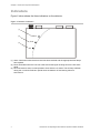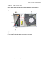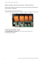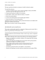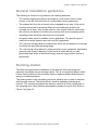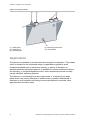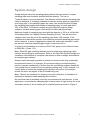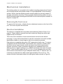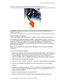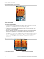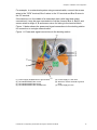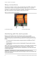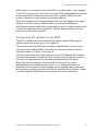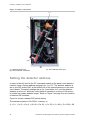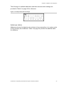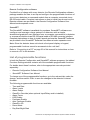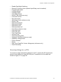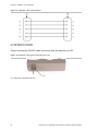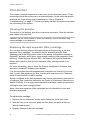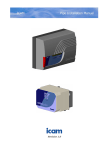
1
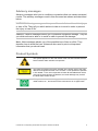
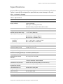
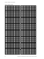
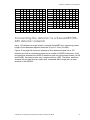
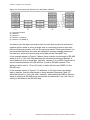
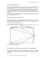
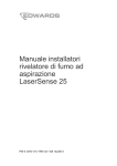
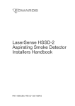
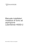
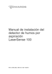
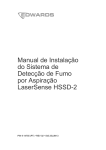
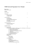
LaserSense 100
Aspirating Smoke
Detection System
Installers Handbook
P/N 9-14567 • REV 01 • DRAFT 00.06
Copyright
Manufacturer
Certification
© 2012 UTC Fire and Security. All rights reserved.
Kidde Products Limited
Unit 2 Blair Way Dawdon
City: Seaham, County Durham
SR7 7PP
United Kingdom
0832
0832-CPD-0982
EN54-20: 2006
Aspirating smoke detectors for fire detection and fire alarm systems
for buildings.
Class A, B and C
Technical data: See INF48029 held by the manufacturer
Contact information
For contact information, see www.utcfireandsecurity.com.
Content
Important information 2
EN 54-20 4
Chapter 1
Product and component descriptions 1
Introduction 2
Available software for the detector 2
Specifications 3
Indicators 4
Inside the detector 5
Removable terminal block connections 6
Chapter 2
Installation and configuration 7
Introduction 8
Antistatic precautions 8
General installation guidelines 9
Docking station 9
Application 10
System design 11
Mechanical installation 16
Relay connections 20
Interfacing with fire alarm panels 20
Setting the detector address 22
Connecting the detector to a SenseNET/RS-485 detector
network 25
Final installation 27
Removing the detector 27
Configuring the detector after installation 27
Connecting to a PC 29
Event log 31
Chapter 3
Commissioning 33
Introduction 34
Precommissioning preparation 34
Commissioning checklist 34
Chapter 4
Troubleshooting 37
Troubleshooting the detector 38
Chapter 5
Maintenance 41
Introduction 42
Diagnostics 43
Index 45
LaserSense 100 Aspirating Smoke Detection System Installers Handbook
i
Important information
Regulatory information
This equipment is Class III as defined in EN 60950 (i.e., this equipment is
designed to operate from Safety Extra Low Voltages and does not generate any
hazardous voltages).
As this equipment is part of a fire detection system, input power should be
supplied from an approved power supply conforming to EN 54-4.
In order for the installation to conform to EN 54-20, pipes must conform at least
to EN 61386-1 Class 1131.
Limitation of liability
To the maximum extent permitted by applicable law, in no event will UTCFS be
liable for any lost profits or business opportunities, loss of use, business
interruption, loss of data, or any other indirect, special, incidental, or
consequential damages under any theory of liability, whether based in contract,
tort, negligence, product liability, or otherwise. Because some jurisdictions do not
allow the exclusion or limitation of liability for consequential or incidental
damages the preceding limitation may not apply to you. In any event the total
liability of UTCFS shall not exceed the purchase price of the product. The
foregoing limitation will apply to the maximum extent permitted by applicable law,
regardless of whether UTCFS has been advised of the possibility of such
damages and regardless of whether any remedy fails of its essential purpose.
Installation in accordance with this manual, applicable codes, and the instructions
of the authority having jurisdiction is mandatory.
While every precaution has been taken during the preparation of this manual to
ensure the accuracy of its contents, UTCFS assumes no responsibility for errors
or omissions.
ii
LaserSense 100 Aspirating Smoke Detection System Installers Handbook
Advisory messages
Advisory messages alert you to conditions or practices that can cause unwanted
results. The advisory messages used in this document are shown and described
below.
WARNING: Warning messages advise you of hazards that could result in injury
or loss of life. They tell you which actions to take or to avoid in order to prevent
the injury or loss of life.
Caution: Caution messages advise you of possible equipment damage. They tell
you which actions to take or to avoid in order to prevent the damage.
Note: Note messages advise you of the possible loss of time or effort. They
describe how to avoid the loss. Notes are also used to point out important
information that you should read.
Product Symbols
This symbol appears on the main board of the unit and indicates that the
board contains static sensitive components.
This label is located on the laser chamber at the bottom right of the open
detector and signifies that the unit is a Class 1 Laser product as specified
in IEC 60825-1. The unit incorporates a Class 3B embedded laser which
must not be removed from the detector, as retinal damage may result if
the laser beam enters the eye.
This symbol indicates the Safety ground studs. These are for grounding
cable screens, etc., and should not be connected to 0V or signal earth.
LaserSense 100 Aspirating Smoke Detection System Installers Handbook
iii
EN 54-20
The installation must be designed using PipeCAD software, which is provided
free on the CD shipped with each detector. After designing the installation
including pipes, endcaps, and sampling holes, enter the detector type. To select
the detector type, select Options, select Calculation options, and then select the
detector from the Type drop-down list.
Select “Options” “Calculate” or click on the calculator icon. The software will
prompt you to choose from “Use set hole sizes” “Best flow balance” and “Max.
permissible transit time.” Select the appropriate option and click “OK”. The results
for each pipe (“View” “Results”) show calculations for each sampling hole on the
pipe with the nearest to the detector at the top of the screen, and the endcap
hole at the bottom.
For EN 54-20 compliance the transport time of the last sampling hole shall be
checked following all installation and proven to be less than or equal to that
determined by PipeCAD.
The classification of each sampling device configuration and associated
sensitivity settings are determined by the column headed “Hole sensitivity %
obs/m” which shows the predicted sensitivity for each hole. For the installation to
comply with EN 54-20 depending on the class of installation, each sampling hole
must be no less sensitive than the following:
Class A: 0.62% obs/m
Class B: 0.62% obs/m
Class C: 0.62% obs/m
The calculation can be further refined by leaving a working detector in the
protected area for at least 24 hours at the intended alarm factor for the
installation (this could be done before or after installation). The detector
sensitivity can be read from the “Sensitivity” figure on the histogram screen of the
Remote software supplied with each detector. Click "Options" and then click
"Calculation options" to open the "Hole calculation options" dialog box. Enter the
sensitivity value obtained from the practical test, and then click OK. The new
calculated value will use the real sensitivity from the practical test.
The PipeCAD software will determine the classification of any used configuration.
Commissioning and periodic system tests must involve smoke tests to verify that
the system performs as expected and enters Fire 1 alarm within the time
determined by PipeCAD from the farthest hole. The detector sensitivity must also
be inspected to ensure it has not radically fallen from the installed figure. If it has
changed for any reason, the new figure must be re-entered into PipeCAD and the
recalculated hole sensitivities must be confirmed to be within the class limits
shown above. The settings of a compliant system should be recorded, as it is
possible by changing certain programmable functions to make the system
noncompliant. If functions are changed, it is recommended that the system is
retested if continuing compliance is in any doubt.
iv
LaserSense 100 Aspirating Smoke Detection System Installers Handbook
Chapter 1
Product and component
descriptions
Summary
This chapter provides descriptions of the detector features, specifications, and
controls and indicators.
Content
Introduction 2
Available software for the detector 2
Specifications 3
Indicators 4
Inside the detector 5
Removable terminal block connections 6
LaserSense 100 Aspirating Smoke Detection System Installers Handbook
1
Chapter 1: Product and component descriptions
Introduction
This detector is a highly sophisticated “next generation” high sensitivity aspirating
smoke detection product that provides all the benefits of air sampling high
sensitivity smoke detection, including very early warning. Designed for easy
installation and commissioning, the detector incorporates a patented “artificial
intelligence” known as ClassiFire, which allows the detector to configure itself to
optimum sensitivity, alarm thresholds, and minimum nuisance alarms for various
environments.
The detector operates by drawing air from a protected space via a supervised
piping network in relatively small areas. The sampled air is passed through a
“dust separator” to remove dust and dirt before entering the laser detection
chamber. State of the art electronics are used to analyse the sampled air and
generate a signal representing the level of smoke present.
ClassiFire intelligence also monitors the detector chamber and dust separator
(filter) for contamination, continually adjusting the appropriate operating
parameters to counteract the negative effects of any contamination. Aspirating
smoke detectors are unique in being able to provide a consistent level of
protection in a very wide range of environments by continuously making minor
adjustments to sensitivity.
The aspirating line of detectors detects “difficult-to-detect” slow growth electrical
overload incipient fires in “difficult” environments.
Available software for the detector
The Remote Configuration and the SenseNET software packages are available
for use with the detector.
•
Remote Configuration software: Provided free of charge with every
detector, this software package enables the user to set up and configure the
programmable functions of one or more detectors or Command Module from
a computer connected via an RS-232 serial cable.
•
SenseNET software: SenseNET software is used to configure and manage a
large network of detectors with a simple, streamlined graphical user interface
from a computer connected to a detector or Command Module via an RS-232
serial cable to RS-485 converter interface.
2
LaserSense 100 Aspirating Smoke Detection System Installers Handbook
Chapter 1: Product and component descriptions
Specifications
Caution: This equipment is only to be used in accordance with this specification.
Failure to operate the equipment as specified may cause damage to the unit,
injury, or property damage.
Table 1: Specifications
Specification
Value
SELV rating (EN 60950)
Class III
Supply Voltage
21.6V to 26.4VDC
PSU Type: conforming to EN 54-4
Electrical safety complies with BS EN 610190-1
Size
300 W x 220 H x 90 D (mm) 11.8 W x 8.6 H x 3.5 D (in.)
Weight
3.8 kg (8.4 lbs.) with docking station
Operating temperature range
−10 to +60ºC (EN54-20)
Operating humidity range
0 to 90% noncondensing
BS EN 61010-1 Pollution degree 1
BS EN 61010-1 Installation Cat. II
Sensitivity range
(%obs/ft.)
(%obs/m)
Min. = 7.62%, Max. = 0.00914% FSD
Min. = 25%, Max. = 0.03% FSD
Maximum sensitivity resolution
0.0015% obs/m (0.00046% obs/ft.)
Detection principle
Laser light scattering mass detection
Particle sensitivity range
0.0003 µm to 10 µm
Current consumption
400 mA
Relay contact rating
500 mA at 30 VDC
Maximum sampling pipe length 100 meters (330 feet) total
Sampling pipe inlets
2
Sampling pipe internal
diameter
3/4 in. (ID) or 27 mm (OD)
Alarm levels
4 (Fire 2, Fire 1, Pre-Alarm and Aux)
1 relay as standard, others available
Chamber service intervals
Greater than 8 years (depending on environment)
Dust separator (filter)
replacement intervals
Greater than 5 years (depending on environment)
Laser lifetime (MTTF)
Greater than 1,000 years
Programming
PC via RS-232 or RS-485
Data bus cable
RS-485 data cable
Data bus length
1.2 km (3/4 mile)
IP rating
IP50
LaserSense 100 Aspirating Smoke Detection System Installers Handbook
3
Chapter 1: Product and component descriptions
Indicators
Figure 1 below shows the three indicators on the detector.
Figure 1: Detector indicators
(1)
Alarm
(2)
(3)
Fault
OK
(1) Alarm: Illuminates when the alarm level has been reached and the appropriate time delays
have expired.
(2) Fault: Illuminates when the unit has a fault and a fault signal is being sent to the fire alarm
panel.
(3) OK: Illuminates to show normal operation when there are no faults. The OK lamp will flash
during the 15-minute FastLearn period when the detector is first learning about its
environment.
4
LaserSense 100 Aspirating Smoke Detection System Installers Handbook
Chapter 1: Product and component descriptions
Inside the detector
Figure 2 below shows the main interior parts of a detector with the cover off:
Figure 2: Detector interior view
(2)
(1)
(5)
(4)
(3)
(1)
(2)
(3)
(4)
(5)
Removable terminal block connections
Filter
RS232 serial port
Detector address DIP switch
Addressable Programmable Interface Card (APIC) or relay card port
LaserSense 100 Aspirating Smoke Detection System Installers Handbook
5
Chapter 1: Product and component descriptions
Removable terminal block connections
Figure 3 below shows the terminal block connections that connect the detector to
other electronic components.
Figure 3: Detector terminal block connections
(3)
(4)
(5)
(2)
(1)
(1)
(2)
(3)
(4)
(5)
6
FAULT relay contacts (Open = FAULT)
FIRE relay contacts (Closed = ALARM)
APIC addressable bus connections for use in conjunction with interface card
RS-485/SenseNET connections
Power supply connections
LaserSense 100 Aspirating Smoke Detection System Installers Handbook
Chapter 2
Installation and
configuration
Summary
This chapter provides information necessary to install and configure the detector
system.
Content
Introduction 8
Antistatic precautions 8
General installation guidelines 9
Docking station 9
Application 10
System design 11
Below or above the ceiling installations 13
Mechanical installation 16
Removing the front cover 16
Electrical installation 16
Relay connections 20
Interfacing with fire alarm panels 20
Connecting the detector to an APIC 21
Setting the detector address 22
Address table 23
Connecting the detector to a SenseNET/RS-485 detector network 25
Final installation 27
Removing the detector 27
Configuring the detector after installation 27
List of programmable functions 28
Connecting to a PC 29
Event log 31
LaserSense 100 Aspirating Smoke Detection System Installers Handbook
7
Chapter 2: Installation and configuration
Introduction
This topic provides information necessary to install the detector system.
To install the detector:
1. Unpack the shipping carton. Ensure that the package contains a CD-ROM,
two ferrite rings, two cable glands, and the unit.
2. Determine the optimum location for the detector.
3. Mount APIC or Relay Card inside the detector, if required.
4. Mount the docking station.
5. Connect the docking station to the sampling pipe network.
6. Mount the detector to the docking station.
Installation should only be done by factory-trained technicians in accordance with
applicable installation requirements.
Note: Power should be turned off during installation.
Antistatic precautions
This system contains static-sensitive components. Always ground yourself with a
proper wrist strap before handling any circuits.
Caution: When handling any electric components or printed circuit boards,
antistatic precautions must be followed. Failure to do so may result in component
damage.
Electro-static discharge can be reduced by adhering to the following guidelines:
•
Always use conductive or antistatic containers for transportation and storage,
if returning any item.
•
Wear a wrist strap while handling devices and ensure that a good ground is
maintained throughout the installation process.
•
Never subject a static sensitive device to sliding movement over an
ungrounded surface and avoid any direct contact with the pins or
connections.
•
Avoid placing sensitive devices onto plastic or vinyl surfaces.
•
Minimise the handling of sensitive devices and printed circuit boards (PCBs).
8
LaserSense 100 Aspirating Smoke Detection System Installers Handbook
Chapter 2: Installation and configuration
General installation guidelines
The following is a brief set of guidelines on installing detectors:
•
The detector should normally be mounted at a level where there is easy
access to the RS-232 serial port for configuration and programming.
•
The exhaust air from the unit must not be impeded in any way. If the unit is
mounted where the air pressure differs from the sampling location (for
example an air duct), then a pipe must be, then a pipe must be routed from
the exhaust port back to the same air pressure zone as the sampling holes.
•
Sampling holes should be free from burrs and swarf.
•
All signal cables must be suitable for the application. The specific type of
cable will normally depend upon the local fire regulations.
•
The unit must not be placed in areas where either the temperature or humidity
is outside the specified operating range.
•
The unit should not be placed in close proximity to any equipment expected to
generate high Radio Frequency levels (such as radio alarms) or units
generating high levels of electrical energy (such as large electric motors or
generators).
Docking station
The basic principle behind installation of the detector is that all wiring and
pipework is installed using a docking station. This is a convenient feature which
means that the detector can be dismounted or replaced without disturbing any
wiring or installed pipework.
The docking station inlet (sampling) ports and exhaust port is used to interface
with the pipe network. The inlet ports are used for aspirating the pipework
network. The exhaust port allows the detector exhaust air to be routed back to
the sampling area, when differing atmospheric pressures require this. Refer to
Figure 4 on page 10.
LaserSense 100 Aspirating Smoke Detection System Installers Handbook
9
Chapter 2: Installation and configuration
Figure 4: Docking station
(1) Cable gland
(2) Exhaust port
(3) Sampling port
(4) Mounting screw holes
(5) Ground stud
Application
The detector is intended to provide small area incipient fire detection. This means
that it is suitable for the substantial range of applications typified by small
compartmentalised rooms, warehouse racking, or pieces of electronic or
electromechanical equipment where it is desirable to achieve individual incipient
fire reporting. In compartmentalised rooms, each compartment would normally
use an individual aspirating detector.
The detector is not intended to protect large areas, or to sample from areas
where there may be any difference in airflow rates or pressure differentials. If
detection in environments conforming to these descriptions is required, other
type detectors should be used.
10
LaserSense 100 Aspirating Smoke Detection System Installers Handbook
Chapter 2: Installation and configuration
System design
Simple designs with short sampling pipes produce the best results. Complex
sampling pipe runs should be avoided with the detector. The use of
T-branch pipes is not recommended. The detector is fitted with two sampling pipe
inlets as standard. It is always preferable to use two shorter pipes as opposed to
one longer pipe. If two sampling pipes are used, care should be taken to keep
the sampling pipe lengths and number of sampling holes on each pipe within
10% of the other. This can be verified using the PipeCAD system design
software. Unused sampling pipe inlets should be fitted with pipe bungs.
Maximum length of sampling pipe used with the detector is 100 m in still air with
25 sampling holes (or Capillary Remote Sampling Points). This will provide a
transport time from the end of the sampling pipe within 120 seconds. If the
protected area has airflow present, the maximum permitted sampling pipe length
will be reduced. In areas or applications where the airflow rate exceeds 1 metre
per second, maximum sampling pipe length is reduced to 40 m.
In order for the installation to conform to EN 54-20, pipes must conform at least
to EN61386-1 Class 1131.
Note: PipeCAD pipe modeling software must be used when designing a pipe
network and verifying its performance. Refer to the PipeCAD System Design and
Installation User Manual or complete instructions on how to design and install an
air sampling pipe network.
Always locate the sampling points in positions to which smoke may reasonably
be expected to travel. For example, do not expect ceiling mounted sampling
points to operate satisfactorily if air flow from air-conditioning systems keeps the
cool smoke from an incipient fire from reaching ceiling level. In this instance, it is
usually better to locate the sampling pipe directly in the airflow (for example,
across the return air register of an air conditioning unit).
Note: There is no substitute for carrying out smoke tests prior to installation of
pipework to indicate suitable sampling point location.
No more than two air handling units may be protected with one detector. In this
application, ensure that the sampling pipe is raised clear of high velocity air in the
immediate vicinity of the air intake grill on standoff posts as shown in Figure 5.
95H
LaserSense 100 Aspirating Smoke Detection System Installers Handbook
11
Chapter 2: Installation and configuration
Figure 5: Air handling unit in vicinity of the detector
(1)
(2)
(3)
(4)
(5)
12
Incorrect
Detector
Sampling pipe
Standoff posts
Correct
(6)
(7)
(8)
(9)
Detector
AHU
Equipment cabinet
Direction of smoke
LaserSense 100 Aspirating Smoke Detection System Installers Handbook
Chapter 2: Installation and configuration
Below or above the ceiling installations
The detector is supplied with a docking station (as shown in Figure 4 on page
10). This allows the detector to sample from areas which may be at different air
pressure from the detector location. Typical uses are for air duct sampling and
allowing the installation of the detector in under-floor or ceiling voids or when
sampling from pieces of computer related equipment. See Figure 6 and Figure 7.
98H
9H
Figure 6: Installation of pipework above ceiling with exposed detector (piped exhaust)
(1)
(2)
(5)
(4)
(3)
(1) Sampling pipe
(2) Sampling hole
(3) Detector
(4) Exhaust pipe
(5) False ceiling
LaserSense 100 Aspirating Smoke Detection System Installers Handbook
13
Chapter 2: Installation and configuration
Figure 7: Installation of pipework above ceiling with detector mounted in ceiling void (no
exhaust piping)
(1) Sampling pipe
(2) Sampling hole
14
(3) Detector
(4) False ceiling
LaserSense 100 Aspirating Smoke Detection System Installers Handbook
Chapter 2: Installation and configuration
Table 2 below contains a list of procedural guidelines for installation of the
detector.
Table 2: Procedural guidelines
Do
Don’t
Ensure that the ClassiFire alarm factor is
appropriately set.
Drop the detector.
Ensure that the power and signal cables are
correctly connected before powering up by use
of cable identifiers or electrical continuity
checks. Incorrect connection could damage the
detector.
Ensure that cable of an appropriate approved
type is used for interconnection.
Place sampling points so that the detector will
be able to detect smoke at the earliest
opportunity.
Ensure that the detector exhaust is in an area
with the same atmospheric pressure as the
sample pipes, either by placing the detector
physically in the protected area or by leading a
pipe from the detector exhaust to the protected
area.
Ensure that the environment of the protected
area is within the environmental operating
parameters of the detector.
Install detectors in damp or exposed areas.
Remove or connect boards when the detector is
powered up.
Connect internal 0 volt terminals to local earth.
Attempt to reuse dust separator (filter)
cartridges once removed.
Attempt to adjust or alter detector settings other
than via the user-programmable functions. Any
attempts to adjust the laser potentiometer are
detectable and will void the warranty on the
product.
Place the detector near high power RF sources.
Place the detector so close to other equipment
that there is insufficient room to access and
change the dust separator (filter) or access the
RS-232 connector.
Close unused pipe inlet ports on the detector to
ensure optimal operation.
Use sampling pipe of less than 27 mm (1 inch)
outside diameter without a suitable 27 mm (1
inch) pipe adapter. It is important that there are
no leaks where the pipe connects to the
detector.
Set the appropriate ClassiFire alarm factor for
the area to be detected.
Use excessive force when fitting sampling pipes
as this may damage the detector.
Set the detector address switches correctly
when used in a network.
Ensure that the detector is properly grounded.
LaserSense 100 Aspirating Smoke Detection System Installers Handbook
15
Chapter 2: Installation and configuration
Mechanical installation
The docking station is connected to the installed sampling pipework and fixed to
the mounting surface using three screws of a type appropriate to the mounting
surface. Ensure that the sampling and/or exhaust pipes are securely seated in
the pipe ports before securing. If using a piped exhaust docking station, be sure
that the sampling and exhaust pipes are fitted into the relevant ports as shown in
Figure 4 on page 10.
104H
105H
Removing the front cover
To remove the front cover, unfasten the six attachment screws on the front of the
unit. The cover may then be removed.
Electrical installation
The detector is supplied with removable terminal blocks (Refer to Figure 3 on
page 6). These may be removed from their sockets by lifting them up at right
angles to the circuit board.
106H
107H
Take note of the orientation of each terminal block and its function before
removing it. It may also be beneficial to mark the connection wires with suitable
identification labels or colored rings to aid in the connection process.
Each detector is supplied with a pair of RF suppression ferrite rings. To ensure
compliance with all relevant EMC requirements, the conductors of each cable
should be wound once around a ferrite as shown here before entering the
relevant connector. Power conductors should be on a separate ferrite, but
different forms of signal conductor (e.g. RS485 and relays) can share the same
ferrite. There should be about 30 mm (1-1/4 in.) of wire between the end of the
ferrite and the terminal block to give adequate stress relief. To achieve this, it is
necessary to strip back the cable screen approximately 130 mm (5 in.). The
screen should be terminated under the cable gland cap as shown in Figure 8.
71H
16
LaserSense 100 Aspirating Smoke Detection System Installers Handbook
Chapter 2: Installation and configuration
Figure 8: Looping relay connection wires around a suppression ferrite
WARNING: Electrocution hazard. All connections should be made with the
power turned off.
Power supply connections
The power supply cable should be the shielded (screened) type and should be
led through the metal cable gland provided, leaving about 35 mm (1-1/4 in.) of
the cable extending from the bottom of the cable gland. Depending on the type of
cable used, it may be necessary to increase the diameter of the cable with
sleeving or insulating tape to ensure that the cable is firmly held when the cable
gland is fully tightened.
Note: It is important to be aware of the orientation of the terminal block before
removing it.
To connect the power supply:
1. Remove the detector front cover, and then detach the power supply terminal
block, located at the top left inside the detector. (Refer to Figure 2 on page 5
for a photograph of the detector with the front cover removed. Refer to
Figure 9 on page 18 for a detailed photograph of the power supply terminals.)
2. Detach the power supply terminal block.
3. Connect 0 V and +24 VDC to the “0V” and “24V” screw terminals respectively.
4. Connect the shielded (screened) wire to the ground stud on the docking
station.
5. Connect a second wire from the “Earth” terminal to the docking station ground
stud. Figure 4 on page 10 shows the location of the ground stud for both
types of docking stations.
109H
10H
6. Connect the ground wires to the ground stud.
7. Replace the terminal block with the same orientation as when removed.
LaserSense 100 Aspirating Smoke Detection System Installers Handbook
17
Chapter 2: Installation and configuration
Figure 9: Detector power supply terminals
Signal connections
To connect the signal wire:
1. Lead a suitable wire type (RS-485 cable 9841, 120 ohm shielded (screened)
twisted pair or equivalent) through the second cable gland.
2. Tighten it into position with approximately 35 mm (1-1/4 inch) of cable from
the bottom of the cable gland.
3. Remove either the three-way terminal block next to the power supply socket
(if connecting the detector to a SenseNET system) or the four-way “Bus”
terminal block (if connecting the detector to an alarm panel in conjunction with
the APIC addressable bus card). Refer to Figure 10 for an illustration of the
terminals and “Setting the detector address” on page 22 for details on
addressing.
1H
Figure 10: APIC address and RS-485/SenseNET terminals
(1)
(1) APIC Address terminal
18
(2)
(2) RS-485 / SenseNET terminals
LaserSense 100 Aspirating Smoke Detection System Installers Handbook
Chapter 2: Installation and configuration
For example, in a networked system using screened cable, connect the screen
wires to the “SCN” terminal, Bus A wires to the “A” terminal and Bus B wires to
the “B” terminal.
If the detector is in the middle of a networked chain (with input and output
connections) it may be more convenient to link the common Bus A, Bus B, and
screen wires to single A, B and screen wires for linking to the terminal block.
Figure 11 below shows the power and signal connections to the docking station
for connection to a single network cable.
Figure 11: Power and signal connections to the docking station
(1)
(2)
(3)
(4)
Power supply shielded wire to ground stud
RS-485/SenseNET Bus A wire
RS-485/SenseNET Bus B wire
RS-485/SenseNET Bus shielded wire
(5) Power supply to +24V wire
(6) Wire from “earth” terminal to ground
stud
(7) Power supply 0V wire
LaserSense 100 Aspirating Smoke Detection System Installers Handbook
19
Chapter 2: Installation and configuration
Relay connections
The detector includes an Alarm relay (corresponding to the FIRE 1 alarm level),
which closes on alarm, and a general Fault relay, which opens on any fault
condition or on power-down (see Figure 12 below). The relays are of the volt-free
type, with a maximum current capacity of 500 mA at 30 VDC.
Figure 12: Fault and Alarm relay contacts
(1)
(1) Fault relay contacts
(2)
(2) Alarm relay contacts
Interfacing with fire alarm panels
Because of the flexible nature of the detector and the many possible
configurations, there are many options for interfacing the detectors to the fire
panel. The detector provides the following methods of interfacing with fire alarm
panels:
•
To conventional fire alarm panels using the detector’s ALARM and FAULT
relay contacts
•
To addressable fire alarm panels via Addressable Programmable Interface
Cards (APICs)
APICs, which can be mounted inside the detector, may simplify installation when
connecting to addressable signaling line circuits (SLC). The APIC used is
completely dependent on the SLC protocol, and therefore, the make and model
of the fire alarm panel.
WARNING: Incompatible APIC panel combinations may result in a nonoperational system which may fail to perform during an event, with resultant loss
of life and/or property.
20
LaserSense 100 Aspirating Smoke Detection System Installers Handbook
Chapter 2: Installation and configuration
APICs plug into a connector on the main PCB via a ribbon cable. Once plugged
in, the SLC in and out are connected to the main PCB addressable bus terminals
and the address DIP switches are set to the SLC address. APICs have two
modes of operation: single address and multiple address.
When the interface is set to single address mode, the card appears at a single
address on the SLC and the detector status is read from that address.
Multi-address mode is used when monitoring the status of multiple detectors with
consecutive addresses from a single SLC. Multiple address mode is normally
only used in the Command Mode.
Connecting the detector to an APIC
The APIC is fitted to the four mounting studs on the detector PCB using the
supplied screws as shown Figure 13 on page 22.
The connections to the Fire Panel are made using the BUS L1 and H1 (bus 1
input and output) and the BUS L2 and H2 (bus 1 input and output) terminal
connectors shown in Figure 10 on page 18.
The only settings that need to be made are on the APIC address DIP switches.
The start loop address is entered on SW1 and the end loop address on SW2. In
the case of a single detector the start and end addresses are the same.
Note: The detector address on the SenseNET loop and the fire panel
addressable protocol address are the same, i.e. no address translation is
performed. Some protocols may not support all the available alarm levels and
fault reporting is usually a general fault with no detailed fault information. Please
consult the specific APIC protocol documentation for more information.
LaserSense 100 Aspirating Smoke Detection System Installers Handbook
21
Chapter 2: Installation and configuration
Figure 13: APIC connections
(1)
(3)
(2)
(1) Mounting studs (4X)
(2) APIC Interface connection
(3) APIC address switch (2x)
Setting the detector address
In order to identify itself to the PC command module or fire panel, each detector
needs to have a unique address ranging from 1 to 127. The detector address is
set on the DIP switch SW1 at the bottom left of the opened detector on the main
circuit board. The switch settings are up for 1 and down for 0, and the detector
address is set as a 7-bit binary code (switch 8 equates to a value of 128 and so
is outside the usable address range). Refer to Figure 2 on page 5 for the location
of detector DIP switches.
16H
17H
Figure 14 shows a sample DIP switch setting.
The address equates to 01100011 in binary, or:
(1 x 1) + (1 x 2) + (0 x 4) + (0 x 8) + (0x 16) + (1 x 32) + (1 x 64) + (0 x 128) = 99
22
LaserSense 100 Aspirating Smoke Detection System Installers Handbook
Chapter 2: Installation and configuration
The full range of available addresses and their relevant switch settings are
provided in Table 3 on page 24 for reference.
19H
120H
Figure 14: Sample DIP switch settings
Address table
Addresses chosen for detectors do not have to be consecutive or in a given order
so long as they are all different. Table 3 on page 24 provides the address table
for detectors.
12H
12H
LaserSense 100 Aspirating Smoke Detection System Installers Handbook
23
Chapter 2: Installation and configuration
Table 3: Address table
Address
1
2
3
4
5
6
7
8
65
1
0
0
0
0
0
1
0
1
1
0
0
0
0
0
0
0
66
0
1
0
0
0
0
1
0
2
0
1
0
0
0
0
0
0
67
1
1
0
0
0
0
1
0
3
1
1
0
0
0
0
0
0
68
0
0
1
0
0
0
1
0
4
0
0
1
0
0
0
0
0
69
1
0
1
0
0
0
1
0
5
1
0
1
0
0
0
0
0
70
0
1
1
0
0
0
1
0
6
0
1
1
0
0
0
0
0
71
1
1
1
0
0
0
1
0
7
1
1
1
0
0
0
0
0
72
0
0
0
1
0
0
1
0
8
0
0
0
1
0
0
0
0
73
1
0
0
1
0
0
1
0
9
1
0
0
1
0
0
0
0
74
0
1
0
1
0
0
1
0
10
0
1
0
1
0
0
0
0
75
1
1
0
1
0
0
1
0
11
1
1
0
1
0
0
0
0
76
0
0
1
1
0
0
1
0
12
0
0
1
1
0
0
0
0
77
1
0
1
1
0
0
1
0
13
1
0
1
1
0
0
0
0
78
0
1
1
1
0
0
1
0
14
0
1
1
1
0
0
0
0
79
1
1
1
1
0
0
1
0
15
1
1
1
1
0
0
0
0
80
0
0
0
0
1
0
1
0
16
0
0
0
0
1
0
0
0
81
1
0
0
0
1
0
1
0
17
1
0
0
0
1
0
0
0
82
0
1
0
0
1
0
1
0
18
0
1
0
0
1
0
0
0
83
1
1
0
0
1
0
1
0
19
1
1
0
0
1
0
0
0
84
0
0
1
0
1
0
1
0
20
0
0
1
0
1
0
0
0
85
1
0
1
0
1
0
1
0
21
1
0
1
0
1
0
0
0
86
0
1
1
0
1
0
1
0
22
0
1
1
0
1
0
0
0
87
1
1
1
0
1
0
1
0
23
1
1
1
0
1
0
0
0
88
0
0
0
1
1
0
1
0
24
0
0
0
1
1
0
0
0
89
1
0
0
1
1
0
1
0
25
1
0
0
1
1
0
0
0
90
0
1
0
1
1
0
1
0
26
0
1
0
1
1
0
0
0
91
1
1
0
1
1
0
1
0
27
1
1
0
1
1
0
0
0
92
0
0
1
1
1
0
1
0
28
0
0
1
1
1
0
0
0
93
1
0
1
1
1
0
1
0
29
1
0
1
1
1
0
0
0
94
0
1
1
1
1
0
1
0
30
0
1
1
1
1
0
0
0
95
1
1
1
1
1
0
1
0
31
1
1
1
1
1
0
0
0
96
0
0
0
0
0
1
1
0
32
0
0
0
0
0
1
0
0
97
1
0
0
0
0
1
1
0
33
1
0
0
0
0
1
0
0
98
0
1
0
0
0
1
1
0
34
0
1
0
0
0
1
0
0
99
1
1
0
0
0
1
1
0
35
1
1
0
0
0
1
0
0
100
0
0
1
0
0
1
1
0
36
0
0
1
0
0
1
0
0
101
1
0
1
0
0
1
1
0
37
1
0
1
0
0
1
0
0
102
0
1
1
0
0
1
1
0
38
0
1
1
0
0
1
0
0
103
1
1
1
0
0
1
1
0
39
1
1
1
0
0
1
0
0
104
0
0
0
1
0
1
1
0
40
0
0
0
1
0
1
0
0
105
1
0
0
1
0
1
1
0
41
1
0
0
1
0
1
0
0
106
0
1
0
1
0
1
1
0
42
0
1
0
1
0
1
0
0
107
1
1
0
1
0
1
1
0
43
1
1
0
1
0
1
0
0
108
0
0
1
1
0
1
1
0
44
0
0
1
1
0
1
0
0
109
1
0
1
1
0
1
1
0
45
1
0
1
1
0
1
0
0
110
0
1
1
1
0
1
1
0
46
0
1
1
1
0
1
0
0
111
1
1
1
1
0
1
1
0
47
1
1
1
1
0
1
0
0
112
0
0
0
0
1
1
1
0
48
0
0
0
0
1
1
0
0
113
1
0
0
0
1
1
1
0
49
1
0
0
0
1
1
0
0
114
0
1
0
0
1
1
1
0
50
0
1
0
0
1
1
0
0
115
1
1
0
0
1
1
1
0
51
1
1
0
0
1
1
0
0
116
0
0
1
0
1
1
1
0
52
0
0
1
0
1
1
0
0
117
1
0
1
0
1
1
1
0
24
LaserSense 100 Aspirating Smoke Detection System Installers Handbook
Chapter 2: Installation and configuration
53
1
0
1
0
1
1
0
0
118
0
1
1
0
1
1
1
0
54
0
1
1
0
1
1
0
0
119
1
1
1
0
1
1
1
0
55
1
1
1
0
1
1
0
0
120
0
0
0
1
1
1
1
0
56
0
0
0
1
1
1
0
0
121
1
0
0
1
1
1
1
0
57
1
0
0
1
1
1
0
0
122
0
1
0
1
1
1
1
0
58
0
1
0
1
1
1
0
0
123
1
1
0
1
1
1
1
0
59
1
1
0
1
1
1
0
0
124
0
0
1
1
1
1
1
0
60
0
0
1
1
1
1
0
0
125
1
0
1
1
1
1
1
0
61
1
0
1
1
1
1
0
0
126
0
1
1
1
1
1
1
0
62
0
1
1
1
1
1
0
0
127
1
1
1
1
1
1
1
0
63
1
1
1
1
1
1
0
0
64
0
0
0
0
0
0
1
0
Connecting the detector to a SenseNET/RS485 detector network
Up to 127 detectors may be linked in a single SenseNET bus, supporting a total
length of wire between adjacent detectors of up to 1.2 km (3/4 mile).
Figure 15 on page 26 shows an example of two detectors linked into a 127detector bus with a command module and a number of HSSD-2 detectors. It will
be noted that whereas the HSSD-2 detectors have two input/output buses (1A/1B
and 2A/2B), this detector has only a single such bus (A/B). Therefore, each bus
terminal has an input and an output wire, compared with a single wire in each
terminal in the HSSD-2.
LaserSense 100 Aspirating Smoke Detection System Installers Handbook
25
Chapter 2: Installation and configuration
Figure 15: Connecting the detector to a SenseNET network
(1)
(2)
(3)
(4)
(5)
Command module
Detector 1
Detector 2
Detector 3 (HSSD-2)
Detector 127 (HSSD-2)
It is easy to join the input and output wires for each bus and screen connection
together and to solder or crimp a single wire or connecting ferrule to each wire
pair so that they are easier to fit into the screw terminals. If this is performed, it is
recommended that bare wire joints be insulated to prevent possible shorting of
the data bus, which will cause a drop-out of data on the SenseNET bus.
In the example shown in Figure 15 above, there could be a total length of RS-485
cable of up to 1.2 km (3/4 mile) between the command module and detector 3,
since these are all on a single bus. However, detector 3 is a HSSD-2 which has a
second communications bus (RS-485 bus 2) and an RS-485 repeater. This
allows a further total of 1.2 km (3/4 mile) of cable until the next HSSD-2 in the
RS-485 loop.
124H
125H
In the example shown in Figure 15, if detectors 4-126 (not shown) are all this
type of detector, then the total length of wiring between Detectors 3 and 127
would be limited to 1.2 km (3/4 mile). However, each additional HSSD-2 detector
wired up using both RS-485 buses would allow an additional1.2 km (3/4 mile) of
cabling to be added to the RS-485 loop.
126H
26
LaserSense 100 Aspirating Smoke Detection System Installers Handbook
Chapter 2: Installation and configuration
Final installation
Once the power and signal connections are made, slide the detector body up into
the docking station and fasten it into position using the M4 pan head screws
provided. Slot the power and signal terminal blocks into the relevant sockets on
the detector PCB (which will only click fully home in the correct orientation).
Lastly, replace the detector cover using the six pan head screws provided. Refer
to Figure 16.
130H
Note: The detector is designed solely for operation with the front cover securely
fitted using all six fixing screws.
Removing the detector
Removing the detector is the reverse of the installation process, leaving the
pipework and wiring connections installed in the docking station (as shown in
Figure 4 on page 10). See Figure 16.
13H
132H
13H
Figure 16: Final installation of the detector
(1) Docking station attachment screws (3X)
(2) Cover attachment screws 6X)
Configuring the detector after installation
The detector programmable functions are accessed using a PC (connected
to the detector) running either the remote configuration software or SenseNET
programs.
LaserSense 100 Aspirating Smoke Detection System Installers Handbook
27
Chapter 2: Installation and configuration
Remote Configuration software
Provided free of charge with every detector, the Remote Configuration software
package enables the user to set up and configure the programmable functions of
one or more detectors or command module from a computer connected via an
RS-232 serial cable. Complete instructions on how to install, launch and use the
Remote software are provided in the Remote Configuration Software User
Manual under separate cover.
SenseNET
The SenseNET software is available for purchase. SenseNET software can
configure and manage a large network of detectors with a simple,
streamlined graphical user interface from a computer connected to a detector
or command module via an RS-232 serial cable or RS-485 converter interface.
Complete instructions on how to install, launch and use the SenseNET software
are provided in the SenseNET Software User Manual under separate cover.
Note: Since the detector does not include a front panel display or keypad,
programmable functions cannot be accessed via the unit itself.
Refer to “Connecting to a PC” on page 29 of this manual for instructions on how
to connect a PC to the detector.
List of programmable functions
In both the Remote Configuration and SenseNET software programs, the tabbed
Functions Settings window contains all of the available programmable functions.
For details about these functions, refer to the appropriate manuals provided
separately:
•
Remote Configuration Software User Manual
•
SenseNET Software User Manual
To change one of the programmable functions, go to the relevant tab, make the
change, and then select <OK> to save the changes to the detector’s internal
firmware.
The following programmable functions are available:
•
•
•
•
•
•
•
•
•
•
•
28
Time and Date
Alarm Levels
Alarm Delays
ClassiFire Override (when optional Input/Relay card is installed)
Alarm Factor
LDD Enable
FastLearn Enable
Auto FastLearn Enable
ClassiFire 3D
Demo Mode
Day Start/Night Start
LaserSense 100 Aspirating Smoke Detection System Installers Handbook
Chapter 2: Installation and configuration
•
•
•
•
•
•
•
•
•
•
•
•
•
•
•
•
•
•
•
•
•
•
•
•
•
•
•
Disable Day/Night Switching
Remote Functions (when optional Input/Relay card is installed)
Programmed Isolate
Latching Alarms
Latching Faults
Cascading Alarms
Device Type (reference only)
Firmware Version
Run-time Hours
Watchdog Count (reference only)
Device Text
Reference Detector
Reference Enable
Reference Level
Reference Back-off
Flow Rate (reference only)
Flow High Limit
Flow Low Limit
Flow Fault Delay
Access Code
Chart Recording Rate
Separator Condition (reference only)
Separator Change Date
Factory Default
Reset
Real Time ClassiFire Viewer Histograms (reference only)
Chart Recording
Connecting to a PC
To connect a single stand-alone detector to a PC, connect the PC’s serial port
directly to the detector’s 9-way RS-232 port. Connections for this cable are
shown in Figure 17 on page 30.
LaserSense 100 Aspirating Smoke Detection System Installers Handbook
29
Chapter 2: Installation and configuration
Figure 17: RS-232 cable connections
(1) 9 pin female “D” connector
(2) 9 pin female “D” connector
Figure 18 shows the RS-232 cable connection from the detector to a PC.
Figure 18: Detector serial port connection for a PC
(1) Serial port connection (to PC)
30
LaserSense 100 Aspirating Smoke Detection System Installers Handbook
Chapter 2: Installation and configuration
Event log
The Event Log is a record of detector events such as faults, alarms and function
changes. It is stored inside an operating detector and is updated whenever an
event occurs. The event log is nonvolatile, which means that it is retained when
the detector is turned off. The last 200 detector events may be stored.
An event is defined as:
•
A change to any programmed function
•
A signal received from an external controller such as the remote software,
APIC or SenseNET
•
A detector output level meeting or exceeding the Pre-Alarm, Aux, Fire 1, or
Fire 2 alarm thresholds
•
A fault condition such as a flow or dust separator (filter) fault
•
A start of day or night operation
•
Demonstration Mode start
•
FastLearn start or stop
•
Power on or off
Events can either be viewed on a PC screen or downloaded to disk by running
the Remote Configuration program.
When the detector event log is full (200 events have been logged) and a new
event occurs, the oldest event in the log is deleted (first-in, first-out).
To download the event log, connect a PC to the detector serial port and run the
Remote software or SenseNET programs. For details, see the Remote
Configuration Software User Manual or the SenseNET Software User Manual.
LaserSense 100 Aspirating Smoke Detection System Installers Handbook
31
Chapter 2: Installation and configuration
32
LaserSense 100 Aspirating Smoke Detection System Installers Handbook
Chapter 3
Commissioning
Summary
This chapter provides information to commission the detection system.
Content
Introduction 34
Precommissioning preparation 34
Commissioning checklist 34
LaserSense 100 Aspirating Smoke Detection System Installers Handbook
33
Chapter 3: Commissioning
Introduction
This chapter covers the commissioning procedures for the detector.
Commissioning strategy initially depends upon the environment in which the
detector is installed. For instance, the test for a computer room (in a relatively
clean environment) would be very different from, say, a flour mill, with a high
level of airborne particulate content.
A widely accepted standard for computer rooms or EDP areas is British Standard
BS6266, equipment overheating at a stage well before combustion. To perform
the test electrically overload a 1‑metre length of PVC insulated wire of 10/0.1mm
gauge for one minute using an appropriate power supply. The detector has two
minutes from the end of the wire burn to give an alarm indication.
For areas with higher levels of background particulate matter testing
methodology would be similar to that of standard point detectors.
Commissioning should only be done by factory-trained technicians in accordance
with applicable standards.
Precommissioning preparation
Commissioning should be performed after all construction has been completed
and cleaned of any lingering post-construction dirt. If ambient monitoring
conditions are recorded before the installation is cleaned up, they may not
accurately reflect actual normal operating conditions that need to be used as
reference data for follow-up maintenance procedures and tests.
Commissioning checklist
The following brief checklist allows quick setup of the detector. This procedure
will be adequate for most standard installations.
To commission the detector:
1. Before powering up the detector, visually check all cabling to ensure correct
connection. If wire identification is not immediately clear (e.g. by use of
different colored wires or wire identification sleeves), an electrical check
should be made.
Caution: Ensure that all wiring connections are checked prior to powering up
the detector. Incorrect wiring of the detector will cause permanent damage to
the detector.
2. Connect the detector to a PC and set the detector address on the DIP
Switches and APIC board (if applicable). Refer to “Signal connections” on
page 18 and “Relay connections” on page 20 for more information.
34
LaserSense 100 Aspirating Smoke Detection System Installers Handbook
Chapter 3: Commissioning
3. Power up the detector.
4. Ensure all detectors in the network area are clear of troubles and alarms (if
applicable).
5. Launch either the Remote Configuration software or SenseNET program on
the computer, enter the access code, and then select the Function Settings
window.
6. Verify that the time and date are correct in the Time and date tab.
7. Set an appropriate alarm factor, as shown in Table 4 below, for the protected
environment in the Alarm levels and delays tab. The detector will
automatically perform FastLearn for the new alarm factor (takes
approximately 15 minutes). The OK indicator on the front panel will begin to
flash. If using Day/Night switching, check that the Day Start and Night Start
times reflect site operations.
15H
152H
8. While the detector is still in FastLearn mode, place a checkmark next to the
Demo mode command at the bottom of the Alarm levels and delays screen.
The detector will enter Demo mode (where it estimates its final sensitivity)
immediately after the FastLearn cycle has finished.
Note: Checking the Demo mode box only puts the detector into Demo mode
while the detector is performing a FastLearn. It has no effect at any other
time.
9. Verify that the FastLearn has concluded (the OK indicator has stopped
flashing). With the detector in demo mode, perform any necessary smoke
tests, ensuring that the detector reacts appropriately, and let the smoke fully
dissipate.
10. Perform another FastLearn, this time NOT putting the detector into demo
mode. Do this by placing a checkmark next to the FastLearn Enable
command in the Alarm levels and delays screen. The OK indicator on the
front panel will begin to flash.
11. The detector will generate no alarms during the 15 minute FastLearn period
and, after this, the detector will operate at a reduced sensitivity for 24 hours
while ClassiFire acclimates to the protected environment and sets up
appropriate day and night sensitivity settings.
12. If desired, exit the remote configuration software or SenseNET software,
power down the PC and remove it from the detector serial port.
Table 4: Suggested settings for ClassiFire alarms
Alarm
factor
Sensitivity
Probability of nuisance
alarm
Suggested protected area
0
Extremely High
Once per year
Semiconductor manufacturing clean room
1
High
Once per 5 years
Computer room
2
High
Once per 10 years
Non-smoking office
3
High
Once per 50 years
Clean factory
LaserSense 100 Aspirating Smoke Detection System Installers Handbook
35
Chapter 3: Commissioning
Alarm
factor
Sensitivity
Probability of nuisance
alarm
Suggested protected area
4
Medium
Once per 1,000 years
Warehouse
5
Medium
Once per 5,000 years
Warehouse with diesel trucks operating
6
Medium
Once per 10,000 years
Warehouse with diesel trucks operating
7
Low
Once per 20,000 years
Warehouse with diesel trucks operating
8
Low
Once per 100,000 years
Warehouse with diesel trucks operating
36
LaserSense 100 Aspirating Smoke Detection System Installers Handbook
Chapter 4
Troubleshooting
Summary
This chapter provides information to troubleshoot the detection system.
Content
Troubleshooting the detector 38
LaserSense 100 Aspirating Smoke Detection System Installers Handbook
37
Chapter 4: Troubleshooting
Troubleshooting the detector
This chapter provides some possible solutions if a problem should occur with
your detector. If the problem is not addressed in this chapter or, if after
performing the suggested actions, the problem persists, contact Technical
Support.
Note: Consult either the Remote Configuration Software User Manual or
SenseNET Software User Manual for more information about the solutions or
corrective actions discussed here.
Table 5: Troubleshooting guide
Problem
Solution/Corrective Action
Nuisance alarms
occur too often
Check that the ClassiFire alarm factor setting is appropriate for the normal
working environment of the protected area.
Check that the detector is not in demo mode. This can be ascertained by
viewing the event log and checking that the entry demo mode has a higher
log entry number than the most recent FastLearn start and FastLearn end
entries. Note: Remember that the log entries are in reverse order, with the
most recent entries appearing first. If the log shows that demo mode was
invoked during the last FastLearn period, start a new FastLearn and allow
it to complete its 24-hour cycle.
From the event log, check that 24 hours have elapsed since the last
FastLearn end entry.
Check that day-night switchover times are appropriately set to reflect active
and nonactive periods.
Elevated smoke
levels do not
generate alarms
Check that detector is not isolated or in FastLearn (if Isolated, the Fault
light will be lit; if in FastLearn, the OK light will flash).
Check that the detector sampling points are in the smoke stream.
Check that sampling pipes are firmly and cleanly seated in their ports and
undamaged.
Check that the correct ClassiFire alarm setting has been set.
Check that the detector has either had a 24-hour learning period or that it
has been placed in demo mode.
Low mean output
Check that the dust separator (filter) cartridge does not require changing
(refer to Figure 19 on page 43 for details) and that the air plenum chamber
is clean. The chamber may become clogged when, for example, heavy
building activity has occurred near the sampling pipes. If so, the chamber
may require factory service. The detector is not designed to handle large
quantities of coarse debris and dust.
Detector sensitivity
varies over time
There are many reasons why particle densities may vary, and the
ClassiFire system is designed to automatically compensate for this in order
to reduce the likelihood of nuisance alarms due to normal variations in
background smoke density. Within limits set by the ClassiFire alarm factor,
this is a normal part of the detector‘s operation.
38
LaserSense 100 Aspirating Smoke Detection System Installers Handbook
Chapter 4: Troubleshooting
Problem
Solution/Corrective Action
Flow fault errors
These occur when the airflow rate into the detector exceeds the
preprogrammed parameters. As the detector “learns” the flow setup from
the initial installation, this usually means that there has been some change
in conditions. A Flow High fault may indicate that a sampling pipe is
damaged, and a Flow Low fault may indicate that the pipe has been
blocked, e.g., by nearby building operations.
If the detector input is sampled from one area and the exhaust is in another
area with different pressure (e.g., the detector is in a roof space and
sampling from an enclosed room), this may lead to flow faults. In this case,
it would be necessary to lead a pipe from the exhaust to the protected area
to ensure nominal flow.
“Low Flow” error
message
Check that the pipe is not blocked.
If the pipe is unused, check that the flow sensor for this pipe has been
disabled.
Check that the low flow fault threshold is not set too high.
In the case of intermittent fault indications, try increasing the flow fault
delay time.
“High Flow” error
message
Check that the pipe is seated in the inlet and is not broken or cracked.
Check that installed pipework is fitted with endcaps. PipeCAD pipe
modeling software prompts for the use of appropriate endcaps. Open bore
pipes are not recommended.
Check that the high flow fault threshold is not set too low.
In the case of intermittent fault indications, try increasing the flow fault
delay time.
LaserSense 100 Aspirating Smoke Detection System Installers Handbook
39
Chapter 4: Troubleshooting
40
LaserSense 100 Aspirating Smoke Detection System Installers Handbook
Chapter 5
Maintenance
Summary
This chapter provides scheduled and unscheduled maintenance procedures.
Content
Introduction 42
Cleaning the detector 42
Replacing the dust separator (filter) cartridge 42
Diagnostics 43
LaserSense 100 Aspirating Smoke Detection System Installers Handbook
41
Chapter 5: Maintenance
Introduction
This chapter contains maintenance instructions for the detection system. These
procedures should be performed on a scheduled basis. In the event that system
problems are found during routine maintenance, refer to Chapter 4
“Troubleshooting” on page 37. Failure to properly maintain the system may affect
the functioning of the system.
170H
17H
172H
Cleaning the detector
The exterior of the detector should be cleaned as necessary. Clean the detector
with a damp (not wet) cloth.
Caution: Do not use solvents to clean the detector. Use of solvents may
cause damage to the detector.
Replacing the dust separator (filter) cartridge
The only part that may require field replacement during servicing is the dust
separator (filter) cartridge.* Its condition can be checked using the Dust
Separator test in the Diagnostics menu of the remote configuration software or
SenseNET software, which gives a percentage reading of dust separator (filter)
efficiency. When this level drops to 80%, the detector will signal a Separator
Renew fault indicating that the dust separator (filter) cartridge needs to be
replaced.
For more information, refer to either the Remote Configuration Software User
Manual or SenseNET Software User Manual.
*It is recommended that dust separators be changed at an interval of not more
than 3 years. After replacing the filter, the detector must be put into FastLearn
mode to reset the filter condition reading.
As dust contained in the dust separators may expose maintenance personnel to
a ‘Nuisance Dust‘ hazard as defined by the Control of Substances Hazardous to
Health (COSHH), it is strongly recommended that suitable masks and protective
clothing be worn when changing filters.
.Note: Used dust separator (filter) cartridges are not intended for reuse and
should be discarded.
.
To replace the cartridge:
1. Remove the six attachment screws which fasten the unit’s front cover.
2. With the front cover removed, grasp the filter firmly and pull the filter out
(directly towards you).
3. Properly dispose of the used cartridge.
42
LaserSense 100 Aspirating Smoke Detection System Installers Handbook
Chapter 5: Maintenance
4. Insert the replacement filter cartridge such that the orientation of the
“Direction of flow” arrow printed on the cartridge corresponds to the arrow on
the “Direction of flow” label beside the filter slot.
5. Slide the cartridge all the way into place.
6. Replace the cover, and secure with all six fastening screws, and initiate a new
FastLearn routine.
Figure 19: Location of dust separator (filter) cartridge
(1) Dust separator (filter) cartridge
Diagnostics
Both the remote configuration and SenseNET software packages include a
diagnostic function which carries out a number of checks to verify the correct
functioning of up to 127 detectors on a loop. These tests should be performed as
part of a routine maintenance program.
A status bar will provide details about the tests being carried out. When the
diagnostics are complete, the Status indicator for the selected detector in the
main Diagnostics window of the software will either change from “Untested” to
“OK” (if no problems are found) or will detail any fault found.
For more information, see the Remote Configuration User Manual or the
SenseNET Software User Manual.
LaserSense 100 Aspirating Smoke Detection System Installers Handbook
43
Chapter 5: Maintenance
44
LaserSense 100 Aspirating Smoke Detection System Installers Handbook
Index
A
S
Addressing
Address table, 23
Setting the detector address, 22
Advisory messages, 3
Application, 10
SenseNET
Connecting, 25
signal connections, 18
Software
available software, 2
Specifications, 3
System design, 11
C
Commissioning, 34
T
D
Terminal blocks, 6
Detector components, 5
Diagnostics, 43
Docking station, 9
E
Event log, 31
F
Fire Alarm Panels
Interfacing, 20
I
Installation, 9
Electrical, 16
Mechanical, 16
M
Maintenance
Cleaning the detector, 42
Replacing the dust separator (filter), 42
P
Power supply connections, 17
Programmable functions, 28
R
Relays, 20
LaserSense 100 Aspirating Smoke Detection System Installers Handbook
45
Index
46
LaserSense 100 Aspirating Smoke Detection System Installers Handbook